EP3605111A1 - Automated analyzer - Google Patents
Automated analyzer Download PDFInfo
- Publication number
- EP3605111A1 EP3605111A1 EP18771804.4A EP18771804A EP3605111A1 EP 3605111 A1 EP3605111 A1 EP 3605111A1 EP 18771804 A EP18771804 A EP 18771804A EP 3605111 A1 EP3605111 A1 EP 3605111A1
- Authority
- EP
- European Patent Office
- Prior art keywords
- vacuum
- pressure
- automatic analyzer
- suction
- tank
- Prior art date
- Legal status (The legal status is an assumption and is not a legal conclusion. Google has not performed a legal analysis and makes no representation as to the accuracy of the status listed.)
- Granted
Links
Images



Classifications
-
- G—PHYSICS
- G01—MEASURING; TESTING
- G01N—INVESTIGATING OR ANALYSING MATERIALS BY DETERMINING THEIR CHEMICAL OR PHYSICAL PROPERTIES
- G01N35/00—Automatic analysis not limited to methods or materials provided for in any single one of groups G01N1/00 - G01N33/00; Handling materials therefor
- G01N35/10—Devices for transferring samples or any liquids to, in, or from, the analysis apparatus, e.g. suction devices, injection devices
- G01N35/1009—Characterised by arrangements for controlling the aspiration or dispense of liquids
- G01N35/1016—Control of the volume dispensed or introduced
-
- G—PHYSICS
- G01—MEASURING; TESTING
- G01N—INVESTIGATING OR ANALYSING MATERIALS BY DETERMINING THEIR CHEMICAL OR PHYSICAL PROPERTIES
- G01N35/00—Automatic analysis not limited to methods or materials provided for in any single one of groups G01N1/00 - G01N33/00; Handling materials therefor
- G01N35/10—Devices for transferring samples or any liquids to, in, or from, the analysis apparatus, e.g. suction devices, injection devices
- G01N35/1009—Characterised by arrangements for controlling the aspiration or dispense of liquids
- G01N35/1011—Control of the position or alignment of the transfer device
-
- G—PHYSICS
- G01—MEASURING; TESTING
- G01N—INVESTIGATING OR ANALYSING MATERIALS BY DETERMINING THEIR CHEMICAL OR PHYSICAL PROPERTIES
- G01N35/00—Automatic analysis not limited to methods or materials provided for in any single one of groups G01N1/00 - G01N33/00; Handling materials therefor
- G01N35/00584—Control arrangements for automatic analysers
- G01N35/00594—Quality control, including calibration or testing of components of the analyser
- G01N35/00613—Quality control
-
- G—PHYSICS
- G01—MEASURING; TESTING
- G01N—INVESTIGATING OR ANALYSING MATERIALS BY DETERMINING THEIR CHEMICAL OR PHYSICAL PROPERTIES
- G01N35/00—Automatic analysis not limited to methods or materials provided for in any single one of groups G01N1/00 - G01N33/00; Handling materials therefor
- G01N35/10—Devices for transferring samples or any liquids to, in, or from, the analysis apparatus, e.g. suction devices, injection devices
- G01N35/1002—Reagent dispensers
-
- G—PHYSICS
- G01—MEASURING; TESTING
- G01N—INVESTIGATING OR ANALYSING MATERIALS BY DETERMINING THEIR CHEMICAL OR PHYSICAL PROPERTIES
- G01N35/00—Automatic analysis not limited to methods or materials provided for in any single one of groups G01N1/00 - G01N33/00; Handling materials therefor
- G01N35/00584—Control arrangements for automatic analysers
- G01N2035/0097—Control arrangements for automatic analysers monitoring reactions as a function of time
-
- G—PHYSICS
- G01—MEASURING; TESTING
- G01N—INVESTIGATING OR ANALYSING MATERIALS BY DETERMINING THEIR CHEMICAL OR PHYSICAL PROPERTIES
- G01N35/00—Automatic analysis not limited to methods or materials provided for in any single one of groups G01N1/00 - G01N33/00; Handling materials therefor
- G01N35/10—Devices for transferring samples or any liquids to, in, or from, the analysis apparatus, e.g. suction devices, injection devices
- G01N35/1004—Cleaning sample transfer devices
Definitions
- the present invention relates to an automatic analyzer including a vacuum suction device for vacuum suction of reaction liquid after analysis from a reaction container.
- Patent Literature 1 discloses a blood suction device by vacuum suction.
- a blood infiltration preventing container includes a main body and a lid body, and is placed on a container placing portion protruding upward from an upper surface portion of a case. Two openings are formed in the lid body, and a lower end of a connecting pipe of a pressure adjustment member is inserted into the main body through one opening and a lower end of a connecting pipe is inserted into the main body through another opening. It is disclosed that the pressure adjustment member is provided with a pressure adjustment valve at an appropriate position in the connecting pipe and suction pressure can be adjusted by changing a flow rate of air suctioned from a connecting tube by rotating the pressure adjustment valve.
- Patent Literature 2 discloses a vacuum suction device for vacuum suction of a reaction liquid or vacuum suction of a washing liquid or the like adhering to a probe.
- Patent Literature 2 discloses "An automatic analyzer including a vacuum pump, a first vacuum tank connected to the vacuum pump, a reaction liquid suction unit connected to the first vacuum tank, a vacuum drying unit for vacuum drying a tip of a dispensing probe, and a second vacuum tank connected between the vacuum drying unit and the first vacuum tank.”
- the automatic analyzer may be installed in an area with greatly different environments so that the analyzer needs to be able to operate stably in various environments. That is, the analyzer should be stable even in a high-temperature and high-humidity environment such as a tropical area or a low-pressure environment at a highland.
- a high-temperature and high-humidity environment such as a tropical area or a low-pressure environment at a highland.
- a high-temperature and high-humidity environment such as a tropical area or a low-pressure environment at a highland.
- stability decreases due to environmental change accompanying a change in external atmospheric pressure.
- Patent Literature 1 discloses the blood suction device by vacuum suction, in which blood suction can be performed at a suction speed corresponding to a difference in viscosity by installing the pressure adjustment member on an upstream side of the blood infiltration preventing container.
- the purpose of the blood infiltration preventing container disclosed in Patent Literature 1 is only for storing blood, and does not have a tank capacity enough to maintain sufficient vacuum pressure.
- the pressure adjustment member is installed on the upstream side of the blood infiltration preventing container, but in an automatic analyzer of the invention, since it is necessary to install a plurality of suction flow paths from one vacuum tank, it is difficult to install pressure adjustment members in a plurality of flow paths in terms of cost and complexity in assembly.
- this pressure adjustment member is used for performing adjustment according to the difference in the viscosity of blood at the time of blood suction, and the role thereof is basically different from the invention which is intended for a case where external environment such as atmospheric pressure is greatly different.
- Patent Literature 2 discloses the vacuum suction device for vacuum suction of the reaction liquid or vacuum suction of the washing liquid or the like adhering to the probe.
- pressure in the tanks cannot be adjusted in response to a greatly different external environment such as atmospheric pressure.
- An object of the invention is to provide an automatic analyzer that can be stably operated even in an area with different external environments such as altitude.
- One of representative automatic analyzers of the invention is an automatic analyzer including: a vacuum pump; a vacuum tank connected to the vacuum pump; a vacuum bin connected to the vacuum tank; a unit that includes a plurality of suction nozzles configured to suction liquid from a plurality of reaction containers and that is connected to the vacuum bin; and a pressure adjustment mechanism provided between the vacuum pump and the vacuum tank and configured to adjust suction pressure of the suction nozzles.
- the pressure adjustment mechanism is provided between the vacuum pump and the vacuum tank, which makes it possible to adjust a pressure difference between external atmospheric pressure and tank pressure according to the installation environment.
- one of the other representative automatic analyzers of the invention is an automatic analyzer including: a vacuum pump; a vacuum tank connected to the vacuum pump, a vacuum bin connected to the vacuum tank; a unit that includes a plurality of suction nozzles configured to suction liquid from a plurality of reaction containers and that is connected to the vacuum bin, and a hole that is provided in the vacuum tank or the vacuum bin and that is in communication with outside .
- an automatic analyzer that can be stably operated without being influenced by suction performance if the automatic analyzer is simply set even if being installed in an environment with different external atmospheric pressures.
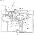
- FIG. 1 is a schematic view of a normal automatic analyzer to which the invention is applied.
- reaction containers 2 are arranged circumferentially on a reaction disk 1.
- a plurality of reagent bottles 10 can be arranged circumferentially in a reagent disk 9.
- a detergent bottle 10a can also be arranged in the reagent disk 9.
- a sample transferring mechanism 17 which moves a rack 16 mounted with sample containers 15 is installed in the vicinity of the reaction disk 1.
- Reagent dispensing mechanisms 7, 8 which are rotatable and vertically movable are installed between the reaction disk 1 and the reagent disk 9.
- the reagent dispensing mechanisms 7, 8 include reagent probes 7a, 8a, respectively.
- the reagent probe 7a or 8a is moved vertically and horizontally by the reagent dispensing mechanism 7 or 8.
- a reagent syringe 18 is connected to the reagent probe 7a or 8a.
- the reagent syringe 18 suctions and discharges a reagent by the reagent probe 7a or 8a.
- the reagent syringe 18 suctions and discharges washing water in the reagent probe 7a or 8a or washing water or detergent from the detergent bottle 10a to wash the inside of the reagent probe 7a.
- a sample dispensing mechanism 11 which is rotatable and vertically movable is installed between the reaction disk 1 and the sample transferring mechanism 17.
- the sample dispensing mechanism 11 includes a sample probe 11a.
- a sample syringe 19 is connected to the sample probe 11a.
- the sample probe 11a moves vertically and horizontally while drawing a circular arc around a rotation axis to dispense a sample into the reaction containers 2 from the sample containers 15.
- a washing mechanism 3 For analyzing the sample in the reaction containers 2, a washing mechanism 3, a spectrophotometer 4, mixing mechanisms 5, 6, the reagent disk 9, and the sample transferring mechanism 17 are arranged around the reaction disk 1.
- the spectrophotometer 4 receives light emitted from a light source (not shown).
- Washing tanks 30, 31, 32, 33, and 34 are arranged on the operation range of the mixing mechanisms 5, 6, the reagent dispensing mechanisms 7, 8, and the sample dispensing mechanism 11, respectively.
- the washing tanks 30, 31 are for the mixing mechanisms 5, 6, the washing tanks 32, 33 are for the reagent probes 7a, 8a, and the washing tank 30 is for the sample probe 11a.
- a vacuum suction device 50 for vacuum suction of analyzed reaction liquid remaining in the reaction containers 2 is connected to the washing mechanism 3.
- FIG. 2 is a view schematically showing the washing mechanism 3, the vacuum suction device 50, the reagent probe 7a, and the washing tank 32.
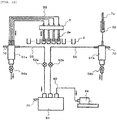
- Suction nozzles 3a provided in the washing mechanism 3 are connected to a waste liquid bin 51a (vacuum bin), an electromagnetic valve 52a, a vacuum tank 53, and a vacuum pump 54 through tubes 55.
- the washing tank 32 is connected to a waste liquid bin 51b (vacuum bin), an electromagnetic valve 52b, the vacuum tank 53, and the vacuum pump 54 through the tubes 55.
- the vacuum tank 53 is always in a vacuum state by suction performed by the vacuum pump 54.
- the electromagnetic valve 52a opens at the timing of suctioning the analyzed reaction liquid, so that the vacuum tank 53 utilizes vacuum pressure to suction the analyzed reaction liquid from the reaction containers 2.
- the electromagnetic valve 52b opens at the timing of suctioning the washing liquid adhering to the probe, so that the vacuum tank 53 utilizes the vacuum pressure to suction the adhered washing liquid from the reagent probe 7a.
- the waste liquid bin 51a or 51b is a container for storing the suctioned analyzed reaction liquid or the suctioned washing liquid. That is, the waste liquid bin 51a or 51b serves to prevent the analyzed reaction liquid or the washing liquid from entering the vacuum tank 53.
- a sample to be inspected such as blood is contained in the sample containers 15 placed on the rack 16 carried by the sample transferring mechanism 17. Further, each mechanism is connected to a controller 21 and operation of each mechanism is controlled by the controller 21.
- the sample to be inspected is dispensed from the sample containers 15 to the reaction containers 2 by the sample probe 11a.
- the reagent is dispensed from the reagent bottles 10 to the reaction containers 2 by the reagent probe 7a.
- the sample and the reagent are mixed by the mixing mechanisms 5, 6, and the mixed liquid is irradiated with light emitted from the light source, and the emitted light is received by the spectrophotometer 4.
- the controller 21 calculates the concentration of a predetermined component contained in the sample based on the amount of the received light.
- the sample is analyzed by such a method.
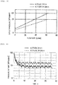
- FIG. 3 is a diagram showing characteristics of flow rate and pressure of a vacuum pump when the altitude changes. As shown in the diagram, the outlet pressure of the vacuum pump at an altitude of 3000 m is lower than the outlet pressure of the vacuum pump at an altitude of 0 m even when the vacuum pump exhausts gas at a certain flow rate.
- P* 1 is 101.32 kPa
- P* 2 is 21.33 kPa
- P 1 is 70.12 kPa (atmospheric pressure at an altitude of 3000 m)
- P 2 will be 14.8 kPa.
- P* 1 - P* 2 80.0 kPa when the head of the vacuum pump is at an altitude of 0 m
- P 1 - P 2 55.3 kPa when the head of the vacuum pump is at an altitude of 3000 m, and it is expected that the performance is reduced by about 30%.
- the suction amount of the analyzed reaction liquid that can be suctioned by the suction nozzle 3a provided in the washing mechanism 3 is determined by the pressure difference between the pressure in the vacuum tank 53 and the inlet pressure of the suction nozzles 3a, that is, the external atmospheric pressure. That is, the flow rate is determined such that the pressure difference from the vacuum tank 53 to the suction nozzle 3a and the pressure resistance associated with the suction flow rate are balanced.
- the performance of the vacuum pump 54 is lowered, and the pressure difference between the pressure of the vacuum tank 53 and the inlet pressure of the suction nozzles 3a, that is, the external atmospheric pressure, is smaller than the pressure difference at the altitude of 0 m.
- the suction flow rate by the suction nozzles 3a is reduced, the analyzed reaction liquid cannot be sufficiently suctioned.
- Pressure, flow rate, and temperature in pipelines were evaluated using a pipeline network numerical simulation technique.
- the pressure, the flow rate, and the temperature in the pipes can be analyzed by modeling each of the pipes, the pumps, the vacuum tank 53, and the vacuum bins as an one-dimensional flow path.
- the pipeline resistance can be determined from a pipe friction loss factor, the diameter and the length of the pipeline, which can be determined according to a widely known Moody diagram.
- the vacuum pump 54 was analyzed by modeling using characteristics of the flow rate and pressure of the pump which are obtained from a catalog or the like. By assuming that the tank capacity is a setting variable and an isothermal change is made in the vacuum tank 53, the pressure is determined according to the flow rates that flows in and flows out of the vacuum tank 53.
- the electromagnetic valve 52a performs modeling to enable and disable the pipeline according to the opening and closing timings, and then analysis is performed.
- FIG. 4 shows the pressure history of the vacuum tank 53 obtained by the analysis. It can be known that, when the analyzer is installed in an environment with an altitude of 3000 m, the performance of the vacuum pump 54 is lowered and the degree of vacuum of the vacuum tank 53 is greatly reduced. Since the degree of vacuum in the vacuum tank 53 is reduced, the suction flow rate is reduced, and the stability of the device is impaired due to the decrease in the suction capacity.
- a control mechanism 60 for changing the performance of the vacuum pump 54 according to a change in an external environment such as altitude is mounted.
- the control mechanism 60 can change the rotation speed of the vacuum pump according to the change of the external atmospheric pressure, so that the performance of the vacuum pump can be changed according to the change of the external environment, and the decrease in the suction flow rate can be prevented.
- the control mechanism 60 controls the vacuum pump so as to increase the rotation speed of the vacuum pump because the suction flow rate decreases in an area with high altitude.
- the control mechanism 60 may control the vacuum pump 54 as the same controller as the controller 21, or may be a controller different from the controller 21.
- a pressure sensor 61 capable of measuring the pressure in the vacuum tank 53 is mounted.
- the pressure sensor 61 may measure, as a measured value, the difference between the pressure in the vacuum tank 53 and the external atmospheric pressure.
- the pressure of the vacuum tank 53 is adjusted by controlling the rotation speed of the vacuum pump so as to make the pressure value the same as the pressure value at an altitude of 0 m.
- a device having such a control mechanism 60 can have stable suction performance at all times.
- the control mechanism 60 can change the rotation speed of the vacuum pump 54 according to the pressure value (the pressure in the vacuum tank 53, the pressure difference between the pressure in the vacuum tank 53 and the external atmospheric pressure, or the like) measured by the pressure sensor 61 which is provided in the vacuum tank 53.
- the pressure sensor 61 it is sufficient to use the pressure sensor 61 in the vacuum tank 53 only at a setting time. After the adjustment, it is sufficient if the vacuum tank 53 is operated at a rotation speed at the setting time, and the vacuum pressure and the suction flow rate in the vacuum tank 53 are sufficient. Since it is sufficient to use the pressure sensor 61 only at the setting time, the pressure sensor may be removed after the setting time is passed. In any case, it will be fine if the control mechanism 60 can change the rotation speed of the vacuum pump 54 according to the pressure difference between the external atmospheric pressure and the pressure in the vacuum tank 53.
- control mechanism 60 capable of changing the rotation speed of the vacuum pump and changing the rotation speed in a higher accuracy using a pressure sensor as in the first embodiment
- an example may be considered in which the pressure value of the pressure sensor is used only at the setting time as in the second embodiment.
- the pressure difference become identical even in an environment with different altitudes and the performance of the vacuum pump 54 can be improved.
- the flow rate will always be substantially constant, analyzed reaction liquid can be reliably suctioned from a reaction container, and the analyzed reaction liquid is always collected in a waste bin and does not flow to the vacuum pump.
- the degree of vacuum in the vacuum tank 53 may be increased by simply connecting a plurality of vacuum pumps 54 in series, instead of performing rotation speed control and pressure control.
- FIG. 6 shows an embodiment in which two vacuum pumps 54 are connected in series. Connecting the two vacuum pumps 54a, 54b in series significantly improves the performance of the vacuum pumps 54, so that the pressure in the vacuum tank 53 can be sufficiently reduced.
- a plurality of identical vacuum pumps 54 may be connected to each other depending on the environment, or a plurality of vacuum pumps 54 having different performances may be connected. The pump may be selected such that the suction performance of the pump and the pressure difference between the pressure in the vacuum tank 53 and the external atmospheric pressure become appropriate values according to the atmospheric pressure at which the analyzer is installed.
- the automatic analyzer of the third embodiment is installed at a predetermined altitude or higher, it is conceivable to connect a plurality of vacuum pumps in series, but for the same type of automatic analyzer installed below the predetermined altitude, it may not be necessary to connect the plurality of vacuum pumps in series in order to ensure the performance of the analyzer. Therefore, in the automatic analyzer of the third embodiment, the number of vacuum pumps connected in series is larger than that of vacuum pumps in the automatic analyzer of the same type installed at least below the predetermined altitude.
- FIG. 7 shows the pressure history in the vacuum tank when two identical vacuum pumps 54a, 54b are connected in series. It can be known that the pressure in the vacuum tank 53 is too low because the capacity of the vacuum pump 54 is too high. In such a case, as shown in FIG. 8 , a pressure adjustment mechanism 62 may be newly installed between the vacuum tank 53 and the vacuum pump 54. The suction pressure of a suction nozzle can be adjusted by the pressure adjustment mechanism 62.
- a fixed throttle is mounted as the pressure adjustment mechanism 62.
- a new throttle may be placed in a tube already installed in order to connect the vacuum tank 53 to the vacuum pump 54.
- tubes thinner than the existing tube may be connected in series.
- FIG. 9 shows an example of the fixed throttle.
- a member having a small pipeline diameter is inserted into the existing tube.
- the pipeline resistance cannot be sufficiently ensured.
- a thin tube may be connected between the existing tubes.
- a fixed throttle is provided in the tube, and the tube length and the tube diameter are changed, so that a desired pressure resistance can be obtained, and the pressure of the vacuum tank 53 can be easily adjusted.
- the fixed throttle shown in the present embodiment adjusts the pressure by narrowing the diameter of the pipeline. If the area where the analyzer is installed can be recognized in advance, since the altitude can be known, the diameter and the length of the throttle may be determined in advance, and then the throttle is mounted on the analyzer. Alternatively, the diameter and length of the throttle to be mounted may be determined by measuring the atmospheric pressure and the pressure in the vacuum tank when the analyzer is installed.
- the tube Since a tube having the same diameter is used in a normal automatic analyzer, when the pressure adjustment mechanism 62 is provided, the tube has a first section and a second section which have different cross-sectional areas. By providing the fixed throttle, the cross section of the second section is smaller than that of the first section.
- vacuum pump 54 Although only one vacuum pump 54 is shown in FIG. 8 , a plurality of vacuum pumps 54 connected in series may be included, or only one vacuum pump 54 which is a high-performance vacuum pump and can produce a higher degree of vacuum may be included.
- the pressure adjustment mechanism 62 may be a variable throttle. That is, as long as the variable throttle is an adjustable valve, the diameter of the throttle can be adjusted in any area with different altitudes, and the diameter of the throttle can be adjusted without taking much time.
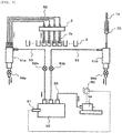
- the present embodiment is characterized in that an electromagnetic valve 57 is provided as the newly added pressure adjustment mechanism 62 in a flow path connecting the vacuum tank 53 to the vacuum pump 54.
- FIG. 10 is a diagram for explaining the configuration of the present embodiment. That is, the pressure in the vacuum tank 53 can be adjusted by adjusting opening and closing time of the electromagnetic valve 57.
- FIG. 11 shows opening and closing operations of the electromagnetic valve 52a. Further, FIG. 11 also shows opening and closing operations of the electromagnetic valve 57 newly added in the present embodiment.
- the opening and closing operations of the electromagnetic valve 57 are controlled by the controller 21. Since the suction nozzle 3a suctions reaction liquid when the electromagnetic valve 52a is open, the suction pressure of the suction nozzle can be adjusted by closing the electromagnetic valve 57 from an open state at this time. More preferably, not only is the operation of closing the electromagnetic valve 52a while the electromagnetic valve 52a is open performed once, but, as shown in the drawing, it is possible to perform the adjustment with higher accuracy by performing the opening and closing operations in small intervals.
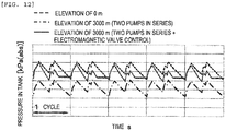
- FIG. 12 shows an analysis result when the pressure of the vacuum tank 53 is in a quasi-stationary state and is in a stable state.
- the horizontal axis represents time, and the vertical axis represents the pressure in the tank.
- a broken line indicates a pressure history in the vacuum tank 53 when one vacuum pump 54 is used at an altitude of 0 m.
- a dashed-dotted line indicates a pressure history when two vacuum pumps 54 are connected in series at an altitude of 3000 m.
- a solid line indicates a pressure history when two vacuum pumps 54 are connected in series at an altitude of 3000 m, the electromagnetic valve 57 is newly added as a pressure adjustment mechanism and the control as shown in FIG. 11 is added.
- the average pressure of the vacuum tank 53 is substantially the same value as that of the vacuum tank 53 at the altitude of 0 m. From this, it is expected that the suction amount from the suction nozzle 3a does not change at the altitude of 0 m and the altitude of 3000 m. Also, there are two times in a cycle that a main maximum value of pressure is equivalent to that at the altitude of 0 m, but there is only one time for the pressure waveform controlled by the electromagnetic valve 57, and the pressure in the vacuum tank can be controlled.
- the pressure history in the vacuum tank can be largely changed, and even if the altitude changes and the performance of the vacuum pump 54 is largely changed, stable suction performance can also be easily achieved.
- vacuum pump 54 Although only one vacuum pump 54 is shown in FIG. 10 , a plurality of vacuum pumps 54 connected in series may be included, or only one vacuum pump 54 which is a high-performance vacuum pump and can produce a higher degree of vacuum may be included.
- the vacuum pump is capable of obtaining a higher degree of vacuum than an automatic analyzer of the same type installed below the predetermined altitude.
- the number of the vacuum pumps is larger than that of the vacuum pumps in the automatic analyzer of the same type installed below the predetermined altitude.
- a pressure adjustment mechanism is provided in the vacuum tank 53 or the vacuum bin 51.
- an open tube 70 may be provided in the vacuum tank 53 or the vacuum bin 51.
- FIG. 13 shows a configuration of the present embodiment.
- the vacuum tank 53 or the vacuum bin 51 is provided with a hole in communication with the outside and air can be guided from the outside, it is possible to set an appropriate pressure value without decreasing the pressure in the vacuum tank more than necessary.
- the suction pressure of a suction nozzle can be adjusted by this hole.
- the open tube 70 is connected to the hole, and the air from the outside flows into the vacuum tank 53 or the vacuum bin 51 through the open tube 70 and the hole in communication with the outside in this order.
- the hole or the open tube 70 may be provided in either one or both of the vacuum tank 53 and the vacuum bin.
- the suction pressure of the suction nozzle can also be adjusted. Since the diameter of the open tube 70 connected to the hole can be changed easier than changing the diameter of the hole, it is desirable to provide an open tube from the viewpoint of ease of adjustment.
- the inner diameter of the open tube 70 is larger than ⁇ 2.0, there may be a problem that the pressure in the vacuum tank cannot be sufficiently reduced due to the air constantly flowing into through the open tube 70 with respect to the suction pressure of the vacuum pump. Therefore, the inner diameter of the open tube 70 is preferably ⁇ 2.0 or less.
- the suction pressure of the suction nozzle may be adjusted by suppressing the inflow of air by closing the hole with a closed tube and changing the length of the open tube,
- the hole may be an open throttle capable of varying the diameter of the hole.
- any type of pressure adjustment mechanism may be used as long as the device is capable of adjusting the pressure. That is, regardless of what kind of performance is provided for the pump, it is sufficient if a pressure adjustment mechanism capable of adjusting the pressure difference between the pressure in the vacuum tank and the external atmospheric pressure to a prescribed value can be installed between the vacuum tank and the vacuum pump.
- a hole in communication with the outside may be provided in the vacuum tank or the vacuum bin to adjust the pressure difference between the pressure in the vacuum tank and the external atmospheric pressure to the prescribed value.
- first to seventh embodiments an example is shown in which vacuum suction is performed by a common vacuum tank in a unit having a plurality of suction nozzles for suctioning liquid from a plurality of reaction containers and the washing tank for suctioning the washing liquid adhering to the probes.
- the vacuum tank common to the washing tank it is not necessary to use the vacuum tank common to the washing tank.
- the number of vacuum tanks and the number of vacuum pumps can be reduced by using the vacuum tank common to the washing tank.
- a washing tank for applying washing liquid to the probes and performing washing may be configured separately from a washing tank for suctioning the washing liquid. In the present description, even a washing tank used for suctioning the washing liquid and not involving washing can be considered as a washing tank in claims.
- control mechanism 60 may manually set the rotation speed and control the vacuum pump to be in the set rotation speed. In either case, the control mechanism 60 can change the rotation speed.
- the control mechanism 60 can change the rotation speed.
- "can change the rotation speed” described in the present description does not mean a temporary change in the rotation speed but means the change of the rotation speed in the stable state.
- the vacuum pump of the same specification as described in the present description means a vacuum pump of the same model number from the viewpoint of cost reduction.
- the vacuum bin as described in the present description is a buffer container connected between the suction nozzle and the vacuum tank regardless of the material.
- the vacuum bin is a container having a volume smaller than the vacuum tank.
- reaction disk 1 reaction disk, 2 reaction container, 3 washing mechanism, 3a suction nozzle, 4 spectrophotometer, 5, 6 mixing mechanism, 7, 8 reagent dispensing mechanism, 7a, 8a reagent probe, 9 reagent disk, 10 reagent bottle, 10a detergent bottle, 11 sample dispensing mechanism, 11a sample probe, 15 sample container, 16 rack, 17 sample transferring mechanism, 18 reagent syringe, 19 sample syringe, 21 controller, 30, 31 washing tank for mixing mechanism, 32, 33 wash tank for reagent probe, 34 wash tank for sample probe, 50 vacuum suction device, 51 waste liquid bin (vacuum bin), 52 electromagnetic valve, 53 vacuum tank, 54 vacuum pump, 55 tube, 57 electromagnetic valve, 60 control mechanism, 61 pressure sensor, 62 pressure adjustment mechanism, 70 open tube
Landscapes
- Physics & Mathematics (AREA)
- Health & Medical Sciences (AREA)
- Life Sciences & Earth Sciences (AREA)
- Chemical & Material Sciences (AREA)
- Analytical Chemistry (AREA)
- Biochemistry (AREA)
- General Health & Medical Sciences (AREA)
- General Physics & Mathematics (AREA)
- Immunology (AREA)
- Pathology (AREA)
- Engineering & Computer Science (AREA)
- Quality & Reliability (AREA)
- Automatic Analysis And Handling Materials Therefor (AREA)
- Sampling And Sample Adjustment (AREA)
Abstract
Description
- The present invention relates to an automatic analyzer including a vacuum suction device for vacuum suction of reaction liquid after analysis from a reaction container.
-
Patent Literature 1 discloses a blood suction device by vacuum suction.Patent Literature 1 discloses that a blood infiltration preventing container includes a main body and a lid body, and is placed on a container placing portion protruding upward from an upper surface portion of a case. Two openings are formed in the lid body, and a lower end of a connecting pipe of a pressure adjustment member is inserted into the main body through one opening and a lower end of a connecting pipe is inserted into the main body through another opening. It is disclosed that the pressure adjustment member is provided with a pressure adjustment valve at an appropriate position in the connecting pipe and suction pressure can be adjusted by changing a flow rate of air suctioned from a connecting tube by rotating the pressure adjustment valve. -
Patent Literature 2 discloses a vacuum suction device for vacuum suction of a reaction liquid or vacuum suction of a washing liquid or the like adhering to a probe.Patent Literature 2 discloses "An automatic analyzer including a vacuum pump, a first vacuum tank connected to the vacuum pump, a reaction liquid suction unit connected to the first vacuum tank, a vacuum drying unit for vacuum drying a tip of a dispensing probe, and a second vacuum tank connected between the vacuum drying unit and the first vacuum tank." -
- PTL 1:
JP-A-H08-50086 - PTL 2:
JP-A-2005-308506 - The automatic analyzer may be installed in an area with greatly different environments so that the analyzer needs to be able to operate stably in various environments. That is, the analyzer should be stable even in a high-temperature and high-humidity environment such as a tropical area or a low-pressure environment at a highland. In particular, in recent years, due to the influence of globalization, if an automatic analyzer is installed in a high-altitude environment, there is a problem that stability decreases due to environmental change accompanying a change in external atmospheric pressure. In particular, it may be difficult to perform vacuum suction of an analyzed reaction liquid from a reaction container due to a decrease in suction performance of a vacuum pump.
-
Patent Literature 1 discloses the blood suction device by vacuum suction, in which blood suction can be performed at a suction speed corresponding to a difference in viscosity by installing the pressure adjustment member on an upstream side of the blood infiltration preventing container. However, the purpose of the blood infiltration preventing container disclosed inPatent Literature 1 is only for storing blood, and does not have a tank capacity enough to maintain sufficient vacuum pressure. Further, in the blood suction device disclosed inPatent Literature 1, the pressure adjustment member is installed on the upstream side of the blood infiltration preventing container, but in an automatic analyzer of the invention, since it is necessary to install a plurality of suction flow paths from one vacuum tank, it is difficult to install pressure adjustment members in a plurality of flow paths in terms of cost and complexity in assembly. In addition, this pressure adjustment member is used for performing adjustment according to the difference in the viscosity of blood at the time of blood suction, and the role thereof is basically different from the invention which is intended for a case where external environment such as atmospheric pressure is greatly different. -
Patent Literature 2 discloses the vacuum suction device for vacuum suction of the reaction liquid or vacuum suction of the washing liquid or the like adhering to the probe. However, as disclosed inPatent Literature 2, even if a plurality of vacuum tanks are provided, pressure in the tanks cannot be adjusted in response to a greatly different external environment such as atmospheric pressure. - An object of the invention is to provide an automatic analyzer that can be stably operated even in an area with different external environments such as altitude.
- One of representative automatic analyzers of the invention is an automatic analyzer including: a vacuum pump; a vacuum tank connected to the vacuum pump; a vacuum bin connected to the vacuum tank; a unit that includes a plurality of suction nozzles configured to suction liquid from a plurality of reaction containers and that is connected to the vacuum bin; and a pressure adjustment mechanism provided between the vacuum pump and the vacuum tank and configured to adjust suction pressure of the suction nozzles. The pressure adjustment mechanism is provided between the vacuum pump and the vacuum tank, which makes it possible to adjust a pressure difference between external atmospheric pressure and tank pressure according to the installation environment.
- Further, one of the other representative automatic analyzers of the invention is an automatic analyzer including: a vacuum pump; a vacuum tank connected to the vacuum pump, a vacuum bin connected to the vacuum tank; a unit that includes a plurality of suction nozzles configured to suction liquid from a plurality of reaction containers and that is connected to the vacuum bin, and a hole that is provided in the vacuum tank or the vacuum bin and that is in communication with outside . By providing the hole in communication with the outside in a vacuum tank or a vacuum bin, it possible to control the pressure difference between the pressure in the vacuum tank and the external atmospheric pressure where the analyzer is installed to be constant regardless of the installation environment.
- According to the invention, it is possible to provide an automatic analyzer that can be stably operated without being influenced by suction performance if the automatic analyzer is simply set even if being installed in an environment with different external atmospheric pressures.
- Problems, configurations, and effects other than the above will become apparent from the description of embodiments below.
-
- [
FIG. 1] FIG. 1 is a schematic view of an automatic analyzer to which the invention is applied. - [
FIG. 2] FIG. 2 is a schematic view of a washing device and a vacuum suction device shown inFIG. 1 . - [
FIG. 3] FIG. 3 is a diagram showing characteristics of flow rate and outlet pressure of a vacuum pump when altitude changes. - [
FIG. 4] FIG. 4 is a diagram showing pressure history in a vacuum tank when the altitude changes. - [
FIG. 5] FIG. 5 is a schematic view of the washing device and the vacuum suction device according to a first embodiment. - [
FIG. 6] FIG. 6 is a schematic view of a washing device and a vacuum suction device according to a third embodiment. - [
FIG. 7] FIG. 7 is a diagram showing pressure history in a vacuum tank in a case where two vacuum pumps are installed in series when altitude changes. - [
FIG. 8] FIG. 8 is a schematic view of a washing device and a vacuum suction device according to a fourth embodiment. - [
FIG. 9] FIG. 9 is a schematic view of a fixed throttle according to the fourth embodiment. - [
FIG. 10] FIG. 10 is a schematic view of a washing device and a vacuum suction device according to a sixth embodiment. - [
FIG. 11] FIG. 11 is a diagram showing an operation sequence of two electromagnetic valves according to the sixth embodiment. - [
FIG. 12] FIG. 12 is a view showing pressure history in a vacuum tank according to the sixth embodiment. - [
FIG. 13] FIG. 13 is a schematic view of a washing device and a vacuum suction device according to a seventh embodiment. - First to seventh embodiments will be described below with reference to
FIGS. 1 to 13 . - An embodiment of the invention will be described below with reference to the drawings.
-
FIG. 1 is a schematic view of a normal automatic analyzer to which the invention is applied. - In
FIG. 1 ,reaction containers 2 are arranged circumferentially on areaction disk 1. A plurality ofreagent bottles 10 can be arranged circumferentially in areagent disk 9. Adetergent bottle 10a can also be arranged in thereagent disk 9. Asample transferring mechanism 17 which moves arack 16 mounted withsample containers 15 is installed in the vicinity of thereaction disk 1. -
Reagent dispensing mechanisms reaction disk 1 and thereagent disk 9. Thereagent dispensing mechanisms reagent probes reagent probe reagent dispensing mechanism reagent syringe 18 is connected to thereagent probe reagent syringe 18 suctions and discharges a reagent by thereagent probe reagent syringe 18 suctions and discharges washing water in thereagent probe detergent bottle 10a to wash the inside of thereagent probe 7a. - A
sample dispensing mechanism 11 which is rotatable and vertically movable is installed between thereaction disk 1 and thesample transferring mechanism 17. Thesample dispensing mechanism 11 includes asample probe 11a. A sample syringe 19 is connected to thesample probe 11a. Thesample probe 11a moves vertically and horizontally while drawing a circular arc around a rotation axis to dispense a sample into thereaction containers 2 from thesample containers 15. - For analyzing the sample in the
reaction containers 2, awashing mechanism 3, aspectrophotometer 4, mixingmechanisms 5, 6, thereagent disk 9, and thesample transferring mechanism 17 are arranged around thereaction disk 1. Thespectrophotometer 4 receives light emitted from a light source (not shown). -
Washing tanks mechanisms 5, 6, thereagent dispensing mechanisms sample dispensing mechanism 11, respectively. Thewashing tanks mechanisms 5, 6, thewashing tanks washing tank 30 is for thesample probe 11a. - A
vacuum suction device 50 for vacuum suction of analyzed reaction liquid remaining in thereaction containers 2 is connected to thewashing mechanism 3. -
FIG. 2 is a view schematically showing thewashing mechanism 3, thevacuum suction device 50, thereagent probe 7a, and thewashing tank 32.Suction nozzles 3a provided in thewashing mechanism 3 are connected to awaste liquid bin 51a (vacuum bin), anelectromagnetic valve 52a, avacuum tank 53, and avacuum pump 54 throughtubes 55. Thewashing tank 32 is connected to awaste liquid bin 51b (vacuum bin), anelectromagnetic valve 52b, thevacuum tank 53, and thevacuum pump 54 through thetubes 55. Thevacuum tank 53 is always in a vacuum state by suction performed by thevacuum pump 54. Theelectromagnetic valve 52a opens at the timing of suctioning the analyzed reaction liquid, so that thevacuum tank 53 utilizes vacuum pressure to suction the analyzed reaction liquid from thereaction containers 2. Similarly, theelectromagnetic valve 52b opens at the timing of suctioning the washing liquid adhering to the probe, so that thevacuum tank 53 utilizes the vacuum pressure to suction the adhered washing liquid from thereagent probe 7a. Meanwhile, thewaste liquid bin waste liquid bin vacuum tank 53. - A sample to be inspected such as blood is contained in the
sample containers 15 placed on therack 16 carried by thesample transferring mechanism 17. Further, each mechanism is connected to acontroller 21 and operation of each mechanism is controlled by thecontroller 21. - The sample to be inspected is dispensed from the
sample containers 15 to thereaction containers 2 by thesample probe 11a. The reagent is dispensed from thereagent bottles 10 to thereaction containers 2 by thereagent probe 7a. In thereaction containers 2, the sample and the reagent are mixed by the mixingmechanisms 5, 6, and the mixed liquid is irradiated with light emitted from the light source, and the emitted light is received by thespectrophotometer 4. Thecontroller 21 calculates the concentration of a predetermined component contained in the sample based on the amount of the received light. The sample is analyzed by such a method. - Hereinafter, the reason why the vacuum suction amount of the analyzed reaction liquid is reduced or the vacuum suction amount of the washing liquid or the like adhering to the probe is reduced when the analyzer is installed in an area with a high altitude will be described.
- It is known that, in consideration of the theory of rotary machines, the performance of the rotary machines using gas as operation fluid, such as fans, compressors, vacuum pumps is reduced when being operated in the area with high altitude.
-
FIG. 3 is a diagram showing characteristics of flow rate and pressure of a vacuum pump when the altitude changes. As shown in the diagram, the outlet pressure of the vacuum pump at an altitude of 3000 m is lower than the outlet pressure of the vacuum pump at an altitude of 0 m even when the vacuum pump exhausts gas at a certain flow rate. - The reason why the performance of the vacuum pump is reduced when the altitude is high, that is, when the air pressure is lowered, can be described by using a performance conversion formula for a compression rotary machine. That is, if Reynolds numbers are not significantly different, the performance can be converted based on law of similarity. When a prescribed state is indicated by *, a pump inlet is indicated by 1, and a pump outlet is indicated by 2, a pressure ratio at prescribed conditions can be expressed as follows.

- For example, in the case of the vacuum pump shown in the diagram, if P*1 is 101.32 kPa, P*2 is 21.33 kPa, and P1 is 70.12 kPa (atmospheric pressure at an altitude of 3000 m), P2 will be 14.8 kPa. For this reason, P*1 - P*2 = 80.0 kPa when the head of the vacuum pump is at an altitude of 0 m, P1 - P2 = 55.3 kPa when the head of the vacuum pump is at an altitude of 3000 m, and it is expected that the performance is reduced by about 30%.
- The suction amount of the analyzed reaction liquid that can be suctioned by the
suction nozzle 3a provided in thewashing mechanism 3 is determined by the pressure difference between the pressure in thevacuum tank 53 and the inlet pressure of thesuction nozzles 3a, that is, the external atmospheric pressure. That is, the flow rate is determined such that the pressure difference from thevacuum tank 53 to thesuction nozzle 3a and the pressure resistance associated with the suction flow rate are balanced. - When the device is installed at a high altitude, the performance of the
vacuum pump 54 is lowered, and the pressure difference between the pressure of thevacuum tank 53 and the inlet pressure of thesuction nozzles 3a, that is, the external atmospheric pressure, is smaller than the pressure difference at the altitude of 0 m. As a result, since the suction flow rate by thesuction nozzles 3a is reduced, the analyzed reaction liquid cannot be sufficiently suctioned. - Therefore, numerical simulation was conducted to examine the influence of the performance reduction of the
vacuum pump 54 on the pressure of thevacuum tank 53 and the suction flow rate of thesuction nozzles 3a. - Pressure, flow rate, and temperature in pipelines were evaluated using a pipeline network numerical simulation technique. In this analysis program, the pressure, the flow rate, and the temperature in the pipes can be analyzed by modeling each of the pipes, the pumps, the
vacuum tank 53, and the vacuum bins as an one-dimensional flow path. The pipeline resistance can be determined from a pipe friction loss factor, the diameter and the length of the pipeline, which can be determined according to a widely known Moody diagram. Thevacuum pump 54 was analyzed by modeling using characteristics of the flow rate and pressure of the pump which are obtained from a catalog or the like. By assuming that the tank capacity is a setting variable and an isothermal change is made in thevacuum tank 53, the pressure is determined according to the flow rates that flows in and flows out of thevacuum tank 53. Theelectromagnetic valve 52a performs modeling to enable and disable the pipeline according to the opening and closing timings, and then analysis is performed. -
FIG. 4 shows the pressure history of thevacuum tank 53 obtained by the analysis. It can be known that, when the analyzer is installed in an environment with an altitude of 3000 m, the performance of thevacuum pump 54 is lowered and the degree of vacuum of thevacuum tank 53 is greatly reduced. Since the degree of vacuum in thevacuum tank 53 is reduced, the suction flow rate is reduced, and the stability of the device is impaired due to the decrease in the suction capacity. - Thus, as shown in
FIG. 5 , in the present embodiment, acontrol mechanism 60 for changing the performance of thevacuum pump 54 according to a change in an external environment such as altitude is mounted. As described above, thecontrol mechanism 60 can change the rotation speed of the vacuum pump according to the change of the external atmospheric pressure, so that the performance of the vacuum pump can be changed according to the change of the external environment, and the decrease in the suction flow rate can be prevented. For example, thecontrol mechanism 60 controls the vacuum pump so as to increase the rotation speed of the vacuum pump because the suction flow rate decreases in an area with high altitude. Thecontrol mechanism 60 may control thevacuum pump 54 as the same controller as thecontroller 21, or may be a controller different from thecontroller 21. - In addition, in the present embodiment, a
pressure sensor 61 capable of measuring the pressure in thevacuum tank 53 is mounted. Thepressure sensor 61 may measure, as a measured value, the difference between the pressure in thevacuum tank 53 and the external atmospheric pressure. The pressure of thevacuum tank 53 is adjusted by controlling the rotation speed of the vacuum pump so as to make the pressure value the same as the pressure value at an altitude of 0 m. A device having such acontrol mechanism 60 can have stable suction performance at all times. - In view of obtaining the stable suction performance at all times, it is desirable to mount the
pressure sensor 61. This is because thecontrol mechanism 60 can change the rotation speed of thevacuum pump 54 according to the pressure value (the pressure in thevacuum tank 53, the pressure difference between the pressure in thevacuum tank 53 and the external atmospheric pressure, or the like) measured by thepressure sensor 61 which is provided in thevacuum tank 53. - As another embodiment, it is sufficient to use the
pressure sensor 61 in thevacuum tank 53 only at a setting time. After the adjustment, it is sufficient if thevacuum tank 53 is operated at a rotation speed at the setting time, and the vacuum pressure and the suction flow rate in thevacuum tank 53 are sufficient. Since it is sufficient to use thepressure sensor 61 only at the setting time, the pressure sensor may be removed after the setting time is passed. In any case, it will be fine if thecontrol mechanism 60 can change the rotation speed of thevacuum pump 54 according to the pressure difference between the external atmospheric pressure and the pressure in thevacuum tank 53. - Besides providing the
control mechanism 60 capable of changing the rotation speed of the vacuum pump and changing the rotation speed in a higher accuracy using a pressure sensor as in the first embodiment, an example may be considered in which the pressure value of the pressure sensor is used only at the setting time as in the second embodiment. - Thus, by changing the rotation speed of the vacuum pump, the pressure difference become identical even in an environment with different altitudes and the performance of the
vacuum pump 54 can be improved. As a result, regardless of in which area an automatic analyzer equipped with this function is installed, the flow rate will always be substantially constant, analyzed reaction liquid can be reliably suctioned from a reaction container, and the analyzed reaction liquid is always collected in a waste bin and does not flow to the vacuum pump. - In addition, the degree of vacuum in the
vacuum tank 53 may be increased by simply connecting a plurality ofvacuum pumps 54 in series, instead of performing rotation speed control and pressure control.FIG. 6 shows an embodiment in which twovacuum pumps 54 are connected in series. Connecting the twovacuum pumps vacuum tank 53 can be sufficiently reduced. A plurality ofidentical vacuum pumps 54 may be connected to each other depending on the environment, or a plurality ofvacuum pumps 54 having different performances may be connected. The pump may be selected such that the suction performance of the pump and the pressure difference between the pressure in thevacuum tank 53 and the external atmospheric pressure become appropriate values according to the atmospheric pressure at which the analyzer is installed. - In a case where the automatic analyzer of the third embodiment is installed at a predetermined altitude or higher, it is conceivable to connect a plurality of vacuum pumps in series, but for the same type of automatic analyzer installed below the predetermined altitude, it may not be necessary to connect the plurality of vacuum pumps in series in order to ensure the performance of the analyzer. Therefore, in the automatic analyzer of the third embodiment, the number of vacuum pumps connected in series is larger than that of vacuum pumps in the automatic analyzer of the same type installed at least below the predetermined altitude.
- As a result, by substantially changing only the number of the vacuum pumps, approximately the same performance of the automatic analyzer can be ensured regardless of the altitude difference even automatic for the automatic analyzer of the same type. Further, from the viewpoint of cost reduction by mass production, it is desirable to connect the vacuum pumps of the same specification in series.
- In the third embodiment, when the vacuum pressure of the
vacuum tank 53 is adjusted, it is difficult to select a pump, and when the degree of vacuum of thevacuum tank 53 is high, the suction flow rate may become higher than necessary. In this case, analyzed reaction liquid cannot be sufficiently captured in thewaste liquid bin 51a (vacuum bin) and flows into the vacuum tank, and the analyzed reaction liquid may be stored in the vacuum tank.FIG. 7 shows the pressure history in the vacuum tank when twoidentical vacuum pumps vacuum tank 53 is too low because the capacity of thevacuum pump 54 is too high. In such a case, as shown inFIG. 8 , apressure adjustment mechanism 62 may be newly installed between thevacuum tank 53 and thevacuum pump 54. The suction pressure of a suction nozzle can be adjusted by thepressure adjustment mechanism 62. - In the present embodiment, a fixed throttle is mounted as the
pressure adjustment mechanism 62. A new throttle may be placed in a tube already installed in order to connect thevacuum tank 53 to thevacuum pump 54. Alternatively, tubes thinner than the existing tube may be connected in series. -
FIG. 9 shows an example of the fixed throttle. InFIG. 9(a) , a member having a small pipeline diameter is inserted into the existing tube. In the case of such a member, there is a possibility that the pipeline resistance cannot be sufficiently ensured. In this case, as shown inFIG. 9(b) , a thin tube may be connected between the existing tubes. In both cases, a fixed throttle is provided in the tube, and the tube length and the tube diameter are changed, so that a desired pressure resistance can be obtained, and the pressure of thevacuum tank 53 can be easily adjusted. - As the
pressure adjustment mechanism 62, the fixed throttle shown in the present embodiment adjusts the pressure by narrowing the diameter of the pipeline. If the area where the analyzer is installed can be recognized in advance, since the altitude can be known, the diameter and the length of the throttle may be determined in advance, and then the throttle is mounted on the analyzer. Alternatively, the diameter and length of the throttle to be mounted may be determined by measuring the atmospheric pressure and the pressure in the vacuum tank when the analyzer is installed. - Since a tube having the same diameter is used in a normal automatic analyzer, when the
pressure adjustment mechanism 62 is provided, the tube has a first section and a second section which have different cross-sectional areas. By providing the fixed throttle, the cross section of the second section is smaller than that of the first section. - Although only one
vacuum pump 54 is shown inFIG. 8 , a plurality ofvacuum pumps 54 connected in series may be included, or only onevacuum pump 54 which is a high-performance vacuum pump and can produce a higher degree of vacuum may be included. - Further, the
pressure adjustment mechanism 62 may be a variable throttle. That is, as long as the variable throttle is an adjustable valve, the diameter of the throttle can be adjusted in any area with different altitudes, and the diameter of the throttle can be adjusted without taking much time. - The present embodiment is characterized in that an
electromagnetic valve 57 is provided as the newly addedpressure adjustment mechanism 62 in a flow path connecting thevacuum tank 53 to thevacuum pump 54.FIG. 10 is a diagram for explaining the configuration of the present embodiment. That is, the pressure in thevacuum tank 53 can be adjusted by adjusting opening and closing time of theelectromagnetic valve 57. - In order to examine the control effect of the
electromagnetic valve 57, evaluation was performed using a pipeline network numerical simulation technique that can analyze the pressure, the flow rate, and the temperature in a pipeline. In order to simplify the description, an analysis was performed for a flow path for suctioning analyzed reaction liquid from thereaction containers 2. That is, the flow path is at the side of thewaste liquid bin 51a (vacuum bin) and theelectromagnetic valve 52a. Each pipeline was modeled as a one-dimensional pipeline, and then the analysis is performed. -
FIG. 11 shows opening and closing operations of theelectromagnetic valve 52a. Further,FIG. 11 also shows opening and closing operations of theelectromagnetic valve 57 newly added in the present embodiment. The opening and closing operations of theelectromagnetic valve 57 are controlled by thecontroller 21. Since thesuction nozzle 3a suctions reaction liquid when theelectromagnetic valve 52a is open, the suction pressure of the suction nozzle can be adjusted by closing theelectromagnetic valve 57 from an open state at this time. More preferably, not only is the operation of closing theelectromagnetic valve 52a while theelectromagnetic valve 52a is open performed once, but, as shown in the drawing, it is possible to perform the adjustment with higher accuracy by performing the opening and closing operations in small intervals. -
FIG. 12 shows an analysis result when the pressure of thevacuum tank 53 is in a quasi-stationary state and is in a stable state. The horizontal axis represents time, and the vertical axis represents the pressure in the tank. A broken line indicates a pressure history in thevacuum tank 53 when onevacuum pump 54 is used at an altitude of 0 m. Meanwhile, a dashed-dotted line indicates a pressure history when twovacuum pumps 54 are connected in series at an altitude of 3000 m. Further, a solid line indicates a pressure history when twovacuum pumps 54 are connected in series at an altitude of 3000 m, theelectromagnetic valve 57 is newly added as a pressure adjustment mechanism and the control as shown inFIG. 11 is added. - It can be known that by controlling the
electromagnetic valve 57, the average pressure of thevacuum tank 53 is substantially the same value as that of thevacuum tank 53 at the altitude of 0 m. From this, it is expected that the suction amount from thesuction nozzle 3a does not change at the altitude of 0 m and the altitude of 3000 m. Also, there are two times in a cycle that a main maximum value of pressure is equivalent to that at the altitude of 0 m, but there is only one time for the pressure waveform controlled by theelectromagnetic valve 57, and the pressure in the vacuum tank can be controlled. By controlling the opening and closing of theelectromagnetic valve 57 with respect to the electromagnetic valve 52 in this manner, the pressure history in the vacuum tank can be largely changed, and even if the altitude changes and the performance of thevacuum pump 54 is largely changed, stable suction performance can also be easily achieved. - Although only one
vacuum pump 54 is shown inFIG. 10 , a plurality ofvacuum pumps 54 connected in series may be included, or only onevacuum pump 54 which is a high-performance vacuum pump and can produce a higher degree of vacuum may be included. - Further, when the automatic analyzers according to the fourth to sixth embodiments are installed at a predetermined altitude or higher, it is desirable that the vacuum pump is capable of obtaining a higher degree of vacuum than an automatic analyzer of the same type installed below the predetermined altitude. When a plurality of vacuum pumps are connected in series, it is desirable that the number of the vacuum pumps is larger than that of the vacuum pumps in the automatic analyzer of the same type installed below the predetermined altitude. As a result, by substantially changing only the number of the vacuum pumps, approximately the same performance of the automatic analyzer can be ensured even if the automatic analyzer is installed in different altitudes. Further, from the viewpoint of cost reduction by mass production, it is desirable to connect the vacuum pumps of the same specification in series.
- In the present embodiment, a pressure adjustment mechanism is provided in the
vacuum tank 53 or the vacuum bin 51. In order to adjust the pressure difference between the pressure in the vacuum tank and the external atmospheric pressure, anopen tube 70 may be provided in thevacuum tank 53 or the vacuum bin 51.FIG. 13 shows a configuration of the present embodiment. - In the present embodiment, by installing a vacuum pump capable of achieving a sufficient vacuum pressure in the vacuum tank when the automatic analyzer is installed at an altitude of 3000 m and installing the
open tube 70 when the automatic analyzer is installed at an altitude of 0 m, an appropriate pressure value can be obtained without lowering the pressure in the vacuum tank more than necessary. - Since the
vacuum tank 53 or the vacuum bin 51 is provided with a hole in communication with the outside and air can be guided from the outside, it is possible to set an appropriate pressure value without decreasing the pressure in the vacuum tank more than necessary. The suction pressure of a suction nozzle can be adjusted by this hole. Theopen tube 70 is connected to the hole, and the air from the outside flows into thevacuum tank 53 or the vacuum bin 51 through theopen tube 70 and the hole in communication with the outside in this order. - The hole or the
open tube 70 may be provided in either one or both of thevacuum tank 53 and the vacuum bin. In addition, since the inflow amount of air from the outside can be adjusted by changing the diameter of the hole or theopen tube 70, the suction pressure of the suction nozzle can also be adjusted. Since the diameter of theopen tube 70 connected to the hole can be changed easier than changing the diameter of the hole, it is desirable to provide an open tube from the viewpoint of ease of adjustment. - That is, by substantially changing the presence or absence of the hole, the presence or absence of the
open tube 70, or the diameter of the open tube according to the altitude at which the automatic analyzer is installed, approximately the same performance of the automatic analyzer of the same type can be secured without changing the pump and flow path configuration even if the automatic analyzer is installed in different altitudes. Furthermore, from the viewpoint of cost reduction by mass production, it is desirable to use vacuum pumps and vacuum flow path networks of the same specification. If the inner diameter of theopen tube 70 is larger than ϕ 2.0, there may be a problem that the pressure in the vacuum tank cannot be sufficiently reduced due to the air constantly flowing into through theopen tube 70 with respect to the suction pressure of the vacuum pump. Therefore, the inner diameter of theopen tube 70 is preferably ϕ 2.0 or less. - From a viewpoint of common design of the vacuum tank and the vacuum bin, a hole is provided in advance, the suction pressure of the suction nozzle may be adjusted by suppressing the inflow of air by closing the hole with a closed tube and changing the length of the open tube,
- Further, the hole may be an open throttle capable of varying the diameter of the hole. By providing the
vacuum tank 53 or the vacuum bin 51 with the open throttle, it is possible to control the pressure difference between the pressure in thevacuum tank 53 and the external atmospheric pressure in which the analyzer is installed to be constant regardless of installation environment. - The first to seventh embodiments have been described above.
- Various modifications may be made without departing from the spirit of the invention. Basically, any type of pressure adjustment mechanism may be used as long as the device is capable of adjusting the pressure. That is, regardless of what kind of performance is provided for the pump, it is sufficient if a pressure adjustment mechanism capable of adjusting the pressure difference between the pressure in the vacuum tank and the external atmospheric pressure to a prescribed value can be installed between the vacuum tank and the vacuum pump. Alternatively, as the pressure adjustment mechanism, a hole in communication with the outside may be provided in the vacuum tank or the vacuum bin to adjust the pressure difference between the pressure in the vacuum tank and the external atmospheric pressure to the prescribed value.
- In first to seventh embodiments, an example is shown in which vacuum suction is performed by a common vacuum tank in a unit having a plurality of suction nozzles for suctioning liquid from a plurality of reaction containers and the washing tank for suctioning the washing liquid adhering to the probes. However, it is not necessary to use the vacuum tank common to the washing tank. However, the number of vacuum tanks and the number of vacuum pumps can be reduced by using the vacuum tank common to the washing tank. Although both referred to as a washing tank, a washing tank for applying washing liquid to the probes and performing washing may be configured separately from a washing tank for suctioning the washing liquid. In the present description, even a washing tank used for suctioning the washing liquid and not involving washing can be considered as a washing tank in claims.
- In the first and second embodiments, in addition to automatically determining the rotation speed, the
control mechanism 60 may manually set the rotation speed and control the vacuum pump to be in the set rotation speed. In either case, thecontrol mechanism 60 can change the rotation speed. However, since the rotation speed of the vacuum pump gradually increases until a stable state is reached, "can change the rotation speed" described in the present description does not mean a temporary change in the rotation speed but means the change of the rotation speed in the stable state. - In addition, the vacuum pump of the same specification as described in the present description means a vacuum pump of the same model number from the viewpoint of cost reduction.
- Further, the vacuum bin as described in the present description is a buffer container connected between the suction nozzle and the vacuum tank regardless of the material. For example, the vacuum bin is a container having a volume smaller than the vacuum tank.
- 1 reaction disk, 2 reaction container, 3 washing mechanism, 3a suction nozzle, 4 spectrophotometer, 5, 6 mixing mechanism, 7, 8 reagent dispensing mechanism, 7a, 8a reagent probe, 9 reagent disk, 10 reagent bottle, 10a detergent bottle, 11 sample dispensing mechanism, 11a sample probe, 15 sample container, 16 rack, 17 sample transferring mechanism, 18 reagent syringe, 19 sample syringe, 21 controller, 30, 31 washing tank for mixing mechanism, 32, 33 wash tank for reagent probe, 34 wash tank for sample probe, 50 vacuum suction device, 51 waste liquid bin (vacuum bin), 52 electromagnetic valve, 53 vacuum tank, 54 vacuum pump, 55 tube, 57 electromagnetic valve, 60 control mechanism, 61 pressure sensor, 62 pressure adjustment mechanism, 70 open tube
Claims (17)
- An automatic analyzer comprising:a vacuum pump;a vacuum tank connected to the vacuum pump;a vacuum bin connected to the vacuum tank;a unit that includes a plurality of suction nozzles configured to suction liquid from a plurality of reaction containers and that is connected to the vacuum bin; anda pressure adjustment mechanism provided between the vacuum pump and the vacuum tank and configured to adjust suction pressure of the suction nozzles.
- The automatic analyzer according to claim 1, wherein
the vacuum pump is connected to the vacuum tank by a tube, and
the pressure adjustment mechanism is a throttle provided in the tube. - The automatic analyzer according to claim 2, wherein
the tube has a first section and a second section having different cross-sectional areas, and
the second section has a smaller cross-sectional area than that of the first section by providing the throttle which is a fixed throttle. - The automatic analyzer according to claim 2, wherein
the throttle is a variable throttle of which throttle diameter can be changed. - The automatic analyzer according to claim 1 further comprising:a controller configured to control opening and closing of an electromagnetic valve, whereinthe pressure adjustment mechanism is the electromagnetic valve, andthe controller adjusts the suction pressure of the suction nozzles by closing the electromagnetic valve from opening when the suction nozzles suction liquid.
- The automatic analyzer according to any one of claims 1 to 5, wherein
the automatic analyzer is installed at a predetermined altitude or higher, and
the vacuum pump is capable of achieving a higher degree of vacuum compared to an automatic analyzer of the same type installed below the predetermined altitude. - The automatic analyzer according to claim 6, wherein
a plurality of vacuum pumps are connected in series and the number of vacuum pumps is larger than that of vacuum pumps of the automatic analyzer of the same type installed below the predetermined altitude. - The automatic analyzer according to claim 7, wherein
the plurality of vacuum pumps are vacuum pumps of the same specification. - An automatic analyzer comprising:a vacuum pump;a vacuum tank connected to the vacuum pump;a vacuum bin connected to the vacuum tank;a unit that includes a plurality of suction nozzles configured to suction liquid from a plurality of reaction containers and that is connected to the vacuum bin; anda controller capable of changing rotation speed of the vacuum pump, whereinthe controller is capable of changing the rotation speed according to a change in external atmospheric pressure.
- The automatic analyzer according to claim 9, wherein
a pressure sensor is provided in the vacuum tank, and
the controller can change the rotation speed according to an pressure difference between the external atmospheric pressure and the pressure in the vacuum tank. - The automatic analyzer according to claim 10, wherein
the controller changes the rotation speed based on a pressure value measured by the pressure sensor. - An automatic analyzer comprising:a vacuum pump;a vacuum tank connected to the vacuum pump;a vacuum bin connected to the vacuum tank; anda unit that includes a plurality of suction nozzles configured to suction liquid from a plurality of reaction containers and that is connected to the vacuum bin, whereina plurality of vacuum pumps are connected in series.
- The automatic analyzer of claim 12, wherein
the automatic analyzer is installed at a predetermined altitude or higher, and
the number of the plurality of vacuum pumps in series connected is larger than that of vacuum pumps of an automatic analyzer of the same type installed below the predetermined altitude. - The automatic analyzer according to any one of claims 1 to 13 further comprising:
a washing tank connected to the vacuum tank and configured to suction washing liquid adhering to a probe by vacuum pressure of the vacuum tank. - An automatic analyzer comprising:a vacuum pump;a vacuum tank connected to the vacuum pump;a vacuum bin connected to the vacuum tank;a unit that includes a plurality of suction nozzles configured to suction liquid from a plurality of reaction containers and that is connected to the vacuum bin; anda hole that is provided in the vacuum tank or the vacuum bin and that is in communication with outside.
- The automatic analyzer of claim 15, wherein
the hole is used for guiding air from the outside to adjust the suction pressure of the suction nozzles. - The automatic analyzer according to claim 15 or 16 further comprising:
an open tube connected to the hole.
Applications Claiming Priority (2)
| Application Number | Priority Date | Filing Date | Title |
|---|---|---|---|
| JP2017058389A JP6749857B2 (en) | 2017-03-24 | 2017-03-24 | Automatic analyzer |
| PCT/JP2018/006869 WO2018173636A1 (en) | 2017-03-24 | 2018-02-26 | Automated analyzer |
Publications (3)
| Publication Number | Publication Date |
|---|---|
| EP3605111A1 true EP3605111A1 (en) | 2020-02-05 |
| EP3605111A4 EP3605111A4 (en) | 2021-01-06 |
| EP3605111B1 EP3605111B1 (en) | 2023-10-11 |
Family
ID=63586501
Family Applications (1)
| Application Number | Title | Priority Date | Filing Date |
|---|---|---|---|
| EP18771804.4A Active EP3605111B1 (en) | 2017-03-24 | 2018-02-26 | Automated analyzer |
Country Status (5)
| Country | Link |
|---|---|
| US (1) | US11624752B2 (en) |
| EP (1) | EP3605111B1 (en) |
| JP (1) | JP6749857B2 (en) |
| CN (1) | CN110226091B (en) |
| WO (1) | WO2018173636A1 (en) |
Families Citing this family (9)
| Publication number | Priority date | Publication date | Assignee | Title |
|---|---|---|---|---|
| CN110662964B (en) * | 2017-12-30 | 2023-08-25 | 深圳迈瑞生物医疗电子股份有限公司 | Waste liquid treatment device, method and sample analyzer |
| WO2020090508A1 (en) | 2018-10-31 | 2020-05-07 | 株式会社日立ハイテク | Automatic analysis device |
| US12360132B2 (en) | 2019-02-18 | 2025-07-15 | Hitachi High-Tech Corporation | Automatic analyzer |
| WO2021020260A1 (en) | 2019-07-26 | 2021-02-04 | 株式会社日立ハイテク | Mass spectrometer and control method therefor |
| KR102257845B1 (en) * | 2020-02-17 | 2021-05-28 | 한국표준과학연구원 | Flow control device and method for aspirating minimum quantity sample and cleaning interior of flow-path |
| JP7471168B2 (en) * | 2020-07-17 | 2024-04-19 | 株式会社日立ハイテク | Automatic analyzer and method for acquiring gear pump status of automatic analyzer |
| JP7630354B2 (en) * | 2021-05-21 | 2025-02-17 | 株式会社日立ハイテク | Automated Analysis Equipment |
| CN116007869A (en) * | 2023-02-09 | 2023-04-25 | 山东省医疗器械和药品包装检验研究院 | Vacuum blood sample collection container suction volume test instrument |
| WO2026140329A1 (en) * | 2024-12-23 | 2026-07-02 | 株式会社日立ハイテク | Automatic analysis device |
Family Cites Families (21)
| Publication number | Priority date | Publication date | Assignee | Title |
|---|---|---|---|---|
| US4358928A (en) * | 1980-08-28 | 1982-11-16 | General Motors Corporation | Altitude compensation vacuum pump control |
| JPS59168336A (en) | 1983-03-15 | 1984-09-22 | Terumo Corp | Apparatus for automatic sample collection and distribution |
| JPS62178787A (en) * | 1986-01-31 | 1987-08-05 | Oki Univac Kk | Vacuum pump control device |
| JPS6312965A (en) * | 1986-07-04 | 1988-01-20 | Tosoh Corp | Trap device for discharging cleaning solution |
| JPS6486729A (en) * | 1987-09-29 | 1989-03-31 | Nec Corp | Bus monitor device for token passing system |
| FR2640697B1 (en) * | 1988-12-16 | 1993-01-08 | Cit Alcatel | PUMPING ASSEMBLY FOR PROVIDING HIGH VACUUMS |
| JPH0325873U (en) * | 1989-07-24 | 1991-03-18 | ||
| JP3007394B2 (en) * | 1990-08-20 | 2000-02-07 | 株式会社大日本精機 | Device for injecting test liquid into test container |
| JP2936772B2 (en) | 1991-03-30 | 1999-08-23 | 株式会社島津製作所 | Biochemical automatic analyzer |
| JPH06324053A (en) * | 1993-05-13 | 1994-11-25 | Hitachi Ltd | Chemical automatic analyzer |
| JP3847357B2 (en) * | 1994-06-28 | 2006-11-22 | 株式会社荏原製作所 | Vacuum exhaust system |
| JP3400555B2 (en) | 1994-08-08 | 2003-04-28 | 株式会社三菱化学ビーシーエル | Blood suction device |
| JPH0972919A (en) * | 1995-09-07 | 1997-03-18 | Hitachi Ltd | Automatic analyzer |
| US6158416A (en) * | 1998-11-16 | 2000-12-12 | General Electric Company | Reduced emissions elevated altitude speed control for diesel engines |
| JP3811652B2 (en) * | 2002-03-05 | 2006-08-23 | 株式会社日立ハイテクノロジーズ | Dispensing device and automatic analyzer using the same |
| JP2005308506A (en) | 2004-04-21 | 2005-11-04 | Hitachi High-Technologies Corp | Automatic analyzer |
| WO2007071613A1 (en) * | 2005-12-20 | 2007-06-28 | Tecan Trading Ag | Conditioning device for liquid handling system liquids |
| JP4949389B2 (en) | 2006-05-11 | 2012-06-06 | ベックマン コールター, インコーポレイテッド | Automatic analyzer |
| DE102006050943B4 (en) * | 2006-10-28 | 2020-04-16 | Pfeiffer Vacuum Gmbh | Vacuum pump and method for operating the same |
| DE102009010064A1 (en) | 2009-02-21 | 2010-08-26 | Inficon Gmbh | Sniffing leak detector |
| CN104903729B (en) | 2013-01-21 | 2018-05-22 | 株式会社日立高新技术 | Automatic analysing apparatus |
-
2017
- 2017-03-24 JP JP2017058389A patent/JP6749857B2/en active Active
-
2018
- 2018-02-26 EP EP18771804.4A patent/EP3605111B1/en active Active
- 2018-02-26 WO PCT/JP2018/006869 patent/WO2018173636A1/en not_active Ceased
- 2018-02-26 CN CN201880007861.9A patent/CN110226091B/en active Active
- 2018-02-26 US US16/488,647 patent/US11624752B2/en active Active
Also Published As
| Publication number | Publication date |
|---|---|
| EP3605111B1 (en) | 2023-10-11 |
| JP6749857B2 (en) | 2020-09-02 |
| JP2018159682A (en) | 2018-10-11 |
| EP3605111A4 (en) | 2021-01-06 |
| WO2018173636A1 (en) | 2018-09-27 |
| US11624752B2 (en) | 2023-04-11 |
| CN110226091A (en) | 2019-09-10 |
| CN110226091B (en) | 2024-03-01 |
| US20200386779A1 (en) | 2020-12-10 |
Similar Documents
| Publication | Publication Date | Title |
|---|---|---|
| US11624752B2 (en) | Automatic analyzer | |
| CN109633117B (en) | A kind of dynamic quality control system of monitoring water quality on line equipment | |
| EP3144678B1 (en) | Automated analysis device | |
| CN107024377B (en) | Online dilution monitoring device for total hydrocarbons in waste gas | |
| EP3731954A1 (en) | Automatic liquid transfer optimization pipetting apparatus and method | |
| US20140137632A1 (en) | Device for checking the calibration of catching instruments measuring rainfall intensity | |
| CN206847994U (en) | A kind of sampler suitable for analysis meter | |
| CN107271707A (en) | The sampling device of a kind of sampler and the use device, detecting system | |
| KR20100029070A (en) | Valve leakby diagnostics | |
| CN202092927U (en) | Automatic kinematic viscosity tester | |
| US20160273951A1 (en) | Method for controlling pipetting operations | |
| WO2017177476A1 (en) | Evaluation system for determining technological parameters for dissolving of oil-displacing polymer in pipe | |
| CN202421189U (en) | High dilution factor water sample analysis device | |
| CN107064281B (en) | Online dilution monitoring method for total hydrocarbons in waste gas | |
| CN204882162U (en) | Self -disposable formula oil well associated gas hydrogen sulfide sampling test device of row of exempting from | |
| US20260043186A1 (en) | Dispensing fluids based on a flow characteristic | |
| RU2470283C2 (en) | Device for sampling from discharge pipeline (versions) | |
| WO2022244565A1 (en) | Automatic analysis device | |
| CN104632189A (en) | Automatic thickened oil detection system and automatic oil extraction assistant injection amount adjusting system | |
| CN109403951B (en) | Oil well three-phase metering integrated device | |
| CN208420451U (en) | Chemical analysis tests dedicated auxiliary automatic liquid-suction device | |
| RU2689458C1 (en) | Method for oil compounding and system for its implementation | |
| JP4178122B2 (en) | Dispensing device and automatic analyzer equipped with the same | |
| CN107345957A (en) | A kind of liquid-way system of streaming immunoluminescence analyzer | |
| CN210450154U (en) | Pipeline cleaning system |
Legal Events
| Date | Code | Title | Description |
|---|---|---|---|
| STAA | Information on the status of an ep patent application or granted ep patent |
Free format text: STATUS: THE INTERNATIONAL PUBLICATION HAS BEEN MADE |
|
| PUAI | Public reference made under article 153(3) epc to a published international application that has entered the european phase |
Free format text: ORIGINAL CODE: 0009012 |
|
| STAA | Information on the status of an ep patent application or granted ep patent |
Free format text: STATUS: REQUEST FOR EXAMINATION WAS MADE |
|
| 17P | Request for examination filed |
Effective date: 20191024 |
|
| AK | Designated contracting states |
Kind code of ref document: A1 Designated state(s): AL AT BE BG CH CY CZ DE DK EE ES FI FR GB GR HR HU IE IS IT LI LT LU LV MC MK MT NL NO PL PT RO RS SE SI SK SM TR |
|
| AX | Request for extension of the european patent |
Extension state: BA ME |
|
| RAP1 | Party data changed (applicant data changed or rights of an application transferred) |
Owner name: HITACHI HIGH-TECH CORPORATION |
|
| DAV | Request for validation of the european patent (deleted) | ||
| DAX | Request for extension of the european patent (deleted) | ||
| A4 | Supplementary search report drawn up and despatched |
Effective date: 20201208 |
|
| RIC1 | Information provided on ipc code assigned before grant |
Ipc: G01N 35/10 20060101AFI20201202BHEP Ipc: G01N 35/00 20060101ALI20201202BHEP |
|
| STAA | Information on the status of an ep patent application or granted ep patent |
Free format text: STATUS: EXAMINATION IS IN PROGRESS |
|
| 17Q | First examination report despatched |
Effective date: 20220706 |
|
| GRAP | Despatch of communication of intention to grant a patent |
Free format text: ORIGINAL CODE: EPIDOSNIGR1 |
|
| STAA | Information on the status of an ep patent application or granted ep patent |
Free format text: STATUS: GRANT OF PATENT IS INTENDED |
|
| INTG | Intention to grant announced |
Effective date: 20230424 |
|
| GRAS | Grant fee paid |
Free format text: ORIGINAL CODE: EPIDOSNIGR3 |
|
| GRAA | (expected) grant |
Free format text: ORIGINAL CODE: 0009210 |
|
| STAA | Information on the status of an ep patent application or granted ep patent |
Free format text: STATUS: THE PATENT HAS BEEN GRANTED |
|
| RIN1 | Information on inventor provided before grant (corrected) |
Inventor name: KAWAHARA, TETSUJI Inventor name: MORI, TAKAMICHI Inventor name: INABA, TOORU |
|
| AK | Designated contracting states |
Kind code of ref document: B1 Designated state(s): AL AT BE BG CH CY CZ DE DK EE ES FI FR GB GR HR HU IE IS IT LI LT LU LV MC MK MT NL NO PL PT RO RS SE SI SK SM TR |
|
| REG | Reference to a national code |
Ref country code: GB Ref legal event code: FG4D |
|
| REG | Reference to a national code |
Ref country code: CH Ref legal event code: EP |
|
| REG | Reference to a national code |
Ref country code: DE Ref legal event code: R096 Ref document number: 602018059210 Country of ref document: DE |
|
| REG | Reference to a national code |
Ref country code: IE Ref legal event code: FG4D |
|
| REG | Reference to a national code |
Ref country code: LT Ref legal event code: MG9D |
|
| REG | Reference to a national code |
Ref country code: NL Ref legal event code: MP Effective date: 20231011 |
|
| REG | Reference to a national code |
Ref country code: AT Ref legal event code: MK05 Ref document number: 1620697 Country of ref document: AT Kind code of ref document: T Effective date: 20231011 |
|
| PG25 | Lapsed in a contracting state [announced via postgrant information from national office to epo] |
Ref country code: NL Free format text: LAPSE BECAUSE OF FAILURE TO SUBMIT A TRANSLATION OF THE DESCRIPTION OR TO PAY THE FEE WITHIN THE PRESCRIBED TIME-LIMIT Effective date: 20231011 |
|
| PG25 | Lapsed in a contracting state [announced via postgrant information from national office to epo] |
Ref country code: GR Free format text: LAPSE BECAUSE OF FAILURE TO SUBMIT A TRANSLATION OF THE DESCRIPTION OR TO PAY THE FEE WITHIN THE PRESCRIBED TIME-LIMIT Effective date: 20240112 |
|
| PG25 | Lapsed in a contracting state [announced via postgrant information from national office to epo] |
Ref country code: IS Free format text: LAPSE BECAUSE OF FAILURE TO SUBMIT A TRANSLATION OF THE DESCRIPTION OR TO PAY THE FEE WITHIN THE PRESCRIBED TIME-LIMIT Effective date: 20240211 |
|
| PG25 | Lapsed in a contracting state [announced via postgrant information from national office to epo] |
Ref country code: LT Free format text: LAPSE BECAUSE OF FAILURE TO SUBMIT A TRANSLATION OF THE DESCRIPTION OR TO PAY THE FEE WITHIN THE PRESCRIBED TIME-LIMIT Effective date: 20231011 |
|
| PG25 | Lapsed in a contracting state [announced via postgrant information from national office to epo] |
Ref country code: AT Free format text: LAPSE BECAUSE OF FAILURE TO SUBMIT A TRANSLATION OF THE DESCRIPTION OR TO PAY THE FEE WITHIN THE PRESCRIBED TIME-LIMIT Effective date: 20231011 |
|
| PG25 | Lapsed in a contracting state [announced via postgrant information from national office to epo] |
Ref country code: ES Free format text: LAPSE BECAUSE OF FAILURE TO SUBMIT A TRANSLATION OF THE DESCRIPTION OR TO PAY THE FEE WITHIN THE PRESCRIBED TIME-LIMIT Effective date: 20231011 |
|
| PG25 | Lapsed in a contracting state [announced via postgrant information from national office to epo] |
Ref country code: LT Free format text: LAPSE BECAUSE OF FAILURE TO SUBMIT A TRANSLATION OF THE DESCRIPTION OR TO PAY THE FEE WITHIN THE PRESCRIBED TIME-LIMIT Effective date: 20231011 Ref country code: IS Free format text: LAPSE BECAUSE OF FAILURE TO SUBMIT A TRANSLATION OF THE DESCRIPTION OR TO PAY THE FEE WITHIN THE PRESCRIBED TIME-LIMIT Effective date: 20240211 Ref country code: GR Free format text: LAPSE BECAUSE OF FAILURE TO SUBMIT A TRANSLATION OF THE DESCRIPTION OR TO PAY THE FEE WITHIN THE PRESCRIBED TIME-LIMIT Effective date: 20240112 Ref country code: ES Free format text: LAPSE BECAUSE OF FAILURE TO SUBMIT A TRANSLATION OF THE DESCRIPTION OR TO PAY THE FEE WITHIN THE PRESCRIBED TIME-LIMIT Effective date: 20231011 Ref country code: BG Free format text: LAPSE BECAUSE OF FAILURE TO SUBMIT A TRANSLATION OF THE DESCRIPTION OR TO PAY THE FEE WITHIN THE PRESCRIBED TIME-LIMIT Effective date: 20240111 Ref country code: AT Free format text: LAPSE BECAUSE OF FAILURE TO SUBMIT A TRANSLATION OF THE DESCRIPTION OR TO PAY THE FEE WITHIN THE PRESCRIBED TIME-LIMIT Effective date: 20231011 Ref country code: PT Free format text: LAPSE BECAUSE OF FAILURE TO SUBMIT A TRANSLATION OF THE DESCRIPTION OR TO PAY THE FEE WITHIN THE PRESCRIBED TIME-LIMIT Effective date: 20240212 |
|
| PG25 | Lapsed in a contracting state [announced via postgrant information from national office to epo] |
Ref country code: SE Free format text: LAPSE BECAUSE OF FAILURE TO SUBMIT A TRANSLATION OF THE DESCRIPTION OR TO PAY THE FEE WITHIN THE PRESCRIBED TIME-LIMIT Effective date: 20231011 Ref country code: RS Free format text: LAPSE BECAUSE OF FAILURE TO SUBMIT A TRANSLATION OF THE DESCRIPTION OR TO PAY THE FEE WITHIN THE PRESCRIBED TIME-LIMIT Effective date: 20231011 Ref country code: PL Free format text: LAPSE BECAUSE OF FAILURE TO SUBMIT A TRANSLATION OF THE DESCRIPTION OR TO PAY THE FEE WITHIN THE PRESCRIBED TIME-LIMIT Effective date: 20231011 Ref country code: NO Free format text: LAPSE BECAUSE OF FAILURE TO SUBMIT A TRANSLATION OF THE DESCRIPTION OR TO PAY THE FEE WITHIN THE PRESCRIBED TIME-LIMIT Effective date: 20240111 Ref country code: LV Free format text: LAPSE BECAUSE OF FAILURE TO SUBMIT A TRANSLATION OF THE DESCRIPTION OR TO PAY THE FEE WITHIN THE PRESCRIBED TIME-LIMIT Effective date: 20231011 Ref country code: HR Free format text: LAPSE BECAUSE OF FAILURE TO SUBMIT A TRANSLATION OF THE DESCRIPTION OR TO PAY THE FEE WITHIN THE PRESCRIBED TIME-LIMIT Effective date: 20231011 |
|
| PG25 | Lapsed in a contracting state [announced via postgrant information from national office to epo] |
Ref country code: DK Free format text: LAPSE BECAUSE OF FAILURE TO SUBMIT A TRANSLATION OF THE DESCRIPTION OR TO PAY THE FEE WITHIN THE PRESCRIBED TIME-LIMIT Effective date: 20231011 |
|
| REG | Reference to a national code |
Ref country code: DE Ref legal event code: R097 Ref document number: 602018059210 Country of ref document: DE |
|
| PG25 | Lapsed in a contracting state [announced via postgrant information from national office to epo] |
Ref country code: CZ Free format text: LAPSE BECAUSE OF FAILURE TO SUBMIT A TRANSLATION OF THE DESCRIPTION OR TO PAY THE FEE WITHIN THE PRESCRIBED TIME-LIMIT Effective date: 20231011 |
|
| PG25 | Lapsed in a contracting state [announced via postgrant information from national office to epo] |
Ref country code: SK Free format text: LAPSE BECAUSE OF FAILURE TO SUBMIT A TRANSLATION OF THE DESCRIPTION OR TO PAY THE FEE WITHIN THE PRESCRIBED TIME-LIMIT Effective date: 20231011 |
|
| PG25 | Lapsed in a contracting state [announced via postgrant information from national office to epo] |
Ref country code: SM Free format text: LAPSE BECAUSE OF FAILURE TO SUBMIT A TRANSLATION OF THE DESCRIPTION OR TO PAY THE FEE WITHIN THE PRESCRIBED TIME-LIMIT Effective date: 20231011 Ref country code: SK Free format text: LAPSE BECAUSE OF FAILURE TO SUBMIT A TRANSLATION OF THE DESCRIPTION OR TO PAY THE FEE WITHIN THE PRESCRIBED TIME-LIMIT Effective date: 20231011 Ref country code: RO Free format text: LAPSE BECAUSE OF FAILURE TO SUBMIT A TRANSLATION OF THE DESCRIPTION OR TO PAY THE FEE WITHIN THE PRESCRIBED TIME-LIMIT Effective date: 20231011 Ref country code: IT Free format text: LAPSE BECAUSE OF FAILURE TO SUBMIT A TRANSLATION OF THE DESCRIPTION OR TO PAY THE FEE WITHIN THE PRESCRIBED TIME-LIMIT Effective date: 20231011 Ref country code: EE Free format text: LAPSE BECAUSE OF FAILURE TO SUBMIT A TRANSLATION OF THE DESCRIPTION OR TO PAY THE FEE WITHIN THE PRESCRIBED TIME-LIMIT Effective date: 20231011 Ref country code: DK Free format text: LAPSE BECAUSE OF FAILURE TO SUBMIT A TRANSLATION OF THE DESCRIPTION OR TO PAY THE FEE WITHIN THE PRESCRIBED TIME-LIMIT Effective date: 20231011 Ref country code: CZ Free format text: LAPSE BECAUSE OF FAILURE TO SUBMIT A TRANSLATION OF THE DESCRIPTION OR TO PAY THE FEE WITHIN THE PRESCRIBED TIME-LIMIT Effective date: 20231011 |
|
| PLBE | No opposition filed within time limit |
Free format text: ORIGINAL CODE: 0009261 |
|
| STAA | Information on the status of an ep patent application or granted ep patent |
Free format text: STATUS: NO OPPOSITION FILED WITHIN TIME LIMIT |
|
| 26N | No opposition filed |
Effective date: 20240712 |
|
| PG25 | Lapsed in a contracting state [announced via postgrant information from national office to epo] |
Ref country code: MC Free format text: LAPSE BECAUSE OF FAILURE TO SUBMIT A TRANSLATION OF THE DESCRIPTION OR TO PAY THE FEE WITHIN THE PRESCRIBED TIME-LIMIT Effective date: 20231011 |
|
| REG | Reference to a national code |
Ref country code: CH Ref legal event code: PL |
|
| PG25 | Lapsed in a contracting state [announced via postgrant information from national office to epo] |
Ref country code: LU Free format text: LAPSE BECAUSE OF NON-PAYMENT OF DUE FEES Effective date: 20240226 |
|
| PG25 | Lapsed in a contracting state [announced via postgrant information from national office to epo] |
Ref country code: CH Free format text: LAPSE BECAUSE OF NON-PAYMENT OF DUE FEES Effective date: 20240229 |
|
| GBPC | Gb: european patent ceased through non-payment of renewal fee |
Effective date: 20240226 |
|
| PG25 | Lapsed in a contracting state [announced via postgrant information from national office to epo] |
Ref country code: SI Free format text: LAPSE BECAUSE OF FAILURE TO SUBMIT A TRANSLATION OF THE DESCRIPTION OR TO PAY THE FEE WITHIN THE PRESCRIBED TIME-LIMIT Effective date: 20231011 |
|
| PG25 | Lapsed in a contracting state [announced via postgrant information from national office to epo] |
Ref country code: SI Free format text: LAPSE BECAUSE OF FAILURE TO SUBMIT A TRANSLATION OF THE DESCRIPTION OR TO PAY THE FEE WITHIN THE PRESCRIBED TIME-LIMIT Effective date: 20231011 Ref country code: LU Free format text: LAPSE BECAUSE OF NON-PAYMENT OF DUE FEES Effective date: 20240226 Ref country code: CH Free format text: LAPSE BECAUSE OF NON-PAYMENT OF DUE FEES Effective date: 20240229 |
|
| REG | Reference to a national code |
Ref country code: BE Ref legal event code: MM Effective date: 20240229 |
|
| PG25 | Lapsed in a contracting state [announced via postgrant information from national office to epo] |
Ref country code: BE Free format text: LAPSE BECAUSE OF NON-PAYMENT OF DUE FEES Effective date: 20240229 |
|
| PG25 | Lapsed in a contracting state [announced via postgrant information from national office to epo] |
Ref country code: GB Free format text: LAPSE BECAUSE OF NON-PAYMENT OF DUE FEES Effective date: 20240226 |
|
| PG25 | Lapsed in a contracting state [announced via postgrant information from national office to epo] |
Ref country code: IE Free format text: LAPSE BECAUSE OF NON-PAYMENT OF DUE FEES Effective date: 20240226 |
|
| PG25 | Lapsed in a contracting state [announced via postgrant information from national office to epo] |
Ref country code: IE Free format text: LAPSE BECAUSE OF NON-PAYMENT OF DUE FEES Effective date: 20240226 Ref country code: GB Free format text: LAPSE BECAUSE OF NON-PAYMENT OF DUE FEES Effective date: 20240226 Ref country code: BE Free format text: LAPSE BECAUSE OF NON-PAYMENT OF DUE FEES Effective date: 20240229 |
|
| PG25 | Lapsed in a contracting state [announced via postgrant information from national office to epo] |
Ref country code: CY Free format text: LAPSE BECAUSE OF FAILURE TO SUBMIT A TRANSLATION OF THE DESCRIPTION OR TO PAY THE FEE WITHIN THE PRESCRIBED TIME-LIMIT; INVALID AB INITIO Effective date: 20180226 |
|
| PG25 | Lapsed in a contracting state [announced via postgrant information from national office to epo] |
Ref country code: HU Free format text: LAPSE BECAUSE OF FAILURE TO SUBMIT A TRANSLATION OF THE DESCRIPTION OR TO PAY THE FEE WITHIN THE PRESCRIBED TIME-LIMIT; INVALID AB INITIO Effective date: 20180226 |
|
| PG25 | Lapsed in a contracting state [announced via postgrant information from national office to epo] |
Ref country code: FI Free format text: LAPSE BECAUSE OF FAILURE TO SUBMIT A TRANSLATION OF THE DESCRIPTION OR TO PAY THE FEE WITHIN THE PRESCRIBED TIME-LIMIT Effective date: 20231011 |
|
| PG25 | Lapsed in a contracting state [announced via postgrant information from national office to epo] |
Ref country code: TR Free format text: LAPSE BECAUSE OF FAILURE TO SUBMIT A TRANSLATION OF THE DESCRIPTION OR TO PAY THE FEE WITHIN THE PRESCRIBED TIME-LIMIT Effective date: 20231011 |
|
| PGFP | Annual fee paid to national office [announced via postgrant information from national office to epo] |
Ref country code: DE Payment date: 20260121 Year of fee payment: 9 |
|
| PGFP | Annual fee paid to national office [announced via postgrant information from national office to epo] |
Ref country code: FR Payment date: 20260121 Year of fee payment: 9 |