EP3605083B1 - Defect detection device, defect detection method, and program - Google Patents
Defect detection device, defect detection method, and program Download PDFInfo
- Publication number
- EP3605083B1 EP3605083B1 EP18774964.3A EP18774964A EP3605083B1 EP 3605083 B1 EP3605083 B1 EP 3605083B1 EP 18774964 A EP18774964 A EP 18774964A EP 3605083 B1 EP3605083 B1 EP 3605083B1
- Authority
- EP
- European Patent Office
- Prior art keywords
- ultrasonic elements
- ultrasonic
- ratio
- reception
- defect
- Prior art date
- Legal status (The legal status is an assumption and is not a legal conclusion. Google has not performed a legal analysis and makes no representation as to the accuracy of the status listed.)
- Active
Links
- 230000007547 defect Effects 0.000 title claims description 167
- 238000001514 detection method Methods 0.000 title claims description 76
- 230000005540 biological transmission Effects 0.000 claims description 177
- 229910000831 Steel Inorganic materials 0.000 claims description 115
- 239000010959 steel Substances 0.000 claims description 115
- 239000000523 sample Substances 0.000 claims description 89
- 238000004590 computer program Methods 0.000 claims 1
- 238000012545 processing Methods 0.000 description 100
- 238000000034 method Methods 0.000 description 32
- 238000003860 storage Methods 0.000 description 30
- 238000006073 displacement reaction Methods 0.000 description 18
- 230000007423 decrease Effects 0.000 description 15
- 238000002592 echocardiography Methods 0.000 description 11
- 239000000284 extract Substances 0.000 description 8
- 238000005520 cutting process Methods 0.000 description 6
- 238000007689 inspection Methods 0.000 description 5
- 238000004519 manufacturing process Methods 0.000 description 4
- XLYOFNOQVPJJNP-UHFFFAOYSA-N water Substances O XLYOFNOQVPJJNP-UHFFFAOYSA-N 0.000 description 4
- 239000011324 bead Substances 0.000 description 3
- 230000000694 effects Effects 0.000 description 2
- 230000035515 penetration Effects 0.000 description 2
- 230000000704 physical effect Effects 0.000 description 2
- 230000035945 sensitivity Effects 0.000 description 2
- 235000010627 Phaseolus vulgaris Nutrition 0.000 description 1
- 244000046052 Phaseolus vulgaris Species 0.000 description 1
- 230000001902 propagating effect Effects 0.000 description 1
- 238000003466 welding Methods 0.000 description 1
Images


Classifications
-
- G—PHYSICS
- G01—MEASURING; TESTING
- G01N—INVESTIGATING OR ANALYSING MATERIALS BY DETERMINING THEIR CHEMICAL OR PHYSICAL PROPERTIES
- G01N29/00—Investigating or analysing materials by the use of ultrasonic, sonic or infrasonic waves; Visualisation of the interior of objects by transmitting ultrasonic or sonic waves through the object
- G01N29/22—Details, e.g. general constructional or apparatus details
- G01N29/26—Arrangements for orientation or scanning by relative movement of the head and the sensor
- G01N29/262—Arrangements for orientation or scanning by relative movement of the head and the sensor by electronic orientation or focusing, e.g. with phased arrays
-
- G—PHYSICS
- G01—MEASURING; TESTING
- G01N—INVESTIGATING OR ANALYSING MATERIALS BY DETERMINING THEIR CHEMICAL OR PHYSICAL PROPERTIES
- G01N29/00—Investigating or analysing materials by the use of ultrasonic, sonic or infrasonic waves; Visualisation of the interior of objects by transmitting ultrasonic or sonic waves through the object
- G01N29/04—Analysing solids
-
- G—PHYSICS
- G01—MEASURING; TESTING
- G01N—INVESTIGATING OR ANALYSING MATERIALS BY DETERMINING THEIR CHEMICAL OR PHYSICAL PROPERTIES
- G01N29/00—Investigating or analysing materials by the use of ultrasonic, sonic or infrasonic waves; Visualisation of the interior of objects by transmitting ultrasonic or sonic waves through the object
- G01N29/22—Details, e.g. general constructional or apparatus details
- G01N29/24—Probes
-
- G—PHYSICS
- G01—MEASURING; TESTING
- G01N—INVESTIGATING OR ANALYSING MATERIALS BY DETERMINING THEIR CHEMICAL OR PHYSICAL PROPERTIES
- G01N29/00—Investigating or analysing materials by the use of ultrasonic, sonic or infrasonic waves; Visualisation of the interior of objects by transmitting ultrasonic or sonic waves through the object
- G01N29/22—Details, e.g. general constructional or apparatus details
- G01N29/26—Arrangements for orientation or scanning by relative movement of the head and the sensor
-
- G—PHYSICS
- G01—MEASURING; TESTING
- G01N—INVESTIGATING OR ANALYSING MATERIALS BY DETERMINING THEIR CHEMICAL OR PHYSICAL PROPERTIES
- G01N29/00—Investigating or analysing materials by the use of ultrasonic, sonic or infrasonic waves; Visualisation of the interior of objects by transmitting ultrasonic or sonic waves through the object
- G01N29/22—Details, e.g. general constructional or apparatus details
- G01N29/28—Details, e.g. general constructional or apparatus details providing acoustic coupling, e.g. water
-
- G—PHYSICS
- G01—MEASURING; TESTING
- G01N—INVESTIGATING OR ANALYSING MATERIALS BY DETERMINING THEIR CHEMICAL OR PHYSICAL PROPERTIES
- G01N29/00—Investigating or analysing materials by the use of ultrasonic, sonic or infrasonic waves; Visualisation of the interior of objects by transmitting ultrasonic or sonic waves through the object
- G01N29/22—Details, e.g. general constructional or apparatus details
- G01N29/30—Arrangements for calibrating or comparing, e.g. with standard objects
-
- G—PHYSICS
- G01—MEASURING; TESTING
- G01N—INVESTIGATING OR ANALYSING MATERIALS BY DETERMINING THEIR CHEMICAL OR PHYSICAL PROPERTIES
- G01N29/00—Investigating or analysing materials by the use of ultrasonic, sonic or infrasonic waves; Visualisation of the interior of objects by transmitting ultrasonic or sonic waves through the object
- G01N29/44—Processing the detected response signal, e.g. electronic circuits specially adapted therefor
- G01N29/4409—Processing the detected response signal, e.g. electronic circuits specially adapted therefor by comparison
- G01N29/4427—Processing the detected response signal, e.g. electronic circuits specially adapted therefor by comparison with stored values, e.g. threshold values
-
- G—PHYSICS
- G01—MEASURING; TESTING
- G01N—INVESTIGATING OR ANALYSING MATERIALS BY DETERMINING THEIR CHEMICAL OR PHYSICAL PROPERTIES
- G01N2291/00—Indexing codes associated with group G01N29/00
- G01N2291/26—Scanned objects
- G01N2291/263—Surfaces
- G01N2291/2634—Surfaces cylindrical from outside
-
- G—PHYSICS
- G01—MEASURING; TESTING
- G01N—INVESTIGATING OR ANALYSING MATERIALS BY DETERMINING THEIR CHEMICAL OR PHYSICAL PROPERTIES
- G01N2291/00—Indexing codes associated with group G01N29/00
- G01N2291/26—Scanned objects
- G01N2291/267—Welds
Definitions
- the present invention relates to a defect detection device and a defect detection method that detect a defect present in a welded part formed along a pipe longitudinal of a welded-steel pipe, and a program for causing a computer to execute this defect detection method.
- Patent Literature 1 describes an art in which ultrasonic beams are transmitted toward a welded part through an outer surface of a welded steel pipe from a flaw detection ultrasonic element group consisting of some ultrasonic elements of a plurality of ultrasonic elements composing a phased array probe, the ultrasonic beams reflected by the welded steel pipe including the welded part are received via the flaw detection ultrasonic element group that has transmitted the ultrasonic beams, and based on the received ultrasonic beams, whether or not a defect is present in the welded part is determined.
- Patent Literature 2 describes a defect detection device comprising a phased array probe, a transmitter, a receptor, and a defect determination unit.
- Patent Literature 3 describes a calibration method of an ultrasonic flaw detection.
- Patent Literature 4 describes an ultrasonic flaw detection apparatus for detecting a minute flaw generated in a welded portion of a welded steel pipe.
- the position of the welded part is sometimes displaced in the circumferential direction of the welded steel pipe depending on the welded steel pipe.
- the reflected ultrasonic beams reflected by the welded steel pipe including the welded part are received by using the same ultrasonic element group as the ultrasonic element group that has transmitted the ultrasonic beams toward the welded part, so that it is difficult to properly receive the reflected ultrasonic beams from a defect present in the welded part in the case where the position of the welded part is displaced in the circumferential direction of the welded steel pipe from an expected position. That is, the art described in Patent Literature 1 has caused a problem that the accuracy of detecting the defect decreases in the case where the position of the welded part is displaced in the circumferential direction of the welded steel pipe from an expected position.
- the present invention has been made in consideration of such problems, and an object thereof is to provide, when performing a defect inspection of a welded part of a welded steel pipe using a phased array probe, a mechanism capable of suppressing a decrease in accuracy of detecting a defect in the case where the position of the welded part is displaced in the circumferential direction of the welded steel pipe from an expected position.
- a defect detection device of the present invention is a defect detection device that detects a defect present in a welded part formed along a pipe longitudinal of a welded steel pipe, the device including: a phased array probe that is installed outside an outer surface of the welded steel pipe and includes a plurality of ultrasonic elements arranged therein; a transmission means configured to set n pieces of the ultrasonic elements, being some of a plurality of the ultrasonic elements composing the phased array probe, as transmission ultrasonic elements and transmits ultrasonic beams toward the welded part through the outer surface of the welded steel pipe from the transmission ultrasonic elements; a reception means configured to receive reflected ultrasonic beans being the ultrasonic beams reflected by the welded steel pipe including the welded part via reception ultrasonic elements consisting of m pieces, being larger than n pieces, of the ultrasonic elements including n pieces of the ultrasonic elements composing the transmission ultrasonic elements out of a plurality of the ultrasonic elements composing
- the present invention includes a defect detection method by the above-described defect detection device and a program for causing a computer to execute this defect detection method.
- the present invention it is possible to, when performing a defect inspection of a welded part of a welded steel pipe using a phased array probe, suppress a decrease in accuracy of detecting a defect in the case where the position of the welded part is displaced in the circumferential direction of the welded steel pipe from an expected position.
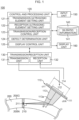
- Fig. 1 is a view illustrating one example of a schematic configuration of a defect detection device 100 according to the embodiment of the present invention.
- This defect detection device 100 is a device for detecting a defect 211 present in a welded part (weld surface) 210 formed along a pipe longitudinal of a welded steel pipe 200 such as an electric resistance welded steel pipe.
- Fig. 1 illustrates a cross section of the welded steel pipe 200 (the vicinity of a welded part 210 of the cross section of the welded steel pipe in more detail).
- the example where the defect 211 is present inside the welded part 210 is illustrated in Fig.
- the defect 211 is sometimes not present inside the welded part 210.
- the outside diameter of the welded steel pipe 200 is preferably 38.1 mm to 114.3 mm, for example, and the thickness (the length between an outer surface 200G and an inner surface 200N) of the welded steel pipe 200 is preferably 1.6 mm to 10 mm, for example.
- the defect detection device 100 is configured to include a phased array probe 110, a control and processing unit 120, a transmission/reception unit 130, a storage unit 140, an input unit 150, and a display unit 160 as illustrated in Fig. 1 .
- the phased array probe 110 is installed outside the outer surface 200G of the welded steel pipe 200 and is formed by having a plurality of ultrasonic elements 111 arranged therein.
- Fig. 1 illustrates an example where as a plurality of the ultrasonic elements 111 composing the phased array probe 110, N pieces of ultrasonic elements with ch 1 to ch N are formed.
- Fig. 1 illustrates, out of a plurality of the ultrasonic elements 111 composing the phased array probe 110, transmission ultrasonic elements 112 that transmit ultrasonic beams 113 toward the welded part 210 through the outer surface 200G of the welded steel pipe 200. On this occasion, the ultrasonic beams 113 illustrated in Fig.
- FIG. 1 illustrates, out of a plurality of the ultrasonic elements 111 composing the phased array probe 110, reception ultrasonic elements 114 that receive reflected ultrasonic beams being the ultrasonic beams 113 reflected by the welded steel pipe 200 including the welded part 210 (to be sometimes described as "reflected ultrasonic beams” simply below). Further, between the phased array probe 110 and the outer surface 200G of the welded steel pipe 200, for example, water exists as a medium for efficiently propagating the ultrasonic beams 113.
- the control and processing unit 120 controls configuration units of the defect detection device 100 and integrally controls operations of the defect detection device 100 based on input information input from the input unit 150, for example. Further, the control and processing unit 120 performs various pieces of processing based on input information input from the input unit 150, for example.
- the control and processing unit 120 is configured to include a transmission ultrasonic element setting unit 121, a reception ultrasonic element setting unit 122, a transmission/reception control unit 123, a defect determination unit 124, and a display control unit 125 as illustrated in Fig. 1 .
- the transmission ultrasonic element setting unit 121 sets n pieces of the ultrasonic elements, being some of a plurality of the ultrasonic elements 111 (N pieces in the example illustrated in Fig. 1 ) composing the phased array probe 110, as the transmission ultrasonic elements 112 based on input information input from the input unit 150, for example.
- the reception ultrasonic element setting unit 122 sets, out of a plurality of the ultrasonic elements 111 composing the phased array probe 110, m pieces, being larger than n pieces, of the ultrasonic elements including n pieces of the ultrasonic elements relating to the transmission ultrasonic elements 112 as the reception ultrasonic elements 114 based on input information input from the input unit 150, for example. On this occasion, the reception ultrasonic element setting unit 122 sets the reception ultrasonic elements 114 in consideration of SN ratio information 141 stored in the storage unit 140.
- the transmission/reception control unit 123 controls the transmission/reception unit 130 based on input information input from the input unit 150 and information set in the transmission ultrasonic element setting unit 121 and the reception ultrasonic element setting unit 122, for example. Concretely, the transmission/reception control unit 123 controls a transmission unit 131 in the transmission/reception unit 130 to cause the transmission ultrasonic elements 112 set by the transmission ultrasonic element setting unit 121 to transmit the ultrasonic beams 113. Further, the transmission/reception control unit 123 controls a reception unit 132 in the transmission/reception unit 130 to cause the reception ultrasonic elements 114 set by the reception ultrasonic element setting unit 122 to receive the reflected ultrasonic beams.
- the defect determination unit 124 determines whether or not the defect 211 is present in the welded part 210 based on the reflected ultrasonic beams received by the reception unit 132 in the transmission/reception unit 130.
- the display control unit 125 performs a control of displaying a determination result of the defect 211 by the defect determination unit 124 on the display unit 160. Further, the display control unit 125 performs a control of displaying various pieces of information on the display unit 160 as necessary.
- the transmission/reception unit 130 transmits and receives ultrasonic beams to and from the welded steel pipe 200 based on the control of the transmission/reception control unit 123.
- the transmission/reception unit 130 is configured to include the transmission unit 131 and the reception unit 132.
- the transmission unit 131 performs processing to transmit the ultrasonic beams 113 from the transmission ultrasonic elements 112 set by the transmission ultrasonic element setting unit 121 out of a plurality of the ultrasonic elements 111 composing the phased array probe 110.
- the transmission unit 131 performs processing to transmit the ultrasonic beams 113 from the transmission ultrasonic elements 112 to make the ultrasonic beams 113 that have entered the welded steel pipe through the outer surface 200G of the welded steel pipe 200 directly incident on the welded part 210 substantially vertically without reflecting on the inner surface 200N of the welded steel pipe 200 to focus on the welded part 210 based on the control of the transmission/reception control unit 123.
- the transmission unit 131 transmits the ultrasonic beam 113 from the transmission ultrasonic element 112 to refract the ultrasonic beam 113 at an angle ⁇ (about 70° in the example illustrated in Fig.
- the reception unit 132 performs processing to receive the reflected ultrasonic beams via the reception ultrasonic elements 114 set by the reception ultrasonic element setting unit 122 out of a plurality of the ultrasonic elements 111 composing the phased array probe 110.
- the storage unit 140 stores the SN ratio information 141 to be used when the reception ultrasonic element setting unit 122 sets the reception ultrasonic element 114.
- the SN ratio information 141 will be described later using Fig. 10 . Further, the storage unit 140 stores various pieces of information, programs, and so on to be used in the control and processing unit 120 and various pieces of information and so on obtained by processing of the control and processing unit 120.
- the input unit 150 inputs input information operation input by a user, for example, to the control and processing unit 120.
- the display unit 160 displays a determination result of the defect 211 by the defect determination unit 124 based on the control of the display control unit 125. Further, the display unit 160 displays various pieces of information based on the control of the display control unit 125.
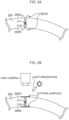
- Fig. 2A to Fig. 2C each are a view illustrating the embodiment of the present invention and illustrating one example of a method of determining the position of the welded part 210 illustrated in Fig. 1 .
- Fig. 2A is a schematic view illustrating one example of the case where for example, a band-shaped steel sheet (band steel) is welded at the welded part 210 to manufacture the welded steel pipe 200. As illustrated in Fig. 2A , at the time of welding, protuberant portions called beads are formed on the welded part 210.
- band steel band-shaped steel sheet
- Fig. 2B is a view illustrating a state where the beads illustrated in Fig. 2A are cut, light irradiation is performed on a cutting surface, and then a line camera photographs the cutting surface as one example for determining the position of the welded part 210.
- Fig. 2C is a view illustrating one example of a intensity profile of an image of the cutting surface photographed by the line camera illustrated in Fig. 2B .
- the intensity decreases due to the reason that the emitted light more irregularly reflects or the like, so that in the example illustrated in Fig. 2C , the position where the intensity most decreases is determined as the position of the welded part 210. That is, Fig.
- FIG. 2C illustrates an example where the center point of a cut width of the cutting surface is determined as the position of the welded part 210.
- the reason why the position of the welded part 210 is determined by the method illustrated in Fig. 2A to Fig. 2C is because it is difficult to directly measure the position of the welded part 210 after cutting the beads and determine the position in many cases.
- Fig. 3A and Fig. 3B each are a view illustrating a state of the case where the ultrasonic beams 113 are transmitted to the position of the welded part 210 determined by the method illustrated in Fig. 2C from the phased array probe 110 illustrated in Fig. 1 .
- Fig. 3A illustrates the case where the welded part 210 is actually located at the position (cut width center) of the welded part 210 determined by the method illustrated in Fig. 2C .
- the welded part 210 is actually located at the position of the welded part 210 determined by the method illustrated in Fig.
- Fig. 3B illustrates the case where the actual position of the welded part 210 is displaced in the circumferential direction of the welded steel pipe 200 from the position of the welded part 210 (cut width center) determined by the method illustrated in Fig. 2C .
- Fig. 3B illustrates the case where the actual position of the welded part 210 is displaced in the circumferential direction of the welded steel pipe 200 from the position of the welded part 210 (cut width center) determined by the method illustrated in Fig. 2C .
- Fig. 3B illustrates the case where the actual position of the welded part 210 is displaced in the circumferential direction of the welded steel pipe 200 from the position of the welded part 210 (cut width center) determined by the method illustrated in Fig. 2C .
- the actual position of the welded part 210 is displaced in the circumferential direction of the welded steel pipe 200 from the position of the welded part 210 determined by the method illustrated in Fig. 2C , so that it is impossible to set the focusing position 113b of the ultrasonic beams 113 at the actual position of the welded part 210 when performing a control so that the ultrasonic beams 113 focus on the position of the welded part 210 determined by the method illustrated in Fig. 2C . Therefore, in the case illustrated in Fig. 3B , a decrease in accuracy of detecting the defect 211 is concerned. Then, in order to suppress the decrease in accuracy of detecting the defect 211 in the case illustrated in Fig.
- this embodiment is designed to set m pieces, being larger than n pieces, of the ultrasonic elements including n pieces of the ultrasonic elements relating to the transmission ultrasonic elements 112 as the reception ultrasonic elements 114 by the reception ultrasonic element setting unit 122.
- Fig. 4 is a view illustrating the embodiment of the present invention and illustrating a setting example of a transmission delay pattern 410 of the transmission ultrasonic elements 112 relating to the transmission of the ultrasonic beams 113 by the transmission/reception control unit 123 in Fig. 1 and a setting example of a reception delay pattern 420 of the reception ultrasonic elements 114 relating to the reception of the reflected ultrasonic beams by the transmission/reception control unit 123 in Fig. 1 .
- the transmission delay pattern 410 and the reception delay pattern 420 that are illustrated in Fig. 4 are merely one example, and are not limited to the mode illustrated in Fig. 4 in this embodiment.
- the transmission/reception control unit 123 sets the transmission delay pattern 410 and the reception delay pattern 420 while considering the following factors, for example.
- the transmission/reception control unit 123 sets the transmission delay pattern 410 so as to refract the ultrasonic beam 113 at the angle ⁇ (about 70° in the example illustrated in Fig. 4 ) relative to the incident axis 113a on the outer surface 200G of the welded steel pipe 200 and make it directly incident on the welded part 210 substantially vertically without reflecting on the inner surface 200N of the welded steel pipe 200.
- the position of the phased array probe 110 is set in the following manner, for example.
- a line orthogonal to the welded part 210 is extended toward the outer surface 200G of the welded steel pipe 200. Then, the line is extended in the direction of the phased array probe 110 at the angle of refraction ⁇ based on Snell's law at the outer surface 200G of the welded steel pipe 200. Then, the phased array probe 110 is arranged so that the center of the phased array probe 110 can be located on the extension of the line and the extended line and an arrangement surface of the ultrasonic elements 111 can intersect at right angles.
- the distance (water distance) between the phased array probe 110 and the outer surface 200G of the welded steel pipe 200 is determined in consideration of an inspection time to be affected by a propagation time of the reflected ultrasonic beams from the defect 211 present in the welded part 210 (in which the propagation time, namely, the inspection time becomes long when the water distance is long), the fact that the effect of reverberation echoes going and returning between the phased array probe 110 and the outer surface 200G of the welded steel pipe 200 is ignorable, or the like.
- Fig. 5 is a view illustrating the embodiment of the present invention and illustrating a state of transmitting the ultrasonic beams 113 to a calibration pipe 300 for calibrating the welded steel pipe 200 in Fig. 1 from the phased array probe 110 in Fig. 1 .
- the calibration pipe 300 illustrated in Fig. 5 is a steel pipe for calibrating the welded steel pipe 200 illustrated in Fig. 1 and is a steel pipe with an artificial defect 311 formed in a second welded part 310 equivalent to the welded part 210 of the welded steel pipe 200. On this occasion, as the artificial defect 311, a through hole having a predetermined size is formed.
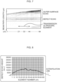
- Fig. 6 is a view illustrating a reference example and illustrating an SN ratio relating to reflected ultrasonic beams from the artificial defect 311 in the case where a number n of the transmission ultrasonic elements 112 illustrated in Fig. 5 is changed sequentially and the reception ultrasonic elements 114 are the same as the transmission ultrasonic elements 112.
- a first level value to a sixth level value are illustrated, which indicates that as the value of k of a kth level value increases, the SN ratio increases.
- the relationship of sound pressure sensitivity between the focusing-type phased array probe 110 and the focusing position 113b is thought that as the number of the ultrasonic elements 111 to be driven (a transmission/reception ch number) is larger, the sound pressure sensitivity increases as long as the distance between the phased array probe 110 and the focusing position 113b is fixed. That is, it is expected that as the number of the ultrasonic elements 111 to be driven (the transmission/reception ch number) is larger, the SN ratio increases.
- the number of the ultrasonic elements 111 to be driven the transmission/reception ch number
- the SN ratio increases to be maximum in a certain range, but as the number of the ultrasonic elements 111 to be driven (the transmission/reception ch number) increases thereafter, the SN ratio decreases. This is thought because with the increase in the number of the ultrasonic elements 111 to be driven (the transmission/reception ch number), the ultrasonic elements 111 to be driven are increased in the direction going away from the center of the phased array probe 110, and thereby the ultrasonic elements 111 increasing in excess of a certain range do not contribute to an improvement in the SN ratio but cause an increase in noise.
- the angle at which the ultrasonic beam to be transmitted enters an outer surface 300G in Fig. 5 varies according to the position of the ultrasonic element 111 to be driven, and thereby reciprocating sound pressure penetration changes, which is also one cause (the penetration decreases in the ultrasonic element 111 on an outer side where the incident angle increases (concretely in the direction toward ch N), for example).
- Fig. 7 is a view illustrating the embodiment of the present invention and illustrating a B scanned image relating to the reflected ultrasonic beams received by the ultrasonic elements 111 of the phased array probe 110 in which the number n of the transmission ultrasonic elements 112 illustrated in Fig. 5 is set to a predetermined number.
- the phased array probe 110 one composed of 64 pieces of the ultrasonic elements 111 in total is used.
- the transmission ultrasonic elements 112 24 pieces of the ultrasonic elements 111 (with element numbers of 21 ch to 44 ch concretely) are set.
- Fig. 7 as the phased array probe 110, one composed of 64 pieces of the ultrasonic elements 111 in total is used.
- 24 pieces of the ultrasonic elements 111 are set.
- Fig. 7 as the transmission ultrasonic elements 112
- Fig. 7 illustrates the B scanned image based on a waveform of the reflected ultrasonic beams received by the ultrasonic elements 111 (with element numbers of 1 ch to 64 ch) of the phased array probe 110 under the above-described conditions.
- a colored portion in a region described as an outer surface echo indicates that the ultrasonic elements 111 of the phased array probe 110 each have received the reflected ultrasonic beam from the outer surface 300G of the calibration pipe 300. Further, in Fig. 7 , a colored portion in a region described as a defect echo indicates that the ultrasonic elements 111 of the phased array probe 110 each have received the reflected ultrasonic beam from the artificial defect 311 with ⁇ 0.5 mm.
- Fig. 8 is a view illustrating the embodiment of the present invention and in which the maximum signal intensity of defect echos received by the ultrasonic elements 111 (with the element numbers of 1 ch to 64 ch) of the phased array probe 110 is illustrated as a defect echo height in the case of Fig. 7 .
- the horizontal axis indicates the ultrasonic elements 111 (with the element numbers of 1 ch to 64 ch) of the phased array probe 110 and the vertical axis indicates the defect echo height.
- Fig. 8 reveals that a defect echo with a large signal intensity is observed at the ultrasonic transducers 111 (the element numbers of 21 ch to 44 ch) set as the transmission ultrasonic elements 112, while at the other ultrasonic elements 111 (ch 1 to ch 20 and ch 45 to ch 64) as well, a defect echo with a certain or more signal intensity is observed.
- the ultrasonic elements 111 set as the transmission ultrasonic elements 112 are contained as the reception ultrasonic elements 114, thereby being able to contribute to an improvement in the SN ratio relating to the reflected ultrasonic beams from the artificial defect 311 (the defect echoes).
- Fig. 9A to Fig. 9D are views illustrating the embodiment of the present invention and illustrating one example of acquisition processing of the SN ratio information 141 stored in the storage unit 140 in Fig. 1 .
- Fig. 9A is a view illustrating a state of transmitting the ultrasonic beams 113 to the calibration pipe 300 for calibrating the welded steel pipe 200 in Fig. 1 from the phased array probe 110 in Fig. 1 .
- the same reference numerals and symbols are added to the same components as those illustrated in Fig. 5 . Further, Fig.
- FIGA also illustrates the case where the position of the second welded part 310 is displaced in the circumferential direction of the calibration pipe 300, in which relative to the phased array probe 110, a reference position of the second welded part 310 is set as a first position 901, a position where the position of the second welded part 310 is displaced clockwise from the first position 901 in the circumferential direction of the calibration pipe 300 by an angle ⁇ (an angle +o; when the clockwise rotation is set as the + direction) is set as a second position 902, and a position where the position of the second welded part 310 is displaced counterclockwise from the first position 901 in the circumferential direction of the calibration pipe 300 by an angle ⁇ (an angle - ⁇ when the clockwise rotation is set as the + direction) is set as a third position 903. Further, the focusing position 113b of the ultrasonic beams 113 is set to be located at the second welded part 310 when the second welded part 310 is located at the first position 901.
- Fig. 9B is a view in which the maximum signal intensity of defect echos received by the ultrasonic elements 111 (with the element numbers of 1 ch to 64 ch) of the phased array probe 110 is indicated as a defect echo height when the second welded part 310 exists at the first position 901 illustrated in Fig. 9A (namely, when a displacement angle from the reference position of the second welded part 310 relative to the phased array probe 110 is 0° ).
- the transmission ultrasonic elements 112 24 pieces of the ultrasonic elements 111 with the element numbers of 21 ch to 44 ch are used.
- Fig. 9C is a view in which the maximum signal intensity of defect echos received by the ultrasonic elements 111 (with the element numbers of 1 ch to 64 ch) of the phased array probe 110 is indicated as a defect echo height when the second welded part 310 exists at the second position 902 illustrated in Fig. 9A (namely, when the displacement angle from the reference position of the second welded part 310 relative to the phased array probe 110 is + ⁇ ).
- Fig. 9D is a view in which the maximum signal intensity of defect echos received by the ultrasonic elements 111 (with the element numbers of 1 ch to 64 ch) of the phased array probe 110 is indicated as a defect echo height when the second welded part 310 exists at the third position 903 illustrated in Fig. 9A (namely, when the displacement angle from the reference position of the second welded part 310 relative to the phased array probe 110 is - ⁇ ).
- the transmission ultrasonic elements 112 24 pieces of the ultrasonic elements 111 with the element numbers of 21 ch to 44 ch are used. Further, in Fig.
- the peak of the defectecho height exists at the ultrasonic elements 111 near the center of the phased array probe 110, which is illustrated in Fig. 9B .
- the peak of the defect echo height exists at the ultrasonic elements 111 with the element numbers smaller than those near the center of the phased array probe 110, which is illustrated in Fig. 9C .
- the peak of the defect echo height exists at the ultrasonic elements 111 with the element numbers larger than those near the center of the phased array probe 110, which is illustrated in Fig. 9D .
- the reception ultrasonic element setting unit 122 sets m pieces, being larger than n pieces, of the ultrasonic elements including n pieces of the ultrasonic elements relating to the transmission ultrasonic elements 112 as the reception ultrasonic elements 114 to suppress the decrease in the SN ratio relating to the reflected ultrasonic beams from the defect (defect echos).
- the SN ratio information 141 to be used when the reception ultrasonic element setting unit 122 sets the reception ultrasonic elements 114 will be explained using Fig. 10 .
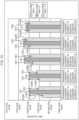
- Fig. 10 is a view illustrating the embodiment of the present invention and illustrating one example of the SN ratio information 141 stored in the storage unit 140 in Fig. 1 .
- a first level value to a sixth level value are illustrated, which indicates that as the value of k of a kth level value increases, the SN ratio increases.
- Fig. 10 illustrates, as the SN ratio information 141, information relating to SN ratios acquired while changing the value of m in m pieces of the ultrasonic elements 111 relating to the reception ultrasonic elements 114 relative to n pieces of the ultrasonic elements 111 relating to transmission ultrasonic elements 112. Concretely, in Fig.
- Fig. 10 illustrates pieces of information relating to SN ratios in the cases where as m pieces of the ultrasonic elements 111 relating to the reception ultrasonic elements 114, 12 pieces of the ultrasonic elements 111 with the element numbers of 27 ch to 38 ch are used, 24 pieces of the ultrasonic elements 111 with the element numbers of 21 ch to 44 ch are used (namely, the ultrasonic elements 111 that are the same as the transmission ultrasonic elements 112 are used), 32 pieces of the ultrasonic elements 111 with the element numbers of 17 ch to 48 ch are used, 48 pieces of the ultrasonic elements 111 with the element numbers of 9 ch to 56 ch are used, and 64 pieces of the ultrasonic elements 111 with the element numbers of 1 ch to 64 ch are used.
- 10 also illustrates a difference between the first SN ratio 1001 and the second SN ratio 1002 and a difference between the first SN ratio 1001 and the third SN ratio 1003 in each of the cases where the value of m in m pieces of the ultrasonic elements 111 relating to the reception ultrasonic elements 114 is changed to 12, 24, 32, 48, and 64, which are described above.
- the reception ultrasonic element setting unit 122 uses the SN ratio information 141 stored in the storage unit 140 to set the reception ultrasonic elements 114 consisting of m pieces of the ultrasonic elements 111. Concrete setting examples of the reception ultrasonic elements 114 by the reception ultrasonic element setting unit 122 will be described later using Fig. 14 to Fig. 17 .
- Fig. 11 is a flowchart illustrating one example of the processing procedures of the defect detection method by the defect detection device 100 according to this embodiment of the present invention.
- the transmission/reception control unit 123 sets a focusing region number R indicating the number of focusing regions where the ultrasonic beams 113 are focused in the thickness direction of the welded steel pipe 200 based on input information input from the input unit 150, for example.
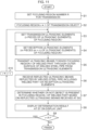
- Fig. 12A to Fig. 12C each are a view illustrating a first example of the case where the defect detection device 100 according to the embodiment of the present invention performs defect detection processing by focusing the ultrasonic beams 113 on a predetermined focusing region in the thickness direction of the welded steel pipe 200.
- Fig. 12A to Fig. 12C illustrate the case where the welded steel pipe 200 in the thickness direction is divided into three focusing regions r1 to r3 to scan the ultrasonic beams 113, and in this case, at Step S1 in Fig. 11 described above, the focusing region number R is set to three.
- Fig. 12A illustrates the case where the transmission ultrasonic elements 112 consisting of n pieces of the ultrasonic elements 111 on the side with small element numbers (ch 1 side) of the phased array probe 110 transmit the ultrasonic beams 113 in order to perform the defect detection processing of the focusing region r1 located near the outer surface 200G of the welded steel pipe 200 out of the three focusing regions r1 to r3.
- Fig. 12A illustrates the case where the transmission ultrasonic elements 112 consisting of n pieces of the ultrasonic elements 111 on the side with small element numbers (ch 1 side) of the phased array probe 110 transmit the ultrasonic beams 113 in order to perform the defect detection processing
- FIG. 12B illustrates the case where the transmission ultrasonic elements 112 consisting of n pieces of the ultrasonic elements 111 near the center of the phased array probe 110 transmit the ultrasonic beams 113 in order to perform the defect detection processing of the focusing region r2 located at the center portion of the welded steel pipe 200 in the thickness direction out of the three focusing regions r1 to r3. Further, Fig.
- FIG. 12C illustrates the case where the transmission ultrasonic elements 112 consisting of n pieces of the ultrasonic elements 111 on the side with large element numbers (ch N side) of the phased array probe 110 transmit the ultrasonic beams 113 in order to perform the defect detection processing of the focusing region r3 located near the inner surface 200N of the welded steel pipe 200 out of the three focusing regions r1 to r3. That is, the first example illustrated in Fig. 12A to Fig. 12C illustrates the case of scanning the ultrasonic beams 113 in each of the focusing regions r1 to r3 in the thickness direction of the welded steel pipe 200 by sequentially changing the position of the transmission ultrasonic element 112 in the phased array probe 110.
- a mode in which the SN ratio information 141 illustrated in Fig. 10 is stored in the storage unit 140 in Fig. 1 according to each of the focusing regions r1 to r3 is employed.
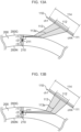
- Fig. 13A to Fig. 13C each are a view illustrating a second example in the case where the defect detection device 100 according to the embodiment of the present invention performs the defect detection processing by focusing the ultrasonic beams 113 on a predetermined focusing region in the thickness direction of the welded steel pipe 200.
- Fig. 13A to Fig. 13C also illustrate the case where the welded steel pipe 200 in the thickness direction is divided into the three focusing regions r1 to r3 similarly to the above-described case of Fig. 12A to Fig. 12C to scan the ultrasonic beams 113, and in this case, at Step S1 in Fig. 11 described above, the focusing region number R is set to three. Concretely, Fig.
- FIG. 13A illustrates the case where the transmission ultrasonic elements 112 consisting of n pieces of the ultrasonic elements 111 near the center of the phased array probe 110 transmit the ultrasonic beams 113 while adjusting the transmission delay pattern 410 in order to perform the defect detection processing of the focusing region r1 located near the outer surface 200G of the welded steel pipe 200 out of the three focusing regions r1 to r3. Further, Fig.
- FIG. 13B illustrates the case where the transmission ultrasonic elements 112 consisting of n pieces of the ultrasonic elements 111 near the center of the phased array probe 110 transmit the ultrasonic beams 113 while adjusting the transmission delay pattern 410 in order to perform the defect detection processing of the focusing region r2 located at the center portion of the welded steel pipe 200 in the thickness direction out of the three focusing regions r1 to r3. Further, Fig.
- FIG. 13C illustrates the case where the transmission ultrasonic elements 112 consisting of n pieces of the ultrasonic elements 111 near the center of the phased array probe 110 transmit the ultrasonic beams 113 while adjusting the transmission delay pattern 410 in order to perform the defect detection processing of the focusing region r3 located near the inner surface 200N of the welded steel pipe 200 out of the three focusing regions r1 to r3. That is, the second example illustrated in Fig. 13A to Fig.
- 13C illustrates the case of scanning the ultrasonic beams 113 in each of the focusing regions r1 to r3 in the thickness direction of the welded steel pipe 200 by fixing the position of the transmission ultrasonic elements 112 in the phased array probe 110 to the center portion and sequentially changing the transmission delay pattern 410.
- a mode in which the SN ratio information 141 illustrated in Fig. 10 is stored in the storage unit 140 in Fig. 1 according to each of the focusing regions r1 to r3 is employed.
- the transmission/reception control unit 123 sets one as a variable r representing the focusing region as a transmission object in the thickness direction of the welded steel pipe 200. Thereby, one is set as the focusing region r of a transmission object.
- the focusing region r1 illustrated in Fig. 12A is set, and in the case of the second example illustrated in Fig. 13A to Fig. 13C , the focusing region r1 illustrated in Fig. 13A is set.
- the transmission ultrasonic element setting unit 121 sets the transmission ultrasonic elements 112 in the focusing region r based on input information input from the input unit 150, for example.
- the transmission ultrasonic element setting unit 121 sets n pieces of the ultrasonic elements, being some of a plurality (N pieces in the example illustrated in Fig. 1 ) of the ultrasonic elements 111 composing the phased array probe 110, as the transmission ultrasonic elements 112.
- the reception ultrasonic element setting unit 122 uses the SN ratio information 141 of the focusing region r stored in the storage unit 140 to set the reception ultrasonic elements 114 in the focusing region r.
- the reception ultrasonic element setting unit 122 sets m pieces, being larger than n pieces, of the ultrasonic elements 111 including n pieces of the ultrasonic elements 111 relating to the transmission ultrasonic elements 112 as the reception ultrasonic elements 114.
- Concrete setting examples of the reception ultrasonic elements 114 by the reception ultrasonic element setting unit 122 will be explained later using Fig. 14 to Fig. 17 .
- the transmission unit 131 performs processing of transmitting the ultrasonic beams 113 toward the focusing region r of the welded part 210 through the outer surface 200G of the welded steel pipe 200 from the transmission ultrasonic elements 112 set at Step S3 based on control of the transmission/reception control unit 123.
- the transmission unit 131 makes the ultrasonic beams 113 directly incident on the welded part 210 substantially vertically without reflecting on the inner surface 200N of the welded steel pipe 200 as illustrated in Fig. 12A to Fig. 12C or Fig. 13A to Fig. 13C , for example.
- the reception unit 132 performs processing of receiving the reflected ultrasonic beams being the ultrasonic beams 113 reflected by the welded steel pipe 200 including the welded part 210 via the reception ultrasonic elements 114 set at Step S4 based on control of the transmission/reception control unit 123.
- the defect determination unit 124 determines whether or not the defect 211 is present in the focusing region r of the welded part 210 based on the reflected ultrasonic beams received at Step S6.
- the determination of the defect 211 based on the reflected ultrasonic beams performed by the defect determination unit 124 is a well-known art as described also in Patent Literature 1, for example, so that its detailed explanation is omitted. As one example, it is thought to determine whether or not the defect 211 is present in the focusing region r of the welded part 210 according to whether or not a signal based on the reflected ultrasonic beams has been received in a time zone region of the defect echos illustrated in Fig. 7 , for example.
- Step S8 the display control unit 125 performs a control to display a determination result regarding whether or not the defect 211 is present, which is obtained at Step S7, on the display unit 160.
- the transmission/reception control unit 123 determines whether or not the variable r representing the focusing region as a transmission object is less than the focusing region number R set at Step S1.
- Step S9 when the variable r representing the focusing region as a transmission object is less than the focusing region number R set at Step S1 (S9/YES), it is determined that the defect detection processings of all the focusing regions are not yet performed, and then proceed to Step S10.
- the transmission/reception control unit 123 adds one to the variable r representing the focusing region as a transmission object in the thickness direction of the welded steel pipe 200. Thereby, the focusing region r as a new transmission object is set. Thereafter, returning to Step S3, the processings at and after Step S3 are performed on the focusing region r newly set at Step S10.
- Step S9 when the variable r representing the focusing region as a transmission object is not less than the focusing region number R set at Step S1 (S9/NO), it is determined that the defect detection processings of all the focusing regions are performed, and then the processings of the flowchart in Fig. 11 are finished.
- Fig. 14 is a flowchart illustrating one example of detailed processing procedures of first setting processing of the reception ultrasonic elements 114 at Step S4 in Fig. 11 .
- the reception ultrasonic element setting unit 122 acquires the SN ratio information corresponding to n pieces of the ultrasonic elements relating to the transmission ultrasonic elements 112 set at Step S3 in Fig. 11 from the SN ratio information 141 stored in the storage unit 140.
- the reception ultrasonic element setting unit 122 extracts values of m that enable the first SN ratio to be equal to or more than a predetermined threshold value from the SN ratio information acquired at Step S411.
- m 24, 32, 48, and 64 are extracted as the value of m that enables the first SN ratio 1001 to be equal to or more than a fourth level value being a predetermined threshold value.
- the fourth level value set as a predetermined threshold value is one example of the SN ratio determined from the viewpoint of accuracy of detecting the defect 211.
- the reception ultrasonic element setting unit 122 selects, from the values of m extracted at Step S412, the value of m that enables at least one of the difference between the first SN ratio and a second SN ratio and the difference between the first SN ratio and a third SN ratio to be the smallest.
- the value of m that enables at least one of the difference between the first SN ratio 1001 and the second SN ratio 1002 and the difference between the first SN ratio 1001 and the third SN ratio 1003 to be the smallest is selected.
- the reception ultrasonic element setting unit 122 sets m pieces, being larger than n pieces, of the ultrasonic elements 111 including n pieces of the ultrasonic elements 111 relating to the transmission ultrasonic elements 112 as the reception ultrasonic elements 114 based on the value of m selected at Step S413.
- Fig. 15 is a flowchart illustrating one example of detailed processing procedures of second setting processing of the reception ultrasonic elements 114 at Step S4 in Fig. 11 .
- the reception ultrasonic element setting unit 122 acquires the SN ratio information corresponding to n pieces of the ultrasonic elements relating to the transmission ultrasonic elements 112 set at Step S3 in Fig. 11 from the SN ratio information 141 stored in the storage unit 140.
- the reception ultrasonic element setting unit 122 extracts values of m that enable the first SN ratio, the second SN ratio, and the third SN ratio to be equal to or more than a predetermined threshold value from the SN ratio information acquired at Step S411.
- the fourth level value set as a predetermined threshold value is one example of the SN ratio determined from the viewpoint of accuracy of detecting the defect 211.
- the reception ultrasonic element setting unit 122 selects, from the values of m extracted at Step S421, the value of m that enables at least one of the difference between the first SN ratio and the second SN ratio and the difference between the first SN ratio and the third SN ratio to be the smallest.
- the value of m that enables at least one of the difference between the first SN ratio 1001 and the second Sn ratio 1002 and the difference between the first SN ratio 1001 and the third SN ratio 1003 to be the smallest is selected.
- the reception ultrasonic element setting unit 122 sets m pieces, being larger than n pieces, of the ultrasonic elements 111 including n pieces of the ultrasonic elements 111 relating to the transmission ultrasonic elements 112 as the reception ultrasonic elements 114 based on the value of m selected at Step S422.
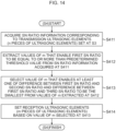
- Fig. 16 is a flowchart illustrating one example of detailed processing procedures of third setting processing of the reception ultrasonic elements 114 at Step S4 in Fig. 11 .
- the reception ultrasonic element setting unit 122 acquires the SN ratio information corresponding to n pieces of the ultrasonic elements relating to the transmission ultrasonic elements 112 set at Step S3 in Fig. 11 from the SN ratio information 141 stored in the storage unit 140.
- the reception ultrasonic element setting unit 122 extracts values of m that enable the first SN ratio to be equal to or more than a predetermined threshold value from the SN ratio information acquired at Step S411.
- m 24, 32, 48, and 64 are extracted as the value of m that enables the first SN ratio 1001 to be equal to or more than the fourth level value being a predetermined threshold value.
- the reception ultrasonic element setting unit 122 selects, from the values of m extracted at Step S412, the value of m that enables the sum of the difference between the first SN ratio and the second SN ratio and the difference between the first SN ratio and the third SN ratio to be the smallest.
- the value of m that enables the sum of the difference between the first SN ratio 1001 and the second SN ratio 1002 and the difference between the first SN ratio 1001 and the third SN ratio 1003 to be the smallest is selected. Concretely, in the example illustrated in Fig.
- the reception ultrasonic element setting unit 122 sets m pieces, being larger than n pieces, of the ultrasonic elements 111 including n pieces of the ultrasonic elements 111 relating to the transmission ultrasonic elements 112 as the reception ultrasonic elements 114 based on the value of m selected at Step S431.
- the processing at Step S432 is finished, the third setting processing of the reception ultrasonic elements 114 illustrated in Fig. 16 is finished.
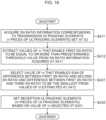
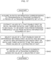
- Fig. 17 is a flowchart illustrating one example of detailed processing procedures of fourth setting processing of the reception ultrasonic elements 114 at Step S4 in Fig. 11 .
- the reception ultrasonic element setting unit 122 acquires the SN ratio information corresponding to n pieces of the ultrasonic elements relating to the transmission ultrasonic elements 112 set at Step S3 in Fig. 11 from the SN ratio information 141 stored in the storage unit 140.
- the reception ultrasonic element setting unit 122 extracts values of m that enable the first SN ratio, the second SN ratio, and the third SN ratio to be equal to or more than a predetermined threshold value from the SN ratio information acquired at Step S411.
- the reception ultrasonic element setting unit 122 selects, from the values of m extracted at Step S421, the value of m that enables the sum of the difference between the first SN ratio and the second SN ratio and the difference between the first SN ratio and the third SN ratio to be the smallest.
- the value of m that enables the sum of the difference between the first SN ratio 1001 and the second SN ratio 1002 and the difference between the first SN ratio 1001 and the third SN ratio 1003 to be the smallest is selected. Concretely, in the example illustrated in Fig.
- the reception ultrasonic element setting unit 122 sets m pieces, being larger than n pieces, of the ultrasonic elements 111 including n pieces of the ultrasonic elements 111 relating to the transmission ultrasonic elements 112 as the reception ultrasonic elements 114 based on the value of m selected at Step S441.
- the fourth setting processing of the reception ultrasonic elements 114 illustrated in Fig. 17 is finished.
- the SN ratio information 141 illustrated in Fig. 10 is the SN ratio information in the case where the ultrasonic beams 113 are transmitted to the center portion of the calibration pipe 300 in the thickness direction as illustrated in Fig. 9A , and thus corresponds to the SN ratio information to be used for performing the defect detection processing of the focusing region r2 illustrated in Fig. 12B or Fig. 13B .
- FIG. 13C can be different from the SN ratio information used for performing the defect detection processing of the focusing region r2 illustrated in Fig. 10 .
- the relationship between the element number n of the transmission ultrasonic elements 112 and the element number m of the reception ultrasonic elements 114 can be different from that of the case of the focusing region r2 illustrated in Fig. 10 (namely, there is a possibility that m changes).
- Fig. 12A to Fig. 12C and Fig. 13A to Fig. 13C above illustrate the example where the focusing region number R is three, but this embodiment is not limited to this mode, and for example, a mode in which plural numbers other than three are used as the focusing region number R is also applicable to this embodiment.
- the defect detection device 100 is designed so that the transmission unit 131 sets n pieces of the ultrasonic elements 111, being some of a plurality of the ultrasonic elements 111 composing the phased array probe 110, as the transmission ultrasonic elements 112 to transmit the ultrasonic beams 113 toward the welded part 210 through the outer surface 200G of the welded steel pipe 200 from the transmission ultrasonic elements 112.
- the reception ultrasonic element setting unit 122 sets m pieces, being larger than n pieces, of the ultrasonic elements 111 including n pieces of the ultrasonic elements relating to the transmission ultrasonic elements 112 as the reception ultrasonic elements 114 in consideration of the SN ratio relating to the reflected ultrasonic beams in the case where the welded part 210 is displaced in the circumferential direction of the welded steel pipe 200 relative to the phased array probe 110 (concretely, with reference to the SN ratio information 141 stored in the storage unit 140 (for example, the SN ratio information illustrated in Fig. 10 )).
- the reception unit 132 receives the reflected ultrasonic beams being the ultrasonic beams 113 reflected by the welded steel pipe 200 including the welded part 210 via the reception ultrasonic elements 114 and the defect determination unit 124 determines whether or not the defect 211 is present in the welded part 210 based on the reflected ultrasonic beams received by the reception unit 132.
- the reception ultrasonic elements 114 are set in consideration of the SN ratio relating to the reflected ultrasonic beams in the case where the welded part 210 is displaced in the circumferential direction of the welded steel pipe 200 relative to the phased array probe 110, so that as has been explained using Fig. 10 , it is possible to suppress the decrease in accuracy of detecting the defect 211 in the case where the position of the welded part 210 is displaced in the circumferential direction of the welded steel pipe 200 from an expected position.
- the reception ultrasonic element setting unit 122 sets m pieces, being larger than n pieces, of the ultrasonic elements 111 including n pieces of the ultrasonic elements relating to the transmission ultrasonic elements 112 as the reception ultrasonic elements 114 in consideration of the SN ratio relating to the reflected ultrasonic beams in the case where the welded part 210 is displaced in the circumferential direction of the welded steel pipe 200 relative to the phased array probe 110 (concretely, with reference to the SN ratio information 141 stored in the storage unit 140 (for example, the SN ratio information illustrated in Fig. 10 )).
- the present invention is not limited to this mode.
- an echo height relating to the reflected ultrasonic beams is applicable.
- the case where the echo height relating to the reflected ultrasonic beams is applied will be explained.
- a mode in which the storage unit 140 illustrated in Fig. 1 stores echo height information in place of the SN ratio information 141 is employed.
- the echo height is employed in place of the SN ratio.
- this echo height is the same in concept as the echo height illustrated at the vertical axis in Fig. 8 and Fig. 9B to Fig. 9D .
- the reception ultrasonic element setting unit 122 acquires echo height information corresponding to n pieces of the ultrasonic elements relating to the transmission ultrasonic elements 112 set at Step S3 in Fig. 11 from the echo height information applied in place of the SN ratio information 141 stored in the storage unit 140.
- Step S3 in Fig. 11 24 pieces of the ultrasonic elements 111 with the element numbers of 21 ch to 44 ch are set as the transmission ultrasonic elements 112, so that the echo height information applied in place of the SN ratio information illustrated in Fig.
- the reception ultrasonic element setting unit 122 extracts values of m that enable a first echo height applied in place of the above-described first SN ratio to be equal to or more than a predetermined threshold value from the echo height information acquired at Step S411.
- m 24, 32, 48, and 64 are extracted as the value of m that enables the first echo height applied in place of the first SN ratio 1001 illustrated in Fig. 10 to be equal to or more than a fourth level value being a predetermined threshold value.
- the fourth level value set as a predetermined threshold value is one example of the echo height determined from the viewpoint of accuracy of detecting the defect 211.
- the reception ultrasonic element setting unit 122 selects, from the values of m extracted at Step S412, the value of m that enables at least one of the difference between the first echo height applied in place of the first SN ratio and a second echo height applied in place of the second SN ratio and the difference between the first echo height and a third echo height applied in place of the third SN ratio to be the smallest.
- the value of m that enables at least one of the difference between the first echo height applied in place of the first SN ratio and a second echo height applied in place of the second SN ratio and the difference between the first echo height and a third echo height applied in place of the third SN ratio to be the smallest.
- the value of m that enables at least one of the difference between the first echo height applied in place of the first SN ratio 1001 and the second echo height applied in place of the second SN ratio 1002 and the difference between the first echo height applied in place of the first SN ratio 1001 and the third echo height applied in place of the third SN ratio 1003 to be the smallest is selected.
- the reception ultrasonic element setting unit 122 sets m pieces, being larger than n pieces, of the ultrasonic elements 111 including n pieces of the ultrasonic elements 111 relating to the transmission ultrasonic elements 112 as the reception ultrasonic elements 114 based on the value of m selected at Step S413.
- the reception ultrasonic element setting unit 122 acquires the echo height information corresponding to n pieces of the ultrasonic elements relating to the transmission ultrasonic elements 112 set at Step S3 in Fig. 11 from the echo height information applied in place of the SN ratio information 141 stored in the storage unit 140.
- the reception ultrasonic element setting unit 122 extracts values of m that enable the first echo height applied in place of the above-described first SN ratio, the second echo height applied in place of the second SN ratio, and the third echo height applied in place of the third SN ratio to be equal to or more than a predetermined threshold value from the echo height information acquired at Step S411.
- the fourth level value set as a predetermined threshold value is one example of the echo height determined from the viewpoint of accuracy of detecting the defect 211.
- the reception ultrasonic element setting unit 122 selects, from the values of m extracted at Step S421, the value of m that enables at least one of the difference between the first echo height applied in place of the first SN ratio and the second echo height applied in place of the second SN ratio and the difference between the first echo height and the third echo height applied in place of the third SN ratio to be the smallest.
- the value of m that enables at least one of the difference between the first echo height applied in place of the first SN ratio and the second echo height applied in place of the second SN ratio and the difference between the first echo height and the third echo height applied in place of the third SN ratio to be the smallest.
- the value of m that enables at least one of the difference between the first echo height applied in place of the first SN ratio 1001 and the second echo height applied in place of the second SN ratio 1002 and the difference between the first echo height applied in place of the first SN ratio 1001 and the third echo height applied in place of the third SN ratio 1003 to be the smallest is selected.
- the reception ultrasonic element setting unit 122 sets m pieces, being larger than n pieces, of the ultrasonic elements 111 including n pieces of the ultrasonic elements 111 relating to the transmission ultrasonic elements 112 as the reception ultrasonic elements 114 based on the value of m selected at Step S422.
- the reception ultrasonic element setting unit 122 acquires the echo height information corresponding to n pieces of the ultrasonic elements relating to the transmission ultrasonic elements 112 set at Step S3 in Fig. 11 from the echo height information applied in place of the SN ratio information 141 stored in the storage unit 140.
- the reception ultrasonic element setting unit 122 extracts values of m that enable the first echo height applied in place of the above-described first SN ratio to be equal to or more than a predetermined threshold value from the echo height information acquired at Step S411.
- m 24, 32, 48, and 64 are extracted as the value of m that enables the first echo height applied in place of the first SN ratio 1001 illustrated in Fig. 10 to be equal to or more than the fourth level value being a predetermined threshold value.
- the reception ultrasonic element setting unit 122 selects, from the values of m extracted at Step S412, the value of m that enables the sum of the difference between the first echo height applied in place of the first SN ratio and the second echo height applied in place of the second SN ratio and the difference between the first echo height and the third echo height applied in place of the third SN ratio to be the smallest.
- the value of m that enables the sum of the difference between the first echo height applied in place of the first SN ratio and the second echo height applied in place of the second SN ratio and the difference between the first echo height and the third echo height applied in place of the third SN ratio to be the smallest.
- the value of m that enables the sum of the difference between the first echo height applied in place of the first SN ratio 1001 and the second echo height applied in place of the second SN ratio 1002 and the difference between the first echo height applied in place of the first SN ratio 1001 and the third echo height applied in place of the third SN ratio 1003 to be the smallest is selected. Concretely, in the example illustrated in Fig.
- the reception ultrasonic element setting unit 122 sets m pieces, being larger than n pieces, of the ultrasonic elements 111 including n pieces of the ultrasonic elements 111 relating to the transmission ultrasonic elements 112 as the reception ultrasonic elements 114 based on the value of m selected at Step S431.
- the processing at Step S432 is finished, the third setting processing of the reception ultrasonic elements 114 illustrated in Fig. 16 is finished.
- the reception ultrasonic element setting unit 122 acquires the echo height information corresponding to n pieces of the ultrasonic elements relating to the transmission ultrasonic elements 112 set at Step S3 in Fig. 11 from the echo height information applied in place of the SN ratio information 141 stored in the storage unit 140.
- the reception ultrasonic elements setting unit 122 extracts values of m that enable the first echo height applied in place of the first SN ratio, the second echo height applied in place of the second SN ratio, and the third echo height applied in place of the third SN ratio to be equal to or more than a predetermined threshold value from the echo height information acquired at Step S411.
- the reception ultrasonic element setting unit 122 selects, from the values of m extracted at Step S421, the value of m that enables the sum of the difference between the first echo height applied in place of the first SN ratio and the second echo height applied in place of the second SN ratio and the difference between the first echo height and the third echo height applied in place of the third SN ratio to be the smallest.
- the value of m that enables the sum of the difference between the first echo height applied in place of the first SN ratio and the second echo height applied in place of the second SN ratio and the difference between the first echo height and the third echo height applied in place of the third SN ratio to be the smallest.
- the value of m that enables the sum of the difference between the first echo height applied in place of the first SN ratio 1001 and the second echo height applied in place of the second SN ratio 1002 and the difference between the first echo height applied in place of the first SN ratio 1001 and the third echo height applied in place of the third SN ratio 1003 to be the smallest is selected. Concretely, in the example illustrated in Fig.
- the reception ultrasonic element setting unit 122 sets m pieces, being larger than n pieces, of the ultrasonic elements 111 including n pieces of the ultrasonic elements 111 relating to the transmission ultrasonic elements 112 as the reception ultrasonic elements 114 based on the value of m selected at Step S441.
- the fourth setting processing of the reception ultrasonic elements 114 illustrated in Fig. 17 is finished.
- the present invention can be achieved also by processing in which a program implementing one or more functions of the above-described embodiment is supplied to a system or a device via a network or a storage medium and one or more processors in a computer of the system or the device read and execute the program. Further, the present invention can be achieved also by a circuit implementing one or more functions (for example, ASIC).
- the program and a computer-readable storage medium in which the program is stored are included in the present invention.
Description
- The present invention relates to a defect detection device and a defect detection method that detect a defect present in a welded part formed along a pipe longitudinal of a welded-steel pipe, and a program for causing a computer to execute this defect detection method.
- In a welded steel pipe such as an electric resistance welded steel pipe, the quality of a welded part (weld surface) is extremely important. As an art to determine whether or not a defect is present in a welded part of a welded steel pipe, there is an art described in
Patent Literature 1, for example. Concretely,Patent Literature 1 describes an art in which ultrasonic beams are transmitted toward a welded part through an outer surface of a welded steel pipe from a flaw detection ultrasonic element group consisting of some ultrasonic elements of a plurality of ultrasonic elements composing a phased array probe, the ultrasonic beams reflected by the welded steel pipe including the welded part are received via the flaw detection ultrasonic element group that has transmitted the ultrasonic beams, and based on the received ultrasonic beams, whether or not a defect is present in the welded part is determined.
Patent Literature 2 describes a defect detection device comprising a phased array probe, a transmitter, a receptor, and a defect determination unit.
Patent Literature 3 describes a calibration method of an ultrasonic flaw detection.
Patent Literature 4 describes an ultrasonic flaw detection apparatus for detecting a minute flaw generated in a welded portion of a welded steel pipe. -
- Patent Literature 1:
Japanese Laid-open Patent Publication No. 2016-38361 - Patent Literature 2:
WO 2014/007023 A1 - Patent Literature 3:
EP 2 116 847 A1 - Patent Literature 4:
EP 2 124 045 A1 - When performing a defect inspection of a welded part in a manufacturing process of a welded steel pipe, the position of the welded part is sometimes displaced in the circumferential direction of the welded steel pipe depending on the welded steel pipe. Regarding this point, in the art described in
Patent Literature 1, the reflected ultrasonic beams reflected by the welded steel pipe including the welded part are received by using the same ultrasonic element group as the ultrasonic element group that has transmitted the ultrasonic beams toward the welded part, so that it is difficult to properly receive the reflected ultrasonic beams from a defect present in the welded part in the case where the position of the welded part is displaced in the circumferential direction of the welded steel pipe from an expected position. That is, the art described inPatent Literature 1 has caused a problem that the accuracy of detecting the defect decreases in the case where the position of the welded part is displaced in the circumferential direction of the welded steel pipe from an expected position. - The present invention has been made in consideration of such problems, and an object thereof is to provide, when performing a defect inspection of a welded part of a welded steel pipe using a phased array probe, a mechanism capable of suppressing a decrease in accuracy of detecting a defect in the case where the position of the welded part is displaced in the circumferential direction of the welded steel pipe from an expected position.
- The present invention is defined in the claims. A defect detection device of the present invention is a defect detection device that detects a defect present in a welded part formed along a pipe longitudinal of a welded steel pipe, the device including: a phased array probe that is installed outside an outer surface of the welded steel pipe and includes a plurality of ultrasonic elements arranged therein; a transmission means configured to set n pieces of the ultrasonic elements, being some of a plurality of the ultrasonic elements composing the phased array probe, as transmission ultrasonic elements and transmits ultrasonic beams toward the welded part through the outer surface of the welded steel pipe from the transmission ultrasonic elements; a reception means configured to receive reflected ultrasonic beans being the ultrasonic beams reflected by the welded steel pipe including the welded part via reception ultrasonic elements consisting of m pieces, being larger than n pieces, of the ultrasonic elements including n pieces of the ultrasonic elements composing the transmission ultrasonic elements out of a plurality of the ultrasonic elements composing the phased array probe; and a defect determination means configured to determine whether or not a defect is present in the welded part based on the reflected ultrasonic beams received by the reception means.
- Further, the present invention includes a defect detection method by the above-described defect detection device and a program for causing a computer to execute this defect detection method.
- According to the present invention, it is possible to, when performing a defect inspection of a welded part of a welded steel pipe using a phased array probe, suppress a decrease in accuracy of detecting a defect in the case where the position of the welded part is displaced in the circumferential direction of the welded steel pipe from an expected position.
-
- [
Fig. 1] Fig. 1 is a view illustrating one example of a schematic configuration of a defect detection device according to an embodiment of the present invention. - [
Fig. 2A] Fig. 2A is a view illustrating the embodiment of the present invention and illustrating one example of a method of determining a position of a welded part illustrated inFig. 1 . - [
Fig. 2B] Fig. 2B is a view illustrating the embodiment of the present invention and illustrating one example of the method of determining the position of the welded part illustrated inFig. 1 . - [
Fig. 2C] Fig. 2C is a view illustrating the embodiment of the present invention and illustrating one example of the method of determining the position of the welded part illustrated inFig. 1 . - [
Fig. 3A] Fig. 3A is a view illustrating a state of the case where ultrasonic beams are transmitted to the position of the welded part determined by the method illustrated inFig. 2C from a phased array probe illustrated inFig. 1 . - [
Fig. 3B] Fig. 3B is a view illustrating a state of the case where ultrasonic beams are transmitted to the position of the welded part determined by the method illustrated inFig. 2C from the phased array probe illustrated inFig. 1 . - [
Fig. 4] Fig. 4 is a view illustrating the embodiment of the present invention and illustrating setting examples of a transmission delay pattern of transmission ultrasonic elements relating to transmission of ultrasonic beams and a reception delay pattern of reception ultrasonic elements relating to reception of reflected ultrasonic beams by a transmission/reception control unit inFig. 1 . - [
Fig. 5] Fig. 5 is a view illustrating the embodiment of the present invention and illustrating a state of transmitting ultrasonic beams toward a calibration pipe for calibrating a welded steel pipe inFig. 1 from the phased array probe inFig. 1 . - [
Fig. 6] Fig. 6 is a view illustrating a reference example and illustrating an SN ratio relating to reflected ultrasonic beams from an artificial defect in the case where a number n of the transmission ultrasonic elements illustrated inFig. 5 is changed sequentially and the reception ultrasonic elements are the same as the transmission ultrasonic elements. - [
Fig. 7] Fig. 7 is a view illustrating the embodiment of the present invention and illustrating a B scanned image relating to the reflected ultrasonic beam received by each ultrasonic element of the phased array probe in which the number n of the transmission ultrasonic elements illustrated inFig. 5 is set to a predetermined number. - [
Fig. 8] Fig. 8 is a view illustrating the embodiment of the present invention and in which the maximum signal intensity of defect echos received by the ultrasonic elements (with element numbers of 1 ch to 64 ch) of the phased array probe in the case ofFig. 7 is illustrated as a defect echo height. - [
Fig. 9A] Fig. 9A is a view illustrating the embodiment of the present invention and illustrating one example of acquisition processing of SN ratio information stored in a storage unit inFig. 1 . - [
Fig. 9B] Fig. 9B is a view illustrating the embodiment of the present invention and illustrating one example of the acquisition processing of the SN ratio information stored in the storage unit inFig. 1 . - [
Fig. 9C] Fig. 9C is a view illustrating the embodiment of the present invention and illustrating one example of the acquisition processing of the SN ratio information stored in the storage unit inFig. 1 . - [
Fig. 9D] Fig. 9D is a view illustrating the embodiment of the present invention and illustrating one example of the acquisition processing of the SN ratio information stored in the storage unit inFig. 1 . - [
Fig. 10] Fig. 10 is a view illustrating the embodiment of the present invention and illustrating one example of the SN ratio information stored in the storage unit inFig. 1 . - [
Fig. 11] Fig. 11 is a flowchart illustrating one example of processing procedures of a defect detection method by the defect detection device according to the embodiment of the present invention. - [
Fig. 12A] Fig. 12A is a view illustrating a first example of the case where the defect detection device according to the embodiment of the present invention performs defect detection processing by focusing ultrasonic beams on a predetermined focusing region in a thickness direction of the welded steel pipe. - [
Fig. 12B] Fig. 12B is a view illustrating the first example of the case where the defect detection device according to the embodiment of the present invention performs the defect detection processing by focusing ultrasonic beams on a predetermined focusing region in the thickness direction of the welded steel pipe. - [
Fig. 12C] Fig. 12C is a view illustrating the first example of the case where the defect detection device according to the embodiment of the present invention performs the defect detection processing by focusing ultrasonic beams on a predetermined focusing region in the thickness direction of the welded steel pipe. - [
Fig. 13A] Fig. 13A is a view illustrating a second example of the case where the defect detection device according to the embodiment of the present invention performs the defect detection processing by focusing ultrasonic beams on a predetermined focusing region in the thickness direction of the welded steel pipe. - [
Fig. 13B] Fig. 13B is a view illustrating the second example of the case where the defect detection device according to the embodiment of the present invention performs the defect detection processing by focusing ultrasonic beams on a predetermined focusing region in the thickness direction of the welded steel pipe. - [
Fig. 13C] Fig. 13C is a view illustrating the second example of the case where the defect detection device according to the embodiment of the present invention performs the defect detection processing by focusing ultrasonic beams on a predetermined focusing region in the thickness direction of the welded steel pipe. - [Fig. 141
Fig. 14 is a flowchart illustrating one example of detailed processing procedures of first setting processing of the reception ultrasonic elements at Step S4 inFig. 11 . - [
Fig. 15] Fig. 15 is a flowchart illustrating one example of detailed processing procedures of second setting processing of the reception ultrasonic elements at Step S4 inFig. 11 . - [
Fig. 16] Fig. 16 is a flowchart illustrating one example of detailed processing procedures of third setting processing of the reception ultrasonic elements at Step S4 inFig. 11 . - [
Fig. 17] Fig. 17 is a flowchart illustrating one example of detailed processing procedures of fourth setting processing of the reception ultrasonic elements at Step S4 inFig. 11 . - Hereinafter, there will be explained a mode for implementing the present invention (embodiment) with reference to the drawings.
-
Fig. 1 is a view illustrating one example of a schematic configuration of adefect detection device 100 according to the embodiment of the present invention. Thisdefect detection device 100 is a device for detecting adefect 211 present in a welded part (weld surface) 210 formed along a pipe longitudinal of a weldedsteel pipe 200 such as an electric resistance welded steel pipe. Further,Fig. 1 illustrates a cross section of the welded steel pipe 200 (the vicinity of a weldedpart 210 of the cross section of the welded steel pipe in more detail). Incidentally, the example where thedefect 211 is present inside the weldedpart 210 is illustrated inFig. 1 in order to make the explanation easily understandable, but depending on the weldedsteel pipe 200, thedefect 211 is sometimes not present inside the weldedpart 210. Further, in this embodiment, the outside diameter of the weldedsteel pipe 200 is preferably 38.1 mm to 114.3 mm, for example, and the thickness (the length between anouter surface 200G and aninner surface 200N) of the weldedsteel pipe 200 is preferably 1.6 mm to 10 mm, for example. - The
defect detection device 100 according to this embodiment is configured to include a phasedarray probe 110, a control andprocessing unit 120, a transmission/reception unit 130, astorage unit 140, aninput unit 150, and adisplay unit 160 as illustrated inFig. 1 . - The phased
array probe 110 is installed outside theouter surface 200G of the weldedsteel pipe 200 and is formed by having a plurality ofultrasonic elements 111 arranged therein. Concretely,Fig. 1 illustrates an example where as a plurality of theultrasonic elements 111 composing the phasedarray probe 110, N pieces of ultrasonic elements withch 1 to ch N are formed. Further,Fig. 1 illustrates, out of a plurality of theultrasonic elements 111 composing the phasedarray probe 110, transmissionultrasonic elements 112 that transmitultrasonic beams 113 toward the weldedpart 210 through theouter surface 200G of the weldedsteel pipe 200. On this occasion, theultrasonic beams 113 illustrated inFig. 1 are illustrated so as to focus on one point of the weldedpart 210, but this merely illustrates a path in terms of setting, and it is actually possible that theultrasonic beams 113 do not focus on one point of the weldedpart 210 depending on the specifications of the phased array probe 110 (for example, the width, frequency, number, or the like of the ultrasonic element 111). Therefore, in this embodiment, in the thickness direction of the weldedsteel pipe 200, a portion where theultrasonic beams 113 focus on the weldedpart 210 is described as a focusing region. Further,Fig. 1 illustrates, out of a plurality of theultrasonic elements 111 composing the phasedarray probe 110, receptionultrasonic elements 114 that receive reflected ultrasonic beams being theultrasonic beams 113 reflected by the weldedsteel pipe 200 including the welded part 210 (to be sometimes described as "reflected ultrasonic beams" simply below). Further, between the phasedarray probe 110 and theouter surface 200G of the weldedsteel pipe 200, for example, water exists as a medium for efficiently propagating theultrasonic beams 113. - The control and
processing unit 120 controls configuration units of thedefect detection device 100 and integrally controls operations of thedefect detection device 100 based on input information input from theinput unit 150, for example. Further, the control andprocessing unit 120 performs various pieces of processing based on input information input from theinput unit 150, for example. The control andprocessing unit 120 is configured to include a transmission ultrasonicelement setting unit 121, a reception ultrasonicelement setting unit 122, a transmission/reception control unit 123, adefect determination unit 124, and adisplay control unit 125 as illustrated inFig. 1 . - The transmission ultrasonic
element setting unit 121 sets n pieces of the ultrasonic elements, being some of a plurality of the ultrasonic elements 111 (N pieces in the example illustrated inFig. 1 ) composing the phasedarray probe 110, as the transmissionultrasonic elements 112 based on input information input from theinput unit 150, for example. - The reception ultrasonic
element setting unit 122 sets, out of a plurality of theultrasonic elements 111 composing the phasedarray probe 110, m pieces, being larger than n pieces, of the ultrasonic elements including n pieces of the ultrasonic elements relating to the transmissionultrasonic elements 112 as the receptionultrasonic elements 114 based on input information input from theinput unit 150, for example. On this occasion, the reception ultrasonicelement setting unit 122 sets the receptionultrasonic elements 114 in consideration ofSN ratio information 141 stored in thestorage unit 140. - The transmission/
reception control unit 123 controls the transmission/reception unit 130 based on input information input from theinput unit 150 and information set in the transmission ultrasonicelement setting unit 121 and the reception ultrasonicelement setting unit 122, for example. Concretely, the transmission/reception control unit 123 controls atransmission unit 131 in the transmission/reception unit 130 to cause the transmissionultrasonic elements 112 set by the transmission ultrasonicelement setting unit 121 to transmit theultrasonic beams 113. Further, the transmission/reception control unit 123 controls areception unit 132 in the transmission/reception unit 130 to cause the receptionultrasonic elements 114 set by the reception ultrasonicelement setting unit 122 to receive the reflected ultrasonic beams. - The
defect determination unit 124 determines whether or not thedefect 211 is present in the weldedpart 210 based on the reflected ultrasonic beams received by thereception unit 132 in the transmission/reception unit 130. - The
display control unit 125 performs a control of displaying a determination result of thedefect 211 by thedefect determination unit 124 on thedisplay unit 160. Further, thedisplay control unit 125 performs a control of displaying various pieces of information on thedisplay unit 160 as necessary. - The transmission/
reception unit 130 transmits and receives ultrasonic beams to and from the weldedsteel pipe 200 based on the control of the transmission/reception control unit 123. The transmission/reception unit 130 is configured to include thetransmission unit 131 and thereception unit 132. Thetransmission unit 131 performs processing to transmit theultrasonic beams 113 from the transmissionultrasonic elements 112 set by the transmission ultrasonicelement setting unit 121 out of a plurality of theultrasonic elements 111 composing the phasedarray probe 110. In this embodiment, thetransmission unit 131 performs processing to transmit theultrasonic beams 113 from the transmissionultrasonic elements 112 to make theultrasonic beams 113 that have entered the welded steel pipe through theouter surface 200G of the weldedsteel pipe 200 directly incident on the weldedpart 210 substantially vertically without reflecting on theinner surface 200N of the weldedsteel pipe 200 to focus on the weldedpart 210 based on the control of the transmission/reception control unit 123. Concretely, in this embodiment, thetransmission unit 131 transmits theultrasonic beam 113 from the transmissionultrasonic element 112 to refract theultrasonic beam 113 at an angle θ (about 70° in the example illustrated inFig. 1 ) relative to anincident axis 113a on theouter surface 200G of the weldedsteel pipe 200 and make it directly incident on the weldedpart 210 substantially vertically without reflecting on theinner surface 200N of the weldedsteel pipe 200. Further, thereception unit 132 performs processing to receive the reflected ultrasonic beams via the receptionultrasonic elements 114 set by the reception ultrasonicelement setting unit 122 out of a plurality of theultrasonic elements 111 composing the phasedarray probe 110. - The
storage unit 140 stores theSN ratio information 141 to be used when the reception ultrasonicelement setting unit 122 sets the receptionultrasonic element 114. TheSN ratio information 141 will be described later usingFig. 10 . Further, thestorage unit 140 stores various pieces of information, programs, and so on to be used in the control andprocessing unit 120 and various pieces of information and so on obtained by processing of the control andprocessing unit 120. - The
input unit 150 inputs input information operation input by a user, for example, to the control andprocessing unit 120. - The
display unit 160 displays a determination result of thedefect 211 by thedefect determination unit 124 based on the control of thedisplay control unit 125. Further, thedisplay unit 160 displays various pieces of information based on the control of thedisplay control unit 125. - Next, there will be explained positional displacement of the welded
part 210 in the circumferential direction of the weldedsteel pipe 200 usingFig. 2A to Fig. 2C andFig. 3A and Fig. 3B . -
Fig. 2A to Fig. 2C each are a view illustrating the embodiment of the present invention and illustrating one example of a method of determining the position of the weldedpart 210 illustrated inFig. 1 .Fig. 2A is a schematic view illustrating one example of the case where for example, a band-shaped steel sheet (band steel) is welded at the weldedpart 210 to manufacture the weldedsteel pipe 200. As illustrated inFig. 2A , at the time of welding, protuberant portions called beads are formed on the weldedpart 210. -
Fig. 2B is a view illustrating a state where the beads illustrated inFig. 2A are cut, light irradiation is performed on a cutting surface, and then a line camera photographs the cutting surface as one example for determining the position of the weldedpart 210. Further,Fig. 2C is a view illustrating one example of a intensity profile of an image of the cutting surface photographed by the line camera illustrated inFig. 2B . On this occasion, at the center point of the cutting surface, the intensity decreases due to the reason that the emitted light more irregularly reflects or the like, so that in the example illustrated inFig. 2C , the position where the intensity most decreases is determined as the position of the weldedpart 210. That is,Fig. 2C illustrates an example where the center point of a cut width of the cutting surface is determined as the position of the weldedpart 210. The reason why the position of the weldedpart 210 is determined by the method illustrated inFig. 2A to Fig. 2C is because it is difficult to directly measure the position of the weldedpart 210 after cutting the beads and determine the position in many cases. -
Fig. 3A and Fig. 3B each are a view illustrating a state of the case where theultrasonic beams 113 are transmitted to the position of the weldedpart 210 determined by the method illustrated inFig. 2C from the phasedarray probe 110 illustrated inFig. 1 .Fig. 3A illustrates the case where the weldedpart 210 is actually located at the position (cut width center) of the weldedpart 210 determined by the method illustrated inFig. 2C . In the case illustrated inFig. 3A , the weldedpart 210 is actually located at the position of the weldedpart 210 determined by the method illustrated inFig. 2C , so that it is possible to set a focusingposition 113b of theultrasonic beams 113 at the actual position of the weldedpart 210 by performing a control so that theultrasonic beams 113 focus on the position of the weldedpart 210 determined by the method illustrated inFig. 2C . In contrast to this,Fig. 3B illustrates the case where the actual position of the weldedpart 210 is displaced in the circumferential direction of the weldedsteel pipe 200 from the position of the welded part 210 (cut width center) determined by the method illustrated inFig. 2C . In the case illustrated inFig. 3B , the actual position of the weldedpart 210 is displaced in the circumferential direction of the weldedsteel pipe 200 from the position of the weldedpart 210 determined by the method illustrated inFig. 2C , so that it is impossible to set the focusingposition 113b of theultrasonic beams 113 at the actual position of the weldedpart 210 when performing a control so that theultrasonic beams 113 focus on the position of the weldedpart 210 determined by the method illustrated inFig. 2C . Therefore, in the case illustrated inFig. 3B , a decrease in accuracy of detecting thedefect 211 is concerned. Then, in order to suppress the decrease in accuracy of detecting thedefect 211 in the case illustrated inFig. 3B , this embodiment is designed to set m pieces, being larger than n pieces, of the ultrasonic elements including n pieces of the ultrasonic elements relating to the transmissionultrasonic elements 112 as the receptionultrasonic elements 114 by the reception ultrasonicelement setting unit 122. - Next, there will be explained setting of a transmission delay pattern of the transmission
ultrasonic elements 112 relating to the transmission of theultrasonic beams 113 by the transmission/reception control unit 123 and setting of a reception delay pattern of the receptionultrasonic elements 114 relating to the reception of the reflected ultrasonic beams by the transmission/reception control unit 123 usingFig. 4 . -
Fig. 4 is a view illustrating the embodiment of the present invention and illustrating a setting example of atransmission delay pattern 410 of the transmissionultrasonic elements 112 relating to the transmission of theultrasonic beams 113 by the transmission/reception control unit 123 inFig. 1 and a setting example of areception delay pattern 420 of the receptionultrasonic elements 114 relating to the reception of the reflected ultrasonic beams by the transmission/reception control unit 123 inFig. 1 . Incidentally, thetransmission delay pattern 410 and thereception delay pattern 420 that are illustrated inFig. 4 are merely one example, and are not limited to the mode illustrated inFig. 4 in this embodiment. - Concretely, the transmission/
reception control unit 123 sets thetransmission delay pattern 410 and thereception delay pattern 420 while considering the following factors, for example. - The number (n) of transmission
ultrasonic elements 112 - The number (m) of reception
ultrasonic elements 114 - The outside diameter of the welded
steel pipe 200 - The thickness (length between the
outer surface 200G and theinner surface 200N) of the weldedsteel pipe 200 - The geometric positional relationship between the phased
array probe 110 and the weldedsteel pipe 200 - The angle θ and the focusing
position 113b of theultrasonic beams 113 - The specifications (frequency, pitch, element number, element size, and so on) of the phased
array probe 110 - Physical property values of a medium (water) present between the phased
array probe 110 and theouter surface 200G of the welded steel pipe 200 (a sound propagation speed of theultrasonic beam 113, and so on) - Physical property values of a steel product of the welded steel pipe 200 (a sound propagation speed of the
ultrasonic beam 113, and so on) - Concretely, in this embodiment, the transmission/
reception control unit 123 sets thetransmission delay pattern 410 so as to refract theultrasonic beam 113 at the angle θ (about 70° in the example illustrated inFig. 4 ) relative to theincident axis 113a on theouter surface 200G of the weldedsteel pipe 200 and make it directly incident on the weldedpart 210 substantially vertically without reflecting on theinner surface 200N of the weldedsteel pipe 200. - On this occasion, the position of the phased
array probe 110 is set in the following manner, for example. - First, based on the determined focusing
position 113b of theultrasonic beams 113, a line orthogonal to the weldedpart 210 is extended toward theouter surface 200G of the weldedsteel pipe 200. Then, the line is extended in the direction of the phasedarray probe 110 at the angle of refraction θ based on Snell's law at theouter surface 200G of the weldedsteel pipe 200. Then, the phasedarray probe 110 is arranged so that the center of the phasedarray probe 110 can be located on the extension of the line and the extended line and an arrangement surface of theultrasonic elements 111 can intersect at right angles. - Further, the distance (water distance) between the phased
array probe 110 and theouter surface 200G of the weldedsteel pipe 200 is determined in consideration of an inspection time to be affected by a propagation time of the reflected ultrasonic beams from thedefect 211 present in the welded part 210 (in which the propagation time, namely, the inspection time becomes long when the water distance is long), the fact that the effect of reverberation echoes going and returning between the phasedarray probe 110 and theouter surface 200G of the weldedsteel pipe 200 is ignorable, or the like. - Next, there will be explained the
SN ratio information 141 stored in thestorage unit 140 usingFig. 5 to Fig. 10 . -
Fig. 5 is a view illustrating the embodiment of the present invention and illustrating a state of transmitting theultrasonic beams 113 to acalibration pipe 300 for calibrating the weldedsteel pipe 200 inFig. 1 from the phasedarray probe 110 inFig. 1 . Thecalibration pipe 300 illustrated inFig. 5 is a steel pipe for calibrating the weldedsteel pipe 200 illustrated inFig. 1 and is a steel pipe with anartificial defect 311 formed in a second weldedpart 310 equivalent to the weldedpart 210 of the weldedsteel pipe 200. On this occasion, as theartificial defect 311, a through hole having a predetermined size is formed. -
Fig. 6 is a view illustrating a reference example and illustrating an SN ratio relating to reflected ultrasonic beams from theartificial defect 311 in the case where a number n of the transmissionultrasonic elements 112 illustrated inFig. 5 is changed sequentially and the receptionultrasonic elements 114 are the same as the transmissionultrasonic elements 112. As for the SN ratio of the vertical axis inFig. 6 , a first level value to a sixth level value are illustrated, which indicates that as the value of k of a kth level value increases, the SN ratio increases. - Generally, the relationship of sound pressure sensitivity between the focusing-type phased
array probe 110 and the focusingposition 113b is thought that as the number of theultrasonic elements 111 to be driven (a transmission/reception ch number) is larger, the sound pressure sensitivity increases as long as the distance between the phasedarray probe 110 and the focusingposition 113b is fixed. That is, it is expected that as the number of theultrasonic elements 111 to be driven (the transmission/reception ch number) is larger, the SN ratio increases. However, inFig. 6 , as the number of theultrasonic elements 111 to be driven (the transmission/reception ch number) increases, the SN ratio increases to be maximum in a certain range, but as the number of theultrasonic elements 111 to be driven (the transmission/reception ch number) increases thereafter, the SN ratio decreases. This is thought because with the increase in the number of theultrasonic elements 111 to be driven (the transmission/reception ch number), theultrasonic elements 111 to be driven are increased in the direction going away from the center of the phasedarray probe 110, and thereby theultrasonic elements 111 increasing in excess of a certain range do not contribute to an improvement in the SN ratio but cause an increase in noise. Further, the angle at which the ultrasonic beam to be transmitted enters anouter surface 300G inFig. 5 varies according to the position of theultrasonic element 111 to be driven, and thereby reciprocating sound pressure penetration changes, which is also one cause (the penetration decreases in theultrasonic element 111 on an outer side where the incident angle increases (concretely in the direction toward ch N), for example). -
Fig. 7 is a view illustrating the embodiment of the present invention and illustrating a B scanned image relating to the reflected ultrasonic beams received by theultrasonic elements 111 of the phasedarray probe 110 in which the number n of the transmissionultrasonic elements 112 illustrated inFig. 5 is set to a predetermined number. Concretely, inFig. 7 , as the phasedarray probe 110, one composed of 64 pieces of theultrasonic elements 111 in total is used. Further, inFig. 7 , as the transmissionultrasonic elements Fig. 7 , theultrasonic beams 113 are transmitted from the transmissionultrasonic elements 112 at thetransmission delay pattern 410 set so that theultrasonic beams 113 focus on the center portion of thecalibration pipe 300 in the thickness direction at the angle of refraction θ = 70° . Then,Fig. 7 illustrates the B scanned image based on a waveform of the reflected ultrasonic beams received by the ultrasonic elements 111 (with element numbers of 1 ch to 64 ch) of the phasedarray probe 110 under the above-described conditions. - In
Fig. 7 , a colored portion in a region described as an outer surface echo indicates that theultrasonic elements 111 of the phasedarray probe 110 each have received the reflected ultrasonic beam from theouter surface 300G of thecalibration pipe 300. Further, inFig. 7 , a colored portion in a region described as a defect echo indicates that theultrasonic elements 111 of the phasedarray probe 110 each have received the reflected ultrasonic beam from theartificial defect 311 with φ 0.5 mm. -
Fig. 8 is a view illustrating the embodiment of the present invention and in which the maximum signal intensity of defect echos received by the ultrasonic elements 111 (with the element numbers of 1 ch to 64 ch) of the phasedarray probe 110 is illustrated as a defect echo height in the case ofFig. 7 . Concretely, inFig. 8 , the horizontal axis indicates the ultrasonic elements 111 (with the element numbers of 1 ch to 64 ch) of the phasedarray probe 110 and the vertical axis indicates the defect echo height. -
Fig. 8 reveals that a defect echo with a large signal intensity is observed at the ultrasonic transducers 111 (the element numbers of 21 ch to 44 ch) set as the transmissionultrasonic elements 112, while at the other ultrasonic elements 111 (ch 1 toch 20 andch 45 to ch 64) as well, a defect echo with a certain or more signal intensity is observed. From the above, it is inferred that in addition to theultrasonic elements 111 set as the transmissionultrasonic elements 112, theultrasonic elements 111 other than the transmissionultrasonic elements 112 are contained as the receptionultrasonic elements 114, thereby being able to contribute to an improvement in the SN ratio relating to the reflected ultrasonic beams from the artificial defect 311 (the defect echoes). -
Fig. 9A to Fig. 9D are views illustrating the embodiment of the present invention and illustrating one example of acquisition processing of theSN ratio information 141 stored in thestorage unit 140 inFig. 1 . -
Fig. 9A is a view illustrating a state of transmitting theultrasonic beams 113 to thecalibration pipe 300 for calibrating the weldedsteel pipe 200 inFig. 1 from the phasedarray probe 110 inFig. 1 . InFig. 9A , the same reference numerals and symbols are added to the same components as those illustrated inFig. 5 . Further,Fig. 9A also illustrates the case where the position of the second weldedpart 310 is displaced in the circumferential direction of thecalibration pipe 300, in which relative to the phasedarray probe 110, a reference position of the second weldedpart 310 is set as afirst position 901, a position where the position of the second weldedpart 310 is displaced clockwise from thefirst position 901 in the circumferential direction of thecalibration pipe 300 by an angle α (an angle +o; when the clockwise rotation is set as the + direction) is set as asecond position 902, and a position where the position of the second weldedpart 310 is displaced counterclockwise from thefirst position 901 in the circumferential direction of thecalibration pipe 300 by an angle β (an angle - β when the clockwise rotation is set as the + direction) is set as athird position 903. Further, the focusingposition 113b of theultrasonic beams 113 is set to be located at the second weldedpart 310 when the second weldedpart 310 is located at thefirst position 901. -
Fig. 9B is a view in which the maximum signal intensity of defect echos received by the ultrasonic elements 111 (with the element numbers of 1 ch to 64 ch) of the phasedarray probe 110 is indicated as a defect echo height when the second weldedpart 310 exists at thefirst position 901 illustrated inFig. 9A (namely, when a displacement angle from the reference position of the second weldedpart 310 relative to the phasedarray probe 110 is 0° ). InFig. 9B , similarly to the case ofFig. 8 , as the transmissionultrasonic elements ultrasonic elements 111 with the element numbers of 21 ch to 44 ch are used. -
Fig. 9C is a view in which the maximum signal intensity of defect echos received by the ultrasonic elements 111 (with the element numbers of 1 ch to 64 ch) of the phasedarray probe 110 is indicated as a defect echo height when the second weldedpart 310 exists at thesecond position 902 illustrated inFig. 9A (namely, when the displacement angle from the reference position of the second weldedpart 310 relative to the phasedarray probe 110 is + α). InFig. 9C , similarly to the case ofFig. 8 , as the transmissionultrasonic elements ultrasonic elements 111 with the element numbers of 21 ch to 44 ch are used. Further, inFig. 9C , the displacement angle + α is set to +4° . This displacement angle + α = +4° results from consideration of an error based on the positional relationship between the weldedpart 210 in a manufacturing process of the weldedsteel pipe 200 and the phasedarray probe 110, for example. -
Fig. 9D is a view in which the maximum signal intensity of defect echos received by the ultrasonic elements 111 (with the element numbers of 1 ch to 64 ch) of the phasedarray probe 110 is indicated as a defect echo height when the second weldedpart 310 exists at thethird position 903 illustrated inFig. 9A (namely, when the displacement angle from the reference position of the second weldedpart 310 relative to the phasedarray probe 110 is - β ). InFig. 9D , similarly to the case ofFig. 8 , as the transmissionultrasonic elements ultrasonic elements 111 with the element numbers of 21 ch to 44 ch are used. Further, inFig. 9D , the displacement angle - β is set to -4° (= - α). This displacement angle - β = -4° results from consideration of an error based on the positional relationship between the weldedpart 210 in a manufacturing process of the weldedsteel pipe 200 and the phasedarray probe 110, for example. - When the second welded
part 310 exists at the first position 901 (namely, when the displacement angle from the reference position of the second weldedpart 310 relative to the phasedarray probe 110 is 0° ), the peak of the defectecho height exists at theultrasonic elements 111 near the center of the phasedarray probe 110, which is illustrated inFig. 9B . - Further, when the second welded
part 310 exists at the second position 902 (namely, when the displacement angle from the reference position of the second weldedpart 310 relative to the phasedarray probe 110 is + α), the peak of the defect echo height exists at theultrasonic elements 111 with the element numbers smaller than those near the center of the phasedarray probe 110, which is illustrated inFig. 9C . - Further, when the second welded
part 310 exists at the third position 903 (namely, when the displacement angle from the reference position of the second weldedpart 310 relative to the phasedarray probe 110 is - β (= - α)), the peak of the defect echo height exists at theultrasonic elements 111 with the element numbers larger than those near the center of the phasedarray probe 110, which is illustrated inFig. 9D . - From the above, it is found out that when the
ultrasonic elements 111 that are the same as the transmissionultrasonic elements 112 are used as the receptionultrasonic elements 114 as in the prior art, the SN ratio relating to the reflected ultrasonic beams from the defect (defect echos) decreases as the peak of the defect echo height moves as illustrated inFig. 9B to Fig. 9D . Thus, in this embodiment, considering the movement of the peak of the defect echo height illustrated inFig. 9B to Fig. 9D , it is designed that the reception ultrasonicelement setting unit 122 sets m pieces, being larger than n pieces, of the ultrasonic elements including n pieces of the ultrasonic elements relating to the transmissionultrasonic elements 112 as the receptionultrasonic elements 114 to suppress the decrease in the SN ratio relating to the reflected ultrasonic beams from the defect (defect echos). TheSN ratio information 141 to be used when the reception ultrasonicelement setting unit 122 sets the receptionultrasonic elements 114 will be explained usingFig. 10 . -
Fig. 10 is a view illustrating the embodiment of the present invention and illustrating one example of theSN ratio information 141 stored in thestorage unit 140 inFig. 1 . As for the SN ratio of the vertical axis inFig. 10 , a first level value to a sixth level value are illustrated, which indicates that as the value of k of a kth level value increases, the SN ratio increases.Fig. 10 illustrates, as theSN ratio information 141, information relating to SN ratios acquired while changing the value of m in m pieces of theultrasonic elements 111 relating to the receptionultrasonic elements 114 relative to n pieces of theultrasonic elements 111 relating to transmissionultrasonic elements 112. Concretely, inFig. 10 , similarly to the cases illustrated inFig. 9A to Fig. 9D , as the phasedarray probe 110, one including 64 pieces of the ultrasonic elements 111 (with the element numbers of 1 ch to 64 ch) is used and further, as the transmissionultrasonic elements ultrasonic elements 111 with the element numbers of 21 ch to 44 ch are used. - Further,
Fig. 10 illustrates pieces of information relating to SN ratios in the cases where as m pieces of theultrasonic elements 111 relating to the receptionultrasonic elements ultrasonic elements 111 with the element numbers of 27 ch to 38 ch are used, 24 pieces of theultrasonic elements 111 with the element numbers of 21 ch to 44 ch are used (namely, theultrasonic elements 111 that are the same as the transmissionultrasonic elements 112 are used), 32 pieces of theultrasonic elements 111 with the element numbers of 17 ch to 48 ch are used, 48 pieces of theultrasonic elements 111 with the element numbers of 9 ch to 56 ch are used, and 64 pieces of theultrasonic elements 111 with the element numbers of 1 ch to 64 ch are used. - Further,
Fig. 10 illustrates, as pieces of the information relating to the SN ratios acquired while changing the value of m in m pieces of theultrasonic elements 111 relating to the receptionultrasonic elements 114 to 12, 24, 32, 48, and 64, which are described above, afirst SN ratio 1001 being the SN ratio relating to the reflected ultrasonic beams from theartificial defect 311 in the case where the second weldedpart 310 illustrated inFig. 9A is arranged at thefirst position 901 in the circumferential direction of the calibration pipe 300 (the displacement angle = 0° ), asecond SN ratio 1002 being the SN ratio relating to the reflected ultrasonic beams from theartificial defect 311 in the case where the second weldedpart 310 illustrated inFig. 9A is arranged at thesecond position 902 in a manner to be displaced clockwise in the circumferential direction of thecalibration pipe 300 from thefirst position 901 by the angle α (the displacement angle = + α = +4° ), and athird SN ratio 1003 being the SN ratio relating to the reflected ultrasonic beams from theartificial defect 311 in the case where the second weldedpart 310 illustrated inFig. 9A is arranged at thethird position 903 in a manner to be displaced counterclockwise in the circumferential direction of thecalibration pipe 300 from thefirst position 901 by the angle β (the displacement angle = -β = -4° (= -α°)). Further,Fig. 10 also illustrates a difference between thefirst SN ratio 1001 and thesecond SN ratio 1002 and a difference between thefirst SN ratio 1001 and thethird SN ratio 1003 in each of the cases where the value of m in m pieces of theultrasonic elements 111 relating to the receptionultrasonic elements 114 is changed to 12, 24, 32, 48, and 64, which are described above. - According to
Fig. 10 , it is found out that the difference between thefirst SN ratio 1001 and thesecond SN ratio 1002 or the difference between thefirst SN ratio 1001 and thethird SN ratio 1003 decreases in the case where m pieces, being larger than n pieces, of the ultrasonic elements including n pieces of the ultrasonic elements relating to the transmissionultrasonic elements 112 are used as the reception ultrasonic elements 114 (the case where n = 24 is applied as the transmissionultrasonic elements 112 and m = 32 is applied as the receptionultrasonic elements 114, the case where n = 24 is applied as the transmissionultrasonic elements 112 and m = 48 is applied as the receptionultrasonic elements 114, and the case where n = 24 is applied as the transmissionultrasonic elements 112 and m = 64 is applied as the reception ultrasonic elements 114) rather than the case where theultrasonic elements 111 that are the same as the transmissionultrasonic elements 112 are used as the reception ultrasonic elements 114 (the case where n = 24 is applied as the transmissionultrasonic elements 112 and m = 24 is applied as the reception ultrasonic elements 114). This reveals that it is possible to suppress the decrease in the SN ratio relating to the reflected ultrasonic beams from the artificial defect 311 (in other words, the defect 211) (the defect echos) even when the position of the second welded part 310 (in other words, the welded part 210) is displaced in the circumferential direction of the calibration pipe 300 (in other words, the welded steel pipe 200) providing that the reception ultrasonicelement setting unit 122 sets m pieces, being larger than n pieces, of the ultrasonic elements including n pieces of the ultrasonic elements relating to the transmissionultrasonic elements 112 as the receptionultrasonic elements 114. - Incidentally,
Fig. 10 illustrates pieces of the SN ratio information in the case of n = 24 as n pieces of theultrasonic elements 111 relating to the transmissionultrasonic elements 112, but in this embodiment, the SN ratio information stored in thestorage unit 140 inFig. 1 as theSN ratio information 141 is not limited to the case of n = 24, and in addition to pieces of the SN ratio information in the case of n = 24, pieces of SN ratio information in the case of n being different values (such as 12 and 32 as the value of n, for example) are stored. Then, the reception ultrasonicelement setting unit 122 uses theSN ratio information 141 stored in thestorage unit 140 to set the receptionultrasonic elements 114 consisting of m pieces of theultrasonic elements 111. Concrete setting examples of the receptionultrasonic elements 114 by the reception ultrasonicelement setting unit 122 will be described later usingFig. 14 to Fig. 17 . - Further, in the examples illustrated in
Fig. 9A to Fig. 9D andFig. 10 , the example where the displacement angle β is made the same as the displacement angle α has been explained, but the present invention is not limited to this mode, and a mode in which the displacement angle β is made different from the displacement angle α is also included in the present invention. - Next, there will be explained processing procedures of a defect detection method by the
defect detection device 100 according to this embodiment. -
Fig. 11 is a flowchart illustrating one example of the processing procedures of the defect detection method by thedefect detection device 100 according to this embodiment of the present invention. - First, at Step S1 in
Fig. 11 , the transmission/reception control unit 123 sets a focusing region number R indicating the number of focusing regions where theultrasonic beams 113 are focused in the thickness direction of the weldedsteel pipe 200 based on input information input from theinput unit 150, for example. -
Fig. 12A to Fig. 12C each are a view illustrating a first example of the case where thedefect detection device 100 according to the embodiment of the present invention performs defect detection processing by focusing theultrasonic beams 113 on a predetermined focusing region in the thickness direction of the weldedsteel pipe 200. -
Fig. 12A to Fig. 12C illustrate the case where the weldedsteel pipe 200 in the thickness direction is divided into three focusing regions r1 to r3 to scan theultrasonic beams 113, and in this case, at Step S1 inFig. 11 described above, the focusing region number R is set to three. Concretely,Fig. 12A illustrates the case where the transmissionultrasonic elements 112 consisting of n pieces of theultrasonic elements 111 on the side with small element numbers (ch 1 side) of the phasedarray probe 110 transmit theultrasonic beams 113 in order to perform the defect detection processing of the focusing region r1 located near theouter surface 200G of the weldedsteel pipe 200 out of the three focusing regions r1 to r3. Further,Fig. 12B illustrates the case where the transmissionultrasonic elements 112 consisting of n pieces of theultrasonic elements 111 near the center of the phasedarray probe 110 transmit theultrasonic beams 113 in order to perform the defect detection processing of the focusing region r2 located at the center portion of the weldedsteel pipe 200 in the thickness direction out of the three focusing regions r1 to r3. Further,Fig. 12C illustrates the case where the transmissionultrasonic elements 112 consisting of n pieces of theultrasonic elements 111 on the side with large element numbers (ch N side) of the phasedarray probe 110 transmit theultrasonic beams 113 in order to perform the defect detection processing of the focusing region r3 located near theinner surface 200N of the weldedsteel pipe 200 out of the three focusing regions r1 to r3. That is, the first example illustrated inFig. 12A to Fig. 12C illustrates the case of scanning theultrasonic beams 113 in each of the focusing regions r1 to r3 in the thickness direction of the weldedsteel pipe 200 by sequentially changing the position of the transmissionultrasonic element 112 in the phasedarray probe 110. - In the case of the first example illustrated in
Fig. 12A to Fig. 12C , a mode in which theSN ratio information 141 illustrated inFig. 10 is stored in thestorage unit 140 inFig. 1 according to each of the focusing regions r1 to r3 is employed. -
Fig. 13A to Fig. 13C each are a view illustrating a second example in the case where thedefect detection device 100 according to the embodiment of the present invention performs the defect detection processing by focusing theultrasonic beams 113 on a predetermined focusing region in the thickness direction of the weldedsteel pipe 200. -
Fig. 13A to Fig. 13C also illustrate the case where the weldedsteel pipe 200 in the thickness direction is divided into the three focusing regions r1 to r3 similarly to the above-described case ofFig. 12A to Fig. 12C to scan theultrasonic beams 113, and in this case, at Step S1 inFig. 11 described above, the focusing region number R is set to three. Concretely,Fig. 13A illustrates the case where the transmissionultrasonic elements 112 consisting of n pieces of theultrasonic elements 111 near the center of the phasedarray probe 110 transmit theultrasonic beams 113 while adjusting thetransmission delay pattern 410 in order to perform the defect detection processing of the focusing region r1 located near theouter surface 200G of the weldedsteel pipe 200 out of the three focusing regions r1 to r3. Further,Fig. 13B illustrates the case where the transmissionultrasonic elements 112 consisting of n pieces of theultrasonic elements 111 near the center of the phasedarray probe 110 transmit theultrasonic beams 113 while adjusting thetransmission delay pattern 410 in order to perform the defect detection processing of the focusing region r2 located at the center portion of the weldedsteel pipe 200 in the thickness direction out of the three focusing regions r1 to r3. Further,Fig. 13C illustrates the case where the transmissionultrasonic elements 112 consisting of n pieces of theultrasonic elements 111 near the center of the phasedarray probe 110 transmit theultrasonic beams 113 while adjusting thetransmission delay pattern 410 in order to perform the defect detection processing of the focusing region r3 located near theinner surface 200N of the weldedsteel pipe 200 out of the three focusing regions r1 to r3. That is, the second example illustrated inFig. 13A to Fig. 13C illustrates the case of scanning theultrasonic beams 113 in each of the focusing regions r1 to r3 in the thickness direction of the weldedsteel pipe 200 by fixing the position of the transmissionultrasonic elements 112 in the phasedarray probe 110 to the center portion and sequentially changing thetransmission delay pattern 410. - In the case of the second example illustrated in
Fig. 13A to Fig. 13C , a mode in which theSN ratio information 141 illustrated inFig. 10 is stored in thestorage unit 140 inFig. 1 according to each of the focusing regions r1 to r3 is employed. - The explanation of
Fig. 11 is started again here. - After the processing at Step S1 is finished, at Step S2, the transmission/
reception control unit 123 sets one as a variable r representing the focusing region as a transmission object in the thickness direction of the weldedsteel pipe 200. Thereby, one is set as the focusing region r of a transmission object. For example, in the case of the first example illustrated inFig. 12A to Fig. 12C , the focusing region r1 illustrated inFig. 12A is set, and in the case of the second example illustrated inFig. 13A to Fig. 13C , the focusing region r1 illustrated inFig. 13A is set. - Then, at Step S3, the transmission ultrasonic
element setting unit 121 sets the transmissionultrasonic elements 112 in the focusing region r based on input information input from theinput unit 150, for example. Concretely, the transmission ultrasonicelement setting unit 121 sets n pieces of the ultrasonic elements, being some of a plurality (N pieces in the example illustrated inFig. 1 ) of theultrasonic elements 111 composing the phasedarray probe 110, as the transmissionultrasonic elements 112. Here, in order to agree with the explanation ofFig. 10 , out of 64 pieces of theultrasonic elements 111 with the element numbers ofch 1 toch 64 composing the phasedarray probe ultrasonic elements 111 with the element numbers of 21 ch to 44 ch are set as the transmissionultrasonic elements 112. - Then, at Step S4, the reception ultrasonic
element setting unit 122 uses theSN ratio information 141 of the focusing region r stored in thestorage unit 140 to set the receptionultrasonic elements 114 in the focusing region r. Concretely, the reception ultrasonicelement setting unit 122 sets m pieces, being larger than n pieces, of theultrasonic elements 111 including n pieces of theultrasonic elements 111 relating to the transmissionultrasonic elements 112 as the receptionultrasonic elements 114. Concrete setting examples of the receptionultrasonic elements 114 by the reception ultrasonicelement setting unit 122 will be explained later usingFig. 14 to Fig. 17 . - Then, at Step S5, the
transmission unit 131 performs processing of transmitting theultrasonic beams 113 toward the focusing region r of the weldedpart 210 through theouter surface 200G of the weldedsteel pipe 200 from the transmissionultrasonic elements 112 set at Step S3 based on control of the transmission/reception control unit 123. Concretely, thetransmission unit 131 makes theultrasonic beams 113 directly incident on the weldedpart 210 substantially vertically without reflecting on theinner surface 200N of the weldedsteel pipe 200 as illustrated inFig. 12A to Fig. 12C orFig. 13A to Fig. 13C , for example. - Then, at Step S6, the
reception unit 132 performs processing of receiving the reflected ultrasonic beams being theultrasonic beams 113 reflected by the weldedsteel pipe 200 including the weldedpart 210 via the receptionultrasonic elements 114 set at Step S4 based on control of the transmission/reception control unit 123. - Then, at Step S7, the
defect determination unit 124 determines whether or not thedefect 211 is present in the focusing region r of the weldedpart 210 based on the reflected ultrasonic beams received at Step S6. The determination of thedefect 211 based on the reflected ultrasonic beams performed by thedefect determination unit 124 is a well-known art as described also inPatent Literature 1, for example, so that its detailed explanation is omitted. As one example, it is thought to determine whether or not thedefect 211 is present in the focusing region r of the weldedpart 210 according to whether or not a signal based on the reflected ultrasonic beams has been received in a time zone region of the defect echos illustrated inFig. 7 , for example. Incidentally, in the example illustrated inFig. 12A to Fig. 12C orFig. 13A to Fig. 13C , for example, it is determined that thedefect 211 is present at the time of the defect detection processing of the focusing region r2, and it is determined that thedefect 211 is not present at the time of the defect detection processing of the focusing regions r1 and r3. - Then, at Step S8, the
display control unit 125 performs a control to display a determination result regarding whether or not thedefect 211 is present, which is obtained at Step S7, on thedisplay unit 160. - Then, at Step S9, the transmission/
reception control unit 123 determines whether or not the variable r representing the focusing region as a transmission object is less than the focusing region number R set at Step S1. - As a result of the determination at Step S9, when the variable r representing the focusing region as a transmission object is less than the focusing region number R set at Step S1 (S9/YES), it is determined that the defect detection processings of all the focusing regions are not yet performed, and then proceed to Step S10.
- When proceeding to Step S10, the transmission/
reception control unit 123 adds one to the variable r representing the focusing region as a transmission object in the thickness direction of the weldedsteel pipe 200. Thereby, the focusing region r as a new transmission object is set. Thereafter, returning to Step S3, the processings at and after Step S3 are performed on the focusing region r newly set at Step S10. - On the other hand, as a result of the determination at Step S9, when the variable r representing the focusing region as a transmission object is not less than the focusing region number R set at Step S1 (S9/NO), it is determined that the defect detection processings of all the focusing regions are performed, and then the processings of the flowchart in
Fig. 11 are finished. - Next, there will be explained detailed processing procedures of the setting processing of the reception
ultrasonic elements 114 at Step S4 inFig. 11 usingFig. 14 to Fig. 17 . -
Fig. 14 is a flowchart illustrating one example of detailed processing procedures of first setting processing of the receptionultrasonic elements 114 at Step S4 inFig. 11 . - In the first setting processing illustrated in
Fig. 14 , first, at Step S411, the reception ultrasonicelement setting unit 122 acquires the SN ratio information corresponding to n pieces of the ultrasonic elements relating to the transmissionultrasonic elements 112 set at Step S3 inFig. 11 from theSN ratio information 141 stored in thestorage unit 140. In the above explanation of Step S3 inFig. 11 , 24 pieces of theultrasonic elements 111 with the element numbers of 21 ch to 44 ch are set as the transmissionultrasonic elements 112, so that the SN ratio information illustrated inFig. 10 , which is the SN ratio information corresponding to n = 24 pieces of the ultrasonic elements relating to the transmissionultrasonic elements 112, is acquired here. Further, when acquiring this SN ratio information, the SN ratio information is acquired also in consideration of the focusing region r of a transmission object. - Then, at Step S412, the reception ultrasonic
element setting unit 122 extracts values of m that enable the first SN ratio to be equal to or more than a predetermined threshold value from the SN ratio information acquired at Step S411. Concretely, here, from the SN ratio information illustrated inFig. 10 , m = 24, 32, 48, and 64 are extracted as the value of m that enables thefirst SN ratio 1001 to be equal to or more than a fourth level value being a predetermined threshold value. On this occasion, the fourth level value set as a predetermined threshold value is one example of the SN ratio determined from the viewpoint of accuracy of detecting thedefect 211. - Then, at Step S413, the reception ultrasonic
element setting unit 122 selects, from the values of m extracted at Step S412, the value of m that enables at least one of the difference between the first SN ratio and a second SN ratio and the difference between the first SN ratio and a third SN ratio to be the smallest. Here, in the example illustrated inFig. 10 , from the values of m (m = 24, 32, 48, and 64) extracted at Step S412, the value of m that enables at least one of the difference between thefirst SN ratio 1001 and thesecond SN ratio 1002 and the difference between thefirst SN ratio 1001 and thethird SN ratio 1003 to be the smallest is selected. Concretely, in the example illustrated inFig. 10 , in the case of m = 64, the difference between thefirst SN ratio 1001 and thethird SN ratio 1003 becomes the smallest, which is 0.6 dB, and thus in this step, m = 64 is selected. - Then, at Step S414, the reception ultrasonic
element setting unit 122 sets m pieces, being larger than n pieces, of theultrasonic elements 111 including n pieces of theultrasonic elements 111 relating to the transmissionultrasonic elements 112 as the receptionultrasonic elements 114 based on the value of m selected at Step S413. At Step S413 above, m = 64 is selected inFig. 10 , so that as the receptionultrasonic elements 114, m = 64 pieces of theultrasonic elements 111 withch 1 toch 64 are set here. When the processing at Step S414 is finished, the first setting processing of the receptionultrasonic elements 114 illustrated inFig. 14 is finished. -
Fig. 15 is a flowchart illustrating one example of detailed processing procedures of second setting processing of the receptionultrasonic elements 114 at Step S4 inFig. 11 . - In the second setting processing illustrated in
Fig. 15 , first, similarly to Step S411 inFig. 14 , the reception ultrasonicelement setting unit 122 acquires the SN ratio information corresponding to n pieces of the ultrasonic elements relating to the transmissionultrasonic elements 112 set at Step S3 inFig. 11 from theSN ratio information 141 stored in thestorage unit 140. Here, similarly to the explanation of Step S411 inFig. 14 , the SN ratio information illustrated inFig. 10 , which is the SN ratio information corresponding to n = 24 pieces of the ultrasonic elements relating to the transmissionultrasonic elements 112, is acquired. Further, when acquiring this SN ratio information, the SN ratio information is acquired also in consideration of the focusing region r of a transmission object. - Then, at Step S421, the reception ultrasonic
element setting unit 122 extracts values of m that enable the first SN ratio, the second SN ratio, and the third SN ratio to be equal to or more than a predetermined threshold value from the SN ratio information acquired at Step S411. Concretely, here, from the SN ratio information illustrated inFig. 10 , m = 48, 64 are extracted as the value of m that enables thefirst SN ratio 1001, thesecond SN ratio 1002, and thethird SN ratio 1003 to be equal to or more than the fourth level value being a predetermined threshold value. On this occasion, the fourth level value set as a predetermined threshold value is one example of the SN ratio determined from the viewpoint of accuracy of detecting thedefect 211. - Then, at Step S422, the reception ultrasonic
element setting unit 122 selects, from the values of m extracted at Step S421, the value of m that enables at least one of the difference between the first SN ratio and the second SN ratio and the difference between the first SN ratio and the third SN ratio to be the smallest. Here, in the example illustrated inFig. 10 , from the values of m (m = 48, 64) extracted at Step S421, the value of m that enables at least one of the difference between thefirst SN ratio 1001 and thesecond Sn ratio 1002 and the difference between thefirst SN ratio 1001 and thethird SN ratio 1003 to be the smallest is selected. Concretely, in the example illustrated inFig. 10 , in the case of m = 64, the difference between thefirst SN ratio 1001 and thethird SN ratio 1003 becomes the smallest, which is 0.6 dB, and thus in this step, m = 64 is selected. - Then, at Step S423, the reception ultrasonic
element setting unit 122 sets m pieces, being larger than n pieces, of theultrasonic elements 111 including n pieces of theultrasonic elements 111 relating to the transmissionultrasonic elements 112 as the receptionultrasonic elements 114 based on the value of m selected at Step S422. At Step S422 above, m = 64 is selected inFig. 10 , so that as the receptionultrasonic elements 114, m = 64 pieces of theultrasonic elements 111 withch 1 toch 64 are set here. When the processing at Step S423 is finished, the second setting processing of the receptionultrasonic elements 114 illustrated inFig. 15 is finished. -
Fig. 16 is a flowchart illustrating one example of detailed processing procedures of third setting processing of the receptionultrasonic elements 114 at Step S4 inFig. 11 . - In the third setting processing illustrated in
Fig. 16 , first, similarly to Step S411 inFig. 14 , the reception ultrasonicelement setting unit 122 acquires the SN ratio information corresponding to n pieces of the ultrasonic elements relating to the transmissionultrasonic elements 112 set at Step S3 inFig. 11 from theSN ratio information 141 stored in thestorage unit 140. Here, similarly to the explanation of Step S411 inFig. 14 , the SN ratio information illustrated inFig. 10 , which is the SN ratio information corresponding to n = 24 pieces of the ultrasonic elements relating to the transmissionultrasonic elements 112, is acquired. Further, when acquiring this SN ratio information, the SN ratio information is acquired also in consideration of the focusing region r of a transmission object. - Then, similarly to Step S412 in
Fig. 14 , the reception ultrasonicelement setting unit 122 extracts values of m that enable the first SN ratio to be equal to or more than a predetermined threshold value from the SN ratio information acquired at Step S411. Concretely, here, from the SN ratio information illustrated inFig. 10 , m = 24, 32, 48, and 64 are extracted as the value of m that enables thefirst SN ratio 1001 to be equal to or more than the fourth level value being a predetermined threshold value. - Then, at Step S431, the reception ultrasonic
element setting unit 122 selects, from the values of m extracted at Step S412, the value of m that enables the sum of the difference between the first SN ratio and the second SN ratio and the difference between the first SN ratio and the third SN ratio to be the smallest. Here, in the example illustrated inFig. 10 , from the values of m (m = 24, 32, 48, and 64) extracted at Step S412, the value of m that enables the sum of the difference between thefirst SN ratio 1001 and thesecond SN ratio 1002 and the difference between thefirst SN ratio 1001 and thethird SN ratio 1003 to be the smallest is selected. Concretely, in the example illustrated inFig. 10 , in the case of m = 64, the difference between thefirst SN ratio 1001 and thesecond SN ratio 1002 is 0.8 dB, the difference between thefirst SN ratio 1001 and thethird SN ratio 1003 is 0.6 dB, and the sum of these differences becomes the smallest, which is 1.4 dB, and thus in this step, m = 64 is selected. - Then, at Step S432, the reception ultrasonic
element setting unit 122 sets m pieces, being larger than n pieces, of theultrasonic elements 111 including n pieces of theultrasonic elements 111 relating to the transmissionultrasonic elements 112 as the receptionultrasonic elements 114 based on the value of m selected at Step S431. At Step S431 above, m = 64 is selected inFig. 10 , so that as the receptionultrasonic elements 114, m = 64 pieces of theultrasonic elements 111 withch 1 toch 64 are set here. When the processing at Step S432 is finished, the third setting processing of the receptionultrasonic elements 114 illustrated inFig. 16 is finished. -
Fig. 17 is a flowchart illustrating one example of detailed processing procedures of fourth setting processing of the receptionultrasonic elements 114 at Step S4 inFig. 11 . - In the fourth setting processing illustrated in
Fig. 17 , first, similarly to Step S411 inFig. 14 , the reception ultrasonicelement setting unit 122 acquires the SN ratio information corresponding to n pieces of the ultrasonic elements relating to the transmissionultrasonic elements 112 set at Step S3 inFig. 11 from theSN ratio information 141 stored in thestorage unit 140. Here, similarly to the explanation of Step S411 inFig. 14 , the SN ratio information illustrated inFig. 10 , which is the SN ratio information corresponding to n = 24 pieces of the ultrasonic elements relating to the transmissionultrasonic elements 112, is acquired. Further, when acquiring this SN ratio information, the SN ratio information is acquired also in consideration of the focusing region r of a transmission object. - Then, similarly to Step S421 in
Fig. 15 , the reception ultrasonicelement setting unit 122 extracts values of m that enable the first SN ratio, the second SN ratio, and the third SN ratio to be equal to or more than a predetermined threshold value from the SN ratio information acquired at Step S411. Concretely, here, from the SN ratio information illustrated inFig. 10 , m = 48, 64 are extracted as the value of m that enables thefirst SN ratio 1001, thesecond SN ratio 1002, and thethird SN ratio 1003 to be equal to or more than the fourth level value being a predetermined threshold value. - Then, at Step S441, the reception ultrasonic
element setting unit 122 selects, from the values of m extracted at Step S421, the value of m that enables the sum of the difference between the first SN ratio and the second SN ratio and the difference between the first SN ratio and the third SN ratio to be the smallest. Here, in the example illustrated inFig. 10 , from the values of m (m = 48, 64) extracted at Step S421, the value of m that enables the sum of the difference between thefirst SN ratio 1001 and thesecond SN ratio 1002 and the difference between thefirst SN ratio 1001 and thethird SN ratio 1003 to be the smallest is selected. Concretely, in the example illustrated inFig. 10 , in the case of m = 64, the difference between thefirst SN ratio 1001 and thesecond SN ratio 1002 is 0.8 dB, the difference between thefirst SN ratio 1001 and thethird SN ratio 1003 is 0.6 dB, and the sum of these differences becomes the smallest, which is 1.4 dB, and thus in this step, m = 64 is selected. - Then, at Step S442, the reception ultrasonic
element setting unit 122 sets m pieces, being larger than n pieces, of theultrasonic elements 111 including n pieces of theultrasonic elements 111 relating to the transmissionultrasonic elements 112 as the receptionultrasonic elements 114 based on the value of m selected at Step S441. At Step S441 above, m = 64 is selected inFig. 10 , so that as the receptionultrasonic elements 114, m = 64 pieces of theultrasonic elements 111 withch 1 toch 64 are set here. When the processing at Step S442 is finished, the fourth setting processing of the receptionultrasonic elements 114 illustrated inFig. 17 is finished. - Incidentally, the
SN ratio information 141 illustrated inFig. 10 is the SN ratio information in the case where theultrasonic beams 113 are transmitted to the center portion of thecalibration pipe 300 in the thickness direction as illustrated inFig. 9A , and thus corresponds to the SN ratio information to be used for performing the defect detection processing of the focusing region r2 illustrated inFig. 12B orFig. 13B . In this case, the SN ratio information used for performing the defect detection processing of the focusing region r1 illustrated inFig. 12A orFig. 13A and the SN ratio information used for performing the defect detection processing of the focusing region r3 illustrated inFig. 12C orFig. 13C can be different from the SN ratio information used for performing the defect detection processing of the focusing region r2 illustrated inFig. 10 . For example, the relationship between the element number n of the transmissionultrasonic elements 112 and the element number m of the receptionultrasonic elements 114 can be different from that of the case of the focusing region r2 illustrated inFig. 10 (namely, there is a possibility that m changes). Further,Fig. 12A to Fig. 12C andFig. 13A to Fig. 13C above illustrate the example where the focusing region number R is three, but this embodiment is not limited to this mode, and for example, a mode in which plural numbers other than three are used as the focusing region number R is also applicable to this embodiment. - As explained above, the
defect detection device 100 according to this embodiment is designed so that thetransmission unit 131 sets n pieces of theultrasonic elements 111, being some of a plurality of theultrasonic elements 111 composing the phasedarray probe 110, as the transmissionultrasonic elements 112 to transmit theultrasonic beams 113 toward the weldedpart 210 through theouter surface 200G of the weldedsteel pipe 200 from the transmissionultrasonic elements 112. Further, it is designed so that the reception ultrasonicelement setting unit 122 sets m pieces, being larger than n pieces, of theultrasonic elements 111 including n pieces of the ultrasonic elements relating to the transmissionultrasonic elements 112 as the receptionultrasonic elements 114 in consideration of the SN ratio relating to the reflected ultrasonic beams in the case where the weldedpart 210 is displaced in the circumferential direction of the weldedsteel pipe 200 relative to the phased array probe 110 (concretely, with reference to theSN ratio information 141 stored in the storage unit 140 (for example, the SN ratio information illustrated inFig. 10 )). Then, it is designed so that thereception unit 132 receives the reflected ultrasonic beams being theultrasonic beams 113 reflected by the weldedsteel pipe 200 including the weldedpart 210 via the receptionultrasonic elements 114 and thedefect determination unit 124 determines whether or not thedefect 211 is present in the weldedpart 210 based on the reflected ultrasonic beams received by thereception unit 132. - According to such a configuration, the reception
ultrasonic elements 114 are set in consideration of the SN ratio relating to the reflected ultrasonic beams in the case where the weldedpart 210 is displaced in the circumferential direction of the weldedsteel pipe 200 relative to the phasedarray probe 110, so that as has been explained usingFig. 10 , it is possible to suppress the decrease in accuracy of detecting thedefect 211 in the case where the position of the weldedpart 210 is displaced in the circumferential direction of the weldedsteel pipe 200 from an expected position. - In the above-described embodiment of the present invention, the reception ultrasonic
element setting unit 122 sets m pieces, being larger than n pieces, of theultrasonic elements 111 including n pieces of the ultrasonic elements relating to the transmissionultrasonic elements 112 as the receptionultrasonic elements 114 in consideration of the SN ratio relating to the reflected ultrasonic beams in the case where the weldedpart 210 is displaced in the circumferential direction of the weldedsteel pipe 200 relative to the phased array probe 110 (concretely, with reference to theSN ratio information 141 stored in the storage unit 140 (for example, the SN ratio information illustrated inFig. 10 )). However, the present invention is not limited to this mode. For example, in the case where the noise level of the above-described reflected ultrasonic beams is extremely low and the noise is regarded as negligible, in place of the SN ratio relating to the reflected ultrasonic beams in the above-described embodiment of the present invention, an echo height relating to the reflected ultrasonic beams is applicable. Hereinafter, as a modified example of this embodiment, the case where the echo height relating to the reflected ultrasonic beams is applied will be explained. - First, in the case of the modified example of this embodiment, a mode in which the
storage unit 140 illustrated inFig. 1 stores echo height information in place of theSN ratio information 141 is employed. Then, in the case of employing the echo height information, as the vertical axis illustrated inFig. 10 , the echo height is employed in place of the SN ratio. On this occasion, this echo height is the same in concept as the echo height illustrated at the vertical axis inFig. 8 andFig. 9B toFig. 9D . - Next, there will be explained detailed processing procedures of setting processing of the reception
ultrasonic elements 114 at Step S4 inFig. 11 in the case of employing the modified example of this embodiment usingFig. 14 to Fig. 17 . - First, there will be explained detailed processing procedures of first setting processing of the reception
ultrasonic elements 114 at Step S4 inFig. 11 in the modified example of this embodiment usingFig. 14 . - In the first setting processing illustrated in
Fig. 14 , first at Step S411, the reception ultrasonicelement setting unit 122 acquires echo height information corresponding to n pieces of the ultrasonic elements relating to the transmissionultrasonic elements 112 set at Step S3 inFig. 11 from the echo height information applied in place of theSN ratio information 141 stored in thestorage unit 140. In the above explanation of Step S3 inFig. 11 , 24 pieces of theultrasonic elements 111 with the element numbers of 21 ch to 44 ch are set as the transmissionultrasonic elements 112, so that the echo height information applied in place of the SN ratio information illustrated inFig. 10 , which is the echo height information corresponding to n = 24 pieces of the ultrasonic elements relating to the transmissionultrasonic elements 112, is acquired here. Further, when acquiring this echo height information, the echo height information is acquired also in consideration of the focusing region r of a transmission object. - Then, at Step S412, the reception ultrasonic
element setting unit 122 extracts values of m that enable a first echo height applied in place of the above-described first SN ratio to be equal to or more than a predetermined threshold value from the echo height information acquired at Step S411. Concretely, here, m = 24, 32, 48, and 64 are extracted as the value of m that enables the first echo height applied in place of thefirst SN ratio 1001 illustrated inFig. 10 to be equal to or more than a fourth level value being a predetermined threshold value. On this occasion, the fourth level value set as a predetermined threshold value is one example of the echo height determined from the viewpoint of accuracy of detecting thedefect 211. - Then, at Step S413, the reception ultrasonic
element setting unit 122 selects, from the values of m extracted at Step S412, the value of m that enables at least one of the difference between the first echo height applied in place of the first SN ratio and a second echo height applied in place of the second SN ratio and the difference between the first echo height and a third echo height applied in place of the third SN ratio to be the smallest. Here, in the example illustrated inFig. 10 , from the values of m (m = 24, 32, 48, and 64) extracted at Step S412, the value of m that enables at least one of the difference between the first echo height applied in place of thefirst SN ratio 1001 and the second echo height applied in place of thesecond SN ratio 1002 and the difference between the first echo height applied in place of thefirst SN ratio 1001 and the third echo height applied in place of thethird SN ratio 1003 to be the smallest is selected. Concretely, in the example illustrated inFig. 10 , in the case of m = 64, the difference between the first echo height information applied in place of thefirst SN ratio 1001 and the third echo height applied in place of thethird SN ratio 1003 becomes the smallest, and thus in this step, m = 64 is selected. - Then, at Step S414, the reception ultrasonic
element setting unit 122 sets m pieces, being larger than n pieces, of theultrasonic elements 111 including n pieces of theultrasonic elements 111 relating to the transmissionultrasonic elements 112 as the receptionultrasonic elements 114 based on the value of m selected at Step S413. At Step S413 above, m = 64 is selected inFig. 10 , so that as the receptionultrasonic elements 114, m = 64 pieces of theultrasonic elements 111 withch 1 toch 64 are set here. When the processing at Step S414 is finished, the first setting processing of the receptionultrasonic elements 114 illustrated inFig. 14 is finished. - Next, there will be explained detailed processing procedures of second setting processing of the reception
ultrasonic elements 114 at Step S4 inFig. 11 in the modified example of this embodiment usingFig. 15 . - In the second setting processing illustrated in
Fig. 15 , first, similarly to Step S411 inFig. 14 , the reception ultrasonicelement setting unit 122 acquires the echo height information corresponding to n pieces of the ultrasonic elements relating to the transmissionultrasonic elements 112 set at Step S3 inFig. 11 from the echo height information applied in place of theSN ratio information 141 stored in thestorage unit 140. Here, similarly to the explanation of Step S411 inFig. 14 , the echo height information applied in place of the SN ratio information illustrated inFig. 10 , which is the echo height information corresponding to n = 24 pieces of the ultrasonic elements relating to the transmissionultrasonic elements 112, is acquired. Further, when acquiring this echo height information, the echo height information is acquired also in consideration of the focusing region r of a transmission object. - Then, at Step S421, the reception ultrasonic
element setting unit 122 extracts values of m that enable the first echo height applied in place of the above-described first SN ratio, the second echo height applied in place of the second SN ratio, and the third echo height applied in place of the third SN ratio to be equal to or more than a predetermined threshold value from the echo height information acquired at Step S411. Concretely, here, m = 48, 64 are extracted as the value of m that enables the first echo height applied in place of thefirst SN ratio 1001 illustrated inFig. 10 , the second echo height applied in place of thesecond SN ratio 1002, and the third echo height applied in place of thethird SN ratio 1003 to be equal to or more than the fourth level value being a predetermined threshold value. On this occasion, the fourth level value set as a predetermined threshold value is one example of the echo height determined from the viewpoint of accuracy of detecting thedefect 211. - Then, at Step S422, the reception ultrasonic
element setting unit 122 selects, from the values of m extracted at Step S421, the value of m that enables at least one of the difference between the first echo height applied in place of the first SN ratio and the second echo height applied in place of the second SN ratio and the difference between the first echo height and the third echo height applied in place of the third SN ratio to be the smallest. Here, in the example illustrated inFig. 10 , from the values of m (m = 48, 64) extracted at Step S421, the value of m that enables at least one of the difference between the first echo height applied in place of thefirst SN ratio 1001 and the second echo height applied in place of thesecond SN ratio 1002 and the difference between the first echo height applied in place of thefirst SN ratio 1001 and the third echo height applied in place of thethird SN ratio 1003 to be the smallest is selected. Concretely, in the example illustrated inFig. 10 , in the case of m = 64, the difference between the first echo height applied in place of thefirst SN ratio 1001 and the third echo height applied in place of thethird SN ratio 1003 becomes the smallest, and thus in this step, m = 64 is selected. - Then, at Step S423, the reception ultrasonic
element setting unit 122 sets m pieces, being larger than n pieces, of theultrasonic elements 111 including n pieces of theultrasonic elements 111 relating to the transmissionultrasonic elements 112 as the receptionultrasonic elements 114 based on the value of m selected at Step S422. At Step S422 above, m = 64 is selected inFig. 10 , so that as the receptionultrasonic elements 114, m = 64 pieces of theultrasonic elements 111 withch 1 toch 64 are set here. When the processing at Step S423 is finished, the second setting processing of the receptionultrasonic elements 114 illustrated inFig. 15 is finished. - Next, there will be explained detailed processing procedures of third setting processing of the reception
ultrasonic elements 114 at Step S4 inFig. 11 in the modified example of this embodiment usingFig. 16 . - In the third setting processing illustrated in
Fig. 16 , first, similarly to Step S411 inFig. 14 , the reception ultrasonicelement setting unit 122 acquires the echo height information corresponding to n pieces of the ultrasonic elements relating to the transmissionultrasonic elements 112 set at Step S3 inFig. 11 from the echo height information applied in place of theSN ratio information 141 stored in thestorage unit 140. Here, similarly to the explanation of Step S411 inFig. 14 , the echo height information applied in place of the SN ratio information illustrated inFig. 10 , which is the echo height information corresponding to n = 24 pieces of the ultrasonic elements relating to the transmissionultrasonic elements 112, is acquired. Further, when acquiring this echo height information, the echo height information is acquired also in consideration of the focusing region r of a transmission object. - Then, similarly to Step S412 in
Fig. 14 , the reception ultrasonicelement setting unit 122 extracts values of m that enable the first echo height applied in place of the above-described first SN ratio to be equal to or more than a predetermined threshold value from the echo height information acquired at Step S411. Concretely, here, m = 24, 32, 48, and 64 are extracted as the value of m that enables the first echo height applied in place of thefirst SN ratio 1001 illustrated inFig. 10 to be equal to or more than the fourth level value being a predetermined threshold value. - Then, at Step S431, the reception ultrasonic
element setting unit 122 selects, from the values of m extracted at Step S412, the value of m that enables the sum of the difference between the first echo height applied in place of the first SN ratio and the second echo height applied in place of the second SN ratio and the difference between the first echo height and the third echo height applied in place of the third SN ratio to be the smallest. Here, in the example illustrated inFig. 10 , from the values of m (m = 24, 32, 48, and 64) extracted at Step S412, the value of m that enables the sum of the difference between the first echo height applied in place of thefirst SN ratio 1001 and the second echo height applied in place of thesecond SN ratio 1002 and the difference between the first echo height applied in place of thefirst SN ratio 1001 and the third echo height applied in place of thethird SN ratio 1003 to be the smallest is selected. Concretely, in the example illustrated inFig. 10 , in the case of m = 64, the sum of the difference between the first echo height applied in place of thefirst SN ratio 1001 and the second echo height applied in place of thesecond SN ratio 1002 and the difference between the first echo height applied in place of thefirst SN ratio 1001 and the third echo height applied in place of thethird SN ratio 1003 becomes the smallest, and thus in this step, m = 64 is selected. - Then, at Step S432, the reception ultrasonic
element setting unit 122 sets m pieces, being larger than n pieces, of theultrasonic elements 111 including n pieces of theultrasonic elements 111 relating to the transmissionultrasonic elements 112 as the receptionultrasonic elements 114 based on the value of m selected at Step S431. At Step S431 above, m = 64 is selected inFig. 10 , so that as the receptionultrasonic elements 114, m = 64 pieces of theultrasonic elements 111 withch 1 toch 64 are set here. When the processing at Step S432 is finished, the third setting processing of the receptionultrasonic elements 114 illustrated inFig. 16 is finished. - Next, there will be explained detailed processing procedures of fourth setting processing of the reception
ultrasonic elements 114 at Step S4 inFig. 11 in the modified example of this embodiment usingFig. 17 . - In the fourth setting processing illustrated in
Fig. 17 , first, similarly to Step S411 inFig. 14 , the reception ultrasonicelement setting unit 122 acquires the echo height information corresponding to n pieces of the ultrasonic elements relating to the transmissionultrasonic elements 112 set at Step S3 inFig. 11 from the echo height information applied in place of theSN ratio information 141 stored in thestorage unit 140. Here, similarly to the explanation of Step S411 inFig. 14 , the echo height information applied in place of the SN ratio information illustrated inFig. 10 , which is the echo height information corresponding to n = 24 pieces of the ultrasonic elements relating to the transmissionultrasonic elements 112, is acquired. Further, when acquiring this echo height information, the echo height information is acquired also in consideration of the focusing region r of a transmission object. - Then, similarly to Step S421 in
Fig. 15 , the reception ultrasonicelements setting unit 122 extracts values of m that enable the first echo height applied in place of the first SN ratio, the second echo height applied in place of the second SN ratio, and the third echo height applied in place of the third SN ratio to be equal to or more than a predetermined threshold value from the echo height information acquired at Step S411. Concretely, here, m = 48, 64 are extracted as the value of m that enables the first echo height applied in place of thefirst SN ratio 1001 illustrated inFig. 10 , the second echo height applied in place of thesecond SN ratio 1002, and the third echo height applied in place of thethird SN ratio 1003 to be equal to or more than the fourth level value being a predetermined threshold value. - Then, at Step S441, the reception ultrasonic
element setting unit 122 selects, from the values of m extracted at Step S421, the value of m that enables the sum of the difference between the first echo height applied in place of the first SN ratio and the second echo height applied in place of the second SN ratio and the difference between the first echo height and the third echo height applied in place of the third SN ratio to be the smallest. Here, in the example illustrated inFig. 10 , from the values of m (m = 48, 64) extracted at Step S421, the value of m that enables the sum of the difference between the first echo height applied in place of thefirst SN ratio 1001 and the second echo height applied in place of thesecond SN ratio 1002 and the difference between the first echo height applied in place of thefirst SN ratio 1001 and the third echo height applied in place of thethird SN ratio 1003 to be the smallest is selected. Concretely, in the example illustrated inFig. 10 , in the case of m = 64, the sum of the difference between the first echo height applied in place of thefirst SN ratio 1001 and the second echo height applied in place of thesecond SN ratio 1002 and the difference between the first echo height applied in place of thefirst SN ratio 1001 and the third echo height applied in place of thethird SN ratio 1003 becomes the smallest, and thus in this step, m = 64 is selected. - Then, at Step S442, the reception ultrasonic
element setting unit 122 sets m pieces, being larger than n pieces, of theultrasonic elements 111 including n pieces of theultrasonic elements 111 relating to the transmissionultrasonic elements 112 as the receptionultrasonic elements 114 based on the value of m selected at Step S441. At Step S441 above, m = 64 is selected inFig. 10 , so that as the receptionultrasonic elements 114, m = 64 pieces of theultrasonic elements 111 withch 1 toch 64 are set here. When the processing at Step S442 is finished, the fourth setting processing of the receptionultrasonic elements 114 illustrated inFig. 17 is finished. - Also in the above-explained modified example of this embodiment, similarly to the above-described embodiment of the present invention, as has been explained using
Fig. 10 , it is possible to suppress the decrease in accuracy of detecting thedefect 211 in the case where the position of the weldedpart 210 is displaced in the circumferential direction of the weldedsteel pipe 200 from an expected position. - The present invention can be achieved also by processing in which a program implementing one or more functions of the above-described embodiment is supplied to a system or a device via a network or a storage medium and one or more processors in a computer of the system or the device read and execute the program. Further, the present invention can be achieved also by a circuit implementing one or more functions (for example, ASIC).
- The program and a computer-readable storage medium in which the program is stored are included in the present invention.
- It should be noted that the above-described embodiments of the present invention merely illustrate concrete examples of implementing the present invention, and the technical scope of the present invention is not to be construed in a restrictive manner by these embodiments. That is, the present invention may be implemented in various forms without departing from the technical scope of the present invention.
Claims (14)
- A defect detection device (100) being a defect detection device that detects a defect present in a welded part formed along a pipe longitudinal of a welded steel pipe, the defect detection device comprising:a phased array probe (110) that is installed outside an outer surface of the welded steel pipe and includes a plurality of ultrasonic elements (111) arranged therein;a transmission means (131) configured to set n pieces of the ultrasonic elements, being some of a plurality of the ultrasonic elements (111) composing the phased array probe (110), as transmission ultrasonic elements (112) and to transmit ultrasonic beams toward the welded part through the outer surface of the welded steel pipe from the transmission ultrasonic elements (112);a reception means (132) configured to receive reflected ultrasonic beams being the ultrasonic beams reflected by the welded steel pipe including the welded part via reception ultrasonic elements (114) consisting of m pieces, being larger than and including the n pieces of the ultrasonic elements composing the transmission ultrasonic elements (112), out of a plurality of the ultrasonic elements (111) composing the phased array probe (110); anda defect determination means (124) configured to determine whether or not a defect is present in the welded part based on the reflected ultrasonic beams received by the reception means (132).
- The defect detection device according to claim 1, wherein
the reception ultrasonic elements (114) are set by using a calibration pipe, being a steel pipe for calibrating the welded steel pipe, that has an artificial defect formed in a second welded part corresponding to the welded part based on a first SN ratio, a second SN ratio, and a third SN ratio according to the value of m, being SN ratios relating to the reflected ultrasonic beams that are acquired while changing the value of m of m pieces of the ultrasonic elements relating to the reception ultrasonic elements (114) relative to n pieces of the ultrasonic elements relating to the transmission ultrasonic elements (112), the first SN ratio being an SN ratio relating to the reflected ultrasonic beams from the artificial defect in the case where the second welded part is provided at a first position in the circumferential direction of the calibration pipe relative to the phased array probe (110), the second SN ratio being an SN ratio relating to the reflected ultrasonic beams from the artificial defect in the case where the second welded part is provided at a second position that is displaced clockwise by an angle α from the first position in the circumferential direction of the calibration pipe relative to the phased array probe (110), and the third SN ratio being an SN ratio relating to the reflected ultrasonic beams from the artificial defect in the case where the second welded part is provided at a third position that is displaced counterclockwise by an angle β from the first position in the circumferential direction of the calibration pipe relative to the phased array probe (110). - The defect detection device according to claim 2, wherein
the reception ultrasonic elements (114) are set based on the value of m that enables at least one of the difference between the first SN ratio and the second SN ratio and the difference between the first SN ratio and the third SN ratio to be the smallest. - The defect detection device according to claim 2, wherein
the reception ultrasonic elements (114) are set based on the value of m that enables the sum of the difference between the first SN ratio and the second SN ratio and the difference between the first SN ratio and the third SN ratio to be the smallest. - The defect detection device according to claim 3 or 4, wherein
values of m that enable the first SN ratio to be equal to or more than a predetermined threshold value are extracted, from the extracted values of m, the value of m to be the smallest is selected, and the reception ultrasonic elements (114) are set based on the selected value of m. - The defect detection device according to claim 3 or 4, wherein
values of m that enable the first SN ratio, the second SN ratio, and the third SN ratio to be equal to or more than a predetermined threshold value are extracted, from the extracted values of m, the value of m to be the smallest is selected, and the reception ultrasonic elements (114) are set based on the selected value of m. - The defect detection device according to claim 1, wherein
the reception ultrasonic elements (114) are set by using a calibration pipe, being a steel pipe for calibrating the welded steel pipe, that has an artificial defect formed in a second welded part corresponding to the welded part based on a first echo height, a second echo height, and a third echo height according to the value of m, being echo intensities relating to the reflected ultrasonic beams that are acquired while changing the value of m of m pieces of the ultrasonic elements relating to the reception ultrasonic elements (114) relative to n pieces of the ultrasonic elements relating to the transmission ultrasonic elements (112), the first echo height being an echo height relating to the reflected ultrasonic beams from the artificial defect in the case where the second welded part is provided at a first position in the circumferential direction of the calibration pipe relative to the phased array probe (110), the second echo height being an echo height relating to the reflected ultrasonic beams from the artificial defect in the case where the second welded part is provided at a second position that is displaced clockwise by an angle α from the first position in the circumferential direction of the calibration pipe relative to the phased array probe (110), and the third echo height being an echo height relating to the reflected ultrasonic beams from the artificial defect in the case where the second welded part is provided at a third position that is displaced counterclockwise by an angle β from the first position in the circumferential direction of the calibration pipe relative to the phased array probe (110). - The defect detection device according to claim 7, wherein
the reception ultrasonic elements (114) are set based on the value of m that enables at least one of the difference between the first echo height and the second echo height and the difference between the first echo height and the third echo height to be the smallest. - The defect detection device according to claim 7, wherein
the reception ultrasonic elements (114) are set based on the value of m that enables the sum of the difference between the first echo height and the second echo height and the difference between the first echo height and the third echo height to be the smallest. - The defect detection device according to claim 8 or 9, wherein
values of m that enable the first echo height to be equal to or more than a predetermined threshold value are extracted, from the extracted values of m, the value of m to be the smallest is selected, and the reception ultrasonic elements (114) are set based on the selected value of m. - The defect detection device according to claim 8 or 9, wherein
values of m that enable the first echo height, the second echo height, and the third echo height to be equal to or more than a predetermined threshold value are extracted, from the extracted values of m, the value of m to be the smallest is selected, and the reception ultrasonic elements (114) are set based on the selected value of m. - The defect detection device according to any one of claims 1 to 11, wherein
the transmission means (131) transmits the ultrasonic beams to make the ultrasonic beams that have entered the welded steel pipe through the outer surface of the welded steel pipe directly incident on the welded part substantially vertically without reflecting on an inner surface of the welded steel pipe and focus on the welded part. - A defect detection method being a defect detection method by a defect detection device that includes a phased array probe (110) installed outside an outer surface of a welded steel pipe and including a plurality of ultrasonic elements (111) arranged therein and detects a defect present in a welded part formed along a pipe longitudinal of the welded steel pipe, the defect detection method comprising:a transmission step that sets n pieces of the ultrasonic elements, being some of a plurality of the ultrasonic elements (111) composing the phased array probe (110), as transmission ultrasonic elements (112) and transmits ultrasonic beams toward the welded part through the outer surface of the welded steel pipe from the transmission ultrasonic elements (112);a reception step that receives reflected ultrasonic beams being the ultrasonic beams reflected by the welded steel pipe including the welded part via reception ultrasonic elements (114) consisting of m pieces, being larger than and including the n pieces of the ultrasonic elements composing the transmission ultrasonic elements (112), out of a plurality of the ultrasonic elements (111) composing the phased array probe (110); anda defect determination step that determines whether or not a defect is present in the welded part based on the reflected ultrasonic beams received by the reception step.
- A computer program comprising instructions to cause the device of any of claims 1 to 12 to execute:a transmission step that sets n pieces of the ultrasonic elements, being some of a plurality of the ultrasonic elements (111) composing the phased array probe (110), as transmission ultrasonic elements (112) and transmits ultrasonic beams toward the welded part through the outer surface of the welded steel pipe from the transmission ultrasonic elements (112);a reception step that receives reflected ultrasonic beams being the ultrasonic beams reflected by the welded steel pipe including the welded part via reception ultrasonic elements (114) consisting of m pieces, being larger than and including the n pieces of the ultrasonic elements composing the transmission ultrasonic elements (112), out of a plurality of the ultrasonic elements (111) composing the phased array probe (110); anda defect determination step that determines whether or not a defect is present in the welded part based on the reflected ultrasonic beams received by the reception step.
Applications Claiming Priority (2)
| Application Number | Priority Date | Filing Date | Title |
|---|---|---|---|
| JP2017064779 | 2017-03-29 | ||
| PCT/JP2018/010786 WO2018180697A1 (en) | 2017-03-29 | 2018-03-19 | Defect detecting device, defect detecting method, and program |
Publications (3)
| Publication Number | Publication Date |
|---|---|
| EP3605083A1 EP3605083A1 (en) | 2020-02-05 |
| EP3605083A4 EP3605083A4 (en) | 2020-12-02 |
| EP3605083B1 true EP3605083B1 (en) | 2023-05-10 |
Family
ID=63677346
Family Applications (1)
| Application Number | Title | Priority Date | Filing Date |
|---|---|---|---|
| EP18774964.3A Active EP3605083B1 (en) | 2017-03-29 | 2018-03-19 | Defect detection device, defect detection method, and program |
Country Status (5)
| Country | Link |
|---|---|
| EP (1) | EP3605083B1 (en) |
| JP (1) | JP6399275B1 (en) |
| KR (1) | KR20190108598A (en) |
| CN (1) | CN110268259A (en) |
| WO (1) | WO2018180697A1 (en) |
Families Citing this family (3)
| Publication number | Priority date | Publication date | Assignee | Title |
|---|---|---|---|---|
| JP6562192B1 (en) * | 2017-12-12 | 2019-08-21 | 日本製鉄株式会社 | Defect detection apparatus, defect detection method and program |
| KR102305726B1 (en) | 2019-12-19 | 2021-09-27 | 주식회사 포스코 | Apparatus for testing weld |
| CN116754643A (en) * | 2023-05-22 | 2023-09-15 | 天津诚信达金属检测技术有限公司 | Ultrasonic phased array detection method for dissimilar steel weld defects |
Family Cites Families (12)
| Publication number | Priority date | Publication date | Assignee | Title |
|---|---|---|---|---|
| JPS62192653A (en) * | 1986-02-19 | 1987-08-24 | Nippon Steel Corp | Ultrasonic flaw detecting method for steel tube weld seam part |
| JP3791436B2 (en) * | 2002-03-08 | 2006-06-28 | 住友金属工業株式会社 | Ultrasonic flaw detection method |
| JP4544240B2 (en) * | 2005-11-21 | 2010-09-15 | Jfeスチール株式会社 | Tubular ultrasonic inspection apparatus and ultrasonic inspection method |
| JP4984519B2 (en) * | 2005-12-19 | 2012-07-25 | Jfeスチール株式会社 | Method and apparatus for inspecting cross section of metal material by ultrasonic wave |
| JPWO2007113907A1 (en) * | 2006-04-05 | 2009-08-13 | 住友金属工業株式会社 | Ultrasonic probe, ultrasonic flaw detection method and ultrasonic flaw detection apparatus |
| JP4910770B2 (en) * | 2007-02-28 | 2012-04-04 | Jfeスチール株式会社 | Tubular ultrasonic inspection apparatus and ultrasonic inspection method |
| JP4910768B2 (en) * | 2007-02-28 | 2012-04-04 | Jfeスチール株式会社 | Calibration method of ultrasonic flaw detection, tube quality control method and manufacturing method |
| GB0903232D0 (en) * | 2009-02-25 | 2009-04-08 | Saipem Spa | A method for testing pipeline welds |
| JP2012242160A (en) * | 2011-05-17 | 2012-12-10 | Jfe Steel Corp | Ultrasonic flaw detection method of welded steel pipe |
| JP5590249B2 (en) * | 2012-07-04 | 2014-09-17 | 新日鐵住金株式会社 | Defect detection apparatus, defect detection method, program, and storage medium |
| JP6402531B2 (en) | 2014-08-11 | 2018-10-10 | 新日鐵住金株式会社 | Defect detection apparatus, defect detection method and program |
| JP6383645B2 (en) * | 2014-11-13 | 2018-08-29 | 三菱重工業株式会社 | Ultrasonic flaw detection method |
-
2018
- 2018-03-19 JP JP2018536519A patent/JP6399275B1/en active Active
- 2018-03-19 KR KR1020197024157A patent/KR20190108598A/en not_active Application Discontinuation
- 2018-03-19 WO PCT/JP2018/010786 patent/WO2018180697A1/en unknown
- 2018-03-19 EP EP18774964.3A patent/EP3605083B1/en active Active
- 2018-03-19 CN CN201880011102.XA patent/CN110268259A/en active Pending
Also Published As
| Publication number | Publication date |
|---|---|
| EP3605083A1 (en) | 2020-02-05 |
| WO2018180697A1 (en) | 2018-10-04 |
| KR20190108598A (en) | 2019-09-24 |
| CN110268259A (en) | 2019-09-20 |
| JP6399275B1 (en) | 2018-10-03 |
| EP3605083A4 (en) | 2020-12-02 |
| JPWO2018180697A1 (en) | 2019-04-04 |
Similar Documents
| Publication | Publication Date | Title |
|---|---|---|
| EP3605083B1 (en) | Defect detection device, defect detection method, and program | |
| CA2496370C (en) | Ultrasonic flaw detecting method and ultrasonic flaw detector | |
| CA2679293C (en) | Ultrasonic flaw detection apparatus and ultrasonic flaw detection method for pipe | |
| CA2679297C (en) | Quality control method and manufacturing method for pipe | |
| CA2679123C (en) | Calibration method of ultrasonic flaw detection and quality control method and manufacturing method of pipe body | |
| US20120118064A1 (en) | Ultrasonic testing probe and ultrasonic teting apparatus | |
| JP5115024B2 (en) | Coupling check method for ultrasonic oblique angle flaw detector | |
| US11300546B2 (en) | Defect detection device, defect detection method, and program | |
| WO2020250379A1 (en) | Ultrasound flaw detection method, ultrasound flaw detection device, manufacturing equipment line for steel material, manufacturing method for steel material, and quality assurance method for steel material | |
| JP6121800B2 (en) | Ultrasonic flaw detector, method and program | |
| RU2592044C1 (en) | Method for ultrasonic measurement and ultrasonic measuring device | |
| JP6400134B2 (en) | Ultrasonic flaw detector | |
| JP6992678B2 (en) | Ultrasonic flaw detection method, ultrasonic flaw detector, steel manufacturing equipment line, steel manufacturing method, and steel quality assurance method | |
| JP3868443B2 (en) | Ultrasonic inspection method of metal material and manufacturing method of steel pipe | |
| JP2005257465A (en) | Automatic ultrasonic flaw inspection method and device | |
| JP2013231688A (en) | Non-destructive test device and non-destructive test method | |
| JP2019090682A (en) | Ultrasonic flaw detection method |
Legal Events
| Date | Code | Title | Description |
|---|---|---|---|
| STAA | Information on the status of an ep patent application or granted ep patent |
Free format text: STATUS: THE INTERNATIONAL PUBLICATION HAS BEEN MADE |
|
| PUAI | Public reference made under article 153(3) epc to a published international application that has entered the european phase |
Free format text: ORIGINAL CODE: 0009012 |
|
| STAA | Information on the status of an ep patent application or granted ep patent |
Free format text: STATUS: REQUEST FOR EXAMINATION WAS MADE |
|
| 17P | Request for examination filed |
Effective date: 20190919 |
|
| AK | Designated contracting states |
Kind code of ref document: A1 Designated state(s): AL AT BE BG CH CY CZ DE DK EE ES FI FR GB GR HR HU IE IS IT LI LT LU LV MC MK MT NL NO PL PT RO RS SE SI SK SM TR |
|
| AX | Request for extension of the european patent |
Extension state: BA ME |
|
| DAV | Request for validation of the european patent (deleted) | ||
| DAX | Request for extension of the european patent (deleted) | ||
| A4 | Supplementary search report drawn up and despatched |
Effective date: 20201103 |
|
| RIC1 | Information provided on ipc code assigned before grant |
Ipc: G01N 29/26 20060101AFI20201028BHEP Ipc: G01N 29/44 20060101ALI20201028BHEP Ipc: G01N 29/30 20060101ALI20201028BHEP Ipc: G01N 29/28 20060101ALI20201028BHEP Ipc: G01N 29/04 20060101ALI20201028BHEP |
|
| GRAP | Despatch of communication of intention to grant a patent |
Free format text: ORIGINAL CODE: EPIDOSNIGR1 |
|
| STAA | Information on the status of an ep patent application or granted ep patent |
Free format text: STATUS: GRANT OF PATENT IS INTENDED |
|
| INTG | Intention to grant announced |
Effective date: 20230109 |
|
| GRAS | Grant fee paid |
Free format text: ORIGINAL CODE: EPIDOSNIGR3 |
|
| GRAA | (expected) grant |
Free format text: ORIGINAL CODE: 0009210 |
|
| STAA | Information on the status of an ep patent application or granted ep patent |
Free format text: STATUS: THE PATENT HAS BEEN GRANTED |
|
| AK | Designated contracting states |
Kind code of ref document: B1 Designated state(s): AL AT BE BG CH CY CZ DE DK EE ES FI FR GB GR HR HU IE IS IT LI LT LU LV MC MK MT NL NO PL PT RO RS SE SI SK SM TR |
|
| REG | Reference to a national code |
Ref country code: GB Ref legal event code: FG4D |
|
| REG | Reference to a national code |
Ref country code: AT Ref legal event code: REF Ref document number: 1567160 Country of ref document: AT Kind code of ref document: T Effective date: 20230515 Ref country code: CH Ref legal event code: EP |
|
| REG | Reference to a national code |
Ref country code: DE Ref legal event code: R096 Ref document number: 602018049671 Country of ref document: DE |
|
| REG | Reference to a national code |
Ref country code: IE Ref legal event code: FG4D |
|
| REG | Reference to a national code |
Ref country code: LT Ref legal event code: MG9D |
|
| REG | Reference to a national code |
Ref country code: NL Ref legal event code: MP Effective date: 20230510 |
|
| REG | Reference to a national code |
Ref country code: GR Ref legal event code: EP Ref document number: 20230401032 Country of ref document: GR Effective date: 20230908 |
|
| REG | Reference to a national code |
Ref country code: AT Ref legal event code: MK05 Ref document number: 1567160 Country of ref document: AT Kind code of ref document: T Effective date: 20230510 |
|
| PG25 | Lapsed in a contracting state [announced via postgrant information from national office to epo] |
Ref country code: SE Free format text: LAPSE BECAUSE OF FAILURE TO SUBMIT A TRANSLATION OF THE DESCRIPTION OR TO PAY THE FEE WITHIN THE PRESCRIBED TIME-LIMIT Effective date: 20230510 Ref country code: PT Free format text: LAPSE BECAUSE OF FAILURE TO SUBMIT A TRANSLATION OF THE DESCRIPTION OR TO PAY THE FEE WITHIN THE PRESCRIBED TIME-LIMIT Effective date: 20230911 Ref country code: NO Free format text: LAPSE BECAUSE OF FAILURE TO SUBMIT A TRANSLATION OF THE DESCRIPTION OR TO PAY THE FEE WITHIN THE PRESCRIBED TIME-LIMIT Effective date: 20230810 Ref country code: NL Free format text: LAPSE BECAUSE OF FAILURE TO SUBMIT A TRANSLATION OF THE DESCRIPTION OR TO PAY THE FEE WITHIN THE PRESCRIBED TIME-LIMIT Effective date: 20230510 Ref country code: ES Free format text: LAPSE BECAUSE OF FAILURE TO SUBMIT A TRANSLATION OF THE DESCRIPTION OR TO PAY THE FEE WITHIN THE PRESCRIBED TIME-LIMIT Effective date: 20230510 Ref country code: AT Free format text: LAPSE BECAUSE OF FAILURE TO SUBMIT A TRANSLATION OF THE DESCRIPTION OR TO PAY THE FEE WITHIN THE PRESCRIBED TIME-LIMIT Effective date: 20230510 |
|
| PG25 | Lapsed in a contracting state [announced via postgrant information from national office to epo] |
Ref country code: RS Free format text: LAPSE BECAUSE OF FAILURE TO SUBMIT A TRANSLATION OF THE DESCRIPTION OR TO PAY THE FEE WITHIN THE PRESCRIBED TIME-LIMIT Effective date: 20230510 Ref country code: PL Free format text: LAPSE BECAUSE OF FAILURE TO SUBMIT A TRANSLATION OF THE DESCRIPTION OR TO PAY THE FEE WITHIN THE PRESCRIBED TIME-LIMIT Effective date: 20230510 Ref country code: LV Free format text: LAPSE BECAUSE OF FAILURE TO SUBMIT A TRANSLATION OF THE DESCRIPTION OR TO PAY THE FEE WITHIN THE PRESCRIBED TIME-LIMIT Effective date: 20230510 Ref country code: LT Free format text: LAPSE BECAUSE OF FAILURE TO SUBMIT A TRANSLATION OF THE DESCRIPTION OR TO PAY THE FEE WITHIN THE PRESCRIBED TIME-LIMIT Effective date: 20230510 Ref country code: IS Free format text: LAPSE BECAUSE OF FAILURE TO SUBMIT A TRANSLATION OF THE DESCRIPTION OR TO PAY THE FEE WITHIN THE PRESCRIBED TIME-LIMIT Effective date: 20230910 Ref country code: HR Free format text: LAPSE BECAUSE OF FAILURE TO SUBMIT A TRANSLATION OF THE DESCRIPTION OR TO PAY THE FEE WITHIN THE PRESCRIBED TIME-LIMIT Effective date: 20230510 |
|
| PG25 | Lapsed in a contracting state [announced via postgrant information from national office to epo] |
Ref country code: FI Free format text: LAPSE BECAUSE OF FAILURE TO SUBMIT A TRANSLATION OF THE DESCRIPTION OR TO PAY THE FEE WITHIN THE PRESCRIBED TIME-LIMIT Effective date: 20230510 |
|
| PG25 | Lapsed in a contracting state [announced via postgrant information from national office to epo] |
Ref country code: SK Free format text: LAPSE BECAUSE OF FAILURE TO SUBMIT A TRANSLATION OF THE DESCRIPTION OR TO PAY THE FEE WITHIN THE PRESCRIBED TIME-LIMIT Effective date: 20230510 |
|
| PG25 | Lapsed in a contracting state [announced via postgrant information from national office to epo] |
Ref country code: SM Free format text: LAPSE BECAUSE OF FAILURE TO SUBMIT A TRANSLATION OF THE DESCRIPTION OR TO PAY THE FEE WITHIN THE PRESCRIBED TIME-LIMIT Effective date: 20230510 Ref country code: SK Free format text: LAPSE BECAUSE OF FAILURE TO SUBMIT A TRANSLATION OF THE DESCRIPTION OR TO PAY THE FEE WITHIN THE PRESCRIBED TIME-LIMIT Effective date: 20230510 Ref country code: RO Free format text: LAPSE BECAUSE OF FAILURE TO SUBMIT A TRANSLATION OF THE DESCRIPTION OR TO PAY THE FEE WITHIN THE PRESCRIBED TIME-LIMIT Effective date: 20230510 Ref country code: EE Free format text: LAPSE BECAUSE OF FAILURE TO SUBMIT A TRANSLATION OF THE DESCRIPTION OR TO PAY THE FEE WITHIN THE PRESCRIBED TIME-LIMIT Effective date: 20230510 Ref country code: DK Free format text: LAPSE BECAUSE OF FAILURE TO SUBMIT A TRANSLATION OF THE DESCRIPTION OR TO PAY THE FEE WITHIN THE PRESCRIBED TIME-LIMIT Effective date: 20230510 Ref country code: CZ Free format text: LAPSE BECAUSE OF FAILURE TO SUBMIT A TRANSLATION OF THE DESCRIPTION OR TO PAY THE FEE WITHIN THE PRESCRIBED TIME-LIMIT Effective date: 20230510 |
|
| REG | Reference to a national code |
Ref country code: DE Ref legal event code: R097 Ref document number: 602018049671 Country of ref document: DE |
|
| PLBE | No opposition filed within time limit |
Free format text: ORIGINAL CODE: 0009261 |
|
| STAA | Information on the status of an ep patent application or granted ep patent |
Free format text: STATUS: NO OPPOSITION FILED WITHIN TIME LIMIT |
|
| PGFP | Annual fee paid to national office [announced via postgrant information from national office to epo] |
Ref country code: GR Payment date: 20240213 Year of fee payment: 7 |