EP3605052A1 - Contact vibration detection device, rotating machine provided with same, and contact vibration detection method - Google Patents
Contact vibration detection device, rotating machine provided with same, and contact vibration detection method Download PDFInfo
- Publication number
- EP3605052A1 EP3605052A1 EP19775623.2A EP19775623A EP3605052A1 EP 3605052 A1 EP3605052 A1 EP 3605052A1 EP 19775623 A EP19775623 A EP 19775623A EP 3605052 A1 EP3605052 A1 EP 3605052A1
- Authority
- EP
- European Patent Office
- Prior art keywords
- contact vibration
- change
- rotational shaft
- waveform
- contact
- Prior art date
- Legal status (The legal status is an assumption and is not a legal conclusion. Google has not performed a legal analysis and makes no representation as to the accuracy of the status listed.)
- Granted
Links
Images



Classifications
-
- G—PHYSICS
- G01—MEASURING; TESTING
- G01H—MEASUREMENT OF MECHANICAL VIBRATIONS OR ULTRASONIC, SONIC OR INFRASONIC WAVES
- G01H1/00—Measuring characteristics of vibrations in solids by using direct conduction to the detector
- G01H1/003—Measuring characteristics of vibrations in solids by using direct conduction to the detector of rotating machines
-
- G—PHYSICS
- G01—MEASURING; TESTING
- G01M—TESTING STATIC OR DYNAMIC BALANCE OF MACHINES OR STRUCTURES; TESTING OF STRUCTURES OR APPARATUS, NOT OTHERWISE PROVIDED FOR
- G01M1/00—Testing static or dynamic balance of machines or structures
- G01M1/14—Determining imbalance
- G01M1/16—Determining imbalance by oscillating or rotating the body to be tested
- G01M1/22—Determining imbalance by oscillating or rotating the body to be tested and converting vibrations due to imbalance into electric variables
-
- G—PHYSICS
- G01—MEASURING; TESTING
- G01H—MEASUREMENT OF MECHANICAL VIBRATIONS OR ULTRASONIC, SONIC OR INFRASONIC WAVES
- G01H9/00—Measuring mechanical vibrations or ultrasonic, sonic or infrasonic waves by using radiation-sensitive means, e.g. optical means
-
- G—PHYSICS
- G01—MEASURING; TESTING
- G01H—MEASUREMENT OF MECHANICAL VIBRATIONS OR ULTRASONIC, SONIC OR INFRASONIC WAVES
- G01H3/00—Measuring characteristics of vibrations by using a detector in a fluid
-
- G—PHYSICS
- G01—MEASURING; TESTING
- G01M—TESTING STATIC OR DYNAMIC BALANCE OF MACHINES OR STRUCTURES; TESTING OF STRUCTURES OR APPARATUS, NOT OTHERWISE PROVIDED FOR
- G01M13/00—Testing of machine parts
-
- G—PHYSICS
- G01—MEASURING; TESTING
- G01M—TESTING STATIC OR DYNAMIC BALANCE OF MACHINES OR STRUCTURES; TESTING OF STRUCTURES OR APPARATUS, NOT OTHERWISE PROVIDED FOR
- G01M13/00—Testing of machine parts
- G01M13/02—Gearings; Transmission mechanisms
- G01M13/028—Acoustic or vibration analysis
Definitions
- the present invention relates to a contact vibration detection device, a rotary machine including the same, and a contact vibration detection method.
- a rotational shaft rotates.
- the rotational shaft may come into contact with a stationary part such as a seal part and an oil thrower part, which causes contact vibration. Further, contact between the rotational shaft and the stationary part increases the temperature of the contact portion and causes the rotational shaft to bend. When the rotational shaft bends, the degree of unbalance may change. In this case, contact vibration is further amplified.
- contact vibration may gradually increase. Therefore, it is preferable to stop rotation of the rotary machine when contact vibration is detected, in view of appropriate maintenance of the rotary machine. Thereby, it is possible to investigate the cause of contact vibration in a stopped state and extend the lifetime of the rotary machine.
- Patent Document 1 describes that vibration of a rotary machine is detected by a vibration detector (especially see paragraph 0015). In this technique, vibration vector is determined based on the detected vibration, and the presence or absence of contact vibration is determined based on the determined vibration vector (especially see paragraphs 0016, 0017, and 0021).
- Patent Document 1 JP2002-372452A
- a vibration detector is used for detecting vibration of a rotational shaft.
- the vibration detector cannot be provided to a relatively small rotary machine. Accordingly, in this case, contact vibration cannot be detected by the technique disclosed in Patent Document 1. Further, even in a rotary machine including a vibration detector, if contact vibration can be detected without the vibration detector, the vibration detector can be advantageously eliminated. Therefore, there is a need for a technique that can detect contact vibration regardless of the presence or absence of the contact detector.
- the present invention was made in view of the above, and an object of at least one embodiment of the present invention is to provide a contact vibration detection device, a rotary machine including the same, and a contact vibration detection method whereby it is possible to detect contact vibration of a rotary machine.
- the rotation waveform is determined based on displacement measured by the displacement sensor, for instance, and contact vibration due to contact of the rotational shaft with the stationary part is detected based on the change in the parameter of the determined rotation waveform.
- contact vibration of the rotary machine regardless of a vibration detector.
- a contact vibration detection device a rotary machine including the same, and a contact vibration detection method whereby it is possible to detect contact vibration of a rotary machine.
- an expression of relative or absolute arrangement such as “in a direction”, “along a direction”, “parallel”, “orthogonal”, “centered”, “concentric” and “coaxial” shall not be construed as indicating only the arrangement in a strict literal sense, but also includes a state where the arrangement is relatively displaced by a tolerance, or by an angle or a distance whereby it is possible to achieve the same function.
- an expression of an equal state such as “same” “equal” and “uniform” shall not be construed as indicating only the state in which the feature is strictly equal, but also includes a state in which there is a tolerance or a difference that can still achieve the same function.
- the rotary machine body 10 includes a casing 11, a rotational shaft 12, a stationary part 13, and a displacement sensor 14.
- the casing 11 accommodates the rotational shaft 12, the stationary part 13, and the displacement sensor 14.
- the rotational shaft 12 is rotated by energy of exhaust gas or the like of a ship, for instance.
- the stationary part 13 is a seal part and an oil thrower part, for instance, although they are not depicted.
- the displacement sensor 14 is configured to measure displacement of the rotational shaft 12 during rotation of the rotational shaft 12.
- the displacement sensor 14 is generally provided to the rotary machine body 10.
- the displacement sensor 14 may include an eddy-current sensor, for instance. Displacement measured by the displacement sensor 14 is input to a rotation waveform determination unit 101 described later. In an embodiment of the present invention, only one displacement sensor 14 is provided.
- the rotational shaft 12 shown in FIG. 2A rotates around a rotational center line L.
- the notch 12a for instance of rectangular cross-section, is formed in the surface of the rotational shaft 12.
- the notch 12a is formed in the outer peripheral surface of the rotational shaft 12 at equal intervals in the circumferential direction of the rotational shaft 12.
- the two notches 12a have the same size and the same shape. By forming two (or three or more) notches 12a at equal intervals, the notches 12a can be easily formed in the rotational shaft 12. Further, the equidistant notches improve balance during rotation of the rotational shaft 12 and allows the rotational shaft 12 to stably rotate.
- the pulse waveform 502 serves as a reference signal of the phase angle in the rotation waveform 501, as described later in more detail. That is, the position of the superimposed pulse waveform 502 is unchanged regardless of the change in phase angle of the rotation waveform 501 due to the rotational shaft 12 acting on the stationary part 13. Accordingly, by calculating the phase angle change of the rotation waveform 501 relative to the pulse waveform 502, which is the reference signal, it is possible to detect the phase angle change of the rotation waveform 501.
- the parameter change detection unit 102 detects the change in parameter, namely, the effective value of the rotation waveform and the phase angle of the rotation waveform.
- the parameter may be one of them.
- the parameter change detection unit 102 includes an effective value calculation unit 102a, a phase angle calculation unit 102b, a dividing unit 102c, a detection unit 102d, and a parameter database 102e, as described above.
- x(t) represents a function of the rotation waveform including time t as a variable, and T is a period of the rotation waveform.
- the calculated effective value E is recorded in the parameter database 102e.
- the position of the pulse waveform superimposed on the rotation waveform is unchanged regardless of the change in phase angle of the rotation waveform due to contact with the stationary part 13. Accordingly, by calculating the phase angle change of the rotation waveform relative to the pulse waveform, which is the reference signal, it is possible to precisely detect the change in phase angle (parameter).
- the time array f(x) is composed an array of N data elements to be subjected to Fourier transform.
- the above expression gives frequency t of 0 to N-1th data elements, and the phase angle of the complex function F(t) is determined by the real and imaginary parts of the complex number (e).
- the calculated phase angle is recorded in the parameter database 102e.
- the phase angle of the rotation waveform relative to the pulse waveform as the reference signal is calculated.
- the division of the rotation waveform and the reference pulse waveform will be described in conjunction with the dividing unit 102c for dividing the rotation waveform.
- the dividing unit 102c determines the reference pulse waveform by dividing the pulse waveform detected in the rotation waveform.
- the pulse waveform to be divided is the two pulse waveforms 502 described with reference to FIG. 3 , for instance.
- one reference pulse waveform is determined from the two pulse waveforms corresponding to the two notches 12a.
- the reference pulse waveform will now be described with reference to FIG. 3 and FIG. 4 .
- FIG. 4 is a graph showing a reference pulse waveform 503 determined by division of the rotation waveform.
- the amplitude of the reference pulse waveform 503 is the same as the amplitude of the pulse waveform 502 (see FIG. 3 ).
- two pulse waveforms 502 exist in a range where 0° ⁇ phase angle ⁇ 360°.
- the dividing unit 102c divides the two pulse waveforms 502 and coverts the two pulse waveforms 502 to one pulse waveform 502. Then, the pulse waveform 502 obtained by conversion is determined as the reference pulse waveform 503.
- the phase angle of the reference pulse waveform 503 is 20°
- the phase angle of the rotation waveform 501 relative to the reference pulse waveform 503 indicates the degree of deviation from 20°.
- the detection unit 102d detects the change in effective value calculated by the effective value calculation unit 102a and the change in phase angle calculated by the phase angle calculation unit 102b. More specifically, the detection unit 102d compares current effective value and phase angle with, for instance, effective value and phase angle recorded in the parameter database one minute before, respectively. Further, the detection unit 102d determines whether the effective value and the phase angle are changed. This point will be described with reference to FIGs. 3 and 5 .
- FIG. 5 is a graph showing the rotation waveform 501 of the rotational shaft 12 determined by the rotation waveform determination unit 101 at time T 1 .
- the time T 1 here means, for instance, a time one minute after time T 0 of the rotation waveform 501 shown in FIG. 3 while the phase angle of the normal rotation waveform 501 is the same.
- the phase angle and the amplitude of the pulse waveform 502 are the same.
- FIGs. 6A to 6C are a graph showing the rotation waveform 501 of the rotational shaft 12 determined by the rotation waveform determination unit 101.
- FIG. 6A shows the rotation waveform 501 of the rotational shaft 12 at time T 0
- FIG. 6B shows the rotation waveform 501 of the rotational shaft 12 at time T 2
- FIG. 6C shows the rotation waveform 501 of the rotational shaft 12 at time T 3 .
- the rotation waveform 501 shown in FIG. 6A is the same as the rotation waveform 501 shown in FIG. 3 except that the scale of the vertical axis is different.
- time T 2 is, for instance, a time two minutes after T 0
- time T 3 is, for instance, a time three minutes after T 0 .
- the phase angle and the amplitude of the pulse waveform 502 are the same.
- the position of the antinode of the rotation waveform 501 changes between FIGs. 6A to 6C . More specifically, in FIG. 6A which shows the rotation waveform 501 at time T 0 , the smallest phase angle of the antinode included in the rotation waveform 501 is 90°. Accordingly, the phase angle (phase angle difference) relative to the reference pulse waveform 503 (see FIG. 4 , phase angle 20°) not shown in FIGs. 6A to 6C is 70°. In FIG. 6B which shows the rotation waveform 501 at time T 2 , the smallest phase angle of the antinode is 67.5°.
- the contact vibration determination unit 103 determines whether the contact vibration occurs based on the presence or absence of the change in effective value.
- the contact vibration determination unit 103 determines whether the contact vibration occurs based on the presence or absence of the change in phase angle.
- the contact vibration determination unit 103 is configured to determine that contact vibration occurs when the changes in effective value and phase angle (parameter) continue for a predetermined period.
- the predetermined period includes that the change occurs 100 times continuously, for instance.
- the predetermined period includes that the change occurs for 1 hour 40 minutes continuously.
- the notification unit 104 notifies the user of the occurrence of contact vibration when contact vibration is detected by the contact vibration determination unit 103.
- the notification unit 104 enables notification to the user about detection of contact vibration and thus prompts user's appropriate action, for instance, prompts the user to stop the operation of the rotary machine 200.
- the notification unit 104 notifies the user by turning on a lamp (not shown) or displaying a notification on a monitor screen (not shown), for instance.
- the contact vibration detection device 100 includes a central processing unit (CPU), a random access memory (RAM), a read only memory (ROM), a hard disk drive (HDD), an interface (I/F), a control circuit, not depicted, and is realized by executing a predetermined control program stored in the ROM by the CPU.
- CPU central processing unit
- RAM random access memory
- ROM read only memory
- HDD hard disk drive
- I/F interface
- control circuit not depicted, and is realized by executing a predetermined control program stored in the ROM by the CPU.
- step S9 If it is determined that the phase angle does not change in step S9 (No in step S9), or if it is determined that the change does not continue for a predetermined period in step S10 (No in step S10), the procedure ends. In this case, the effective value and the phase angle recorded in the parameter database 102e are deleted.
Landscapes
- Physics & Mathematics (AREA)
- General Physics & Mathematics (AREA)
- Acoustics & Sound (AREA)
- Testing Of Devices, Machine Parts, Or Other Structures Thereof (AREA)
- Measurement Of Mechanical Vibrations Or Ultrasonic Waves (AREA)
Abstract
Description
- The present invention relates to a contact vibration detection device, a rotary machine including the same, and a contact vibration detection method.
- In a rotary machine such as a turbo machine, a turbine, and a compressor, a rotational shaft rotates. During rotation of the rotational shaft, the rotational shaft may come into contact with a stationary part such as a seal part and an oil thrower part, which causes contact vibration. Further, contact between the rotational shaft and the stationary part increases the temperature of the contact portion and causes the rotational shaft to bend. When the rotational shaft bends, the degree of unbalance may change. In this case, contact vibration is further amplified.
- As described above, once contact vibration occurs, contact vibration may gradually increase. Therefore, it is preferable to stop rotation of the rotary machine when contact vibration is detected, in view of appropriate maintenance of the rotary machine. Thereby, it is possible to investigate the cause of contact vibration in a stopped state and extend the lifetime of the rotary machine.
- One of contact vibration detection techniques is disclosed in
Patent Document 1.Patent Document 1 describes that vibration of a rotary machine is detected by a vibration detector (especially see paragraph 0015). In this technique, vibration vector is determined based on the detected vibration, and the presence or absence of contact vibration is determined based on the determined vibration vector (especially see paragraphs 0016, 0017, and 0021). - Patent Document 1:
JP2002-372452A - In the technique disclosed in
Patent Document 1, a vibration detector is used for detecting vibration of a rotational shaft. However, the vibration detector cannot be provided to a relatively small rotary machine. Accordingly, in this case, contact vibration cannot be detected by the technique disclosed inPatent Document 1. Further, even in a rotary machine including a vibration detector, if contact vibration can be detected without the vibration detector, the vibration detector can be advantageously eliminated. Therefore, there is a need for a technique that can detect contact vibration regardless of the presence or absence of the contact detector. - The present invention was made in view of the above, and an object of at least one embodiment of the present invention is to provide a contact vibration detection device, a rotary machine including the same, and a contact vibration detection method whereby it is possible to detect contact vibration of a rotary machine.
-
- (1) According to at least one embodiment of the present invention, a contact vibration detection device for detecting contact vibration due to contact between a rotational shaft and a stationary part comprises: a rotation waveform determination unit configured to determine a rotation waveform of the rotational shaft based on displacement of the rotational shaft during rotation; a parameter change detection unit configured to detect a change in a parameter of at least one of an effective value of the rotation waveform or a phase angle of the rotation waveform; and a contact vibration determination unit configured to determine whether the contact vibration occurs based on presence or absence of the change in the parameter.
With the above configuration (1), the rotation waveform is determined based on displacement measured by the displacement sensor, for instance, and contact vibration due to contact of the rotational shaft with the stationary part is detected based on the change in the parameter of the determined rotation waveform. Thus, it is possible to detect contact vibration of the rotary machine regardless of a vibration detector. - (2) In some embodiments, in the above configuration (1), the contact vibration determination unit is configured to determine that the contact vibration occurs if the change in the parameter continues for a predetermined period.
With the above configuration (2), it is possible to suppress the erroneous determination that the contact vibration occurs when the parameter is changed for some reason although the contact vibration does not actually occur. Accordingly, it is possible to improve the detection precision. - (3) In some embodiments, in the above configuration (1) or (2), the rotational shaft has a pulse waveform generation part for superimposing a pulse waveform as a reference of the phase angle on the rotation waveform, and the parameter change detection unit is configured to detect a change in the phase angle relative to the pulse waveform and thereby detect the change in the parameter.
With the above configuration (3), since the position of the pulse waveform superimposed on the rotation waveform is unchanged regardless of the change in phase angle of the rotation waveform due to contact with the stationary part, by calculating the phase angle change of the rotation waveform relative to the pulse waveform, which is the reference signal, it is possible to precisely detect the change in parameter. - (4) In some embodiments, in the above configuration (3), the pulse waveform generation part includes two or more notches formed in an outer peripheral surface of the rotational shaft at equal intervals in a circumferential direction of the rotational shaft.
With the above configuration (4), it is possible to easily form the notches in the rotational shaft. Further, the notches improve balance during rotation of the rotational shaft and allows the rotational shaft to stably rotate. - (5) In some embodiments, in the above configuration (3) or (4), the parameter change detection unit is configured to divide the detected pulse waveform to determine a reference pulse waveform, and the parameter change detection unit is configured to detect a change in the phase angle relative to the reference pulse waveform and thereby detect the change in the parameter.
With the above configuration (5), by division, it is possible to determine one reference pulse waveform from the two or more pulse waveforms corresponding to the notches. Accordingly, it is possible to easily calculate the phase angle relative to the reference pulse waveform. - (6) In some embodiments, in any one of the above configurations (1) to (5), the parameter change detection unit is configured to detect a change in the effective value and a change in the phase angle, and the contact vibration determination unit is configured to determine that the contact vibration occurs if the change in the effective value and the change in the phase angle are detected.
With the above configuration (6), it is possible to improve the detection precision of contact vibration. - (7) In some embodiments, in any one of the above configurations (1) to (6), the contact vibration detection device further comprises a notification unit configured to notify a user of occurrence of the contact vibration if the contact vibration is detected.
With the above configuration (7), it is possible to notify the user of detection of contact vibration and thus prompt user's appropriate action, for instance, prompt the user to stop the operation of the rotary machine. - (8) A rotary machine according to at least one embodiment of the present invention comprises a rotational shaft and the contact vibration detection device described in any one of the above (1) to (7).
With the above configuration (8), it is possible to detect contact vibration caused in the rotary machine and appropriately perform maintenance of the rotary machine. - (9) According to at least one embodiment of the present invention, a contact vibration detection method for detecting contact vibration due to contact between a rotational shaft and a stationary part comprises: a rotation waveform determination step of determining a rotation waveform of the rotational shaft based on displacement of the rotational shaft during rotation; a parameter change detection step of detecting a change in a parameter of at least one of an effective value of the rotation waveform or a phase angle of the rotation waveform; and a contact vibration determination step of determining whether the contact vibration occurs based on the change in the parameter.
- With the above method (9), the rotation waveform is determined based on displacement measured by the displacement sensor, for instance, and contact vibration due to contact of the rotational shaft with the stationary part is detected based on the change in the parameter of the determined rotation waveform. Thus, it is possible to detect contact vibration of the rotary machine regardless of a vibration detector.
- According to at least one embodiment of the present invention, there is provided a contact vibration detection device, a rotary machine including the same, and a contact vibration detection method whereby it is possible to detect contact vibration of a rotary machine.
-
-
FIG. 1 is a block diagram of a rotary machine to which a contact vibration detection device is applied according to an embodiment of the present invention. -
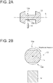
FIG. 2A is a diagram showing a notch formed in a rotational shaft and shows a relative positional relationship between the notch and a displacement sensor. -
FIG. 2B is a diagram showing a notch formed in a rotational shaft and shows the position of the notch formed in the rotational shaft. -
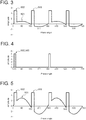
FIG. 3 is a graph showing a rotation waveform of a rotational shaft determined by a rotation waveform determination unit, at time T0. -
FIG. 4 is a graph showing a reference pulse waveform determined by division of a rotation waveform. -
FIG. 5 is a graph showing a rotation waveform of a rotational shaft determined by a rotation waveform determination unit, at time T1. -
FIG. 6A is a graph showing a rotation waveform of a rotational shaft determined by a rotation waveform determination unit, at time T0. -
FIG. 6B is a graph showing a rotation waveform of a rotational shaft determined by a rotation waveform determination unit, at time T2. -
FIG. 6C is a graph showing a rotation waveform of a rotational shaft determined by a rotation waveform determination unit, at time T3. -
FIG. 7 is a flowchart of a contact vibration detection method performed by a contact vibration detection device according to an embodiment of the present invention. -
FIG. 8 is a flowchart of a contact vibration detection method according to another embodiment of the present invention. -
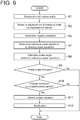
FIG. 9 is a flowchart of a contact vibration detection method according to still another embodiment of the present invention. - Embodiments of the present invention will now be described in detail with reference to the accompanying drawings. However, the following embodiments and the drawings are illustrative only, and various modifications may be applied as long as they do not depart from the object of the present invention. Further, two or more embodiments may be optionally combined in any manner. Further, in the following embodiments, similar elements will be indicated by the same reference numerals, and redundant descriptions thereof will be omitted for convenience.
- It is intended, however, that unless particularly specified, dimensions, materials, shapes, relative positions and the like of components described in the embodiments shall be interpreted as illustrative only and not intended to limit the scope of the present invention.
- For instance, an expression of relative or absolute arrangement such as "in a direction", "along a direction", "parallel", "orthogonal", "centered", "concentric" and "coaxial" shall not be construed as indicating only the arrangement in a strict literal sense, but also includes a state where the arrangement is relatively displaced by a tolerance, or by an angle or a distance whereby it is possible to achieve the same function.
- For instance, an expression of an equal state such as "same" "equal" and "uniform" shall not be construed as indicating only the state in which the feature is strictly equal, but also includes a state in which there is a tolerance or a difference that can still achieve the same function.
- Further, for instance, an expression of a shape such as a rectangular shape or a cylindrical shape shall not be construed as only the geometrically strict shape, but also includes a shape with unevenness or chamfered corners within the range in which the same effect can be achieved.
- On the other hand, an expression such as "comprise", "include", "have", "contain" and "constitute" are not intended to be exclusive of other components.
-
FIG. 1 is a block diagram of arotary machine 200 to which a contactvibration detection device 100 is applied according to an embodiment of the present invention. Therotary machine 200 includes arotary machine body 10 and a contactvibration detection device 100. Among them, therotary machine body 10 is composed of a turbo machine, a turbine, a compressor, or the like, although not depicted. The contactvibration detection device 100 is used to detect contact vibration caused by contact of arotational shaft 12 with astationary part 13 in therotary machine body 10. - The
rotary machine body 10 includes acasing 11, arotational shaft 12, astationary part 13, and adisplacement sensor 14. Thecasing 11 accommodates therotational shaft 12, thestationary part 13, and thedisplacement sensor 14. In a case where therotary machine body 10 is a turbo machine, therotational shaft 12 is rotated by energy of exhaust gas or the like of a ship, for instance. Thestationary part 13 is a seal part and an oil thrower part, for instance, although they are not depicted. - Further, the
displacement sensor 14 is configured to measure displacement of therotational shaft 12 during rotation of therotational shaft 12. Thedisplacement sensor 14 is generally provided to therotary machine body 10. Thedisplacement sensor 14 may include an eddy-current sensor, for instance. Displacement measured by thedisplacement sensor 14 is input to a rotationwaveform determination unit 101 described later. In an embodiment of the present invention, only onedisplacement sensor 14 is provided. - Among them, the
rotational shaft 12 has anotch 12a (pulse waveform generation part) for superimposing a pulse waveform on a rotation waveform generated as therotational shaft 12 rotates. This point will be described with reference toFIGs. 2A and 2B . -
FIGs. 2A and 2B are a diagram showing thenotch 12a formed in therotational shaft 12.FIG. 2A shows a relative positional relationship between thenotch 12a and thedisplacement sensor 14, andFIG. 2B shows the position of thenotch 12a formed in the rotational shaft.FIGs. 2 also show thedisplacement sensor 14. - The
rotational shaft 12 shown inFIG. 2A rotates around a rotational center line L. Further, thenotch 12a, for instance of rectangular cross-section, is formed in the surface of therotational shaft 12. As shown inFIG. 2B , thenotch 12a is formed in the outer peripheral surface of therotational shaft 12 at equal intervals in the circumferential direction of therotational shaft 12. The twonotches 12a have the same size and the same shape. By forming two (or three or more)notches 12a at equal intervals, thenotches 12a can be easily formed in therotational shaft 12. Further, the equidistant notches improve balance during rotation of therotational shaft 12 and allows therotational shaft 12 to stably rotate. - By forming the
notch 12a, a pulse waveform is superimposed on a rotation waveform determined by rotation of therotational shaft 12, which will be described later in more detail. - Referring to
FIG. 1 again, the contactvibration detection device 100 includes a rotationwaveform determination unit 101, a parameterchange detection unit 102, a contactvibration determination unit 103, and anotification unit 104. Among them, the parameterchange detection unit 102 includes an effectivevalue calculation unit 102a, a phaseangle calculation unit 102b, adividing unit 102c, adetection unit 102d, and aparameter database 102e. - The rotation
waveform determination unit 101 determines a rotation waveform of therotational shaft 12 based on displacement of therotational shaft 12 during rotation. An illustrative example of the shape of the rotation waveform is shown inFIG. 3 . -
FIG. 3 is a graph showing arotation waveform 501 of therotational shaft 12 determined by the rotationwaveform determination unit 101 at time T0. Displacement of therotational shaft 12 is measured in real time by thedisplacement sensor 14, and the measured displacement is sent to the rotationwaveform determination unit 101 in real time. Accordingly, the shape of therotation waveform 501, for instance as shown inFIG. 3 , is also determined in real time. - The rotation waveform shown in
FIG. 3 includes a rotation waveform 501 (maximum amplitude = 1) normally generated with rotation of therotational shaft 12 and two pulse waveforms 502 (maximum amplitude = 5) in a range where 0° ≤ phase angle ≤ 360°. Thesepulse waveforms 502 are attributable to the twonotches 12a described with references toFIGs. 2A and 2B . More specifically, when therotational shaft 12 rotates, displacement of therotational shaft 12 largely changes at thenotches 12a formed at equal intervals in the outer peripheral surface of therotational shaft 12. Thus, thepulse waveforms 502 corresponding to the twonotches 12a are superimposed on thenormal rotation waveform 501 with a phase angle difference of 180°. - The
pulse waveform 502 serves as a reference signal of the phase angle in therotation waveform 501, as described later in more detail. That is, the position of the superimposedpulse waveform 502 is unchanged regardless of the change in phase angle of therotation waveform 501 due to therotational shaft 12 acting on thestationary part 13. Accordingly, by calculating the phase angle change of therotation waveform 501 relative to thepulse waveform 502, which is the reference signal, it is possible to detect the phase angle change of therotation waveform 501. - Referring to
FIG. 1 again, the parameterchange detection unit 102 detects the change in parameter, namely, the effective value of the rotation waveform and the phase angle of the rotation waveform. However, the parameter may be one of them. The parameterchange detection unit 102 includes an effectivevalue calculation unit 102a, a phaseangle calculation unit 102b, adividing unit 102c, adetection unit 102d, and aparameter database 102e, as described above. - The effective
value calculation unit 102a calculates the effective value of the rotation waveform. The rotation waveform here means therotation waveform 501 described with reference toFIG. 3 , for instance. The effective value is preferably calculated based on the rotation waveform obtained when therotational shaft 12 rotates in a settling state (i.e., when therotational shaft 12 rotates at a constant rotational speed). - The effective value E of the rotation waveform can be calculated by the following expression (1). Since the size of the pulse waveform is constant, the size (area) of the pulse waveform is not considered in calculating the effective value E for simplicity of calculation.
(Expression 1)
- In the expression (1), x(t) represents a function of the rotation waveform including time t as a variable, and T is a period of the rotation waveform. The calculated effective value E is recorded in the
parameter database 102e. - The phase
angle calculation unit 102b calculates the phase angle of the rotation waveform. The phase angle here means a phase angle relative to the pulse waveform superimposed on the rotation waveform, i.e., a phase angle difference from the pulse waveform. The rotation waveform here means therotation waveform 501 described with reference toFIG. 3 , for instance, and the pulse waveform means thepulse waveform 502 described with reference toFIG. 3 . The phase angle is preferably calculated based on the rotation waveform and the pulse waveform obtained when therotational shaft 12 rotates in a settling state (i.e., when therotational shaft 12 rotates at a constant rotational speed). - The position of the pulse waveform superimposed on the rotation waveform is unchanged regardless of the change in phase angle of the rotation waveform due to contact with the
stationary part 13. Accordingly, by calculating the phase angle change of the rotation waveform relative to the pulse waveform, which is the reference signal, it is possible to precisely detect the change in phase angle (parameter). - The phase angle of the rotation waveform can be calculated by rotational order ratio analysis and fast Fourier transform. More specifically, the phase angle of a complex function F(t) can be calculated by the following expression (2).
(Expression 2)
- In the expression (2), the time array f(x) is composed an array of N data elements to be subjected to Fourier transform. The above expression gives frequency t of 0 to N-1th data elements, and the phase angle of the complex function F(t) is determined by the real and imaginary parts of the complex number (e). The calculated phase angle is recorded in the
parameter database 102e. - As described above, in an embodiment of the present invention, the phase angle of the rotation waveform relative to the pulse waveform as the reference signal is calculated. However, for simplicity of calculation, it is preferable to divide two pulse waveforms and calculate the phase angle of the rotation waveform relative to one reference pulse waveform obtained by the division. In the following, the division of the rotation waveform and the reference pulse waveform will be described in conjunction with the dividing
unit 102c for dividing the rotation waveform. - The dividing
unit 102c determines the reference pulse waveform by dividing the pulse waveform detected in the rotation waveform. The pulse waveform to be divided is the twopulse waveforms 502 described with reference toFIG. 3 , for instance. By division, one reference pulse waveform is determined from the two pulse waveforms corresponding to the twonotches 12a. The reference pulse waveform will now be described with reference toFIG. 3 and FIG. 4 . -
FIG. 4 is a graph showing a reference pulse waveform 503 determined by division of the rotation waveform.FIG. 4 shows one reference pulse waveform 503 (maximum amplitude = 5) in a range where 0° ≤ phase angle ≤ 360°. The amplitude of the reference pulse waveform 503 is the same as the amplitude of the pulse waveform 502 (seeFIG. 3 ). - As described above, in
FIG. 3 , twopulse waveforms 502 exist in a range where 0° ≤ phase angle ≤ 360°. Thus, the dividingunit 102c divides the twopulse waveforms 502 and coverts the twopulse waveforms 502 to onepulse waveform 502. Then, thepulse waveform 502 obtained by conversion is determined as the reference pulse waveform 503. In the example shown inFIG. 4 , since the phase angle of the reference pulse waveform 503 is 20°, the phase angle of the rotation waveform 501 (seeFIG. 3 ) relative to the reference pulse waveform 503 indicates the degree of deviation from 20°. - By determining the reference pulse waveform 503 through division, it is possible to determine one reference pulse waveform from the two or more pulse waveforms corresponding to the
notches 12a. Accordingly, it is possible to easily calculate the phase angle of the rotation waveform 501 (seeFIG. 3 ) relative to the reference pulse waveform 503. - Referring to
FIG. 1 again, thedetection unit 102d detects the change in effective value calculated by the effectivevalue calculation unit 102a and the change in phase angle calculated by the phaseangle calculation unit 102b. More specifically, thedetection unit 102d compares current effective value and phase angle with, for instance, effective value and phase angle recorded in the parameter database one minute before, respectively. Further, thedetection unit 102d determines whether the effective value and the phase angle are changed. This point will be described with reference toFIGs. 3 and 5 . -
FIG. 5 is a graph showing therotation waveform 501 of therotational shaft 12 determined by the rotationwaveform determination unit 101 at time T1. The time T1 here means, for instance, a time one minute after time T0 of therotation waveform 501 shown inFIG. 3 while the phase angle of thenormal rotation waveform 501 is the same. InFIGs. 3 and 5 , the phase angle and the amplitude of thepulse waveform 502 are the same. However, the maximum amplitude (maximum amplitude = 3) of therotation waveform 501 is larger than the amplitude (maximum amplitude = 1) shown inFIG. 3 . Accordingly, although a specific value is not described for simplicity, the effective value calculated from the amplitude is changed between time T0 of the rotation waveform shown inFIG. 3 and time T1 of the rotation waveform shown inFIG. 5 . Thus, in this case, thedetection unit 102d detects the change in effective value. -
FIGs. 6A to 6C are a graph showing therotation waveform 501 of therotational shaft 12 determined by the rotationwaveform determination unit 101.FIG. 6A shows therotation waveform 501 of therotational shaft 12 at time T0,FIG. 6B shows therotation waveform 501 of therotational shaft 12 at time T2, andFIG. 6C shows therotation waveform 501 of therotational shaft 12 at time T3. Among these graphs, therotation waveform 501 shown inFIG. 6A is the same as therotation waveform 501 shown inFIG. 3 except that the scale of the vertical axis is different. Further, time T2 is, for instance, a time two minutes after T0, and time T3 is, for instance, a time three minutes after T0. - In
FIGs. 6A to 6C , the phase angle and the amplitude of thepulse waveform 502 are the same. However, the position of the antinode of therotation waveform 501 changes betweenFIGs. 6A to 6C . More specifically, inFIG. 6A which shows therotation waveform 501 at time T0, the smallest phase angle of the antinode included in therotation waveform 501 is 90°. Accordingly, the phase angle (phase angle difference) relative to the reference pulse waveform 503 (seeFIG. 4 ,phase angle 20°) not shown inFIGs. 6A to 6C is 70°. InFIG. 6B which shows therotation waveform 501 at time T2, the smallest phase angle of the antinode is 67.5°. Accordingly, the phase angle relative to the reference pulse waveform 503 is 47.5°. InFIG. 6C which shows therotation waveform 501 at time T3, the smallest phase angle of the antinode is 45°. Accordingly, the phase angle relative to the reference pulse waveform 503 is 25°. - As above, the phase angle of the
rotation waveform 501 relative to the reference pulse waveform 503 changes between times T0, T2, T3. Thus, in this case, thedetection unit 102d detects the change in phase angle. - Referring to
FIG. 1 again, theparameter database 102e stores the effective value calculated by the effectivevalue calculation unit 102a and the phase angle calculated by the phaseangle calculation unit 102b. As described above, since the effective value and the phase angle are calculated every one minute, for instance, the data are also recorded in theparameter database 102e everyone minute. - The contact
vibration determination unit 103 determines whether the contact vibration occurs based on the presence or absence of the change in effective value and phase angle (parameter) detected by thedetection unit 102d. More specifically, in an embodiment of the present invention, the contactvibration determination unit 103 determines that contact vibration occurs in therotational shaft 12 when the effective value changes and the phase angle also changes. However, as described later in more detail, it may be determined that contact vibration occurs in therotational shaft 12 when one of the effective value or the phase angle changes. - Generally, when the rotational speed is stabilized, and the
rotational shaft 12 is stable, neither the effective value nor the phase angle changes. However, as for the effective value, contact vibration occurs when therotational shaft 12 comes into contact with thestationary part 13 due to some cause. At the contact portion, heat is generated by friction, and the temperature rises. As a result, therotational shaft 12 is bent, and therotational shaft 12 becomes unstable, which increases contact vibration. By repeating this, the rotation waveform is changed due to instability of therotational shaft 12. As a result, the effective value calculated from the rotation waveform changes (increases, for instance). Thus, the contactvibration determination unit 103 determines whether the contact vibration occurs based on the presence or absence of the change in effective value. - As for the phase angle, even if the
rotational shaft 12 becomes unstable due to contact with thestationary part 13, there is a possibility that the change in effective value (i.e., change in amplitude) is extremely reduced by contact that cancels the instability. In this case, the effective value hardly changes. However, since the one contact portion on the circumference of therotational shaft 12 is locally heated by contact between therotational shaft 12 and thestationary part 13, therotational shaft 12 is thermally bent. As a result, therotational shaft 12 that is sufficiently balanced becomes unbalanced due to thermal bend, which causes vibration. Further, since the unbalance due to contact is shifted on the circumference over time, the phase angle of the rotation waveform is shifted. Thus, the contactvibration determination unit 103 determines whether the contact vibration occurs based on the presence or absence of the change in phase angle. - Thus, in an embodiment of the present invention, the contact
vibration determination unit 103 is configured to determine that contact vibration occurs when the change in effective value and the change in phase angle are detected. Consequently, it is possible to improve the detection precision of contact vibration. - Further, in an embodiment of the present invention, the contact
vibration determination unit 103 is configured to determine that contact vibration occurs when the changes in effective value and phase angle (parameter) continue for a predetermined period. In a case where the effective value and the phase angle are calculated at a predetermined time interval (e.g., every one time) as described above, the predetermined period includes that the change occurs 100 times continuously, for instance. Further, for instance, in a case where the effective value and the phase angle are calculated in real time while the rotation waveform is determined, the predetermined period includes that the change occurs for 1 hour 40 minutes continuously. - Thus, it is possible to suppress the erroneous determination that the contact vibration occurs when the parameter (effective value and phase angle) is changed for some reason although the contact vibration does not actually occur. Accordingly, it is possible to improve the detection precision.
- The
notification unit 104 notifies the user of the occurrence of contact vibration when contact vibration is detected by the contactvibration determination unit 103. Thenotification unit 104 enables notification to the user about detection of contact vibration and thus prompts user's appropriate action, for instance, prompts the user to stop the operation of therotary machine 200. Thenotification unit 104 notifies the user by turning on a lamp (not shown) or displaying a notification on a monitor screen (not shown), for instance. - With the contact
vibration detection device 100 having the above configuration, the rotation waveform is determined based on displacement measured by thedisplacement sensor 14, for instance, and contact vibration due to contact of therotational shaft 12 with thestationary part 13 is detected based on the change in parameter (effective value and phase angle) of the determined rotation waveform. Thus, it is possible to detect contact vibration of the rotary machine 200 (more specifically, rotary machine body 10) regardless of a vibration detector. An embodiment of the present invention does not exclude the provision of a vibration detector. - In particular, the
rotary machine 200 including therotational shaft 12 and the contactvibration detection device 100 for instance as shown inFIG. 1 enables detection of contact vibration caused in therotary machine 200 and performs appropriate maintenance of therotary machine 200. - The contact
vibration detection device 100 includes a central processing unit (CPU), a random access memory (RAM), a read only memory (ROM), a hard disk drive (HDD), an interface (I/F), a control circuit, not depicted, and is realized by executing a predetermined control program stored in the ROM by the CPU. -
FIG. 7 is a flowchart of a contact vibration detection method performed by the contactvibration detection device 100 according to an embodiment of the present invention. The contact vibration detection method shown inFIG. 7 detects contact vibration caused by contact of therotational shaft 12 with thestationary part 13. The contact vibration detection method can be performed by the contactvibration detection device 100 shown inFIG. 1 , for instance. In the following, explanation will be given with reference toFIG. 7 , in conjunction withFIG. 1 . - After the
rotational shaft 12 starts rotating, the rotational speed of therotational shaft 12 becomes constant, and therotational shaft 12 rotates stably (step S1). Further, thedisplacement sensor 14 measures displacement of therotational shaft 12 from the start of the rotation of the rotational shaft 12 (step S2). The displacement is measured in real time while therotational shaft 12 rotates stably. Further, the rotationwaveform determination unit 101 determines the rotation waveform of therotational shaft 12 based on displacement of therotational shaft 12 during rotation (step S3, rotation waveform determination step). In this step, in a case where the determination is based on displacement at time T0 for instance, therotation waveform 501 and thepulse waveform 502 shown inFIG. 3 are determined. - Then, the effective
value calculation unit 102a calculates the effective value of the determined rotation waveform (step S4). As a specific calculation method, the method described above for the contactvibration detection device 100 can be used. The calculated effective value is recorded in theparameter database 102e. Further, thedetection unit 102d compares the effective values recorded in theparameter database 102e and determines whether the effective value of the rotation waveform changes (step S5, parameter change detection step). The change in effective value described here is the change described with reference toFIGs. 3 and 5 , for instance. - As a result of determination, if it is determined that the effective value of the rotation waveform changes (Yes in step S5), the contact
vibration determination unit 103 determines whether the change continues for a predetermined period (step S6). The predetermined period continuation described here is the same as the predetermined period continuation described above for the contactvibration detection device 100. If the change in effective value continues for a predetermined period (Yes in step S6), the dividingunit 102c divides the pulse waveform superimposed on therotation waveform 501 whose effective value has been calculated, and determines the reference pulse waveform (step S7). The reference pulse waveform here means the reference pulse waveform 503 described above with reference toFIG. 4 . - If it is determined that the effective value does not change in step S5 (No in step S5), or if it is determined that the change does not continue for a predetermined period in step S6 (No in step S6), the procedure ends. In this case, the effective value recorded in the
parameter database 102e is deleted. - After the reference pulse waveform is determined in step S7, the phase
angle calculation unit 102b calculates the phase angle relative to the reference pulse waveform for the rotation waveform with the determined reference pulse waveform (step S8). As a specific calculation method, the method described above for the contactvibration detection device 100 can be used. The calculated phase angle is recorded in theparameter database 102e. - Further, the
detection unit 102d compares the phase angles recorded in theparameter database 102e and determines whether the phase angle relative to the reference pulse waveform changes (step S9, parameter change detection step). The change in phase angle described here is the change described with reference toFIGs. 6A to 6C , for instance. - As a result of determination, if the
detection unit 102d determines that the phase angle changes (Yes in step S9), the contactvibration determination unit 103 determines whether the change continues for a predetermined period (step S10). The predetermined period continuation described here is the same as the predetermined period continuation described above for the contactvibration detection device 100. If the change continues for a predetermined period (Yes in step S10), the contactvibration determination unit 103 determines that contact vibration due to contact between therotational shaft 12 and thestationary part 13 is present, and the contactvibration determination unit 103 detects contact vibration (step S11, contact vibration determination step). - If it is determined that the phase angle does not change in step S9 (No in step S9), or if it is determined that the change does not continue for a predetermined period in step S10 (No in step S10), the procedure ends. In this case, the effective value and the phase angle recorded in the
parameter database 102e are deleted. - After the contact
vibration determination unit 103 detects contact vibration, thenotification unit 104 notifies the user of detection of contact vibration by turning on a lamp or displaying a notification on a screen, for instance (step S12). Then, the procedure ends. - With the contact vibration detection method described above, the rotation waveform is determined based on displacement measured by the
displacement sensor 14, for instance, and contact vibration due to contact of therotational shaft 12 with thestationary part 13 is detected based on the change in parameter (effective value and phase angle) of the determined rotation waveform. Thus, it is possible to detect contact vibration of the rotary machine 200 (more specifically, rotary machine body 10) regardless of a vibration detector. -
FIG. 8 is a flowchart of a contact vibration detection method according to another embodiment of the present invention. Redundant descriptions for the same steps as shown inFIG. 7 will be omitted for simplicity of description. - The procedure shown in
FIG. 8 is applied to detect contact vibration based on only the change in effective value in the procedure shown inFIG. 7 . More specifically, if the change in effective value continues for a predetermined period (Yes in step S6), the contactvibration determination unit 103 determines that contact vibration due to contact between therotational shaft 12 and thestationary part 13 is present, and the contactvibration determination unit 103 detects contact vibration (step S11, contact vibration determination step). Then, the user is notified (step S12), and the procedure ends, like the procedure shown inFIG. 7 . - As described above, even if the
rotational shaft 12 becomes unstable due to contact with thestationary part 13, there is a possibility that the change in effective value is extremely reduced by another contact that cancels the instability. However, another contact that completely cancels the instability of therotational shaft 12 is not very likely to occur. Therefore, if therotational shaft 12 comes into contact with thestationary part 13, it is usually considered that the effective value of the rotational waveform changes. Since this change in effective value can be calculated by a simple calculation expression, for instance as shown in the expression (1), the change in effective value can be easily detected. Accordingly, with the procedure shown inFIG. 8 for detecting contact vibration only by the effective value, it is possible to simply and easily detect contact vibration. -
FIG. 9 is a flowchart of a contact vibration detection method according to still another embodiment of the present invention. Redundant descriptions for the same steps as shown inFIG. 7 will be omitted for simplicity of description. - The procedure shown in
FIG. 9 is applied to detect contact vibration based on only the change in phase angle in the procedure shown inFIG. 7 . More specifically, after the rotationwaveform determination unit 101 determines the rotation waveform (step S3), the dividingunit 102c divides the pulse waveform and determines the reference pulse waveform (step S7). Then, like the procedure shown inFIG. 7 , contact vibration is detected by the phase angle (steps S7 to S11), the user is notified (step S12), and the procedure ends. - As described above, if the
rotational shaft 12 comes into contact with thestationary part 13, contact vibration occurs. Along with this, the contact portion is heated, and the temperature of the contact portion rises. As a result, therotational shaft 12 is bent, and therotational shaft 12 becomes unstable. Thus, by determining the presence or absence of contact vibration based on only the phase angle, it is possible to detect contact vibration. -
- 10
- Rotary machine body
- 11
- Casing
- 12
- Rotational shaft
- 12a
- Notch
- 13
- Stationary part
- 14
- Displacement sensor
- 100
- Contact vibration detection device
- 101
- Rotation waveform determination unit
- 102
- Parameter change detection unit
- 102a
- Effective value calculation unit
- 102b
- Phase angle calculation unit
- 102c
- Dividing unit
- 102d
- Detection unit
- 102e
- Parameter database
- 103
- Contact vibration determination unit
- 104
- Notification unit
- 200
- Rotary machine
- 501
- Rotation waveform
- 502
- Pulse waveform
- 503
- Reference pulse waveform
Claims (9)
- A contact vibration detection device for detecting contact vibration due to contact between a rotational shaft and a stationary part, the contact vibration detection device comprising:a rotation waveform determination unit configured to determine a rotation waveform of the rotational shaft based on displacement of the rotational shaft during rotation;a parameter change detection unit configured to detect a change in a parameter of at least one of an effective value of the rotation waveform or a phase angle of the rotation waveform; anda contact vibration determination unit configured to determine whether the contact vibration occurs based on presence or absence of the change in the parameter.
- The contact vibration detection device according to claim 1,
wherein the contact vibration determination unit is configured to determine that the contact vibration occurs if the change in the parameter continues for a predetermined period. - The contact vibration detection device according to claim 1 or 2,
wherein the rotational shaft has a pulse waveform generation part for superimposing a pulse waveform as a reference of the phase angle on the rotation waveform, and
wherein the parameter change detection unit is configured to detect a change in the phase angle relative to the pulse waveform and thereby detect the change in the parameter. - The contact vibration detection device according to claim 3,
wherein the pulse waveform generation part includes two or more notches formed in an outer peripheral surface of the rotational shaft at equal intervals in a circumferential direction of the rotational shaft. - The contact vibration detection device according to claim 3 or 4,
wherein the parameter change detection unit is configured to divide the detected pulse waveform to determine a reference pulse waveform, and
wherein the parameter change detection unit is configured to detect a change in the phase angle relative to the reference pulse waveform and thereby detect the change in the parameter. - The contact vibration detection device according to any one of claims 1 to 5,
wherein the parameter change detection unit is configured to detect a change in the effective value and a change in the phase angle, and
wherein the contact vibration determination unit is configured to determine that the contact vibration occurs if the change in the effective value and the change in the phase angle are detected. - The contact vibration detection device according to any one of claims 1 to 6, further comprising a notification unit configured to notify a user of occurrence of the contact vibration if the contact vibration is detected.
- A rotary machine comprising:a rotational shaft; anda contact vibration detection device according to anyone of claims 1 to 7.
- A contact vibration detection method for detecting contact vibration due to contact between a rotational shaft and a stationary part, the contact vibration detection method comprising:a rotation waveform determination step of determining a rotation waveform of the rotational shaft based on displacement of the rotational shaft during rotation;a parameter change detection step of detecting a change in a parameter of at least one of an effective value of the rotation waveform or a phase angle of the rotation waveform; anda contact vibration determination step of determining whether the contact vibration occurs based on the change in the parameter.
Applications Claiming Priority (2)
| Application Number | Priority Date | Filing Date | Title |
|---|---|---|---|
| JP2018063632A JP6559824B1 (en) | 2018-03-29 | 2018-03-29 | Contact vibration detection device, rotating machine including the same, and contact vibration detection method |
| PCT/JP2019/001239 WO2019187517A1 (en) | 2018-03-29 | 2019-01-17 | Contact vibration detection device, rotating machine provided with same, and contact vibration detection method |
Publications (3)
| Publication Number | Publication Date |
|---|---|
| EP3605052A1 true EP3605052A1 (en) | 2020-02-05 |
| EP3605052A4 EP3605052A4 (en) | 2020-06-17 |
| EP3605052B1 EP3605052B1 (en) | 2022-02-23 |
Family
ID=67614876
Family Applications (1)
| Application Number | Title | Priority Date | Filing Date |
|---|---|---|---|
| EP19775623.2A Active EP3605052B1 (en) | 2018-03-29 | 2019-01-17 | Contact vibration detection device, rotating machine provided with same, and contact vibration detection method |
Country Status (6)
| Country | Link |
|---|---|
| US (1) | US11525753B2 (en) |
| EP (1) | EP3605052B1 (en) |
| JP (1) | JP6559824B1 (en) |
| KR (1) | KR102257410B1 (en) |
| CN (1) | CN110546477B (en) |
| WO (1) | WO2019187517A1 (en) |
Families Citing this family (1)
| Publication number | Priority date | Publication date | Assignee | Title |
|---|---|---|---|---|
| WO2023027003A1 (en) | 2021-08-25 | 2023-03-02 | イーグル工業株式会社 | Sliding component |
Family Cites Families (19)
| Publication number | Priority date | Publication date | Assignee | Title |
|---|---|---|---|---|
| JPS54106401U (en) * | 1978-01-13 | 1979-07-26 | ||
| JPS5847736U (en) | 1981-09-28 | 1983-03-31 | 株式会社明電舎 | Shaft vibration monitoring device for rotating electrical machines |
| JPS5847735U (en) | 1981-09-28 | 1983-03-31 | 株式会社明電舎 | Shaft vibration monitoring device for rotating electrical machines |
| JPS6112027U (en) * | 1984-06-27 | 1986-01-24 | 株式会社日立製作所 | Vibration monitoring device for rotating machines |
| JPS6243538A (en) * | 1985-08-20 | 1987-02-25 | Toshiba Corp | Abnormality monitor for rotating part of rotary machine |
| JPH02232529A (en) * | 1989-03-07 | 1990-09-14 | Toshiba Corp | Method and apparatus for diagnosing vibration of rotary machine |
| US5144840A (en) * | 1989-06-23 | 1992-09-08 | General Electric Company | Vibration detector and method for rotating shaft |
| US5198763A (en) | 1990-02-20 | 1993-03-30 | Nikkiso Co., Ltd. | Apparatus for monitoring the axial and radial wear on a bearing of a rotary shaft |
| JP3286073B2 (en) * | 1994-03-15 | 2002-05-27 | 株式会社東芝 | Shaft Vibration Monitoring System for Recirculation Pump Built in Reactor |
| JPH11160482A (en) * | 1997-11-25 | 1999-06-18 | Hitachi Ltd | Rotation direction monitoring device of recirculation pump built in reactor |
| JP4533560B2 (en) | 2001-06-14 | 2010-09-01 | 三菱重工業株式会社 | Vibration diagnosis system for rotating machinery |
| JP2004019841A (en) | 2002-06-19 | 2004-01-22 | Mitsubishi Heavy Ind Ltd | Alignment monitoring device and alignment adjusting device |
| JP2008082879A (en) * | 2006-09-27 | 2008-04-10 | Toshiba Corp | Torsional vibration measuring apparatus and method |
| JP2008170275A (en) * | 2007-01-11 | 2008-07-24 | Toshiba Corp | Wireless vibration measurement system and method |
| CN102449445B (en) * | 2009-05-05 | 2014-12-17 | S.P.M.仪器公司 | An apparatus and a method for analysing the vibration of a machine having a rotating part |
| JP5742312B2 (en) * | 2011-03-10 | 2015-07-01 | 株式会社ジェイテクト | Chatter vibration detection method |
| JP6239491B2 (en) * | 2014-12-09 | 2017-11-29 | 三菱重工業株式会社 | Rotating machine state monitoring device, rotating machine, and rotating machine state monitoring method |
| US20160377510A1 (en) * | 2015-06-24 | 2016-12-29 | Aktiebolaget Skf | Synchronized measurements for a portable multi-channel wireless sensor system |
| US10228305B2 (en) * | 2016-01-18 | 2019-03-12 | Pratt & Whitney Canada Corp. | Shaft shear detection through shaft oscillation |
-
2018
- 2018-03-29 JP JP2018063632A patent/JP6559824B1/en active Active
-
2019
- 2019-01-17 US US16/609,293 patent/US11525753B2/en active Active
- 2019-01-17 EP EP19775623.2A patent/EP3605052B1/en active Active
- 2019-01-17 WO PCT/JP2019/001239 patent/WO2019187517A1/en not_active Ceased
- 2019-01-17 CN CN201980001786.XA patent/CN110546477B/en active Active
- 2019-01-17 KR KR1020197028334A patent/KR102257410B1/en active Active
Also Published As
| Publication number | Publication date |
|---|---|
| JP6559824B1 (en) | 2019-08-14 |
| KR102257410B1 (en) | 2021-05-27 |
| WO2019187517A1 (en) | 2019-10-03 |
| KR20190123763A (en) | 2019-11-01 |
| CN110546477A (en) | 2019-12-06 |
| CN110546477B (en) | 2021-12-14 |
| EP3605052A4 (en) | 2020-06-17 |
| EP3605052B1 (en) | 2022-02-23 |
| US20200056956A1 (en) | 2020-02-20 |
| US11525753B2 (en) | 2022-12-13 |
| JP2019174317A (en) | 2019-10-10 |
Similar Documents
| Publication | Publication Date | Title |
|---|---|---|
| RU2465562C2 (en) | Device and method of contactless blade vibration measurement | |
| CN101622516B (en) | Blade shroud vibration monitor | |
| KR0139213B1 (en) | Shrouded turbine blade vibration monitor | |
| EP2578811B1 (en) | Method for determining position of rotating blades having variable thickness. | |
| US12253407B2 (en) | Vibration detection through correlation of nodal measurements of a physical quantity | |
| US10156440B2 (en) | Blade tip timing | |
| EP2073022A1 (en) | Method and apparatus for monitoring the rotational speed of a gas turbine shaft | |
| GB2455797A (en) | Monitoring the rotational speed of a turbine shaft | |
| US11686649B2 (en) | Early sign detection device and early sign detection method | |
| US11525753B2 (en) | Contact vibration detection device, rotary machine including the same, and contact vibration detection method | |
| JP2000321122A (en) | Vibration measuring apparatus for rotor blade | |
| JP2019100210A (en) | Rotor blade monitoring system, rotor blade monitoring device, rotor blade monitoring method, program | |
| US20210239730A1 (en) | Reverse detection for rotating machinery | |
| JP3129406B2 (en) | Wing vibration measurement device | |
| CN115210454A (en) | Adaptive voltage threshold for turbine engines | |
| US12060800B2 (en) | System and method for determining rotor whirl displacement | |
| JP6455702B2 (en) | Method and apparatus for measuring vibration of rotating body | |
| JPH07253375A (en) | Eccentricity detection method and device | |
| JP2022066735A (en) | Turbine rotor bend detection device and turbine rotor bend detection method | |
| US20160319695A1 (en) | System and methods for determining blade clearance for asymmertic rotors | |
| JP6587406B2 (en) | Compressor inspection device | |
| JPH03210413A (en) | Displacement detector | |
| JP2015017982A (en) | Component monitoring system for electric machines |
Legal Events
| Date | Code | Title | Description |
|---|---|---|---|
| STAA | Information on the status of an ep patent application or granted ep patent |
Free format text: STATUS: THE INTERNATIONAL PUBLICATION HAS BEEN MADE |
|
| PUAI | Public reference made under article 153(3) epc to a published international application that has entered the european phase |
Free format text: ORIGINAL CODE: 0009012 |
|
| STAA | Information on the status of an ep patent application or granted ep patent |
Free format text: STATUS: REQUEST FOR EXAMINATION WAS MADE |
|
| 17P | Request for examination filed |
Effective date: 20191028 |
|
| AK | Designated contracting states |
Kind code of ref document: A1 Designated state(s): AL AT BE BG CH CY CZ DE DK EE ES FI FR GB GR HR HU IE IS IT LI LT LU LV MC MK MT NL NO PL PT RO RS SE SI SK SM TR |
|
| AX | Request for extension of the european patent |
Extension state: BA ME |
|
| A4 | Supplementary search report drawn up and despatched |
Effective date: 20200520 |
|
| RIC1 | Information provided on ipc code assigned before grant |
Ipc: G01M 13/00 20190101AFI20200514BHEP Ipc: G01H 9/00 20060101ALI20200514BHEP |
|
| STAA | Information on the status of an ep patent application or granted ep patent |
Free format text: STATUS: EXAMINATION IS IN PROGRESS |
|
| 17Q | First examination report despatched |
Effective date: 20210217 |
|
| REG | Reference to a national code |
Ref country code: DE Ref legal event code: R079 Ref document number: 602019011948 Country of ref document: DE Free format text: PREVIOUS MAIN CLASS: G01M0099000000 Ipc: G01H0003000000 |
|
| DAV | Request for validation of the european patent (deleted) | ||
| DAX | Request for extension of the european patent (deleted) | ||
| GRAP | Despatch of communication of intention to grant a patent |
Free format text: ORIGINAL CODE: EPIDOSNIGR1 |
|
| STAA | Information on the status of an ep patent application or granted ep patent |
Free format text: STATUS: GRANT OF PATENT IS INTENDED |
|
| INTG | Intention to grant announced |
Effective date: 20210716 |
|
| RIC1 | Information provided on ipc code assigned before grant |
Ipc: G01H 3/00 20060101AFI20210705BHEP Ipc: G01M 13/00 20190101ALI20210705BHEP Ipc: G01H 9/00 20060101ALI20210705BHEP |
|
| RIN1 | Information on inventor provided before grant (corrected) |
Inventor name: YOSHIDA, TADASHI Inventor name: SASAKI, RYOJI Inventor name: NISHIMURA, HIDETAKA Inventor name: TSUJI, TAKESHI |
|
| GRAS | Grant fee paid |
Free format text: ORIGINAL CODE: EPIDOSNIGR3 |
|
| RAP1 | Party data changed (applicant data changed or rights of an application transferred) |
Owner name: MITSUBISHI HEAVY INDUSTRIES MARINE MACHINERY & EQUIPMENT CO., LTD. |
|
| GRAA | (expected) grant |
Free format text: ORIGINAL CODE: 0009210 |
|
| STAA | Information on the status of an ep patent application or granted ep patent |
Free format text: STATUS: THE PATENT HAS BEEN GRANTED |
|
| AK | Designated contracting states |
Kind code of ref document: B1 Designated state(s): AL AT BE BG CH CY CZ DE DK EE ES FI FR GB GR HR HU IE IS IT LI LT LU LV MC MK MT NL NO PL PT RO RS SE SI SK SM TR |
|
| REG | Reference to a national code |
Ref country code: GB Ref legal event code: FG4D |
|
| REG | Reference to a national code |
Ref country code: CH Ref legal event code: EP |
|
| REG | Reference to a national code |
Ref country code: AT Ref legal event code: REF Ref document number: 1470825 Country of ref document: AT Kind code of ref document: T Effective date: 20220315 |
|
| REG | Reference to a national code |
Ref country code: IE Ref legal event code: FG4D |
|
| REG | Reference to a national code |
Ref country code: DE Ref legal event code: R096 Ref document number: 602019011948 Country of ref document: DE |
|
| REG | Reference to a national code |
Ref country code: LT Ref legal event code: MG9D |
|
| REG | Reference to a national code |
Ref country code: NL Ref legal event code: MP Effective date: 20220223 |
|
| REG | Reference to a national code |
Ref country code: AT Ref legal event code: MK05 Ref document number: 1470825 Country of ref document: AT Kind code of ref document: T Effective date: 20220223 |
|
| PG25 | Lapsed in a contracting state [announced via postgrant information from national office to epo] |
Ref country code: SE Free format text: LAPSE BECAUSE OF FAILURE TO SUBMIT A TRANSLATION OF THE DESCRIPTION OR TO PAY THE FEE WITHIN THE PRESCRIBED TIME-LIMIT Effective date: 20220223 Ref country code: RS Free format text: LAPSE BECAUSE OF FAILURE TO SUBMIT A TRANSLATION OF THE DESCRIPTION OR TO PAY THE FEE WITHIN THE PRESCRIBED TIME-LIMIT Effective date: 20220223 Ref country code: PT Free format text: LAPSE BECAUSE OF FAILURE TO SUBMIT A TRANSLATION OF THE DESCRIPTION OR TO PAY THE FEE WITHIN THE PRESCRIBED TIME-LIMIT Effective date: 20220623 Ref country code: NO Free format text: LAPSE BECAUSE OF FAILURE TO SUBMIT A TRANSLATION OF THE DESCRIPTION OR TO PAY THE FEE WITHIN THE PRESCRIBED TIME-LIMIT Effective date: 20220523 Ref country code: NL Free format text: LAPSE BECAUSE OF FAILURE TO SUBMIT A TRANSLATION OF THE DESCRIPTION OR TO PAY THE FEE WITHIN THE PRESCRIBED TIME-LIMIT Effective date: 20220223 Ref country code: LT Free format text: LAPSE BECAUSE OF FAILURE TO SUBMIT A TRANSLATION OF THE DESCRIPTION OR TO PAY THE FEE WITHIN THE PRESCRIBED TIME-LIMIT Effective date: 20220223 Ref country code: HR Free format text: LAPSE BECAUSE OF FAILURE TO SUBMIT A TRANSLATION OF THE DESCRIPTION OR TO PAY THE FEE WITHIN THE PRESCRIBED TIME-LIMIT Effective date: 20220223 Ref country code: ES Free format text: LAPSE BECAUSE OF FAILURE TO SUBMIT A TRANSLATION OF THE DESCRIPTION OR TO PAY THE FEE WITHIN THE PRESCRIBED TIME-LIMIT Effective date: 20220223 Ref country code: BG Free format text: LAPSE BECAUSE OF FAILURE TO SUBMIT A TRANSLATION OF THE DESCRIPTION OR TO PAY THE FEE WITHIN THE PRESCRIBED TIME-LIMIT Effective date: 20220523 |
|
| PG25 | Lapsed in a contracting state [announced via postgrant information from national office to epo] |
Ref country code: PL Free format text: LAPSE BECAUSE OF FAILURE TO SUBMIT A TRANSLATION OF THE DESCRIPTION OR TO PAY THE FEE WITHIN THE PRESCRIBED TIME-LIMIT Effective date: 20220223 Ref country code: LV Free format text: LAPSE BECAUSE OF FAILURE TO SUBMIT A TRANSLATION OF THE DESCRIPTION OR TO PAY THE FEE WITHIN THE PRESCRIBED TIME-LIMIT Effective date: 20220223 Ref country code: GR Free format text: LAPSE BECAUSE OF FAILURE TO SUBMIT A TRANSLATION OF THE DESCRIPTION OR TO PAY THE FEE WITHIN THE PRESCRIBED TIME-LIMIT Effective date: 20220524 Ref country code: FI Free format text: LAPSE BECAUSE OF FAILURE TO SUBMIT A TRANSLATION OF THE DESCRIPTION OR TO PAY THE FEE WITHIN THE PRESCRIBED TIME-LIMIT Effective date: 20220223 Ref country code: AT Free format text: LAPSE BECAUSE OF FAILURE TO SUBMIT A TRANSLATION OF THE DESCRIPTION OR TO PAY THE FEE WITHIN THE PRESCRIBED TIME-LIMIT Effective date: 20220223 |
|
| PG25 | Lapsed in a contracting state [announced via postgrant information from national office to epo] |
Ref country code: IS Free format text: LAPSE BECAUSE OF FAILURE TO SUBMIT A TRANSLATION OF THE DESCRIPTION OR TO PAY THE FEE WITHIN THE PRESCRIBED TIME-LIMIT Effective date: 20220623 |
|
| PG25 | Lapsed in a contracting state [announced via postgrant information from national office to epo] |
Ref country code: SM Free format text: LAPSE BECAUSE OF FAILURE TO SUBMIT A TRANSLATION OF THE DESCRIPTION OR TO PAY THE FEE WITHIN THE PRESCRIBED TIME-LIMIT Effective date: 20220223 Ref country code: SK Free format text: LAPSE BECAUSE OF FAILURE TO SUBMIT A TRANSLATION OF THE DESCRIPTION OR TO PAY THE FEE WITHIN THE PRESCRIBED TIME-LIMIT Effective date: 20220223 Ref country code: RO Free format text: LAPSE BECAUSE OF FAILURE TO SUBMIT A TRANSLATION OF THE DESCRIPTION OR TO PAY THE FEE WITHIN THE PRESCRIBED TIME-LIMIT Effective date: 20220223 Ref country code: EE Free format text: LAPSE BECAUSE OF FAILURE TO SUBMIT A TRANSLATION OF THE DESCRIPTION OR TO PAY THE FEE WITHIN THE PRESCRIBED TIME-LIMIT Effective date: 20220223 Ref country code: DK Free format text: LAPSE BECAUSE OF FAILURE TO SUBMIT A TRANSLATION OF THE DESCRIPTION OR TO PAY THE FEE WITHIN THE PRESCRIBED TIME-LIMIT Effective date: 20220223 Ref country code: CZ Free format text: LAPSE BECAUSE OF FAILURE TO SUBMIT A TRANSLATION OF THE DESCRIPTION OR TO PAY THE FEE WITHIN THE PRESCRIBED TIME-LIMIT Effective date: 20220223 |
|
| REG | Reference to a national code |
Ref country code: DE Ref legal event code: R097 Ref document number: 602019011948 Country of ref document: DE |
|
| PG25 | Lapsed in a contracting state [announced via postgrant information from national office to epo] |
Ref country code: AL Free format text: LAPSE BECAUSE OF FAILURE TO SUBMIT A TRANSLATION OF THE DESCRIPTION OR TO PAY THE FEE WITHIN THE PRESCRIBED TIME-LIMIT Effective date: 20220223 |
|
| PLBE | No opposition filed within time limit |
Free format text: ORIGINAL CODE: 0009261 |
|
| STAA | Information on the status of an ep patent application or granted ep patent |
Free format text: STATUS: NO OPPOSITION FILED WITHIN TIME LIMIT |
|
| 26N | No opposition filed |
Effective date: 20221124 |
|
| PG25 | Lapsed in a contracting state [announced via postgrant information from national office to epo] |
Ref country code: SI Free format text: LAPSE BECAUSE OF FAILURE TO SUBMIT A TRANSLATION OF THE DESCRIPTION OR TO PAY THE FEE WITHIN THE PRESCRIBED TIME-LIMIT Effective date: 20220223 |
|
| PG25 | Lapsed in a contracting state [announced via postgrant information from national office to epo] |
Ref country code: IT Free format text: LAPSE BECAUSE OF FAILURE TO SUBMIT A TRANSLATION OF THE DESCRIPTION OR TO PAY THE FEE WITHIN THE PRESCRIBED TIME-LIMIT Effective date: 20220223 |
|
| PG25 | Lapsed in a contracting state [announced via postgrant information from national office to epo] |
Ref country code: LU Free format text: LAPSE BECAUSE OF NON-PAYMENT OF DUE FEES Effective date: 20230117 |
|
| REG | Reference to a national code |
Ref country code: BE Ref legal event code: MM Effective date: 20230131 |
|
| PG25 | Lapsed in a contracting state [announced via postgrant information from national office to epo] |
Ref country code: FR Free format text: LAPSE BECAUSE OF NON-PAYMENT OF DUE FEES Effective date: 20230131 Ref country code: BE Free format text: LAPSE BECAUSE OF NON-PAYMENT OF DUE FEES Effective date: 20230131 |
|
| PG25 | Lapsed in a contracting state [announced via postgrant information from national office to epo] |
Ref country code: IE Free format text: LAPSE BECAUSE OF NON-PAYMENT OF DUE FEES Effective date: 20230117 |
|
| PG25 | Lapsed in a contracting state [announced via postgrant information from national office to epo] |
Ref country code: MC Free format text: LAPSE BECAUSE OF FAILURE TO SUBMIT A TRANSLATION OF THE DESCRIPTION OR TO PAY THE FEE WITHIN THE PRESCRIBED TIME-LIMIT Effective date: 20220223 |
|
| PG25 | Lapsed in a contracting state [announced via postgrant information from national office to epo] |
Ref country code: MC Free format text: LAPSE BECAUSE OF FAILURE TO SUBMIT A TRANSLATION OF THE DESCRIPTION OR TO PAY THE FEE WITHIN THE PRESCRIBED TIME-LIMIT Effective date: 20220223 |
|
| PG25 | Lapsed in a contracting state [announced via postgrant information from national office to epo] |
Ref country code: CY Free format text: LAPSE BECAUSE OF FAILURE TO SUBMIT A TRANSLATION OF THE DESCRIPTION OR TO PAY THE FEE WITHIN THE PRESCRIBED TIME-LIMIT; INVALID AB INITIO Effective date: 20190117 |
|
| PG25 | Lapsed in a contracting state [announced via postgrant information from national office to epo] |
Ref country code: HU Free format text: LAPSE BECAUSE OF FAILURE TO SUBMIT A TRANSLATION OF THE DESCRIPTION OR TO PAY THE FEE WITHIN THE PRESCRIBED TIME-LIMIT; INVALID AB INITIO Effective date: 20190117 |
|
| PG25 | Lapsed in a contracting state [announced via postgrant information from national office to epo] |
Ref country code: TR Free format text: LAPSE BECAUSE OF FAILURE TO SUBMIT A TRANSLATION OF THE DESCRIPTION OR TO PAY THE FEE WITHIN THE PRESCRIBED TIME-LIMIT Effective date: 20220223 |
|
| PGFP | Annual fee paid to national office [announced via postgrant information from national office to epo] |
Ref country code: GB Payment date: 20251127 Year of fee payment: 8 |
|
| REG | Reference to a national code |
Ref country code: CH Ref legal event code: U11 Free format text: ST27 STATUS EVENT CODE: U-0-0-U10-U11 (AS PROVIDED BY THE NATIONAL OFFICE) Effective date: 20260201 |
|
| PGFP | Annual fee paid to national office [announced via postgrant information from national office to epo] |
Ref country code: DE Payment date: 20251203 Year of fee payment: 8 |
|
| PGFP | Annual fee paid to national office [announced via postgrant information from national office to epo] |
Ref country code: CH Payment date: 20260201 Year of fee payment: 8 |