EP3604913B1 - An improved lighting device - Google Patents
An improved lighting device Download PDFInfo
- Publication number
- EP3604913B1 EP3604913B1 EP19188671.2A EP19188671A EP3604913B1 EP 3604913 B1 EP3604913 B1 EP 3604913B1 EP 19188671 A EP19188671 A EP 19188671A EP 3604913 B1 EP3604913 B1 EP 3604913B1
- Authority
- EP
- European Patent Office
- Prior art keywords
- section bar
- led strip
- led
- installation
- cavity
- Prior art date
- Legal status (The legal status is an assumption and is not a legal conclusion. Google has not performed a legal analysis and makes no representation as to the accuracy of the status listed.)
- Active
Links
Images

Classifications
-
- F—MECHANICAL ENGINEERING; LIGHTING; HEATING; WEAPONS; BLASTING
- F21—LIGHTING
- F21V—FUNCTIONAL FEATURES OR DETAILS OF LIGHTING DEVICES OR SYSTEMS THEREOF; STRUCTURAL COMBINATIONS OF LIGHTING DEVICES WITH OTHER ARTICLES, NOT OTHERWISE PROVIDED FOR
- F21V15/00—Protecting lighting devices from damage
- F21V15/01—Housings, e.g. material or assembling of housing parts
- F21V15/013—Housings, e.g. material or assembling of housing parts the housing being an extrusion
-
- E—FIXED CONSTRUCTIONS
- E04—BUILDING
- E04F—FINISHING WORK ON BUILDINGS, e.g. STAIRS, FLOORS
- E04F10/00—Sunshades, e.g. Florentine blinds or jalousies; Outside screens; Awnings or baldachins
- E04F10/02—Sunshades, e.g. Florentine blinds or jalousies; Outside screens; Awnings or baldachins of flexible canopy materials, e.g. canvas ; Baldachins
- E04F10/06—Sunshades, e.g. Florentine blinds or jalousies; Outside screens; Awnings or baldachins of flexible canopy materials, e.g. canvas ; Baldachins comprising a roller-blind with means for holding the end away from a building
- E04F10/0611—Sunshades, e.g. Florentine blinds or jalousies; Outside screens; Awnings or baldachins of flexible canopy materials, e.g. canvas ; Baldachins comprising a roller-blind with means for holding the end away from a building with articulated arms supporting the movable end of the blind for deployment of the blind
-
- F—MECHANICAL ENGINEERING; LIGHTING; HEATING; WEAPONS; BLASTING
- F21—LIGHTING
- F21S—NON-PORTABLE LIGHTING DEVICES; SYSTEMS THEREOF; VEHICLE LIGHTING DEVICES SPECIALLY ADAPTED FOR VEHICLE EXTERIORS
- F21S4/00—Lighting devices or systems using a string or strip of light sources
- F21S4/20—Lighting devices or systems using a string or strip of light sources with light sources held by or within elongate supports
- F21S4/28—Lighting devices or systems using a string or strip of light sources with light sources held by or within elongate supports rigid, e.g. LED bars
-
- F—MECHANICAL ENGINEERING; LIGHTING; HEATING; WEAPONS; BLASTING
- F21—LIGHTING
- F21V—FUNCTIONAL FEATURES OR DETAILS OF LIGHTING DEVICES OR SYSTEMS THEREOF; STRUCTURAL COMBINATIONS OF LIGHTING DEVICES WITH OTHER ARTICLES, NOT OTHERWISE PROVIDED FOR
- F21V31/00—Gas-tight or water-tight arrangements
-
- F—MECHANICAL ENGINEERING; LIGHTING; HEATING; WEAPONS; BLASTING
- F21—LIGHTING
- F21V—FUNCTIONAL FEATURES OR DETAILS OF LIGHTING DEVICES OR SYSTEMS THEREOF; STRUCTURAL COMBINATIONS OF LIGHTING DEVICES WITH OTHER ARTICLES, NOT OTHERWISE PROVIDED FOR
- F21V33/00—Structural combinations of lighting devices with other articles, not otherwise provided for
- F21V33/006—General building constructions or finishing work for buildings, e.g. roofs, gutters, stairs or floors; Garden equipment; Sunshades or parasols
-
- E—FIXED CONSTRUCTIONS
- E04—BUILDING
- E04C—STRUCTURAL ELEMENTS; BUILDING MATERIALS
- E04C3/00—Structural elongated elements designed for load-supporting
- E04C3/02—Joists; Girders, trusses, or trusslike structures, e.g. prefabricated; Lintels; Transoms; Braces
- E04C3/29—Joists; Girders, trusses, or trusslike structures, e.g. prefabricated; Lintels; Transoms; Braces built-up from parts of different material, i.e. composite structures
-
- F—MECHANICAL ENGINEERING; LIGHTING; HEATING; WEAPONS; BLASTING
- F21—LIGHTING
- F21Y—INDEXING SCHEME ASSOCIATED WITH SUBCLASSES F21K, F21L, F21S and F21V, RELATING TO THE FORM OR THE KIND OF THE LIGHT SOURCES OR OF THE COLOUR OF THE LIGHT EMITTED
- F21Y2115/00—Light-generating elements of semiconductor light sources
- F21Y2115/10—Light-emitting diodes [LED]
Definitions
- the present invention relates to an improved lighting device for a structure and/or installation in which illumination is required and/or provided, preferably for a roofing installation, in particular for a pergola or curtain, but also for a piece of furniture or a furnishing complement.
- strips of lights preferably strips of LED lights (also called “led strips")
- strips of lights preferably strips of LED lights (also called “led strips")
- the LED strips can be applied to the articulated arms and/or to the rigid beam which is moved and/or to the support structure of the curtain, while in the sliding curtains the LED strips are applied to the guides and/or uprights supporting the guides and/or other parts of the tent support structure.
- extruded section bars of polymeric material inside which the LED diodes are embedded, have already been proposed on the market.
- the extruded sections are then hermetically closed at their ends.
- the extruded section thus obtained which is closed at its ends, is available on the market with predefined dimensions and, therefore, at the time of its installation it is difficult to customize according to the particular characteristics of the roofing installation, such as for example those defined by the length of the component of the cover to which the section bar - with the LED strips inside - must be applied.
- this type of extruded section with the LED diodes inside cannot be tailor cut according to the specific installation requirements since, otherwise, it would then be open at at least one of its ends and, therefore, the LED diodes would be exposed to solid particles and liquids from the external environment.
- US 2012/0182755 presents a solution in which a LED strip is coupled with optics which allow a uniform diffusion of the light produced by the LED diodes of the strip itself, thus avoiding the formation of luminous "spots".
- the LEDs and the optics are wrapped by covering films, which however do not by themselves define a suitable protection from the internal environment. Therefore, the LED strip diodes and the optics, partially wrapped by said covering films, are inserted inside a section bar which has the function of protecting them from dust and atmospheric agents. Furthermore, in order to obtain effective protection of the LEDs from the external environment, the section bar is closed at both ends by a pair of plugs.
- WO 2005/106320 presents a solution in which a LED strip is positioned inside a section bar, which is subsequently closed, and filled with a filling material (for example silicone) to cover and protect the LED diodes.
- a filling material for example silicone
- US 2011/0007514 presents a solution in which a LED strip is inserted inside a section bar, which is subsequently sealed at the ends by plugs to allow insulation of the LED strip to be obtained inside the section bar itself.
- This solution is not completely satisfactory since the plugs are particularly complicated to manufacture, thus making this solution particularly expensive; in particular, these plugs must be configured to allow ventilation inside the section, and at the same time they must keep the dust, humidity and atmospheric agents outside, as well as being able to engage by interlocking with the ends of the section.
- Object of the invention is to propose a perfected lighting device to be installed on a component of an installation and/or a structure, preferably for a cover installation, which eliminates all the drawbacks found in the known solutions.
- Another object of the invention is to propose a lighting device that is simple, easy and quick to install, even by unskilled personnel.
- Another object of the invention is to propose a device that allows to have a uniform light substantially along its entire length.
- Another object of the invention is to propose a device that is easily customizable and adaptable, even when in operation or during the installation.
- Another object of the invention is to propose a device in which the lighting sources are always protected from the external environment.
- Another object of the invention is to propose a device which is both improved and/or alternative to the traditional ones.
- Another object of the invention is to provide a device that has an alternative characterization, both in constructive and functional terms, with respect to the traditional ones.
- Another object of the invention is to propose a device that can be obtained in a simple, rapid manner and with low costs.
- Another object of the invention is to provide a device that can be produced in series and in a quick and efficient manner.
- Another object of the invention is to provide a device which allows to obtain lighting that are as a whole and aesthetically pleasing and that provides the viewer the sensation of being in front of a solution of high quality, both on the aesthetic and functional level.
- Another object of the invention is to provide a device that is of high standards, both functional and constructive, and at the same time of accessible cost, thus allowing the possibility of its widespread distribution.
- Another object of the invention is to propose a covering installation which is provided with a lighting device which provides a uniform and pleasant light, and which can be obtained and installed in a simple, rapid manner and with low costs.
- a lighting device to be installed in a structure and/or installation, preferably for a roofing installation, according to claim 1, as well as from a covering installation according to claim 14.
- the present invention relates to an improved lighting device for an installation and/or for a structure in which lighting is required and/or provided, preferably for a roof installation, characterized in that it comprises:
- the section bar 30 substantially acts as a containment for the LED strip 40 and as a diffuser for the light generated by said LED strip 40.
- the longitudinally extending seat 31 comprises a cavity 32, preferably closed, which is defined inside said section bar 30.
- the cross section of the section bar 30 is shaped so as to have at least one longitudinal opening for connecting the internal cavity 32 with the outside, this opening being configured to allow the insertion and removal of the LED strip 40 inside said cavity.
- the cross-section of the section bar 30 is shaped so that said internal cavity 32 is closed and separated from the outside, said internal cavity 32 being open and in communication with the outside only in correspondence with at least one end of said section bar 30.
- the LED strip 40 is inserted inside the internal cavity 32 of the section bar 30 entering at the end 33 of said section bar 30 and then making it slide along the longitudinal extension of the section bar itself.
- the internal cavity 32 of the section bar 30 has a longitudinal extension substantially corresponding to the length of the section bar itself.
- the LED strip 40 is configured so as to have, by itself, an IP protection degree, which is defined according to the IEC 60529 standard, corresponding to IP65, IP66, IP67 or IP68.
- the LED strip 40 is configured so as to have a degree of IP protection which makes it potentially suitable for being installed outside without the need for additional containment profiles and/or other protections.
- the LED strip 40 comprises a plurality of LED diodes 41 which are supported and connected by means of a printed circuit 42.
- a LED strip 40 comprises a plurality of LED diodes 41 which are configured to emit monochromatic light or are of the RGB type.
- the section bar 30 and/or its internal cavity 32 are configured so as to dissipate the heat produced by the LED strip 40 when it is supplied.
- the LED strip 40 is entirely housed and hidden inside the internal cavity 32 of the section bar 30.
- the LED strip 40 protrudes partly at one end 33 of said section bar 30 while a part of said LED strip 40 is inserted and housed inside said seat 31 of said section bar 30.
- the section bar 30 is configured, at least in part, to homogeneously diffuse the light produced by the LED strip 40.
- the section bar 30 is configured to act as a gasket and/or decoration and/or finishing of an element of an installation and/or of a structure in which lighting and/or to be applied is required and/or provided inside a longitudinal groove 11 formed in a metal section 13 of said structure and/or said installation 1.
- the section bar 30 is made of silicone and/or of PMMA and/or of PVC and/or rubber and/or other polymeric material, both synthetic and natural, with high elasticity.
- said section bar 30 comprises entirely, or at least a portion thereof, at least one portion 35 which transmits the light produced by the LED diodes 41 of the LED strip 40 and which homogeneously diffuses the light produced from the LED diodes 41 of the LED strip 40.
- said portion 35 of the section bar 30 is configured to allow the transmission towards the external environment of the light generated by said LED strip 40 with an indicative loss of between about 0-50%.
- the section bar 30 comprises a partially opaque portion, preferably with an opal and/or frost and/or milky white effect.
- the section bar 30 comprises at least two portions with different characteristics of both transmission and diffusion of the light produced by the LED diodes 41 of the LED strip 40.
- said at least two portions of the section bar 30 are obtained by using at least two different materials which are extruded together during the manufacturing of the section bar itself.
- the present invention also relates to a covering installation 1, preferably of the type with a roll-up or pergola curtain, which is characterized in that it comprises at least one lighting device 18, with one or more of the characteristics described above and which is applied in one of the elements 2, 4, 6, 10, 18 of said installation.
- the installation comprises a device for controlling the lighting device 18.
- the control device conveniently comprises a power supply connected to the mains supply or to a battery, and a processor which is preferably configured to perform a pulse width modulation PWM of the supply voltage of the LED diodes 41 of the strip 40.
- the processor is also configured to allow the wireless connection with an external device to control the activation/deactivation of the LED diodes 41 of said LED strip 40, as well as the variation of the brightness generated by these.
- the lighting device according to the invention is applied/mounted, in the illustrated example, to a roll-up roof installation, in particular to a roller blind, indicated as a whole with the reference number 1.
- the device 18 according to the present invention will be described below in particular with reference to its application in a roller blind 1, however it is intended that it can be applied in any covering installation, both pergola and a curtain, both vertical and inclined, both motorized and non-motorized, such as for example shutters, or even a sectional door.
- the device according to the present invention can also be applied to a piece of furniture or to a complement of furniture, or the like, and in general it can be applied to any structure and/or installation in which lighting is provided and/or required.
- the roller blind 1 of fig. 1 is of the traditional type.
- the roller blind 1 is motorized but could also be moved manually.
- the roller blind 1 is of the type with articulated arms, i.e. it is of the type that comprises a tubular shaft 2, a support structure 4 of the tubular shaft 2, a sheet 6, which can be wound around the tubular shaft 2 and unwound from this, a rigid beam 8, which is applied to the end of the sheet 6 opposite to that bound the tubular shaft 2, and a pair of articulated arms 10, which connect the rigid beam 8 to the support structure 4 and guide it in its translational movements with respect to the support structure 4.
- the winding/unwinding of the sheet 6 can take place both along a substantially vertical direction, and along a direction more or less inclined with respect to the vertical.
- the tubular shaft 2 can be for example a metal shaft which, suitably, can have any cross-section.
- the structure of the tubular shaft 2 may have a circular or polygonal section, for example hexagonal, octagonal or similar.
- the tubular shaft is of the type traditionally used for curtains and/or for blinds.
- the support structure 4 can comprehend:
- the sheet 6 can be of any traditional type and does not require further explanation.
- the rigid beam 8 can be constituted by a piece of metal or plastic profile and can have any section.
- the rigid beam 8 is shaped so that when the curtain is in a wound condition, it adheres to the support structure 4 and forms with it a sort of container or "box", which houses inside it the tubular shaft 2, the sheet 6 wrapped on it and the articulated arms 10, which are in the folded condition.
- the lighting device 18 may be assembled on any component of the coverage installation.
- the lighting device 18 may be applied on the support structure 4 and/or on the articulated arms 10 and/or on the rigid beam 8 and/or the tubular shaft 2 and/or also on the sheet 6.
- the lighting device 18 is mounted on the rigid elements of the installation of coverage, such as in particular - in the case of a roller blind 1 - the support structure 4 and/or articulated arms 10 and/or the tubular shaft 2 and/or the rigid beam 8.
- each lighting device 18 comprises:
- the seat 31 comprises a cavity 32 with a longitudinal extension which is defined inside the section bar 30.
- said cavity 32 has a cross-section which is completely closed.
- the section bar 30 substantially acts as a containment element for the LED strip 40 and as a diffuser for the light generated by the latter.
- the cross section of the section bar 30 is shaped so as to present at least one longitudinal opening connecting the internal cavity 32 with the outside and, suitably, such an opening is used to allow the insertion and removal of the LED strip 40 inside the cavity.
- each LED strip 40 comprises a set of LED diodes 41, i.e. electronic components which, when powered by electricity, emit light.
- the LED strip 40 is configured so that, alone, it results already completely protected against dust and/or already completely protected against water in the form of drops (with any tilt) and/or spatter and/or jets and/or waves and/or against the effects of temporary immersion and/or submersion in water.
- the LED strip 40 is configured so as to have, by itself, a degree of protection IP - defined according to IEC 60529 (EN 60529) - that is:
- the LED strip 40 comprises a protective casing or covering that surrounds and completely protects the LED diodes 41.
- the LED strip 40 has - by itself - IP65 or IP66 or IP 67 or IP68 protection level, defined according to the IEC 60529 standard (EN 60529).
- the LED strip 40 is configured in order to have a level of IP protection that makes it potentially suitable to be installed outside without the need for further retention section bars and/or other protections.
- the LED diodes 41 are fixed - preferably by welding - on a printed circuit (PCB) 42, preferably flexible, which performs the function of support and electrical connection.
- PCB printed circuit
- the LED diodes 41 can be configured to emit monochromatic light or they can be of the RGB type.
- the LED strip 40 comprises a plurality of LED diodes 41 connected together by the printed circuit 42 and which, together with the latter, are contained within a protection coating 43 which has an IP protection level defined according to IEC 60529 (EN 60529) - that is:
- the LED strip 40 comprises a plurality of LED diodes 41 connected together by the printed circuit 42 and which, with the latter, are at least partly coated - preferably completely - with a transparent resin (for example based on Silica) which defines a protective coating/covering that has an IP protection level - defined according to the IEC 60529 standard (EN 60529)
- a transparent resin for example based on Silica
- the section bar 30 - and preferably also its internal cavity 32 - are configured so as to dissipate the heat produced by the LED strip 40 when it is supplied.
- the internal cavity 32 of the section bar 30 has a longitudinal extension corresponding to the length of the section itself.
- said internal cavity 32 is open (i.e. communicating towards the outside) at at least one end 33 of the section bar 30, preferably at both ends 33.
- the inner cavity 32 of the section bar 30 is in communication with the exterior only at the ends 33 of said section.
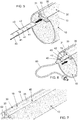
- the LED strip 40 is inserted inside the internal cavity 32 of the section bar 30 entering at the end 33 of the latter and then making it slide along the longitudinal extension of the section bar itself (see Figures 5 and 6 ).
- the internal cavity 32 is configured (i.e. it is sized and shaped) at the same time to allow insertion by sliding and substantially stable locking inside it, preferably with a minimum clearance, of the LED strip 40.
- the cavity 32 is sized and shaped to accommodate the LED strip 40 inside it so as to leave the latter a minimum displacement in the directions perpendicular to the insertion direction. More in detail, the cavity 32 has a shape such as to allow the insertion of the LED strip 40 and is slightly larger than the latter.
- the cavity 32 is internally delimited by a continuous surface, i.e. devoid of discontinuities, projections or appendages.
- the LED strip 40 is inserted removably inside the cavity 32 of the section bar 30, so that it can be replaced in case of failure of one or more LED diodes of the strip itself.
- the LED strip 40 can be easily removed from one of the ends 33 of the cavity 32 of the section bar 30, which for this purpose can be left open, i.e. not having plugs, nets, or other elements that allow their closure and/or or sealing.
- the protection of the LED diodes 41 is guaranteed by the fact that the LED strip 4 already alone is protected against dust penetration and against any penetration of liquid substances.
- the ends 33 of the cavity 32 of the section bar 30 are and always remain open towards the outside, i.e. there are no plugs, covers or other closing elements.
- the LED strip 40 protrudes from one or both ends 33 of the section bar 30, however - having a high IP protection degree (as defined above) - the solid particles or liquids of the external environment cannot enter in contact with the LED diodes 41 or with the electronic circuits of a strip itself. Conveniently, in this way, the LED strip 40 is not affected by the problem of environmental humidity even if it protrudes and exits from the ends 33 of the section bar 30.
- the LED strip 40 can be entirely housed and hidden inside the internal cavity 32 of the section bar 30 and, appropriately, in this case, it may be shorter than the longitudinal extension of the section. Suitably, this allows to avoid having to necessarily cut the section bar 30 of length corresponding to the size of the LED strip 40.
- the LED strip 40 has a longitudinal development with a substantially rectangular cross-section.
- the LED strip 40 can be positioned inside the cavity 32, so as to be in contact with a first internal surface and in the section bar 30, and preferably so as to emit light toward a second surface (opposite/facing said first surface) of the same profiled element.
- the LED strip 40 is inserted inside the cavity 32 so that the width of the strip develops substantially parallel to the width of the section bar 30 in which it is inserted.
- the section bar 30 is made of silicone, but could also be made in PMMA, in PVC, both with and without additives, or - in general - it could be made of rubber or other polymeric material, both synthetic and natural, with high elasticity.
- the section bar 30 can also be made of Plexiglas.
- the section bar 30 is made of elastic and flexible material and this is advantageous in that it facilitates its assembly by interlocking inside corresponding grooves 11 formed on the metal sections 13 (such as for example those of the articulated arms 10 of Figs. 2- 5 ) of an element of the roofing installation.
- the section bar 30 is configured (i.e. it is sized and shaped) so that - once inserted into the longitudinal groove 11 provided in the metal section 13 of an element 10 of the covering installation - it is substantially flush with the outer surface of the metal section itself, that is, without protruding radially from the latter.
- section bar 30 can be configured so as to act as a seal for an element of the roof installation.
- the section bar 30 comprises entirely, or at least in a part thereof, a portion 35 that transmits the light produced by the LED diodes 41 of the LED strip 40.
- the portion 35 is also configured to spread evenly the light produced by the LED diodes 41 of the LED strip 40.
- said portion 35 of the section bar 30 is configured to allow the transmission towards the external environment of the light generated by said LED strip 40 with an indicative loss of between about 0-50%.
- the section bar 30 comprises - in all its longitudinal extension or at least in a part thereof - a transparent or translucent portion to allow the total transmission of the light produced by the LED diodes 41 of the LED strip 40 (i.e. with a loss of about 0%).
- the section bar 30 comprises - in its entire longitudinal development or at least in a part thereof - a portion partially opaque, preferably with opal effect, frost (i.e. transparent or with frosted finish) or milky white, to allow at the same time the transmission and the homogeneous diffusion of the light produced by the LED diodes 41 of the LED strip 40.
- frost i.e. transparent or with frosted finish
- milky white a uniform lighting effect is obtained, i.e. avoiding the "dots" effect (that is, of several distinct lights separate from each other).
- the section bar 30 comprises at least two portions with different characteristics of both transmission and diffusion of the light produced by the LED diodes 41 of the LED strip 40.
- these two or more portions of the section bar 30 are obtained by using two or more different materials that are extruded together during the construction of the profile itself.
- an electric cable 60 is associated with the LED strip 40 - preferably at one of its end portion - for connection to a power supply source, not shown, such as for example a battery or the mains.
- the cables 60 connected to the LED strip 40 of the lighting devices 18 are electrically conductive connecting cables inside the components of the covering installation and, therefore, are hidden from view from the outside.
- the LED strip 40 of device or lighting 18 is also connected to a control device (not shown).
- the control device is of the type described in the Italian patent application 102017000090501 .
- control device comprises a power supply connected to the mains supply or to a battery, and a processor which is preferably configured to perform a pulse width modulation (PWM) of the supply voltage of the LED diodes 41 of the strip 40.
- processor is configured also to allow the wireless connection (preferably radio, via infrared, wi-fi...) with an external device (such as a remote control) to command the activation/deactivation of the LEDs 41, and the variation in brightness generated by these.
- the lighting device described here differs from US 2012/0182755 , WO 2005/106320 and US 2011/0007514 in that the LED strip comprises a protective casing/covering - inside which the LED diodes are provided - such as to make the strip itself, already on its own, protected against the penetration of dust and against any penetration of liquid substances.
- the LED strip comprises a protective casing/covering - inside which the LED diodes are provided - such as to make the strip itself, already on its own, protected against the penetration of dust and against any penetration of liquid substances.
- This is particularly advantageous in that, while allowing the LED strip to be removed from the section bar for its replacement, it causes the strip itself to be partially housed outside the containment section, as well as allowing an open section to be provided which is not sealed at the ends (i.e. without caps, lids or other closing end elements), thus simplifying both the production of the section bar and the installation/removal of the strip in/from said section bar.
Landscapes
- Engineering & Computer Science (AREA)
- General Engineering & Computer Science (AREA)
- Architecture (AREA)
- Civil Engineering (AREA)
- Structural Engineering (AREA)
- Non-Portable Lighting Devices Or Systems Thereof (AREA)
- Endoscopes (AREA)
- Circuit Arrangement For Electric Light Sources In General (AREA)
Applications Claiming Priority (1)
| Application Number | Priority Date | Filing Date | Title |
|---|---|---|---|
| IT102018000007704A IT201800007704A1 (it) | 2018-07-31 | 2018-07-31 | Dispositivo di illuminazione perfezionato |
Publications (2)
| Publication Number | Publication Date |
|---|---|
| EP3604913A1 EP3604913A1 (en) | 2020-02-05 |
| EP3604913B1 true EP3604913B1 (en) | 2021-05-05 |
Family
ID=64049544
Family Applications (1)
| Application Number | Title | Priority Date | Filing Date |
|---|---|---|---|
| EP19188671.2A Active EP3604913B1 (en) | 2018-07-31 | 2019-07-26 | An improved lighting device |
Country Status (3)
| Country | Link |
|---|---|
| EP (1) | EP3604913B1 (it) |
| ES (1) | ES2887701T3 (it) |
| IT (1) | IT201800007704A1 (it) |
Cited By (1)
| Publication number | Priority date | Publication date | Assignee | Title |
|---|---|---|---|---|
| DE102021206111A1 (de) | 2021-06-15 | 2022-12-15 | Wolfgang Rixen | Profilleiste, Stecker sowie Baugruppe aus Strukturbauteil, Profilleiste und Stecker |
Families Citing this family (3)
| Publication number | Priority date | Publication date | Assignee | Title |
|---|---|---|---|---|
| IT202000010267A1 (it) * | 2020-05-07 | 2021-11-07 | Teleco Automation Srl | Dispositivo di sanificazione perfezionato |
| CN112696620A (zh) * | 2021-01-14 | 2021-04-23 | 中山市美耐特光电有限公司 | 一种便于安装的灯带包覆套及其led灯带 |
| EP4345367A1 (en) | 2022-09-29 | 2024-04-03 | Linea Light S.R.L. | Lighting apparatus |
Family Cites Families (6)
| Publication number | Priority date | Publication date | Assignee | Title |
|---|---|---|---|---|
| US7213941B2 (en) * | 2004-04-14 | 2007-05-08 | Sloanled, Inc. | Flexible perimeter lighting apparatus |
| DE102006031345A1 (de) * | 2006-07-06 | 2008-01-10 | Patent-Treuhand-Gesellschaft für elektrische Glühlampen mbH | Formflexibles Beleuchtungssystem |
| US8398262B2 (en) * | 2008-05-09 | 2013-03-19 | The Sloan Company, Inc. | Low profile extrusion |
| FR2989100B1 (fr) * | 2012-04-06 | 2014-04-25 | Christophe Dourdou | Piece allongee de structure integrant une source lumineuse |
| EP3196550B1 (en) * | 2016-01-20 | 2018-10-24 | OSRAM GmbH | A method of producing lighting devices and corresponding lighting device |
| IT201700090501A1 (it) | 2017-08-04 | 2019-02-04 | Teleco Automation Srl | Dispositivo di controllo delle luci di una tenda avvolgibile motorizzata |
-
2018
- 2018-07-31 IT IT102018000007704A patent/IT201800007704A1/it unknown
-
2019
- 2019-07-26 EP EP19188671.2A patent/EP3604913B1/en active Active
- 2019-07-26 ES ES19188671T patent/ES2887701T3/es active Active
Cited By (1)
| Publication number | Priority date | Publication date | Assignee | Title |
|---|---|---|---|---|
| DE102021206111A1 (de) | 2021-06-15 | 2022-12-15 | Wolfgang Rixen | Profilleiste, Stecker sowie Baugruppe aus Strukturbauteil, Profilleiste und Stecker |
Also Published As
| Publication number | Publication date |
|---|---|
| ES2887701T3 (es) | 2021-12-27 |
| IT201800007704A1 (it) | 2020-01-31 |
| EP3604913A1 (en) | 2020-02-05 |
Similar Documents
| Publication | Publication Date | Title |
|---|---|---|
| EP3604913B1 (en) | An improved lighting device | |
| US10180220B2 (en) | Architectural lighting methods and apparatus | |
| EP2850363B1 (en) | Edge lit luminaires for windows | |
| US8398262B2 (en) | Low profile extrusion | |
| US8388214B1 (en) | Lighted railing and similar structures | |
| US20200208408A1 (en) | Control device for the lighting elements to be mounted on a roller covering installation | |
| DE50110997D1 (de) | Fensterrollo mit vereinfachter Montage | |
| WO2010132078A1 (en) | Low profile extrusion | |
| JP2016066449A (ja) | 発光装置 | |
| EP3604912B1 (en) | An improved section bar | |
| CN112785934A (zh) | Led单元板及显示屏 | |
| US10641471B1 (en) | Retractable holiday lights | |
| KR20110096818A (ko) | 엘이디 끝발광기능을 갖는 커튼 월 | |
| EP1443172A3 (en) | Electrical connection unit for motorised systems of shades, roll-up blinds and rolling shutters in general | |
| KR101554838B1 (ko) | 열차단 블라인드 | |
| GB2516614A (en) | Photoluminescent devices suited for a broad range of applications | |
| US20150338063A1 (en) | Photoluminescent devices suited for a broad range of applications | |
| IT201800003146U1 (it) | Dispositivo di illuminazione perfezionato | |
| CA2852205C (en) | Blind motor control | |
| US20170363264A1 (en) | Screened enclosure lighting system | |
| DE69903758D1 (de) | Fensterrollo mit einem biegsamen Gehäuse | |
| IT201800003148U1 (it) | Profilato perfezionato | |
| KR101186785B1 (ko) | 차양장치 | |
| IT202000010267A1 (it) | Dispositivo di sanificazione perfezionato | |
| KR102204019B1 (ko) | 조립식 화장실의 조명장치 |
Legal Events
| Date | Code | Title | Description |
|---|---|---|---|
| PUAI | Public reference made under article 153(3) epc to a published international application that has entered the european phase |
Free format text: ORIGINAL CODE: 0009012 |
|
| STAA | Information on the status of an ep patent application or granted ep patent |
Free format text: STATUS: THE APPLICATION HAS BEEN PUBLISHED |
|
| AK | Designated contracting states |
Kind code of ref document: A1 Designated state(s): AL AT BE BG CH CY CZ DE DK EE ES FI FR GB GR HR HU IE IS IT LI LT LU LV MC MK MT NL NO PL PT RO RS SE SI SK SM TR |
|
| AX | Request for extension of the european patent |
Extension state: BA ME |
|
| STAA | Information on the status of an ep patent application or granted ep patent |
Free format text: STATUS: REQUEST FOR EXAMINATION WAS MADE |
|
| 17P | Request for examination filed |
Effective date: 20200804 |
|
| RBV | Designated contracting states (corrected) |
Designated state(s): AL AT BE BG CH CY CZ DE DK EE ES FI FR GB GR HR HU IE IS IT LI LT LU LV MC MK MT NL NO PL PT RO RS SE SI SK SM TR |
|
| GRAP | Despatch of communication of intention to grant a patent |
Free format text: ORIGINAL CODE: EPIDOSNIGR1 |
|
| STAA | Information on the status of an ep patent application or granted ep patent |
Free format text: STATUS: GRANT OF PATENT IS INTENDED |
|
| INTG | Intention to grant announced |
Effective date: 20201125 |
|
| GRAJ | Information related to disapproval of communication of intention to grant by the applicant or resumption of examination proceedings by the epo deleted |
Free format text: ORIGINAL CODE: EPIDOSDIGR1 |
|
| STAA | Information on the status of an ep patent application or granted ep patent |
Free format text: STATUS: REQUEST FOR EXAMINATION WAS MADE |
|
| INTC | Intention to grant announced (deleted) | ||
| GRAS | Grant fee paid |
Free format text: ORIGINAL CODE: EPIDOSNIGR3 |
|
| STAA | Information on the status of an ep patent application or granted ep patent |
Free format text: STATUS: GRANT OF PATENT IS INTENDED |
|
| GRAP | Despatch of communication of intention to grant a patent |
Free format text: ORIGINAL CODE: EPIDOSNIGR1 |
|
| GRAA | (expected) grant |
Free format text: ORIGINAL CODE: 0009210 |
|
| STAA | Information on the status of an ep patent application or granted ep patent |
Free format text: STATUS: THE PATENT HAS BEEN GRANTED |
|
| INTG | Intention to grant announced |
Effective date: 20210329 |
|
| AK | Designated contracting states |
Kind code of ref document: B1 Designated state(s): AL AT BE BG CH CY CZ DE DK EE ES FI FR GB GR HR HU IE IS IT LI LT LU LV MC MK MT NL NO PL PT RO RS SE SI SK SM TR |
|
| REG | Reference to a national code |
Ref country code: GB Ref legal event code: FG4D |
|
| REG | Reference to a national code |
Ref country code: CH Ref legal event code: EP |
|
| REG | Reference to a national code |
Ref country code: AT Ref legal event code: REF Ref document number: 1390259 Country of ref document: AT Kind code of ref document: T Effective date: 20210515 |
|
| REG | Reference to a national code |
Ref country code: IE Ref legal event code: FG4D |
|
| REG | Reference to a national code |
Ref country code: DE Ref legal event code: R096 Ref document number: 602019004438 Country of ref document: DE |
|
| REG | Reference to a national code |
Ref country code: LT Ref legal event code: MG9D |
|
| REG | Reference to a national code |
Ref country code: AT Ref legal event code: MK05 Ref document number: 1390259 Country of ref document: AT Kind code of ref document: T Effective date: 20210505 |
|
| PG25 | Lapsed in a contracting state [announced via postgrant information from national office to epo] |
Ref country code: FI Free format text: LAPSE BECAUSE OF FAILURE TO SUBMIT A TRANSLATION OF THE DESCRIPTION OR TO PAY THE FEE WITHIN THE PRESCRIBED TIME-LIMIT Effective date: 20210505 Ref country code: LT Free format text: LAPSE BECAUSE OF FAILURE TO SUBMIT A TRANSLATION OF THE DESCRIPTION OR TO PAY THE FEE WITHIN THE PRESCRIBED TIME-LIMIT Effective date: 20210505 Ref country code: HR Free format text: LAPSE BECAUSE OF FAILURE TO SUBMIT A TRANSLATION OF THE DESCRIPTION OR TO PAY THE FEE WITHIN THE PRESCRIBED TIME-LIMIT Effective date: 20210505 Ref country code: AT Free format text: LAPSE BECAUSE OF FAILURE TO SUBMIT A TRANSLATION OF THE DESCRIPTION OR TO PAY THE FEE WITHIN THE PRESCRIBED TIME-LIMIT Effective date: 20210505 Ref country code: BG Free format text: LAPSE BECAUSE OF FAILURE TO SUBMIT A TRANSLATION OF THE DESCRIPTION OR TO PAY THE FEE WITHIN THE PRESCRIBED TIME-LIMIT Effective date: 20210805 |
|
| PG25 | Lapsed in a contracting state [announced via postgrant information from national office to epo] |
Ref country code: LV Free format text: LAPSE BECAUSE OF FAILURE TO SUBMIT A TRANSLATION OF THE DESCRIPTION OR TO PAY THE FEE WITHIN THE PRESCRIBED TIME-LIMIT Effective date: 20210505 Ref country code: NO Free format text: LAPSE BECAUSE OF FAILURE TO SUBMIT A TRANSLATION OF THE DESCRIPTION OR TO PAY THE FEE WITHIN THE PRESCRIBED TIME-LIMIT Effective date: 20210805 Ref country code: PL Free format text: LAPSE BECAUSE OF FAILURE TO SUBMIT A TRANSLATION OF THE DESCRIPTION OR TO PAY THE FEE WITHIN THE PRESCRIBED TIME-LIMIT Effective date: 20210505 Ref country code: PT Free format text: LAPSE BECAUSE OF FAILURE TO SUBMIT A TRANSLATION OF THE DESCRIPTION OR TO PAY THE FEE WITHIN THE PRESCRIBED TIME-LIMIT Effective date: 20210906 Ref country code: SE Free format text: LAPSE BECAUSE OF FAILURE TO SUBMIT A TRANSLATION OF THE DESCRIPTION OR TO PAY THE FEE WITHIN THE PRESCRIBED TIME-LIMIT Effective date: 20210505 Ref country code: RS Free format text: LAPSE BECAUSE OF FAILURE TO SUBMIT A TRANSLATION OF THE DESCRIPTION OR TO PAY THE FEE WITHIN THE PRESCRIBED TIME-LIMIT Effective date: 20210505 Ref country code: IS Free format text: LAPSE BECAUSE OF FAILURE TO SUBMIT A TRANSLATION OF THE DESCRIPTION OR TO PAY THE FEE WITHIN THE PRESCRIBED TIME-LIMIT Effective date: 20210905 Ref country code: GR Free format text: LAPSE BECAUSE OF FAILURE TO SUBMIT A TRANSLATION OF THE DESCRIPTION OR TO PAY THE FEE WITHIN THE PRESCRIBED TIME-LIMIT Effective date: 20210806 |
|
| REG | Reference to a national code |
Ref country code: NL Ref legal event code: MP Effective date: 20210505 |
|
| REG | Reference to a national code |
Ref country code: ES Ref legal event code: FG2A Ref document number: 2887701 Country of ref document: ES Kind code of ref document: T3 Effective date: 20211227 |
|
| PG25 | Lapsed in a contracting state [announced via postgrant information from national office to epo] |
Ref country code: NL Free format text: LAPSE BECAUSE OF FAILURE TO SUBMIT A TRANSLATION OF THE DESCRIPTION OR TO PAY THE FEE WITHIN THE PRESCRIBED TIME-LIMIT Effective date: 20210505 |
|
| PG25 | Lapsed in a contracting state [announced via postgrant information from national office to epo] |
Ref country code: CZ Free format text: LAPSE BECAUSE OF FAILURE TO SUBMIT A TRANSLATION OF THE DESCRIPTION OR TO PAY THE FEE WITHIN THE PRESCRIBED TIME-LIMIT Effective date: 20210505 Ref country code: DK Free format text: LAPSE BECAUSE OF FAILURE TO SUBMIT A TRANSLATION OF THE DESCRIPTION OR TO PAY THE FEE WITHIN THE PRESCRIBED TIME-LIMIT Effective date: 20210505 Ref country code: RO Free format text: LAPSE BECAUSE OF FAILURE TO SUBMIT A TRANSLATION OF THE DESCRIPTION OR TO PAY THE FEE WITHIN THE PRESCRIBED TIME-LIMIT Effective date: 20210505 Ref country code: SM Free format text: LAPSE BECAUSE OF FAILURE TO SUBMIT A TRANSLATION OF THE DESCRIPTION OR TO PAY THE FEE WITHIN THE PRESCRIBED TIME-LIMIT Effective date: 20210505 Ref country code: SK Free format text: LAPSE BECAUSE OF FAILURE TO SUBMIT A TRANSLATION OF THE DESCRIPTION OR TO PAY THE FEE WITHIN THE PRESCRIBED TIME-LIMIT Effective date: 20210505 Ref country code: EE Free format text: LAPSE BECAUSE OF FAILURE TO SUBMIT A TRANSLATION OF THE DESCRIPTION OR TO PAY THE FEE WITHIN THE PRESCRIBED TIME-LIMIT Effective date: 20210505 |
|
| REG | Reference to a national code |
Ref country code: DE Ref legal event code: R097 Ref document number: 602019004438 Country of ref document: DE |
|
| PLBE | No opposition filed within time limit |
Free format text: ORIGINAL CODE: 0009261 |
|
| STAA | Information on the status of an ep patent application or granted ep patent |
Free format text: STATUS: NO OPPOSITION FILED WITHIN TIME LIMIT |
|
| PG25 | Lapsed in a contracting state [announced via postgrant information from national office to epo] |
Ref country code: MC Free format text: LAPSE BECAUSE OF FAILURE TO SUBMIT A TRANSLATION OF THE DESCRIPTION OR TO PAY THE FEE WITHIN THE PRESCRIBED TIME-LIMIT Effective date: 20210505 |
|
| 26N | No opposition filed |
Effective date: 20220208 |
|
| PG25 | Lapsed in a contracting state [announced via postgrant information from national office to epo] |
Ref country code: IS Free format text: LAPSE BECAUSE OF FAILURE TO SUBMIT A TRANSLATION OF THE DESCRIPTION OR TO PAY THE FEE WITHIN THE PRESCRIBED TIME-LIMIT Effective date: 20210905 Ref country code: LU Free format text: LAPSE BECAUSE OF NON-PAYMENT OF DUE FEES Effective date: 20210726 Ref country code: AL Free format text: LAPSE BECAUSE OF FAILURE TO SUBMIT A TRANSLATION OF THE DESCRIPTION OR TO PAY THE FEE WITHIN THE PRESCRIBED TIME-LIMIT Effective date: 20210505 |
|
| PG25 | Lapsed in a contracting state [announced via postgrant information from national office to epo] |
Ref country code: IE Free format text: LAPSE BECAUSE OF NON-PAYMENT OF DUE FEES Effective date: 20210726 |
|
| REG | Reference to a national code |
Ref country code: CH Ref legal event code: PL |
|
| PG25 | Lapsed in a contracting state [announced via postgrant information from national office to epo] |
Ref country code: LI Free format text: LAPSE BECAUSE OF NON-PAYMENT OF DUE FEES Effective date: 20220731 Ref country code: CH Free format text: LAPSE BECAUSE OF NON-PAYMENT OF DUE FEES Effective date: 20220731 |
|
| PG25 | Lapsed in a contracting state [announced via postgrant information from national office to epo] |
Ref country code: CY Free format text: LAPSE BECAUSE OF FAILURE TO SUBMIT A TRANSLATION OF THE DESCRIPTION OR TO PAY THE FEE WITHIN THE PRESCRIBED TIME-LIMIT Effective date: 20210505 |
|
| PG25 | Lapsed in a contracting state [announced via postgrant information from national office to epo] |
Ref country code: HU Free format text: LAPSE BECAUSE OF FAILURE TO SUBMIT A TRANSLATION OF THE DESCRIPTION OR TO PAY THE FEE WITHIN THE PRESCRIBED TIME-LIMIT; INVALID AB INITIO Effective date: 20190726 |
|
| GBPC | Gb: european patent ceased through non-payment of renewal fee |
Effective date: 20230726 |
|
| PG25 | Lapsed in a contracting state [announced via postgrant information from national office to epo] |
Ref country code: MK Free format text: LAPSE BECAUSE OF FAILURE TO SUBMIT A TRANSLATION OF THE DESCRIPTION OR TO PAY THE FEE WITHIN THE PRESCRIBED TIME-LIMIT Effective date: 20210505 Ref country code: GB Free format text: LAPSE BECAUSE OF NON-PAYMENT OF DUE FEES Effective date: 20230726 |
|
| PG25 | Lapsed in a contracting state [announced via postgrant information from national office to epo] |
Ref country code: TR Free format text: LAPSE BECAUSE OF FAILURE TO SUBMIT A TRANSLATION OF THE DESCRIPTION OR TO PAY THE FEE WITHIN THE PRESCRIBED TIME-LIMIT Effective date: 20210505 |
|
| PG25 | Lapsed in a contracting state [announced via postgrant information from national office to epo] |
Ref country code: MT Free format text: LAPSE BECAUSE OF FAILURE TO SUBMIT A TRANSLATION OF THE DESCRIPTION OR TO PAY THE FEE WITHIN THE PRESCRIBED TIME-LIMIT Effective date: 20210505 |
|
| PGFP | Annual fee paid to national office [announced via postgrant information from national office to epo] |
Ref country code: BE Payment date: 20250624 Year of fee payment: 7 |
|
| PGFP | Annual fee paid to national office [announced via postgrant information from national office to epo] |
Ref country code: FR Payment date: 20250617 Year of fee payment: 7 |
|
| PGFP | Annual fee paid to national office [announced via postgrant information from national office to epo] |
Ref country code: ES Payment date: 20250812 Year of fee payment: 7 |
|
| PGFP | Annual fee paid to national office [announced via postgrant information from national office to epo] |
Ref country code: DE Payment date: 20250624 Year of fee payment: 7 |
|
| PGFP | Annual fee paid to national office [announced via postgrant information from national office to epo] |
Ref country code: IT Payment date: 20250617 Year of fee payment: 7 |