EP3604873A1 - Membran mit lasche - Google Patents
Membran mit lasche Download PDFInfo
- Publication number
- EP3604873A1 EP3604873A1 EP18187200.3A EP18187200A EP3604873A1 EP 3604873 A1 EP3604873 A1 EP 3604873A1 EP 18187200 A EP18187200 A EP 18187200A EP 3604873 A1 EP3604873 A1 EP 3604873A1
- Authority
- EP
- European Patent Office
- Prior art keywords
- membrane
- diaphragm
- component
- predetermined breaking
- breaking point
- Prior art date
- Legal status (The legal status is an assumption and is not a legal conclusion. Google has not performed a legal analysis and makes no representation as to the accuracy of the status listed.)
- Granted
Links
Images

Classifications
-
- F—MECHANICAL ENGINEERING; LIGHTING; HEATING; WEAPONS; BLASTING
- F16—ENGINEERING ELEMENTS AND UNITS; GENERAL MEASURES FOR PRODUCING AND MAINTAINING EFFECTIVE FUNCTIONING OF MACHINES OR INSTALLATIONS; THERMAL INSULATION IN GENERAL
- F16K—VALVES; TAPS; COCKS; ACTUATING-FLOATS; DEVICES FOR VENTING OR AERATING
- F16K7/00—Diaphragm valves or cut-off apparatus, e.g. with a member deformed, but not moved bodily, to close the passage ; Pinch valves
- F16K7/12—Diaphragm valves or cut-off apparatus, e.g. with a member deformed, but not moved bodily, to close the passage ; Pinch valves with flat, dished, or bowl-shaped diaphragm
- F16K7/126—Diaphragm valves or cut-off apparatus, e.g. with a member deformed, but not moved bodily, to close the passage ; Pinch valves with flat, dished, or bowl-shaped diaphragm the seat being formed on a rib perpendicular to the fluid line
-
- F—MECHANICAL ENGINEERING; LIGHTING; HEATING; WEAPONS; BLASTING
- F04—POSITIVE - DISPLACEMENT MACHINES FOR LIQUIDS; PUMPS FOR LIQUIDS OR ELASTIC FLUIDS
- F04B—POSITIVE-DISPLACEMENT MACHINES FOR LIQUIDS; PUMPS
- F04B43/00—Machines, pumps, or pumping installations having flexible working members
- F04B43/0009—Special features
- F04B43/0054—Special features particularities of the flexible members
-
- F—MECHANICAL ENGINEERING; LIGHTING; HEATING; WEAPONS; BLASTING
- F04—POSITIVE - DISPLACEMENT MACHINES FOR LIQUIDS; PUMPS FOR LIQUIDS OR ELASTIC FLUIDS
- F04B—POSITIVE-DISPLACEMENT MACHINES FOR LIQUIDS; PUMPS
- F04B43/00—Machines, pumps, or pumping installations having flexible working members
- F04B43/02—Machines, pumps, or pumping installations having flexible working members having plate-like flexible members, e.g. diaphragms
-
- G—PHYSICS
- G06—COMPUTING OR CALCULATING; COUNTING
- G06K—GRAPHICAL DATA READING; PRESENTATION OF DATA; RECORD CARRIERS; HANDLING RECORD CARRIERS
- G06K19/00—Record carriers for use with machines and with at least a part designed to carry digital markings
- G06K19/06—Record carriers for use with machines and with at least a part designed to carry digital markings characterised by the kind of the digital marking, e.g. shape, nature, code
- G06K19/067—Record carriers with conductive marks, printed circuits or semiconductor circuit elements, e.g. credit or identity cards also with resonating or responding marks without active components
- G06K19/07—Record carriers with conductive marks, printed circuits or semiconductor circuit elements, e.g. credit or identity cards also with resonating or responding marks without active components with integrated circuit chips
- G06K19/0723—Record carriers with conductive marks, printed circuits or semiconductor circuit elements, e.g. credit or identity cards also with resonating or responding marks without active components with integrated circuit chips the record carrier comprising an arrangement for non-contact communication, e.g. wireless communication circuits on transponder cards, non-contact smart cards or RFIDs
Definitions
- the invention relates to membranes in valves or pumps with a tab, and a method for recycling a membrane.
- the WO2012035291 describes a method and a device for diagnosing a diaphragm valve.
- the DE 10 2015 210 208 A1 describes the determination of state variables in valve membranes.
- the object of the invention is to provide a membrane for valves and / or pumps in which at least one data memory is provided, the data memory being able to be integrated in the membrane in different ways.
- the requirements regarding cleanability and hygiene should be high.
- the membrane should be simple and inexpensive to manufacture and individual components should be separable after use and possibly recyclable.
- the diaphragm of a diaphragm valve or a diaphragm pump comprising a first component, consisting of a diaphragm which can be provided in a housing, consisting of a plurality of diaphragm systems, part of the diaphragm protruding from the housing and forming the so-called flap, and comprehensively a second Component, the second component being arranged in the part of the flap, a predetermined breaking point being provided between the flap and the remaining membrane.
- the flap is arranged so that it can be torn off the membrane.
- the advantage here is that a simple, tool-free separation of the flap and membrane is possible.
- a reinforcing element is incorporated into the membrane, the reinforcing element not being provided in the area of the predetermined breaking point.
- Fabrics or full-surface intermediate layers serve as reinforcing elements.
- an aid for cutting the membrane can be provided along the predetermined breaking point, in particular a cutting thread or a cutting film. This further simplifies the separation. Without tools, it would still be understood as without additional tools.
- the second component is a data memory, this comprising any form of electrical or electronic component, in particular means for recording, measuring, processing, storing and / or forwarding status and / or status variables which are in or on the membrane are detectable.
- the advantage here is that the individual Components of the membrane can be recycled in a simple and inexpensive manner.
- the separation of electronics and elastomer is difficult if the composite is designed in such a way that the electronics are embedded in the elastomer. A separation can often only be carried out after thermal destruction of the elastomer.
- FIG. 1 shows a membrane 1, as used for example in a membrane valve or a membrane pump.
- the membrane 1 is constructed, for example, from several layers of elastomeric material 1a, 1b, which can be provided with a reinforcement, for example a fabric, if necessary.
- This membrane has a so-called tab 2, which is also referred to as a tab or flag. If the membrane is mounted in a valve or pump housing, this tab 2 protrudes over the actual working surface of the membrane.
- the membrane can also have a special shape, which provides additional advantages through a chamber. This configuration is not shown in the figure. Part of the tab 3 protrudes separately from the housing of the valve or the pump.
- a data memory 4 in particular an electronic data memory, can also may have means for data acquisition, data processing and data transfer.
- the membrane 1 is fastened in a valve or pump housing and moved by an actuator, whereby, for example, a valve can be opened or closed or the pumping effect can be achieved.
- the flap is made from at least one layer of elastomeric material.
- the other layers of the membrane do not necessarily protrude into the area of the flap 3.
- a data memory 4 in the tab 3.
- This data memory 4 can be designed, for example, as a purely passive element and contain an identity label for the membrane 1.
- the history and use of the membrane can be derived from the data of a corresponding database, for example, by means of a unique number.
- it can also be connected to a data acquisition device, for example a sensor, for which it stores the acquired data.
- a transmitting and receiving device for transmitting data can be provided in the data memory.
- the data memory 4 can either be read out by direct contact with a reading device or a contactless data reading takes place, for example using an RFID technology or the like.
- the data storage device 4 can have its own energy supply, or can be supplied by the reading device.
- the arrangement of a predetermined breaking point 5 between the tab 3 protruding from the housing and the tab 2 located in the housing is essential for the membrane.
- the tab 3 can be separated from the remaining tab 2 without tools.
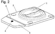
- Fig. 2 shows an oblique view of a membrane according to the invention, the details of a concrete membrane device are clearly formed.
Landscapes
- Engineering & Computer Science (AREA)
- General Engineering & Computer Science (AREA)
- Mechanical Engineering (AREA)
- Computer Networks & Wireless Communication (AREA)
- Computer Hardware Design (AREA)
- Microelectronics & Electronic Packaging (AREA)
- Physics & Mathematics (AREA)
- General Physics & Mathematics (AREA)
- Theoretical Computer Science (AREA)
- Reciprocating Pumps (AREA)
Abstract
Description
- Die Erfindung betrifft Membranen in Ventilen oder Pumpen mit einer Lasche, sowie ein Verfahren zum Recyceln einer Membran.
- Die Überwachung oder Diagnose von Membranen in Ventilen und Pumpen ist insbesondere in kritischen Bereichen der sterilen Verfahrenstechnik ein deutlicher Schwerpunkt, dem im Wesentlichen durch vorsorgende Maßnahmen begegnet wird, da fortlaufend gemessene Zustandsgrößen weitestgehend nicht verfügbar sind. Messungen während des laufenden Betriebes sind teilweise nur schwer möglich. Anlagen müssen oft in allen Details steril reinigbar aufgebaut sein, weshalb übliche elektrische Stecker Anordnungen ungünstig sind. Eine Möglichkeit der Erfassung von Zustandsgrößen ist die Integration von Messgeräten in die Membran. Nach Ihrem Einsatz besteht die verbrauchte Membran hauptsächlich aus Elastomer, wobei durch genannte Integration von Messgeräten mindestens ein Elektronikbauteil enthalten ist.
- In der
DE 10 2013 214 304 A1 wird ein Verfahren und eine Vorrichtung zum Auslesen und Sammeln von Daten aus einer Membran beschrieben. - Die
WO2012035291 beschreibt ein Verfahren und eine Vorrichtung zur Diagnose eines Membranventils. - Die
DE 10 2015 210 208 A1 beschreibt die Ermittlung von Zustandsgrößen bei Ventilmembranen. - Aufgabe der Erfindung ist es, eine Membran für Ventile und/oder Pumpen zu schaffen, bei der mindestens ein Datenspeicher vorgesehen ist, wobei der Datenspeicher auf unterschiedliche Art in der Membran integriert sein kann. Anforderungen bezüglich der Reinigbarkeit und der Hygiene sollen hoch sein. Weiter soll die Membran einfach und kostengünstig herstellbar sein und einzelne Komponenten sollen nach Gebrauch trennbar und eventuell wiederverwertbar sein.
- Diese Aufgabe wird erfindungsgemäß durch eine Vorrichtung mit den Merkmalen des Anspruchs 1 gelöst. Vorgesehen ist dabei, dass die Membran eines Membranventils oder einer Membranpumpe umfassend ein erstes Bauteil, bestehend aus einer in einem Gehäuse vorsehbaren Membran, bestehend aus mehreren Membranlagen, wobei ein Teil der Membran aus dem Gehäuse herausragt und den sogenannten Lappen bildet, und umfassend ein zweites Bauteil, wobei das zweite Bauteil in die Teil des Lappens angeordnet ist, wobei zwischen dem Lappen und der übrigen Membran eine Sollbruchstelle vorgesehen ist. Dies hat den Vorteil, dass die beiden Bereiche des Lappens, also der um die Membran angeordnete und der das zweite Bauteil enthaltende, auf einfache, definierte Weise trennbar sind.
- Dies hat den Vorteil, dass eine einfache Nutzung einer Membran mit einem Datenspeicher möglich ist. Je nach Anwendungsgebiet fallen bei den Nutzern deutliche Mengen benötigter Membranen an. Diese sind erfindungsgemäß jeweils aus ihren einzelnen Bestandteilen herzustellen, woraus ein Verbundbauteil aus Elastomer, Verstärkungsmaterial und Datenspeicher entsteht. Nach Gebrauch der Membran kann dieser Datenspeicher eventuell zur Wiederverwendung aus der Membran entnommen werden. Wesentlich wird es hierfür sein, die mechanischen von den elektronischen Komponenten zu trennen. Mechanisch bedeutet in diesem Fall also das reine Membranmaterial, das meist aus einem Elastomer besteht, der eventuell durch eine beliebige Armierung verstärkt ausgeführt ist. Als elektronische Komponenten, hier Datenspeicher genannt, sind auch sämtliche weiteren elektronischen Bauteile zu verstehen. Hierzu zählen einfache Kontaktierungen, Sensoren, Datenspeicher oder komplexere Bauteile, beispielsweise zur Datenanalyse.
- In einer Ausgestaltung der Erfindung ist der Lappen von der Membran abreißbar angeordnet. Von Vorteil ist dabei, dass eine einfache, werkzeuglose Trennung von Lappen und Membran möglich ist.
- In einer weiteren vorteilhaften Ausgestaltung ist in die Membran ein Verstärkungselement eingearbeitet, wobei das Verstärkungselement nicht im Bereich der Sollbruchstelle vorgesehen ist. Als Verstärkungselement dienen Gewebe oder vollflächige Zwischenlagen. Von Vorteil ist dabei, dass die Trennung von Lappen und Membran vereinfacht ist. Zur weiteren Vereinfachung kann die Membran im Bereich der Sollbruchstelle perforiert sein, was die Trennbarkeit weiter erhöht.
- Ebenso kann in einer weiteren erfindungsgemäßen Ausgestaltung der Membran entlang der Sollbruchstelle ein Hilfsmittel zum Schneiden der Membran vorgesehen sein, insbesondere ein Schneidfaden oder eine Schneidfolie. Dies vereinfacht die Trennung zusätzlich. Werkzeuglos wäre dann immer noch als ohne zusätzliches Werkzeug zu verstehen.
- In einer weiteren Ausgestaltung der Erfindung ist das zweite Bauteil ein Datenspeicher, wobei dies jede Form von elektrischem oder elektronischem Bauteil umfasst, insbesondere Mittel zur Erfassung, Messung, Verarbeitung, Speicherung und/oder Weitergabe von Status- und/oder Zustandsgrößen, die in oder an der Membran erfassbar sind.
- Weiter ist es die Aufgabe der Erfindung eine Membran nach der vorbeschriebenen Art herzustellen, wobei in einem ersten Schritt die Membran regulär in einem Membranventil oder einer Membranpumpe mit einem Datenspeicher benutzt wird, in einem zweiten Schritt verbrauchte Membran aus dem Membranventil oder der Membranpumpe entfernt wird und in einem dritten Schritt der Lappen mit dem Datenspeicher entlang der Sollbruchstelle von der Membran getrennt wird. Von Vorteil ist dabei, dass die einzelnen Komponenten der Membran auf einfache und kostengünstige Weise der Wiederverwertung zugeführt werden können. Insbesondere die Trennung von Elektronik und Elastomer gestaltet sich schwierig, wenn der Verbund derart gestaltet ist, dass die Elektronik im Elastomer eingebettet ist. Häufig lässt sich eine Trennung nur nach thermischer Zerstörung des Elastomers durchführen.
- Weitere Vorteile ergeben sich, wenn im vorgestellten erfindungsgemäßen Verfahren Sollbruchstellen im Elastomer derart vorgesehen sind, dass der Datenspeicher werkzeuglos aus dem Elastomer entfernt werden kann.
- Weitere Merkmale und Vorteile der Erfindung ergeben sich aus der Beschreibung von Ausführungsbeispielen anhand von Zeichnungen und aus den Zeichnungen selbst.
- Dabei zeigt:
-
Figur 1 eine erfindungsgemäße Membran in einer Schnittansicht und die -
Figur 2 eine Schrägsicht auf eine erfindungsgemäße Membran. -
Figur 1 zeigt eine Membran 1, wie sie beispielsweise in einem Membranventil oder einer Membranpumpe zur Anwendung kommt. Die Membran 1 ist beispielsweise aus mehreren Lagen elastomeren Materials 1a, 1b aufgebaut, das bedarfsweise mit einer Verstärkung, beispielsweise einem Gewebe versehen sein kann. Diese Membran verfügt über einen sogenannten Lappen 2, der auch als Lasche oder Fahne bezeichnet wird. Ist die Membran in einem Ventil- oder Pumpengehäuse montiert, so ragt dieser Lappen 2 über die eigentliche Arbeitsfläche der Membran heraus. Die Membran kann zusätzlich über eine spezielle Form verfügen, die durch eine Kammerung für zusätzliche Vorteile sorgt. Diese Ausgestaltung ist in der Figur nicht dargestellt. Aus dem Gehäuse des Ventils oder der Pumpe ragt ein Teil des Lappens 3 in noch gesondert heraus. In diesem Lappen 3 kann ein Datenspeicher 4, insbesondere ein elektronischer Datenspeicher, der auch über Mittel zur Datenerfassung, zur Datenbearbeitung und zur Datenweitergabe verfügen kann. - Die Membran 1 wird in einem Ventil- oder Pumpengehäuse befestigt und durch einen Aktor bewegt, wodurch sich beispielsweise ein Ventil öffnen oder schließen oder die Pumpwirkung erzielen lässt.
- Erfindungsgemäß ist der Lappen aus mindestens einer Lage elastomeren Materials ausgestaltet. Die weiteren Lagen der Membran ragen nicht unbedingt in den Bereich des Lappens 3 vor. In dem Lappen 3 befindet sich erfindungsgemäß ein Datenspeicher 4. Dieser Datenspeicher 4 kann beispielsweise als rein passives Element ausgestaltet sein und eine Identitätskennzeichnung der Membran 1 enthalten. Durch eine eindeutige Nummer kann die Historie und Verwendung der Membran beispielsweise aus den Daten einer entsprechenden Datenbank entnommen werden. Er kann aber auch mit einer Datenerfassungsvorrichtung, beispielsweise einem Sensor verbunden sein, für den er die erfassten Daten speichert. Weiter kann bei dem Datenspeicher eine Sende- und Empfangsvorrichtung zur Übertragen von Daten vorgesehen sein.
- Der Datenspeicher 4 kann entweder durch direkten Kontakt mit einem Auslesegerät ausgelesen werden oder aber es findet eine kontaktlose Datenauslesung statt, beispielsweise über eine RFID Technik oder vergleichbares. Der Datenspeicher 4 kann über eine eigene Energieversorgung verfügen, oder aber durch das Auslesegerät versorgt werden.
- Wesentlich bei der Membran ist die Anordnung einer Sollbruchstelle 5 zwischen dem aus dem Gehäuse herausragenden Lappen 3 und dem im Gehäuse befindlichen Lappen 2. An diesem ist der Lappen 3 werkzeuglos vom übrigen Lappen 2 zu trennen.
- Die
Fig. 2 zeigt eine Schrägsicht auf eine erfindungsgemäße Membran, wobei die Details eine konkreten Membranvorrichtung deutlich ausgebildet sind. -
- 1
- Membran
- 1a, 1b
- Membranlage
- 2
- Lappen
- 3
- Lappen
- 4
- Datenspeicher
- 5
- Sollbruchstelle
Claims (8)
- Membran (1) eines Membranventils oder einer Membranpumpe umfassend ein erstes Bauteil, bestehend aus einer in einem Gehäuse vorgesehenen Membran (1), bestehend aus mehreren Membranlagen (1a, 1b), wobei ein Teil der Membran (1) aus dem Gehäuse herausragt und den sogenannten Lappen (2) bildet, und ein zweites Bauteil, wobei das zweite Bauteil in einem Teil des Lappens (3) angeordnet ist,
dadurch gekennzeichnet, dass
zwischen dem Lappen (3) und der übrigen Membran (1) eine Sollbruchstelle (5) vorgesehen ist. - Membran (1) nach Anspruch 1, dadurch gekennzeichnet, dass der Lappen (3) von der Membran (1) abreißbar angeordnet ist.
- Membran (1) nach Anspruch 1 oder 2, dadurch gekennzeichnet, dass in die Membran (1) ein Verstärkungselement eingearbeitet ist, wobei das Verstärkungselement nicht im Bereich der Sollbruchstelle (5) vorgesehen ist.
- Membran (1) nach einen der Ansprüche 1 bis 3, dadurch gekennzeichnet, dass im Bereich der Sollbruchstelle mindestens eine Membranlage perforiert ist.
- Membran (1) nach einem der Ansprüche 1 bis 4, dadurch gekennzeichnet, dass die Membran entlang der Sollbruchstelle (5) über ein Hilfsmittel zum Schneiden der Membran (1) verfügt, insbesondere einen Schneidfaden oder eine Schneidfolie.
- Membran (1) nach einem der Ansprüche 1 bis 5, dadurch gekennzeichnet, dass das zweite Bauteil ein Datenspeicher (4) ist.
- Verfahren zur Herstellung und Nutzung einer Membran (1) nach einem der vorherigen Ansprüche, dadurch gekennzeichnet, dass in einem ersten Schritt die Membran (1) regulär in einem Membranventil oder einer Membranpumpe mit einem Datenspeicher (5) benutzt wird, in einem zweiten Schritt die verbrauchte Membran (1) aus dem Membranventil oder der Membranpumpe entfernt wird und in einem dritten Schritt der Lappen (2) mit dem Datenspeicher (5) entlang der Sollbruchstelle von der Membran (1) getrennt wird.
- Verfahren zur Herstellung und Nutzung einer Membran (1) nach Anspruch 7,
dadurch gekennzeichnet, dass die einzelnen Komponenten der Wiederverwertung zugeführt werden.
Priority Applications (1)
| Application Number | Priority Date | Filing Date | Title |
|---|---|---|---|
| EP18187200.3A EP3604873B2 (de) | 2018-08-03 | 2018-08-03 | Membran mit lasche |
Applications Claiming Priority (1)
| Application Number | Priority Date | Filing Date | Title |
|---|---|---|---|
| EP18187200.3A EP3604873B2 (de) | 2018-08-03 | 2018-08-03 | Membran mit lasche |
Publications (3)
| Publication Number | Publication Date |
|---|---|
| EP3604873A1 true EP3604873A1 (de) | 2020-02-05 |
| EP3604873B1 EP3604873B1 (de) | 2021-06-02 |
| EP3604873B2 EP3604873B2 (de) | 2025-07-09 |
Family
ID=63144865
Family Applications (1)
| Application Number | Title | Priority Date | Filing Date |
|---|---|---|---|
| EP18187200.3A Active EP3604873B2 (de) | 2018-08-03 | 2018-08-03 | Membran mit lasche |
Country Status (1)
| Country | Link |
|---|---|
| EP (1) | EP3604873B2 (de) |
Cited By (1)
| Publication number | Priority date | Publication date | Assignee | Title |
|---|---|---|---|---|
| EP3855052A1 (de) * | 2020-01-22 | 2021-07-28 | SISTO Armaturen S.A. | Membran mit maschinenlesbarer kennzeichnung am membranlappen |
Citations (7)
| Publication number | Priority date | Publication date | Assignee | Title |
|---|---|---|---|---|
| WO2010136198A1 (de) * | 2009-05-28 | 2010-12-02 | G.S. Anderson Gmbh | Membranventil-antrieb |
| WO2012035291A2 (en) | 2010-09-17 | 2012-03-22 | Qinetiq Limited | Leakage sensor |
| DE102013214304A1 (de) | 2013-07-22 | 2015-01-22 | Gemü Gebr. Müller Apparatebau Gmbh & Co. Kommanditgesellschaft | Membran und Verfahren zu deren Herstellung |
| DE102015210210A1 (de) * | 2015-06-02 | 2016-12-08 | Gemü Gebr. Müller Apparatebau Gmbh & Co. Kommanditgesellschaft | Verfahren zur Diagnose eines Membranventils, sowie Diagnosesystem für ein Membranventil |
| DE102015210208A1 (de) | 2015-06-02 | 2016-12-08 | Gemü Gebr. Müller Apparatebau Gmbh & Co. Kommanditgesellschaft | Verfahren zum Ermitteln einer Zustandsgröße einer Ventilmembran eines elektronisch gesteuerten und motorisch angetriebenen Membranventils, sowie Membranventilsystem |
| DE102016101782A1 (de) * | 2016-02-02 | 2017-08-03 | Gemü Gebr. Müller Apparatebau Gmbh & Co. Kommanditgesellschaft | Elastomer-Membranelement |
| EP3324084A1 (de) * | 2016-11-21 | 2018-05-23 | SISTO Armaturen S.A. | Membranventil |
Family Cites Families (16)
| Publication number | Priority date | Publication date | Assignee | Title |
|---|---|---|---|---|
| DE4240561A1 (de) | 1992-12-02 | 1994-06-09 | Siemens Ag | Elektronisches Gerät |
| DE19810396C2 (de) | 1997-04-19 | 2001-10-11 | Telefunken Microelectron | Kunststoffgußgehäuse einer elektronischen Baugruppe mit einem elektrischen Steckverbinder |
| US6761063B2 (en) | 2001-07-02 | 2004-07-13 | Tobi Mengle | True position sensor for diaphragm valves |
| WO2005036039A1 (en) | 2003-10-03 | 2005-04-21 | Swagelok Company | Diaphragm monitoring for flow control devices |
| CN2931121Y (zh) | 2006-05-09 | 2007-08-08 | 聂瑞权 | 喷墨打印机墨盒芯片固定装置 |
| US8049627B1 (en) | 2008-09-05 | 2011-11-01 | Walgreen Co. | Container with removable data storage mechanism |
| TW201026566A (en) | 2009-01-09 | 2010-07-16 | Taiwan Lamination Ind Inc | Packaging bag having radio frequency identification tag equipped with confidential mechanism |
| DE102009016429A1 (de) | 2009-04-04 | 2010-10-07 | Kempchen Dichtungstechnik Gmbh | Statische Flachdichtung |
| JP2013523556A (ja) | 2010-04-14 | 2013-06-17 | イジル インク. | 無線周波数識別タグを伴う容器シール及びその製造方法 |
| WO2014204322A1 (en) | 2013-06-19 | 2014-12-24 | Ross Robert Clarke | Radio frequency identification tag |
| DE102015210204A1 (de) | 2015-06-02 | 2016-12-08 | Gemü Gebr. Müller Apparatebau Gmbh & Co. Kommanditgesellschaft | Verfahren zum Betreiben eines Membranventils, sowie System und Ausleseeinrichtung |
| DE102016106818B3 (de) | 2016-04-13 | 2017-07-13 | Gemü Gebr. Müller Apparatebau Gmbh & Co. Kommanditgesellschaft | Ventilelement mit RFID-CHIP |
| EP3382238B1 (de) | 2017-03-31 | 2020-12-16 | GEMÜ Gebr. Müller Apparatebau GmbH & Co. Kommanditgesellschaft | Membran und verfahren zur herstellung der membran |
| DE102017128229A1 (de) | 2017-11-29 | 2019-05-29 | Bürkert Werke GmbH & Co. KG | Membranbaugruppe für ein Membranventil sowie Membranventil |
| DE102018111383A1 (de) | 2018-05-14 | 2019-11-14 | Gemü Gebr. Müller Apparatebau Gmbh & Co. Kommanditgesellschaft | Ventilmembran, Membranventil, sowie Verfahren zum Befestigen eines in einem Gehäuse aufgenommenen Datenträgers |
| EP3604809B1 (de) | 2018-08-03 | 2023-07-12 | SISTO Armaturen S.A. | Membran mit elektronikbauteil |
-
2018
- 2018-08-03 EP EP18187200.3A patent/EP3604873B2/de active Active
Patent Citations (7)
| Publication number | Priority date | Publication date | Assignee | Title |
|---|---|---|---|---|
| WO2010136198A1 (de) * | 2009-05-28 | 2010-12-02 | G.S. Anderson Gmbh | Membranventil-antrieb |
| WO2012035291A2 (en) | 2010-09-17 | 2012-03-22 | Qinetiq Limited | Leakage sensor |
| DE102013214304A1 (de) | 2013-07-22 | 2015-01-22 | Gemü Gebr. Müller Apparatebau Gmbh & Co. Kommanditgesellschaft | Membran und Verfahren zu deren Herstellung |
| DE102015210210A1 (de) * | 2015-06-02 | 2016-12-08 | Gemü Gebr. Müller Apparatebau Gmbh & Co. Kommanditgesellschaft | Verfahren zur Diagnose eines Membranventils, sowie Diagnosesystem für ein Membranventil |
| DE102015210208A1 (de) | 2015-06-02 | 2016-12-08 | Gemü Gebr. Müller Apparatebau Gmbh & Co. Kommanditgesellschaft | Verfahren zum Ermitteln einer Zustandsgröße einer Ventilmembran eines elektronisch gesteuerten und motorisch angetriebenen Membranventils, sowie Membranventilsystem |
| DE102016101782A1 (de) * | 2016-02-02 | 2017-08-03 | Gemü Gebr. Müller Apparatebau Gmbh & Co. Kommanditgesellschaft | Elastomer-Membranelement |
| EP3324084A1 (de) * | 2016-11-21 | 2018-05-23 | SISTO Armaturen S.A. | Membranventil |
Cited By (1)
| Publication number | Priority date | Publication date | Assignee | Title |
|---|---|---|---|---|
| EP3855052A1 (de) * | 2020-01-22 | 2021-07-28 | SISTO Armaturen S.A. | Membran mit maschinenlesbarer kennzeichnung am membranlappen |
Also Published As
| Publication number | Publication date |
|---|---|
| EP3604873B1 (de) | 2021-06-02 |
| EP3604873B2 (de) | 2025-07-09 |
Similar Documents
| Publication | Publication Date | Title |
|---|---|---|
| DE102015210210B4 (de) | Verfahren zur Diagnose eines Membranventils, sowie Diagnosesystem für ein Membranventil | |
| DE10151269B4 (de) | Verfahren zum Überwachen der Integrität von Filtrationsanlagen | |
| EP3942376B1 (de) | Verfahren zum bestimmen einer eigenschaft einer maschine, insbesondere einer werkzeugmaschine, ohne messtechnisches erfassen der eigenschaft | |
| DE102017127098A1 (de) | Gerät und verfahren zum annehmen eines anormalitätsauftretens für teleskopabdeckung | |
| EP3604873B1 (de) | Membran mit lasche | |
| DE102013004112A1 (de) | Filter für Fluid, Filterelement eines Filters und Verfahren zur Erkennung eines Filterelements in einem Filtergehäuse | |
| DE102012104885B4 (de) | Verfahren zum fehlerfreien Betrieb einer Fertigungsmaschine | |
| DE102004017660A1 (de) | Verfahren und Vorrichtung zur Beanspruchungsanalyse in elektrischen und/oder elektromechanischen Systemen | |
| DE102022120993B3 (de) | Verfahren zur Bestimmung eines Verschleißzustandes eines Spritzgusswerkzeuges einer Spritzgussvorrichtung | |
| DE102011101288A1 (de) | Verfahren zum Betrieb einer Anlage zur Herstellung von Tabletten | |
| EP3604809B1 (de) | Membran mit elektronikbauteil | |
| DE102018213005B3 (de) | Membran mit Elektronikbauteil | |
| DE102017124589A1 (de) | Verfahren und System zum Auswerten eines Betriebszustandes eines Wasserfahrzeugs | |
| AT526596B1 (de) | Verfahren für eine Bestimmung eines Alterungszustands einer Brennstoffzelle, eines Brennstoffzellenstapels und/oder eines Brennstoffzellensystems | |
| DE202019005162U1 (de) | Einrichtung zur Überwachung eines Gleitlagers mit einem ersten Teil und einem zweiten Teil, die relativ zueinander bewegbar sind | |
| DE102022128582A1 (de) | Verfahren zum Verbessern eines Zeitpunktes einer geplanten Wartung und Verfahren zum Optimieren einer Wartung | |
| EP3763976B1 (de) | Bauteil mit einem elektronischen informationsträger | |
| DE102017220644A1 (de) | Energiespeichermodul sowie Verfahren zum Betreiben eines Energiespeichermoduls | |
| WO2009092392A1 (de) | Prozessmodul zur ausführung einer vorgegebenen verfahrenstechnischen funktion | |
| EP4308267B1 (de) | Filtereinsatz zum einsetzen in ein filtergehäuse | |
| DE102022130278B4 (de) | Sensorsystem | |
| EP4127848B1 (de) | Verfahren und system zur diagnose von meldungen | |
| DE102023123539A1 (de) | Sensorsystem | |
| DE102023121332A1 (de) | Feldgerät der Automatisierungstechnik | |
| DE102019107242A1 (de) | Diagnoseverfahren, Diagnosesystem und Kraftfahrzeug |
Legal Events
| Date | Code | Title | Description |
|---|---|---|---|
| PUAI | Public reference made under article 153(3) epc to a published international application that has entered the european phase |
Free format text: ORIGINAL CODE: 0009012 |
|
| STAA | Information on the status of an ep patent application or granted ep patent |
Free format text: STATUS: THE APPLICATION HAS BEEN PUBLISHED |
|
| AK | Designated contracting states |
Kind code of ref document: A1 Designated state(s): AL AT BE BG CH CY CZ DE DK EE ES FI FR GB GR HR HU IE IS IT LI LT LU LV MC MK MT NL NO PL PT RO RS SE SI SK SM TR |
|
| AX | Request for extension of the european patent |
Extension state: BA ME |
|
| STAA | Information on the status of an ep patent application or granted ep patent |
Free format text: STATUS: REQUEST FOR EXAMINATION WAS MADE |
|
| 17P | Request for examination filed |
Effective date: 20200805 |
|
| RBV | Designated contracting states (corrected) |
Designated state(s): AL AT BE BG CH CY CZ DE DK EE ES FI FR GB GR HR HU IE IS IT LI LT LU LV MC MK MT NL NO PL PT RO RS SE SI SK SM TR |
|
| GRAP | Despatch of communication of intention to grant a patent |
Free format text: ORIGINAL CODE: EPIDOSNIGR1 |
|
| STAA | Information on the status of an ep patent application or granted ep patent |
Free format text: STATUS: GRANT OF PATENT IS INTENDED |
|
| RIC1 | Information provided on ipc code assigned before grant |
Ipc: G06K 19/07 20060101ALI20201006BHEP Ipc: F04B 43/02 20060101ALI20201006BHEP Ipc: F16K 7/12 20060101AFI20201006BHEP Ipc: F04B 43/00 20060101ALI20201006BHEP Ipc: F16J 3/02 20060101ALI20201006BHEP |
|
| INTG | Intention to grant announced |
Effective date: 20201102 |
|
| GRAS | Grant fee paid |
Free format text: ORIGINAL CODE: EPIDOSNIGR3 |
|
| GRAA | (expected) grant |
Free format text: ORIGINAL CODE: 0009210 |
|
| STAA | Information on the status of an ep patent application or granted ep patent |
Free format text: STATUS: THE PATENT HAS BEEN GRANTED |
|
| REG | Reference to a national code |
Ref country code: CH Ref legal event code: EP |
|
| AK | Designated contracting states |
Kind code of ref document: B1 Designated state(s): AL AT BE BG CH CY CZ DE DK EE ES FI FR GB GR HR HU IE IS IT LI LT LU LV MC MK MT NL NO PL PT RO RS SE SI SK SM TR |
|
| REG | Reference to a national code |
Ref country code: GB Ref legal event code: FG4D Free format text: NOT ENGLISH |
|
| REG | Reference to a national code |
Ref country code: AT Ref legal event code: REF Ref document number: 1398759 Country of ref document: AT Kind code of ref document: T Effective date: 20210615 |
|
| REG | Reference to a national code |
Ref country code: IE Ref legal event code: FG4D Free format text: LANGUAGE OF EP DOCUMENT: GERMAN |
|
| REG | Reference to a national code |
Ref country code: DE Ref legal event code: R096 Ref document number: 502018005497 Country of ref document: DE |
|
| REG | Reference to a national code |
Ref country code: LT Ref legal event code: MG9D |
|
| PG25 | Lapsed in a contracting state [announced via postgrant information from national office to epo] |
Ref country code: BG Free format text: LAPSE BECAUSE OF FAILURE TO SUBMIT A TRANSLATION OF THE DESCRIPTION OR TO PAY THE FEE WITHIN THE PRESCRIBED TIME-LIMIT Effective date: 20210902 Ref country code: LT Free format text: LAPSE BECAUSE OF FAILURE TO SUBMIT A TRANSLATION OF THE DESCRIPTION OR TO PAY THE FEE WITHIN THE PRESCRIBED TIME-LIMIT Effective date: 20210602 Ref country code: HR Free format text: LAPSE BECAUSE OF FAILURE TO SUBMIT A TRANSLATION OF THE DESCRIPTION OR TO PAY THE FEE WITHIN THE PRESCRIBED TIME-LIMIT Effective date: 20210602 Ref country code: FI Free format text: LAPSE BECAUSE OF FAILURE TO SUBMIT A TRANSLATION OF THE DESCRIPTION OR TO PAY THE FEE WITHIN THE PRESCRIBED TIME-LIMIT Effective date: 20210602 |
|
| REG | Reference to a national code |
Ref country code: NL Ref legal event code: MP Effective date: 20210602 |
|
| PG25 | Lapsed in a contracting state [announced via postgrant information from national office to epo] |
Ref country code: SE Free format text: LAPSE BECAUSE OF FAILURE TO SUBMIT A TRANSLATION OF THE DESCRIPTION OR TO PAY THE FEE WITHIN THE PRESCRIBED TIME-LIMIT Effective date: 20210602 Ref country code: RS Free format text: LAPSE BECAUSE OF FAILURE TO SUBMIT A TRANSLATION OF THE DESCRIPTION OR TO PAY THE FEE WITHIN THE PRESCRIBED TIME-LIMIT Effective date: 20210602 Ref country code: NO Free format text: LAPSE BECAUSE OF FAILURE TO SUBMIT A TRANSLATION OF THE DESCRIPTION OR TO PAY THE FEE WITHIN THE PRESCRIBED TIME-LIMIT Effective date: 20210902 Ref country code: PL Free format text: LAPSE BECAUSE OF FAILURE TO SUBMIT A TRANSLATION OF THE DESCRIPTION OR TO PAY THE FEE WITHIN THE PRESCRIBED TIME-LIMIT Effective date: 20210602 Ref country code: LV Free format text: LAPSE BECAUSE OF FAILURE TO SUBMIT A TRANSLATION OF THE DESCRIPTION OR TO PAY THE FEE WITHIN THE PRESCRIBED TIME-LIMIT Effective date: 20210602 Ref country code: GR Free format text: LAPSE BECAUSE OF FAILURE TO SUBMIT A TRANSLATION OF THE DESCRIPTION OR TO PAY THE FEE WITHIN THE PRESCRIBED TIME-LIMIT Effective date: 20210903 |
|
| REG | Reference to a national code |
Ref country code: DE Ref legal event code: R026 Ref document number: 502018005497 Country of ref document: DE |
|
| PG25 | Lapsed in a contracting state [announced via postgrant information from national office to epo] |
Ref country code: CZ Free format text: LAPSE BECAUSE OF FAILURE TO SUBMIT A TRANSLATION OF THE DESCRIPTION OR TO PAY THE FEE WITHIN THE PRESCRIBED TIME-LIMIT Effective date: 20210602 Ref country code: NL Free format text: LAPSE BECAUSE OF FAILURE TO SUBMIT A TRANSLATION OF THE DESCRIPTION OR TO PAY THE FEE WITHIN THE PRESCRIBED TIME-LIMIT Effective date: 20210602 Ref country code: PT Free format text: LAPSE BECAUSE OF FAILURE TO SUBMIT A TRANSLATION OF THE DESCRIPTION OR TO PAY THE FEE WITHIN THE PRESCRIBED TIME-LIMIT Effective date: 20211004 Ref country code: RO Free format text: LAPSE BECAUSE OF FAILURE TO SUBMIT A TRANSLATION OF THE DESCRIPTION OR TO PAY THE FEE WITHIN THE PRESCRIBED TIME-LIMIT Effective date: 20210602 Ref country code: SM Free format text: LAPSE BECAUSE OF FAILURE TO SUBMIT A TRANSLATION OF THE DESCRIPTION OR TO PAY THE FEE WITHIN THE PRESCRIBED TIME-LIMIT Effective date: 20210602 Ref country code: SK Free format text: LAPSE BECAUSE OF FAILURE TO SUBMIT A TRANSLATION OF THE DESCRIPTION OR TO PAY THE FEE WITHIN THE PRESCRIBED TIME-LIMIT Effective date: 20210602 Ref country code: EE Free format text: LAPSE BECAUSE OF FAILURE TO SUBMIT A TRANSLATION OF THE DESCRIPTION OR TO PAY THE FEE WITHIN THE PRESCRIBED TIME-LIMIT Effective date: 20210602 Ref country code: ES Free format text: LAPSE BECAUSE OF FAILURE TO SUBMIT A TRANSLATION OF THE DESCRIPTION OR TO PAY THE FEE WITHIN THE PRESCRIBED TIME-LIMIT Effective date: 20210602 |
|
| PLBI | Opposition filed |
Free format text: ORIGINAL CODE: 0009260 |
|
| 26 | Opposition filed |
Opponent name: GEMUE GEBR. MUELLER APPARATEBAU GMBH & CO. KOMMANDITGESELLSCHAFT Effective date: 20220128 |
|
| PLAX | Notice of opposition and request to file observation + time limit sent |
Free format text: ORIGINAL CODE: EPIDOSNOBS2 |
|
| PG25 | Lapsed in a contracting state [announced via postgrant information from national office to epo] |
Ref country code: MC Free format text: LAPSE BECAUSE OF FAILURE TO SUBMIT A TRANSLATION OF THE DESCRIPTION OR TO PAY THE FEE WITHIN THE PRESCRIBED TIME-LIMIT Effective date: 20210602 |
|
| REG | Reference to a national code |
Ref country code: BE Ref legal event code: MM Effective date: 20210831 |
|
| PG25 | Lapsed in a contracting state [announced via postgrant information from national office to epo] |
Ref country code: DK Free format text: LAPSE BECAUSE OF FAILURE TO SUBMIT A TRANSLATION OF THE DESCRIPTION OR TO PAY THE FEE WITHIN THE PRESCRIBED TIME-LIMIT Effective date: 20210602 |
|
| PG25 | Lapsed in a contracting state [announced via postgrant information from national office to epo] |
Ref country code: LU Free format text: LAPSE BECAUSE OF NON-PAYMENT OF DUE FEES Effective date: 20210803 Ref country code: AL Free format text: LAPSE BECAUSE OF FAILURE TO SUBMIT A TRANSLATION OF THE DESCRIPTION OR TO PAY THE FEE WITHIN THE PRESCRIBED TIME-LIMIT Effective date: 20210602 |
|
| PLBB | Reply of patent proprietor to notice(s) of opposition received |
Free format text: ORIGINAL CODE: EPIDOSNOBS3 |
|
| PG25 | Lapsed in a contracting state [announced via postgrant information from national office to epo] |
Ref country code: IT Free format text: LAPSE BECAUSE OF FAILURE TO SUBMIT A TRANSLATION OF THE DESCRIPTION OR TO PAY THE FEE WITHIN THE PRESCRIBED TIME-LIMIT Effective date: 20210602 Ref country code: IE Free format text: LAPSE BECAUSE OF NON-PAYMENT OF DUE FEES Effective date: 20210803 Ref country code: BE Free format text: LAPSE BECAUSE OF NON-PAYMENT OF DUE FEES Effective date: 20210831 |
|
| GBPC | Gb: european patent ceased through non-payment of renewal fee |
Effective date: 20220803 |
|
| PG25 | Lapsed in a contracting state [announced via postgrant information from national office to epo] |
Ref country code: CY Free format text: LAPSE BECAUSE OF FAILURE TO SUBMIT A TRANSLATION OF THE DESCRIPTION OR TO PAY THE FEE WITHIN THE PRESCRIBED TIME-LIMIT Effective date: 20210602 |
|
| PG25 | Lapsed in a contracting state [announced via postgrant information from national office to epo] |
Ref country code: HU Free format text: LAPSE BECAUSE OF FAILURE TO SUBMIT A TRANSLATION OF THE DESCRIPTION OR TO PAY THE FEE WITHIN THE PRESCRIBED TIME-LIMIT; INVALID AB INITIO Effective date: 20180803 |
|
| P01 | Opt-out of the competence of the unified patent court (upc) registered |
Effective date: 20230713 |
|
| PG25 | Lapsed in a contracting state [announced via postgrant information from national office to epo] |
Ref country code: GB Free format text: LAPSE BECAUSE OF NON-PAYMENT OF DUE FEES Effective date: 20220803 |
|
| PG25 | Lapsed in a contracting state [announced via postgrant information from national office to epo] |
Ref country code: MK Free format text: LAPSE BECAUSE OF FAILURE TO SUBMIT A TRANSLATION OF THE DESCRIPTION OR TO PAY THE FEE WITHIN THE PRESCRIBED TIME-LIMIT Effective date: 20210602 |
|
| PG25 | Lapsed in a contracting state [announced via postgrant information from national office to epo] |
Ref country code: TR Free format text: LAPSE BECAUSE OF FAILURE TO SUBMIT A TRANSLATION OF THE DESCRIPTION OR TO PAY THE FEE WITHIN THE PRESCRIBED TIME-LIMIT Effective date: 20210602 |
|
| PG25 | Lapsed in a contracting state [announced via postgrant information from national office to epo] |
Ref country code: MT Free format text: LAPSE BECAUSE OF FAILURE TO SUBMIT A TRANSLATION OF THE DESCRIPTION OR TO PAY THE FEE WITHIN THE PRESCRIBED TIME-LIMIT Effective date: 20210602 |
|
| PUAH | Patent maintained in amended form |
Free format text: ORIGINAL CODE: 0009272 |
|
| STAA | Information on the status of an ep patent application or granted ep patent |
Free format text: STATUS: PATENT MAINTAINED AS AMENDED |
|
| 27A | Patent maintained in amended form |
Effective date: 20250709 |
|
| AK | Designated contracting states |
Kind code of ref document: B2 Designated state(s): AL AT BE BG CH CY CZ DE DK EE ES FI FR GB GR HR HU IE IS IT LI LT LU LV MC MK MT NL NO PL PT RO RS SE SI SK SM TR |
|
| REG | Reference to a national code |
Ref country code: DE Ref legal event code: R102 Ref document number: 502018005497 Country of ref document: DE |
|
| PGFP | Annual fee paid to national office [announced via postgrant information from national office to epo] |
Ref country code: DE Payment date: 20250904 Year of fee payment: 8 |
|
| PGFP | Annual fee paid to national office [announced via postgrant information from national office to epo] |
Ref country code: AT Payment date: 20250822 Year of fee payment: 8 Ref country code: FR Payment date: 20250826 Year of fee payment: 8 |
|
| PGFP | Annual fee paid to national office [announced via postgrant information from national office to epo] |
Ref country code: CH Payment date: 20250901 Year of fee payment: 8 |