EP3604591A1 - Martensitic stainless steel material - Google Patents
Martensitic stainless steel material Download PDFInfo
- Publication number
- EP3604591A1 EP3604591A1 EP18774332.3A EP18774332A EP3604591A1 EP 3604591 A1 EP3604591 A1 EP 3604591A1 EP 18774332 A EP18774332 A EP 18774332A EP 3604591 A1 EP3604591 A1 EP 3604591A1
- Authority
- EP
- European Patent Office
- Prior art keywords
- less
- content
- intermetallic compounds
- oxides
- steel product
- Prior art date
- Legal status (The legal status is an assumption and is not a legal conclusion. Google has not performed a legal analysis and makes no representation as to the accuracy of the status listed.)
- Withdrawn
Links
Images
Classifications
-
- C—CHEMISTRY; METALLURGY
- C22—METALLURGY; FERROUS OR NON-FERROUS ALLOYS; TREATMENT OF ALLOYS OR NON-FERROUS METALS
- C22C—ALLOYS
- C22C38/00—Ferrous alloys, e.g. steel alloys
- C22C38/18—Ferrous alloys, e.g. steel alloys containing chromium
- C22C38/40—Ferrous alloys, e.g. steel alloys containing chromium with nickel
- C22C38/42—Ferrous alloys, e.g. steel alloys containing chromium with nickel with copper
-
- C—CHEMISTRY; METALLURGY
- C21—METALLURGY OF IRON
- C21D—MODIFYING THE PHYSICAL STRUCTURE OF FERROUS METALS; GENERAL DEVICES FOR HEAT TREATMENT OF FERROUS OR NON-FERROUS METALS OR ALLOYS; MAKING METAL MALLEABLE, e.g. BY DECARBURISATION OR TEMPERING
- C21D8/00—Modifying the physical properties of ferrous metals or ferrous alloys by deformation combined with, or followed by, heat treatment
-
- B—PERFORMING OPERATIONS; TRANSPORTING
- B21—MECHANICAL METAL-WORKING WITHOUT ESSENTIALLY REMOVING MATERIAL; PUNCHING METAL
- B21B—ROLLING OF METAL
- B21B23/00—Tube-rolling not restricted to methods provided for in only one of groups B21B17/00, B21B19/00, B21B21/00, e.g. combined processes planetary tube rolling, auxiliary arrangements, e.g. lubricating, special tube blanks, continuous casting combined with tube rolling
-
- C—CHEMISTRY; METALLURGY
- C21—METALLURGY OF IRON
- C21D—MODIFYING THE PHYSICAL STRUCTURE OF FERROUS METALS; GENERAL DEVICES FOR HEAT TREATMENT OF FERROUS OR NON-FERROUS METALS OR ALLOYS; MAKING METAL MALLEABLE, e.g. BY DECARBURISATION OR TEMPERING
- C21D1/00—General methods or devices for heat treatment, e.g. annealing, hardening, quenching or tempering
- C21D1/18—Hardening; Quenching with or without subsequent tempering
-
- C—CHEMISTRY; METALLURGY
- C21—METALLURGY OF IRON
- C21D—MODIFYING THE PHYSICAL STRUCTURE OF FERROUS METALS; GENERAL DEVICES FOR HEAT TREATMENT OF FERROUS OR NON-FERROUS METALS OR ALLOYS; MAKING METAL MALLEABLE, e.g. BY DECARBURISATION OR TEMPERING
- C21D1/00—General methods or devices for heat treatment, e.g. annealing, hardening, quenching or tempering
- C21D1/18—Hardening; Quenching with or without subsequent tempering
- C21D1/19—Hardening; Quenching with or without subsequent tempering by interrupted quenching
- C21D1/22—Martempering
-
- C—CHEMISTRY; METALLURGY
- C21—METALLURGY OF IRON
- C21D—MODIFYING THE PHYSICAL STRUCTURE OF FERROUS METALS; GENERAL DEVICES FOR HEAT TREATMENT OF FERROUS OR NON-FERROUS METALS OR ALLOYS; MAKING METAL MALLEABLE, e.g. BY DECARBURISATION OR TEMPERING
- C21D6/00—Heat treatment of ferrous alloys
-
- C—CHEMISTRY; METALLURGY
- C21—METALLURGY OF IRON
- C21D—MODIFYING THE PHYSICAL STRUCTURE OF FERROUS METALS; GENERAL DEVICES FOR HEAT TREATMENT OF FERROUS OR NON-FERROUS METALS OR ALLOYS; MAKING METAL MALLEABLE, e.g. BY DECARBURISATION OR TEMPERING
- C21D6/00—Heat treatment of ferrous alloys
- C21D6/004—Heat treatment of ferrous alloys containing Cr and Ni
-
- C—CHEMISTRY; METALLURGY
- C21—METALLURGY OF IRON
- C21D—MODIFYING THE PHYSICAL STRUCTURE OF FERROUS METALS; GENERAL DEVICES FOR HEAT TREATMENT OF FERROUS OR NON-FERROUS METALS OR ALLOYS; MAKING METAL MALLEABLE, e.g. BY DECARBURISATION OR TEMPERING
- C21D8/00—Modifying the physical properties of ferrous metals or ferrous alloys by deformation combined with, or followed by, heat treatment
- C21D8/02—Modifying the physical properties of ferrous metals or ferrous alloys by deformation combined with, or followed by, heat treatment during manufacturing of plates or strips
-
- C—CHEMISTRY; METALLURGY
- C21—METALLURGY OF IRON
- C21D—MODIFYING THE PHYSICAL STRUCTURE OF FERROUS METALS; GENERAL DEVICES FOR HEAT TREATMENT OF FERROUS OR NON-FERROUS METALS OR ALLOYS; MAKING METAL MALLEABLE, e.g. BY DECARBURISATION OR TEMPERING
- C21D8/00—Modifying the physical properties of ferrous metals or ferrous alloys by deformation combined with, or followed by, heat treatment
- C21D8/02—Modifying the physical properties of ferrous metals or ferrous alloys by deformation combined with, or followed by, heat treatment during manufacturing of plates or strips
- C21D8/0221—Modifying the physical properties of ferrous metals or ferrous alloys by deformation combined with, or followed by, heat treatment during manufacturing of plates or strips characterised by the working steps
- C21D8/0226—Hot rolling
-
- C—CHEMISTRY; METALLURGY
- C21—METALLURGY OF IRON
- C21D—MODIFYING THE PHYSICAL STRUCTURE OF FERROUS METALS; GENERAL DEVICES FOR HEAT TREATMENT OF FERROUS OR NON-FERROUS METALS OR ALLOYS; MAKING METAL MALLEABLE, e.g. BY DECARBURISATION OR TEMPERING
- C21D8/00—Modifying the physical properties of ferrous metals or ferrous alloys by deformation combined with, or followed by, heat treatment
- C21D8/10—Modifying the physical properties of ferrous metals or ferrous alloys by deformation combined with, or followed by, heat treatment during manufacturing of tubular bodies
-
- C—CHEMISTRY; METALLURGY
- C22—METALLURGY; FERROUS OR NON-FERROUS ALLOYS; TREATMENT OF ALLOYS OR NON-FERROUS METALS
- C22C—ALLOYS
- C22C38/00—Ferrous alloys, e.g. steel alloys
-
- C—CHEMISTRY; METALLURGY
- C22—METALLURGY; FERROUS OR NON-FERROUS ALLOYS; TREATMENT OF ALLOYS OR NON-FERROUS METALS
- C22C—ALLOYS
- C22C38/00—Ferrous alloys, e.g. steel alloys
- C22C38/001—Ferrous alloys, e.g. steel alloys containing N
-
- C—CHEMISTRY; METALLURGY
- C22—METALLURGY; FERROUS OR NON-FERROUS ALLOYS; TREATMENT OF ALLOYS OR NON-FERROUS METALS
- C22C—ALLOYS
- C22C38/00—Ferrous alloys, e.g. steel alloys
- C22C38/02—Ferrous alloys, e.g. steel alloys containing silicon
-
- C—CHEMISTRY; METALLURGY
- C22—METALLURGY; FERROUS OR NON-FERROUS ALLOYS; TREATMENT OF ALLOYS OR NON-FERROUS METALS
- C22C—ALLOYS
- C22C38/00—Ferrous alloys, e.g. steel alloys
- C22C38/04—Ferrous alloys, e.g. steel alloys containing manganese
-
- C—CHEMISTRY; METALLURGY
- C22—METALLURGY; FERROUS OR NON-FERROUS ALLOYS; TREATMENT OF ALLOYS OR NON-FERROUS METALS
- C22C—ALLOYS
- C22C38/00—Ferrous alloys, e.g. steel alloys
- C22C38/06—Ferrous alloys, e.g. steel alloys containing aluminium
-
- C—CHEMISTRY; METALLURGY
- C22—METALLURGY; FERROUS OR NON-FERROUS ALLOYS; TREATMENT OF ALLOYS OR NON-FERROUS METALS
- C22C—ALLOYS
- C22C38/00—Ferrous alloys, e.g. steel alloys
- C22C38/18—Ferrous alloys, e.g. steel alloys containing chromium
- C22C38/40—Ferrous alloys, e.g. steel alloys containing chromium with nickel
- C22C38/44—Ferrous alloys, e.g. steel alloys containing chromium with nickel with molybdenum or tungsten
-
- C—CHEMISTRY; METALLURGY
- C22—METALLURGY; FERROUS OR NON-FERROUS ALLOYS; TREATMENT OF ALLOYS OR NON-FERROUS METALS
- C22C—ALLOYS
- C22C38/00—Ferrous alloys, e.g. steel alloys
- C22C38/18—Ferrous alloys, e.g. steel alloys containing chromium
- C22C38/40—Ferrous alloys, e.g. steel alloys containing chromium with nickel
- C22C38/46—Ferrous alloys, e.g. steel alloys containing chromium with nickel with vanadium
-
- C—CHEMISTRY; METALLURGY
- C22—METALLURGY; FERROUS OR NON-FERROUS ALLOYS; TREATMENT OF ALLOYS OR NON-FERROUS METALS
- C22C—ALLOYS
- C22C38/00—Ferrous alloys, e.g. steel alloys
- C22C38/18—Ferrous alloys, e.g. steel alloys containing chromium
- C22C38/40—Ferrous alloys, e.g. steel alloys containing chromium with nickel
- C22C38/50—Ferrous alloys, e.g. steel alloys containing chromium with nickel with titanium or zirconium
-
- C—CHEMISTRY; METALLURGY
- C22—METALLURGY; FERROUS OR NON-FERROUS ALLOYS; TREATMENT OF ALLOYS OR NON-FERROUS METALS
- C22C—ALLOYS
- C22C38/00—Ferrous alloys, e.g. steel alloys
- C22C38/18—Ferrous alloys, e.g. steel alloys containing chromium
- C22C38/40—Ferrous alloys, e.g. steel alloys containing chromium with nickel
- C22C38/52—Ferrous alloys, e.g. steel alloys containing chromium with nickel with cobalt
Definitions
- hydrogen sulfide causes sulfide stress cracking (hereunder, referred to as "SSC") in steel pipes for oil well made of 13Cr steel with a high strength of, for example, 724 MPa or more.
- 13Cr steel that has a high strength of 724 MPa or more has a higher susceptibility to SSC compared to low-alloy steel, and in the 13 Cr steel, SSC occurs even at a comparatively low hydrogen sulfide partial pressure (for example, less than 0.1 atm). Therefore, 13Cr steel is not suitable for use in the above-described highly corrosive environments containing carbon dioxide gas and hydrogen sulfide.
- duplex stainless steel is expensive in comparison to 13Cr steel. Consequently, there is a required for a steel pipe for oil well casing, tubing and drilling that has a high yield strength of 724 MPa or more and high SSC resistance that can be used in highly corrosive environments.
- Patent Literature 1 Japanese Patent Application Publication No. 10-503809
- Patent Literature 2 Japanese Patent Application Publication No. 2003-003243
- Patent Literature 4 International Application Publication No. WO 2004/057050
- Patent Literature 5 Japanese Patent Application Publication No. 2000-192196
- Patent Literature 6 Japanese Patent Application Publication No. 11-310855
- Patent Literature 7 Japanese Patent Application Publication No. 08-246107
- Patent Literature 8 Japanese Patent Application Publication No. 2012-136742
- An objective of the present disclosure is to provide a martensitic stainless steel product having a yield strength of 724 MPa or more and having excellent SSC resistance.
- the present inventors found for the first time that in a highly corrosive environment such as described above, strengthening a film by Ni decreases a hydrogen diffusion coefficient in the steel. If the hydrogen diffusion coefficient in the steel decreases, hydrogen is liable to stay in the steel product. Consequently, the SSC resistance of the steel product decreases.
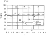
- the present inventors conducted further studies regarding Cr, Mo, Cu and Ni which are elements that influence SSC resistance. As a result, the present inventors discovered that excellent SSC resistance is obtained if, in a steel product having a chemical composition consisting of, in mass%, C: 0.030% or less, Si: 1.00% or less, Mn: 1.00% or less, P: 0.030% or less, S: 0.005% or less, Al: 0.0010 to 0.0100%, N: 0.0500% or less, Ni: 5.00 to 6.50%, Cr: 10.00 to 13.40%, Cu: 1.80 to 3.50%, Mo: 1.00 to 4.00%, V: 0.01 to 1.00%, Ti: 0.050 to 0.300%, Co: 0.300% or less and W: 0 to 1.50%, with the balance being Fe and impurities, a Cr content, a Mo content, a Cu content and a Ni content satisfy the following Formula (1): 11.5 ⁇ Cr + 2 ⁇ Mo + 2 ⁇ Cu ⁇ 1.5 ⁇ Ni ⁇ 14.
- F1 is defined as being equal to Cr+2Mo+2Cu-1.5Ni.
- FIG. 1 was obtained by means of examples that are described later.
- the symbol “ ⁇ ” in FIG. 1 indicates that SSC did not occur in an SSC resistance evaluation test in the examples that are described later.
- the symbol “ ⁇ ” in FIG. 1 indicates that SSC occurred in an SSC resistance evaluation test in the examples that are described later.
- F1 is less than 11.5 or when F1 is more than 14.3, SSC resistance decreases. Accordingly, F1 is from 11.5 to 14.3.
- the present inventors discovered that, in the steel product having the aforementioned chemical composition that satisfies Formula (1) and Formula (2), if the size of each intermetallic compound and the size of each Cr oxide in the microstructure is 5.0 ⁇ m 2 or less and the gross area fraction of the intermetallic compounds and the Cr oxides is 3.0% or less, the SSC resistance is further increased in the steel product having the aforementioned chemical composition that satisfies Formula (1) and Formula (2).
- the intermetallic compounds and the Cr oxides can be identified by structural observation using an extraction replica method.
- the total of the areas of the identified intermetallic compounds and the identified Cr oxides is taken as the gross area ( ⁇ m 2 ) of the intermetallic compounds and the Cr oxides.
- the proportion of the gross area of the intermetallic compounds and the Cr oxides with respect to the area of the overall observation region is taken as the gross area fraction (%) of intermetallic compounds and the Cr oxides.
- the microstructure contains martensite having an area fraction of 80% or more, the size of each intermetallic compounds and the size of each Cr oxides in the microstructure is 5.0 ⁇ m 2 or less and the gross area fraction of the intermetallic compounds and the Cr oxides in the microstructure is 3.0% or less, the strength of the steel product is adjustable to 724 to 860 MPa.
- the chemical composition of the aforementioned martensitic stainless steel product may contain W: 0.10 to 1.50%.
- Carbon (C) is unavoidably contained. That is, the C content is more than 0%. C increases the hardenability and raises the strength of the steel product. However, if the C content is too high, the strength of the steel product will be too high and the SSC resistance will decrease. Accordingly, the C content is 0.030% or less. It is preferable to make the C content as low as possible. However, if the C content is excessively reduced, the production cost increases. Therefore, when taking into consideration industrial production, a preferable lower limit of the C content is 0.0001%, and more preferably is 0.0005%. From the viewpoint of the strength of the steel product, a preferable lower limit of the C content is 0.002%, and more preferably is 0.005%. A preferable upper limit of the C content is 0.020%, and more preferably is 0.015%.
- Co Cobalt
- the Co content is more than 0%.
- the ductility and toughness decrease if the Co content is too high. Accordingly, the Co content is 0.300% or less.
- a preferable upper limit of the Co content is 0.270%, and more preferably is 0.250%.
- the Co content is as low as possible. However, if the Co content is excessively reduced, the production cost increases. Therefore, when taking into consideration industrial production, a preferable lower limit of the Co content is 0.0001%, and more preferably is 0.0005%.
- the chemical composition of the martensitic stainless steel product according to the present embodiment may further contain W in lieu of a part of Fe.
- Tungsten (W) is an optional element, and need not be contained. That is, the W content may be 0%. If W is contained, W stabilizes the passive film and improve corrosion resistance. However, if the W content is too high, W binds with C to form fine carbides. The fine carbides raise the strength of the steel product by fine precipitation hardening, and as a result, lower the SSC resistance. Accordingly, the W content is 0 to 1.50%. A preferable lower limit of the W content is 0.10%, and more preferably is 0.20%. A preferable upper limit of the W content is 1.00%, and more preferably is 0.50%.
- F1 is defined as being equal to Cr+2Mo+2Cu-1.5Ni.
- F1 is an index of the SSC resistance of the steel product having the aforementioned chemical composition. Referring to FIG. 1 , the SSC resistance decreases if F1 is less than 11.5. It is considered that the reason the SSC resistance decreases in this case is that the Ni content which reduces the diffusion coefficient of hydrogen in the steel is too high relative to the content of Cr, Mo and Cu that dissolve and increase the SSC resistance. On the other hand, when F1 is more than 14.3, the SSC resistance also decreases.
- F1 is from 11.5 to 14.3.
- a preferable lower limit of F1 is 11.7.
- a preferable upper limit of F1 is 14.0.
- F2 is less than 7.5
- the Ti content is too low relative to the C content. In that case, Ti is consumed to form nitrides such as TiN, and TiC cannot be formed sufficiently. Consequently, C is used for formation of VC, and the strength of the steel product is too high.
- F2 is 7.5 or more
- the Ti content is sufficiently high relative to the C content. As a result, Ti consumes C, and forms TiC with priority over VC. By this means, formation of VC can be suppressed. Therefore, the strength of the steel product can be kept from becoming too high. As a result, it can have excellent SSC resistance.
- the yield strength of the martensitic stainless steel of the present embodiment is 724 to 860 MPa. If the yield strength is less than 724 MPa, the strength will not be sufficient for steel product that can be applied to a highly corrosive environment. On the other hand, if the yield strength is more than 860 MPa, as illustrated in FIG. 1 , SSC resistance decreases in the steel product having the aforementioned chemical composition. Accordingly, the yield strength of the martensitic stainless steel of the present embodiment is 724 to 860 MPa. A preferable upper limit of the yield strength is 850 MPa, and more preferably is 840 MPa. A preferable lower limit of the yield strength is 730 MPa, and more preferably is 740 MPa. In the present description, the term "yield strength" means a 0.2% proof stress.
- intermetallic compound refers to a precipitate of an alloying element that precipitates after tempering.
- the intermetallic compounds are, for example, Laves phase such as Fe 2 Mo, sigma phase ( ⁇ phase), or chi phase ( ⁇ phase).
- size of an intermetallic compound refers to the area ( ⁇ m 2 ) of the intermetallic compound that is observed by a measurement that is described later.
- intermetallic compounds other than the Laves phase, the ⁇ phase, and the ⁇ phase are extremely small, so there is no problem ignoring them.
- Cr oxide refers to chromia (Cr 2 O 3 ).
- size of a Cr oxide refers to the area ( ⁇ m 2 ) of the Cr oxide that is observed by a measurement that is described later.
- each intermetallic compound and the size of each Cr oxide is 5.0 ⁇ m 2 or less, the intermetallic compounds and Cr oxides do not affect the SSC resistance.
- the size of the intermetallic compounds and the size of each Cr oxide is 1.0 ⁇ m 2 , 2.0 ⁇ m 2 , or even 5.0 ⁇ m 2 , the intermetallic compounds and Cr oxides do not affect the SSC resistance.
- the size of each intermetallic compound and Cr oxide is 5.0 ⁇ m 2 or less, if the gross area fraction of intermetallic compounds and Cr oxides is more than 3.0%, the intermetallic compounds and Cr oxides remarkably affect the SSC resistance.
- a test specimen having dimensions of 15 mm ⁇ 15 mm ⁇ 15 mm is extracted from a center position in the thickness direction of the martensitic stainless steel product.
- the term "center position in the thickness direction” refers to a center position with respect to the plate thickness
- the term "center position in the thickness direction” refers to a center position with respect to the wall thickness.
- One test specimen is extracted from a front end portion (top portion) and one test specimen is extracted from a rear end portion (bottom portion) in the longitudinal direction of the steel product.
- the term “front end portion” refers to, in a case where the steel product is divided equally into 10 sections in the longitudinal direction, the section at the front end, and the term “rear end portion” refers to the section at the rear end.
- the extraction replica film is a disk shape with a diameter of 3 mm.
- An arbitrary region of 10 ⁇ m 2 is observed at four places (four visual fields) at a magnification of 20,000 times on each extraction replica film using a TEM (transmission electron microscope). In other words, regions at eight places are observed for each steel product.
- a test specimen having dimensions of 15 mm ⁇ 15 mm ⁇ a thickness of 2 mm was extracted from each plate material.
- the volume ratio (%) of retained austenite was determined by the aforementioned X-ray diffraction method, and a value obtained when the volume ratio of retained austenite was subtracted from 100% was defined as the volume ratio (%) of martensite.
- a test specimen having dimensions of 15 mm ⁇ 15 mm ⁇ 15 mm was extracted from a center position of the thickness of each plate.
- One of the aforementioned test specimens was extracted from a front end portion (top portion) and one of the test specimens was extracted from a rear end portion (bottom portion) in the longitudinal direction of the plate.
- the term "front end portion” refers to, in a case where the steel product is divided equally into 10 sections in the longitudinal direction, the section at the front end, and the term “rear end portion” refers to the section at the rear end.
- Intermetallic compounds were identified based on contrast that was distinguished by means of backscattered electron images of the respective observation regions.
- the respective areas ( ⁇ m 2 ) of the identified intermetallic compounds and the respective Cr oxides were taken as the sizes of the respective intermetallic compounds and the respective Cr oxides.
- the total of the areas of the identified intermetallic compounds and the identified Cr oxides was taken as the gross area ( ⁇ m 2 ) of the intermetallic compounds and Cr oxides.
- the ratio of the gross area of the intermetallic compounds and the Cr oxides with respect to the gross area (80 ⁇ m 2 ) of the overall observation region was defined as the gross area fraction (%) of the intermetallic compounds and the Cr oxides.
- TM indicates that the volume ratio of martensite in the microstructure was 80% or more, the size of each intermetallic compound in the microstructure was 5.0 ⁇ m 2 or less, the size of each Cr oxide in the microstructure was 5.0 ⁇ m 2 or less and the gross area fraction of intermetallic compounds and Cr oxides in the microstructure was 3.0% or less.
- TM+I indicates that although the volume ratio of martensite in the microstructure was 80% or more, intermetallic compounds or Cr oxides having a size that was more than 5.0 ⁇ m 2 were present in the microstructure and/or the gross area fraction of intermetallic compounds and Cr oxides in the microstructure was more than 3.0%.
- the Ni content was high, the Cu content was low, and the tempering temperature was too low. Consequently, an intermetallic compound more than 5.0 ⁇ m 2 was observed and the gross area fraction of the intermetallic compounds and Cr oxides was more than 3.0%. As a result, the yield strength was 860 MPa or more and the SSC resistance was low.
Landscapes
- Chemical & Material Sciences (AREA)
- Engineering & Computer Science (AREA)
- Mechanical Engineering (AREA)
- Materials Engineering (AREA)
- Metallurgy (AREA)
- Organic Chemistry (AREA)
- Physics & Mathematics (AREA)
- Thermal Sciences (AREA)
- Crystallography & Structural Chemistry (AREA)
- Manufacturing & Machinery (AREA)
- Heat Treatment Of Sheet Steel (AREA)
- Heat Treatment Of Steel (AREA)
- Heat Treatment Of Articles (AREA)
Abstract
Description
- The present invention relates to a steel product, and more particularly to a martensitic stainless steel product which has mainly a martensitic microstructure.
- As low-corrosive wells (oil wells and gas wells) have been exhausted, the exploitation of wells with high corrosiveness is proceeding. Wells that have high corrosiveness are in environments which contain a large amount of corrosive substances, and the temperatures of wells that have high corrosiveness in such environments range from normal temperature to around 200°C, depending on the depth of the well. The corrosive substances are, for example, corrosive gases such as hydrogen sulfide and carbon dioxide gas. In the present description, a well environment containing carbon dioxide gas, and with high corrosiveness in which the hydrogen sulfide partial pressure is 0.1 bar or more is referred to as a "highly corrosive environment".
- It is known that chromium (Cr) is effective for improving the carbonic-acid gas corrosion resistance of steel. Therefore, in an environment that contains a large amount of carbon dioxide gas, martensitic stainless steel containing around 13 mass% Cr (hereunder, referred to as "13Cr steel") as represented by API L80-13Cr steel (conventional 13Cr steel) or super 13Cr steel or the like, or duplex stainless steel to which a large amount of Cr is added or the like are used in accordance with the partial pressure or temperature of the carbon dioxide gas.
- However, hydrogen sulfide causes sulfide stress cracking (hereunder, referred to as "SSC") in steel pipes for oil well made of 13Cr steel with a high strength of, for example, 724 MPa or more. 13Cr steel that has a high strength of 724 MPa or more has a higher susceptibility to SSC compared to low-alloy steel, and in the 13 Cr steel, SSC occurs even at a comparatively low hydrogen sulfide partial pressure (for example, less than 0.1 atm). Therefore, 13Cr steel is not suitable for use in the above-described highly corrosive environments containing carbon dioxide gas and hydrogen sulfide. Further, duplex stainless steel is expensive in comparison to 13Cr steel. Consequently, there is a required for a steel pipe for oil well casing, tubing and drilling that has a high yield strength of 724 MPa or more and high SSC resistance that can be used in highly corrosive environments.
- Steels having excellent SSC resistance are proposed in Japanese Patent Application Publication No.
10-001755 10-503809 2003-003243 WO 2004/057050 (Patent Literature 4), Japanese Patent Application Publication No.2000-192196 11-310855 08-246107 2012-136742 - A martensitic stainless steel disclosed in Patent Literature 1 consists of, in mass%, C: 0.005 to 0.05%, Si: 0.05 to 0.5%, Mn: 0.1 to 1.0%, P: 0.025% or less, S: 0.015% or less, Cr: 10 to 15%, Ni: 4.0 to 9.0%, Cu: 0.5 to 3%, Mo: 1.0 to 3%, Al: 0.005 to 0.2% and N: 0.005% to 0.1%, with the balance being Fe and unavoidable impurities. The steel satisfies the relation 40C+34N+Ni+0.3Cu-1.1Cr-1.8Mo ≥ -10, and consists of a tempered martensite phase, a martensite phase and a retained austenite phase. The total of the fractions of the tempered martensite phase and martensite phase is 60% or more to 90% or less, and the remainder is the retained austenite phase.
- A martensitic stainless steel disclosed in Patent Literature 2 consists of, in mass%, C: 0.005 to 0.05%, Si ≤ 0.50%, Mn: 0.1 to 1.0%, P ≤ 0.03%, S ≤ 0.005%, Mo: 1.0 to 3.0%, Cu: 1.0 to 4.0%, Ni: 5 to 8% and Al ≤ 0.06%. The steel satisfies the relations Cr+1.6Mo ≥ 13 and 40C+34N+Ni+0.3Cu-1.1Cr-1.8Mo ≥ -10.5. The balance is substantially of Fe and the microstructure is a tempered martensite.
- A martensitic stainless steel disclosed in Patent Literature 3 consists of, in mass%, C: 0.001 to 0.04%, Si: 0.5% or less, Mn: 0.1 to 3.0%, P: 0.04% or less, S: 0.01% or less, Cr: 10 to 15%, Ni: 0.7 to 8%, Mo: 1.5 to 5.0%, Al: 0.001 to 0.10% and N: 0.07% or less, with the balance being Fe and impurities. The steel also satisfies the relation Mo ≥ 1.5-0.89Si+32.2C. The metal microstructure mainly consists of tempered martensite, carbides that precipitated during tempering, and Laves phase-based intermetallic compounds that finely precipitated during tempering. The martensitic stainless steel of Patent Literature 3 has high strength with a yield stress of 860 MPa or more.
- A martensitic stainless steel disclosed in Patent Literature 4 consists of, in mass%, C: 0.005 to 0.04%, Si: 0.5% or less, Mn: 0.1 to 3.0%, P: 0.04% or less, S: 0.01% or less, Cr: 10 to 15%, Ni: 4.0 to 8%, Mo: 2.8 to 5.0%, Al: 0.001 to 0.10% and N: 0.07% or less, with the balance being Fe and impurities. The steel also satisfies the relation Mo ≥ 2.3-0.89Si+32.2C. The metal microstructure mainly consists of tempered martensite, carbides that precipitated during tempering, and Laves-phase or σ-phase intermetallic compounds or the like that finely precipitated during tempering. The martensitic stainless steel of Patent Literature 4 has high strength with a yield stress of 860 MPa or more.
- A martensitic stainless steel disclosed in Patent Literature 5 consists of in weight%, C: 0.001 to 0.05%, Si: 0.05 to 1%, Mn: 0.05 to 2%, P: 0.025% or less, S: 0.01% or less, Cr: 9 to 14%, Mo: 3.1 to 7%, Ni: 1 to 8%, Co: 0.5 to 7%, sol. Al: 0.001 to 0.1%, N: 0.05% or less, O (oxygen): 0.01% or less, Cu: 0 to 5% and W: 0 to 5%, with the balance being Fe and unavoidable impurities.
- A martensitic stainless steel disclosed in Patent Literature 6 contains C: 0.05% or less and Cr: 7 to 15%. Further, a Cu content in a dissolved state is 0.25 to 5%.
- A martensitic stainless steel disclosed in Patent Literature 7 consists of, in weight%, C: 0.005% to 0.05%, Si: 0.05% to 0.5%, Mn: 0.1% to 1.0%, P: 0.025% or less, S: 0.015% or less, Cr: 12 to 15%, Ni: 4.5% to 9.0%, Cu: 1% to 3%, Mo: 2% to 3%, W: 0.1% to 3%, Al: 0.005 to 0.2% and N: 0.005% to 0.1%, with the balance being Fe and unavoidable impurities. The steel satisfies the relation 40C+34N+Ni+0.3Cu+Co-1.1Cr-1.8Mo-0.9W ≥ -10.
- A martensitic stainless steel seamless pipe disclosed in Patent Literature 8 consists of, in mass%, C: 0.01% or less, Si: 0.5% or less, Mn: 0.1 to 2.0%, P: 0.03% or less, S: 0.005% or less, Cr: 14.0 to 15.5%, Ni: 5.5 to 7.0%, Mo: 2.0 to 3.5%, Cu: 0.3 to 3.5%, V: 0.20% or less, Al: 0.05% or less and N: 0.06% or less, with the balance being Fe and unavoidable impurities. The martensitic stainless steel seamless pipe disclosed in Patent Literature 8 has a strength of 655 to 862 MPa as the yield strength and a yield ratio of 0.90 or more.
-
- Patent Literature 1: Japanese Patent Application Publication No.
10-001755 - Patent Literature 2: Japanese Patent Application Publication No.
10-503809 - Patent Literature 3: Japanese Patent Application Publication No.
2003-003243 - Patent Literature 4: International Application Publication No.
WO 2004/057050 - Patent Literature 5: Japanese Patent Application Publication No.
2000-192196 - Patent Literature 6: Japanese Patent Application Publication No.
11-310855 - Patent Literature 7: Japanese Patent Application Publication No.
08-246107 - Patent Literature 8: Japanese Patent Application Publication No.
2012-136742 - However, the yield strength of the martensitic stainless steels described in Patent Literature 1 and Patent Literature 2 sometimes becomes too high. In such a case, the SSC resistance is low.
- The martensitic stainless steels described in Patent Literature 3 and Patent Literature 4 are 13Cr steel, and fine carbides and intermetallic compounds are caused to precipitate in the steel. The observed intermetallic compounds and the like are not only fine compounds, and some of the intermetallic compounds and the like that are present are coarse to a certain extent. Consequently, the yield strength of the martensitic stainless steel is a strength of 125 ksi grade (yield strength is 860 MPa or more). Therefore, the SSC resistance is low in some cases.
- In the martensitic stainless steel described in Patent Literature 5, Mo content and Co content are high. Consequently, in some cases the strength is too high and the SSC resistance decreases. In addition, if the Mo content is too high, the stability of the martensitic microstructure decreases in some cases.
- The martensitic stainless steel disclosed in Patent Literature 6 is quenched martensitic steel on which tempering is not performed. Therefore, in some cases the strength is too high and the SSC resistance is low.
- The martensitic stainless steel disclosed in Patent Literature 7 contains Cu and W and does not contain Ti. Therefore, the yield strength of the martensitic stainless steel may be too high in some cases. In such a case, the SSC resistance becomes lower.
- The martensitic stainless steel seamless pipe disclosed in Patent Literature 8 contains 14.0 to 15.5 mass% of Cr. Therefore, in some cases the steel has a ferritic phase. In such a case, the strength may be insufficient.
- An objective of the present disclosure is to provide a martensitic stainless steel product having a yield strength of 724 MPa or more and having excellent SSC resistance.
- A martensitic stainless steel product according to the present disclosure has a chemical composition consisting of, in mass%, C: 0.030% or less, Si: 1.00% or less, Mn: 1.00% or less, P: 0.030% or less, S: 0.005% or less, Al: 0.0010 to 0.0100%, N: 0.0500% or less, Ni: 5.00 to 6.50%, Cr: 10.00 to 13.40%, Cu: 1.80 to 3.50%, Mo: 1.00 to 4.00%, V: 0.01 to 1.00%, Ti: 0.050 to 0.300%, Co: 0.300% or less and W: 0 to 1.50%, with the balance being Fe and impurities, and satisfying Formula (1) and Formula (2), and the yield strength of 724 to 860 MPa, and the microstructure containing martensite having a volume ratio of 80% or more. A size of each intermetallic compound and a size of each Cr oxide in the microstructure is not more than 5.0 µm2, and a gross area fraction of the intermetallic compounds and Cr oxides is 3.0 % or less.


- A martensitic stainless steel product according to the present embodiment has the yield strength of 724 MPa or more, and excellent SSC resistance.
-
- [
FIG. 1] FIG. 1 is a view illustrating the relation between F1 = Cr+2Mo+2Cu-1.5Ni, a yield strength YS (MPa) and SSC resistance. - [
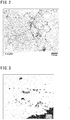
FIG. 2] FIG. 2 is a TEM (transmission electron microscope) image obtained when the metal microstructure of steel of Test No. 3 in the Examples according to the present embodiment was observed. - [
FIG. 3] FIG. 3 is an SEM (scanning electron microscope) image obtained when the metal microstructure of steel of Test No. 9 in the Examples was observed. - The present inventors conducted investigations and studies regarding the SSC resistance of martensitic stainless steel product, and obtained the following findings.
- It is generally known that Cr, Mo, Cu and Ni are effective for raising the SSC resistance of steel. Specifically, it is considered that Cr, Mo and Cu dissolve to raise the SSC resistance. On the other hand, it is considered that Ni raises the SSC resistance by strengthening a film on the surface of the steel product to thereby reduce the amount of hydrogen that penetrates into the steel product (hydrogen permeation amount).
- However, as the result of studies, the present inventors found for the first time that in a highly corrosive environment such as described above, strengthening a film by Ni decreases a hydrogen diffusion coefficient in the steel. If the hydrogen diffusion coefficient in the steel decreases, hydrogen is liable to stay in the steel product. Consequently, the SSC resistance of the steel product decreases.
- Therefore, the present inventors conducted further studies regarding Cr, Mo, Cu and Ni which are elements that influence SSC resistance. As a result, the present inventors discovered that excellent SSC resistance is obtained if, in a steel product having a chemical composition consisting of, in mass%, C: 0.030% or less, Si: 1.00% or less, Mn: 1.00% or less, P: 0.030% or less, S: 0.005% or less, Al: 0.0010 to 0.0100%, N: 0.0500% or less, Ni: 5.00 to 6.50%, Cr: 10.00 to 13.40%, Cu: 1.80 to 3.50%, Mo: 1.00 to 4.00%, V: 0.01 to 1.00%, Ti: 0.050 to 0.300%, Co: 0.300% or less and W: 0 to 1.50%, with the balance being Fe and impurities, a Cr content, a Mo content, a Cu content and a Ni content satisfy the following Formula (1):

- F1 is defined as being equal to Cr+2Mo+2Cu-1.5Ni.
FIG. 1 is a view illustrating the relation between F1 = Cr+2Mo+2Cu-1.5Ni, a yield strength YS (MPa) and SSC resistance.FIG. 1 was obtained by means of examples that are described later. The symbol "○" inFIG. 1 indicates that SSC did not occur in an SSC resistance evaluation test in the examples that are described later. The symbol "×" inFIG. 1 indicates that SSC occurred in an SSC resistance evaluation test in the examples that are described later. When F1 is less than 11.5 or when F1 is more than 14.3, SSC resistance decreases. Accordingly, F1 is from 11.5 to 14.3. - The SSC resistance also depends on the strength of the steel product. Specifically, the higher the strength of the steel product is, the more the SSC resistance decreases. Therefore, the present inventors also conducted studies regarding the relation between the SSC resistance and the strength of a steel product having a chemical composition consisting of, in mass%, C: 0.030% or less, Si: 1.00% or less, Mn: 1.00% or less, P: 0.030% or less, S: 0.005% or less, Al: 0.0010 to 0.0100%, N: 0.0500% or less, Ni: 5.00 to 6.50%, Cr: 10.00 to 13.40%, Cu: 1.80 to 3.50%, Mo: 1.00 to 4.00%, V: 0.01 to 1.00%, Ti: 0.050 to 0.300%, Co: 0.300% or less, and W: 0 to 1.50%, with the balance being Fe and impurities, and that satisfies Formula (1). As a result, in the steel product having the above-described chemical composition that satisfies Formula (1), the present inventors discovered that an optimal yield strength of a steel product exists in order for the steel product to have excellent SSC resistance while also obtaining the necessary strength. Specifically, if the yield strength of the steel product having the above-described chemical composition that satisfies Formula (1) is from 724 to 860 MPa, the necessary strength can be obtained and the SSC resistance is raised.
- Referring to
FIG. 1 , if F1 is in the range from 11.5 to 14.3 and YS is 860 MPa or less, excellent SSC resistance is obtained. Therefore, in the present embodiment, the yield strength of the steel product is from 724 to 860 MPa. - As described above, the chemical composition of the steel product of the present embodiment contains, in mass%, 1.00 to 4.00% of Mo, 1.80 to 3.50% of Cu and 0.01 to 1.00% of V. These elements dissolve and raise the SSC resistance. However, Mo, Cu and V also raise the strength of the steel product. As described above, if the strength of the steel product having the aforementioned chemical composition that satisfies Formula (1) is too high, SSC resistance decreases.
- Therefore, the present inventors conducted additional studies regarding methods for regulating the strength of the steel product. As a result, the present inventors discovered that by containing Ti and adjusting the Ti content relative to the C content, excessive strengthening can be suppressed.
- The reason is as follows. Among the aforementioned elements Mo, Cu and V that raise the strength of steel product, V forms carbides (VC) and thereby raises the strength of the steel product. Similarly to V, Ti binds with C in the steel to form carbides. Consequently, if Ti binds with C, the amount of C for forming VC will be insufficient because of the consumption of C by Ti. As a result, VC can be suppressed.
- Generally, the affinity of Ti for C in steel is equal to the affinity of V for C. Consequently, in a material containing V and Ti, VC and TiC precipitate simultaneously. Therefore, the ratio of the Ti content (mass%) with respect to the C content (mass%) is increased to thereby adjust the chemical composition so that TiC precipitates with priority over VC. In other words, the Ti content (mass%) and C content (mass%) satisfy Formula (2).

- F2 is defined as being equal to Ti/C. When F2 is less than 7.5, Ti is consumed to form nitrides such as TiN, and TiC cannot be sufficiently formed. Consequently, C is used for formation of VC in the steel, and the strength of the steel product becomes too high. If F2 is 7.5 or more, the Ti content is sufficiently high relative to the C content. Therefore, TiC precipitates with priority over VC. Consequently, formation of VC is suppressed. As a result, the yield strength of the steel product having the chemical composition that satisfies Formula (1) can be suppressed to 860 MPa or less, and excellent SSC resistance is obtained.
- It is known that if coarse intermetallic compounds or coarse Cr oxides are present in the microstructure, the coarse intermetallic compounds and coarse Cr oxides become starting points for SSC, and the SSC resistance decreases. Therefore, conventionally, coarsening of Cr oxides have been suppressed and intermetallic compounds have been caused to finely precipitate to thereby raise the SSC resistance. That is, it has been thought heretofore that fine Cr oxides and fine intermetallic compounds do not affect SSC resistance. However, the present inventors newly found that in the steel product having the aforementioned chemical composition that satisfies Formula (1) and Formula (2), fine Cr oxides and fine intermetallic compounds also lower SSC resistance. As the result of further studies, the present inventors discovered that, in the steel product having the aforementioned chemical composition that satisfies Formula (1) and Formula (2), if the size of each intermetallic compound and the size of each Cr oxide in the microstructure is 5.0 µm2 or less and the gross area fraction of the intermetallic compounds and the Cr oxides is 3.0% or less, the SSC resistance is further increased in the steel product having the aforementioned chemical composition that satisfies Formula (1) and Formula (2).
- In the present description, the term "intermetallic compound" refers to a precipitate of an alloying element that precipitates after tempering. The intermetallic compounds are, for example, Laves phase such as Fe2Mo sigma phase (σ phase) or chi phase (χ phase). The σ phase is FeCr and χ phase is Fe36Cr12Mo10. In the present description, the term "Cr oxide" refers to chromia (Cr2O3).
- The intermetallic compounds and the Cr oxides can be identified by structural observation using an extraction replica method. The total of the areas of the identified intermetallic compounds and the identified Cr oxides is taken as the gross area (µm2) of the intermetallic compounds and the Cr oxides. The proportion of the gross area of the intermetallic compounds and the Cr oxides with respect to the area of the overall observation region is taken as the gross area fraction (%) of intermetallic compounds and the Cr oxides.
- If the intermetallic compound having an area that is more than 5.0 µm2 or the Cr oxide having an area that is more than 5.0 µm2 are present in the metal microstructure, such coarse intermetallic compounds or coarse Cr oxides become starting points for SSC, and the SSC resistance decreases. Accordingly, the size of each intermetallic compound in the microstructure is 5.0 µm2 or less, and the size of each Cr oxide in the microstructure is 5.0 µm2 or less. Specifically, in the present embodiment, intermetallic compounds having a size (area) that is more than 5.0 µm2 and Cr oxides having a size (area) that is more than 5.0 µm2 are not observed when a microstructure observation is conducted as described later.
- In addition, if the gross area fraction of intermetallic compounds and Cr oxides in the metal microstructure is more than 3.0%, the SSC resistance decreases because too many intermetallic compounds and Cr oxides having a size of 5.0 µm2 or less are present. Accordingly, the gross area fraction of intermetallic compounds and Cr oxides in the microstructure is 3.0% or less.
- If the chemical composition of the steel product satisfies Formula (1) and Formula (2), the microstructure contains martensite having an area fraction of 80% or more, the size of each intermetallic compounds and the size of each Cr oxides in the microstructure is 5.0 µm2 or less and the gross area fraction of the intermetallic compounds and the Cr oxides in the microstructure is 3.0% or less, the strength of the steel product is adjustable to 724 to 860 MPa.
- A martensitic stainless steel product according to the present embodiment, which has been completed based on the above findings, has a chemical composition that consists of, in mass%, C: 0.030% or less, Si: 1.00% or less, Mn: 1.00% or less, P: 0.030% or less, S: 0.005% or less, Al: 0.0010 to 0.0100%, N: 0.0500% or less, Ni: 5.00 to 6.50%, Cr: 10.00 to 13.40%, Cu: 1.80 to 3.50%, Mo: 1.00 to 4.00%, V: 0.01 to 1.00%, Ti: 0.050 to 0.300%, Co: 0.300% or less, W: 0 to 1.50%, with the balance being Fe and impurities, and that satisfies Formula (1) and Formula (2). The yield strength of the aforementioned martensitic stainless steel product is 724 to 860 MPa. The microstructure of the aforementioned martensitic stainless steel product contains martensite having a volume ratio of 80% or more. The size of each intermetallic compound and the size of each Cr oxide in the microstructure is 5.0 µm2 or less, and the gross area fraction of the intermetallic compounds and the Cr oxides is 3.0% or less.


- The chemical composition of the aforementioned martensitic stainless steel product may contain W: 0.10 to 1.50%.
- The aforementioned martensitic stainless steel product is, for example, a seamless steel pipe for oil well casing, tubing and drilling.
- In the present description, the term "steel pipe for oil well casing, tubing and drilling" means, for example, a steel pipe for oil well casing, tubing and drilling that is described in the definition column of No. 3514 in JIS G 0203 (2009). Specifically, the term "steel pipe for oil well casing, tubing and drilling" is a generic name for casing, tubing and drill pipes that are used for drilling oil wells or gas wells, and for extracting crude oil and natural gas and the like. The term "seamless steel pipe for oil well casing, tubing and drilling" means that the steel pipe for oil well casing, tubing and drilling is a seamless steel pipe.
- The martensitic stainless steel product of the present embodiment is described in detail hereunder. The symbol"%" in relation to an element means "mass%" unless specifically stated otherwise.
- The chemical composition of the martensitic stainless steel product of the present embodiment contains the following elements.
- Carbon (C) is unavoidably contained. That is, the C content is more than 0%. C increases the hardenability and raises the strength of the steel product. However, if the C content is too high, the strength of the steel product will be too high and the SSC resistance will decrease. Accordingly, the C content is 0.030% or less. It is preferable to make the C content as low as possible. However, if the C content is excessively reduced, the production cost increases. Therefore, when taking into consideration industrial production, a preferable lower limit of the C content is 0.0001%, and more preferably is 0.0005%. From the viewpoint of the strength of the steel product, a preferable lower limit of the C content is 0.002%, and more preferably is 0.005%. A preferable upper limit of the C content is 0.020%, and more preferably is 0.015%.
- Silicon (Si) is unavoidably contained. That is, the Si content is more than 0%. Si deoxidizes the steel. However, if the Si content is too high, the effect is saturated. Accordingly, the Si content is 1.00% or less. A preferable lower limit of the Si content is 0.05%, and more preferably is 0.10%. A preferable upper limit of the Si content is 0.70%, and more preferably is 0.50%.
- Manganese (Mn) is unavoidably contained. That is, the Mn content is more than 0%. Mn raises the hardenability of the steel. However, if the Mn content is too high, the Mn segregates at the grain boundary together with impurity elements such as P and S. In such a case, the SSC resistance decreases. Accordingly, the Mn content is 1.00% or less. A preferable lower limit of the Mn content is 0.15%, and more preferably is 0.20%. A preferable upper limit of the Mn content is 0.80%, and more preferably is 0.50%.
- Phosphorous (P) is an impurity that is unavoidably contained. That is, the P content is more than 0%. P segregates at the crystal grain boundary and decreases the SSC resistance of the steel. Accordingly, the P content is 0.030% or less. A preferable upper limit of the P content is 0.025%, and more preferably is 0.020%. Preferably, the P content is as low as possible. However, if the P content is excessively reduced, the production cost increases. Therefore, when taking into consideration industrial production, a preferable lower limit of the P content is 0.0001%, and more preferably is 0.0005%.
- Sulfur (S) is an impurity that is unavoidably contained. That is, the S content is more than 0%. Similarly to P, S also segregates at the crystal grain boundary and decreases the SSC resistance of the steel. Accordingly, the S content is 0.005% or less. A preferable upper limit of the S content is 0.003%, and more preferably is 0.001%. Preferably, the S content is as low as possible. However, if the P content is excessively reduced, the production cost increases. Therefore, when taking into consideration industrial production, a preferable lower limit of the S content is 0.0001%, and more preferably is 0.0005%.
- Aluminum (Al) deoxidizes the steel. If the Al content is low, this effect is not obtained. On the other hand, if the Al content is too high, the effect is saturated. Accordingly, the Al content is from 0.0010 to 0.0100%. A preferable lower limit of the Al content is 0.0020%, and more preferably is 0.0030%. A preferable upper limit of the Al content is 0.0070%, and more preferably is 0.0050%. In the present description, the term "Al content" means the content of sol. Al (acid-soluble Al).
- Nitrogen (N) is an impurity that is unavoidably contained. That is, the N content is more than 0%. N forms nitrides and reduces the SSC resistance. Accordingly, the N content is 0.0500% or less. A preferable upper limit of the N content is 0.0300% or less, and more preferably is 0.0200% or less. Preferably, the N content is as low as possible. However, if the N content is excessively reduced, the production cost increases. Therefore, when taking into consideration industrial production, a preferable lower limit of the N content is 0.0001%, and more preferably is 0.0005%.
- Nickel (Ni) is an austenite forming element, and martensitizes the microstructure after quenching. If the Ni content is too low, the microstructure after tempering will contain a large amount of ferrite. On the other hand, if the Ni content is too high, in a highly corrosive well, the Ni will cause the hydrogen diffusion coefficient in the steel to decrease due to film strengthening. If the hydrogen diffusion coefficient in the steel decreases, the SSC resistance will decrease. Therefore, the Ni content is from 5.00 to 6.50%. A preferable lower limit of the Ni content is 5.20%, and more preferably is 5.30%. A preferable upper limit of the Ni content is 6.30%, and more preferably is 6.20%.
- Chromium (Cr) raises the carbon dioxide gas corrosion resistance of the steel at a high temperature. If the Cr content is too low, this effect is not obtained. If the Cr content is 10.00% or more, the steel exhibits excellent carbon dioxide gas corrosion resistance at high temperatures. On the other hand, if the Cr content is too high, coarse intermetallic compounds and coarse Cr oxides are formed and the SSC resistance decreases. Accordingly, the Cr content is from 10.00 to 13.40%. A preferable lower limit of the Cr content is 11.00%, and more preferably is 11.50%. A preferable upper limit of the Cr content is 13.30%, and more preferably is 13.00%.
- Copper (Cu) is an austenite forming element, similarly to Ni, and martensitizes the microstructure after quenching. Cu also dissolve in the steel and raises the SSC resistance. If the Cu content is too low, these effects are not obtained. On the other hand, if the Cu content is too high, hot workability decreases. Therefore, the Cu content is from 1.80 to 3.50%. A preferable lower limit of the Cu content is 1.90%, and more preferably is 1.95%. A preferable upper limit of the Cu content is 3.30%, and more preferably is 3.10%.
- Molybdenum (Mo) raises the SSC resistance and the strength of the steel. If the Mo content is too low, these effects are not obtained. On the other hand, Mo is a ferrite forming element. Therefore, if the Mo content is too high it becomes difficult for austenite to stabilize, and it is difficult to stably obtain a martensitic microstructure. Accordingly, the Mo content is from 1.00 to 4.00%. A preferable lower limit of the Mo content is 1.20%, and more preferably is 1.50%, and more preferably is 1.80%. A preferable upper limit of the Mo content is 3.50%, and more preferably is 3.00%, and more preferably is 2.70%.
- Vanadium (V) dissolves in the steel and suppresses intergranular cracking of the steel in a highly corrosive environment. If the V content is too low, this effect is not obtained. On the other hand, V raises the hardenability of the steel, and easily forms carbides. Therefore, if the V content is too high, the strength of the steel product increases and the SSC resistance decreases. Accordingly, the V content is 0.01 to 1.00%. A preferable lower limit of the V content is 0.02%, and more preferably is 0.03%. A preferable upper limit of the V content is 0.80%, and more preferably is 0.70%.
- Titanium (Ti) binds with C to form carbides. By this means, C for forming VC is consumed by Ti, and formation of VC can be suppressed. Therefore, the SSC resistance of the steel increases. This effect is not obtained if the Ti content is too low. On the other hand, if the Ti content is too high, the aforementioned effect is saturated and, in addition, the formation of ferrite is promoted. Accordingly, the Ti content is from 0.050 to 0.300%. A preferable lower limit of the Ti content is 0.060%, and more preferably is 0.070%, and more preferably is 0.080%. A preferable upper limit of the Ti content is 0.250%, and more preferably is 0.200%, and more preferably is 0.150%.
- Cobalt (Co) is an impurity that is unavoidably contained. That is, the Co content is more than 0%. The ductility and toughness decrease if the Co content is too high. Accordingly, the Co content is 0.300% or less. A preferable upper limit of the Co content is 0.270%, and more preferably is 0.250%. Preferably, the Co content is as low as possible. However, if the Co content is excessively reduced, the production cost increases. Therefore, when taking into consideration industrial production, a preferable lower limit of the Co content is 0.0001%, and more preferably is 0.0005%.
- The balance of the martensitic stainless steel product according to the present embodiment is Fe and impurities. Here, the term "impurities" refers to elements which, during industrial production of the steel, are mixed in from ore or scrap used as a raw material, or from the production environment or the like.
- The chemical composition of the martensitic stainless steel product according to the present embodiment may further contain W in lieu of a part of Fe.
- Tungsten (W) is an optional element, and need not be contained. That is, the W content may be 0%. If W is contained, W stabilizes the passive film and improve corrosion resistance. However, if the W content is too high, W binds with C to form fine carbides. The fine carbides raise the strength of the steel product by fine precipitation hardening, and as a result, lower the SSC resistance. Accordingly, the W content is 0 to 1.50%. A preferable lower limit of the W content is 0.10%, and more preferably is 0.20%. A preferable upper limit of the W content is 1.00%, and more preferably is 0.50%.
- The aforementioned chemical composition also satisfies Formula (1):

- F1 is defined as being equal to Cr+2Mo+2Cu-1.5Ni. F1 is an index of the SSC resistance of the steel product having the aforementioned chemical composition. Referring to
FIG. 1 , the SSC resistance decreases if F1 is less than 11.5. It is considered that the reason the SSC resistance decreases in this case is that the Ni content which reduces the diffusion coefficient of hydrogen in the steel is too high relative to the content of Cr, Mo and Cu that dissolve and increase the SSC resistance. On the other hand, when F1 is more than 14.3, the SSC resistance also decreases. It is considered that the reason the SSC resistance decreases in this case is that the Ni content which forms a film on the surface and suppresses the infiltration of hydrogen is too low relative to the content of Cr, Mo and Cu that increase the SSC resistance, and consequently the amount of hydrogen that infiltrates into the steel increases, and as a result the SSC resistance decreases. Therefore, F1 is from 11.5 to 14.3. A preferable lower limit of F1 is 11.7. A preferable upper limit of F1 is 14.0. - Note that, the value of F1 is a value obtained by rounding off to two decimal places.
- The aforementioned chemical composition satisfies Formula (1) and also satisfies Formula (2):

- F2 is defined as being equal to Ti/C. F2 is an index of suppression of VC precipitation by Ti, that is, an index of the strength of the steel product. As described above, in general, in a material containing V and Ti, VC and TiC precipitate simultaneously. Therefore, in the chemical composition that satisfies Formula (1), the ratio of the Ti content (mass%) with respect to the C content (mass%) is raised to thereby adjust the chemical composition so that TiC precipitates with priority over VC. By this means, C is consumed by Ti, and binding of C with V to form VC is suppressed.
- If F2 is less than 7.5, the Ti content is too low relative to the C content. In that case, Ti is consumed to form nitrides such as TiN, and TiC cannot be formed sufficiently. Consequently, C is used for formation of VC, and the strength of the steel product is too high. When F2 is 7.5 or more, the Ti content is sufficiently high relative to the C content. As a result, Ti consumes C, and forms TiC with priority over VC. By this means, formation of VC can be suppressed. Therefore, the strength of the steel product can be kept from becoming too high. As a result, it can have excellent SSC resistance.
- Note that, the value of F2 is a value obtained by rounding off to two decimal places.
- Martensite is the main constituent of the microstructure of the above described martensitic stainless steel product. In this case, the term "martensite" also includes tempered martensite. The phrase "martensite is the main microstructure" means that, in the microstructure, the volume ratio of martensite is 80% or more. The balance of the microstructure is retained austenite. The volume ratio of retained austenite is 0 to 20%. Preferably, the volume ratio of retained austenite is as low as possible. A preferable lower limit of the volume ratio of martensite in the microstructure is 85%, and more preferably is 90%. Further preferably, the metal microstructure is a martensite single-phase structure.
- In the aforementioned microstructure, a retained austenite that is a small amount does not result in a significant decrease in strength, and noticeably raises the toughness of the steel. However, if the volume ratio of retained austenite is too high, the strength of the steel noticeably decreases. Accordingly, the volume ratio of retained austenite is 0 to 20%. From the viewpoint of ensuring strength, a more preferable volume ratio of retained austenite is 0 to 10%. As described above, the microstructure of the martensitic stainless steel product of the present embodiment may be a martensite single-phase structure. Accordingly, in such case, the volume ratio of retained austenite will be 0%. On the other hand, in a case where even a small amount of retained austenite is present, the volume ratio of retained austenite is from more than 0 to not more than 20%, and more preferably is from more than 0 to 10%.
- The volume ratio (vol%) of martensite is determined by subtracting the volume ratio (vol%) of retained austenite that is determined by a method described hereunder from 100%.
- The volume ratio of retained austenite is determined by an X-ray diffraction method. Specifically, a sample is extracted from an arbitrary position of the martensitic stainless steel product. The size of the sample is set as 15 mm × 15 mm × thickness of 2 mm. Using the sample, the respective X-ray intensities of the (200) plane and (211) plane of the ferrite (α phase), and the (200) plane, (220) plane and (311) plane of the retained austenite (γ phase) are measured. The integrated intensity of each plane is then calculated. After calculating the integrated intensities, the volume ratio Vγ (%) is calculated using Formula (A) for each combination of the respective planes of the α phase with the respective planes of the γ phase (total of six combinations). Further, the average value of the six combinations of the volume ratio Vγ is defined as the volume ratio (%) of retained austenite.

- A value obtained by subtracting the volume ratio of retained austenite obtained by the above method from 100% is taken as the volume ratio (vol%) of martensite in the microstructure. Note that, the volume ratio of inclusions and precipitates such as intermetallic compounds that are described below is excluded from the "100%" of the volume ratio of the microstructure that is mentioned here.
- The yield strength of the martensitic stainless steel of the present embodiment is 724 to 860 MPa. If the yield strength is less than 724 MPa, the strength will not be sufficient for steel product that can be applied to a highly corrosive environment. On the other hand, if the yield strength is more than 860 MPa, as illustrated in
FIG. 1 , SSC resistance decreases in the steel product having the aforementioned chemical composition. Accordingly, the yield strength of the martensitic stainless steel of the present embodiment is 724 to 860 MPa. A preferable upper limit of the yield strength is 850 MPa, and more preferably is 840 MPa. A preferable lower limit of the yield strength is 730 MPa, and more preferably is 740 MPa. In the present description, the term "yield strength" means a 0.2% proof stress. - In the martensitic stainless steel product of the present embodiment, the size of each intermetallic compound and the size of each Cr oxide in the microstructure is 5.0 µm2 or less, and the gross area fraction of intermetallic compounds and Cr oxides in the microstructure is 3.0% or less. In other words, in the present embodiment, intermetallic compounds having a size that is greater than 5.0 µm2 and Cr oxides having a size that is greater than 5.0 µm2 are not observed.
- Here, the term "intermetallic compound" refers to a precipitate of an alloying element that precipitates after tempering. The intermetallic compounds are, for example, Laves phase such as Fe2Mo, sigma phase (σ phase), or chi phase (χ phase). Further, the term "size of an intermetallic compound" refers to the area (µm2) of the intermetallic compound that is observed by a measurement that is described later. In the case of the chemical composition of the above embodiment, intermetallic compounds other than the Laves phase, the σ phase, and the χ phase are extremely small, so there is no problem ignoring them. In the present description, the term "Cr oxide" refers to chromia (Cr2O3). the term "size of a Cr oxide" refers to the area (µm2) of the Cr oxide that is observed by a measurement that is described later.
- Even when a steel product has a chemical composition that satisfies Formula (1) and Formula (2), and is a steel product in which the volume ratio of martensite is 80% or more and which has a yield strength of 724 to 860 MPa, if intermetallic compounds of a size that is more than 5.0 µm2 or Cr oxides of a size that is more than 5.0 µm2 are present among intermetallic compounds and Cr oxides in the microstructure, or the gross area fraction of intermetallic compounds and Cr oxides is more than 3.0%, SSC that is attributable to the intermetallic compounds and Cr oxides arises, and the SSC resistance decreases. As described above, in a steel product that has a chemical composition that satisfies Formula (1) and Formula (2), and in which the volume ratio of martensite is 80% or more and the yield strength is 724 to 860 MPa, if the size of each intermetallic compound and the size of each Cr oxides is 5.0 µm2 or less and the gross area fraction of the intermetallic compounds and Cr oxides is 3.0% or less, since these intermetallic compounds and Cr oxides do not affect the SSC resistance, excellent SSC resistance is maintained.
- Preferably, the gross area fraction of intermetallic compounds and Cr oxides in the microstructure is small. A preferable lower limit of the gross area fraction of intermetallic compounds and Cr oxides is 2.5%, and more preferably is 2.0%, and further preferably is 1.5%. More preferably, the gross area fraction of intermetallic compounds and Cr oxides is 0%.
- Note that, if the size of each intermetallic compound and the size of each Cr oxide is 5.0 µm2 or less, the intermetallic compounds and Cr oxides do not affect the SSC resistance. In other words, even if the size of the intermetallic compounds and the size of each Cr oxide is 1.0 µm2, 2.0 µm2, or even 5.0 µm2, the intermetallic compounds and Cr oxides do not affect the SSC resistance. However, even if the size of each intermetallic compound and Cr oxide is 5.0 µm2 or less, if the gross area fraction of intermetallic compounds and Cr oxides is more than 3.0%, the intermetallic compounds and Cr oxides remarkably affect the SSC resistance.
- The size of each intermetallic compound, the size of each Cr oxide and the gross area fraction of the intermetallic compounds and Cr oxides are measured by structural observation using an extraction replica method. Specifically, the size and gross area fraction are measured by the following method.
- A test specimen having dimensions of 15 mm × 15 mm × 15 mm is extracted from a center position in the thickness direction of the martensitic stainless steel product. In a case where the martensitic stainless steel product is a steel plate, the term "center position in the thickness direction" refers to a center position with respect to the plate thickness, and in a case where the martensitic stainless steel product is a steel pipe, the term "center position in the thickness direction" refers to a center position with respect to the wall thickness. One test specimen is extracted from a front end portion (top portion) and one test specimen is extracted from a rear end portion (bottom portion) in the longitudinal direction of the steel product. The term "front end portion" refers to, in a case where the steel product is divided equally into 10 sections in the longitudinal direction, the section at the front end, and the term "rear end portion" refers to the section at the rear end.
- Extraction replica films are created based on the extraction replica method from the surfaces of the test specimens that were extracted. Specifically, the surface of the test specimen is electro polished. The surface of the test specimen after electro polishing is corroded using Vilera reagent (ethanol solution containing 1 to 5 g of hydrochloric acid and 1 to 5 g of picric acid). As a result, precipitates and inclusions are exposed on the surface of the test specimen. The surface of the test specimen after corrosion is covered with a carbon deposited film (hereinafter referred to as extraction replica film). The test specimen with its surface covered with the extraction replica film is immersed in a bromine methanol solution (bromomethanol) to dissolve the test specimen, and the extraction replica film is peeled from the test specimen. The extraction replica film is a disk shape with a diameter of 3 mm. An arbitrary region of 10 µm2 is observed at four places (four visual fields) at a magnification of 20,000 times on each extraction replica film using a TEM (transmission electron microscope). In other words, regions at eight places are observed for each steel product.
- Element concentration analysis (EDS point analysis) using energy dispersive X-ray spectrometry (hereinafter referred to as EDS) is performed on precipitates or inclusions confirmed by reflected electron images of each observation region. Based on the element concentration obtained from each precipitate or inclusion by EDS point analysis, the intermetallic compound and the Cr oxide are specified. The respective areas (µm2) of the identified intermetallic compounds and Cr oxides are identified. The respective areas (µm2) of the intermetallic compounds and Cr oxides that are identified are taken as the sizes of the respective intermetallic compounds and respective Cr oxides. The total of the areas of the intermetallic compounds and the Cr oxides that are identified is taken as the gross area (µm2) of the intermetallic compounds and the Cr oxides. The ratio of the gross area of the intermetallic compounds and the Cr oxides to the gross area of the overall observation region (80 µm2) is defined as the gross area fraction (%) of the intermetallic compounds and the Cr oxides.
- Note that, the size of intermetallic compounds and Cr oxides that can be observed by the aforementioned method is 0.05 µm2 or more. Accordingly, in the present embodiment, the lower limit of the size (area) of intermetallic compounds and Cr oxides that are taken as measurement objects is 0.05 µm2. Note that, when compared with the total area of intermetallic compounds and Cr oxides having a size (area) of 0.05 to 5.0 µm2, the total area of intermetallic compounds and Cr oxides having a size (area) of 0.05 µm2 or less is small enough to be negligible.
- Further, in a case where at least one of coarse intermetallic compounds that are clearly not less than 5.0 µm2 or at least one of Cr oxides that are clearly not less than 5.0 µm2 are observed by observation with an optical microscope or an SEM (scanning electron microscope), a decision may be made in view of the circumstances regarding the coarse intermetallic compounds or the coarse Cr oxides.
-
FIG. 2 is a TEM (transmission electron microscope) image obtained by observing the metal microstructure of a steel of Test No. 3 in examples that are described later. In the martensitic stainless steel product according to the present embodiment shown in the image inFIG. 2 , there are no intermetallic compounds and Cr oxides having a size of 5.0 µm2 or more, and the gross area fraction of the intermetallic compounds and Cr oxides is 3.0% or less. -
FIG. 3 is an SEM image obtained by observing the metal microstructure of a steel of Test No. 9 which is a Comparative Example among examples that are described later. InFIG. 3 , the black or grey regions among the white regions (parent phase) are intermetallic compounds, and the gross area fraction of the intermetallic compounds was 4.0%. - One example of a method for producing the above-described martensitic stainless steel product will now be described. The method for producing a martensitic stainless steel product includes a process of preparing a starting material (preparation process), a process of hot working the starting material to produce a steel product (hot working process), and a process of subjecting the steel product to quenching and tempering (heat treatment process). Each of these processes is described in detail hereunder.
- Molten steel having the above described chemical composition and satisfying Formula (1) and Formula (2) is produced. A starting material is produced using the molten steel. Specifically, a cast piece (a slab, bloom or billet) is produced by a continuous casting process using the molten steel. An ingot may also be produced by an ingot-making process using the molten steel. As necessary, the slab, bloom or ingot may be subjected to billeting or to hot forging to produce a billet. A starting material (a slab, bloom or billet) is produced by the above described process.
- The prepared starting material is heated. A preferable heating temperature is 1000 to 1300°C. A preferable lower limit of the heating temperature is 1150°C.
- The heated starting material is subjected to hot working to produce a martensitic stainless steel product. In a case where the martensitic stainless steel product is a steel plate, the starting material is subjected to hot rolling using, for example, one or a plurality of rolling mills that include a pair of roll groups, to thereby produce a steel plate. In a case where the martensitic stainless steel product is a steel pipe for oil well casing, tubing and drilling, for example, the starting material is subjected to piercing-rolling, elongating and sizing by a Mannesmann-mandrel mill process to produce a seamless steel pipe.
- The heat treatment process includes a quenching process and a tempering process. In the heat treatment process, first, a quenching process is performed on the steel product that was produced by the hot working process. The quenching is performed by a well-known method. The quenching temperature is equal to or higher than the Ac3 transformation point, and for example is from 900 to 1000°C. After holding the steel product at the quenching temperature, the steel product is rapidly cooled (quenched). Although the holding time is not particularly limited, the holding time is, for example, from 10 to 60 minutes. The quenching method is, for example, water cooling.
- After undergoing quenching, the steel product is subjected to a tempering process. In the tempering process the strength of the steel product is adjusted to achieve a yield strength from 724 to 860 MPa. The tempering process also suppresses the precipitation of intermetallic compounds. Therefore, the tempering temperature is made a temperature that is from more than 570°C to the AC1 transformation point. A preferable lower limit of the tempering temperature is 580°C, and more preferably is 585°C. A preferable upper limit of the tempering temperature is 630°C, and more preferably is 620°C.
- In the tempering process, a tempering temperature T (°C) and a holding time t (mins) at the tempering temperature satisfy Formula (3).

- In the case of the aforementioned chemical composition that satisfies Formula (1) and Formula (2), precipitation of intermetallic compounds is influenced by the quantity of heat that the steel product receives during tempering. In addition, in the chemical composition that satisfies Formula (1) and Formula (2), Cr and Mo are alloying elements that constitute intermetallic compounds. Therefore, Cr and Mo promote formation of intermetallic compounds such as Laves phase, σ phase and χ phase. On the other hand, in the chemical composition that satisfies Formula (1) and Formula (2), Cu and Ni suppress formation of the aforementioned intermetallic compounds such as Laves phase, σ phase and χ phase. Accordingly, the Cr content, Mo content, Cu content and Ni content influence the tempering conditions for suppressing formation of intermetallic compounds.
- Therefore, in the present embodiment, tempering is performed using a tempering temperature T(°C) and a holding time t (mins) that satisfy Formula (3). In this case, in a steel product that has a chemical composition satisfying Formula (1) and Formula (2) and in which the martensite volume ratio is 80% or more, the size of the intermetallic compounds can be made 5.0 µm2 or less and the gross area fraction of the intermetallic compound and Cr oxides can be made 3.0 % or less.
- Note that when F3 is taken as equal to (T+273)×(20+log(t/60))×(t/60×(0.5Cr+2Mo)/(Cu+Ni)), if F3 is less than 10,000 or if F3 is more than 40,000, even if the yield strength in the steel product after tempering is 724 to 860 MPa, there are some intermetallic compounds whose size is more than 5.0 µm2, or the gross area fraction of the intermetallic compounds and Cr oxides is more than 3%. Therefore, F3 is from 10,000 to 40,000.
- A preferable lower limit of F3 is 10,300, more preferably is 10,500, and further preferably is 10,700. A preferable upper limit of F3 is 38,000, more preferably is 37,000, more preferably is 36,000, and further preferably is 35,500.
- The tempering temperature T (°C.) is the furnace temperature (°C.) of the heat treatment furnace in which tempering is performed. The holding time t (mins) means the time held at the tempering temperature T. By the above manufacturing process, the martensitic stainless steel material of this embodiment can be manufactured. With respect to the Cr oxide, if the steel product having the chemical composition satisfying the above-mentioned formulas (1) and (2) is manufactured, the size of each Cr oxide can be made 5.0 µm2 or less. Furthermore, by satisfying the above tempering conditions, the gross area fraction of the intermetallic compound and Cr oxides can be made 3.0 % or less.
- The martensitic stainless steel product according to the present embodiment is not limited to the above-described manufacturing method. If the manufactured steel product has a chemical composition satisfying Formula (1) and Formula (2) and in which the volume ratio of martensite is 80% or more and the yield strength is 724 to 860 MPa, the size of each intermetallic compound and the size of each Cr oxides is 5.0 µm2 or less and the gross area fraction of the intermetallic compounds and the Cr oxides is 3.0% or less, the manufacturing method for producing the martensitic stainless steel product of the present embodiment is not particularly limited.
- Molten steels having the chemical compositions shown in Table 1 were produced.
-
TABLE 1 Test No. Chemical Composition (mass%; balance is Fe and impurities) F1 F2 C Si Mn P W Al N Ni Cr Cu Mo V Ti Co W 1 0.011 0.25 0.40 0.017 <0.001 0.0047 0.0090 6.43 13.31 1.97 2.53 0.05 0.094 0.222 0.05 12.7 8.5 2 0.011 0.25 0.40 0.015 <0.001 0.0039 0.0094 5.42 11.91 1.97 2.01 0.05 0.096 0.187 - 11.7 8.7 3 0.012 0.25 0.40 0.017 <0.001 0.0043 0.0100 5.94 11.90 1.97 2.49 0.05 0.094 0.212 - 11.9 7.8 4 0.012 0.25 0.40 0.017 <0.001 0.0040 0.0087 5.44 11.92 2.94 2.01 0.05 0.097 0.175 0.02 13.7 8.1 5 0.012 0.25 0.40 0.017 <0.001 0.0044 0.0092 6.38 11.84 2.92 2.48 0.05 0.094 0.220 0.04 13.1 7.8 6 0.011 0.24 0.41 0.015 <0.001 0.0043 0.0094 5.46 12.05 2.01 2.48 0.05 0.082 0.195 - 12.8 7.5 7 0.011 0.25 0.40 0.015 <0.001 0.0045 0.0098 5.67 12.01 2.10 2.51 0.05 0.086 0.208 - 12.7 7.8 8 0.010 0.25 0.40 0.017 <0.001 0.0047 0.0087 5.49 12.03 2.00 2.50 0.05 0.083 0.212 - 12.8 8.3 9 0.011 0.24 0.40 0.017 <0.001 0.0047 0.0090 6.41 13.29 1.98 2.53 0.05 0.063 0.210 0.05 12.7 5.7 10 0.012 0.24 0.40 0.017 <0.001 0.0047 0.0098 6.36 13.29 2.34 2.55 0.05 0.051 0.210 0.05 13.5 4.3 11 0.011 0.24 0.40 0.016 0.0007 0.0021 0.0071 6.52 13.35 1.95 2.52 0.04 - 0.225 - 12.5 0.0 12 0.012 0.25 0.40 0.017 <0.001 0.0090 0.0040 5.46 12.00 2.94 2.48 0.05 0.095 0.188 - 14.7 7.9 13 0.011 0.25 0.40 0.017 <0.001 0.0090 0.0099 5.96 13.34 2.97 2.54 0.05 0.095 0.188 - 15.4 8.6 14 0.010 0.25 0.40 0.017 <0.001 0.0063 0.0089 5.97 13.33 2.47 2.55 0.05 0.096 0.198 - 14.4 9.6 15 0.011 0.25 0.40 0.017 <0.001 0.0042 0.0099 5.95 13.31 2.98 2.53 0.05 0.043 0.222 0.05 15.4 3.9 16 0.011 0.26 0.40 0.017 <0.001 0.0041 0.0084 6.45 11.92 1.96 2.03 0.05 0.098 0.222 0.02 10.2 8.9 17 0.011 0.25 0.40 0.015 <0.001 0.0039 0.0099 5.96 11.94 1.97 2.02 0.05 0.096 0.206 0.02 11.0 8.7 18 0.011 0.25 0.41 0.017 <0.001 0.0045 0.0098 6.44 11.94 1.97 2.53 0.05 0.098 0.195 0.01 11.3 8.9 19 0.011 0.24 0.41 0.017 <0.001 0.0045 0.0098 6.48 11.96 1.98 2.52 0.05 0.051 0.195 - 11.2 4.6 20 0.011 0.24 0.41 0.014 0.0005 0.0040 0.0074 5.44 12.01 0.21 1.94 0.05 0.100 0.188 0.01 8.2 9.1 21 0.010 0.22 0.42 0.015 0.0005 0.0031 0.0063 5.41 12.08 0.17 1.93 0.06 0.096 0.200 - 8.2 9.6 22 0.007 0.22 0.44 0.018 0.0005 0.0032 0.0092 5.89 12.05 0.06 1.91 0.06 0.104 0.203 - 7.2 14.9 23 0.008 0.27 0.46 0.015 0.0006 0.0034 0.0075 6.59 12.07 0.05 2.45 0.05 0.104 0.244 - 7.2 13.0 24 0.007 0.23 0.40 0.013 0.0006 0.0026 0.0090 6.90 11.80 0.02 2.99 0.04 0.092 0.238 - 7.5 13.1 25 0.011 0.24 0.40 0.015 0.0007 0.0031 0.0074 6.48 13.37 0.20 2.00 0.04 - 0.223 - 8.1 0.0 26 0.011 0.24 0.40 0.015 0.0008 0.0029 0.0083 6.51 13.35 0.99 2.00 0.04 - 0.224 - 9.6 0.0 27 0.011 0.24 0.40 0.015 0.0008 0.0026 0.0086 6.50 13.32 0.22 2.51 0.04 - 0.224 - 9.0 0.0 28 0.012 0.24 0.40 0.015 0.0008 0.0020 0.0082 6.53 13.34 0.99 2.52 0.04 - 0.251 - 10.6 0.0 29 0.008 0.19 0.40 0.011 0.0005 0.0025 0.0069 7.06 12.02 0.04 3.00 0.03 0.093 0.243 - 7.5 11.6 30 0.011 0.24 0.40 0.016 0.0007 0.0021 0.0071 6.52 13.35 1.95 2.52 0.04 - 0.226 - 12.5 0.0 31 0.012 0.33 0.42 0.017 0.0005 0.0035 0.0071 6.21 11.92 2.10 2.07 0.04 0.098 0.227 - 10.9 8.2 32 0.016 0.25 0.42 0.013 0.0005 0.0031 0.0087 6.48 12.80 1.98 2.52 0.05 0.103 0.251 - 12.1 6.4 33 0.013 0.20 0.41 0.017 <0.001 0.0031 0.0072 5.46 12.69 2.13 2.51 0.05 0.113 0.247 - 13.8 8.7 - The respective molten steels described above were melted in a 50 kg vacuum furnace, and ingots were produced by an ingot-making process. Each ingot was heated at 1250°C for three hours. The heated ingot was subjected to hot forging to produce a block. After hot forging, the block was soaked at 1230°C for 15 minutes, and then subjected to hot rolling to produce a plate having a thickness of 13 mm.
- The respective plate were subjected to quenching. The quenching temperature (°C) and the holding time (mins) at the quenching temperature during quenching were as described in Table 2. For the plate material of each Test No., the rapid cooling method (quenching method) after the holding time elapsed was water cooling. After quenching, each plate was subjected to tempering. The tempering temperature (°C) and the holding time (mins) at the tempering temperature during tempering as well as the F3 value were as shown in Table 2.
-
TABLE 2 Test No. Content (mass%) F1 F2 Quenching Process Tempering Process F3 Microstructure YS (MPa) SSC Resistance Cr Mo Cu Ni Quenching Temperature (°C) Holding Time (min) Tempering Temperature (°C) Holding Time (min) 1 13.31 2.53 1.97 6.43 12.7 8.5 950 15 620 30 12267 TM 747 OK 2 11.91 2.01 1.97 5.42 11.7 8.7 950 15 610 30 11739 TM 860 OK 3 11.90 2.49 1.97 5.94 11.9 7.8 950 15 620 30 12154 TM 777 OK 4 11.92 2.01 2.94 5.44 13.7 8.1 950 15 620 30 10475 TM 789 OK 5 11.84 2.48 2.92 6.38 13.1 7.8 950 15 620 30 10290 TM 730 OK 6 12.05 2.48 2.01 5.46 12.8 7.5 950 15 580 80 33659 TM 855 OK 7 12.01 2.51 2.10 5.67 12.7 7.8 950 15 580 100 40792 TM + I 840 NG 8 12.03 2.50 2.00 5.49 12.8 8.3 950 15 560 80 32872 TM + I 853 NG 9 13.29 2.53 1.98 6.41 12.7 5.7 950 15 600 30 11996 TM 981 NG 10 13.29 2.55 2.34 6.36 13.5 4.3 950 15 600 30 11608 TM 972 NG 11 13.35 2.52 1.95 6.52 12.5 0.0 950 15 600 30 11893 TM 966 NG 12 12.00 2.48 2.94 5.46 14.7 7.9 950 15 620 30 11476 TM+I 837 NG 13 13.34 2.54 2.97 5.96 15.4 8.6 950 15 620 30 11573 TM+I 860 NG 14 13.33 2.55 2.47 5.97 14.4 9.6 950 15 620 30 12261 TM+I 857 NG 15 13.31 2.53 2.98 5.95 15.4 3.9 950 15 590 30 11151 TM+I 980 NG 16 11.92 2.03 1.96 6.45 10.2 8.9 950 15 610 30 10362 TM 839 NG 17 11.94 2.02 1.97 5.96 11.0 8.7 950 15 610 30 10978 TM 852 NG 18 11.94 2.53 1.97 6.44 11.3 8.9 950 15 620 30 11536 TM 739 NG 19 11.96 2.52 1.98 6.48 11.2 4.6 950 15 585 30 11008 TM 980 NG 20 12.01 1.94 0.21 5.44 8.2 9.1 910 18 540 30 14010 TM 829 NG 21 12.08 1.93 0.17 5.41 8.2 9.6 910 15 565 30 14644 TM 766 NG 22 12.05 1.91 0.06 5.89 7.2 14.9 910 15 570 30 13739 TM 752 NG 23 12.07 2.45 0.05 6.59 7.2 13.0 910 15 615 30 14404 TM 779 NG 24 11.80 2.99 0.02 6.90 7.5 13.1 950 30 560 40 18900 TM+I 958 NG 25 13.37 2.00 0.20 6.48 8.1 0.0 950 15 620 30 14069 TM 766 NG 26 13.35 2.00 0.99 6.51 9.6 0.0 950 15 625 30 12589 TM 724 NG 27 13.32 2.51 0.22 6.50 9.0 0.0 950 15 630 30 15459 TM 766 NG 28 13.34 2.52 0.99 6.53 10.6 0.0 950 15 630 30 13850 TM 772 NG 29 12.02 3.00 0.04 7.06 7.5 11.6 910 15 585 55 26558 TM 856 NG 30 13.35 2.52 1.95 6.52 12.5 0.0 950 15 630 30 12302 TM 965 NG 31 11.92 2.07 2.10 6.21 10.9 8.2 910 15 610 30 29838 TM 814 NG 32 11.96 2.52 1.98 6.48 11.2 6.4 910 15 610 40 34471 TM 888 NG 33 12.69 2.51 2.13 5.46 13.8 8.7 910 15 610 60 47469 TM+I 807 NG - Adjustment was performed so that the yield strength YS was from 724 to 860 MPa by performing quenching and tempering. Martensitic stainless steel products were produced by the above described production method.
- A test specimen having dimensions of 15 mm × 15 mm × a thickness of 2 mm was extracted from each plate material. The volume ratio (%) of retained austenite was determined by the aforementioned X-ray diffraction method, and a value obtained when the volume ratio of retained austenite was subtracted from 100% was defined as the volume ratio (%) of martensite.
- A test specimen having dimensions of 15 mm × 15 mm × 15 mm was extracted from a center position of the thickness of each plate. One of the aforementioned test specimens was extracted from a front end portion (top portion) and one of the test specimens was extracted from a rear end portion (bottom portion) in the longitudinal direction of the plate. The term "front end portion" refers to, in a case where the steel product is divided equally into 10 sections in the longitudinal direction, the section at the front end, and the term "rear end portion" refers to the section at the rear end.
- Extraction replica films were created based on the extraction replica method from the surfaces of the two test specimens that were extracted. Each extraction replica film was a disk shape with a diameter of 3 mm. An arbitrary region of 10 µm2 was observed at four places (four visual fields) at a magnification of 20,000 times on each extraction replica film using a TEM (transmission electron microscope). In other words, regions at eight places were observed for each steel product.
- Intermetallic compounds were identified based on contrast that was distinguished by means of backscattered electron images of the respective observation regions. The respective areas (µm2) of the identified intermetallic compounds and the respective Cr oxides were taken as the sizes of the respective intermetallic compounds and the respective Cr oxides. In addition, the total of the areas of the identified intermetallic compounds and the identified Cr oxides was taken as the gross area (µm2) of the intermetallic compounds and Cr oxides. The ratio of the gross area of the intermetallic compounds and the Cr oxides with respect to the gross area (80 µm2) of the overall observation region was defined as the gross area fraction (%) of the intermetallic compounds and the Cr oxides.
- In the "Microstructure" column in Table 2, "TM" indicates that the volume ratio of martensite in the microstructure was 80% or more, the size of each intermetallic compound in the microstructure was 5.0 µm2 or less, the size of each Cr oxide in the microstructure was 5.0 µm2 or less and the gross area fraction of intermetallic compounds and Cr oxides in the microstructure was 3.0% or less. Further, "TM+I" indicates that although the volume ratio of martensite in the microstructure was 80% or more, intermetallic compounds or Cr oxides having a size that was more than 5.0 µm2 were present in the microstructure and/or the gross area fraction of intermetallic compounds and Cr oxides in the microstructure was more than 3.0%.
- A tensile test specimen was taken from each test material. A round-bar tensile test specimen having a parallel portion diameter of 6 mm and a parallel portion length of 40 mm was adopted as the tensile test specimen. The longitudinal direction of the parallel portion of the test specimen was taken as the rolling direction of the plate. A tension test was performed at normal temperature (25°C) using this test specimen, and the yield strength YS (MPa) was determined. A 0.2% proof stress was adopted with respect to the yield strength YS. The obtained yield strengths YS are shown in Table 2.
- A round bar test specimen having a parallel portion diameter of 6.3 mm and a parallel portion length of 25.4 mm was taken from each test material. A constant load test was carried out using the round bar test specimens based on NACE TM0177 Method A in a test solution including hydrogen sulfide. Specifically, the test solution was an aqueous solution including 5wt% of NaCl and 0.4g/L of CH3COONa to which CH3COOH was added while passing CO2 gas of 1 atm therethrough and which was adjusted to pH 3.5. An actual yield stress of 90% was set as the additional stress applied to the round bar test specimen during the test. The test specimen to which the aforementioned additional stress was applied was immersed for 720 hours in the aforementioned aqueous solution in which a gaseous mixture of H2S gas of 0.1 atm and CO2 of 0.9 atm was saturated. The test temperature was 24±3°C.
- After the test, the surface of the parallel portion was visually observed (using a magnifying glass with ×10 magnification). In Table 2, "NG" in the column for "SSC resistance" indicates that cracking was observed. In Table 2, "OK" in the column for "SSC resistance" indicates that cracking was not observed.
- Referring to Table 2, the chemical compositions of Test Nos. 1 to 6 were appropriate and satisfied Formula (1) and Formula (2). Consequently, the volume ratio of martensite in the microstructure was 80% or more, the size of each intermetallic compound and each Cr oxide in the microstructure was 5.0 µm2 or less, and the gross area fraction of intermetallic compounds and Cr oxides in the microstructure was 3.0% or less. As a result, the steel products exhibited excellent SSC resistance even in an environment in which containing H2S at 0.1 atm.
- In contrast, in Test No. 7, although the chemical composition was appropriate, F3 was more than 40000. Consequently, an intermetallic compound more than 5.0 µm2 was observed and the gross area fraction of the intermetallic compounds and Cr oxides was more than 3.0%. As a result, the SSC resistance was low.
- In Test No. 8, although the chemical composition was appropriate, the tempering temperature was too low. Consequently, the gross area fraction of the intermetallic compounds and Cr oxides was more than 3.0%. As a result, the SSC resistance was low.
- In Test No. 9 and Test No. 10, Formula (2) was not satisfied. Consequently, the yield strength could not be adjusted to 860 MPa or less by tempering, and the yield strength was more than 860 MPa. As a result, the SSC resistance was low.
- In Test No. 11, the Ni content was too high, and Ti was not contained in the chemical composition. Consequently, the yield strength could not be adjusted to 860 MPa or less by tempering, and the yield strength was more than 860 MPa. As a result, the SSC resistance was low.
- In Test No. 12 to Test No. 14, F1 was outside the upper limit of Formula (1). Consequently, the gross area fraction of the intermetallic compounds and Cr oxides was more than 3.0%. As a result, the SSC resistance was low.
- In Test No. 15, the Ti content was low, and F2 did not satisfy Formula (2). Consequently, the yield strength could not be adjusted to 860 MPa or less by tempering, and the yield strength was more than 860 MPa. Further, in Test No. 15, F1 was also more than the upper limit of Formula (1). Consequently, the gross area fraction of the intermetallic compounds and Cr oxides was more than 3.0%. As a result, the SSC resistance was low.
- In Test No. 16 to Test No. 18, F1 was less than the lower limit of Formula (1). Consequently, the SSC resistance was low. It is considered that because the ratio of the Ni content with respect to the content of Cr, Mo and Cu was too high, the diffusion coefficient of hydrogen in the steel became too low, and as a result the SSC resistance decreased.
- In Test No. 19, F1 was less than the lower limit of Formula (1), and furthermore F2 did not satisfy Formula (2). Consequently, the yield strength could not be adjusted to 860 MPa or less by tempering, and the yield strength was more than 860 MPa. Further, the SSC resistance was low.
- In Test No. 20 to Test No. 22, the Cu content was low and the tempering temperature was too low. Consequently, the SSC resistance was low.
- In Test No. 23, the Ni content was high and the Cu content was low. Consequently, the SSC resistance was low.
- In Test No. 24, the Ni content was high, the Cu content was low, and the tempering temperature was too low. Consequently, an intermetallic compound more than 5.0 µm2 was observed and the gross area fraction of the intermetallic compounds and Cr oxides was more than 3.0%. As a result, the yield strength was 860 MPa or more and the SSC resistance was low.
- In Test No. 25 to Test No. 28, the Cu content was low and the chemical compositions did not contain Ti. Consequently, the SSC resistance was low.
- In Test No. 29, the Ni content was high and the Cu content was low. Consequently, the SSC resistance was low.
- In Test No. 30, the Ni content was too high and the chemical composition did not contain Ti. Consequently, the yield strength was too high and the SSC resistance was low.
- In Test No. 31, F1 was less than the lower limit of Formula (1). Consequently, the SSC resistance was low. It is considered that because the ratio of the Ni content with respect to the content of Cr, Mo and Cu was too high, the diffusion coefficient of hydrogen in the steel became too low, and as a result the SSC resistance decreased.
- In Test No. 32, Formula (2) was not satisfied. Consequently, the yield strength could not be adjusted to 860 MPa or less by tempering, and the yield strength was more than 860 MPa. As a result, the SSC resistance was low.
- In Test No. 33, although the chemical composition was appropriate, F3 was more than 40,000. As a result, an intermetallic compound more than 5.0 µm2 was observed and the gross area fraction of the intermetallic compounds was more than 3.0%. Consequently, the SSC resistance was low.
- An embodiment of the present invention has been described above. However, the foregoing embodiment is merely an example for implementing the present invention. Accordingly, the present invention is not limited to the above embodiment, and the above embodiment can be appropriately modified within a range that does not deviate from the gist of the present invention.
Claims (3)
- A martensitic stainless steel product comprising:
a chemical composition consisting of, in mass%:C: 0.030% or less,Si: 1.00% or less,Mn: 1.00% or less,P: 0.030% or less,S: 0.005% or less,Al: 0.0010 to 0.0100%,N: 0.0500% or less,Ni: 5.00 to 6.50%,Cr: 10.00 to 13.40%,Cu: 1.80 to 3.50%,Mo: 1.00 to 4.00%,V: 0.01 to 1.00%,Ti: 0.050 to 0.300%,Co: 0.300% or less, andW: 0 to 1.50%,with the balance being Fe and impurities,and satisfying Formula (1) and Formula (2);a yield strength of 724 to 860 MPa; anda microstructure containing martensite having a volume ratio of 80% or more;wherein a size of each intermetallic compound and each Cr oxide in the microstructure is 5.0 µm2 or less, and a gross area fraction of the intermetallic compounds and Cr oxides is 3.0% or less;

- The martensitic stainless steel product according to claim 1, wherein
the chemical composition contains:W: 0.10 to 1.50%. - The martensitic stainless steel product according to claim 1 or claim 2, wherein
the martensitic stainless steel product is a seamless steel pipe for oil well casing, tubing and drilling.
Applications Claiming Priority (2)
| Application Number | Priority Date | Filing Date | Title |
|---|---|---|---|
| JP2017062539 | 2017-03-28 | ||
| PCT/JP2018/012601 WO2018181404A1 (en) | 2017-03-28 | 2018-03-27 | Martensitic stainless steel material |
Publications (2)
| Publication Number | Publication Date |
|---|---|
| EP3604591A1 true EP3604591A1 (en) | 2020-02-05 |
| EP3604591A4 EP3604591A4 (en) | 2020-09-02 |
Family
ID=63676335
Family Applications (1)
| Application Number | Title | Priority Date | Filing Date |
|---|---|---|---|
| EP18774332.3A Withdrawn EP3604591A4 (en) | 2017-03-28 | 2018-03-27 | MARTENSITIC STAINLESS STEEL MATERIAL |
Country Status (6)
| Country | Link |
|---|---|
| EP (1) | EP3604591A4 (en) |
| JP (1) | JP6787483B2 (en) |
| CN (1) | CN110462085A (en) |
| MX (1) | MX2019011443A (en) |
| RU (1) | RU2718019C1 (en) |
| WO (1) | WO2018181404A1 (en) |
Cited By (7)
| Publication number | Priority date | Publication date | Assignee | Title |
|---|---|---|---|---|
| EP3845680A4 (en) * | 2018-11-05 | 2021-12-01 | JFE Steel Corporation | SEAMLESS MARTENSITIC STAINLESS STEEL TUBE FOR OIL WELL PIPES, AND ITS MANUFACTURING PROCESS |
| US11401570B2 (en) | 2017-09-29 | 2022-08-02 | Jfe Steel Corporation | Martensitic stainless steel seamless pipe for oil country tubular goods, and method for manufacturing same |
| EP3533892B1 (en) * | 2016-10-25 | 2022-11-02 | JFE Steel Corporation | Seamless pipe of martensitic stainless steel for oil well pipe, and method for producing seamless pipe |
| EP4130317A4 (en) * | 2020-04-01 | 2023-05-17 | Nippon Steel Corporation | STEEL MATERIAL |
| US11827949B2 (en) | 2017-09-29 | 2023-11-28 | Jfe Steel Corporation | Martensitic stainless steel seamless pipe for oil country tubular goods, and method for manufacturing same |
| EP4137591A4 (en) * | 2020-04-13 | 2025-03-05 | Nippon Steel Corporation | Martensitic stainless steel, and production method of martensitic stainless steel |
| EP4134462A4 (en) * | 2020-04-07 | 2025-03-12 | Nippon Steel Corporation | SEAMLESS MARTENSITIC STAINLESS STEEL PIPE |
Families Citing this family (13)
| Publication number | Priority date | Publication date | Assignee | Title |
|---|---|---|---|---|
| EP3690073A1 (en) * | 2017-09-29 | 2020-08-05 | JFE Steel Corporation | Oil well pipe martensitic stainless seamless steel pipe and production method for same |
| EP3862451A4 (en) * | 2018-10-02 | 2022-06-15 | Nippon Steel Corporation | MARTENSITE STAINLESS STEEL SEAMLESS PIPE |
| JP7060109B2 (en) * | 2018-10-02 | 2022-04-26 | 日本製鉄株式会社 | Martensitic stainless steel seamless steel pipe |
| JP7176637B2 (en) * | 2019-07-24 | 2022-11-22 | 日本製鉄株式会社 | MARTENSITE STAINLESS STEEL PIPE AND METHOD FOR MANUFACTURING MARTENSITE STAINLESS STEEL PIPE |
| JP7215369B2 (en) * | 2019-07-24 | 2023-01-31 | 日本製鉄株式会社 | METHOD FOR MANUFACTURING MARTENSITE STAINLESS STEEL PIPE |
| JP7200869B2 (en) * | 2019-07-24 | 2023-01-10 | 日本製鉄株式会社 | Manufacturing method of stainless steel pipe |
| US20230033540A1 (en) * | 2019-12-24 | 2023-02-02 | Jfe Steel Corporation | High-strength seamless stainless steel pipe for oil well |
| JP7629690B2 (en) * | 2020-03-09 | 2025-02-14 | 山陽特殊製鋼株式会社 | Fe-based alloy molded objects |
| US12398436B2 (en) | 2020-04-01 | 2025-08-26 | Jfe Steel Corporation | High-strength stainless steel seamless pipe for oil country tubular goods and method for manufacturing same |
| CN115667563B (en) * | 2020-06-15 | 2023-12-19 | 日铁不锈钢株式会社 | Precipitation hardening martensitic stainless steel sheet excellent in fatigue resistance |
| CN112095055B (en) * | 2020-08-31 | 2021-04-09 | 北京科技大学 | High-temperature high-strength low-carbon martensite heat-strength steel and preparation method thereof |
| WO2024063108A1 (en) * | 2022-09-21 | 2024-03-28 | 日本製鉄株式会社 | Martensitic stainless steel material |
| CN121285648A (en) | 2023-07-07 | 2026-01-06 | 杰富意钢铁株式会社 | Martensitic stainless steel seamless pipe and method for manufacturing same |
Family Cites Families (18)
| Publication number | Priority date | Publication date | Assignee | Title |
|---|---|---|---|---|
| CN1159213A (en) * | 1994-07-21 | 1997-09-10 | 新日本制铁株式会社 | Martensitic stainless steel with excellent hot workability and sulfide stress crack resistance |
| JP3444008B2 (en) | 1995-03-10 | 2003-09-08 | 住友金属工業株式会社 | Martensitic stainless steel with excellent carbon dioxide corrosion resistance and sulfide stress corrosion cracking resistance |
| JPH09291344A (en) * | 1996-02-26 | 1997-11-11 | Nippon Steel Corp | Low hardness martensitic stainless steel |
| JPH101755A (en) | 1996-04-15 | 1998-01-06 | Nippon Steel Corp | Martensitic stainless steel excellent in corrosion resistance and sulfide stress corrosion cracking and method for producing the same |
| JPH11310855A (en) | 1998-04-27 | 1999-11-09 | Sumitomo Metal Ind Ltd | Martensitic stainless steel for oil wells excellent in corrosion resistance and method for producing the same |
| JP2000192196A (en) | 1998-12-22 | 2000-07-11 | Sumitomo Metal Ind Ltd | Martensitic stainless steel for oil wells |
| JP3485022B2 (en) * | 1999-05-17 | 2004-01-13 | 住友金属工業株式会社 | Martensitic stainless steel with excellent hot workability |
| JP4449174B2 (en) * | 2000-06-19 | 2010-04-14 | Jfeスチール株式会社 | Manufacturing method of high strength martensitic stainless steel pipe for oil well |
| CN1114715C (en) * | 2000-11-15 | 2003-07-16 | 浦项产业科学研究院 | Martensitic stainless steel with high mechanical strength and anti-corrosion |
| JP2003003243A (en) | 2001-06-22 | 2003-01-08 | Sumitomo Metal Ind Ltd | High-strength martensitic stainless steel with excellent carbon dioxide gas corrosion resistance and sulfide stress corrosion cracking resistance |
| AR042494A1 (en) * | 2002-12-20 | 2005-06-22 | Sumitomo Chemical Co | HIGH RESISTANCE MARTENSITIC STAINLESS STEEL WITH EXCELLENT PROPERTIES OF CORROSION RESISTANCE BY CARBON DIOXIDE AND CORROSION RESISTANCE BY FISURES BY SULFIDE VOLTAGES |
| CA2532222C (en) * | 2003-07-22 | 2013-01-29 | Sumitomo Metal Industries, Ltd. | Martensitic stainless steel |
| BRPI0719904B1 (en) * | 2006-08-22 | 2018-11-21 | Nippon Steel & Sumitomo Metal Corp | martensitic stainless steel |
| JP5549176B2 (en) * | 2009-10-21 | 2014-07-16 | Jfeスチール株式会社 | Method for producing martensitic stainless steel welded pipe with excellent intergranular stress corrosion cracking resistance |
| JP5582307B2 (en) | 2010-12-27 | 2014-09-03 | Jfeスチール株式会社 | High strength martensitic stainless steel seamless pipe for oil wells |
| JP5488643B2 (en) * | 2012-05-31 | 2014-05-14 | Jfeスチール株式会社 | High strength stainless steel seamless pipe for oil country tubular goods and method for producing the same |
| JP6102798B2 (en) * | 2014-02-28 | 2017-03-29 | Jfeスチール株式会社 | Manufacturing method of martensitic stainless steel pipe for line pipe excellent in reel barge laying |
| CN106414785B (en) * | 2014-05-21 | 2018-10-09 | 杰富意钢铁株式会社 | Oil well high-strength stainless steel seamless steel tube and its manufacturing method |
-
2018
- 2018-03-27 EP EP18774332.3A patent/EP3604591A4/en not_active Withdrawn
- 2018-03-27 JP JP2019509937A patent/JP6787483B2/en active Active
- 2018-03-27 WO PCT/JP2018/012601 patent/WO2018181404A1/en not_active Ceased
- 2018-03-27 MX MX2019011443A patent/MX2019011443A/en unknown
- 2018-03-27 CN CN201880020755.4A patent/CN110462085A/en active Pending
- 2018-03-27 RU RU2019132204A patent/RU2718019C1/en active
Cited By (7)
| Publication number | Priority date | Publication date | Assignee | Title |
|---|---|---|---|---|
| EP3533892B1 (en) * | 2016-10-25 | 2022-11-02 | JFE Steel Corporation | Seamless pipe of martensitic stainless steel for oil well pipe, and method for producing seamless pipe |
| US11401570B2 (en) | 2017-09-29 | 2022-08-02 | Jfe Steel Corporation | Martensitic stainless steel seamless pipe for oil country tubular goods, and method for manufacturing same |
| US11827949B2 (en) | 2017-09-29 | 2023-11-28 | Jfe Steel Corporation | Martensitic stainless steel seamless pipe for oil country tubular goods, and method for manufacturing same |
| EP3845680A4 (en) * | 2018-11-05 | 2021-12-01 | JFE Steel Corporation | SEAMLESS MARTENSITIC STAINLESS STEEL TUBE FOR OIL WELL PIPES, AND ITS MANUFACTURING PROCESS |
| EP4130317A4 (en) * | 2020-04-01 | 2023-05-17 | Nippon Steel Corporation | STEEL MATERIAL |
| EP4134462A4 (en) * | 2020-04-07 | 2025-03-12 | Nippon Steel Corporation | SEAMLESS MARTENSITIC STAINLESS STEEL PIPE |
| EP4137591A4 (en) * | 2020-04-13 | 2025-03-05 | Nippon Steel Corporation | Martensitic stainless steel, and production method of martensitic stainless steel |
Also Published As
| Publication number | Publication date |
|---|---|
| JPWO2018181404A1 (en) | 2019-12-12 |
| MX2019011443A (en) | 2019-11-01 |
| CN110462085A (en) | 2019-11-15 |
| BR112019017764A2 (en) | 2020-03-31 |
| JP6787483B2 (en) | 2020-11-18 |
| EP3604591A4 (en) | 2020-09-02 |
| WO2018181404A1 (en) | 2018-10-04 |
| RU2718019C1 (en) | 2020-03-30 |
Similar Documents
| Publication | Publication Date | Title |
|---|---|---|
| EP3604591A1 (en) | Martensitic stainless steel material | |
| EP3670693B1 (en) | High-strength stainless steel seamless pipe for oil country tubular goods, and method for manufacturing same | |
| EP2341161B1 (en) | High strength stainless steel piping having outstanding resistance to sulphide stress cracking and resistance to high temperature carbon dioxide corrosion | |
| JP6226081B2 (en) | High strength stainless steel seamless pipe and method for manufacturing the same | |
| JP4911266B2 (en) | High strength oil well stainless steel and high strength oil well stainless steel pipe | |
| EP3859031A1 (en) | Martensitic stainless steel material | |
| EP3173501B1 (en) | Low alloy oil-well steel pipe | |
| EP3095886B1 (en) | MARTENSITIC Cr-CONTAINING STEEL AND STEEL OIL COUNTRY TUBULAR GOODS | |
| EP3524706A1 (en) | Steel material, steel pipe for oil wells, and method for producing steel material | |
| EP3026138A1 (en) | High-strength steel material for oil well use, and oil well pipe | |
| EP3467132B1 (en) | Duplex stainless steel and duplex stainless steel manufacturing method | |
| EP3425078B1 (en) | Steel material and oil-well steel pipe | |
| EP4286542B1 (en) | Martensitic stainless steel material | |
| EP4123040A1 (en) | Stainless seamless steel pipe and method for producing stainless seamless steel pipe | |
| EP3916120B1 (en) | Stainless steel seamless pipe | |
| EP4137591A1 (en) | Martensitic stainless steel, and production method of martensitic stainless steel | |
| EP3438312B1 (en) | High-strength steel material and production method therefor | |
| EP3575428A1 (en) | Steel material, and steel material manufacturing method | |
| EP4424850A1 (en) | Martensitic stainless steel round bar | |
| EP4234725A1 (en) | High-strength stainless steel seamless pipe for oil well, and method for producing same | |
| EP4227424B1 (en) | Martensite-based stainless steel material | |
| EP3760754B1 (en) | Steel material suitable for use in sour environment | |
| EP4592408A1 (en) | Martensitic stainless steel material | |
| EP4101938A1 (en) | Steel material for oil well, and oil well pipe | |
| EP4506473A1 (en) | Steel material |
Legal Events
| Date | Code | Title | Description |
|---|---|---|---|
| STAA | Information on the status of an ep patent application or granted ep patent |
Free format text: STATUS: THE INTERNATIONAL PUBLICATION HAS BEEN MADE |
|
| PUAI | Public reference made under article 153(3) epc to a published international application that has entered the european phase |
Free format text: ORIGINAL CODE: 0009012 |
|
| STAA | Information on the status of an ep patent application or granted ep patent |
Free format text: STATUS: REQUEST FOR EXAMINATION WAS MADE |
|
| 17P | Request for examination filed |
Effective date: 20190830 |
|
| AK | Designated contracting states |
Kind code of ref document: A1 Designated state(s): AL AT BE BG CH CY CZ DE DK EE ES FI FR GB GR HR HU IE IS IT LI LT LU LV MC MK MT NL NO PL PT RO RS SE SI SK SM TR |
|
| AX | Request for extension of the european patent |
Extension state: BA ME |
|
| DAV | Request for validation of the european patent (deleted) | ||
| DAX | Request for extension of the european patent (deleted) | ||
| A4 | Supplementary search report drawn up and despatched |
Effective date: 20200805 |
|
| RIC1 | Information provided on ipc code assigned before grant |
Ipc: C22C 38/42 20060101AFI20200730BHEP Ipc: C22C 38/46 20060101ALI20200730BHEP Ipc: C21D 8/00 20060101ALI20200730BHEP Ipc: C21D 6/00 20060101ALI20200730BHEP Ipc: C21D 1/18 20060101ALI20200730BHEP Ipc: C22C 38/04 20060101ALI20200730BHEP Ipc: C22C 38/44 20060101ALI20200730BHEP Ipc: C22C 38/06 20060101ALI20200730BHEP Ipc: C21D 1/22 20060101ALI20200730BHEP Ipc: C22C 38/02 20060101ALI20200730BHEP Ipc: C21D 8/02 20060101ALI20200730BHEP Ipc: C22C 38/50 20060101ALI20200730BHEP Ipc: B21B 23/00 20060101ALI20200730BHEP Ipc: C22C 38/52 20060101ALI20200730BHEP Ipc: C22C 38/00 20060101ALI20200730BHEP Ipc: C21D 8/10 20060101ALI20200730BHEP |
|
| STAA | Information on the status of an ep patent application or granted ep patent |
Free format text: STATUS: THE APPLICATION HAS BEEN WITHDRAWN |
|
| 18W | Application withdrawn |
Effective date: 20260220 |