EP3604151B1 - Paper container - Google Patents
Paper container Download PDFInfo
- Publication number
- EP3604151B1 EP3604151B1 EP18775103.7A EP18775103A EP3604151B1 EP 3604151 B1 EP3604151 B1 EP 3604151B1 EP 18775103 A EP18775103 A EP 18775103A EP 3604151 B1 EP3604151 B1 EP 3604151B1
- Authority
- EP
- European Patent Office
- Prior art keywords
- panel
- side panel
- contiguous
- paper container
- panels
- Prior art date
- Legal status (The legal status is an assumption and is not a legal conclusion. Google has not performed a legal analysis and makes no representation as to the accuracy of the status listed.)
- Active
Links
- 238000007789 sealing Methods 0.000 claims description 14
- 239000000463 material Substances 0.000 claims description 3
- 229920005992 thermoplastic resin Polymers 0.000 claims description 3
- 235000013361 beverage Nutrition 0.000 description 5
- 239000007788 liquid Substances 0.000 description 5
- 230000002411 adverse Effects 0.000 description 3
- 230000002265 prevention Effects 0.000 description 2
- 230000005494 condensation Effects 0.000 description 1
- 238000009833 condensation Methods 0.000 description 1
- 238000010276 construction Methods 0.000 description 1
- 230000010485 coping Effects 0.000 description 1
- 230000000694 effects Effects 0.000 description 1
- 235000011389 fruit/vegetable juice Nutrition 0.000 description 1
- 235000013336 milk Nutrition 0.000 description 1
- 239000008267 milk Substances 0.000 description 1
- 210000004080 milk Anatomy 0.000 description 1
- XLYOFNOQVPJJNP-UHFFFAOYSA-N water Substances O XLYOFNOQVPJJNP-UHFFFAOYSA-N 0.000 description 1
Images


Classifications
-
- B—PERFORMING OPERATIONS; TRANSPORTING
- B65—CONVEYING; PACKING; STORING; HANDLING THIN OR FILAMENTARY MATERIAL
- B65D—CONTAINERS FOR STORAGE OR TRANSPORT OF ARTICLES OR MATERIALS, e.g. BAGS, BARRELS, BOTTLES, BOXES, CANS, CARTONS, CRATES, DRUMS, JARS, TANKS, HOPPERS, FORWARDING CONTAINERS; ACCESSORIES, CLOSURES, OR FITTINGS THEREFOR; PACKAGING ELEMENTS; PACKAGES
- B65D5/00—Rigid or semi-rigid containers of polygonal cross-section, e.g. boxes, cartons or trays, formed by folding or erecting one or more blanks made of paper
- B65D5/02—Rigid or semi-rigid containers of polygonal cross-section, e.g. boxes, cartons or trays, formed by folding or erecting one or more blanks made of paper by folding or erecting a single blank to form a tubular body with or without subsequent folding operations, or the addition of separate elements, to close the ends of the body
- B65D5/06—Rigid or semi-rigid containers of polygonal cross-section, e.g. boxes, cartons or trays, formed by folding or erecting one or more blanks made of paper by folding or erecting a single blank to form a tubular body with or without subsequent folding operations, or the addition of separate elements, to close the ends of the body with end-closing or contents-supporting elements formed by folding inwardly a wall extending from, and continuously around, an end of the tubular body
- B65D5/064—Rectangular containers having a body with gusset-flaps folded outwardly or adhered to the side or the top of the container
-
- B—PERFORMING OPERATIONS; TRANSPORTING
- B65—CONVEYING; PACKING; STORING; HANDLING THIN OR FILAMENTARY MATERIAL
- B65D—CONTAINERS FOR STORAGE OR TRANSPORT OF ARTICLES OR MATERIALS, e.g. BAGS, BARRELS, BOTTLES, BOXES, CANS, CARTONS, CRATES, DRUMS, JARS, TANKS, HOPPERS, FORWARDING CONTAINERS; ACCESSORIES, CLOSURES, OR FITTINGS THEREFOR; PACKAGING ELEMENTS; PACKAGES
- B65D5/00—Rigid or semi-rigid containers of polygonal cross-section, e.g. boxes, cartons or trays, formed by folding or erecting one or more blanks made of paper
- B65D5/40—Rigid or semi-rigid containers of polygonal cross-section, e.g. boxes, cartons or trays, formed by folding or erecting one or more blanks made of paper specially constructed to contain liquids
-
- B—PERFORMING OPERATIONS; TRANSPORTING
- B65—CONVEYING; PACKING; STORING; HANDLING THIN OR FILAMENTARY MATERIAL
- B65D—CONTAINERS FOR STORAGE OR TRANSPORT OF ARTICLES OR MATERIALS, e.g. BAGS, BARRELS, BOTTLES, BOXES, CANS, CARTONS, CRATES, DRUMS, JARS, TANKS, HOPPERS, FORWARDING CONTAINERS; ACCESSORIES, CLOSURES, OR FITTINGS THEREFOR; PACKAGING ELEMENTS; PACKAGES
- B65D5/00—Rigid or semi-rigid containers of polygonal cross-section, e.g. boxes, cartons or trays, formed by folding or erecting one or more blanks made of paper
- B65D5/02—Rigid or semi-rigid containers of polygonal cross-section, e.g. boxes, cartons or trays, formed by folding or erecting one or more blanks made of paper by folding or erecting a single blank to form a tubular body with or without subsequent folding operations, or the addition of separate elements, to close the ends of the body
- B65D5/029—Rigid or semi-rigid containers of polygonal cross-section, e.g. boxes, cartons or trays, formed by folding or erecting one or more blanks made of paper by folding or erecting a single blank to form a tubular body with or without subsequent folding operations, or the addition of separate elements, to close the ends of the body the tubular body presenting a special shape
-
- B—PERFORMING OPERATIONS; TRANSPORTING
- B65—CONVEYING; PACKING; STORING; HANDLING THIN OR FILAMENTARY MATERIAL
- B65D—CONTAINERS FOR STORAGE OR TRANSPORT OF ARTICLES OR MATERIALS, e.g. BAGS, BARRELS, BOTTLES, BOXES, CANS, CARTONS, CRATES, DRUMS, JARS, TANKS, HOPPERS, FORWARDING CONTAINERS; ACCESSORIES, CLOSURES, OR FITTINGS THEREFOR; PACKAGING ELEMENTS; PACKAGES
- B65D5/00—Rigid or semi-rigid containers of polygonal cross-section, e.g. boxes, cartons or trays, formed by folding or erecting one or more blanks made of paper
- B65D5/42—Details of containers or of foldable or erectable container blanks
- B65D5/44—Integral, inserted or attached portions forming internal or external fittings
- B65D5/46—Handles
- B65D5/46072—Handles integral with the container
-
- B—PERFORMING OPERATIONS; TRANSPORTING
- B65—CONVEYING; PACKING; STORING; HANDLING THIN OR FILAMENTARY MATERIAL
- B65D—CONTAINERS FOR STORAGE OR TRANSPORT OF ARTICLES OR MATERIALS, e.g. BAGS, BARRELS, BOTTLES, BOXES, CANS, CARTONS, CRATES, DRUMS, JARS, TANKS, HOPPERS, FORWARDING CONTAINERS; ACCESSORIES, CLOSURES, OR FITTINGS THEREFOR; PACKAGING ELEMENTS; PACKAGES
- B65D5/00—Rigid or semi-rigid containers of polygonal cross-section, e.g. boxes, cartons or trays, formed by folding or erecting one or more blanks made of paper
- B65D5/42—Details of containers or of foldable or erectable container blanks
- B65D5/72—Contents-dispensing means
- B65D5/74—Spouts
- B65D5/746—Spouts formed separately from the container
-
- B—PERFORMING OPERATIONS; TRANSPORTING
- B65—CONVEYING; PACKING; STORING; HANDLING THIN OR FILAMENTARY MATERIAL
- B65D—CONTAINERS FOR STORAGE OR TRANSPORT OF ARTICLES OR MATERIALS, e.g. BAGS, BARRELS, BOTTLES, BOXES, CANS, CARTONS, CRATES, DRUMS, JARS, TANKS, HOPPERS, FORWARDING CONTAINERS; ACCESSORIES, CLOSURES, OR FITTINGS THEREFOR; PACKAGING ELEMENTS; PACKAGES
- B65D77/00—Packages formed by enclosing articles or materials in preformed containers, e.g. boxes, cartons, sacks or bags
- B65D77/10—Container closures formed after filling
- B65D77/12—Container closures formed after filling by collapsing and flattening the mouth portion of the container and securing without folding, e.g. by pressure-sensitive adhesive, heat-sealing, welding or applying separate securing members
-
- B—PERFORMING OPERATIONS; TRANSPORTING
- B65—CONVEYING; PACKING; STORING; HANDLING THIN OR FILAMENTARY MATERIAL
- B65D—CONTAINERS FOR STORAGE OR TRANSPORT OF ARTICLES OR MATERIALS, e.g. BAGS, BARRELS, BOTTLES, BOXES, CANS, CARTONS, CRATES, DRUMS, JARS, TANKS, HOPPERS, FORWARDING CONTAINERS; ACCESSORIES, CLOSURES, OR FITTINGS THEREFOR; PACKAGING ELEMENTS; PACKAGES
- B65D85/00—Containers, packaging elements or packages, specially adapted for particular articles or materials
- B65D85/70—Containers, packaging elements or packages, specially adapted for particular articles or materials for materials not otherwise provided for
- B65D85/72—Containers, packaging elements or packages, specially adapted for particular articles or materials for materials not otherwise provided for for edible or potable liquids, semiliquids, or plastic or pasty materials
-
- Y—GENERAL TAGGING OF NEW TECHNOLOGICAL DEVELOPMENTS; GENERAL TAGGING OF CROSS-SECTIONAL TECHNOLOGIES SPANNING OVER SEVERAL SECTIONS OF THE IPC; TECHNICAL SUBJECTS COVERED BY FORMER USPC CROSS-REFERENCE ART COLLECTIONS [XRACs] AND DIGESTS
- Y02—TECHNOLOGIES OR APPLICATIONS FOR MITIGATION OR ADAPTATION AGAINST CLIMATE CHANGE
- Y02W—CLIMATE CHANGE MITIGATION TECHNOLOGIES RELATED TO WASTEWATER TREATMENT OR WASTE MANAGEMENT
- Y02W30/00—Technologies for solid waste management
- Y02W30/50—Reuse, recycling or recovery technologies
- Y02W30/80—Packaging reuse or recycling, e.g. of multilayer packaging
Definitions
- the present invention relates to a paper container having a flat top-type top portion (including a brick-type paper container) and a paper container having a gable top-type top portion, which are configured to store a liquid beverage such as milk or juice.
- the flat top-type paper container includes four body panels. On a body formed into a quadrangular tubular shape through sealing with a vertical direction sealing panel, the flat top-type paper container has a top portion formed of a pair of top panels and a pair of side panels folded on an inner side of the top panels. Below the body, the flat top-type paper container has a bottom portion formed of a pair of bottom panels and a pair of inner panels folded on an inner side of the bottom panels.
- the gable top-type paper container has a top portion formed of a pair of gable top forming panels and a pair of gable wall forming panels folded on an inner side of the gable top forming panels.
- the gable top-type paper container has a bottom portion formed of a pair of bottom panels and a pair of inner panels folded on an inner side of the bottom panels.
- each of the body panels of the body formed in the quadrangular tubular shape generally has a flat surface.
- the body does not have any portion that is to be caught by fingers when the body of the paper container is grabbed. Therefore, it is unstable and difficult to keep holding the paper container.
- a volume of the paper container is large or water droplets are present on a surface of the paper container due to dew condensation, there is a fear in that the paper container slips and falls out of the hand.
- Patent Literature 1 The paper container described in Patent Literature 1 is easy to grab and can be held without slippage owing to the ridge formed on each of the body panels of the body.
- Patent Literature 1 The paper container described in Patent Literature 1 is easy to grab and can be held without slippage owing to the ridge formed on each of the body panels of the body.
- the ridges project from the body of the paper container, and hence there is a problem in that the ridges may be damaged during storage and conveyance of the paper container.
- prevention of the slippage is influenced by a projecting height of the ridge.
- the height of each of the ridges is low, the paper container is liable to be more slippery when being grabbed.
- the height of each of the ridges is increased, for example, when the paper containers are arranged side by side, a large gap is formed between the paper containers.
- the amount of storage of paper containers and the amount of conveyance of paper containers are reduced. As a result, there arises a problem in that, for example, the storage and conveyance of paper containers are adversely affected.
- An object of the present invention is to provide a paper container, which is capable of preventing slippage at the time of grabbing the paper container to provide ease of holding and is less liable to adversely affect, for example, storage and conveyance of the paper container.
- a paper container which is made of a paper material having a thermoplastic resin laminated on each of a front surface and a back surface thereof, the paper container including: a body front panel, a body right side panel, a body left side panel, a body back panel, which are contiguous through body vertical folding lines; a vertical direction sealing panel configured to form a quadrangular tubular body; a pair of top panels contiguous with an upper end of the body front panel and an upper end of the body back panel so as to be opposed to the body front panel and the body back panel through top portion horizontal folding lines, respectively; a pair of side panels contiguous with an upper end of the body right side panel and an upper end of the body left side panel so as to be opposed to the body right side panel and the body left side panel through top portion horizontal folding lines, respectively, the pair of top panels and the pair of side panels being folded inward and sealed so as to be tightly closed to form a top portion; and a pair
- bent top portions of the body vertical folding lines are located above a center of the body front panel and a center of the body back panel in a vertical direction.
- the body right side panel and the body left side panel have ridge portions formed at respective center portions so as to extend along a vertical direction, and the ridge portions are formed of mountain-folded vertical folding lines.
- the body back panel one of the top panels, which is contiguous with the upper end of the body back panel, and one of the bottom panels, which is contiguous with the lower end of the body back panel, are divided into two at a center position of each of surfaces of the body back panel, the one top panel, and the one bottom panel in the vertical direction, wherein the vertical direction sealing panel is contiguous with division edges of one divided piece of the body back panel, one divided piece of the one top panel, and one divided piece of the one bottom panel, and wherein the vertical direction sealing panel is sealed to division edges of another divided pieces to form the quadrangular tubular body.
- the body vertical folding line through which the body front panel and the body right side panel are contiguous with each other and the body vertical folding line through which the body front panel and the body left side panel are contiguous with each other are the approximately symmetrical bent lines bent toward the center of the body front panel
- the body vertical folding line through which the body back panel and the body right side panel are contiguous with each other and the body vertical folding line through which the body back panel and the body left side panel are contiguous with each other are the approximately symmetrical bent lines bent toward the center of the body back panel.
- each of the body front panel and the body back panel has a projecting surface on a region between the bent top portions of the body vertical folding lines opposed to each other, which is bent outward in accordance with a bent angle of each of the body vertical folding lines.
- Each of the body left side panel and the body right side panel has a recessed surface on a region between the bent top portions of the body vertical folding lines opposed to each other, which is bent inward in accordance with the bent angle of each of the body vertical folding lines.
- the body right side panel and the body left side panel forming the recessed surfaces of the tubular body are grabbed.
- the paper container is locked in such a manner that upper-side surfaces of the recessed surfaces of the body right side panel and the body left side panel are placed on the fingers.
- slippage of the paper container at the time of grabbed can be reliably prevented. Accordingly, the paper container can easily be held without being strongly grabbed.
- the body right side panel and the body left side panel forming the recessed surfaces are pushed out to deform the center portion of the body right side panel and the center portion of the body left side panel along the vertical direction into an approximately linear shape due to, for example, pressing on the body front panel and the body back panel of the tubular body from an outer side or an internal pressure of the tubular body, when the region of the body right side panel, which is located between the bent top portions of the body vertical folding lines opposed to each other, and the region of the body left side panel, which is located between the bent top portions of the body vertical folding lines opposed to each other, are grabbed so as to be pressed, the body right side panel and the body left side panel are elastically deformed to form the recessed surfaces. Accordingly, the paper container can easily be held.
- tubular body does not have ridges as those formed on a paper container described in Patent Literature 1. Thus, there is no fear of, for example, adversely affecting storage and conveyance of the paper container.
- the bent top portions of the body vertical folding lines are located above the center of the body front panel and the center of the body back panel in the vertical direction.
- the paper container can be held in a stable state.
- the body right side panel and the body left side panel have the ridge portions formed at respective center portions so as to extend along the vertical direction, and the ridge portions are formed of mountain-folded vertical folding lines.
- the ridge portions serves as ribs to prevent bulge of the body due to a weight of a liquid beverage stored therein.
- the ridge portion in the region of the body right panel of the tubular body, which is located between the bent top portions of the body vertical folding lines opposed to each other, and the ridge portion in the region of the body left panel, which is located between the bent top portions of the body vertical folding lines opposed to each other, are grabbed so as to be pressed inward.
- the body right panel and the body left panel are elastically deformed to form the recessed surfaces.
- the paper container can easily be held.
- the body back panel, one of the top panels, which is contiguous with the upper end of the body back panel, and one of the bottom panels, which is contiguous with the lower end of the body back panel, are divided into two at a center position of each of surfaces of the body back panel, the one top panel, and the one bottom panel in the vertical direction.
- the vertical direction sealing panel is contiguous with division edges of one divided piece of the body back panel, one divided piece of the one top panel, and one divided piece of the one bottom panel.
- the vertical direction sealing panel is sealed to division edges of another divided pieces to form the quadrangular tubular body. Accordingly, the quadrangular tubular body can easily be formed.
- FIG. 1 to FIG. 6 are illustrations of a first example of paper container, in which FIG. 1 is a perspective view of the paper container of the first example.
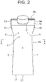
- FIG. 2 is a front view of the paper container of the first example.
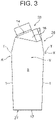
- FIG. 3 is a side view of the paper container of the first example.
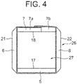
- FIG. 4 is a partially omitted enlarged sectional view taken along the line A-A of FIG. 2 .
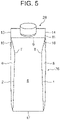
- FIG. 5 is a front view for illustrating a state in which a body right panel and a body left panel of the paper container of the first example, which have been in a recessed surface shape, are pushed out to deform center portions of the body right panel and the body left panel along a vertical direction into an approximately linear shape.
- FIG. 6 is a developed view of a carton blank for assembling the paper container of the first example.
- the paper container of the first example is a container having a flat top-type top portion, and is assembled with use of a carton blank having a development structure illustrated in FIG. 6 .
- the carton blank for assembling the paper container of the first example is made of a paper material having a thermoplastic resin laminated on each of a front surface and a back surface thereof.
- a body front panel 5, a body left side panel 6, a body back panel 7, and a body right side panel 8 are contiguous through body vertical folding lines 1, 2, 3, and 4.
- a pair of top panels 11 and 12 are contiguous with an upper end of the body front panel 5 and an upper end of the body back panel 7 so as to be opposed to the body front panel 5 and the body back panel 7 through a top portion horizontal folding line 9 and a top portion horizontal folding line 10, respectively.
- a pair of side panels 15 and 16 are contiguous with an upper end of the body left side panel 6 and an upper end of the body right side panel 8 so as to be opposed to the body left side panel 6 and the body right side panel 8 through a top portion horizontal folding line 13 and a top portion horizontal folding line 14, respectively.
- a pair of bottom panels 19 and 20 are contiguous with a lower end of the body front panel 5 and a lower end of the body back panel 7 so as to be opposed to the body front panel 5 and the body back panel 7 through a bottom portion horizontal folding line 17 and a bottom portion horizontal folding line 18, respectively.
- a pair of inner panels 23 and 24 are contiguous with a lower end of the body left side panel 6 and a lower end of the body right side panel 8 so as to be opposed to the body left side panel 6 and the body right side panel 8 through a bottom portion horizontal folding line 21 and a bottom portion horizontal folding line 22, respectively.
- each of the top panel 12 contiguous with the upper end of the body back panel 7 and the bottom panel 20 contiguous with the lower end of the body back panel 7 is divided into two in a vertical direction at a center position of each of surfaces of the panels.
- a vertical direction sealing panel 25 to be sealed on division edges of another body back panel 7b, another top panel 12b, and another bottom panel 20b is contiguous with division edges of one body back panel 7a, one top panel 12a, and one bottom panel 20a, which are formed by the division.
- the body vertical folding line 1 through which the body front panel 5 and the body right side panel 8 are contiguous with each other and the body vertical folding line 2 through which the body front panel 5 and the body left side panel 6 are contiguous with each other are approximately symmetrical bent lines bent in an approximately doglegged shape toward a center of the body front panel 5.
- the body vertical folding line 3 through which the body back panel 7 and the body left side panel 6 are contiguous with each other and the body vertical folding line 4 through which the body back panel 7 and the body right side panel 8 are contiguous with each other are approximately symmetrical bent lines bent in an approximately doglegged shape toward a center of the body back panel 7.
- bent top portions T of the body vertical folding lines 1, 2, 3, and 4 being the bent lines are located above a center of the body front panel 5 and a center of the body back panel 7 in the vertical direction.
- the carton blank is first mountain-folded along the body vertical folding lines 1, 2, 3, and 4. Then, the vertical direction sealing panel 25 contiguous with the division edges of the one body back panel 7a, the one top panel 12a, and the one bottom panel 20a, which are formed by the division, is sealed to the division edges of the another body back panel 7b, the another top panel 12b, and the another bottom panel 20b to form a quadrangular tubular body 26.
- the pair of bottom panels 19 and 20, which are respectively contiguous with the lower end of the body front panel 5 and the lower end of the body back panel 7, and the pair of inner panels 23 and 24, which are respectively contiguous with the lower end of the body left side panel 6 and the lower end of the body right side panel 8 of the tubular body 26, are folded inward and sealed so as to be tightly closed to form a bottom portion 27.
- the pair of top panels 11 and 12 which are respectively contiguous with the upper end of the body front panel 5 and the upper end of the body back panel 7, and the pair of side panels 15 and 16, which are respectively contiguous with the upper end of the body left side panel 6 and the upper end of the body right side panel 8, are folded inward and sealed so as to be tightly closed to form a top portion 28.
- the body vertical folding line 1 through which the body front panel 5 and the body right side panel 8 are contiguous with each other and the body vertical folding line 2 through which the body front panel 5 and the body left side panel 6 are contiguous with each other are the approximately symmetrical bent lines, which are bent toward the center of the body front panel 5, and the body vertical folding line 3 through which the body back panel 7 and the body left side panel 6 are contiguous with each other and the body vertical folding line 4 through which the body back panel 7 and the body right side panel 8 are contiguous with each other are the approximately symmetrical bent lines, which are bent toward the center of the body back panel 7.
- the body front panel 5 has a projecting surface X formed on a region between the bent top portions T of the body vertical folding lines 1 and 2, which is bent outward in accordance with bent angles of the body vertical folding lines 1 and 2.
- the body back panel 7 has a projecting surface X formed on a region between the bent top portions T of the body vertical folding lines 3 and 4, which is bent outward in accordance with bent angles of the body vertical folding lines 3 and 4 (see FIG. 3 ).
- the body left side panel 6 forms a recessed surface Y on a region between the bent top portions T of the body vertical folding lines 2 and 3, which is bent inward in accordance with the bent angles of the body vertical folding lines 2 and 3.
- the body right side panel 8 forms a recessed surface Y on a region between the bent top portions T of the body vertical folding lines 1 and 4, which is bent inward in accordance with the bent angles of the body vertical folding lines 1 and 4 (see FIG. 2 ).
- each of the body left side panel 6 and the body right side panel 8 of the tubular body 26 forms the recessed surface Y.
- the body left side panel 6 and the body right side panel 8 forming the recessed surfaces Y of the tubular body 26 are grabbed.
- the paper container is locked in such a manner that upper-side surfaces of the recessed surfaces Y of the body left side panel 6 and the body right side panel 8 are fingers are placed on the fingers.
- slippage of the paper container at the time of being grabbed can be reliably prevented.
- the bent top portions T of the body vertical folding lines 1, 2, 3, and 4 being the bent lines are located above the center of the body front panel 5 and the center of the body back panel 7 in the vertical direction.
- the paper container can be held in a stable state.
- FIG. 7 to FIG. 12 are illustrations of a second example according to the claimed invention.
- FIG. 7 is a perspective view for illustrating the paper container of this example.
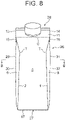
- FIG. 8 is a front view of the paper container of the second example.
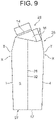
- FIG. 9 is a side view of the paper container of the second example.
- FIG. 10 is a partially omitted enlarged sectional view taken along the line B-B of FIG. 8 .
- FIG. 11 is an explanatory enlarged sectional view for illustrating a state in which a body left panel and a body right panel of the paper container of the second example are pushed inward to be deformed in a recessed surface shape.
- FIG. 12 is a developed view of a carton blank for assembling the paper container of the second example.
- the paper container of the second example is a container having a flat top-type top portion similarly to the first example, and is assembled with use of a carton blank having a development structure illustrated in FIG. 12 .
- the body left side panel 6 has a vertical folding line 30 formed at a center portion along the vertical direction, which is continuous with the top portion horizontal folding line 13 and the bottom portion horizontal folding line 21.
- the vertical folding line 30 forms a ridge portion 29 when the carton blank is mountain-folded along the vertical folding line 30.
- the body right side panel 8 has a vertical folding line 32 formed at the center portion thereof along the vertical direction, which is continuous with the top portion horizontal folding line 14 and the bottom portion horizontal folding line 22.
- the vertical folding line 32 forms a ridge portion 31 when the carton blank is mountain-folded along the vertical folding line 32.
- the carton blank is mountain-folded along the vertical folding line 30, which is continuous with the top portion horizontal folding line 13 and the bottom portion horizontal folding line 21 of the body left side panel 6, to thereby form the ridge portion 29 at the center portion of the body left side panel 6 along the vertical direction.
- the carton blank is mountain-folded along the vertical folding line 32, which is continuous with the top portion horizontal folding line 13 and the bottom portion horizontal folding line 21 of the body right side panel 8, to thereby form the ridge portion 31 at the center portion of the body right side panel 8 along the vertical direction.
- the carton blank is mountain-folded along the body vertical folding lines 1, 2, 3, and 4.
- the vertical direction sealing panel 25 contiguous with the division edges of the one body back panel 7a, the one top panel 12a, and the one bottom panel 20a, which are formed by the division, is sealed to the division edges of the another body back panel 7b, the another top panel 12b, and the another bottom panel 20b to form the quadrangular tubular body 26.
- the pair of bottom panels 19 and 20, which are respectively contiguous with the lower end of the body front panel 5 and the lower end of the body back panel 7, and the pair of bottom panels 23 and 34, which are respectively contiguous with the lower end of the body left side panel 6 and the lower end of the body right side panel 8 of the tubular body 26, are folded inward and sealed so as to be tightly closed to form the bottom portion 27.
- the pair of top panels 11 and 12 which are respectively contiguous with the upper end of the body front panel 5 and the upper end of the body back panel 7, and the pair of side panels 15 and 16, which are respectively contiguous with the upper end of the body left side panel 6 and the upper end of the body right side panel 8, are folded inward and sealed so as to be tightly closed to form the top portion 28.
- the body vertical folding line 1 through which the body front panel 5 and the body right side panel 8 are contiguous with each other and the body vertical folding line 2 through which the body front panel 5 and the body left side panel 6 are contiguous with each other are the approximately symmetrical bent lines bent toward the center of the body front panel 5.
- the body vertical folding line 3 through which the body back panel 7 and the body left side panel 6 are contiguous with each other and the body vertical folding line 4 through which the body back panel 7 and the body right side panel 8 are contiguous with each other are the approximately symmetrical bent lines bent toward the center of the body back panel 7.
- the body front panel 5 forms the projecting surface X on the region between the bent top portions T of the body vertical folding lines 1 and 2, which is bent outward in accordance with the bent angles of the body vertical folding lines 1 and 2.
- the body back panel 7 forms the projecting surface X formed on the region between the bent top portions T of the body vertical folding lines 3 and 4, which is bent outward in accordance with the bent angles of the body vertical folding lines 3 and 4 (see FIG. 9 ).
- the body left side panel 6 has an approximately linear center portion along the vertical direction because of the ridge portion 29 formed by the body left side panel 6 mountain-folded along the vertical folding line 30.
- the body left side panel 8 has an approximately linear center portion in the vertical direction because of the ridge portion 31 formed by the body right side panel 8 mountain-folded along the vertical folding line 32 (see FIG. 8 ).
- the ridge portion 29 formed at the center portion of each of the body left side panel 6 and the body right side panel 8 along the vertical direction serves as a rib to prevent bulge of the tubular body 26, which is caused by a weight of the stored liquid beverage.
- the region of the body left panel 6, which is located between the bent top portion T of the body vertical folding line 2 and the bent top portion T of the body vertical folding line 3 and the region of the body right panel 8, which is located between the bent top portion T of the body vertical folding line 1 and the bent top portion T of the body vertical folding line 4 are grabbed so as to press the regions.
- the body left panel 6 and the body right panel 8 are elastically deformed to form the recessed surfaces Y (see FIG. 11 ).
- the paper container can easily be held.
- Each of the paper container of the first example and the paper container of the second example is a paper container having a flat top-type top portion.
- the present invention can also be carried out for a gable top-type paper container.
Description
- The present invention relates to a paper container having a flat top-type top portion (including a brick-type paper container) and a paper container having a gable top-type top portion, which are configured to store a liquid beverage such as milk or juice.
- Hitherto, a flat top-type paper container and a gable top-type paper container have been widely used. The flat top-type paper container includes four body panels. On a body formed into a quadrangular tubular shape through sealing with a vertical direction sealing panel, the flat top-type paper container has a top portion formed of a pair of top panels and a pair of side panels folded on an inner side of the top panels. Below the body, the flat top-type paper container has a bottom portion formed of a pair of bottom panels and a pair of inner panels folded on an inner side of the bottom panels. The gable top-type paper container has a top portion formed of a pair of gable top forming panels and a pair of gable wall forming panels folded on an inner side of the gable top forming panels. Below the body, the gable top-type paper container has a bottom portion formed of a pair of bottom panels and a pair of inner panels folded on an inner side of the bottom panels.
- In the above-mentioned types of paper container, each of the body panels of the body formed in the quadrangular tubular shape generally has a flat surface. Thus, the body does not have any portion that is to be caught by fingers when the body of the paper container is grabbed. Therefore, it is unstable and difficult to keep holding the paper container. Especially when a volume of the paper container is large or water droplets are present on a surface of the paper container due to dew condensation, there is a fear in that the paper container slips and falls out of the hand.
- As a paper container capable of coping with the circumstances described above, there has been proposed a paper container having a ridge, which is formed on each of body panels of a body so as to be parallel to a bottom portion. A region continuous with the ridge at a corner portion at which the body panels adjacent to each other intersect with each other, specifically, in a ridgeline portion and the vicinity thereof is formed as a recess (see, for example, Patent Literature 1).
- The paper container described in
Patent Literature 1 is easy to grab and can be held without slippage owing to the ridge formed on each of the body panels of the body. -
- The paper container described in
Patent Literature 1 is easy to grab and can be held without slippage owing to the ridge formed on each of the body panels of the body. However, the ridges project from the body of the paper container, and hence there is a problem in that the ridges may be damaged during storage and conveyance of the paper container. - Further, prevention of the slippage is influenced by a projecting height of the ridge. When the height of each of the ridges is low, the paper container is liable to be more slippery when being grabbed. Thus, in order to more reliably enhance the prevention of the slippage, it is inevitably required that the height of each of the ridges be increased. However, in a case in which the height of each of the ridges is increased, for example, when the paper containers are arranged side by side, a large gap is formed between the paper containers. Thus, the amount of storage of paper containers and the amount of conveyance of paper containers are reduced. As a result, there arises a problem in that, for example, the storage and conveyance of paper containers are adversely affected.
- An object of the present invention is to provide a paper container, which is capable of preventing slippage at the time of grabbing the paper container to provide ease of holding and is less liable to adversely affect, for example, storage and conveyance of the paper container.
- In order to achieve the object described above, according to the invention described in
claim 1, there is provided a paper container, which is made of a paper material having a thermoplastic resin laminated on each of a front surface and a back surface thereof, the paper container including: a body front panel, a body right side panel, a body left side panel, a body back panel, which are contiguous through body vertical folding lines; a vertical direction sealing panel configured to form a quadrangular tubular body; a pair of top panels contiguous with an upper end of the body front panel and an upper end of the body back panel so as to be opposed to the body front panel and the body back panel through top portion horizontal folding lines, respectively; a pair of side panels contiguous with an upper end of the body right side panel and an upper end of the body left side panel so as to be opposed to the body right side panel and the body left side panel through top portion horizontal folding lines, respectively, the pair of top panels and the pair of side panels being folded inward and sealed so as to be tightly closed to form a top portion; and a pair of bottom panels contiguous with a lower end of the body front panel and a lower end of the body back panel so as to be opposed to the body front panel and the body back panel through bottom portion horizontal folding lines, respectively; and a pair of inner panels contiguous with a lower end of the body right side panel and a lower end of the body left side panel so as to be opposed to the body right side panel and the body left side panel through bottom portion horizontal folding lines, the pair of bottom panels and the pair of inner panels being folded inward and sealed so as to be tightly closed to form a bottom portion, wherein the body vertical folding line through which the body front panel and the body right side panel are contiguous with each other and the body vertical folding line through which the body front panel and the body left side panel are contiguous with each other are approximately symmetrical bent lines bent toward a center of the body front panel, and the body vertical folding line through which the body back panel and the body right side panel are contiguous with each other and the body vertical folding line through which the body back panel and the body left side panel are contiguous with each other are approximately symmetrical bent lines bent toward a center of the body back panel. - Furthermore, bent top portions of the body vertical folding lines are located above a center of the body front panel and a center of the body back panel in a vertical direction.
- Furthermore, the body right side panel and the body left side panel have ridge portions formed at respective center portions so as to extend along a vertical direction, and the ridge portions are formed of mountain-folded vertical folding lines.
- In one form the body back panel, one of the top panels, which is contiguous with the upper end of the body back panel, and one of the bottom panels, which is contiguous with the lower end of the body back panel, are divided into two at a center position of each of surfaces of the body back panel, the one top panel, and the one bottom panel in the vertical direction, wherein the vertical direction sealing panel is contiguous with division edges of one divided piece of the body back panel, one divided piece of the one top panel, and one divided piece of the one bottom panel, and wherein the vertical direction sealing panel is sealed to division edges of another divided pieces to form the quadrangular tubular body.
- With the paper container described in
claim 1, the body vertical folding line through which the body front panel and the body right side panel are contiguous with each other and the body vertical folding line through which the body front panel and the body left side panel are contiguous with each other are the approximately symmetrical bent lines bent toward the center of the body front panel, and the body vertical folding line through which the body back panel and the body right side panel are contiguous with each other and the body vertical folding line through which the body back panel and the body left side panel are contiguous with each other are the approximately symmetrical bent lines bent toward the center of the body back panel. Thus, in the tubular body formed of the body front panel, the body right side panel, the body left side panel, and the body back panel, which are contiguous through the body vertical folding lines being the bent lines therebetween, each of the body front panel and the body back panel has a projecting surface on a region between the bent top portions of the body vertical folding lines opposed to each other, which is bent outward in accordance with a bent angle of each of the body vertical folding lines. Each of the body left side panel and the body right side panel has a recessed surface on a region between the bent top portions of the body vertical folding lines opposed to each other, which is bent inward in accordance with the bent angle of each of the body vertical folding lines. - At the time of holding the paper container, the body right side panel and the body left side panel forming the recessed surfaces of the tubular body are grabbed. As a result, the paper container is locked in such a manner that upper-side surfaces of the recessed surfaces of the body right side panel and the body left side panel are placed on the fingers. Thus, slippage of the paper container at the time of grabbed can be reliably prevented. Accordingly, the paper container can easily be held without being strongly grabbed.
- Further, even in a case in which the body right side panel and the body left side panel forming the recessed surfaces are pushed out to deform the center portion of the body right side panel and the center portion of the body left side panel along the vertical direction into an approximately linear shape due to, for example, pressing on the body front panel and the body back panel of the tubular body from an outer side or an internal pressure of the tubular body, when the region of the body right side panel, which is located between the bent top portions of the body vertical folding lines opposed to each other, and the region of the body left side panel, which is located between the bent top portions of the body vertical folding lines opposed to each other, are grabbed so as to be pressed, the body right side panel and the body left side panel are elastically deformed to form the recessed surfaces. Accordingly, the paper container can easily be held.
- Further, the tubular body does not have ridges as those formed on a paper container described in
Patent Literature 1. Thus, there is no fear of, for example, adversely affecting storage and conveyance of the paper container. - Furthermore, the bent top portions of the body vertical folding lines are located above the center of the body front panel and the center of the body back panel in the vertical direction. Thus, the paper container can be held in a stable state.
- Furthermore, the body right side panel and the body left side panel have the ridge portions formed at respective center portions so as to extend along the vertical direction, and the ridge portions are formed of mountain-folded vertical folding lines. Thus, the ridge portions serves as ribs to prevent bulge of the body due to a weight of a liquid beverage stored therein.
- At the time of holding the paper container, the ridge portion in the region of the body right panel of the tubular body, which is located between the bent top portions of the body vertical folding lines opposed to each other, and the ridge portion in the region of the body left panel, which is located between the bent top portions of the body vertical folding lines opposed to each other, are grabbed so as to be pressed inward. As a result, the body right panel and the body left panel are elastically deformed to form the recessed surfaces. Thus, the paper container can easily be held.
- According to the invention described in
claim 2, the body back panel, one of the top panels, which is contiguous with the upper end of the body back panel, and one of the bottom panels, which is contiguous with the lower end of the body back panel, are divided into two at a center position of each of surfaces of the body back panel, the one top panel, and the one bottom panel in the vertical direction. The vertical direction sealing panel is contiguous with division edges of one divided piece of the body back panel, one divided piece of the one top panel, and one divided piece of the one bottom panel. The vertical direction sealing panel is sealed to division edges of another divided pieces to form the quadrangular tubular body. Accordingly, the quadrangular tubular body can easily be formed. -
-
FIG. 1 is a perspective view for illustrating a first example of a paper container helpful for understanding construction of the present invention. -
FIG. 2 is a front view of the paper container of the first example. -
FIG. 3 is a side view of the paper container of the first example. -
FIG. 4 is a partially omitted enlarged sectional view taken along the line A-A ofFIG. 2 . -
FIG. 5 is a front view for illustrating a state in which a body right panel and a body left panel of the paper container of the first example, which have been in a recessed surface shape, are pushed out to deform center portions of the body right panel and the body left panel along a vertical direction into an approximately linear shape. -
FIG. 6 is a developed view of a carton blank for assembling the paper container of the first example. -
FIG. 7 is a perspective view for illustrating a second example of paper container embodying the present invention. -
FIG. 8 is a front view of the paper container of the second example. -
FIG. 9 is a side view of the paper container of the second example. -
FIG. 10 is a partially omitted enlarged sectional view taken along the line B-B ofFIG. 8 . -
FIG. 11 is an explanatory enlarged sectional view for illustrating a state in which a body left panel and a body right panel of the paper container of the second example are pushed inward to be deformed into a recessed surface shape. -
FIG. 12 is a developed view of a carton blank for assembling the paper container of the second example. - Now, a paper container is described in detail with reference to the drawings.
FIG. 1 to FIG. 6 are illustrations of a first example of paper container, in whichFIG. 1 is a perspective view of the paper container of the first example.FIG. 2 is a front view of the paper container of the first example.FIG. 3 is a side view of the paper container of the first example.FIG. 4 is a partially omitted enlarged sectional view taken along the line A-A ofFIG. 2 .FIG. 5 is a front view for illustrating a state in which a body right panel and a body left panel of the paper container of the first example, which have been in a recessed surface shape, are pushed out to deform center portions of the body right panel and the body left panel along a vertical direction into an approximately linear shape.FIG. 6 is a developed view of a carton blank for assembling the paper container of the first example. - The paper container of the first example is a container having a flat top-type top portion, and is assembled with use of a carton blank having a development structure illustrated in
FIG. 6 . - The carton blank for assembling the paper container of the first example is made of a paper material having a thermoplastic resin laminated on each of a front surface and a back surface thereof. A
body front panel 5, a bodyleft side panel 6, a body backpanel 7, and a bodyright side panel 8 are contiguous through bodyvertical folding lines - A pair of
top panels body front panel 5 and an upper end of the body backpanel 7 so as to be opposed to thebody front panel 5 and the body backpanel 7 through a top portionhorizontal folding line 9 and a top portionhorizontal folding line 10, respectively. A pair ofside panels side panel 6 and an upper end of the bodyright side panel 8 so as to be opposed to the body leftside panel 6 and the bodyright side panel 8 through a top portionhorizontal folding line 13 and a top portionhorizontal folding line 14, respectively. - Further, a pair of
bottom panels body front panel 5 and a lower end of the body backpanel 7 so as to be opposed to thebody front panel 5 and the body backpanel 7 through a bottom portionhorizontal folding line 17 and a bottom portionhorizontal folding line 18, respectively. A pair ofinner panels side panel 6 and a lower end of the bodyright side panel 8 so as to be opposed to the body leftside panel 6 and the bodyright side panel 8 through a bottom portionhorizontal folding line 21 and a bottom portionhorizontal folding line 22, respectively. - Further, each of the
top panel 12 contiguous with the upper end of the body backpanel 7 and thebottom panel 20 contiguous with the lower end of the body backpanel 7 is divided into two in a vertical direction at a center position of each of surfaces of the panels. A verticaldirection sealing panel 25 to be sealed on division edges of another body backpanel 7b, anothertop panel 12b, and anotherbottom panel 20b is contiguous with division edges of one body backpanel 7a, onetop panel 12a, and onebottom panel 20a, which are formed by the division. - Further, the body
vertical folding line 1 through which thebody front panel 5 and the bodyright side panel 8 are contiguous with each other and the bodyvertical folding line 2 through which thebody front panel 5 and the body leftside panel 6 are contiguous with each other are approximately symmetrical bent lines bent in an approximately doglegged shape toward a center of thebody front panel 5. Similarly, the bodyvertical folding line 3 through which the body backpanel 7 and the body leftside panel 6 are contiguous with each other and the bodyvertical folding line 4 through which the body backpanel 7 and the bodyright side panel 8 are contiguous with each other are approximately symmetrical bent lines bent in an approximately doglegged shape toward a center of the body backpanel 7. - In the first example, bent top portions T of the body
vertical folding lines body front panel 5 and a center of the body backpanel 7 in the vertical direction. - For assembly of the paper container of this example with use of the carton blank having the development structure described above, the carton blank is first mountain-folded along the body
vertical folding lines direction sealing panel 25 contiguous with the division edges of the one body backpanel 7a, the onetop panel 12a, and the onebottom panel 20a, which are formed by the division, is sealed to the division edges of the another body backpanel 7b, the anothertop panel 12b, and the anotherbottom panel 20b to form a quadrangulartubular body 26. - Next, the pair of
bottom panels body front panel 5 and the lower end of the body backpanel 7, and the pair ofinner panels side panel 6 and the lower end of the bodyright side panel 8 of thetubular body 26, are folded inward and sealed so as to be tightly closed to form abottom portion 27. - Then, after a liquid beverage is filled in, the pair of
top panels body front panel 5 and the upper end of the body backpanel 7, and the pair ofside panels side panel 6 and the upper end of the bodyright side panel 8, are folded inward and sealed so as to be tightly closed to form atop portion 28. - In the paper container assembled as described above, the body
vertical folding line 1 through which thebody front panel 5 and the bodyright side panel 8 are contiguous with each other and the bodyvertical folding line 2 through which thebody front panel 5 and the body leftside panel 6 are contiguous with each other are the approximately symmetrical bent lines, which are bent toward the center of thebody front panel 5, and the bodyvertical folding line 3 through which the body backpanel 7 and the body leftside panel 6 are contiguous with each other and the bodyvertical folding line 4 through which the body backpanel 7 and the bodyright side panel 8 are contiguous with each other are the approximately symmetrical bent lines, which are bent toward the center of the body backpanel 7. Thus, in thetubular body 26 formed of thebody front surface 5, the body leftside panel 6, the bodyright side panel 8, and the body backpanel 7, which are contiguous through the bodyvertical folding lines body front panel 5 has a projecting surface X formed on a region between the bent top portions T of the bodyvertical folding lines vertical folding lines panel 7 has a projecting surface X formed on a region between the bent top portions T of the bodyvertical folding lines vertical folding lines 3 and 4 (seeFIG. 3 ). - Further, the body left
side panel 6 forms a recessed surface Y on a region between the bent top portions T of the bodyvertical folding lines vertical folding lines right side panel 8 forms a recessed surface Y on a region between the bent top portions T of the bodyvertical folding lines vertical folding lines 1 and 4 (seeFIG. 2 ). - As described above, each of the body left
side panel 6 and the bodyright side panel 8 of thetubular body 26 forms the recessed surface Y. Thus, at the time of holding the paper container is held, the body leftside panel 6 and the bodyright side panel 8 forming the recessed surfaces Y of thetubular body 26 are grabbed. As a result, the paper container is locked in such a manner that upper-side surfaces of the recessed surfaces Y of the body leftside panel 6 and the bodyright side panel 8 are fingers are placed on the fingers. Thus, slippage of the paper container at the time of being grabbed can be reliably prevented. - Further, even in a case in which the body left
side panel 6 and the bodyright side panel 8 forming the recessed surface Y are pushed out to deform the center portion of the body leftside panel 6 and the center portion of the bodyright side panel 8 along the vertical direction into an approximately linear shape due to, for example, external pressing on thebody front panel 5 and the body backpanel 7 of thetubular body 26 or an internal pressure of the tubular body 26 (seeFIG. 5 ), when the region of the body leftside panel 6, which is located between the bent top portions T of the bodyvertical folding lines right side panel 8, which is located between the bent top portions T of the bodyvertical folding lines side panel 6 and the bodyright side panel 8 are elastically deformed to form the recessed surfaces Y. Accordingly, the paper container can easily be held. - Further, in the first example, the bent top portions T of the body
vertical folding lines body front panel 5 and the center of the body backpanel 7 in the vertical direction. Thus, the paper container can be held in a stable state. -
FIG. 7 to FIG. 12 are illustrations of a second example according to the claimed invention.FIG. 7 is a perspective view for illustrating the paper container of this example.FIG. 8 is a front view of the paper container of the second example.FIG. 9 is a side view of the paper container of the second example.FIG. 10 is a partially omitted enlarged sectional view taken along the line B-B ofFIG. 8 .FIG. 11 is an explanatory enlarged sectional view for illustrating a state in which a body left panel and a body right panel of the paper container of the second example are pushed inward to be deformed in a recessed surface shape.FIG. 12 is a developed view of a carton blank for assembling the paper container of the second example. - The same configurations of the paper container of the second example as those of the first example are denoted by the same reference symbols, and the description thereof is omitted. Only configurations different from those of the first example are described.
- The paper container of the second example is a container having a flat top-type top portion similarly to the first example, and is assembled with use of a carton blank having a development structure illustrated in
FIG. 12 . On the carton blank for assembling the paper container of the second example, the body leftside panel 6 has avertical folding line 30 formed at a center portion along the vertical direction, which is continuous with the top portionhorizontal folding line 13 and the bottom portionhorizontal folding line 21. Thevertical folding line 30 forms aridge portion 29 when the carton blank is mountain-folded along thevertical folding line 30. Similarly, the bodyright side panel 8 has avertical folding line 32 formed at the center portion thereof along the vertical direction, which is continuous with the top portionhorizontal folding line 14 and the bottom portionhorizontal folding line 22. Thevertical folding line 32 forms aridge portion 31 when the carton blank is mountain-folded along thevertical folding line 32. - The other configurations are the same as those of the carton blank of the first example, which is illustrated in
FIG. 6 . - For the assembly of the paper container of this example with use of the carton blank having the development structure described above, the carton blank is mountain-folded along the
vertical folding line 30, which is continuous with the top portionhorizontal folding line 13 and the bottom portionhorizontal folding line 21 of the body leftside panel 6, to thereby form theridge portion 29 at the center portion of the body leftside panel 6 along the vertical direction. Similarly, the carton blank is mountain-folded along thevertical folding line 32, which is continuous with the top portionhorizontal folding line 13 and the bottom portionhorizontal folding line 21 of the bodyright side panel 8, to thereby form theridge portion 31 at the center portion of the bodyright side panel 8 along the vertical direction. - The other configurations are the same as those of the carton blank of the first example, which is illustrated in
FIG. 6 . - Next, similarly to the first example, the carton blank is mountain-folded along the body
vertical folding lines direction sealing panel 25 contiguous with the division edges of the one body backpanel 7a, the onetop panel 12a, and the onebottom panel 20a, which are formed by the division, is sealed to the division edges of the another body backpanel 7b, the anothertop panel 12b, and the anotherbottom panel 20b to form the quadrangulartubular body 26. - Next, the pair of
bottom panels body front panel 5 and the lower end of the body backpanel 7, and the pair ofbottom panels 23 and 34, which are respectively contiguous with the lower end of the body leftside panel 6 and the lower end of the bodyright side panel 8 of thetubular body 26, are folded inward and sealed so as to be tightly closed to form thebottom portion 27. - Then, after a liquid beverage is filled in, the pair of
top panels body front panel 5 and the upper end of the body backpanel 7, and the pair ofside panels side panel 6 and the upper end of the bodyright side panel 8, are folded inward and sealed so as to be tightly closed to form thetop portion 28. - In the paper container assembled as described above, the body
vertical folding line 1 through which thebody front panel 5 and the bodyright side panel 8 are contiguous with each other and the bodyvertical folding line 2 through which thebody front panel 5 and the body leftside panel 6 are contiguous with each other are the approximately symmetrical bent lines bent toward the center of thebody front panel 5. The bodyvertical folding line 3 through which the body backpanel 7 and the body leftside panel 6 are contiguous with each other and the bodyvertical folding line 4 through which the body backpanel 7 and the bodyright side panel 8 are contiguous with each other are the approximately symmetrical bent lines bent toward the center of the body backpanel 7. Thus, in thetubular body 26 formed of thebody front surface 5, the body leftside panel 6, the bodyright side panel 8, and the body backpanel 7, thebody front panel 5 forms the projecting surface X on the region between the bent top portions T of the bodyvertical folding lines vertical folding lines panel 7 forms the projecting surface X formed on the region between the bent top portions T of the bodyvertical folding lines vertical folding lines 3 and 4 (seeFIG. 9 ). - Further, the body left
side panel 6 has an approximately linear center portion along the vertical direction because of theridge portion 29 formed by the body leftside panel 6 mountain-folded along thevertical folding line 30. The body leftside panel 8 has an approximately linear center portion in the vertical direction because of theridge portion 31 formed by the bodyright side panel 8 mountain-folded along the vertical folding line 32 (seeFIG. 8 ). - As described above, the
ridge portion 29 formed at the center portion of each of the body leftside panel 6 and the bodyright side panel 8 along the vertical direction serves as a rib to prevent bulge of thetubular body 26, which is caused by a weight of the stored liquid beverage. - At the time of holding the paper container, the region of the body left
panel 6, which is located between the bent top portion T of the bodyvertical folding line 2 and the bent top portion T of the bodyvertical folding line 3 and the region of the bodyright panel 8, which is located between the bent top portion T of the bodyvertical folding line 1 and the bent top portion T of the bodyvertical folding line 4 are grabbed so as to press the regions. As a result, the body leftpanel 6 and the bodyright panel 8 are elastically deformed to form the recessed surfaces Y (seeFIG. 11 ). Thus, the paper container can easily be held. - Each of the paper container of the first example and the paper container of the second example is a paper container having a flat top-type top portion. The present invention can also be carried out for a gable top-type paper container.
-
- 1, 2, 3, 4
- body vertical folding line
- 5
- body front panel
- 6
- body left side panel
- 7
- body back panel
- 7a
- one divided body back panel
- 7b
- another divided body back panel
- 8
- body right side panel
- 9, 10
- top portion horizontal folding line
- 11, 12
- top panel
- 12a
- one top panel
- 12b
- another top panel
- 13, 14
- top portion horizontal folding line
- 15, 16
- side panel
- 17, 18
- bottom portion horizontal folding line
- 19, 20
- bottom panel
- 20a
- one bottom panel
- 20b
- another bottom panel
- 21, 22
- bottom portion horizontal folding line
- 23, 24
- inner panel
- 25
- vertical direction sealing panel
- 26
- tubular body
- 27
- bottom portion
- 28
- top portion
- 29
- ridge portion
- 30
- vertical folding line
- 31
- ridge portion
- 32
- vertical folding line
- T
- bent top portion
- X
- projecting surface
- Y
- recessed surface
Claims (2)
- A paper container, which is made of a paper material having a thermoplastic resin laminated on each of a front surface and a back surface thereof, the paper container comprising:a body front panel (5), a body right side panel (8), a body left side panel (6), a body back panel (7), which are contiguous through body vertical folding lines (1, 2, 3, 4);a vertical direction sealing panel (25) configured to form a quadrangular tubular body (26);a pair of top panels (11, 12) contiguous with an upper end of the body front panel (5) and an upper end of the body back panel (7) so as to be opposed to the body front panel (5) and the body back panel (7) through top portion horizontal folding lines (9, 10), respectively;a pair of side panels (15, 16) contiguous with an upper end of the body right side panel (8) and an upper end of the body left side panel (6) so as to be opposed to the body right side panel (8) and the body left side panel (7) through top portion horizontal folding lines (13, 14), respectively, the pair of top panels (11, 12) and the pair of side panels (15, 16) being folded inward and sealed so as to be tightly closed to form a top portion (28); anda pair of bottom panels (19, 20) contiguous with a lower end of the body front panel (5) and a lower end of the body back panel (7) so as to be opposed to the body front panel (5) and the body back panel (7) through bottom portion horizontal folding lines (17, 18), respectively; anda pair of inner panels (23, 24) contiguous with a lower end of the body right side panel (8) and a lower end of the body left side panel (6) so as to be opposed to the body right side panel (8) and the body left side panel (6) through bottom portion horizontal folding lines (21, 22), the pair of bottom panels (19, 20) and the pair of inner panels (23, 24) being folded inward and sealed so as to be tightly closed to form a bottom portion (27);wherein the body vertical folding line (1) through which the body front panel (5) and the body right side panel (8) are contiguous with each other and the body vertical folding line (2) through which the body front panel (5) and the body left side panel (6) are contiguous with each other are approximately symmetrical bent lines bent toward a center of the body front panel (5), and the body vertical folding line (4) through which the body back panel (7) and the body right side panel (8) are contiguous with each other and the body vertical folding line (3) through which the body back panel (7) and the body left side panel (6) are contiguous with each other are approximately symmetrical bent lines bent toward a center of the body back panel (7); characterised in thatbent top portions (T) of the body vertical folding lines (1, 2, 3, 4) being the bent lines are located above a center of the body front panel (5) and a center of the body back panel (7) in a vertical direction; and in that the body right side panel (8) and the body left side panel (6) have ridge portions (29, 31) formed at respective center portions so as to extend along a vertical direction, and the ridge portions (29, 31) are formed of mountain-folded vertical folding lines (30, 32).
- The paper container according to claim 1,wherein the body back panel (7), one of the top panels (11, 12), which is contiguous with the upper end of the body back panel, and one of the bottom panels (19, 20), which is contiguous with the lower end of the body back panel (7), are divided into two at a center position of each of surfaces of the body back panel, the one top panel, and the one bottom panel in the vertical direction,wherein the vertical direction sealing panel (25) is contiguous with division edges of one divided piece of the body back panel (7), one divided piece of the one top panel, and one divided piece of the one bottom panel, andwherein the vertical direction sealing panel (25) is sealed to division edges of another divided pieces to form the quadrangular tubular body.
Applications Claiming Priority (2)
| Application Number | Priority Date | Filing Date | Title |
|---|---|---|---|
| JP2017070072A JP6618085B2 (en) | 2017-03-31 | 2017-03-31 | Paper container |
| PCT/JP2018/012448 WO2018181321A1 (en) | 2017-03-31 | 2018-03-27 | Paper container |
Publications (3)
| Publication Number | Publication Date |
|---|---|
| EP3604151A1 EP3604151A1 (en) | 2020-02-05 |
| EP3604151A4 EP3604151A4 (en) | 2020-12-16 |
| EP3604151B1 true EP3604151B1 (en) | 2022-08-24 |
Family
ID=63675929
Family Applications (1)
| Application Number | Title | Priority Date | Filing Date |
|---|---|---|---|
| EP18775103.7A Active EP3604151B1 (en) | 2017-03-31 | 2018-03-27 | Paper container |
Country Status (12)
| Country | Link |
|---|---|
| US (1) | US11014703B2 (en) |
| EP (1) | EP3604151B1 (en) |
| JP (1) | JP6618085B2 (en) |
| KR (1) | KR102349587B1 (en) |
| CN (1) | CN110446661B (en) |
| DK (1) | DK3604151T3 (en) |
| ES (1) | ES2929114T3 (en) |
| PH (1) | PH12019502225A1 (en) |
| PL (1) | PL3604151T3 (en) |
| SG (1) | SG11201909031WA (en) |
| TW (1) | TWI752206B (en) |
| WO (1) | WO2018181321A1 (en) |
Families Citing this family (5)
| Publication number | Priority date | Publication date | Assignee | Title |
|---|---|---|---|---|
| USD915196S1 (en) * | 2018-06-14 | 2021-04-06 | Tetra Laval Holdings & Finance S.A. | Package and packaging sheet for foodstuff |
| JP7152894B2 (en) * | 2018-07-23 | 2022-10-13 | 日本製紙株式会社 | paper container |
| JP2021533045A (en) * | 2018-08-06 | 2021-12-02 | テトラ ラバル ホールディングス アンド ファイナンス エス エイ | Blanks for carton and carton packages |
| JP6821633B2 (en) * | 2018-09-21 | 2021-01-27 | 日本製紙株式会社 | Paper container |
| TWD204801S (en) * | 2019-07-09 | 2020-05-21 | 韓商賓格樂股份有限公司 | Packaging container for beverage |
Citations (2)
| Publication number | Priority date | Publication date | Assignee | Title |
|---|---|---|---|---|
| US3390827A (en) * | 1966-04-05 | 1968-07-02 | Chevron Res | Container having a series of convolutions along the side walls thereof and container blank for forming same |
| CN2853632Y (en) * | 2005-12-27 | 2007-01-03 | 赵勇 | Beverage box with step-shaped top |
Family Cites Families (21)
| Publication number | Priority date | Publication date | Assignee | Title |
|---|---|---|---|---|
| US4846396A (en) * | 1988-06-03 | 1989-07-11 | Frank Palazzolo | Container made of folded planar material having precreased gripping area and blank for same and method of manufacture |
| DE3835390A1 (en) * | 1988-10-18 | 1990-04-19 | Pkl Verpackungssysteme Gmbh | SQUARE PACK, IN PARTICULAR FROM A CARDBOARD PLASTIC COMPOSITE FOR LIQUIDS, SOUPS OD. DGL. AND METHOD FOR THE PRODUCTION THEREOF |
| JPH0571123A (en) | 1991-09-09 | 1993-03-23 | Okabe Co Ltd | Lock bolt construction method for soft earth slope and lock bolt |
| JPH0571123U (en) * | 1992-03-02 | 1993-09-24 | 花王株式会社 | Folding container |
| DE29518831U1 (en) * | 1995-11-28 | 1996-02-22 | Verpackungswerk Colordruck W M | Cardboard packaging and closure for a cardboard packaging |
| US6182887B1 (en) * | 1999-04-16 | 2001-02-06 | Tetra Laval Holdings & Finance, Sa | Package with extended top panel and a blank therefor |
| EP1275588A1 (en) * | 2001-07-12 | 2003-01-15 | Tetra Laval Holdings & Finance SA | Gable-top package for pourable food products |
| JP4442796B2 (en) * | 2003-01-24 | 2010-03-31 | 日本テトラパック株式会社 | Packaging container and spigot attached to packaging container |
| EP1732814A2 (en) * | 2004-04-08 | 2006-12-20 | Elopak Systems Ag | Improvements in or relating to packaging |
| JP2007055637A (en) | 2005-08-23 | 2007-03-08 | Nihon Tetra Pak Kk | Roof-type paper container |
| ATE444900T1 (en) * | 2006-02-28 | 2009-10-15 | Tetra Laval Holdings & Finance | BENDING DEVICE AND METHOD FOR SHAPING A GABLE PART OF A SEALED PACKAGING WITH FLOWING FOODS |
| DE102007004427A1 (en) * | 2007-01-23 | 2008-07-24 | Ingo Kern | Box-shaped drink package preparing method, involves bending flat rectangular body around bending line above center of rectangular body about angle of specific degrees, so that upper corners are inserted into housing packet |
| US7523853B2 (en) * | 2007-05-29 | 2009-04-28 | Tetra Laval Holdings & Finance. S.A. | Carton and blank for carton with corner indent wall |
| GB0802518D0 (en) * | 2008-02-12 | 2008-03-19 | Elopak Systems | Container made of material, blank and methods |
| GB0809082D0 (en) * | 2008-05-20 | 2008-06-25 | Elopak Systems | Improvements in or relating to container blanks and containers |
| GB0823051D0 (en) * | 2008-12-18 | 2009-01-28 | Elopak Systems | Improvements in or relating to packaging |
| EP2392517A1 (en) * | 2010-06-07 | 2011-12-07 | Tetra Laval Holdings & Finance S.A. | Sealed package for pourable food products and packaging material for producing sealed packages for pourable food products |
| JP5757824B2 (en) * | 2011-08-26 | 2015-08-05 | 日本製紙株式会社 | Paper container |
| GB201117986D0 (en) * | 2011-10-18 | 2011-11-30 | Elopak Systems | Improvements in or relating to packaging |
| JP2014015256A (en) * | 2012-07-11 | 2014-01-30 | Nihon Tetra Pak Kk | Manufacturing method of packaging container, and packaging container |
| JP6363839B2 (en) * | 2013-08-06 | 2018-07-25 | 月桂冠株式会社 | Liquid storage container |
-
2017
- 2017-03-31 JP JP2017070072A patent/JP6618085B2/en active Active
-
2018
- 2018-03-27 PL PL18775103.7T patent/PL3604151T3/en unknown
- 2018-03-27 US US16/498,547 patent/US11014703B2/en active Active
- 2018-03-27 EP EP18775103.7A patent/EP3604151B1/en active Active
- 2018-03-27 KR KR1020197028070A patent/KR102349587B1/en active IP Right Grant
- 2018-03-27 WO PCT/JP2018/012448 patent/WO2018181321A1/en active Application Filing
- 2018-03-27 ES ES18775103T patent/ES2929114T3/en active Active
- 2018-03-27 DK DK18775103.7T patent/DK3604151T3/en active
- 2018-03-27 SG SG11201909031W patent/SG11201909031WA/en unknown
- 2018-03-27 CN CN201880022305.9A patent/CN110446661B/en active Active
- 2018-03-30 TW TW107111115A patent/TWI752206B/en active
-
2019
- 2019-09-26 PH PH12019502225A patent/PH12019502225A1/en unknown
Patent Citations (2)
| Publication number | Priority date | Publication date | Assignee | Title |
|---|---|---|---|---|
| US3390827A (en) * | 1966-04-05 | 1968-07-02 | Chevron Res | Container having a series of convolutions along the side walls thereof and container blank for forming same |
| CN2853632Y (en) * | 2005-12-27 | 2007-01-03 | 赵勇 | Beverage box with step-shaped top |
Also Published As
| Publication number | Publication date |
|---|---|
| US11014703B2 (en) | 2021-05-25 |
| TWI752206B (en) | 2022-01-11 |
| KR20190135479A (en) | 2019-12-06 |
| PL3604151T3 (en) | 2022-11-28 |
| EP3604151A1 (en) | 2020-02-05 |
| JP6618085B2 (en) | 2019-12-11 |
| WO2018181321A1 (en) | 2018-10-04 |
| CN110446661B (en) | 2021-09-07 |
| JP2018172127A (en) | 2018-11-08 |
| DK3604151T3 (en) | 2022-09-12 |
| ES2929114T3 (en) | 2022-11-24 |
| CN110446661A (en) | 2019-11-12 |
| TW201841801A (en) | 2018-12-01 |
| SG11201909031WA (en) | 2019-11-28 |
| KR102349587B1 (en) | 2022-01-10 |
| PH12019502225A1 (en) | 2020-07-06 |
| US20200095012A1 (en) | 2020-03-26 |
| EP3604151A4 (en) | 2020-12-16 |
Similar Documents
| Publication | Publication Date | Title |
|---|---|---|
| EP3604151B1 (en) | Paper container | |
| US6929171B1 (en) | Stackable folding containers with pouring devices | |
| EP3828095B1 (en) | Paper container | |
| CN108349623B (en) | Paper inner container for storing liquid content for refilling | |
| JP2015174661A (en) | paper tray | |
| JP6496170B2 (en) | Liquid paper container | |
| JP2010006459A (en) | Paper container | |
| JP6571429B2 (en) | Paper container | |
| JP6399818B2 (en) | Packaging box | |
| JP6742148B2 (en) | Packaging container with stacking function | |
| JP2017052529A (en) | Outer packaging corrugated box of bag-in-box | |
| JP2016169025A (en) | Paper container | |
| JP6398290B2 (en) | Paper container | |
| JP4871626B2 (en) | Stacked packaging container | |
| KR200276077Y1 (en) | Packing can capable of loading in a multilayer | |
| JP2019059492A (en) | Paper container with handle | |
| KR200423231Y1 (en) | Packaging container | |
| KR200423233Y1 (en) | Packaging container | |
| RU105267U1 (en) | PACKAGING | |
| EA042245B1 (en) | CONTAINER WITH ANTI-OPENING BOTTOM | |
| JP2017206298A (en) | Packaging container with stacking function | |
| KR20070113689A (en) | Packaging container | |
| JP2017077893A (en) | Packing box | |
| KR20070113690A (en) | Packaging container |
Legal Events
| Date | Code | Title | Description |
|---|---|---|---|
| STAA | Information on the status of an ep patent application or granted ep patent |
Free format text: STATUS: THE INTERNATIONAL PUBLICATION HAS BEEN MADE |
|
| PUAI | Public reference made under article 153(3) epc to a published international application that has entered the european phase |
Free format text: ORIGINAL CODE: 0009012 |
|
| STAA | Information on the status of an ep patent application or granted ep patent |
Free format text: STATUS: REQUEST FOR EXAMINATION WAS MADE |
|
| 17P | Request for examination filed |
Effective date: 20190918 |
|
| AK | Designated contracting states |
Kind code of ref document: A1 Designated state(s): AL AT BE BG CH CY CZ DE DK EE ES FI FR GB GR HR HU IE IS IT LI LT LU LV MC MK MT NL NO PL PT RO RS SE SI SK SM TR |
|
| AX | Request for extension of the european patent |
Extension state: BA ME |
|
| DAV | Request for validation of the european patent (deleted) | ||
| DAX | Request for extension of the european patent (deleted) | ||
| A4 | Supplementary search report drawn up and despatched |
Effective date: 20201116 |
|
| RIC1 | Information provided on ipc code assigned before grant |
Ipc: B65D 5/74 20060101ALN20201110BHEP Ipc: B65D 5/06 20060101AFI20201110BHEP Ipc: B65D 5/40 20060101ALI20201110BHEP Ipc: B65D 5/46 20060101ALI20201110BHEP Ipc: B65D 5/02 20060101ALI20201110BHEP |
|
| GRAP | Despatch of communication of intention to grant a patent |
Free format text: ORIGINAL CODE: EPIDOSNIGR1 |
|
| STAA | Information on the status of an ep patent application or granted ep patent |
Free format text: STATUS: GRANT OF PATENT IS INTENDED |
|
| RIC1 | Information provided on ipc code assigned before grant |
Ipc: B65D 5/74 20060101ALN20220218BHEP Ipc: B65D 5/46 20060101ALI20220218BHEP Ipc: B65D 5/02 20060101ALI20220218BHEP Ipc: B65D 5/40 20060101ALI20220218BHEP Ipc: B65D 5/06 20060101AFI20220218BHEP |
|
| INTG | Intention to grant announced |
Effective date: 20220323 |
|
| GRAS | Grant fee paid |
Free format text: ORIGINAL CODE: EPIDOSNIGR3 |
|
| GRAA | (expected) grant |
Free format text: ORIGINAL CODE: 0009210 |
|
| STAA | Information on the status of an ep patent application or granted ep patent |
Free format text: STATUS: THE PATENT HAS BEEN GRANTED |
|
| AK | Designated contracting states |
Kind code of ref document: B1 Designated state(s): AL AT BE BG CH CY CZ DE DK EE ES FI FR GB GR HR HU IE IS IT LI LT LU LV MC MK MT NL NO PL PT RO RS SE SI SK SM TR |
|
| REG | Reference to a national code |
Ref country code: CH Ref legal event code: EP |
|
| REG | Reference to a national code |
Ref country code: DK Ref legal event code: T3 Effective date: 20220908 |
|
| REG | Reference to a national code |
Ref country code: IE Ref legal event code: FG4D |
|
| REG | Reference to a national code |
Ref country code: AT Ref legal event code: REF Ref document number: 1513516 Country of ref document: AT Kind code of ref document: T Effective date: 20220915 Ref country code: DE Ref legal event code: R096 Ref document number: 602018039758 Country of ref document: DE |
|
| REG | Reference to a national code |
Ref country code: NL Ref legal event code: FP |
|
| REG | Reference to a national code |
Ref country code: SE Ref legal event code: TRGR |
|
| REG | Reference to a national code |
Ref country code: NO Ref legal event code: T2 Effective date: 20220824 |
|
| REG | Reference to a national code |
Ref country code: ES Ref legal event code: FG2A Ref document number: 2929114 Country of ref document: ES Kind code of ref document: T3 Effective date: 20221124 |
|
| REG | Reference to a national code |
Ref country code: LT Ref legal event code: MG9D |
|
| PG25 | Lapsed in a contracting state [announced via postgrant information from national office to epo] |
Ref country code: RS Free format text: LAPSE BECAUSE OF FAILURE TO SUBMIT A TRANSLATION OF THE DESCRIPTION OR TO PAY THE FEE WITHIN THE PRESCRIBED TIME-LIMIT Effective date: 20220824 Ref country code: PT Free format text: LAPSE BECAUSE OF FAILURE TO SUBMIT A TRANSLATION OF THE DESCRIPTION OR TO PAY THE FEE WITHIN THE PRESCRIBED TIME-LIMIT Effective date: 20221226 Ref country code: LV Free format text: LAPSE BECAUSE OF FAILURE TO SUBMIT A TRANSLATION OF THE DESCRIPTION OR TO PAY THE FEE WITHIN THE PRESCRIBED TIME-LIMIT Effective date: 20220824 Ref country code: LT Free format text: LAPSE BECAUSE OF FAILURE TO SUBMIT A TRANSLATION OF THE DESCRIPTION OR TO PAY THE FEE WITHIN THE PRESCRIBED TIME-LIMIT Effective date: 20220824 Ref country code: FI Free format text: LAPSE BECAUSE OF FAILURE TO SUBMIT A TRANSLATION OF THE DESCRIPTION OR TO PAY THE FEE WITHIN THE PRESCRIBED TIME-LIMIT Effective date: 20220824 |
|
| REG | Reference to a national code |
Ref country code: AT Ref legal event code: MK05 Ref document number: 1513516 Country of ref document: AT Kind code of ref document: T Effective date: 20220824 |
|
| PG25 | Lapsed in a contracting state [announced via postgrant information from national office to epo] |
Ref country code: IS Free format text: LAPSE BECAUSE OF FAILURE TO SUBMIT A TRANSLATION OF THE DESCRIPTION OR TO PAY THE FEE WITHIN THE PRESCRIBED TIME-LIMIT Effective date: 20221224 Ref country code: HR Free format text: LAPSE BECAUSE OF FAILURE TO SUBMIT A TRANSLATION OF THE DESCRIPTION OR TO PAY THE FEE WITHIN THE PRESCRIBED TIME-LIMIT Effective date: 20220824 Ref country code: GR Free format text: LAPSE BECAUSE OF FAILURE TO SUBMIT A TRANSLATION OF THE DESCRIPTION OR TO PAY THE FEE WITHIN THE PRESCRIBED TIME-LIMIT Effective date: 20221125 |
|
| PG25 | Lapsed in a contracting state [announced via postgrant information from national office to epo] |
Ref country code: SM Free format text: LAPSE BECAUSE OF FAILURE TO SUBMIT A TRANSLATION OF THE DESCRIPTION OR TO PAY THE FEE WITHIN THE PRESCRIBED TIME-LIMIT Effective date: 20220824 Ref country code: RO Free format text: LAPSE BECAUSE OF FAILURE TO SUBMIT A TRANSLATION OF THE DESCRIPTION OR TO PAY THE FEE WITHIN THE PRESCRIBED TIME-LIMIT Effective date: 20220824 Ref country code: CZ Free format text: LAPSE BECAUSE OF FAILURE TO SUBMIT A TRANSLATION OF THE DESCRIPTION OR TO PAY THE FEE WITHIN THE PRESCRIBED TIME-LIMIT Effective date: 20220824 Ref country code: AT Free format text: LAPSE BECAUSE OF FAILURE TO SUBMIT A TRANSLATION OF THE DESCRIPTION OR TO PAY THE FEE WITHIN THE PRESCRIBED TIME-LIMIT Effective date: 20220824 |
|
| PGFP | Annual fee paid to national office [announced via postgrant information from national office to epo] |
Ref country code: FR Payment date: 20230203 Year of fee payment: 6 Ref country code: DK Payment date: 20230330 Year of fee payment: 6 |
|
| REG | Reference to a national code |
Ref country code: DE Ref legal event code: R097 Ref document number: 602018039758 Country of ref document: DE |
|
| PG25 | Lapsed in a contracting state [announced via postgrant information from national office to epo] |
Ref country code: SK Free format text: LAPSE BECAUSE OF FAILURE TO SUBMIT A TRANSLATION OF THE DESCRIPTION OR TO PAY THE FEE WITHIN THE PRESCRIBED TIME-LIMIT Effective date: 20220824 Ref country code: EE Free format text: LAPSE BECAUSE OF FAILURE TO SUBMIT A TRANSLATION OF THE DESCRIPTION OR TO PAY THE FEE WITHIN THE PRESCRIBED TIME-LIMIT Effective date: 20220824 |
|
| PGFP | Annual fee paid to national office [announced via postgrant information from national office to epo] |
Ref country code: SE Payment date: 20230203 Year of fee payment: 6 Ref country code: PL Payment date: 20230105 Year of fee payment: 6 Ref country code: IT Payment date: 20230228 Year of fee payment: 6 Ref country code: GB Payment date: 20230124 Year of fee payment: 6 Ref country code: DE Payment date: 20230124 Year of fee payment: 6 |
|
| P01 | Opt-out of the competence of the unified patent court (upc) registered |
Effective date: 20230522 |
|
| PG25 | Lapsed in a contracting state [announced via postgrant information from national office to epo] |
Ref country code: AL Free format text: LAPSE BECAUSE OF FAILURE TO SUBMIT A TRANSLATION OF THE DESCRIPTION OR TO PAY THE FEE WITHIN THE PRESCRIBED TIME-LIMIT Effective date: 20220824 |
|
| PGFP | Annual fee paid to national office [announced via postgrant information from national office to epo] |
Ref country code: NL Payment date: 20230124 Year of fee payment: 6 |
|
| PLBE | No opposition filed within time limit |
Free format text: ORIGINAL CODE: 0009261 |
|
| STAA | Information on the status of an ep patent application or granted ep patent |
Free format text: STATUS: NO OPPOSITION FILED WITHIN TIME LIMIT |
|
| PGFP | Annual fee paid to national office [announced via postgrant information from national office to epo] |
Ref country code: NO Payment date: 20230331 Year of fee payment: 6 Ref country code: ES Payment date: 20230412 Year of fee payment: 6 |
|
| 26N | No opposition filed |
Effective date: 20230525 |
|
| PG25 | Lapsed in a contracting state [announced via postgrant information from national office to epo] |
Ref country code: SI Free format text: LAPSE BECAUSE OF FAILURE TO SUBMIT A TRANSLATION OF THE DESCRIPTION OR TO PAY THE FEE WITHIN THE PRESCRIBED TIME-LIMIT Effective date: 20220824 |
|
| PG25 | Lapsed in a contracting state [announced via postgrant information from national office to epo] |
Ref country code: MC Free format text: LAPSE BECAUSE OF FAILURE TO SUBMIT A TRANSLATION OF THE DESCRIPTION OR TO PAY THE FEE WITHIN THE PRESCRIBED TIME-LIMIT Effective date: 20220824 |
|
| REG | Reference to a national code |
Ref country code: CH Ref legal event code: PL |
|
| REG | Reference to a national code |
Ref country code: BE Ref legal event code: MM Effective date: 20230331 |
|
| PG25 | Lapsed in a contracting state [announced via postgrant information from national office to epo] |
Ref country code: LU Free format text: LAPSE BECAUSE OF NON-PAYMENT OF DUE FEES Effective date: 20230327 |
|
| REG | Reference to a national code |
Ref country code: IE Ref legal event code: MM4A |
|
| PG25 | Lapsed in a contracting state [announced via postgrant information from national office to epo] |
Ref country code: LI Free format text: LAPSE BECAUSE OF NON-PAYMENT OF DUE FEES Effective date: 20230331 Ref country code: IE Free format text: LAPSE BECAUSE OF NON-PAYMENT OF DUE FEES Effective date: 20230327 Ref country code: CH Free format text: LAPSE BECAUSE OF NON-PAYMENT OF DUE FEES Effective date: 20230331 |
|
| PG25 | Lapsed in a contracting state [announced via postgrant information from national office to epo] |
Ref country code: BE Free format text: LAPSE BECAUSE OF NON-PAYMENT OF DUE FEES Effective date: 20230331 |
|
| PGFP | Annual fee paid to national office [announced via postgrant information from national office to epo] |
Ref country code: NL Payment date: 20240214 Year of fee payment: 7 |