EP3604105B1 - Fahrrad mit einem elektromotor und antriebseinheit des fahrrades - Google Patents
Fahrrad mit einem elektromotor und antriebseinheit des fahrrades Download PDFInfo
- Publication number
- EP3604105B1 EP3604105B1 EP19188735.5A EP19188735A EP3604105B1 EP 3604105 B1 EP3604105 B1 EP 3604105B1 EP 19188735 A EP19188735 A EP 19188735A EP 3604105 B1 EP3604105 B1 EP 3604105B1
- Authority
- EP
- European Patent Office
- Prior art keywords
- shaft
- drive unit
- transmission shaft
- rear hub
- power
- Prior art date
- Legal status (The legal status is an assumption and is not a legal conclusion. Google has not performed a legal analysis and makes no representation as to the accuracy of the status listed.)
- Active
Links
Images





Classifications
-
- B—PERFORMING OPERATIONS; TRANSPORTING
- B62—LAND VEHICLES FOR TRAVELLING OTHERWISE THAN ON RAILS
- B62M—RIDER PROPULSION OF WHEELED VEHICLES OR SLEDGES; POWERED PROPULSION OF SLEDGES OR SINGLE-TRACK CYCLES; TRANSMISSIONS SPECIALLY ADAPTED FOR SUCH VEHICLES
- B62M6/00—Rider propulsion of wheeled vehicles with additional source of power, e.g. combustion engine or electric motor
- B62M6/40—Rider propelled cycles with auxiliary electric motor
- B62M6/60—Rider propelled cycles with auxiliary electric motor power-driven at axle parts
- B62M6/65—Rider propelled cycles with auxiliary electric motor power-driven at axle parts with axle and driving shaft arranged coaxially
-
- B—PERFORMING OPERATIONS; TRANSPORTING
- B62—LAND VEHICLES FOR TRAVELLING OTHERWISE THAN ON RAILS
- B62M—RIDER PROPULSION OF WHEELED VEHICLES OR SLEDGES; POWERED PROPULSION OF SLEDGES OR SINGLE-TRACK CYCLES; TRANSMISSIONS SPECIALLY ADAPTED FOR SUCH VEHICLES
- B62M6/00—Rider propulsion of wheeled vehicles with additional source of power, e.g. combustion engine or electric motor
- B62M6/40—Rider propelled cycles with auxiliary electric motor
- B62M6/45—Control or actuating devices therefor
- B62M6/50—Control or actuating devices therefor characterised by detectors or sensors, or arrangement thereof
-
- B—PERFORMING OPERATIONS; TRANSPORTING
- B62—LAND VEHICLES FOR TRAVELLING OTHERWISE THAN ON RAILS
- B62M—RIDER PROPULSION OF WHEELED VEHICLES OR SLEDGES; POWERED PROPULSION OF SLEDGES OR SINGLE-TRACK CYCLES; TRANSMISSIONS SPECIALLY ADAPTED FOR SUCH VEHICLES
- B62M17/00—Transmissions characterised by use of rotary shaft, e.g. cardan shaft
-
- B—PERFORMING OPERATIONS; TRANSPORTING
- B62—LAND VEHICLES FOR TRAVELLING OTHERWISE THAN ON RAILS
- B62M—RIDER PROPULSION OF WHEELED VEHICLES OR SLEDGES; POWERED PROPULSION OF SLEDGES OR SINGLE-TRACK CYCLES; TRANSMISSIONS SPECIALLY ADAPTED FOR SUCH VEHICLES
- B62M6/00—Rider propulsion of wheeled vehicles with additional source of power, e.g. combustion engine or electric motor
- B62M6/80—Accessories, e.g. power sources; Arrangements thereof
-
- B—PERFORMING OPERATIONS; TRANSPORTING
- B62—LAND VEHICLES FOR TRAVELLING OTHERWISE THAN ON RAILS
- B62M—RIDER PROPULSION OF WHEELED VEHICLES OR SLEDGES; POWERED PROPULSION OF SLEDGES OR SINGLE-TRACK CYCLES; TRANSMISSIONS SPECIALLY ADAPTED FOR SUCH VEHICLES
- B62M9/00—Transmissions characterised by use of an endless chain, belt, or the like
- B62M9/04—Transmissions characterised by use of an endless chain, belt, or the like of changeable ratio
- B62M9/06—Transmissions characterised by use of an endless chain, belt, or the like of changeable ratio using a single chain, belt, or the like
Definitions
- the present invention relates to a bicycle with an electric motor and a drive unit according to the preamble of independent claim 1.
- a drive unit can be taken from the prior art document CN 2 628411 Y .
- JP2014-240267A discloses a bicycle having a crank, to which pedals are attached, and an electric motor, and capable of being driven by human power and an electric motor.
- the electric motor is disposed in the rear hub, and the rotor of the electric motor and the rear hub are fixed to each other so as to integrally rotate.
- a sprocket is disposed on the rear wheel axle, and coupled to the crank through the chain. The sprocket and the rear hub are also fixed to each other so as to integrally rotate.
- the opposite ends of the rear wheel axle in the lateral direction are supported by the rear arms.
- the rear arms are disposed right and left of the rear wheel. As such, the rear arms may obstruct the maintenance operation of the electric motor.
- FIG. 1 arrows Y1 and Y2 respectively indicate forward and rearward directions, and arrows Z1 and Z2 respectively indicate upward and downward directions.
- FIG. 5 arrows X1 and X2 respectively indicate rightward and leftward directions, and a direction indicated by arrows X1-X2 is referred to as a left-right direction or an axial direction.
- the bicycle 1 includes a front fork 3, a front wheel 2 held at the lower edge of the front fork 3, and a handle bar 4 connected to the front fork 3 through the steering shaft.
- the bicycle 1 includes a seat 6 at a position rearwardly apart from the handle bar 4.
- the seat 6 is fixed at the upper edge of a seat post 7a.
- crank 60 is disposed below the seat post 7a.
- the crank 60 includes a crank shaft 61 (see FIG. 5 ), crank arms 62 attached to the opposite ends of the crank shaft 61, and pedals 63 attached to the crank arms 62.
- the vehicle frame 7 includes the seat post 7a, a head pipe 7b supporting the steering shaft, and a down frame 7c obliquely extending from the head pipe 7b downward.
- the lower end of the seat post 7a and the lower end of the down frame 7c are fixed to a bracket 7d.
- the drive unit 10 (see FIG. 3 ) of the bicycle 1 includes a front housing 56, which is located at the forefront part of a rear arm 50 described later and holds the crank 60.
- the front housing 56 is coupled to the bracket 7d.
- the bicycle 1 includes a battery 13 for storing power to be supplied to an electric motor 30 described later.
- the battery 13 is attached to, for example, the down frame 7c.
- the structure of the vehicle frame 7, the supporting structure of the front housing 56, and the location of the battery 13 are not limited to the above described examples.
- an accelerator grip 4a is provided at the right part of the handle bar 4.
- the accelerator grip 4a includes an accelerator sensor 4b for detecting an amount of operation (rotational position) of the accelerator grip 4a.
- the bicycle 1 includes a rear wheel 40 and an electric motor 30 (see FIG. 5 ) attached to the rear wheel 40.
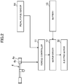
- An output signal of the accelerator sensor 4b is fed into a vehicle controller 11.
- the vehicle controller 11 generates an instruction value according to an operation amount of the accelerator grip 4a.
- the motor driver 12 supplies the electric motor 30 with power according to the instruction value.
- the motor driver 12 includes an inverter that converts DC power from the battery 13 into AC power of a frequency according to the instruction value, for example, and then supplies the converted power to the electric motor 30. At this time, the bicycle 1 can be driven only by the power from the electric motor 30.
- the crank shaft 61 includes a sensor 64 (see FIG. 5 ) that detects force (pedal force) applied by a user to the pedals 63 (hereinafter, sensor 64 is referred to as "pedal force sensor").
- the pedal force sensor 64 is a sensor (e.g., magnetorestrictive sensor) that outputs, for example, a signal according to torsion of the crank shaft 61. As shown in FIG. 2 , an output signal of the pedal force sensor 64 is fed into the vehicle controller 11. The vehicle controller 11 generates an instruction value according to the pedal force.
- the motor driver 12 supplies the electric motor 30 with power according to the instruction value, and the electric motor 30 is driven with the supplied power. With the electric motor 30 being driven in this way, a user's pedaling of the pedals 63 is assisted. When the electric motor 30 is not operating, the rear wheel 40 drives only by the rotational force from the crank shaft 61 through the power transmission mechanism.
- the bicycle 1 can be driven in the following three modes: (i) Electric mode (driven only by power of the electric motor 30); (ii) Assisted mode (driven by the electric motor 30 and pedal force applied to the pedals 63; and (iii) Human-powered mode (driven only by pedal force applied to the pedals 63).
- the bicycle 1 may have a switch for a user to switch these three modes.
- the structure and the operations proposed in this disclosure are not limited to be applied to the bicycle that can select these three modes, but may also be applied to a bicycle that can select only (ii) assisted mode and (iii) human-powered mode, for example.
- the bicycle may not include the accelerator grip 4a and the accelerator sensor 4b.
- the drive unit 10 includes two power systems.
- a first power system includes the electric motor 30, and transmits rotation of a rotor 32 included in the electric motor 30 to a hub 41 of the rear wheel 40.
- a second power system includes the crank shaft 61 to which the pedals 63 are attached, and transmits rotation of the crank shaft 61 to the hub 41 of the rear wheel 40.
- the electric motor 30 includes a stator 31 and a rotor 32.
- the stator 31 includes a plurality of iron cores, which are arranged in a circular manner around the rotation center Ax1 of the rear wheel 40, and coils wound around the iron cores.
- the rotor 32 includes a plurality of magnets arranged in a circular manner around the rotation center Ax1 of the rear wheel 40, and is rotatable around the rotation center Ax1.
- the rotor 32 of the bicycle 1 is located radially outward of the stator 31, and radially opposed to the stator 31. That is, the electric motor 30 is a radial gap electric motor.
- the electric motor 30 may be an axial gap electric motor.
- the rotor 32 and the stator 31 may be opposed to each other in the axial direction (the direction of the rotation center Ax1).
- the rear wheel 40 includes a rim 43 to which a tire 44 is attached, and the hub 41.
- the rear wheel 40 also includes a spoke 45 radially extending from the hub 41 and supporting the rim 43.
- the rotor (magnet) 32 is fixed to the inner surface of the rear hub 41, and the rotor 32 rotates integrally with the rear hub 41.
- the front part of the drive unit 10 includes the crank shaft 61 to which the pedals 63 are attached.
- a gear 65 (bevel gear in the exampled bicycle 1), which integrally rotates with the crank shaft 61, and the pedal force sensor 64 described above are disposed on the crank shaft 61.
- the transmission shaft 21 is located at the rotation center Ax1 of the rear wheel 40.
- the rear part of the rear arm 50 includes an arm rear part 51, and the transmission shaft 21 is rotatably supported by the arm rear part 51.
- the second power system includes the power transmission mechanism for transmitting the power (rotational force) of the crank shaft 61 to the transmission shaft 21.
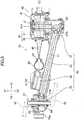
- the power transmission mechanism is a shaft drive mechanism. That is, as shown in FIG. 5 , the power transmission mechanism includes the gear 65 provided on the crank shaft 61, a gear 26 (specifically, bevel gear) provided on the transmission shaft 21, and a transmission shaft 27 arranged in the front-rear direction of the vehicle body when viewed from the side of the vehicle (in the following, the transmission shaft 21 is referred to as "first transmission shaft”, and the transmission shaft 27 is referred to as "second transmission shaft”).
- the front end of the second transmission shaft 27 includes a gear 27A (specifically, bevel gear) that is engaged with the gear 65 on the crank shaft 61.
- the rear end of the second transmission shaft 27 includes a gear 27B (specifically, bevel gear) that is engaged with the gear 26 on the first transmission shaft 21.
- the drive unit 10 may include a chain drive mechanism and a belt drive mechanism as the power transmission mechanism.
- the bicycle 1 may include a chain and a belt instead of the second transmission shaft 27.
- the first transmission shaft 21 is coupled to the rear hub 41.
- the first transmission shaft 21 is coupled to the rear hub 41 through a one-way clutch 23 (see FIG. 6 ).
- the one-way clutch 23 transmits the rotational force of the first transmission shaft 21 to the rear hub 41, but does not transmit the rotational force of the rear hub 41 to the first transmission shaft 21.
- the supporting structure of the first transmission shaft 21 and the location of the one-way clutch 23 will be described later in detail.
- the rear arm 50 is disposed either rightward or leftward of the rear wheel 40 and the electric motor 30, and not disposed on the other.
- the exampled drive unit 10 as shown in FIG. 5 , there is a rear arm 50 on the left side of the rear wheel 40, and there is no rear arm on the right side.
- a maintenance operator can easily access the rear wheel 40 and the electric motor 30, and this improves the workability of the maintenance operation.
- the operator can easily detach a right wall 41B of the rear hub 41.
- the rear arm 50 may be disposed only rightward of the rear wheel 40.
- the power transmission mechanism that transmits the rotation of the crank shaft 61 to the first transmission shaft 21 is disposed together with the rear arm 50 leftward of the rear wheel 40 and the electric motor 30.
- the second transmission shaft 27 is disposed on the same side as the rear arm 50 with respect to the center C1 of the rear wheel 40 in the left-right direction. Accordingly, the power transmission mechanism is coupled to the left part of the first transmission shaft 21.
- the stator 31 is supported by the rear part 51 (hereinafter referred to as arm rear part) of the rear arm 50.
- the arm rear part 51 is located leftward of the stator 31.
- the first transmission shaft 21 extends rightward from the arm rear part 51 side, and is disposed radially inward of the stator 31.
- the first transmission shaft 21 is coupled to the rear hub 41, on the opposite side (i.e., on the right) to the power transmission mechanism and the rear arm 50 across the center C1 of the electric motor 30 in the left-right direction.
- the first transmission shaft 21 is coupled to the right wall 41B (see FIG. 6 ) of the rear hub 41. This structure allows the rear arm 50 located only leftward to support the electric motor 30 and the power transmission from the crank shaft 61 to the rear hub 41.
- the front part of the rear arm 50 includes the front housing 56 holding the crank 60.
- the rear arm 50 includes the shaft case 53 formed like a tube and extending from the front housing 56 rearward.
- the second transmission shaft 27 is accommodated in the shaft case 53, and rotatably held by a bearing provided to the shaft case 53.
- the gear 27A at the front end of the second transmission shaft 27 is located inside the front housing 56.
- the gear 27B at the rear end of the second transmission shaft 27 is accommodated in a housing 51A of the arm rear part 51 described later.
- the housing 51A is located leftward away from the center C1 of the rear wheel 40 in the left-right direction (that is, the center of the vehicle in the left-right direction).
- the shaft case 53 extends obliquely frontward from the housing 51A toward the center C1.
- the front end of the shaft case 53 is located in front of the rear wheel 40 or the electric motor 30.
- the bicycle 1 may employ a chain drive mechanism or a belt drive mechanism as the power transmission mechanism.
- the rear arm 50 may include a case instead of the shaft case 53 so as to accommodate the chain or the belt.
- the bicycle 1 may not include a case for accommodating the power transmission mechanism.
- the arm rear part 51 of the rear arm 50 is connected to the rear end of the shaft case 53 (see FIG. 5 ).
- the arm rear part 51 includes the housing 51A described above.
- the housing 51A is connected to the rear end of the shaft case 53.
- the arm rear part 51 includes a front cover 51E that has an opening, to which the rear end of the shaft case 53 is fitted, and is fixed to the rear end of the shaft case 53.
- the housing 51A is fixed to the front cover 51E by a fixture such as a screw, thereby forming an accommodation part for accommodating the gears 27B and 26.
- the housing 51A can protect the power transmission mechanism (specifically, gears 27B and 26).
- the structure for connecting the arm rear part 51 to the shaft case 53 is not limited to the example of the bicycle 1, and may be varied as appropriate.
- the drive unit 10 includes a supporting shaft B that supports the electric motor 30 and the rear wheel 40.
- the supporting shaft B extends rightward from the arm rear part 51.
- the supporting shaft B is a tube-like member arranged along the rotation center Ax1 of the rear wheel 40 and the electric motor 30, and is not rotatable.
- the first transmission shaft 21, which transmits the rotational force of the crank shaft 61 to the rear hub 41, is disposed inside the supporting shaft B.
- the supporting shaft B supports the rear hub 41 through the bearings 49A and 49B, and thus allows rotation of the rear wheel 40.
- the layout of the bearings 49A and 49B will be described later in detail.
- the supporting shaft B is composed of two members fixed to each other.
- the supporting shaft B includes a shaft body 51B and a connected shaft 51C.
- Each of the shaft body 51B and the connected shaft 51C is a tube-like members, and those are fixed to each other in the axial direction.
- the supporting shaft B can be divided in the axial direction.
- the stator 31 of the electric motor 30 is fixed to the outer peripheral surface of the connected shaft 51C.
- the iron cores constituting the stator 31 are welded or bonded to the outer peripheral surface of the connected shaft 51C.
- the connected shaft 51C is employed as a holder for the stator 31.
- the shaft body 51B is integrally formed with the housing 51A.
- the connected shaft 51C is located rightward of the shaft body 51B, and fixed to the shaft body 51B by a fixture, such as a screw 59 (see FIG. 7 ) and a bolt.
- a fixture such as a screw 59 (see FIG. 7 ) and a bolt.
- the screw 59 is located radially inward of the stator 31.
- the supporting shaft B is constituted by two members (that is, the shaft body 51B and the connected shaft 51C) in this way, and this enhances ease of assembly of the drive unit 10.
- the configuration of the supporting shaft B is not limited to the example of the drive unit 10.
- the shaft body 51B and the connected shaft 51C of the supporting shaft B may be integrally formed.
- a stator may be fitted outside of the supporting shaft B, and the inner periphery of the stator may be fixed to the outer peripheral surface of the supporting shaft B.
- the shaft body 51B and the housing 51A may be separately formed.
- the shaft body 51B and the housing 51A may be fixed to each other by a fixture, such as a screw.
- the rear hub 41 includes a right wall 41B and a left wall 41A.
- the right wall 41B is located rightward of the center C1 (center of the electric motor 30) of the rear wheel 40 in the left-right direction, and covers the right side of the electric motor 30.
- the left wall 41A is located leftward of the center C1 of the rear wheel 40, and covers the left side of the electric motor 30.
- the rear hub 41 includes a middle wall 41C formed into a cylindrical shape and located between the right wall 41B and the left wall 41A.
- the middle wall 41C covers the outer peripheral surface of the electric motor 30.
- the rotor (magnet) 32 described above is fixed to the inner surface of the middle wall 41C. As shown in FIG.
- the outer circumference of the right wall 41B is fixed to the middle wall 41C by a fixture, such as a screw 42 or a bolt.
- the outer circumference of the left wall 41A is fixed to the middle wall 41C by a fixture, such as a screw 42 or a bolt.
- the configuration of the rear hub 41 is not limited to the example of the bicycle 1.
- the rear hub 41 may be formed of two members.
- the left wall 41A (or the right wall 41B) and the middle wall 41C may be integrally formed.
- an opening 41a that opens in the axial direction is formed on the left wall 41A.
- the supporting shaft B and the first transmission shaft 21 are disposed inside of the opening 41a. That is, the supporting shaft B and the first transmission shaft 21 extend through the opening 41a from the inside of the rear hub 41 to the outside of the rear hub 41.
- the rear arm 50 is disposed only leftward of the rear wheel 40.
- the right wall 41B of the rear hub 41 does not have an opening through which the supporting shaft B and the first transmission shaft 21 are routed.
- the rear hub 41 is supported through a left bearing 49A and a right bearing 49B, which are spaced apart from each other in the left-right direction.
- the two bearings 49A and 49B are opposed to each other in the left-right direction across the center C1 of the rear wheel 40.
- the left bearing 49A is disposed between the inner peripheral surface of the opening 41a of the left wall 41A and the outer peripheral surface of the supporting shaft B (more specifically, shaft body 51B).
- the right bearing 49B is disposed between the right wall 41B of the rear hub 41 and the outer peripheral surface of the supporting shaft B (more specifically, connected shaft 51C).
- a supported portion 41b projecting in the axial direction (leftward in the exampled drive unit 10) is formed on the inner surface of the right wall 41B.
- the supported portion 41b is annular when viewed in the axial direction.
- the right bearing 49B is disposed between the inner peripheral surface of the supported portion 41b and the outer peripheral surface of the connected shaft 51C.
- the supporting shaft B supports the rear hub 41 through the bearings 49A and 49B, and allows rotation of the rear hub 41.
- the structure for supporting the rear hub 41 is not limited to the example of the drive unit 10.
- the supported portion 41b of the right wall 41B may be located inside of the end part of the tube-like supporting shaft B.
- the right bearing 49B may be disposed between the outer peripheral surface of the supported portion 41b of the right wall 41B and the inner peripheral surface of the supporting shaft B.
- the width of the left bearing 49A in the axial direction is wider than the width of the right bearing 49B. This increases durability of the supporting structure of the rear hub 41.
- a seal 48 is disposed between the inner peripheral surface of the opening 41a of the left wall 41Ab and the outer peripheral surface of the supporting shaft B (more specifically, shaft body 51B).
- the seal 48 is located outwardly from the bearing 49A in the axial direction (in the exampled drive unit 10, leftward).
- the shaft body 51B includes a large-diameter part 51f and a small-diameter part 51g, which has a smaller diameter than the large-diameter part 51f.
- the large-diameter part 51f is located radially inward of the left bearing 49A.
- a cable passage (through hole) 51a is formed on the large-diameter part 51f, and an electric cable 33 described later is routed through the cable passage 51a (see FIGs. 4 and 7 ).
- the small-diameter part 51g is located rightward of the large-diameter part 51f, and fixed to the connected shaft 51C.
- the connected shaft 51C to which the stator 31 is fixed, has substantially the same diameter as the small-diameter part 51g.
- a stopper plate 57 is attached to the side surface of the large-diameter part 51f so as to prevent the left bearing 49A from falling out.
- a guide plate 58 is attached to the side surface of the large-diameter part 51f so as to guide a position of an electric wire connected to the stator 31.
- a radially extending flange part 51c is formed at the end of the supporting shaft B (specifically, connected shaft 51C).
- the flange part 51c prevents the right bearing 49B from moving outward in the axial direction (rightward in the example of the drive unit 10).
- the right bearing 49B is fitted outside of the connected shaft 51C, and then the stator 31 is fixed to the outer peripheral surface of the connected shaft 51C.
- the connected shaft 51C is fixed to the shaft body 51B by a fixture, such as the screw 59.
- the structure for preventing the right bearing 49B from falling out is not limited to the example of the drive unit 10.
- the bicycle 1 includes a brake device 71 for the rear wheel 40.
- the brake device 71 is, for example, a disc brake device, and thus includes a brake disc 72, which integrally rotates with the rear hub 41, and calipers 73.
- the brake disc 72 is attached to, for example, the left wall 41A.
- the supporting shaft B and the first transmission shaft 21 are located radially inward of the brake disc 72.
- the calipers 73 are supported by the rear arm 50.
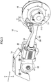
- the calipers 73 are supported by the shaft case 53 through the bracket 53a (see FIG. 3 ).
- the configuration of the brake device 71 is not limited to the example of the drive unit 10.
- the brake device 71 may be a drum brake device. In this case, a brake drum may be attached to the left wall 41A.
- the supporting shaft B and the first transmission shaft 21 project leftward from the opening 41a of the rear hub 41.
- the first transmission shaft 21 extends further leftward than the supporting shaft B, and thus includes a part 21a (hereinafter referred to as connection part) that is located further leftward than the supporting shaft B.
- the connection part 21a is connected to the second transmission shaft 27.
- the connection part 21a is connected to the second transmission shaft 27 through the gears 26 and 27B.
- the gear 26 on the connection part 21a is located further outward (more specifically, leftward) than the gear 27B of the second transmission shaft 27 in the axial direction.
- the first transmission shaft 21 is connected to the rear hub 41, on the opposite side to the rear arm 50 and the power transmission mechanism (in the exampled bicycle 1, second transmission shaft 27 and gears 26 and 27B) across the center C1 of the rear wheel 40 so that power can be transmitted from the first transmission shaft 21 to the rear hub 41.
- the first transmission shaft 21 is connected to a wall part opposite to a wall part where the opening 41a is formed (in the example of the drive unit 10, right wall 41B).
- the first transmission shaft 21 is connected to the right wall 41B through the one-way clutch 23 which allows power to be transmitted to the rear hub 41 and prevents power transmission in the opposite direction.
- a connection part 41c is formed on the inner surface of the right wall 41B.
- the connection part 41c projects from the inner surface of the right wall 41B in the axial direction, and is annular when viewed in the axial direction.
- the connection part 41c is located radially inward of the end of the supporting shaft B (specifically, connected shaft 51C).
- the end (right end) of the first transmission shaft 21 is located radially inward of the connection part 41c.
- the one-way clutch 23 is disposed between the inner peripheral surface of the connection part 41c and the outer peripheral surface of the transmission shaft 21.
- the one-way clutch 23 is located downstream of the second transmission shaft 27 in the power transmission path extending from the crank shaft 61 to the rear hub 41.
- the one-way clutch 23 is located downstream of the first transmission shaft 21 in the power transmission path. As such, when the bicycle 1 is running only by the power of the electric motor 30, not only the rotation of second transmission shaft 27 but also the rotation of the first transmission shaft 21 is not generated.
- the location of the one-way clutch 23 is not limited to the example of the drive unit 10.
- the first transmission shaft 21 may be formed of two members that are connected to each other in the axial direction, and the one-way clutch 23 may be disposed between the two members.
- the one-way clutch 23 may be disposed between the first transmission shaft 21 and the gear 26 on the first transmission shaft 21, or between the second transmission shaft 27 and the gear 27B on the second transmission shaft 27.
- the supporting shaft B is not rotatable, while the first transmission shaft 21 disposed inside of the supporting shaft B is rotatable.
- the first transmission shaft 21 is rotatably supported through the bearings 47A and 47B that are spaced apart from each other in the left-right direction.
- the bearings 47A and 47B are respectively disposed at the left end and the right end of the first transmission shaft 21. That is, the first transmission shaft 21 is rotatably supported at the opposite ends thereof.
- Such placement of the bearings 47A and 47B can improve stability of supporting the first transmission shaft 21. For example, deformation of the first transmission shaft 21 can be effectively prevented compared to the structure of disposing the bearings 47A and 47B at the center of the first transmission shaft 21 and supporting the first transmission shaft 21 by the supporting shaft B.
- the right bearing 47B is disposed between the inner peripheral surface of the connection part 41c of the rear hub 41 and the outer peripheral surface of the first transmission shaft 21. As such, clearance between the inner peripheral surface of the connection part 41c and the outer peripheral surface of the first transmission shaft 21 (clearance in which the one-way clutch 23 is disposed) can be maintained by the bearing 47B with high accuracy.
- the bearing 47B is located further outward (specifically, rightward) than the one-way clutch 23 in the axial direction.
- the arm rear part 51 of the rear arm 50 is located outward of the first transmission shaft 21 in the axial direction (leftward in the exampled drive unit 10), and includes a left cover 51D for covering the housing 51A.
- the left bearing 47A is held inside of the left cover 51D.
- a recess is formed on the inner surface of the left cover 51D, and the bearing 47A is fitted into the recess.
- the bearing 47A is located further outward than the gear 26 of the first transmission shaft 21 in the axial direction (specifically, leftward). This prevents the first transmission shaft 21 from being deformed, and enables to highly accurately maintain the relative positions of the gear 26 on the first transmission shaft 21 and the gear 27B on the transmission shaft 27.
- the left end of the first transmission shaft 21 is supported by the arm rear part 51 through the bearing 47A.
- the right end of the first transmission shaft 21 is supported by the right wall 41B of the rear hub 41 through the bearing 47B.
- the right wall 41B of the rear hub 41 is supported by the supporting shaft B of the rear arm 50, and thus the right end of the first transmission shaft 21 is indirectly supported by the supporting shaft B.
- the supporting structure of the first transmission shaft 21 is not limited to the example of the drive unit 10.
- one or both of the bearings 47A and 47B may be located inside of the supporting shaft B to support the first transmission shaft 21. That is, one or both of the bearings 47A and 47B may be disposed between the inner peripheral surface of the supporting shaft B and the outer peripheral surface of the first transmission shaft 21.
- the first transmission shaft 21 includes the connection part 21a that is located further leftward than the supporting shaft B.
- This connection part 21a is located inside of an accommodation part defined by the housing 51A and the left cover 51D. This structure can prevent external dusts and moisture from entering the interior of the rear hub 41 through the clearance between the inner peripheral surface of the supporting shaft B and the outer peripheral surface of the first transmission shaft 21.
- the drive unit 10 includes the electric cable 33.
- the electric cable 33 includes an electric wire connected to the stator 31, and an electric wire connected to an encoder that detects rotational speed of the electric motor 30.
- the annular guide plate 58 is disposed inside of the rear hub 41 so as to guide the position of the electric cable 33.
- the electric cable 33 is located between the guide plate 58 and the small-diameter part 51g of the supporting shaft B (shaft body 51B).
- the electric cable 33 is routed radially inward of the left bearing 49A, and extends from inside to outside of the rear hub 41. This configuration allows the electric cable 33 to extend toward the rear arm 50.
- the electric cable 33 is arranged along the rear arm 50, and the ends of the electric wire included in the electric cable 33 are connected to the motor driver 12 and/or the vehicle controller 11 (see FIG. 2 ).
- the cable passage 51a through which the electric cable 33 is routed, is formed on the supporting shaft B.
- the cable passage 51a allows communication between the interior of the rear hub 41 and the interior of the housing 51A. That is, the cable passage 51a is not in communication with the exterior of the vehicle, but in communication with the interior of the housing 51A. This prevents external dusts and moisture from entering the interior of the rear hub 41 through the cable passage 51a.
- the supporting shaft B includes a hole penetrating the supporting shaft B in the axial direction. This through hole functions as the cable passage 51a.
- the supporting shaft B includes the shaft body 51B and the connected shaft 51C that are connected to each other in the axial direction.
- the large-diameter part 51f of the shaft body 51B has a diameter larger than the small-diameter part 51g and the connected shaft 51C, and the right side surface of the shaft body 51B is exposed inside the rear hub 41.
- the cable passage 51a is formed on the right side surface of the shaft body 51B.
- the cable passage 51a is disposed above the first transmission shaft 21, for example.
- the configuration of the cable passage 51a is not limited to the example of the drive unit 10.
- a groove may be formed on the outer peripheral surface of the supporting shaft B (specifically, on the outer peripheral surface of large-diameter part 51f of shaft body 51B).
- Such a groove may be used as the cable passage 51a.
- the electric cable 33 is disposed radially inside the left bearing 49A.
- an annular member (collar) may be disposed radially between the outer peripheral surface of the shaft body 51B and the left bearing 49A.
- a through hole may be formed on the annular member to function as the cable passage 51a.
- the electric cable 33 is routed through the housing 51A, and, as shown in FIG. 3 , extends forward along the rear arm 50 (more specifically, along the shaft case 53).
- the wall (front cover 51E, see FIG. 3 ) on the front side of the housing 51A has a through hole 51e (see FIG. 7 ) penetrating through the wall.
- the electric cable 33 is routed through the through hole 51e, and extends forward from the interior of the housing 51A.
- the through hole 51e is located, for example, above the gear 27B of the second transmission shaft 27.
- a cable guide 52 may be disposed inside the housing 51A.
- the cable guide 52 guides the position of the electric cable 33 in the interior of the housing 51A.
- the cable guide 52 is disposed so as to prevent interference between the gears 26 and 27B, which are disposed inside the housing part 51A, and the electric cable 33.
- the cable guide 52 is disposed above and rightward of the gear 26, and above the gear 27B.
- the drive unit 10 includes the motor driver 12 (see FIG. 2 ) having the inverter and supplying power stored in the battery 13 to the electric motor 30.
- the motor driver 12 is supported by the rear arm 50.
- the rear arm 50 includes the auxiliary housing 55, and the auxiliary housing 55 accommodates the motor driver 12. This placement of the motor driver 12 can shorten the length of the power supplying electric wire extending from the battery 13 to the electric motor 30.
- the auxiliary housing 55 also accommodates the vehicle controller 11, which calculates an instruction value to the motor driver 12.
- the auxiliary housing 55 is located between the crank shaft 61 and the first transmission shaft 21.
- the auxiliary housing 55 is disposed in front of the rear wheel 40, and at least a part of the auxiliary housing 55 overlaps with the rear wheel 40 in the front view of the vehicle.
- the auxiliary housing 55 is located behind the crank shaft 61, and at least a part of the auxiliary housing 55 overlaps with the crank shaft 61 in the front view of the vehicle. The placement of the auxiliary housing 55 can prevent an external object from colliding with the auxiliary housing 55.
- the auxiliary housing 55 includes a left housing 55A and a right housing 55B that are combined with each other in the left-right direction.
- the left housing 55A has a box-like shape with the right side open
- the right housing 55B has a box-like shape with the left side open.
- the left housing 55A is attached to the rear arm 50.
- the shaft case 53 penetrates the left housing 55A in the front-rear direction.
- the front housing 56 is disposed in front of the left housing 55A, and the left housing 55A is fixed to the front housing 56.
- the motor driver 12 and the vehicle controller 11 are attached to the interior of the right housing 55B. Cooling fins 55a may be formed on the outer surface of the right housing 55B.
- the position of the auxiliary housing 55 and the structure of attaching the auxiliary housing 55 to the rear arm 50 are not limited to the examples of the drive unit 10.
- the right housing 55B may be attached to the shaft case 53
- the left housing 55A may be attached to the right housing 55B.
- the motor driver 12 and the vehicle controller 11 may be fixed to the left housing 55A.
- the auxiliary housing 55 may be formed of two members that are combined with each other in the front-rear direction.
- the auxiliary housing 55 may be attached to the outer surface of the shaft case 53.
- the electric cable 33 may be routed through the interior of the shaft case 53.
- the auxiliary housing 55 has an opening 55b (hereinafter referred to as "cable opening") located above shaft case 53.
- the electric cable 33 enters into the auxiliary housing 55 through the cable opening 55b.
- the cable opening 55b is formed on the left housing 55A, and the electric cable 33 is located above the shaft case 53. This prevents interference between the electric cable 33 and the rear wheel 40 and between the electric cable 33 and an obstacle on the path of the bicycle 1.
- the electric cable 33 enters from the cable opening 55b into the auxiliary housing 55, curves rightward, and extends to the motor driver 12 described above.
- the auxiliary housing 55 includes a guide wall 55c therein to prevent interference between the electric cable 33 and the shaft case 53.
- a through hole 55d is formed on a wall in front of the auxiliary housing 55.
- the auxiliary housing 55 is in communication with the interior of the front housing 56 through the through hole 55d and a through hole 56d (see FIG. 8 ) formed on the front housing 56.
- the electric wire connected to the pedal force sensor 64 is connected to the vehicle controller 11 inside the auxiliary housing 55 though the through holes 55d and 56d.
- the front part of the rear arm 50 includes the front housing 56 accommodating the gear 65 and the pedal force sensor 64, for example.
- the front housing 56 supports the crank shaft 61 through the bearings 66A and 66B, and allows rotation of the crank shaft 61.
- the opposite ends of the crank shaft 61 project from the front housing 56 in the axial direction.
- the pedals 63 are respectively fixed to the opposite ends of the crank shaft 61.
- the front housing 56 accommodates the gear 65 and the pedal force sensor 64 that are disposed on the crank shaft 61 (see FIG. 5 ).
- the front housing 56 is attached to the bracket 7d (see FIG. 1 ) that is provided to the lowest part of the vehicle frame 7.
- the bracket 7d is a box-like member with the bottom side open, for example.
- the front housing 56 is disposed inside the bracket 7d, and attached to the bracket 7d.
- the front housing 56 includes a front connection part 56a and a rear connection part 56b, which extend upward and are apart from each other in the front-rear direction.
- a fixture 8 specifically, bolt, see FIG. 8
- a fixture 8 is inserted into the connection parts 56a and 56b and the bracket 7d in the left-right direction, and thus the connection parts 56a and 56b are fixed to the bracket 7d.
- the front housing 56 may be attached to the bracket 7d through a damper.
- a damper 56c is attached to the rear connection part 56b ,and is vertically sandwiched by the rear connection part 56b and the bracket 7d.
- the connection part 56b is attached to the bracket 7d so as to be slightly and vertically movable to the bracket 7d.
- the rear arm 50 is vertically movable around the fixture (specifically, bolt) inserted into the front connection part 56a, and the damper 56c dampens the vertical movement of the rear arm 50.
- the structures of attaching the front housing 56 to the vehicle frame 7 may not be limited to the example of the drive unit 10, but may be varied as appropriate.
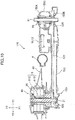
- FIG. 9 is a diagram showing an example of the drive unit including a chain drive mechanism as a power transmission mechanism for transmitting rotational force from the crank shaft 61 to the first transmission shaft 21.
- FIG. 10 is a cross sectional view of the drive unit taken along the line X-X in FIG. 9 .
- the drive unit 110 includes, as the power transmission mechanism, a sprocket 125 disposed on the crank shaft 61, a sprocket 126 disposed on the transmission shaft 21, and a transmission chain 127 engaged by the sprocket 125 and the sprocket 126.
- the drive unit 110 may include a tension mechanism 129 (see FIG. 9 ) that prevents deformation of the transmission chain 127.
- a rear arm 150 and the transmission chain 127 are disposed rightward of the rear wheel 40 in the drive unit 110.
- the supporting shaft B includes the shaft body 51B and the connected shaft 51C. In the drive unit 110, the shaft body 51B is disposed rightward of the connected shaft 51C, and fixed to the connected shaft 51C.
- the rear arm 150 includes an arm rear part 151 including the supporting shaft B, a front housing 156 accommodating the pedal force sensor 64, and an auxiliary housing 155 accommodating the motor driver 12 and the vehicle controller 11.
- the rear arm 150 includes a chain accommodation part D accommodating the transmission chain 127.
- the front part of the chain accommodation part D, the front housing 156, and the auxiliary housing 155 are formed by three members that are coupled together in the left-right direction. That is, the front part of the rear arm 150 includes a left cover 150A, a right cover 150B, and a partition plate 150C.
- the front housing 156 and the auxiliary housing 155 are defined by the left cover 150A and the partition plate 150C.
- the motor driver 12 and the vehicle controller 11 are fixed to the left cover 150B.
- the front part of the chain accommodation part D is defined by the right cover 150B and the partition plate 150C.
- the rear arm 150 includes a tube-like chain case 153 for connecting the housing 151A of the arm rear part 151 to the front part of the rear arm 150 and forming the chain accommodation part D.
- the drive unit 110 may use a belt drive mechanism as the power transmission mechanism. That is, the drive unit 110 may include a pulley fixed to the crank shaft 61, a pulley fixed to the transmission shaft 21, and a belt engaged by these two pulleys.
- the bicycle may have only the assisted mode and the human-powered mode, and not have the electric mode in which the bicycle runs only by power of the electric motor 30. In this case, the bicycle may not have the accelerator grip 4a and the accelerator sensor 4b.
- the rear hub 41 may not include the left wall 41A.
- the middle wall 41C may be supported by the left bearing 49A.
Landscapes
- Engineering & Computer Science (AREA)
- Chemical & Material Sciences (AREA)
- Combustion & Propulsion (AREA)
- Transportation (AREA)
- Mechanical Engineering (AREA)
- Electric Propulsion And Braking For Vehicles (AREA)
- Connection Of Motors, Electrical Generators, Mechanical Devices, And The Like (AREA)
- Axle Suspensions And Sidecars For Cycles (AREA)
Claims (15)
- Eine Antriebs-Einheit (10), die umfasst:eine hintere Nabe (41), die an einem Hinter-Rad (40) vorgesehen ist;einen hinteren Arm (50);ein erstes Leistungs-System, das einen Elektro-Motor (30) enthält, der Elektro-Motor (30) in dem Hinter-Rad (40) untergebracht ist und einen Rotor (32) und einen Stator (31) enthält, das erste Leistungs-System konfiguriert ist, um Drehung des Rotors (32) auf die hintere Nabe (41) zu übertragen; undein zweites Leistungs-System, das eine Kurbel-Welle (61) hat, mit Pedalen (63), die daran befestigt sind, und konfiguriert ist, um die Drehung der Kurbel-Welle (61) auf die hintere Nabe (41) zu übertragen,wobeidas zweite Leistungs-System einen Leistungs-Übertragungs-Mechanismus (27, 26) enthält, das zweite Leistungs-System ist konfiguriert, um die Drehung der Kurbel-Welle (61) über den Leistungs-Übertragungs-Mechanismus (27, 26) auf die hintere Nabe (41) zu übertragen,der hintere Arm (50) und der Leistungs-Übertragungs-Mechanismus (27, 26) sind in einer ersten Richtung positioniert, die eine von einer rechten Richtung und einer linken Richtung ist, in Bezug auf ein Zentrum (C1) des Hinter-Rades (40) in einer Links-Rechts-Richtung,dadurch gekennzeichnet, dassdas zweite Leistungs-System eine Übertragungs-Welle (21) und den Leistungs-Übertragungs-Mechanismus (27, 26) beinhaltet, die Übertragungs-Welle (21) drehbar ist und radial innerhalb des Stators (31) angeordnet ist, der Leistungs-Übertragungs-Mechanismus (27, 26) die Kurbel-Welle (61) mit der Übertragungs-Welle (21) koppelt, das zweite Leistungs-System konfiguriert ist, um die Drehung der Kurbel-Welle (61) über den Leistungs-Übertragungs-Mechanismus (27, 26) und die Übertragungs-Welle (21) auf die hintere Nabe (41) zu übertragen, wobei die Übertragungs-Welle (21) mit der hinteren Nabe (41) an einer Position in einer zweiten Richtung gekoppelt ist, die eine der ersten Richtung entgegengesetzte Richtung ist, in Bezug auf die Mitte (C1) des Hinter-Rads (40) in der Links-Rechts-Richtung.
- Die Antriebs-Einheit (10) gemäß Anspruch 1, gekennzeichnet durch eine Lagerungs-Welle (B), die wie ein Rohr ausgebildet ist, das sich von einem hinteren Teil des hinteren Arms (50) in die zweite Richtung erstreckt, wobei
die Übertragungs-Welle (21) radial innerhalb der Lagerungs-Welle (B) angeordnet ist, und der Stator (31) radial außen von der Lagerungs-Welle (B) fixiert ist. - Die Antriebs-Einheit (10) gemäß Anspruch 2, dadurch gekennzeichnet, dass die hintere Nabe (41) eine erste Wand (41A), die in der ersten Richtung liegt, und eine zweite Wand (41B), die in der zweiten Richtung liegt, beinhaltet, und
die Übertragungs-Welle (21) und die Lagerungs-Welle (B) sich in der zweiten Richtung, durch eine Öffnung (41a), die an der ersten Wand (41A) ausgebildet ist erstrecken und mit der zweiten Wand (41B) gekoppelt sind. - Die Antriebs-Einheit (10) gemäß Anspruch 2, dadurch gekennzeichnet, dass die hintere Nabe (41) drehbar auf der Lagerungs-Welle (B) gelagert ist.
- Die Antriebs-Einheit (10) gemäß Anspruch 4, dadurch gekennzeichnet, dass erste Lager (49A, 49B) radial außen von der Lagerungs-Welle (B) angebracht sind, und die hintere Nabe (41) durch die Lagerungs-Welle (B) über die ersten Lager (49A, 49B) drehbar gelagert ist.
- Die Antriebs-Einheit (10) gemäß Anspruch 5, dadurch gekennzeichnet, dass das erste Lager (49A) in der ersten Richtung in Bezug auf die Mitte (C1) des Hinter-Rades (40) angeordnet ist,
das zweite Lager (49B) in der zweiten Richtung in Bezug auf die Mitte (C1) des Hinter-Rades (40) angeordnet ist, und
die hintere Nabe (41) durch die Lagerungs-Welle (B) durch das zweite Lager (49B) drehbar gelagert ist. - Die Antriebs-Einheit (10) gemäß irgendeinem der Ansprüche 1 bis 6, dadurch gekennzeichnet, dass eine Einweg-Kupplung (23) in dem Leistungs-ÜbertragungsWeg, der sich von der Kurbel-Welle (61) zur hinteren Nabe (41) erstreckt, angeordnet ist, die Einweg-Kupplung (23) lässt eine Übertragung von Drehkraft von der Kurbel-Welle (61) auf die hintere Nabe (41) zu, und verhindert eine Übertragung von Drehkraft von der hinteren Nabe (41) auf die Kurbel-Welle (61).
- Die Antriebs-Einheit (10) gemäß Anspruch 7, dadurch gekennzeichnet, dass die Einweg-Kupplung (23) stromabwärts des Leistungs-Übertragungs-Mechanismus (27, 26) angeordnet ist.
- Die Antriebs-Einheit (10) gemäß Anspruch 7, dadurch gekennzeichnet, dass die Einweg-Kupplung (23) zwischen der Übertragungs-Welle (21) und der hinteren Nabe (41) angeordnet ist.
- Die Antriebs-Einheit (10) gemäß Anspruch 5, dadurch gekennzeichnet, dass ein Elektro-Kabel, das mit dem Stator (31) verbunden ist, radial nach innen zum ersten Lager (49A) geführt ist.
- Die Antriebs-Einheit (10) gemäß irgendeinem der Ansprüche 2 bis 6, dadurch gekennzeichnet, daß ein Pfad (51a), durch den das Elektro-Kabel, das mit dem Stator (31) verbunden ist, geführt ist, in der Lagerungs-Welle (B) ausgebildet ist.
- Die Antriebs-Einheit (10) gemäß irgendeinem der Ansprüche 1 bis 11, dadurch gekennzeichnet, dass die Übertragungs-Welle (21) an gegenüberliegenden Enden drehbar gelagert ist.
- Die Antriebs-Einheit (10) gemäß irgendeinem der Ansprüche 1 bis 12, dadurch gekennzeichnet, dass die Übertragungs-Welle (21) eine erste Übertragungs-Welle ist, und
der Leistungs-Übertragungs-Mechanismus (27, 26) eine zweite Übertragungs-Welle (27) beinhaltet, die Leistung von der Kurbel-Welle (61) auf die erste Übertragungs-Welle (21) überträgt. - Die Antriebs-Einheit (10) gemäß irgendeinem der Ansprüche 1 bis 13, gekennzeichnet durch einen Motor-Treiber (12), der den Elektro-Motor (30) mit elektrischem Strom versorgt, wobei
der Motor-Treiber (12) durch den hinteren Arm (50) gelagert ist. - Ein Fahrrad (1), das die Antriebs-Einheit (10) gemäß irgendeinem der Ansprüche 1 bis 14 umfasst.
Applications Claiming Priority (1)
| Application Number | Priority Date | Filing Date | Title |
|---|---|---|---|
| JP2018142327A JP6633148B1 (ja) | 2018-07-30 | 2018-07-30 | 自転車と、自転車の駆動ユニット |
Publications (2)
| Publication Number | Publication Date |
|---|---|
| EP3604105A1 EP3604105A1 (de) | 2020-02-05 |
| EP3604105B1 true EP3604105B1 (de) | 2021-03-31 |
Family
ID=67513336
Family Applications (1)
| Application Number | Title | Priority Date | Filing Date |
|---|---|---|---|
| EP19188735.5A Active EP3604105B1 (de) | 2018-07-30 | 2019-07-29 | Fahrrad mit einem elektromotor und antriebseinheit des fahrrades |
Country Status (3)
| Country | Link |
|---|---|
| EP (1) | EP3604105B1 (de) |
| JP (1) | JP6633148B1 (de) |
| CN (1) | CN110775193B (de) |
Cited By (1)
| Publication number | Priority date | Publication date | Assignee | Title |
|---|---|---|---|---|
| WO2025016755A1 (de) * | 2023-07-17 | 2025-01-23 | KILLWATT GmbH | Fortbewegungsmittel mit verbesserter anbindung einer antriebseinheit an ein laufrad |
Families Citing this family (1)
| Publication number | Priority date | Publication date | Assignee | Title |
|---|---|---|---|---|
| JP7221327B2 (ja) * | 2021-04-15 | 2023-02-13 | ヤマハ発動機株式会社 | 電動モータを有している自転車及びその駆動ユニット |
Family Cites Families (10)
| Publication number | Priority date | Publication date | Assignee | Title |
|---|---|---|---|---|
| DE9316748U1 (de) * | 1993-11-03 | 1994-03-31 | Metzinger, Arnold, 82239 Alling | Fahrrad mit Gangschaltung |
| JPH1159555A (ja) * | 1997-08-14 | 1999-03-02 | Sony Corp | シャフト駆動式移動装置 |
| CN1078765C (zh) * | 1999-05-04 | 2002-01-30 | 李宜和 | 改良结构的辅助动力电动机 |
| CN2551569Y (zh) * | 2002-06-07 | 2003-05-21 | 陈锡爵 | 改进的自行车传动装置 |
| GB2400084A (en) * | 2003-03-31 | 2004-10-06 | Karbon Kinetics Ltd | Bicycle hub assembly |
| CN2628411Y (zh) * | 2003-07-18 | 2004-07-28 | 陈纯增 | 变速齿轮传动电动助力车 |
| CN201183586Y (zh) * | 2007-12-21 | 2009-01-21 | 包进 | 两轮车的双动力装置 |
| ITMO20130111A1 (it) * | 2013-04-23 | 2014-10-24 | C R D Ct Ricerche Ducati Trent O S R L | Ruota per biciclette a pedalata assistita |
| JP2014240267A (ja) | 2013-05-14 | 2014-12-25 | ヤマハ発動機株式会社 | 鞍乗型電動車両用の駆動機構、車輪及び電動機、並びに鞍乗型電動車両 |
| CN206664846U (zh) * | 2017-04-20 | 2017-11-24 | 李纪召 | 电动自行车传动装置和配置该装置的电动自行车 |
-
2018
- 2018-07-30 JP JP2018142327A patent/JP6633148B1/ja active Active
-
2019
- 2019-07-29 EP EP19188735.5A patent/EP3604105B1/de active Active
- 2019-07-29 CN CN201910689250.3A patent/CN110775193B/zh active Active
Non-Patent Citations (1)
| Title |
|---|
| None * |
Cited By (1)
| Publication number | Priority date | Publication date | Assignee | Title |
|---|---|---|---|---|
| WO2025016755A1 (de) * | 2023-07-17 | 2025-01-23 | KILLWATT GmbH | Fortbewegungsmittel mit verbesserter anbindung einer antriebseinheit an ein laufrad |
Also Published As
| Publication number | Publication date |
|---|---|
| JP6633148B1 (ja) | 2020-01-22 |
| EP3604105A1 (de) | 2020-02-05 |
| CN110775193A (zh) | 2020-02-11 |
| JP2020019299A (ja) | 2020-02-06 |
| CN110775193B (zh) | 2022-05-13 |
Similar Documents
| Publication | Publication Date | Title |
|---|---|---|
| US10661858B2 (en) | Electric-motor-assisted bicycle | |
| KR101506410B1 (ko) | 전동식 안장형 차량 및 전동 차량의 구동 장치 | |
| JP5914108B2 (ja) | 車両用駆動装置 | |
| EP2436592A1 (de) | Elektrische Fahrradnabeneinheit und elektrisches Fahrrad mit der Nabe | |
| US20130284527A1 (en) | Electric vehicle | |
| JP6169531B2 (ja) | 自転車用駆動ユニット | |
| US8413748B2 (en) | Motor-driven vehicle | |
| JPWO2013077214A1 (ja) | 電動式鞍乗り型車両 | |
| JP2023032166A (ja) | 電動バランスバイク | |
| CN108238206A (zh) | 自行车用驱动单元及具备该驱动单元的自行车用驱动系统 | |
| TWI785125B (zh) | 自行車用驅動單元 | |
| EP3604105A1 (de) | Fahrrad mit einem elektromotor und antriebseinheit des fahrrades | |
| JP2022131727A (ja) | モータユニット及び電動自転車 | |
| JP2021062689A (ja) | 駆動ユニットおよび電動補助自転車 | |
| JP2003127941A (ja) | 電動二輪車のバッテリ脱着構造 | |
| WO2020067268A1 (ja) | 電動車両 | |
| JP4109852B2 (ja) | 電動二輪車のスロットル開度検出装置 | |
| CN112770965B (zh) | 电动车辆 | |
| EP4074589B1 (de) | Antriebseinheit und fahrrad mit antriebseinheit | |
| JP6199933B2 (ja) | 鞍乗型車両 | |
| WO2020067269A1 (ja) | 電動車両 | |
| CN112867668A (zh) | 电动车辆 | |
| JP7076587B2 (ja) | 電動車両 |
Legal Events
| Date | Code | Title | Description |
|---|---|---|---|
| PUAI | Public reference made under article 153(3) epc to a published international application that has entered the european phase |
Free format text: ORIGINAL CODE: 0009012 |
|
| STAA | Information on the status of an ep patent application or granted ep patent |
Free format text: STATUS: REQUEST FOR EXAMINATION WAS MADE |
|
| 17P | Request for examination filed |
Effective date: 20190729 |
|
| AK | Designated contracting states |
Kind code of ref document: A1 Designated state(s): AL AT BE BG CH CY CZ DE DK EE ES FI FR GB GR HR HU IE IS IT LI LT LU LV MC MK MT NL NO PL PT RO RS SE SI SK SM TR |
|
| AX | Request for extension of the european patent |
Extension state: BA ME |
|
| RBV | Designated contracting states (corrected) |
Designated state(s): AL AT BE BG CH CY CZ DE DK EE ES FI FR GB GR HR HU IE IS IT LI LT LU LV MC MK MT NL NO PL PT RO RS SE SI SK SM TR |
|
| REG | Reference to a national code |
Ref country code: DE Ref legal event code: R079 Ref document number: 602019003576 Country of ref document: DE Free format text: PREVIOUS MAIN CLASS: B62M0006650000 Ipc: B62K0025000000 |
|
| RIC1 | Information provided on ipc code assigned before grant |
Ipc: B62M 6/65 20100101ALI20200831BHEP Ipc: B62M 17/00 20060101ALI20200831BHEP Ipc: B62K 25/00 20060101AFI20200831BHEP Ipc: B62M 9/06 20060101ALI20200831BHEP |
|
| GRAP | Despatch of communication of intention to grant a patent |
Free format text: ORIGINAL CODE: EPIDOSNIGR1 |
|
| STAA | Information on the status of an ep patent application or granted ep patent |
Free format text: STATUS: GRANT OF PATENT IS INTENDED |
|
| INTG | Intention to grant announced |
Effective date: 20201022 |
|
| GRAS | Grant fee paid |
Free format text: ORIGINAL CODE: EPIDOSNIGR3 |
|
| GRAA | (expected) grant |
Free format text: ORIGINAL CODE: 0009210 |
|
| STAA | Information on the status of an ep patent application or granted ep patent |
Free format text: STATUS: THE PATENT HAS BEEN GRANTED |
|
| AK | Designated contracting states |
Kind code of ref document: B1 Designated state(s): AL AT BE BG CH CY CZ DE DK EE ES FI FR GB GR HR HU IE IS IT LI LT LU LV MC MK MT NL NO PL PT RO RS SE SI SK SM TR |
|
| REG | Reference to a national code |
Ref country code: GB Ref legal event code: FG4D Ref country code: CH Ref legal event code: EP |
|
| REG | Reference to a national code |
Ref country code: AT Ref legal event code: REF Ref document number: 1376645 Country of ref document: AT Kind code of ref document: T Effective date: 20210415 |
|
| REG | Reference to a national code |
Ref country code: DE Ref legal event code: R096 Ref document number: 602019003576 Country of ref document: DE |
|
| REG | Reference to a national code |
Ref country code: IE Ref legal event code: FG4D |
|
| REG | Reference to a national code |
Ref country code: LT Ref legal event code: MG9D |
|
| PG25 | Lapsed in a contracting state [announced via postgrant information from national office to epo] |
Ref country code: NO Free format text: LAPSE BECAUSE OF FAILURE TO SUBMIT A TRANSLATION OF THE DESCRIPTION OR TO PAY THE FEE WITHIN THE PRESCRIBED TIME-LIMIT Effective date: 20210630 Ref country code: FI Free format text: LAPSE BECAUSE OF FAILURE TO SUBMIT A TRANSLATION OF THE DESCRIPTION OR TO PAY THE FEE WITHIN THE PRESCRIBED TIME-LIMIT Effective date: 20210331 Ref country code: HR Free format text: LAPSE BECAUSE OF FAILURE TO SUBMIT A TRANSLATION OF THE DESCRIPTION OR TO PAY THE FEE WITHIN THE PRESCRIBED TIME-LIMIT Effective date: 20210331 Ref country code: BG Free format text: LAPSE BECAUSE OF FAILURE TO SUBMIT A TRANSLATION OF THE DESCRIPTION OR TO PAY THE FEE WITHIN THE PRESCRIBED TIME-LIMIT Effective date: 20210630 |
|
| PG25 | Lapsed in a contracting state [announced via postgrant information from national office to epo] |
Ref country code: LV Free format text: LAPSE BECAUSE OF FAILURE TO SUBMIT A TRANSLATION OF THE DESCRIPTION OR TO PAY THE FEE WITHIN THE PRESCRIBED TIME-LIMIT Effective date: 20210331 Ref country code: RS Free format text: LAPSE BECAUSE OF FAILURE TO SUBMIT A TRANSLATION OF THE DESCRIPTION OR TO PAY THE FEE WITHIN THE PRESCRIBED TIME-LIMIT Effective date: 20210331 Ref country code: SE Free format text: LAPSE BECAUSE OF FAILURE TO SUBMIT A TRANSLATION OF THE DESCRIPTION OR TO PAY THE FEE WITHIN THE PRESCRIBED TIME-LIMIT Effective date: 20210331 |
|
| REG | Reference to a national code |
Ref country code: NL Ref legal event code: MP Effective date: 20210331 |
|
| REG | Reference to a national code |
Ref country code: AT Ref legal event code: MK05 Ref document number: 1376645 Country of ref document: AT Kind code of ref document: T Effective date: 20210331 |
|
| PG25 | Lapsed in a contracting state [announced via postgrant information from national office to epo] |
Ref country code: NL Free format text: LAPSE BECAUSE OF FAILURE TO SUBMIT A TRANSLATION OF THE DESCRIPTION OR TO PAY THE FEE WITHIN THE PRESCRIBED TIME-LIMIT Effective date: 20210331 Ref country code: SM Free format text: LAPSE BECAUSE OF FAILURE TO SUBMIT A TRANSLATION OF THE DESCRIPTION OR TO PAY THE FEE WITHIN THE PRESCRIBED TIME-LIMIT Effective date: 20210331 Ref country code: AT Free format text: LAPSE BECAUSE OF FAILURE TO SUBMIT A TRANSLATION OF THE DESCRIPTION OR TO PAY THE FEE WITHIN THE PRESCRIBED TIME-LIMIT Effective date: 20210331 Ref country code: EE Free format text: LAPSE BECAUSE OF FAILURE TO SUBMIT A TRANSLATION OF THE DESCRIPTION OR TO PAY THE FEE WITHIN THE PRESCRIBED TIME-LIMIT Effective date: 20210331 Ref country code: CZ Free format text: LAPSE BECAUSE OF FAILURE TO SUBMIT A TRANSLATION OF THE DESCRIPTION OR TO PAY THE FEE WITHIN THE PRESCRIBED TIME-LIMIT Effective date: 20210331 Ref country code: LT Free format text: LAPSE BECAUSE OF FAILURE TO SUBMIT A TRANSLATION OF THE DESCRIPTION OR TO PAY THE FEE WITHIN THE PRESCRIBED TIME-LIMIT Effective date: 20210331 |
|
| PG25 | Lapsed in a contracting state [announced via postgrant information from national office to epo] |
Ref country code: PL Free format text: LAPSE BECAUSE OF FAILURE TO SUBMIT A TRANSLATION OF THE DESCRIPTION OR TO PAY THE FEE WITHIN THE PRESCRIBED TIME-LIMIT Effective date: 20210331 Ref country code: SK Free format text: LAPSE BECAUSE OF FAILURE TO SUBMIT A TRANSLATION OF THE DESCRIPTION OR TO PAY THE FEE WITHIN THE PRESCRIBED TIME-LIMIT Effective date: 20210331 Ref country code: PT Free format text: LAPSE BECAUSE OF FAILURE TO SUBMIT A TRANSLATION OF THE DESCRIPTION OR TO PAY THE FEE WITHIN THE PRESCRIBED TIME-LIMIT Effective date: 20210802 Ref country code: RO Free format text: LAPSE BECAUSE OF FAILURE TO SUBMIT A TRANSLATION OF THE DESCRIPTION OR TO PAY THE FEE WITHIN THE PRESCRIBED TIME-LIMIT Effective date: 20210331 Ref country code: IS Free format text: LAPSE BECAUSE OF FAILURE TO SUBMIT A TRANSLATION OF THE DESCRIPTION OR TO PAY THE FEE WITHIN THE PRESCRIBED TIME-LIMIT Effective date: 20210731 |
|
| REG | Reference to a national code |
Ref country code: DE Ref legal event code: R097 Ref document number: 602019003576 Country of ref document: DE |
|
| PG25 | Lapsed in a contracting state [announced via postgrant information from national office to epo] |
Ref country code: ES Free format text: LAPSE BECAUSE OF FAILURE TO SUBMIT A TRANSLATION OF THE DESCRIPTION OR TO PAY THE FEE WITHIN THE PRESCRIBED TIME-LIMIT Effective date: 20210331 Ref country code: AL Free format text: LAPSE BECAUSE OF FAILURE TO SUBMIT A TRANSLATION OF THE DESCRIPTION OR TO PAY THE FEE WITHIN THE PRESCRIBED TIME-LIMIT Effective date: 20210331 Ref country code: DK Free format text: LAPSE BECAUSE OF FAILURE TO SUBMIT A TRANSLATION OF THE DESCRIPTION OR TO PAY THE FEE WITHIN THE PRESCRIBED TIME-LIMIT Effective date: 20210331 |
|
| PLBE | No opposition filed within time limit |
Free format text: ORIGINAL CODE: 0009261 |
|
| STAA | Information on the status of an ep patent application or granted ep patent |
Free format text: STATUS: NO OPPOSITION FILED WITHIN TIME LIMIT |
|
| 26N | No opposition filed |
Effective date: 20220104 |
|
| PG25 | Lapsed in a contracting state [announced via postgrant information from national office to epo] |
Ref country code: MC Free format text: LAPSE BECAUSE OF FAILURE TO SUBMIT A TRANSLATION OF THE DESCRIPTION OR TO PAY THE FEE WITHIN THE PRESCRIBED TIME-LIMIT Effective date: 20210331 |
|
| REG | Reference to a national code |
Ref country code: BE Ref legal event code: MM Effective date: 20210731 |
|
| PG25 | Lapsed in a contracting state [announced via postgrant information from national office to epo] |
Ref country code: IS Free format text: LAPSE BECAUSE OF FAILURE TO SUBMIT A TRANSLATION OF THE DESCRIPTION OR TO PAY THE FEE WITHIN THE PRESCRIBED TIME-LIMIT Effective date: 20210731 Ref country code: LU Free format text: LAPSE BECAUSE OF NON-PAYMENT OF DUE FEES Effective date: 20210729 |
|
| PG25 | Lapsed in a contracting state [announced via postgrant information from national office to epo] |
Ref country code: IE Free format text: LAPSE BECAUSE OF NON-PAYMENT OF DUE FEES Effective date: 20210729 Ref country code: BE Free format text: LAPSE BECAUSE OF NON-PAYMENT OF DUE FEES Effective date: 20210731 |
|
| REG | Reference to a national code |
Ref country code: CH Ref legal event code: PL |
|
| PG25 | Lapsed in a contracting state [announced via postgrant information from national office to epo] |
Ref country code: LI Free format text: LAPSE BECAUSE OF NON-PAYMENT OF DUE FEES Effective date: 20220731 Ref country code: CH Free format text: LAPSE BECAUSE OF NON-PAYMENT OF DUE FEES Effective date: 20220731 |
|
| PG25 | Lapsed in a contracting state [announced via postgrant information from national office to epo] |
Ref country code: CY Free format text: LAPSE BECAUSE OF FAILURE TO SUBMIT A TRANSLATION OF THE DESCRIPTION OR TO PAY THE FEE WITHIN THE PRESCRIBED TIME-LIMIT Effective date: 20210331 |
|
| P01 | Opt-out of the competence of the unified patent court (upc) registered |
Effective date: 20230527 |
|
| PG25 | Lapsed in a contracting state [announced via postgrant information from national office to epo] |
Ref country code: HU Free format text: LAPSE BECAUSE OF FAILURE TO SUBMIT A TRANSLATION OF THE DESCRIPTION OR TO PAY THE FEE WITHIN THE PRESCRIBED TIME-LIMIT; INVALID AB INITIO Effective date: 20190729 Ref country code: GR Free format text: LAPSE BECAUSE OF FAILURE TO SUBMIT A TRANSLATION OF THE DESCRIPTION OR TO PAY THE FEE WITHIN THE PRESCRIBED TIME-LIMIT Effective date: 20210331 |
|
| GBPC | Gb: european patent ceased through non-payment of renewal fee |
Effective date: 20230729 |
|
| PG25 | Lapsed in a contracting state [announced via postgrant information from national office to epo] |
Ref country code: MK Free format text: LAPSE BECAUSE OF FAILURE TO SUBMIT A TRANSLATION OF THE DESCRIPTION OR TO PAY THE FEE WITHIN THE PRESCRIBED TIME-LIMIT Effective date: 20210331 Ref country code: GB Free format text: LAPSE BECAUSE OF NON-PAYMENT OF DUE FEES Effective date: 20230729 |
|
| PG25 | Lapsed in a contracting state [announced via postgrant information from national office to epo] |
Ref country code: TR Free format text: LAPSE BECAUSE OF FAILURE TO SUBMIT A TRANSLATION OF THE DESCRIPTION OR TO PAY THE FEE WITHIN THE PRESCRIBED TIME-LIMIT Effective date: 20210331 |
|
| PG25 | Lapsed in a contracting state [announced via postgrant information from national office to epo] |
Ref country code: MT Free format text: LAPSE BECAUSE OF FAILURE TO SUBMIT A TRANSLATION OF THE DESCRIPTION OR TO PAY THE FEE WITHIN THE PRESCRIBED TIME-LIMIT Effective date: 20210331 |
|
| PGFP | Annual fee paid to national office [announced via postgrant information from national office to epo] |
Ref country code: DE Payment date: 20250722 Year of fee payment: 7 |
|
| PGFP | Annual fee paid to national office [announced via postgrant information from national office to epo] |
Ref country code: IT Payment date: 20250724 Year of fee payment: 7 |
|
| PGFP | Annual fee paid to national office [announced via postgrant information from national office to epo] |
Ref country code: FR Payment date: 20250725 Year of fee payment: 7 |