EP3604057A1 - Vehicle brake system and vehicle including same brake system - Google Patents
Vehicle brake system and vehicle including same brake system Download PDFInfo
- Publication number
- EP3604057A1 EP3604057A1 EP19189587.9A EP19189587A EP3604057A1 EP 3604057 A1 EP3604057 A1 EP 3604057A1 EP 19189587 A EP19189587 A EP 19189587A EP 3604057 A1 EP3604057 A1 EP 3604057A1
- Authority
- EP
- European Patent Office
- Prior art keywords
- component
- lever
- operator
- force
- master cylinder
- Prior art date
- Legal status (The legal status is an assumption and is not a legal conclusion. Google has not performed a legal analysis and makes no representation as to the accuracy of the status listed.)
- Granted
Links
Images




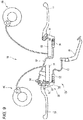
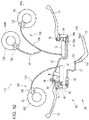
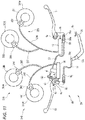
Classifications
-
- B—PERFORMING OPERATIONS; TRANSPORTING
- B62—LAND VEHICLES FOR TRAVELLING OTHERWISE THAN ON RAILS
- B62L—BRAKES SPECIALLY ADAPTED FOR CYCLES
- B62L3/00—Brake-actuating mechanisms; Arrangements thereof
- B62L3/08—Mechanisms specially adapted for braking more than one wheel
-
- B—PERFORMING OPERATIONS; TRANSPORTING
- B60—VEHICLES IN GENERAL
- B60T—VEHICLE BRAKE CONTROL SYSTEMS OR PARTS THEREOF; BRAKE CONTROL SYSTEMS OR PARTS THEREOF, IN GENERAL; ARRANGEMENT OF BRAKING ELEMENTS ON VEHICLES IN GENERAL; PORTABLE DEVICES FOR PREVENTING UNWANTED MOVEMENT OF VEHICLES; VEHICLE MODIFICATIONS TO FACILITATE COOLING OF BRAKES
- B60T8/00—Arrangements for adjusting wheel-braking force to meet varying vehicular or ground-surface conditions, e.g. limiting or varying distribution of braking force
- B60T8/26—Arrangements for adjusting wheel-braking force to meet varying vehicular or ground-surface conditions, e.g. limiting or varying distribution of braking force characterised by producing differential braking between front and rear wheels
- B60T8/261—Arrangements for adjusting wheel-braking force to meet varying vehicular or ground-surface conditions, e.g. limiting or varying distribution of braking force characterised by producing differential braking between front and rear wheels specially adapted for use in motorcycles
-
- B—PERFORMING OPERATIONS; TRANSPORTING
- B62—LAND VEHICLES FOR TRAVELLING OTHERWISE THAN ON RAILS
- B62L—BRAKES SPECIALLY ADAPTED FOR CYCLES
- B62L3/00—Brake-actuating mechanisms; Arrangements thereof
- B62L3/02—Brake-actuating mechanisms; Arrangements thereof for control by a hand lever
- B62L3/023—Brake-actuating mechanisms; Arrangements thereof for control by a hand lever acting on fluid pressure systems
-
- B—PERFORMING OPERATIONS; TRANSPORTING
- B62—LAND VEHICLES FOR TRAVELLING OTHERWISE THAN ON RAILS
- B62L—BRAKES SPECIALLY ADAPTED FOR CYCLES
- B62L3/00—Brake-actuating mechanisms; Arrangements thereof
- B62L3/04—Brake-actuating mechanisms; Arrangements thereof for control by a foot lever
Definitions
- the present invention relates to a vehicle brake system and a vehicle including this vehicle brake system.
- a vehicle brake system for a straddle-type vehicle is known in Patent Literature 1 or the like.
- This vehicle brake system includes a front wheel brake lever provided at one of a right portion and a left portion of a handlebar and an interlocking brake lever provided at the other of the right portion and the left portion of the handlebar.
- a front wheel brake is activated by operating the front wheel brake lever.
- the front wheel brake and a rear wheel brake are activated by operating the interlocking brake lever.
- the vehicle brake system described in Patent Literature 1 is considered to be mounted on a scooter.
- a four-wheeled vehicle is equipped with a brake lever that a driver operate with his or her foot.
- a foot-operating brake operator is mounted on the straddle-type vehicle.
- It is an object of the invention is to provide a vehicle brake system that is easy to be operated by both a person who is accustomed to operating a brake system on a scooter and a person who is accustomed to operating a brake system on a four-wheeled vehicle and a vehicle equipped with this vehicle brake system.
- said object is solved by a vehicle brake system having the features of independent claim 1. Preferred embodiments are laid down in the dependent claims.
- a vehicle brake system including:
- the vehicle brake system may include a second master cylinder configured to activate a second brake device for applying a braking force to the other of the front wheel or the rear wheel of the vehicle, and the second master cylinder may be configured to be operated according to a resultant force of forces applied to the second operator and the third operator.
- At least one of the front wheel or the rear wheel may include a right wheel and a left wheel, and the first brake device may apply a braking force to the right wheel and the left wheel.
- the front wheel may include a right front wheel and a left front wheel
- the first brake device may apply a braking force to the right front wheel and the left front wheel
- the vehicle brake system may include a first mechanical element configured to be moved by at least a force applied to the first operator to operate the first master cylinder, and a second mechanical element configured to be moved by a resultant force of forces applied to the second operator and the third operator to move the first mechanical element.
- the second mechanical element may include:
- the vehicle brake system may include:
- the fourth element may be connected to the first mechanical element with a wire.
- the second element may be connected to the third operator with a wire.
- a first elongated hole may be provided in one of the first mechanical element and the second mechanical element
- a first connector may be provided in the other of the first mechanical element and the second mechanical element, the first connector being configured to move within the first elongated hole, and when the first mechanical element is displaced by an operating force of the first operator, the first mechanical element may be prevented from transmitting the operating force of the first operator to the second mechanical element by the first connector moving within the first elongated hole.
- a second elongated hole may be provided in one of the second element and the third operator
- a second connector may be provided in the other of the second element and the third operator, the second connector being configured to move within the second elongated hole, and when the second element is displaced by an operating force of the second operator, the second element may be prevented from transmitting the operating force of the second operator to the third operator by the second connector moving within the second elongated hole.
- a vehicle including:
- the vehicle brake system that is easy to be operated by both a person who is accustomed to operating a brake system on a scooter and a person who is accustomed to operating a brake system on a four-wheeled vehicle and the vehicle equipped with this vehicle brake system are provided.
- front, rear, left and right mean front, rear, left and right as viewed from a rider who is seated on a seat of a vehicle 1 while gripping on a handlebar 4.
- an arrow F denotes a forward direction of the vehicle 1
- an arrow B denotes a backward direction
- an arrow R denotes a rightward direction
- an arrow L denotes a leftward direction
- an arrow U denotes an upward direction
- an arrow D denotes a downward direction.
- Fig. 1 is a left side view showing a vehicle 1 on which a vehicle brake system 10 according to an embodiment of the invention is mounted.
- This vehicle 1 includes a front wheel 2 and a rear wheel 3 disposed behind the front wheel 2.
- the vehicle 1 includes a handlebar 4, a power unit 5, and the vehicle brake system 10.
- the vehicle 1 includes a head pipe and a vehicle body frame including a main frame connected to the head pipe and the like.
- the head pipe is disposed at a front portion of the vehicle 1. At least part of the vehicle body frame is covered by a vehicle body cover of a resin.
- the power unit 5 is provided between the vehicle body frame and the rear wheel 3.
- the power unit 5 includes an engine 5a, a driving force transmission device 5b, and the like.
- the engine 5a is a unit swing-type engine and is disposed on the vehicle body frame in such a manner as to swing together with the rear wheel 3 in an up-and-down direction.
- the driving force transmission device 5b is disposed behind the engine 5a in a front-and-rear direction of the vehicle 1, and this driving force transmission device 5b transmits a driving force outputted from the engine 5a to the rear wheel 3.
- the engine 5a is disposed forwards of the driving force transmission device 5b in the front-and-rear direction of the vehicle 1, in other words, the driving force transmission device 5b is disposed rearwards of the engine 5a in the front-and-rear direction of the vehicle 1.
- the driving force transmission device 5b includes a continuously variable transmission requiring no clutch operation.
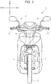
- Fig. 2 is a front view of the vehicle 1.
- a steering shaft 6 is disposed in the head pipe in such a manner as to turn around an axis extending in the up-and-down direction.
- a pair of front suspensions 7, which are disposed parallel to each other, is connected to the steering shaft 6.
- the front wheel 2 is attached rotatably to lower ends of the pair of front suspensions 7.
- the front wheel 2 is turned via the pair of front suspensions 7 by turning the steering shaft 6 around the axis.
- the handlebar 4 which extends in a left-and-right direction, is connected to an upper portion of the steering shaft 6 in such a manner as to be turned relative to the head pipe.
- the vehicle brake system 10 includes a brake operation mechanism 20, a front brake device 30, and a rear brake device 40.
- the front brake device 30 is a device for applying a braking force to the front wheel 2.
- the rear brake device 40 is a device for applying a braking force to the rear wheel 3.
- the brake operation mechanism 20 is a mechanism for receiving an operation by a rider using his or her hand or foot.
- Fig. 3 is a schematic drawing showing the whole of the vehicle brake system 10 when it is not in operation.
- the front brake device 30 of this embodiment is a so-called hydraulic disc brake.
- the front brake device 30 has a front brake disc 31, a front brake caliper 32, and a front brake hose 33.
- the front brake disc 31 is supported by a lower end portion of the front suspension 7 in such a manner as to rotate together with the front wheel 2.
- the front brake caliper 32 is attached to the front suspension 7.
- the front brake caliper 32 includes brake pads configured to hold therebetween the front brake disc 31 in a thickness direction of the front brake disc 31.
- the brake pads are pressed against the front brake disc 31 by means of a hydraulic pressure transmitted by way of the front brake hose 33. As a result, a braking force is applied to the front wheel 2.
- the front brake device 30 includes the one brake disc and the one brake caliper.
- the front brake device 30 may include two or more brake discs and two or more brake calipers that are disposed individually for the corresponding brake discs.
- the rear brake device 40 is also a hydraulic disc brake. That is, the rear brake device 40 also includes a rear brake disc 41, a rear brake caliper 42, and a rear brake hose 43.
- the rear brake device 40 is provided transversely inwards of the driving force transmission device 5b, that is, transversely inwards of a rear portion of the power unit 5.
- the rear brake disc 41 is supported by a swing arm, not shown, in such a manner as to rotate together with the rear wheel 3. Similar to the brake pads of the front brake caliper 32, brake pads of the rear brake caliper 42 are pressed against the rear brake disc 41 by means of a hydraulic pressure transmitted by way of the rear brake hose 43. As a result, a braking force is applied to the rear wheel 3.
- the rear brake device 40 may be configured as a so-called drum brake.
- the brake operation mechanism 20 includes a right lever 11 (a first operator), a left lever 13 (a second operator), and a foot lever 15 (a third operator).
- the front brake device 30 is activated to operate.
- the front brake device 30 and the rear brake device 40 are activated to operate.
- the rider operates only the foot lever 15 the front brake device 30 and the rear brake device 40 are activated to operate.
- the right lever 11 is an operator that can be operated by a right hand of the rider.
- a left portion of the right lever 11 is attached in such a manner as to turn around a right turning shaft portion 4a provided at a right portion of the handlebar 4.
- Aright pushing portion 16 is provided at this right turning shaft portion 4a in such a manner as to turn therearound.
- the left lever 13 is an operator that can be operated by a left hand of the rider. Aright portion of the left lever 13 is attached in such a manner as to turn around a fixed shaft portion 4b provided at a left portion of the handlebar 4.
- the rear master cylinder 14 is pushed.
- a hydraulic pressure generated by the rear master cylinder 14 is transmitted to the rear brake caliper 42, whereby a braking force is applied to the rear wheel 3.
- the front master cylinder 12 is pushed in association with the operation of the left lever 13.
- a hydraulic pressure generated by the front master cylinder 12 is transmitted to the front brake caliper 32, whereby a braking force is applied to the front wheel 2.
- the foot lever 15 is an operator that can be operated by a right foot or a left foot of the rider.
- the foot lever 15 is attached in such a manner as to turn around a turning shaft portion 15a provided on the vehicle body frame.
- One end portion of the foot lever 15 is connected to a foot wire 17.
- the turning shaft portion 15a is provided between a connecting portion 15b with the foot wire 17 and a portion 15c where an operation force is inputted from the foot of the rider.
- the brake operation mechanism 20 includes the right pushing portion 16 (a first mechanical element) and a left pushing mechanism 50 (a second mechanical element).
- the right pushing portion 16 is supported at the right turning shaft portion 4a of the right lever 11 and turns in a clockwise direction in Fig. 3 as the right lever 11 is operated.
- the right pushing portion 16 pushes the front master cylinder 12.
- the clockwise direction and a counterclockwise direction denote turning directions in a state shown in Fig. 3 .
- the state shown in Fig. 3 is a state where the rider mounting on the vehicle 1 views the brake operation mechanism 20.
- Fig. 4 is a drawing showing part of the left pushing mechanism 50 in an enlarged fashion.
- the left pushing mechanism 50 includes a first component 51 (a first element), a second component 52 (a second element), a third component 53 (a third element), a fourth component 54 (a fourth element), a fifth component 55 (a fifth element), a sixth component 56, and an interlocking wire 57.
- first component 51 to sixth component 56 are component independent on one another.
- the first component 51 is provided integrally with a right end portion of the left lever 13.
- the first component 51 is displaced by means of an operation force applied to the left lever 13, independently of an operation force applied to the foot lever 15.
- the first component 51 is supported at a fixed shaft portion 4b provided at a left portion of the handlebar 4 in such a manner as to turn.
- a center axis of the fixed shaft portion 4b will be referred to as a fixed axis A.
- the third component 53 is supported at the fixed shaft portion 4b in such a manner as to turn.
- the third component 53 can be brought into abutment with the first component.
- the third component 53 is biased in the clockwise direction at all times by a biasing means, not shown.
- the third component 53 includes a movable shaft portion 53a and a coupling shaft portion 53b.
- the fixed shaft portion 4b penetrates between the movable shaft portion 53a and the coupling shaft portion 53b.
- the movable shaft portion 53a is a shaft portion that is fixed to the third component 53. Since this shaft portion moves as the third component 53 turns, the shaft portion is called the movable shaft portion 53a.
- the fourth component 54 is supported at the movable shaft portion 53a provided on the third component 53 in such a manner as to turn.
- the fourth component 54 is connected to one end of the interlocking wire 57.
- a center axis of the movable shaft portion 53a will be referred to as a moving axis B.
- the fifth component 55 is supported at the fixed shaft portion 4b in such a manner as to turn.
- the fifth component 55 can be brought into abutment with the fourth component 54.
- the fifth component 55 can push the rear master cylinder 14.
- the first component 51 and the third component 53 are provided in the same position in the direction of the fixed axis A (a vertical direction to a surface of a sheet of paper on which Fig. 4 is drawn). Consequently, when the first component 51 turns around the fixed axis A in the counterclockwise direction, the first component 51 pushes the third component 53, whereby the third component 53 turns around the fixed axis A in the counterclockwise direction.
- the fourth component 54 and the fifth component 55 are provided in the same position in the direction of the fixed axis A.
- the fourth component 54 and the fifth component 55 are provided in a different position from the position where the first component 51 and the third component 53 are provided in the direction of the fixed axis A.
- the fourth component 54 and the fifth component 55 are provided further upwards than the third component 53 above the surface of the sheet of paper in the direction of the fixed axis A.
- the fifth component 55 and an input portion 14a of the rear master cylinder 14 are provided in the same position in the direction of the fixed axis A. Consequently, when the fifth component 55 turns around the fixed axis A in the clockwise direction, the fifth component 55 pushes the rear master cylinder 14.
- the second component 52 is a component having an elongated hole 52a that extends in the left-and-right direction.
- the second component 52 is coupled to the third component 53 in such a manner as to be displaced relatively.
- the coupling shaft portion 53b is inserted through the elongated hole 52a of the second component 52.
- the third component 53 can be displaced relative to the second component 52 by the coupling shaft portion 53b moving inside the elongated hole 52a.
- the second component 52 transmits a force from the foot wire 17 to the third component 53 but does not transmit a force from the third component 53 to the foot wire 17.
- the second component 52 pulls the coupling shaft portion 53b to the right. That is, the second component 52 transmits the force from the foot wire 17 to the third component 53.
- the coupling shaft portion 53b is displaced within the elongated hole 52a in the second component 52, and hence, no force is transmitted from the third component 53 to the second component 52.
- the sixth component 56 is a component having an elongated hole 56a.
- the sixth component 56 is coupled to the right pushing portion 16 in such a manner as to be displaced relatively.
- a coupling shaft portion 16a is inserted through the elongated hole 56a in the sixth component 56.
- the right pushing portion 16 can be displaced relative to the sixth component 56 by the coupling shaft portion 16a moving inside the elongated hole 56a.
- the sixth component 56 transmits a force from the coupling wire 57 to the right pushing portion 16 but does not transmit a force from the right pushing portion 16 to the coupling wire 57.
- the sixth component 56 pulls the coupling shaft portion 16a to the left. That is, the sixth component 56 transmits the force from the interlocking wire 57 to the coupling shaft portion 16a.
- the coupling shaft portion 16a is displaced within the elongated hole 56a in the sixth component 56, and hence, no force is transmitted from the right pushing portion 16 to the sixth component 56.
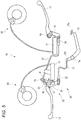
- Fig. 5 is a schematic drawing showing the whole of the vehicle brake system 10 when the rider activates the left lever 13. As shown in Fig. 5 , when the rider operates only the left lever 13, the right lever 11 does not operate, and the foot lever 15 does not operate, either. In this state, the front brake device 30 and the rear brake device 40 operate.
- Fig. 4 shows a state of the left lever 13 resulting immediately before the left lever 13 is operated. Movement acting to the relevant components are indicated by arrows a to e in Fig. 4 .
- the fourth component 54 pulls the interlocking wire 57 and turns the fifth component 55 will be described in detail.
- the fourth component 54 pulls the interlocking wire 57 to the left
- the fourth component 54 receives a reaction force from the interlocking wire 57 and attempts to turn around the moving axis B in the clockwise direction.
- the fifth component 55 receives a reaction force from the rear master cylinder 14 when it pushes the rear master cylinder 14. This reaction force attempts to turn the fifth component 55 around the fixed axis A in the clockwise direction.
- This reaction force makes the fifth component 55 attempt to turn the fourth component 54 around the moving axis B in the counterclockwise direction.
- the fourth component 54 when the fourth component 54 pulls the interlocking wire 57 to the left, the fourth component 54 receives the two types of reaction forces that act in directions in which the two forces offset each other from the interlocking wire 57 and the fifth component 55.
- the fourth component 54 turns around the moving axis B to a position where those reaction forces are in balance. That is, the fourth component 54 moves in such a manner as to revolve around the fixed axis A while turning on its own axis around the moving axis B.
- the fourth component 54 displaces the interlocking wire 57 to the left and turns the fifth component 55 around the fixed axis A in the counterclockwise direction.
- the third component 53 that is moved by the first component 51 includes the coupling shaft portion 53b.
- This coupling shaft portion 53b is inserted through the elongated hole 52a provided in the second component 52 in such a manner as to move therein freely.
- the coupling shaft portion 53b moves to the right.
- the coupling shaft portion 53b moves within the elongated hole 52a in the second component 52 and does not displace the second component 52. Consequently, even when the first component 51 turns, no force is transmitted to the foot lever 15 by way of the second component 52 and the foot wire 17, whereby the foot lever 15 is not activated to operate.
- the interlocking wire 57 displaces the sixth component 56 to the left.
- the elongated hole 56a extending in the left-and-right direction is provided in the sixth component 56.
- the sixth component 56 displaces the coupling shaft portion 16a, which is inserted through the elongated hole 56a, to the left.
- the right pushing portion 16 turns around the right turning shaft portion 4a in the clockwise direction, activating the front master cylinder 12.
- a hydraulic pressure generated by the front master cylinder 12 is transmitted to the front brake caliper 32, whereby a braking force is applied to the front wheel 2.
- the right pushing portion 16 transmits no force to the right lever 11.
- the right pushing portion 16 is a component independent of the right lever 11. As a result, even though the right pushing portion 16 turns in the clockwise direction with no force inputted into the right lever 11, the right pushing portion 16 is spaced away from the right lever 11, and no force is transmitted to the right lever 11. In other words, even when the left lever 13 is operated, the right lever 11 is not operated.
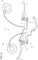
- Fig. 6 is a schematic drawing showing the whole of the vehicle brake system 10 when the rider activates the foot lever 15. As shown in Fig. 6 , when the rider operates only the foot lever 15, the left lever 13 does not operate, and the right lever 11 does not operate, either. In this state, the front brake device 30 and the rear brake device 40 operate.
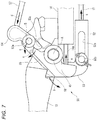
- Fig. 7 is a drawing showing part of the left pushing mechanism 50 when the rider operates the foot lever 15.
- Fig. 7 illustrates a state of the foot lever 15 resulting immediately before the foot lever 15 is operated. Movement acting to the relevant components are indicated by arrows a to e in Fig. 7 .
- the third component 53 transmits no force to the first component 51.
- the third component 53 is a component independent of the first component 51.
- the third component 53 is spaced away from the first component 51, whereby the third component 53 transmits no force to the left lever 13 that is integrated with the first component 51. In other words, even though the foot lever 15 is operated, the left lever 13 is not operated.
- the right pushing portion 16 transmits no force to the right lever 11.
- the right pushing portion 16 is a component independent of the right lever 11. As a result, even though the right pushing portion 16 turns in the clockwise direction with no force inputted into the right lever 11, the right pushing portion 16 is spaced away from the right lever 11, and no force is transmitted to the right lever 11. In other words, even though the foot lever 15 operates, the right lever 11 does not operate.
- Fig. 8 is a schematic drawing showing the whole of the vehicle brake system 10 when the rider activates the right lever 11. As shown in Fig. 8 , when the rider operates only the right lever 11, the left lever 13 does not operate, and the foot lever 15 does not operate, either. In this state, the front brake device 30 and the rear brake device 40 operate.
- the sixth component 56 is a component independent of the right pushing portion 16.
- the sixth component 56 has an elongated hole 56a extending in the left-and-right direction, and the coupling shaft portion 16a is inserted through this elongated hole 56a in such a manner as to move freely therein. A force attempting to pull the sixth component 56 to the left is applied to the sixth component 56 at all times. As a result, when the sixth component 56 moves to the left by activating the left lever 13 and the foot lever 15, the sixth component 56 turns the right pushing portion 16 in the clockwise direction via the coupling shaft portion 16a.
- the vehicle brake system 10 includes:
- the front master cylinder 12 can be activated to operate by operating the left lever 13.
- the front master cylinder 12 can be activated to operate by operating the foot lever 15.
- the front master cylinder 12 can be activated to operate by operating the right lever 11.
- the front master cylinder 12 is configured to be operated by means of the resultant force of the forces applied to the right lever 11, the left lever 13, and the foot lever 15. That is, the front master cylinder 12 is activated to operate by means of a resultant force of the forces applied to the right lever 11 and the left lever 13. The front master cylinder 12 is activated to operate by means of a resultant force of the forces applied to the left lever 13 and the foot lever 15. The front master cylinder 12 is activated to operate by means of a resultant force of the forces applied to the right lever 11 and the foot lever 15. The front master cylinder 12 is activated to operate by means of the resultant force of the forces applied to the right lever 11, the left lever 13, and the foot lever 15.
- the front master cylinder 12 is activated to operate by means of the resultant force of the forces applied to the right lever 11, the left lever 13, and the foot lever 15 will be described.
- the front master cylinder 12 is activated to operate by turning of the right pushing portion 16.
- the right pushing portion 16 is moved by at least an operation force applied to the right lever 11.
- the right pushing portion 16 is described as being moved by means of an operation force applied to the left lever 13, or an operation force applied to the foot lever 15.
- the fact that the right pushing portion 16 is also moved by means of a resultant force of a force applied to the right lever 11, a force applied to the left lever 13, and a force applied to the foot lever 15.
- Fig. 9 is a schematic drawing showing the whole of the vehicle brake system 10 when the right lever 11, the left lever 13, and the foot lever 15 are all operated. For example, when the rider attempts to generate a maximum braking force in the front wheel 2 and the rear wheel 3, the rider operates all of the right lever 11, the left lever 13, and the foot lever 15.
- the third component 53 applies to the fourth component 54 force attempting to revolve the fourth component 54 around the fixed axis A in the counterclockwise direction.
- This force applied to the fourth component 54 acts in such a way as to pull the coupling shaft portion 16a to the left via the interlocking wire 57 and the sixth component 56.
- the operation force inputted into the right lever 11 is transmitted to the right pushing portion 16.
- the force attributed to the operation of the foot lever 15, the force attributed to the third component 53 to which the resultant force of the force attributed to the operation of the foot lever 15 and the force attributed to the operation of the left lever 13, and the force attributed to the operation of the right lever 11 are applied to the right pushing portion 16 configured to activate the front master cylinder 12.
- the front master cylinder 12 is configured to be operated by means of the resultant force of the right lever 11, the left lever 13, and the foot lever 15.
- the case where only the right lever 11 is activated to operate which is described above, constitutes a case where an operation force of a certain magnitude (X[N]) is inputted into the right lever 11, an operation force of 0 (zero) [N] is inputted into the left lever 13, and an operation force of 0 (zero) [N] is inputted into the foot lever 15.
- the force inputted into the front master cylinder 12 is not always the total of the forces that are inputted individually into the right lever 11, the left lever 13, and the foot lever 15.
- the force inputted into the front master cylinder 12 is proportional to a total of magnitudes of forces that are inputted individually into the right lever 11, the left lever 13, and the foot lever 15.
- the vehicle brake system 10 is configured so that there is a case where the vehicle brake system 10 is operated according to the resultant force of the forces applied to the foot lever 15, the left lever 13, and the right lever 11 sometimes.
- the front master cylinder 12 is preferably configured to be operated by means of the resultant force of the forces applied to the foot lever 15, the left lever 13, and the right lever 11 at all times. Then, for example, it is preferable to configure so that the force with which the foot lever 15 turns the third component 53 becomes greater than the force with which the left lever 13 turns the third component 53 when the foot lever 15 moves to its extreme position in a stroke. Additionally, it is preferable to configure so that the forces with which the foot lever 15 and the left lever 13 pull the sixth component 56 to the left become greater than the force with which the right lever 11 turns the right pushing portion 16 when the foot lever 15 moves to its extreme position in a stroke and the left lever 13 moves to its extreme position in a stroke.
- the front master cylinder 12 can be activated to operate by operating any one of the three operators of the right lever 11, the left lever 13, and the foot lever 15, whereby the handling properties of the vehicle brake system 10 by the use can be enhanced.
- the user when the user is accustomed to operating the brake system on a scooter, the user can activate the front brake device 30 and the rear brake device 40 to operate by using the right lever 11 and the left lever 13.
- the user when the user is accustomed to operating the brake system on a four-wheeled vehicle, the user can activate the front brake device 30 and the rear brake device 40 to operate by using the foot lever 15 and the right lever 11 or even by using only the foot lever 15.
- the vehicle brake system 10 of this embodiment is easy to be used by not only a user who is accustomed to operating the brake system on a scooter but also a user who is accustomed to operating the brake system on a four-wheeled vehicle.
- the front master cylinder 12 Since the front master cylinder 12 is operated according to the resultant force of the forces applied to the right lever 11, the left lever 13, and the foot lever 15, an excessive force does not have to be applied to the single operator in order to output a great force from the front master cylinder 12.
- a great force from the front master cylinder when a great force from the front master cylinder is needed, for example, it may be required to input a great force into the right lever when the front master cylinder is operated by only the right lever.
- the front master cylinder 12 can be allowed to output a similar great force.
- the vehicle brake system 10 includes the right pushing portion 16 (a first mechanical element) configured to be moved by means of the force by at least the right lever 11 to operate the front master cylinder 12 and the left pushing mechanism 50 configured to be moved by means of the resultant force of the forces applied to the left lever 13 and the foot lever 15 to move the right pushing portion 16.
- the right pushing portion 16 a first mechanical element
- the left pushing mechanism 50 configured to be moved by means of the resultant force of the forces applied to the left lever 13 and the foot lever 15 to move the right pushing portion 16.
- the first master cylinder is configured to be operated according to the resultant force of the forces applied to the first operator, the second operator, and the third operator through the mechanical mechanism.
- the necessity of a complex control is obviated.
- the vehicle brake system 10 includes the rear master cylinder 14 configured to operate the rear brake device for applying a braking force to the rear wheel 3, and the rear master cylinder 14 is configured to be operated according to the resultant force of the forces applied to the left lever 13 (the second operator) and the foot lever 15 (the third operator).
- the left pushing mechanism 50 is configured to be moved by means of the resultant force of the forces applied to the left lever 13 and the foot lever 15 to operate the rear master cylinder 14.
- the left pushing mechanism 50 includes:
- the front master cylinder 12 can be activated to operate by operating any one of the three operators of the right lever 11, the left lever 13 and the foot lever 15 with the simple configuration. Additionally, the front master cylinder 12 can be operated according to the resultant force of the forces applied to the right lever 11, the left lever 13, and the foot lever 15.
- the vehicle brake system 10 includes the fifth component 55 configured to be moved by the fourth component 54 to operate the rear master cylinder 14.
- the front master cylinder 12 and the rear master cylinder 14 can both be activated to operate by operating the left lever 13 or the foot lever 15.
- the fourth component 54 is connected to the right pushing portion 16 with the wire (the interlocking wire 57).
- the movement of the fourth component 54 can be transmitted to the right pushing portion 16 in an ensured fashion through the simple configuration of the interlocking wire 57.
- the second component 52 is connected to the foot lever 15 with the wire (the foot wire 17).
- the movement of the foot lever 15 can be transmitted to the second component 52 in an ensured fashion through the simple configuration of the foot wire 17.
- the foot lever 15 is provided far away of the position where the second component 52 is provided, and other members are provided between the foot lever 15 and the second component 52.
- the movement of the foot lever 15 can be transmitted to the second component 52 in an ensured fashion while avoiding an interference with other members by connecting the foot lever 15 and the second component 52 with the wire.
- the right pushing portion 16 is configured in such a manner as not to transmit an operation force of the right lever 11 to the left pushing mechanism 50.
- the first elongated hole 56a is provided in one (the sixth component 56 of the left pushing mechanism 50) of the first mechanical element (the right pushing portion 16) and the second mechanical element (the left pushing mechanism 50), a first connector (the coupling shaft portion 16a) configured to move within the first elongated hole 56a is provided on the other (the coupling shaft portion 16a) of the first mechanical element (the right pushing portion 16) and the second mechanical element (the left pushing mechanism 50), and when the first mechanical element (the right pushing portion 16) is displaced by means of the operation force of the first operator (the right lever 11), the fist connector (the coupling shaft portion 16a) moves within the first elongated hole 56a, so that the first mechanical element (the right pushing portion 16) is prevented from transmitting the operation force of the first operator (the right lever 11) to the second mechanical element (the left pushing mechanism 50).
- the sixth component 56 is a component independent of the right pushing portion 16.
- the sixth component 56 has an elongated hole 56a extending in the left-and-right direction, and the coupling shaft portion 16a is inserted through this elongated hole 56a in such a manner as to move freely therein. A force attempting to pull the sixth component 56 to the left is applied to the sixth component 56 at all times. As a result, when the sixth component 56 moves to the left, the sixth component 56 turns the right pushing portion 16 in the clockwise direction via the coupling shaft portion 16a.
- the second component 52 is configured in such a manner as not to transmit the operation force of the left lever 13 to the foot lever 15.
- the second elongated hole 52a is provided in one (the second component 52) of the second element (the second component 52) and the third operator (the third component 53), a second connector (the coupling shaft portion 53b) configured to move within the second elongated hole 52a is provided on the other (the third component 53) of the second element (the second component 52) and the third operator (the third component), and when the second element (the second component 52) is displaced by means of the operation force of the second operator (the left lever 13), the second connector (the coupling shaft portion 53b) moves within the second elongated hole 52a, so that the second element (the second component 52) is prevented from transmitting the operation force of the second operator (the left lever 13) to the third operator (the fool lever 15).
- the second component 52 is a component independent of the left lever 13.
- the second component 52 has the elongated hole 52a extending in the left-and-right direction, and the coupling shaft portion 53b configured to be activated to operate by the left lever 13 is inserted through the elongated hole 52a in such a manner as to move therein.
- the force attempting to turn third component 53 in the counterclockwise direction is applied to the third component 53 at all times, and the coupling shaft portion 53b is biased to the right at all times.
- the second component 52 moves the coupling shaft portion 53b to the right and turns the third component 53 in the counterclockwise direction.
- the coupling shaft portion 53b only moves to the right within the elongated hole 52a in the second component 52, and there occurs no such situation that the third component 53 moves the second component 52 to the right.
- the second component 52 is configured in such a manner as not to transmit the operation force of the left lever 13 to the foot lever 15.
- the rear brake device 40 can be activated to operate.
- a stopper 53c is provided on the third component 53.
- the stopper 53c is a portion projecting from the third component 53 upwards above the surface of a sheet of paper on which Fig. 5 is drawn so as to be brought into abutment with the fourth component 54.
- the stopper 53c is brought into abutment with the fourth component 54 to thereby prevent the fourth component 54 from turning around the moving axis B in the counterclockwise direction.
- the front brake device 30 can be activated to operate.
- the operation of the right lever 11 is transmitted to the front master cylinder 12 irrespective of the state of the rear brake hose 43.
- the front brake device 30 can be activated to operate.
- the second operator is described as being the left lever 13 that can be operated by the left hand of the rider
- the second operator may be configured as a second foot lever that can be operated by a different foot of the rider from the foot by which the foot lever 15, which is the third operator, is operated.
- vehicle brake system 10 is described as being mounted on the motorcycle including the one front wheel and the one rear wheel, the invention is not limited to this.
- the vehicle brake system 110 may be mounted on a vehicle 101 with two front wheels that includes a right front wheel 102A and a left front wheel 102B, and one rear wheel 103.
- a first brake device 130 that is activated by a first master cylinder 12 is preferably configured to apply a braking force to the right front wheel 102A and the left front wheel 102B.
- the first brake device 130 may include a right front brake caliper 132 configured to apply a frictional force to a right front brake disc 131 that rotates together with the right front wheel 102A, a left front brake caliper 136 configured to apply a frictional force to a left front brake disc 135 that rotates together with the left front wheel 102B, a right front brake hose 134 that connects the front master cylinder 12 with the right front brake caliper 132, and a left front brake hose 137 that connects the front master cylinder 12 with the left front brake caliper 136.
- part of the right front brake hose 134 and part of the left front brake hose 137 are made up of a common hose. Being different from this configuration, the right front brake hose 134 and the left front brake hose 137 may each be made up of an independent hose.
- the vehicle brake system may be mounted on a vehicle with two rear wheels that includes one front wheel, and a right rear wheel and a left rear wheel.
- a vehicle brake system 210 may be mounted on a four-wheeled vehicle including a right front wheel 202A, a left front wheel 202B, a right rear wheel 203A, and a left rear wheel 203B.
- a first brake device 230 may include a right front brake caliper 232 configured to apply a frictional force to a right front brake disc 231 that rotates together with the right front wheel 202A, a left front brake caliper 236 configured to apply a frictional force to a left front brake disc 235 that rotates together with the left front wheel 202B, a right front brake hose 234 that connects a front master cylinder 12 with the right front brake caliper 232, and a left front brake hose 237 that connects the front master cylinder 12 with the left front brake caliper 236.
- a second brake device 240 may include a right rear brake caliper 242 configured to apply a frictional force to a right rear brake disc 241 that rotates together with the right rear wheel 203A, a left rear brake caliper 246 configured to apply a frictional force to a left rear brake disc 245 that rotates together with the left rear wheel 203B, a right rear brake hose 244 that connects a rear master cylinder 14 with the right rear brake caliper 242, and a left rear brake hose 247 that connects the rear master cylinder 14 with the left rear brake caliper 246.
- the front master cylinder 12 is described as being activated to operate by the right lever 11, and the front master cylinder 12 and the rear master cylinder 14 are described as being activated to operate by the left lever 13 and the foot lever 15; however, the invention is not limited to this configuration.
- the front master cylinder may be activated to operate by the left lever, and the front master cylinder and the rear master cylinder may be activated to operate by the right lever and the foot lever.
- the front master cylinder 12 When the left lever 13 and the foot lever 15 are operated, the front master cylinder 12 may be activated to operate after the rear master cylinder 14 is activated to operate, or the rear master cylinder 14 may be activated to operate after the front master cylinder 12 is activated to operate. Alternatively, the front master cylinder 12 and the rear master cylinder 14 may be activated to operate simultaneously when the left lever 13 or the foot lever 15 is operated.
Landscapes
- Engineering & Computer Science (AREA)
- Mechanical Engineering (AREA)
- Transportation (AREA)
- Physics & Mathematics (AREA)
- Fluid Mechanics (AREA)
- Transmission Of Braking Force In Braking Systems (AREA)
- Braking Elements And Transmission Devices (AREA)
Abstract
Description
- The present invention relates to a vehicle brake system and a vehicle including this vehicle brake system.
- A vehicle brake system for a straddle-type vehicle is known in Patent Literature 1 or the like. This vehicle brake system includes a front wheel brake lever provided at one of a right portion and a left portion of a handlebar and an interlocking brake lever provided at the other of the right portion and the left portion of the handlebar. A front wheel brake is activated by operating the front wheel brake lever. The front wheel brake and a rear wheel brake are activated by operating the interlocking brake lever.
- [Patent Literature 1]
JP 2008-290699 A - Incidentally, the vehicle brake system described in Patent Literature 1 is considered to be mounted on a scooter. On the other hand, a four-wheeled vehicle is equipped with a brake lever that a driver operate with his or her foot. Thus, in the case where a person who is accustomed to operating a brake system on a four-wheeled vehicle tries to ride a straddle-type vehicle, it is considered to be preferable that a foot-operating brake operator is mounted on the straddle-type vehicle.
- It is an object of the invention is to provide a vehicle brake system that is easy to be operated by both a person who is accustomed to operating a brake system on a scooter and a person who is accustomed to operating a brake system on a four-wheeled vehicle and a vehicle equipped with this vehicle brake system. According to the present invention said object is solved by a vehicle brake system having the features of independent claim 1. Preferred embodiments are laid down in the dependent claims.
- According to an aspect of the invention, there is provided a vehicle brake system including:
- a first master cylinder configured to activate a first brake device for applying a braking force to at least one of a front wheel or a rear wheel of a vehicle;
- a first operator configured to be operated by a hand of a user;
- a second operator configured to be operated by a hand or a foot of the user; and
- a third operator configured to be operated by a foot of the user,
- wherein the first master cylinder is configured to be operated according to a resultant force of forces applied to the first operator, the second operator, and the third operator.
- In the vehicle brake system described above, the vehicle brake system may include a second master cylinder configured to activate a second brake device for applying a braking force to the other of the front wheel or the rear wheel of the vehicle, and the second master cylinder may be configured to be operated according to a resultant force of forces applied to the second operator and the third operator.
- In the vehicle brake system described above, at least one of the front wheel or the rear wheel may include a right wheel and a left wheel, and the first brake device may apply a braking force to the right wheel and the left wheel.
- In the vehicle brake system described above, the front wheel may include a right front wheel and a left front wheel, and the first brake device may apply a braking force to the right front wheel and the left front wheel.
- In the vehicle brake system described above, the vehicle brake system may include a first mechanical element configured to be moved by at least a force applied to the first operator to operate the first master cylinder, and a second mechanical element configured to be moved by a resultant force of forces applied to the second operator and the third operator to move the first mechanical element.
- In the vehicle brake system described above, the second mechanical element may include:
- a first element configured to move according to a force applied to the second operator independently of a force by the third operator;
- a second element configured to move according to a force applied to the third operator independently of a force by the second operator;
- a third element configured to be moved by the first element or the second element; and
- a fourth element configured to be moved by the third operator to operate the first master cylinder.
- In the vehicle brake system described above, the vehicle brake system may include:
- a second master cylinder configured to activate a second brake device for applying a braking force to the other of the front wheel or the rear wheel; and
- a fifth element configured to be moved by the fourth element to operate the second master cylinder.
- In the vehicle brake system described above, the fourth element may be connected to the first mechanical element with a wire.
- In the vehicle brake system described above, the second element may be connected to the third operator with a wire.
- In the vehicle brake system described above, a first elongated hole may be provided in one of the first mechanical element and the second mechanical element, a first connector may be provided in the other of the first mechanical element and the second mechanical element, the first connector being configured to move within the first elongated hole, and when the first mechanical element is displaced by an operating force of the first operator, the first mechanical element may be prevented from transmitting the operating force of the first operator to the second mechanical element by the first connector moving within the first elongated hole.
- In the vehicle brake system described above, a second elongated hole may be provided in one of the second element and the third operator, a second connector may be provided in the other of the second element and the third operator, the second connector being configured to move within the second elongated hole, and when the second element is displaced by an operating force of the second operator, the second element may be prevented from transmitting the operating force of the second operator to the third operator by the second connector moving within the second elongated hole.
- According to another aspect of the invention, there is provided a vehicle including:
- a front wheel;
- a rear wheel; and
- a vehicle brake system including a second master cylinder configured to activate a first brake device for applying a braking force to one the front wheel or the rear wheel.
- According to the invention, the vehicle brake system that is easy to be operated by both a person who is accustomed to operating a brake system on a scooter and a person who is accustomed to operating a brake system on a four-wheeled vehicle and the vehicle equipped with this vehicle brake system are provided.
-
-
Fig. 1 is a left side view showing a vehicle on which a vehicle brake system according to an embodiment of the invention is mounted. -
Fig. 2 is a front view of the vehicle shown inFig. 1 . -
Fig. 3 is a schematic drawing showing the whole of the vehicle brake system when the vehicle brake system is not in operation. -
Fig. 4 is a schematic drawing showing the whole of the vehicle brake system when a left lever is activated to operate. -
Fig. 5 is a drawing showing part of a left pushing mechanism when the left lever is operated. -
Fig. 6 is a schematic drawing showing the whole of the vehicle brake system when a foot lever is in operation. -
Fig. 7 is a drawing showing part of the left pushing mechanism when the foot lever is operated. -
Fig. 8 is a schematic drawing showing the whole of the vehicle brake system when a right lever is in operation. -
Fig. 9 is a schematic drawing showing the whole of the vehicle brake system when the right lever, the left lever, and the foot lever are all in operation. -
Fig. 10 is a schematic drawing showing the whole of a vehicle brake system according to a first modified example of the invention. -
Fig. 11 is a schematic drawing showing the whole of a vehicle brake system according to a second modified example of the invention. - Hereinafter, referring to drawings, an embodiment of the invention will be described. Dimensions of constituent elements shown in the individual drawings do not represent truly actual dimensions of the constituent elements and dimensional ratios of the constituent elements.
- In the following description, front, rear, left and right mean front, rear, left and right as viewed from a rider who is seated on a seat of a vehicle 1 while gripping on a
handlebar 4. In the drawings, an arrow F denotes a forward direction of the vehicle 1, an arrow B denotes a backward direction, an arrow R denotes a rightward direction, an arrow L denotes a leftward direction, an arrow U denotes an upward direction, and an arrow D denotes a downward direction. -
Fig. 1 is a left side view showing a vehicle 1 on which avehicle brake system 10 according to an embodiment of the invention is mounted. This vehicle 1 includes afront wheel 2 and arear wheel 3 disposed behind thefront wheel 2. - The vehicle 1 includes a
handlebar 4, apower unit 5, and thevehicle brake system 10. The vehicle 1 includes a head pipe and a vehicle body frame including a main frame connected to the head pipe and the like. The head pipe is disposed at a front portion of the vehicle 1. At least part of the vehicle body frame is covered by a vehicle body cover of a resin. - As shown in
Fig.1 , thepower unit 5 is provided between the vehicle body frame and therear wheel 3. Thepower unit 5 includes anengine 5a, a drivingforce transmission device 5b, and the like. - The
engine 5a is a unit swing-type engine and is disposed on the vehicle body frame in such a manner as to swing together with therear wheel 3 in an up-and-down direction. The drivingforce transmission device 5b is disposed behind theengine 5a in a front-and-rear direction of the vehicle 1, and this drivingforce transmission device 5b transmits a driving force outputted from theengine 5a to therear wheel 3. Theengine 5a is disposed forwards of the drivingforce transmission device 5b in the front-and-rear direction of the vehicle 1, in other words, the drivingforce transmission device 5b is disposed rearwards of theengine 5a in the front-and-rear direction of the vehicle 1. In this embodiment, the drivingforce transmission device 5b includes a continuously variable transmission requiring no clutch operation. -
Fig. 2 is a front view of the vehicle 1. A steeringshaft 6 is disposed in the head pipe in such a manner as to turn around an axis extending in the up-and-down direction. A pair offront suspensions 7, which are disposed parallel to each other, is connected to thesteering shaft 6. Thefront wheel 2 is attached rotatably to lower ends of the pair offront suspensions 7. Thefront wheel 2 is turned via the pair offront suspensions 7 by turning thesteering shaft 6 around the axis. - The
handlebar 4, which extends in a left-and-right direction, is connected to an upper portion of thesteering shaft 6 in such a manner as to be turned relative to the head pipe. Aright lever 11 and afront master cylinder 12, both of which will be described later, are attached to a right portion of thehandlebar 4. Aleft lever 13 and arear master cylinder 14, both of which will be described later, are attached to a left portion of thehandlebar 4. - Next, the
vehicle brake system 10 provided on the vehicle 1 will be described in detail. As shown inFig. 1 , thevehicle brake system 10 includes abrake operation mechanism 20, afront brake device 30, and arear brake device 40. Thefront brake device 30 is a device for applying a braking force to thefront wheel 2. Therear brake device 40 is a device for applying a braking force to therear wheel 3. Thebrake operation mechanism 20 is a mechanism for receiving an operation by a rider using his or her hand or foot. -
Fig. 3 is a schematic drawing showing the whole of thevehicle brake system 10 when it is not in operation. As shown inFig. 3 , thefront brake device 30 of this embodiment is a so-called hydraulic disc brake. Thefront brake device 30 has afront brake disc 31, afront brake caliper 32, and afront brake hose 33. - As shown in
Fig. 1 , thefront brake disc 31 is supported by a lower end portion of thefront suspension 7 in such a manner as to rotate together with thefront wheel 2. Thefront brake caliper 32 is attached to thefront suspension 7. Thefront brake caliper 32 includes brake pads configured to hold therebetween thefront brake disc 31 in a thickness direction of thefront brake disc 31. The brake pads are pressed against thefront brake disc 31 by means of a hydraulic pressure transmitted by way of thefront brake hose 33. As a result, a braking force is applied to thefront wheel 2. - In this embodiment, the
front brake device 30 includes the one brake disc and the one brake caliper. However, thefront brake device 30 may include two or more brake discs and two or more brake calipers that are disposed individually for the corresponding brake discs. - As shown in
Fig. 3 , in this embodiment, similar to thefront brake device 30 described above, therear brake device 40 is also a hydraulic disc brake. That is, therear brake device 40 also includes arear brake disc 41, arear brake caliper 42, and arear brake hose 43. Therear brake device 40 is provided transversely inwards of the drivingforce transmission device 5b, that is, transversely inwards of a rear portion of thepower unit 5. - The
rear brake disc 41 is supported by a swing arm, not shown, in such a manner as to rotate together with therear wheel 3. Similar to the brake pads of thefront brake caliper 32, brake pads of therear brake caliper 42 are pressed against therear brake disc 41 by means of a hydraulic pressure transmitted by way of therear brake hose 43. As a result, a braking force is applied to therear wheel 3. Therear brake device 40 may be configured as a so-called drum brake. - As shown in
Fig. 3 , thebrake operation mechanism 20 includes a right lever 11 (a first operator), a left lever 13 (a second operator), and a foot lever 15 (a third operator). In this embodiment, when the rider operates only theright lever 11, thefront brake device 30 is activated to operate. When the rider operates only theleft lever 13, thefront brake device 30 and therear brake device 40 are activated to operate. When the rider operates only thefoot lever 15, thefront brake device 30 and therear brake device 40 are activated to operate. - The
right lever 11 is an operator that can be operated by a right hand of the rider. A left portion of theright lever 11 is attached in such a manner as to turn around a rightturning shaft portion 4a provided at a right portion of thehandlebar 4. Aright pushingportion 16 is provided at this right turningshaft portion 4a in such a manner as to turn therearound. When the rider pulls theright lever 11 with his or her right hand, thefront master cylinder 12 is pushed. As a result, a hydraulic pressure generated by thefront master cylinder 12 is transmitted to thefront brake caliper 32, whereby a braking force is applied to thefront wheel 2. - The
left lever 13 is an operator that can be operated by a left hand of the rider. Aright portion of theleft lever 13 is attached in such a manner as to turn around a fixedshaft portion 4b provided at a left portion of thehandlebar 4. When the rider pulls theleft lever 13 with his or her left hand, therear master cylinder 14 is pushed. As a result, a hydraulic pressure generated by therear master cylinder 14 is transmitted to therear brake caliper 42, whereby a braking force is applied to therear wheel 3. Additionally, thefront master cylinder 12 is pushed in association with the operation of theleft lever 13. As a result, a hydraulic pressure generated by thefront master cylinder 12 is transmitted to thefront brake caliper 32, whereby a braking force is applied to thefront wheel 2. - The
foot lever 15 is an operator that can be operated by a right foot or a left foot of the rider. Thefoot lever 15 is attached in such a manner as to turn around a turningshaft portion 15a provided on the vehicle body frame. One end portion of thefoot lever 15 is connected to afoot wire 17. The turningshaft portion 15a is provided between a connectingportion 15b with thefoot wire 17 and aportion 15c where an operation force is inputted from the foot of the rider. - When the rider depresses the
foot lever 15 with his or her foot, thefoot wire 17 is pulled, and therear master cylinder 14 is pushed. As a result, a hydraulic pressure generated by therear master cylinder 14 is transmitted to therear brake caliper 42, whereby a braking force is applied to therear wheel 3. In addition, thefront master cylinder 12 is pushed in association with the operation of thefoot lever 15. As a result, a hydraulic pressure generated by thefront master cylinder 12 is transmitted to thefront brake caliper 32, whereby a braking force is applied to thefront wheel 2. - Next, the
brake operation mechanism 20 will be described in detail. As shown inFig. 3 , thebrake operation mechanism 20 includes the right pushing portion 16 (a first mechanical element) and a left pushing mechanism 50 (a second mechanical element). Theright pushing portion 16 is supported at the rightturning shaft portion 4a of theright lever 11 and turns in a clockwise direction inFig. 3 as theright lever 11 is operated. When theright pushing portion 16 turns in the clockwise direction, theright pushing portion 16 pushes thefront master cylinder 12. - In the following description, the clockwise direction and a counterclockwise direction denote turning directions in a state shown in
Fig. 3 . The state shown inFig. 3 is a state where the rider mounting on the vehicle 1 views thebrake operation mechanism 20. -
Fig. 4 is a drawing showing part of the left pushingmechanism 50 in an enlarged fashion. As shown inFig. 4 , the left pushingmechanism 50 includes a first component 51 (a first element), a second component 52 (a second element), a third component 53 (a third element), a fourth component 54 (a fourth element), a fifth component 55 (a fifth element), asixth component 56, and an interlockingwire 57. Thesefirst component 51 tosixth component 56 are component independent on one another. - The
first component 51 is provided integrally with a right end portion of theleft lever 13. Thefirst component 51 is displaced by means of an operation force applied to theleft lever 13, independently of an operation force applied to thefoot lever 15. Thefirst component 51 is supported at a fixedshaft portion 4b provided at a left portion of thehandlebar 4 in such a manner as to turn. In the following description, a center axis of the fixedshaft portion 4b will be referred to as a fixed axis A. - The
third component 53 is supported at the fixedshaft portion 4b in such a manner as to turn. Thethird component 53 can be brought into abutment with the first component. Thethird component 53 is biased in the clockwise direction at all times by a biasing means, not shown. Thethird component 53 includes amovable shaft portion 53a and acoupling shaft portion 53b. The fixedshaft portion 4b penetrates between themovable shaft portion 53a and thecoupling shaft portion 53b. Themovable shaft portion 53a is a shaft portion that is fixed to thethird component 53. Since this shaft portion moves as thethird component 53 turns, the shaft portion is called themovable shaft portion 53a. - The
fourth component 54 is supported at themovable shaft portion 53a provided on thethird component 53 in such a manner as to turn. Thefourth component 54 is connected to one end of the interlockingwire 57. In the following description, a center axis of themovable shaft portion 53a will be referred to as a moving axis B. - The
fifth component 55 is supported at the fixedshaft portion 4b in such a manner as to turn. Thefifth component 55 can be brought into abutment with thefourth component 54. Thefifth component 55 can push therear master cylinder 14. - The
first component 51 and thethird component 53 are provided in the same position in the direction of the fixed axis A (a vertical direction to a surface of a sheet of paper on whichFig. 4 is drawn). Consequently, when thefirst component 51 turns around the fixed axis A in the counterclockwise direction, thefirst component 51 pushes thethird component 53, whereby thethird component 53 turns around the fixed axis A in the counterclockwise direction. - The
fourth component 54 and thefifth component 55 are provided in the same position in the direction of the fixed axis A. Thefourth component 54 and thefifth component 55 are provided in a different position from the position where thefirst component 51 and thethird component 53 are provided in the direction of the fixed axis A. In the example shown in the figure, thefourth component 54 and thefifth component 55 are provided further upwards than thethird component 53 above the surface of the sheet of paper in the direction of the fixed axis A. When thefourth component 54 turns around the moving axis B in the clockwise direction, thefourth component 54 pushes thefifth component 55, whereby thefifth component 55 turns around the fixed axis A in the counterclockwise direction. Consequently, in the case where there exists nofourth component 54, even though thefirst component 51 turns, thefifth component 55 does not turn. To describe this in a reverse way, a rotation of thefirst component 51 is transmitted to thefifth component 55 by way of thefourth component 54. - The
fifth component 55 and aninput portion 14a of therear master cylinder 14 are provided in the same position in the direction of the fixed axis A. Consequently, when thefifth component 55 turns around the fixed axis A in the clockwise direction, thefifth component 55 pushes therear master cylinder 14. - The
second component 52 is a component having anelongated hole 52a that extends in the left-and-right direction. Thesecond component 52 is coupled to thethird component 53 in such a manner as to be displaced relatively. Thecoupling shaft portion 53b is inserted through theelongated hole 52a of thesecond component 52. Thethird component 53 can be displaced relative to thesecond component 52 by thecoupling shaft portion 53b moving inside theelongated hole 52a. - One end of the
second component 52 is connected to thefoot wire 17. Thesecond component 52 transmits a force from thefoot wire 17 to thethird component 53 but does not transmit a force from thethird component 53 to thefoot wire 17. - Specifically, when the
foot wire 17 applies to thesecond component 52 a force that pulls thesecond component 52 to the right inFig. 4 , thesecond component 52 pulls thecoupling shaft portion 53b to the right. That is, thesecond component 52 transmits the force from thefoot wire 17 to thethird component 53. On the other hand, even though thethird component 53 moves thecoupling shaft portion 53b thereof to the right, thecoupling shaft portion 53b is displaced within theelongated hole 52a in thesecond component 52, and hence, no force is transmitted from thethird component 53 to thesecond component 52. - Returning to
Fig. 3 , thesixth component 56 is a component having anelongated hole 56a. Thesixth component 56 is coupled to theright pushing portion 16 in such a manner as to be displaced relatively. Acoupling shaft portion 16a is inserted through theelongated hole 56a in thesixth component 56. Theright pushing portion 16 can be displaced relative to thesixth component 56 by thecoupling shaft portion 16a moving inside theelongated hole 56a. - One end of the
sixth component 56 is connected to thecoupling wire 57. Thesixth component 56 transmits a force from thecoupling wire 57 to theright pushing portion 16 but does not transmit a force from theright pushing portion 16 to thecoupling wire 57. - Specifically, when the
coupling wire 57 applies to thesixth component 56 a force that pulls thesixth component 56 to the left inFig. 3 , thesixth component 56 pulls thecoupling shaft portion 16a to the left. That is, thesixth component 56 transmits the force from the interlockingwire 57 to thecoupling shaft portion 16a. On the other hand, even though theright pushing portion 16 turns in the clockwise direction to move thecoupling shaft portion 16a to the left, thecoupling shaft portion 16a is displaced within theelongated hole 56a in thesixth component 56, and hence, no force is transmitted from theright pushing portion 16 to thesixth component 56. - Next, an operation of the
brake operation mechanism 20 will be described. - Firstly, a case will be described in which the rider operates only the
left lever 13 from the state shown inFig. 3 .Fig. 5 is a schematic drawing showing the whole of thevehicle brake system 10 when the rider activates theleft lever 13. As shown inFig. 5 , when the rider operates only theleft lever 13, theright lever 11 does not operate, and thefoot lever 15 does not operate, either. In this state, thefront brake device 30 and therear brake device 40 operate. - How the left pushing
mechanism 50 operates when the rider operates theleft lever 13 will be described usingFig. 4. Fig. 4 shows a state of theleft lever 13 resulting immediately before theleft lever 13 is operated. Movement acting to the relevant components are indicated by arrows a to e inFig. 4 . - As shown in
Fig. 4 , firstly, when the rider grips on theleft lever 13, thefirst component 51 turns around the fixed axis A relative to thehandlebar 4 in the counterclockwise direction (arrow a). Then, thefirst component 51 is brought into abutment with thethird component 53, whereby thefirst component 51 turns thethird component 53 around the fixed axis A in the counterclockwise direction (arrow b). - When the
third component 53 turns around the fixed axis A in the counterclockwise direction, themovable shaft portion 53a provided on thethird component 53 moves in the counterclockwise direction (arrow c). Thefourth component 54 supported by themovable shaft portion 53a moves in the counterclockwise direction in association with themovable shaft portion 53a moving in the counterclockwise direction. Thefourth component 54 turns thefifth component 55 around the fixed axis A in the counterclockwise direction (arrow e) while pulling the interlockingwire 57 to the left (arrow d). - How the
fourth component 54 pulls the interlockingwire 57 and turns thefifth component 55 will be described in detail. When thefourth component 54 pulls the interlockingwire 57 to the left, thefourth component 54 receives a reaction force from the interlockingwire 57 and attempts to turn around the moving axis B in the clockwise direction. On the other hand, thefifth component 55 receives a reaction force from therear master cylinder 14 when it pushes therear master cylinder 14. This reaction force attempts to turn thefifth component 55 around the fixed axis A in the clockwise direction. This reaction force makes thefifth component 55 attempt to turn thefourth component 54 around the moving axis B in the counterclockwise direction. - That is, when the
fourth component 54 pulls the interlockingwire 57 to the left, thefourth component 54 receives the two types of reaction forces that act in directions in which the two forces offset each other from the interlockingwire 57 and thefifth component 55. In association with thefourth component 54 turning around the fixed axis A in the counterclockwise direction, thefourth component 54 turns around the moving axis B to a position where those reaction forces are in balance. That is, thefourth component 54 moves in such a manner as to revolve around the fixed axis A while turning on its own axis around the moving axis B. As theleft lever 13 is pulled, thefourth component 54 displaces the interlockingwire 57 to the left and turns thefifth component 55 around the fixed axis A in the counterclockwise direction. - When the
fourth component 54 turns thefifth component 55 around the fixed axis A in the counterclockwise direction, thefifth component 55 pushes therear master cylinder 14. As a result, a hydraulic pressure generated by therear master cylinder 14 is transmitted to therear brake caliper 42, whereby a braking force is applied to therear wheel 3. - At this time, the
first component 51 transmits no force to thesecond component 52. Thethird component 53 that is moved by thefirst component 51 includes thecoupling shaft portion 53b. Thiscoupling shaft portion 53b is inserted through theelongated hole 52a provided in thesecond component 52 in such a manner as to move therein freely. When thethird component 53 turns around the fixed axis A in the counterclockwise direction, thecoupling shaft portion 53b moves to the right. At this time, thecoupling shaft portion 53b moves within theelongated hole 52a in thesecond component 52 and does not displace thesecond component 52. Consequently, even when thefirst component 51 turns, no force is transmitted to thefoot lever 15 by way of thesecond component 52 and thefoot wire 17, whereby thefoot lever 15 is not activated to operate. - Returning to
Fig. 5 , when thefourth component 54 pulls the interlockingwire 57 to the left, the interlockingwire 57 displaces thesixth component 56 to the left. Theelongated hole 56a extending in the left-and-right direction is provided in thesixth component 56. When thesixth component 56 is displaced to the left, thesixth component 56 displaces thecoupling shaft portion 16a, which is inserted through theelongated hole 56a, to the left. As a result, theright pushing portion 16 turns around the right turningshaft portion 4a in the clockwise direction, activating thefront master cylinder 12. As a result, a hydraulic pressure generated by thefront master cylinder 12 is transmitted to thefront brake caliper 32, whereby a braking force is applied to thefront wheel 2. - At this time, the
right pushing portion 16 transmits no force to theright lever 11. Theright pushing portion 16 is a component independent of theright lever 11. As a result, even though theright pushing portion 16 turns in the clockwise direction with no force inputted into theright lever 11, theright pushing portion 16 is spaced away from theright lever 11, and no force is transmitted to theright lever 11. In other words, even when theleft lever 13 is operated, theright lever 11 is not operated. - In this way, when the rider operates the
left lever 13, therear master cylinder 14 and thefront master cylinder 12 are activated to operate with theright lever 11 and thefoot lever 15 kept inoperative, whereby a braking force is applied to therear wheel 3 and thefront wheel 2, respectively. - Next, a case will be described in which the rider operates only the
foot lever 15 from the state shown inFig. 3 .Fig. 6 is a schematic drawing showing the whole of thevehicle brake system 10 when the rider activates thefoot lever 15. As shown inFig. 6 , when the rider operates only thefoot lever 15, theleft lever 13 does not operate, and theright lever 11 does not operate, either. In this state, thefront brake device 30 and therear brake device 40 operate. -
Fig. 7 is a drawing showing part of the left pushingmechanism 50 when the rider operates thefoot lever 15.Fig. 7 illustrates a state of thefoot lever 15 resulting immediately before thefoot lever 15 is operated. Movement acting to the relevant components are indicated by arrows a to e inFig. 7 . - As shown in
Fig. 6 , firstly, when the rider depresses thefoot lever 15, thefoot lever 15 pulls thefoot wire 17 to the right. Then, as shown inFig. 7 , thefoot wire 17 pulls thesecond component 52 to the right (arrow a). Thesecond component 52 turns thethird component 53 around the fixed axis A in the counterclockwise direction via thecoupling shaft portion 53b. - When the
third component 53 turns around the fixed axis A in the counterclockwise direction, themovable shaft portion 53a provided on thethird component 53 moves in the counterclockwise direction inFig. 7 (arrow c). Thefourth component 54 supported by themovable shaft portion 53a moves around the fixed axis A in the counterclockwise direction in association with themovable shaft portion 53a moving in the counterclockwise direction. Similarly, as described above, thefourth component 54 turns thefifth component 55 around the fixed axis A in the counterclockwise direction (arrow e) while pulling the interlockingwire 57 to the left (arrow d). - When the
fourth component 54 turns thefifth component 55 around the fixed axis A in the counterclockwise direction, thefifth component 55 pushes therear master cylinder 14. As a result, a hydraulic pressure generated by therear master cylinder 14 is transmitted to therear brake caliper 42, whereby a braking force is applied to therear wheel 3. - At this time, the
third component 53 transmits no force to thefirst component 51. Thethird component 53 is a component independent of thefirst component 51. As a result, even though thethird component 53 turns around the fixed axis A in the counterclockwise direction with no force inputted into theleft lever 13, thethird component 53 is spaced away from thefirst component 51, whereby thethird component 53 transmits no force to theleft lever 13 that is integrated with thefirst component 51. In other words, even though thefoot lever 15 is operated, theleft lever 13 is not operated. - Returning to
Fig. 6 , when thefourth component 54 pulls the interlockingwire 57 to the left, the interlockingwire 57 displaces thesixth component 56 to the left. When thesixth component 56 is displaced to the left, thesixth component 56 displaces thecoupling shaft portion 16a to the left. As a result, theright pushing portion 16 turns around the right turningshaft portion 4a in the clockwise direction, activating thefront master cylinder 12. As a result, a hydraulic pressure generated by thefront master cylinder 12 is transmitted to thefront brake caliper 32, whereby a braking force is applied to thefront wheel 2. - At this time, the
right pushing portion 16 transmits no force to theright lever 11. Theright pushing portion 16 is a component independent of theright lever 11. As a result, even though theright pushing portion 16 turns in the clockwise direction with no force inputted into theright lever 11, theright pushing portion 16 is spaced away from theright lever 11, and no force is transmitted to theright lever 11. In other words, even though thefoot lever 15 operates, theright lever 11 does not operate. - In this way, when the rider operates the
foot lever 15, therear master cylinder 14 and thefront master cylinder 12 are activated to operate with theright lever 11 and theleft lever 13 kept inoperative, whereby a braking force is applied to therear wheel 3 and thefront wheel 2, respectively. - Next, a case will be described in which the rider operates only the
right lever 11 from the state shown inFig. 3 .Fig. 8 is a schematic drawing showing the whole of thevehicle brake system 10 when the rider activates theright lever 11. As shown inFig. 8 , when the rider operates only theright lever 11, theleft lever 13 does not operate, and thefoot lever 15 does not operate, either. In this state, thefront brake device 30 and therear brake device 40 operate. - As shown in
Fig. 8 , when the rider grips on theright lever 11, theright lever 11 turns around the right turningshaft portion 4a provided on thehandlebar 4 in the clockwise direction. Theright lever 11 pushes theright pushing portion 16 and turns theright pushing portion 16 around the right turningshaft portion 4a in the clockwise direction. Thefront master cylinder 12 is pushed in association with the rightturning shaft portion 4a turning. As a result, a hydraulic pressure generated by thefront master cylinder 12 is transmitted to thefront brake caliper 32, whereby a braking force is applied to thefront wheel 2. - At this time, even though the
right pushing portion 16 turns in the clockwise direction, no force is transmitted to thesixth component 56. Thesixth component 56 is a component independent of theright pushing portion 16. Thesixth component 56 has anelongated hole 56a extending in the left-and-right direction, and thecoupling shaft portion 16a is inserted through thiselongated hole 56a in such a manner as to move freely therein. A force attempting to pull thesixth component 56 to the left is applied to thesixth component 56 at all times. As a result, when thesixth component 56 moves to the left by activating theleft lever 13 and thefoot lever 15, thesixth component 56 turns theright pushing portion 16 in the clockwise direction via thecoupling shaft portion 16a. However, even though theright lever 11 is activated to turn theright pushing portion 16 in the clockwise direction, thecoupling shaft portion 16a only moves to the right within theelongated hole 56a in thesixth component 56, and hence, theright pushing portion 16 never moves thesixth component 56 to the left. - In this way, when the rider operates the
right lever 11, thefront master cylinder 12 is activated to operate with theleft lever 13 and thefoot lever 15 kept inoperative, whereby a braking force is applied to thefront wheel 2. - As has been described above, according to the embodiment, the
vehicle brake system 10 includes: - a first master cylinder (the front master cylinder 12) configured to activate a first brake device (the front brake device 30) for applying a braking force to any one of the
front wheel 2 or therear wheel 3 of the vehicle 1; - the right lever 11 (a first operator) configured to be operated by the hand of the user;
- the left lever 13 (a second operator) configured to be operated by the hand or the foot of the user; and
- the foot lever 15 (a third operator) configured to be operated by the foot of the user, and the first master cylinder is configured to be operated according to a resultant force of forces applied to the first operator, the second operator, and the third operator.
- In other words, in the
vehicle brake system 10 according to the embodiment, as described by reference toFig. 5 , thefront master cylinder 12 can be activated to operate by operating theleft lever 13. As described by reference toFig. 6 , thefront master cylinder 12 can be activated to operate by operating thefoot lever 15. As described by reference toFig. 8 , thefront master cylinder 12 can be activated to operate by operating theright lever 11. - In addition, in the
vehicle brake system 10 according to the embodiment described above, thefront master cylinder 12 is configured to be operated by means of the resultant force of the forces applied to theright lever 11, theleft lever 13, and thefoot lever 15. That is, thefront master cylinder 12 is activated to operate by means of a resultant force of the forces applied to theright lever 11 and theleft lever 13. Thefront master cylinder 12 is activated to operate by means of a resultant force of the forces applied to theleft lever 13 and thefoot lever 15. Thefront master cylinder 12 is activated to operate by means of a resultant force of the forces applied to theright lever 11 and thefoot lever 15. Thefront master cylinder 12 is activated to operate by means of the resultant force of the forces applied to theright lever 11, theleft lever 13, and thefoot lever 15. - The fact that the
front master cylinder 12 is activated to operate by means of the resultant force of the forces applied to theright lever 11, theleft lever 13, and thefoot lever 15 will be described. As has been described above, thefront master cylinder 12 is activated to operate by turning of theright pushing portion 16. Theright pushing portion 16 is moved by at least an operation force applied to theright lever 11. In the description made above, further, theright pushing portion 16 is described as being moved by means of an operation force applied to theleft lever 13, or an operation force applied to thefoot lever 15. Next, the fact that theright pushing portion 16 is also moved by means of a resultant force of a force applied to theright lever 11, a force applied to theleft lever 13, and a force applied to thefoot lever 15. -
Fig. 9 is a schematic drawing showing the whole of thevehicle brake system 10 when theright lever 11, theleft lever 13, and thefoot lever 15 are all operated. For example, when the rider attempts to generate a maximum braking force in thefront wheel 2 and therear wheel 3, the rider operates all of theright lever 11, theleft lever 13, and thefoot lever 15. - In this state, when the
second component 52 moves to the right by operating thefoot lever 15, thesecond component 52 applies to thethird component 53 a force attempting to turn thethird component 53 around the fixed axis A in the clockwise direction. Due to theleft lever 13 being operated, thefirst component 51 applies to thethird component 53 a force attempting to turn thethird component 53 around the fixed axis A in the clockwise direction. That is, a resultant force of the force attributed to the operation of thefoot lever 15 and the force attributed to the operation of theleft lever 13 is applied to thethird component 53. In other words, the left pushingmechanism 50 is moved by means of the resultant force of the forces of theleft lever 13 and thefoot lever 15. - The
third component 53 applies to thefourth component 54 force attempting to revolve thefourth component 54 around the fixed axis A in the counterclockwise direction. This force applied to thefourth component 54 acts in such a way as to pull thecoupling shaft portion 16a to the left via the interlockingwire 57 and thesixth component 56. On the other hand, the operation force inputted into theright lever 11 is transmitted to theright pushing portion 16. In other words, the force attributed to the operation of thefoot lever 15, the force attributed to thethird component 53 to which the resultant force of the force attributed to the operation of thefoot lever 15 and the force attributed to the operation of theleft lever 13, and the force attributed to the operation of theright lever 11 are applied to theright pushing portion 16 configured to activate thefront master cylinder 12. To summarize what has been described above, thefront master cylinder 12 is configured to be operated by means of the resultant force of theright lever 11, theleft lever 13, and thefoot lever 15. - The case where only the
right lever 11 is activated to operate, which is described above, constitutes a case where an operation force of a certain magnitude (X[N]) is inputted into theright lever 11, an operation force of 0 (zero) [N] is inputted into theleft lever 13, and an operation force of 0 (zero) [N] is inputted into thefoot lever 15. In this case, a force corresponding to X+0+0=X[N] is inputted into thefront master cylinder 12. The force inputted into thefront master cylinder 12 is not always the total of the forces that are inputted individually into theright lever 11, theleft lever 13, and thefoot lever 15. The force inputted into thefront master cylinder 12 is proportional to a total of magnitudes of forces that are inputted individually into theright lever 11, theleft lever 13, and thefoot lever 15. - To be more accurate, in the event that the force with which the
foot lever 15 turns thethird component 53 is smaller than the force with which theleft lever 13 turns thethird component 53, there occurs no such situation that thesecond component 52 pulls thecoupling shaft portion 53b to the right. Due to this, depending upon the relationship in magnitude among the forces inputted individually into theright lever 11, theleft lever 13, and thefoot lever 15, there may be a case where the operation force inputted into thefoot lever 15 does not influence the operation of thefront master cylinder 12. - In addition, in the event that the force with which the
foot lever 15 and theleft lever 13 pull thesixth component 56 to the left is smaller than the force with which theright lever 11 turns theright pushing portion 16, there occurs no such situation that thesixth component 56 pulls thecoupling shaft portion 16a to the left. Due to this, depending upon the relationship in magnitude among the forces inputted individually into theright lever 11, theleft lever 13, and thefoot lever 15, there may be a case where the operation forces inputted into thefoot lever 15 and theleft lever 13 do not influence the operation of thefront master cylinder 12. - To be more accurate, the
vehicle brake system 10 is configured so that there is a case where thevehicle brake system 10 is operated according to the resultant force of the forces applied to thefoot lever 15, theleft lever 13, and theright lever 11 sometimes. - The
front master cylinder 12 is preferably configured to be operated by means of the resultant force of the forces applied to thefoot lever 15, theleft lever 13, and theright lever 11 at all times. Then, for example, it is preferable to configure so that the force with which thefoot lever 15 turns thethird component 53 becomes greater than the force with which theleft lever 13 turns thethird component 53 when thefoot lever 15 moves to its extreme position in a stroke. Additionally, it is preferable to configure so that the forces with which thefoot lever 15 and theleft lever 13 pull thesixth component 56 to the left become greater than the force with which theright lever 11 turns theright pushing portion 16 when thefoot lever 15 moves to its extreme position in a stroke and theleft lever 13 moves to its extreme position in a stroke. - According to the
vehicle brake system 10 of this embodiment, thefront master cylinder 12 can be activated to operate by operating any one of the three operators of theright lever 11, theleft lever 13, and thefoot lever 15, whereby the handling properties of thevehicle brake system 10 by the use can be enhanced. For example, when the user is accustomed to operating the brake system on a scooter, the user can activate thefront brake device 30 and therear brake device 40 to operate by using theright lever 11 and theleft lever 13. In addition, when the user is accustomed to operating the brake system on a four-wheeled vehicle, the user can activate thefront brake device 30 and therear brake device 40 to operate by using thefoot lever 15 and theright lever 11 or even by using only thefoot lever 15. As a result, thevehicle brake system 10 of this embodiment is easy to be used by not only a user who is accustomed to operating the brake system on a scooter but also a user who is accustomed to operating the brake system on a four-wheeled vehicle. - Since the
front master cylinder 12 is operated according to the resultant force of the forces applied to theright lever 11, theleft lever 13, and thefoot lever 15, an excessive force does not have to be applied to the single operator in order to output a great force from thefront master cylinder 12. In other words, in a vehicle brake system differing from the present invention, when a great force from the front master cylinder is needed, for example, it may be required to input a great force into the right lever when the front master cylinder is operated by only the right lever. However, according to thevehicle brake system 10, by using theright lever 11 and thefoot lever 15 simultaneously, a relatively small force inputted individually into theright lever 11 and thefoot lever 15, thefront master cylinder 12 can be allowed to output a similar great force. - The
vehicle brake system 10 according to this embodiment includes the right pushing portion 16 (a first mechanical element) configured to be moved by means of the force by at least theright lever 11 to operate thefront master cylinder 12 and the left pushingmechanism 50 configured to be moved by means of the resultant force of the forces applied to theleft lever 13 and thefoot lever 15 to move theright pushing portion 16. - The first master cylinder is configured to be operated according to the resultant force of the forces applied to the first operator, the second operator, and the third operator through the mechanical mechanism. When compared with a case where the first master cylinder is configured to be operated according to the resultant force of the forces applied to the first operator, the second operator, and the third operator through an electronic mechanism, the necessity of a complex control is obviated.
- The
vehicle brake system 10 according to the embodiment includes therear master cylinder 14 configured to operate the rear brake device for applying a braking force to therear wheel 3, and therear master cylinder 14 is configured to be operated according to the resultant force of the forces applied to the left lever 13 (the second operator) and the foot lever 15 (the third operator). - In the
vehicle brake system 10 according to this embodiment, the left pushingmechanism 50 is configured to be moved by means of the resultant force of the forces applied to theleft lever 13 and thefoot lever 15 to operate therear master cylinder 14. - As a result, an excessive force does not have to be applied to the single operator in order to output a great force from the
rear master cylinder 14. - In the
vehicle brake system 10 according to this embodiment, the left pushingmechanism 50 includes: - the first component 51 (a first element) configured to be moved by means of a force applied to the
left lever 13 independently of a force by thefoot lever 15; - the second component 52 (a second element) configured to be moved by means of a force applied to the
foot lever 15 independently of a force by theleft lever 13; - the third component 53 (a third element) configured to be moved by the
first component 51 or thesecond component 52; and - the fourth component 54 (a fourth element) configured to be moved by the
third component 53 to operate thefront master cylinder 12. - As a result of the configuration described above, the
front master cylinder 12 can be activated to operate by operating any one of the three operators of theright lever 11, theleft lever 13 and thefoot lever 15 with the simple configuration. Additionally, thefront master cylinder 12 can be operated according to the resultant force of the forces applied to theright lever 11, theleft lever 13, and thefoot lever 15. - The
vehicle brake system 10 according to this embodiment includes thefifth component 55 configured to be moved by thefourth component 54 to operate therear master cylinder 14. As a result of the configuration described above, thefront master cylinder 12 and therear master cylinder 14 can both be activated to operate by operating theleft lever 13 or thefoot lever 15. - In the
vehicle brake system 10 according to this embodiment, thefourth component 54 is connected to theright pushing portion 16 with the wire (the interlocking wire 57). The movement of thefourth component 54 can be transmitted to theright pushing portion 16 in an ensured fashion through the simple configuration of the interlockingwire 57. - In the
vehicle brake system 10 according to this embodiment, thesecond component 52 is connected to thefoot lever 15 with the wire (the foot wire 17). The movement of thefoot lever 15 can be transmitted to thesecond component 52 in an ensured fashion through the simple configuration of thefoot wire 17. In particular, thefoot lever 15 is provided far away of the position where thesecond component 52 is provided, and other members are provided between thefoot lever 15 and thesecond component 52. As a result, the movement of thefoot lever 15 can be transmitted to thesecond component 52 in an ensured fashion while avoiding an interference with other members by connecting thefoot lever 15 and thesecond component 52 with the wire. - In the
vehicle brake system 10 according to this embodiment, theright pushing portion 16 is configured in such a manner as not to transmit an operation force of theright lever 11 to the left pushingmechanism 50. - The first
elongated hole 56a is provided in one (thesixth component 56 of the left pushing mechanism 50) of the first mechanical element (the right pushing portion 16) and the second mechanical element (the left pushing mechanism 50),
a first connector (thecoupling shaft portion 16a) configured to move within the firstelongated hole 56a is provided on the other (thecoupling shaft portion 16a) of the first mechanical element (the right pushing portion 16) and the second mechanical element (the left pushing mechanism 50), and
when the first mechanical element (the right pushing portion 16) is displaced by means of the operation force of the first operator (the right lever 11), the fist connector (thecoupling shaft portion 16a) moves within the firstelongated hole 56a, so that the first mechanical element (the right pushing portion 16) is prevented from transmitting the operation force of the first operator (the right lever 11) to the second mechanical element (the left pushing mechanism 50). - The
sixth component 56 is a component independent of theright pushing portion 16. Thesixth component 56 has anelongated hole 56a extending in the left-and-right direction, and thecoupling shaft portion 16a is inserted through thiselongated hole 56a in such a manner as to move freely therein. A force attempting to pull thesixth component 56 to the left is applied to thesixth component 56 at all times. As a result, when thesixth component 56 moves to the left, thesixth component 56 turns theright pushing portion 16 in the clockwise direction via thecoupling shaft portion 16a. However, even though theright pushing portion 16 turns in the clockwise direction, thecoupling shaft portion 16a only moves to the right within theelongated hole 56a in thesixth component 56, and hence, there occurs no such situation that theright pushing portion 16 moves thesixth component 56 to the left. - In the
vehicle brake system 10 according to this embodiment, thesecond component 52 is configured in such a manner as not to transmit the operation force of theleft lever 13 to thefoot lever 15. - The second
elongated hole 52a is provided in one (the second component 52) of the second element (the second component 52) and the third operator (the third component 53),
a second connector (thecoupling shaft portion 53b) configured to move within the secondelongated hole 52a is provided on the other (the third component 53) of the second element (the second component 52) and the third operator (the third component), and
when the second element (the second component 52) is displaced by means of the operation force of the second operator (the left lever 13), the second connector (thecoupling shaft portion 53b) moves within the secondelongated hole 52a, so that the second element (the second component 52) is prevented from transmitting the operation force of the second operator (the left lever 13) to the third operator (the fool lever 15). - The
second component 52 is a component independent of theleft lever 13. Thesecond component 52 has the elongatedhole 52a extending in the left-and-right direction, and thecoupling shaft portion 53b configured to be activated to operate by theleft lever 13 is inserted through theelongated hole 52a in such a manner as to move therein. The force attempting to turnthird component 53 in the counterclockwise direction is applied to thethird component 53 at all times, and thecoupling shaft portion 53b is biased to the right at all times. As a result, when thesecond component 52 is pulled to the right by thefoot lever 15, thesecond component 52 moves thecoupling shaft portion 53b to the right and turns thethird component 53 in the counterclockwise direction. However, even though thethird component 53 turns in the counterclockwise direction, thecoupling shaft portion 53b only moves to the right within theelongated hole 52a in thesecond component 52, and there occurs no such situation that thethird component 53 moves thesecond component 52 to the right. In other words, thesecond component 52 is configured in such a manner as not to transmit the operation force of theleft lever 13 to thefoot lever 15. - According to the
vehicle brake system 10 described above, even in the event that thefront brake hose 33 or the interlockingwire 57 is damaged, therear brake device 40 can be activated to operate. - As shown in
Fig. 5 , astopper 53c is provided on thethird component 53. Thestopper 53c is a portion projecting from thethird component 53 upwards above the surface of a sheet of paper on whichFig. 5 is drawn so as to be brought into abutment with thefourth component 54. In the event that thefront brake hose 33 or the interlockingwire 57 is damaged, no reaction force is applied from the interlockingwire 57 to thefourth component 54. In this event, thestopper 53c is brought into abutment with thefourth component 54 to thereby prevent thefourth component 54 from turning around the moving axis B in the counterclockwise direction. As a result, even with no reaction force applied from the interlockingwire 57, when theleft lever 13 or thefoot lever 15 is operated, a force is transmitted from thefourth component 54 to thethird component 53 to thereby push therear master cylinder 14. - According to the
vehicle brake system 10 described above, even in the event that therear brake hose 43 is damaged, thefront brake device 30 can be activated to operate. The operation of theright lever 11 is transmitted to thefront master cylinder 12 irrespective of the state of therear brake hose 43. As a result, even in the event that therear brake hose 43 is damaged, thefront brake device 30 can be activated to operate. - In the embodiment described above, while the second operator is described as being the
left lever 13 that can be operated by the left hand of the rider, the second operator may be configured as a second foot lever that can be operated by a different foot of the rider from the foot by which thefoot lever 15, which is the third operator, is operated. - In the embodiment described above, while the
vehicle brake system 10 is described as being mounted on the motorcycle including the one front wheel and the one rear wheel, the invention is not limited to this. - As shown in
Fig. 10 , thevehicle brake system 110 may be mounted on a vehicle 101 with two front wheels that includes a rightfront wheel 102A and a leftfront wheel 102B, and onerear wheel 103. In this case, afirst brake device 130 that is activated by afirst master cylinder 12 is preferably configured to apply a braking force to the rightfront wheel 102A and the leftfront wheel 102B. - In this case, for example, the
first brake device 130 may include a rightfront brake caliper 132 configured to apply a frictional force to a rightfront brake disc 131 that rotates together with the rightfront wheel 102A, a leftfront brake caliper 136 configured to apply a frictional force to a leftfront brake disc 135 that rotates together with the leftfront wheel 102B, a rightfront brake hose 134 that connects thefront master cylinder 12 with the rightfront brake caliper 132, and a leftfront brake hose 137 that connects thefront master cylinder 12 with the leftfront brake caliper 136. In the example shown in the figure, part of the rightfront brake hose 134 and part of the leftfront brake hose 137 are made up of a common hose. Being different from this configuration, the rightfront brake hose 134 and the leftfront brake hose 137 may each be made up of an independent hose. - Alternatively, being different from the example shown in
Fig. 10 , the vehicle brake system may be mounted on a vehicle with two rear wheels that includes one front wheel, and a right rear wheel and a left rear wheel. - Further as shown in
Fig. 11 , avehicle brake system 210 may be mounted on a four-wheeled vehicle including a rightfront wheel 202A, a leftfront wheel 202B, a rightrear wheel 203A, and a leftrear wheel 203B. - In this case, for example, a
first brake device 230 may include a rightfront brake caliper 232 configured to apply a frictional force to a rightfront brake disc 231 that rotates together with the rightfront wheel 202A, a leftfront brake caliper 236 configured to apply a frictional force to a leftfront brake disc 235 that rotates together with the leftfront wheel 202B, a rightfront brake hose 234 that connects afront master cylinder 12 with the rightfront brake caliper 232, and a leftfront brake hose 237 that connects thefront master cylinder 12 with the leftfront brake caliper 236. - A
second brake device 240 may include a rightrear brake caliper 242 configured to apply a frictional force to a rightrear brake disc 241 that rotates together with the rightrear wheel 203A, a leftrear brake caliper 246 configured to apply a frictional force to a leftrear brake disc 245 that rotates together with the leftrear wheel 203B, a right rear brake hose 244 that connects arear master cylinder 14 with the rightrear brake caliper 242, and a leftrear brake hose 247 that connects therear master cylinder 14 with the leftrear brake caliper 246. - While the embodiments of the invention have been described heretofore, the embodiments constitute only examples in carrying out the invention.
- In the embodiment described above, the
front master cylinder 12 is described as being activated to operate by theright lever 11, and thefront master cylinder 12 and therear master cylinder 14 are described as being activated to operate by theleft lever 13 and thefoot lever 15; however, the invention is not limited to this configuration. The front master cylinder may be activated to operate by the left lever, and the front master cylinder and the rear master cylinder may be activated to operate by the right lever and the foot lever. - When the
left lever 13 and thefoot lever 15 are operated, thefront master cylinder 12 may be activated to operate after therear master cylinder 14 is activated to operate, or therear master cylinder 14 may be activated to operate after thefront master cylinder 12 is activated to operate. Alternatively, thefront master cylinder 12 and therear master cylinder 14 may be activated to operate simultaneously when theleft lever 13 or thefoot lever 15 is operated. -
- 1
- Vehicle
- 2
- Front wheel
- 3
- Rear wheel
- 4
- Handlebar
- 4a
- Right turning shaft portion
- 4b
- Fixed shaft portion
- 5
- Power unit
- 5a
- Engine
- 5b
- Driving force transmission device
- 6
- Steering shaft
- 7
- Front suspension
- 10
- Vehicle brake system
- 11
- Right lever (first operator)
- 12
- Front master cylinder (first master cylinder)
- 13
- Left lever (second operator)
- 14
- Rear master cylinder (second master cylinder)
- 15
- Foot lever (third operator)
- 16
- Right pushing portion (first mechanical element)
- 17
- Foot wire
- 20
- Brake operation mechanism
- 30
- Front brake device (first brake device)
- 31
- Front brake disc
- 32
- Front brake caliper
- 33
- Front brake hose
- 40
- Rear brake device (second brake device)
- 41
- Rear brake disc
- 42
- Rear brake caliper
- 43
- Rear brake hose
- 50
- Left pushing mechanism (second mechanical element)
- 51
- First component
- 52
- Second component
- 52a
- Elongated hole
- 53
- Third component
- 53a
- Movable shaft portion
- 53b
- Coupling shaft portion
- 53c
- Stopper
- 54
- Fourth component
- 55
- Fifth component
- 56
- Sixth component
- 56a
- Elongated hole
- 57
- Interlocking wire
Claims (12)
- A vehicle brake system (10, 110, 210) comprising:a first master cylinder (12) configured to activate a first brake device (30, 130, 230) for applying a braking force to at least one of a front wheel (2) or a rear wheel (3) of a vehicle (1);a first operator (11) configured to be operated by a hand of a user;a second operator (13) configured to be operated by a hand or a foot of the user; anda third operator (15) configured to be operated by a foot of the user,wherein the first master cylinder (12) is configured to be operated according to a resultant force of forces applied to the first operator (11), the second operator (13), and the third operator (15).
- The vehicle brake system (10, 110, 210) according to claim 1, comprising:a second master cylinder (14) configured to activate a second brake device (40, 140, 240) for applying a braking force to the other of the front wheel (2) or the rear wheel (3) of the vehicle (1),wherein the second master cylinder (14) is configured to be operated according to a resultant force of forces applied to the second operator (13) and the third operator (15).
- The vehicle brake system (10, 110, 210) according to claim 1,
wherein at least one of the front wheel (2) or the rear wheel (3) comprises a right wheel and a left wheel, and
wherein the first brake device (30, 130, 230) applies a braking force to the right wheel and the left wheel. - The vehicle brake system (110, 210) according to claim 1,
wherein the front wheel comprises a right front wheel (102A, 202A) and a left front wheel (102B, 202B), and
wherein the first brake device (130, 230) applies a braking force to the right front wheel (102A, 202A) and the left front wheel (102B, 202B). - The vehicle brake system (10, 110, 210) according to claim 1, comprising:a first mechanical element (16) configured to be moved by at least a force applied to the first operator (11) to operate the first master cylinder (12); anda second mechanical element (50) configured to be moved by a resultant force of forces applied to the second operator (13) and the third operator (15) to move the first mechanical element (16).
- The vehicle brake system (10, 110, 210) according to claim 5,
wherein the second mechanical element (50) comprises:a first element (51) configured to move according to a force applied to the second operator (13) independently of a force by the third operator (15);a second element (52) configured to move according to a force applied to the third operator (15) independently of a force by the second operator (13);a third element (53) configured to be moved by the first element (51) or the second element (52); anda fourth element (54) configured to be moved by the third operator (15) to operate the first master cylinder (12). - The vehicle brake system (10, 110, 210) according to claim 6, comprising:a second master cylinder (14) configured to activate a second brake device (40, 140, 240) for applying a braking force to the other of the front wheel (2) or the rear wheel (3); anda fifth element (55) configured to be moved by the fourth element (54) to operate the second master cylinder (14).
- The vehicle brake system (10, 110, 210) according to claim 6,
wherein the fourth element (54) is connected to the first mechanical element (16) with a wire (57). - The vehicle brake system (10, 110, 210) according to claim 6,
wherein the second element (52) is connected to the third operator (15) with a wire (17). - The vehicle brake system (10, 110, 210) according to claim 5,
wherein a first elongated hole (56a) is provided in one of the first mechanical element (16) and the second mechanical element (50),
wherein a first connector (16a) is provided in the other of the first mechanical element (16) and the second mechanical element (50), the first connector (16a) being configured to move within the first elongated hole (56a), and
wherein when the first mechanical element (16) is displaced by an operating force of the first operator (11), the first mechanical element (16) is prevented from transmitting the operating force of the first operator (11) to the second mechanical element (50) by the first connector (16a) moving within the first elongated hole (56a). - The vehicle brake system (10, 110, 210) according to claim 6,
wherein a second elongated hole (52a) is provided in one of the second element (52) and the third operator (15),
wherein a second connector (53b) is provided in the other of the second element (52) and the third operator (15), the second connector (53b) being configured to move within the second elongated hole (52a), and
wherein when the second element (52) is displaced by an operating force of the second operator (13), the second element (52) is prevented from transmitting the operating force of the second operator (13) to the third operator (15) by the second connector (53b) moving within the second elongated hole (52a). - A vehicle comprising:a front wheel (2);a rear wheel (3); andthe vehicle brake system (10, 110, 210) according to claim 1 comprising a second master cylinder (14) configured to activate a first brake device (30, 130, 230) for applying a braking force to one of the front wheel (2) or the rear wheel (3).
Applications Claiming Priority (1)
| Application Number | Priority Date | Filing Date | Title |
|---|---|---|---|
| JP2018146025A JP2020019427A (en) | 2018-08-02 | 2018-08-02 | VEHICLE BRAKING DEVICE AND VEHICLE HAVING THE SAME |
Publications (2)
| Publication Number | Publication Date |
|---|---|
| EP3604057A1 true EP3604057A1 (en) | 2020-02-05 |
| EP3604057B1 EP3604057B1 (en) | 2020-08-26 |
Family
ID=67658375
Family Applications (1)
| Application Number | Title | Priority Date | Filing Date |
|---|---|---|---|
| EP19189587.9A Active EP3604057B1 (en) | 2018-08-02 | 2019-08-01 | Vehicle brake system and vehicle including same brake system |
Country Status (4)
| Country | Link |
|---|---|
| EP (1) | EP3604057B1 (en) |
| JP (1) | JP2020019427A (en) |
| ES (1) | ES2832949T3 (en) |
| TW (1) | TWI715135B (en) |
Citations (4)
| Publication number | Priority date | Publication date | Assignee | Title |
|---|---|---|---|---|
| JP2008290699A (en) | 2007-02-08 | 2008-12-04 | Yamaha Motor Co Ltd | Brake device and saddle riding type vehicle |
| TW200914323A (en) * | 2007-09-29 | 2009-04-01 | Kwang Yang Motor Co | Disc-type linked brake device for all-terrain vehicle |
| EP2682334A2 (en) * | 2012-07-04 | 2014-01-08 | Yamaha Hatsudoki Kabushiki Kaisha | Straddle type vehicle brake system and straddle type vehicle |
| EP2684788A2 (en) * | 2012-07-11 | 2014-01-15 | Yamaha Hatsudoki Kabushiki Kaisha | Straddle type vehicle interlocking brake system and straddle type vehicle |
Family Cites Families (2)
| Publication number | Priority date | Publication date | Assignee | Title |
|---|---|---|---|---|
| TWM270097U (en) * | 2005-01-13 | 2005-07-11 | Unilli Motor Co Ltd | Synchronized bi-directional hydraulic brake system for four wheels motor bike |
| TWM560419U (en) * | 2018-02-02 | 2018-05-21 | Aeon Motor Co Ltd | Anti-failure linkage braking system |
-
2018
- 2018-08-02 JP JP2018146025A patent/JP2020019427A/en active Pending
-
2019
- 2019-08-01 TW TW108127335A patent/TWI715135B/en active
- 2019-08-01 EP EP19189587.9A patent/EP3604057B1/en active Active
- 2019-08-01 ES ES19189587T patent/ES2832949T3/en active Active
Patent Citations (4)
| Publication number | Priority date | Publication date | Assignee | Title |
|---|---|---|---|---|
| JP2008290699A (en) | 2007-02-08 | 2008-12-04 | Yamaha Motor Co Ltd | Brake device and saddle riding type vehicle |
| TW200914323A (en) * | 2007-09-29 | 2009-04-01 | Kwang Yang Motor Co | Disc-type linked brake device for all-terrain vehicle |
| EP2682334A2 (en) * | 2012-07-04 | 2014-01-08 | Yamaha Hatsudoki Kabushiki Kaisha | Straddle type vehicle brake system and straddle type vehicle |
| EP2684788A2 (en) * | 2012-07-11 | 2014-01-15 | Yamaha Hatsudoki Kabushiki Kaisha | Straddle type vehicle interlocking brake system and straddle type vehicle |
Also Published As
| Publication number | Publication date |
|---|---|
| JP2020019427A (en) | 2020-02-06 |
| EP3604057B1 (en) | 2020-08-26 |
| TWI715135B (en) | 2021-01-01 |
| ES2832949T3 (en) | 2021-06-11 |
| TW202007582A (en) | 2020-02-16 |
Similar Documents
| Publication | Publication Date | Title |
|---|---|---|
| EP2682334B1 (en) | Straddle type vehicle brake system and straddle type vehicle | |
| EP2815955B1 (en) | Saddle riding type vehicle | |
| JP4943994B2 (en) | Brake device and saddle riding type vehicle | |
| JP2006199275A (en) | Vehicle braking device and saddle riding type vehicle | |
| EP0995653B1 (en) | Brake device for vehicle having barhandle | |
| EP2336016B1 (en) | Manual operator for vehicle | |
| WO2014147900A1 (en) | Brake device for two-wheeled motor vehicle | |
| US8490998B1 (en) | Handlebar assembly having a dual-purpose actuator and vehicle including same | |
| EP3604057B1 (en) | Vehicle brake system and vehicle including same brake system | |
| CN108025794B (en) | Linkage braking device of vehicle | |
| CN108698668B (en) | Link brake device | |
| JP4464648B2 (en) | Interlocking brake device for small vehicles | |
| TWI637871B (en) | Hydraulic braking system and control device thereof | |
| JP2000043778A (en) | Brake device for motorcycle | |
| JP6137704B2 (en) | Interlocking brake device for bar handle vehicle | |
| US20260091843A1 (en) | Energy-saving brake lever assembly for vehicles | |
| JP2016061338A (en) | Gear shift transmission device of saddle-riding type vehicle, and transmission | |
| JP2014043131A (en) | Front and rear interlocking brake mechanism | |
| US11015703B2 (en) | Gear-changing apparatus for actuating a manual gearbox of a motorcycle for carrying out a gear change with the clutch engaged | |
| WO2026047714A1 (en) | A braking system for a vehicle | |
| WO2019186596A1 (en) | Speed deceleration system | |
| JP2018021657A (en) | Vehicle drum brake device and vehicle equipped with the same | |
| JP4931517B2 (en) | Actuator structure and clutch device | |
| WO2019186587A1 (en) | Speed deceleration system | |
| GB2359350A (en) | Cycle brakes |
Legal Events
| Date | Code | Title | Description |
|---|---|---|---|
| PUAI | Public reference made under article 153(3) epc to a published international application that has entered the european phase |
Free format text: ORIGINAL CODE: 0009012 |
|
| STAA | Information on the status of an ep patent application or granted ep patent |
Free format text: STATUS: REQUEST FOR EXAMINATION WAS MADE |
|
| 17P | Request for examination filed |
Effective date: 20190801 |
|
| AK | Designated contracting states |
Kind code of ref document: A1 Designated state(s): AL AT BE BG CH CY CZ DE DK EE ES FI FR GB GR HR HU IE IS IT LI LT LU LV MC MK MT NL NO PL PT RO RS SE SI SK SM TR |
|
| AX | Request for extension of the european patent |
Extension state: BA ME |
|
| GRAP | Despatch of communication of intention to grant a patent |
Free format text: ORIGINAL CODE: EPIDOSNIGR1 |
|
| STAA | Information on the status of an ep patent application or granted ep patent |
Free format text: STATUS: GRANT OF PATENT IS INTENDED |
|
| INTG | Intention to grant announced |
Effective date: 20200403 |
|
| GRAS | Grant fee paid |
Free format text: ORIGINAL CODE: EPIDOSNIGR3 |
|
| GRAA | (expected) grant |
Free format text: ORIGINAL CODE: 0009210 |
|
| STAA | Information on the status of an ep patent application or granted ep patent |
Free format text: STATUS: THE PATENT HAS BEEN GRANTED |
|
| AK | Designated contracting states |
Kind code of ref document: B1 Designated state(s): AL AT BE BG CH CY CZ DE DK EE ES FI FR GB GR HR HU IE IS IT LI LT LU LV MC MK MT NL NO PL PT RO RS SE SI SK SM TR |
|
| REG | Reference to a national code |
Ref country code: GB Ref legal event code: FG4D |
|
| REG | Reference to a national code |
Ref country code: CH Ref legal event code: EP |
|
| REG | Reference to a national code |
Ref country code: AT Ref legal event code: REF Ref document number: 1306089 Country of ref document: AT Kind code of ref document: T Effective date: 20200915 |
|
| REG | Reference to a national code |
Ref country code: IE Ref legal event code: FG4D |
|
| REG | Reference to a national code |
Ref country code: DE Ref legal event code: R096 Ref document number: 602019000553 Country of ref document: DE |
|
| REG | Reference to a national code |
Ref country code: LT Ref legal event code: MG4D |
|
| PG25 | Lapsed in a contracting state [announced via postgrant information from national office to epo] |
Ref country code: PT Free format text: LAPSE BECAUSE OF FAILURE TO SUBMIT A TRANSLATION OF THE DESCRIPTION OR TO PAY THE FEE WITHIN THE PRESCRIBED TIME-LIMIT Effective date: 20201228 Ref country code: LT Free format text: LAPSE BECAUSE OF FAILURE TO SUBMIT A TRANSLATION OF THE DESCRIPTION OR TO PAY THE FEE WITHIN THE PRESCRIBED TIME-LIMIT Effective date: 20200826 Ref country code: NO Free format text: LAPSE BECAUSE OF FAILURE TO SUBMIT A TRANSLATION OF THE DESCRIPTION OR TO PAY THE FEE WITHIN THE PRESCRIBED TIME-LIMIT Effective date: 20201126 Ref country code: GR Free format text: LAPSE BECAUSE OF FAILURE TO SUBMIT A TRANSLATION OF THE DESCRIPTION OR TO PAY THE FEE WITHIN THE PRESCRIBED TIME-LIMIT Effective date: 20201127 Ref country code: BG Free format text: LAPSE BECAUSE OF FAILURE TO SUBMIT A TRANSLATION OF THE DESCRIPTION OR TO PAY THE FEE WITHIN THE PRESCRIBED TIME-LIMIT Effective date: 20201126 Ref country code: HR Free format text: LAPSE BECAUSE OF FAILURE TO SUBMIT A TRANSLATION OF THE DESCRIPTION OR TO PAY THE FEE WITHIN THE PRESCRIBED TIME-LIMIT Effective date: 20200826 Ref country code: FI Free format text: LAPSE BECAUSE OF FAILURE TO SUBMIT A TRANSLATION OF THE DESCRIPTION OR TO PAY THE FEE WITHIN THE PRESCRIBED TIME-LIMIT Effective date: 20200826 Ref country code: SE Free format text: LAPSE BECAUSE OF FAILURE TO SUBMIT A TRANSLATION OF THE DESCRIPTION OR TO PAY THE FEE WITHIN THE PRESCRIBED TIME-LIMIT Effective date: 20200826 |
|
| REG | Reference to a national code |
Ref country code: NL Ref legal event code: MP Effective date: 20200826 |
|
| REG | Reference to a national code |
Ref country code: AT Ref legal event code: MK05 Ref document number: 1306089 Country of ref document: AT Kind code of ref document: T Effective date: 20200826 |
|
| PG25 | Lapsed in a contracting state [announced via postgrant information from national office to epo] |
Ref country code: RS Free format text: LAPSE BECAUSE OF FAILURE TO SUBMIT A TRANSLATION OF THE DESCRIPTION OR TO PAY THE FEE WITHIN THE PRESCRIBED TIME-LIMIT Effective date: 20200826 Ref country code: PL Free format text: LAPSE BECAUSE OF FAILURE TO SUBMIT A TRANSLATION OF THE DESCRIPTION OR TO PAY THE FEE WITHIN THE PRESCRIBED TIME-LIMIT Effective date: 20200826 Ref country code: LV Free format text: LAPSE BECAUSE OF FAILURE TO SUBMIT A TRANSLATION OF THE DESCRIPTION OR TO PAY THE FEE WITHIN THE PRESCRIBED TIME-LIMIT Effective date: 20200826 Ref country code: NL Free format text: LAPSE BECAUSE OF FAILURE TO SUBMIT A TRANSLATION OF THE DESCRIPTION OR TO PAY THE FEE WITHIN THE PRESCRIBED TIME-LIMIT Effective date: 20200826 Ref country code: IS Free format text: LAPSE BECAUSE OF FAILURE TO SUBMIT A TRANSLATION OF THE DESCRIPTION OR TO PAY THE FEE WITHIN THE PRESCRIBED TIME-LIMIT Effective date: 20201226 |
|
| PG25 | Lapsed in a contracting state [announced via postgrant information from national office to epo] |
Ref country code: SM Free format text: LAPSE BECAUSE OF FAILURE TO SUBMIT A TRANSLATION OF THE DESCRIPTION OR TO PAY THE FEE WITHIN THE PRESCRIBED TIME-LIMIT Effective date: 20200826 Ref country code: EE Free format text: LAPSE BECAUSE OF FAILURE TO SUBMIT A TRANSLATION OF THE DESCRIPTION OR TO PAY THE FEE WITHIN THE PRESCRIBED TIME-LIMIT Effective date: 20200826 Ref country code: RO Free format text: LAPSE BECAUSE OF FAILURE TO SUBMIT A TRANSLATION OF THE DESCRIPTION OR TO PAY THE FEE WITHIN THE PRESCRIBED TIME-LIMIT Effective date: 20200826 Ref country code: CZ Free format text: LAPSE BECAUSE OF FAILURE TO SUBMIT A TRANSLATION OF THE DESCRIPTION OR TO PAY THE FEE WITHIN THE PRESCRIBED TIME-LIMIT Effective date: 20200826 Ref country code: DK Free format text: LAPSE BECAUSE OF FAILURE TO SUBMIT A TRANSLATION OF THE DESCRIPTION OR TO PAY THE FEE WITHIN THE PRESCRIBED TIME-LIMIT Effective date: 20200826 |
|
| REG | Reference to a national code |
Ref country code: DE Ref legal event code: R097 Ref document number: 602019000553 Country of ref document: DE |
|
| PG25 | Lapsed in a contracting state [announced via postgrant information from national office to epo] |
Ref country code: AT Free format text: LAPSE BECAUSE OF FAILURE TO SUBMIT A TRANSLATION OF THE DESCRIPTION OR TO PAY THE FEE WITHIN THE PRESCRIBED TIME-LIMIT Effective date: 20200826 Ref country code: AL Free format text: LAPSE BECAUSE OF FAILURE TO SUBMIT A TRANSLATION OF THE DESCRIPTION OR TO PAY THE FEE WITHIN THE PRESCRIBED TIME-LIMIT Effective date: 20200826 |
|
| REG | Reference to a national code |
Ref country code: ES Ref legal event code: FG2A Ref document number: 2832949 Country of ref document: ES Kind code of ref document: T3 Effective date: 20210611 |
|
| PG25 | Lapsed in a contracting state [announced via postgrant information from national office to epo] |
Ref country code: SK Free format text: LAPSE BECAUSE OF FAILURE TO SUBMIT A TRANSLATION OF THE DESCRIPTION OR TO PAY THE FEE WITHIN THE PRESCRIBED TIME-LIMIT Effective date: 20200826 |
|
| PLBE | No opposition filed within time limit |
Free format text: ORIGINAL CODE: 0009261 |
|
| STAA | Information on the status of an ep patent application or granted ep patent |
Free format text: STATUS: NO OPPOSITION FILED WITHIN TIME LIMIT |
|
| 26N | No opposition filed |
Effective date: 20210527 |
|
| PG25 | Lapsed in a contracting state [announced via postgrant information from national office to epo] |
Ref country code: MC Free format text: LAPSE BECAUSE OF FAILURE TO SUBMIT A TRANSLATION OF THE DESCRIPTION OR TO PAY THE FEE WITHIN THE PRESCRIBED TIME-LIMIT Effective date: 20200826 |
|
| REG | Reference to a national code |
Ref country code: BE Ref legal event code: MM Effective date: 20210831 |
|
| PG25 | Lapsed in a contracting state [announced via postgrant information from national office to epo] |
Ref country code: LU Free format text: LAPSE BECAUSE OF NON-PAYMENT OF DUE FEES Effective date: 20210801 |
|
| PG25 | Lapsed in a contracting state [announced via postgrant information from national office to epo] |
Ref country code: IE Free format text: LAPSE BECAUSE OF NON-PAYMENT OF DUE FEES Effective date: 20210801 Ref country code: BE Free format text: LAPSE BECAUSE OF NON-PAYMENT OF DUE FEES Effective date: 20210831 |
|
| REG | Reference to a national code |
Ref country code: CH Ref legal event code: PL |
|
| PG25 | Lapsed in a contracting state [announced via postgrant information from national office to epo] |
Ref country code: LI Free format text: LAPSE BECAUSE OF NON-PAYMENT OF DUE FEES Effective date: 20220831 Ref country code: CH Free format text: LAPSE BECAUSE OF NON-PAYMENT OF DUE FEES Effective date: 20220831 |
|
| PG25 | Lapsed in a contracting state [announced via postgrant information from national office to epo] |
Ref country code: CY Free format text: LAPSE BECAUSE OF FAILURE TO SUBMIT A TRANSLATION OF THE DESCRIPTION OR TO PAY THE FEE WITHIN THE PRESCRIBED TIME-LIMIT Effective date: 20200826 |
|
| P01 | Opt-out of the competence of the unified patent court (upc) registered |
Effective date: 20230527 |
|
| PG25 | Lapsed in a contracting state [announced via postgrant information from national office to epo] |
Ref country code: HU Free format text: LAPSE BECAUSE OF FAILURE TO SUBMIT A TRANSLATION OF THE DESCRIPTION OR TO PAY THE FEE WITHIN THE PRESCRIBED TIME-LIMIT; INVALID AB INITIO Effective date: 20190801 |
|
| PG25 | Lapsed in a contracting state [announced via postgrant information from national office to epo] |
Ref country code: SI Free format text: LAPSE BECAUSE OF FAILURE TO SUBMIT A TRANSLATION OF THE DESCRIPTION OR TO PAY THE FEE WITHIN THE PRESCRIBED TIME-LIMIT Effective date: 20200826 |
|
| PG25 | Lapsed in a contracting state [announced via postgrant information from national office to epo] |
Ref country code: MK Free format text: LAPSE BECAUSE OF FAILURE TO SUBMIT A TRANSLATION OF THE DESCRIPTION OR TO PAY THE FEE WITHIN THE PRESCRIBED TIME-LIMIT Effective date: 20200826 |
|
| PG25 | Lapsed in a contracting state [announced via postgrant information from national office to epo] |
Ref country code: MT Free format text: LAPSE BECAUSE OF FAILURE TO SUBMIT A TRANSLATION OF THE DESCRIPTION OR TO PAY THE FEE WITHIN THE PRESCRIBED TIME-LIMIT Effective date: 20200826 |
|
| PGFP | Annual fee paid to national office [announced via postgrant information from national office to epo] |
Ref country code: ES Payment date: 20250926 Year of fee payment: 7 |
|
| PGFP | Annual fee paid to national office [announced via postgrant information from national office to epo] |
Ref country code: DE Payment date: 20250820 Year of fee payment: 7 |
|
| PGFP | Annual fee paid to national office [announced via postgrant information from national office to epo] |
Ref country code: IT Payment date: 20250825 Year of fee payment: 7 |
|
| PGFP | Annual fee paid to national office [announced via postgrant information from national office to epo] |
Ref country code: GB Payment date: 20250820 Year of fee payment: 7 |
|
| PGFP | Annual fee paid to national office [announced via postgrant information from national office to epo] |
Ref country code: FR Payment date: 20250828 Year of fee payment: 7 |
|
| PG25 | Lapsed in a contracting state [announced via postgrant information from national office to epo] |
Ref country code: TR Free format text: LAPSE BECAUSE OF FAILURE TO SUBMIT A TRANSLATION OF THE DESCRIPTION OR TO PAY THE FEE WITHIN THE PRESCRIBED TIME-LIMIT Effective date: 20200826 |