EP3604046A1 - On-vehicle power supply device and vehicle having on-vehicle power supply device mounted thereon - Google Patents
On-vehicle power supply device and vehicle having on-vehicle power supply device mounted thereon Download PDFInfo
- Publication number
- EP3604046A1 EP3604046A1 EP18777151.4A EP18777151A EP3604046A1 EP 3604046 A1 EP3604046 A1 EP 3604046A1 EP 18777151 A EP18777151 A EP 18777151A EP 3604046 A1 EP3604046 A1 EP 3604046A1
- Authority
- EP
- European Patent Office
- Prior art keywords
- voltage
- output
- electricity storage
- discharge circuit
- power supply
- Prior art date
- Legal status (The legal status is an assumption and is not a legal conclusion. Google has not performed a legal analysis and makes no representation as to the accuracy of the status listed.)
- Granted
Links
Images




Classifications
-
- B—PERFORMING OPERATIONS; TRANSPORTING
- B60—VEHICLES IN GENERAL
- B60R—VEHICLES, VEHICLE FITTINGS, OR VEHICLE PARTS, NOT OTHERWISE PROVIDED FOR
- B60R16/00—Electric or fluid circuits specially adapted for vehicles and not otherwise provided for; Arrangement of elements of electric or fluid circuits specially adapted for vehicles and not otherwise provided for
- B60R16/02—Electric or fluid circuits specially adapted for vehicles and not otherwise provided for; Arrangement of elements of electric or fluid circuits specially adapted for vehicles and not otherwise provided for electric constitutive elements
- B60R16/03—Electric or fluid circuits specially adapted for vehicles and not otherwise provided for; Arrangement of elements of electric or fluid circuits specially adapted for vehicles and not otherwise provided for electric constitutive elements for supply of electrical power to vehicle subsystems or for
-
- B—PERFORMING OPERATIONS; TRANSPORTING
- B60—VEHICLES IN GENERAL
- B60L—PROPULSION OF ELECTRICALLY-PROPELLED VEHICLES; SUPPLYING ELECTRIC POWER FOR AUXILIARY EQUIPMENT OF ELECTRICALLY-PROPELLED VEHICLES; ELECTRODYNAMIC BRAKE SYSTEMS FOR VEHICLES IN GENERAL; MAGNETIC SUSPENSION OR LEVITATION FOR VEHICLES; MONITORING OPERATING VARIABLES OF ELECTRICALLY-PROPELLED VEHICLES; ELECTRIC SAFETY DEVICES FOR ELECTRICALLY-PROPELLED VEHICLES
- B60L3/00—Electric devices on electrically-propelled vehicles for safety purposes; Monitoring operating variables, e.g. speed, deceleration or energy consumption
- B60L3/0023—Detecting, eliminating, remedying or compensating for drive train abnormalities, e.g. failures within the drive train
- B60L3/0046—Detecting, eliminating, remedying or compensating for drive train abnormalities, e.g. failures within the drive train relating to electric energy storage systems, e.g. batteries or capacitors
-
- B—PERFORMING OPERATIONS; TRANSPORTING
- B60—VEHICLES IN GENERAL
- B60L—PROPULSION OF ELECTRICALLY-PROPELLED VEHICLES; SUPPLYING ELECTRIC POWER FOR AUXILIARY EQUIPMENT OF ELECTRICALLY-PROPELLED VEHICLES; ELECTRODYNAMIC BRAKE SYSTEMS FOR VEHICLES IN GENERAL; MAGNETIC SUSPENSION OR LEVITATION FOR VEHICLES; MONITORING OPERATING VARIABLES OF ELECTRICALLY-PROPELLED VEHICLES; ELECTRIC SAFETY DEVICES FOR ELECTRICALLY-PROPELLED VEHICLES
- B60L50/00—Electric propulsion with power supplied within the vehicle
- B60L50/50—Electric propulsion with power supplied within the vehicle using propulsion power supplied by batteries or fuel cells
- B60L50/60—Electric propulsion with power supplied within the vehicle using propulsion power supplied by batteries or fuel cells using power supplied by batteries
-
- B—PERFORMING OPERATIONS; TRANSPORTING
- B60—VEHICLES IN GENERAL
- B60L—PROPULSION OF ELECTRICALLY-PROPELLED VEHICLES; SUPPLYING ELECTRIC POWER FOR AUXILIARY EQUIPMENT OF ELECTRICALLY-PROPELLED VEHICLES; ELECTRODYNAMIC BRAKE SYSTEMS FOR VEHICLES IN GENERAL; MAGNETIC SUSPENSION OR LEVITATION FOR VEHICLES; MONITORING OPERATING VARIABLES OF ELECTRICALLY-PROPELLED VEHICLES; ELECTRIC SAFETY DEVICES FOR ELECTRICALLY-PROPELLED VEHICLES
- B60L53/00—Methods of charging batteries, specially adapted for electric vehicles; Charging stations or on-board charging equipment therefor; Exchange of energy storage elements in electric vehicles
- B60L53/60—Monitoring or controlling charging stations
- B60L53/62—Monitoring or controlling charging stations in response to charging parameters, e.g. current, voltage or electrical charge
-
- B—PERFORMING OPERATIONS; TRANSPORTING
- B60—VEHICLES IN GENERAL
- B60R—VEHICLES, VEHICLE FITTINGS, OR VEHICLE PARTS, NOT OTHERWISE PROVIDED FOR
- B60R21/00—Arrangements or fittings on vehicles for protecting or preventing injuries to occupants or pedestrians in case of accidents or other traffic risks
- B60R21/01—Electrical circuits for triggering passive safety arrangements, e.g. airbags, safety belt tighteners, in case of vehicle accidents or impending vehicle accidents
- B60R21/013—Electrical circuits for triggering passive safety arrangements, e.g. airbags, safety belt tighteners, in case of vehicle accidents or impending vehicle accidents including means for detecting collisions, impending collisions or roll-over
-
- H—ELECTRICITY
- H02—GENERATION; CONVERSION OR DISTRIBUTION OF ELECTRIC POWER
- H02J—ELECTRIC POWER NETWORKS; CIRCUIT ARRANGEMENTS OR SYSTEMS FOR SUPPLYING OR DISTRIBUTING ELECTRIC POWER; SYSTEMS FOR STORING ELECTRIC ENERGY
- H02J7/00—Circuit arrangements for charging or discharging batteries or for supplying loads from batteries
-
- H—ELECTRICITY
- H02—GENERATION; CONVERSION OR DISTRIBUTION OF ELECTRIC POWER
- H02J—ELECTRIC POWER NETWORKS; CIRCUIT ARRANGEMENTS OR SYSTEMS FOR SUPPLYING OR DISTRIBUTING ELECTRIC POWER; SYSTEMS FOR STORING ELECTRIC ENERGY
- H02J7/00—Circuit arrangements for charging or discharging batteries or for supplying loads from batteries
- H02J7/34—Parallel operation in networks using both storage and other DC sources, e.g. providing buffering
-
- H—ELECTRICITY
- H02—GENERATION; CONVERSION OR DISTRIBUTION OF ELECTRIC POWER
- H02J—ELECTRIC POWER NETWORKS; CIRCUIT ARRANGEMENTS OR SYSTEMS FOR SUPPLYING OR DISTRIBUTING ELECTRIC POWER; SYSTEMS FOR STORING ELECTRIC ENERGY
- H02J9/00—Circuit arrangements for emergency or stand-by power supply, e.g. for emergency lighting
- H02J9/04—Circuit arrangements for emergency or stand-by power supply, e.g. for emergency lighting in which the distribution system is disconnected from the normal source and connected to a standby source
- H02J9/06—Circuit arrangements for emergency or stand-by power supply, e.g. for emergency lighting in which the distribution system is disconnected from the normal source and connected to a standby source with automatic change-over, e.g. UPS systems
-
- Y—GENERAL TAGGING OF NEW TECHNOLOGICAL DEVELOPMENTS; GENERAL TAGGING OF CROSS-SECTIONAL TECHNOLOGIES SPANNING OVER SEVERAL SECTIONS OF THE IPC; TECHNICAL SUBJECTS COVERED BY FORMER USPC CROSS-REFERENCE ART COLLECTIONS [XRACs] AND DIGESTS
- Y02—TECHNOLOGIES OR APPLICATIONS FOR MITIGATION OR ADAPTATION AGAINST CLIMATE CHANGE
- Y02T—CLIMATE CHANGE MITIGATION TECHNOLOGIES RELATED TO TRANSPORTATION
- Y02T10/00—Road transport of goods or passengers
- Y02T10/60—Other road transportation technologies with climate change mitigation effect
- Y02T10/70—Energy storage systems for electromobility, e.g. batteries
-
- Y—GENERAL TAGGING OF NEW TECHNOLOGICAL DEVELOPMENTS; GENERAL TAGGING OF CROSS-SECTIONAL TECHNOLOGIES SPANNING OVER SEVERAL SECTIONS OF THE IPC; TECHNICAL SUBJECTS COVERED BY FORMER USPC CROSS-REFERENCE ART COLLECTIONS [XRACs] AND DIGESTS
- Y02—TECHNOLOGIES OR APPLICATIONS FOR MITIGATION OR ADAPTATION AGAINST CLIMATE CHANGE
- Y02T—CLIMATE CHANGE MITIGATION TECHNOLOGIES RELATED TO TRANSPORTATION
- Y02T10/00—Road transport of goods or passengers
- Y02T10/60—Other road transportation technologies with climate change mitigation effect
- Y02T10/7072—Electromobility specific charging systems or methods for batteries, ultracapacitors, supercapacitors or double-layer capacitors
-
- Y—GENERAL TAGGING OF NEW TECHNOLOGICAL DEVELOPMENTS; GENERAL TAGGING OF CROSS-SECTIONAL TECHNOLOGIES SPANNING OVER SEVERAL SECTIONS OF THE IPC; TECHNICAL SUBJECTS COVERED BY FORMER USPC CROSS-REFERENCE ART COLLECTIONS [XRACs] AND DIGESTS
- Y02—TECHNOLOGIES OR APPLICATIONS FOR MITIGATION OR ADAPTATION AGAINST CLIMATE CHANGE
- Y02T—CLIMATE CHANGE MITIGATION TECHNOLOGIES RELATED TO TRANSPORTATION
- Y02T90/00—Enabling technologies or technologies with a potential or indirect contribution to GHG emissions mitigation
- Y02T90/10—Technologies relating to charging of electric vehicles
- Y02T90/12—Electric charging stations
Definitions
- the present disclosure relates to an on-vehicle power supply device and an on-vehicle power supply device vehicle.
- FIG. 9 is a circuit block diagram illustrating a configuration of the conventional on-vehicle power supply device, and output unit 30 of on-vehicle power supply device 1 is connected with load 2.
- On-vehicle power supply device 1 includes electricity storage element 3, auxiliary electricity storage element 4 and switch unit 5.
- Electricity storage element 3 is connected with output unit 30 via switch unit 5, and auxiliary electricity storage element 4 is connected with an output of switch unit 5. That is, auxiliary electricity storage element 4 is connected with output unit 30.
- switch unit 5 causes electricity storage element 3 to supply power to load 2. Simultaneously, switch unit 5 operates such that electricity storage element 3 charges auxiliary electricity storage element 4.
- switch unit 5 discharges power of auxiliary electricity storage element 4 and superimposes the voltage of auxiliary electricity storage element 4 on the voltage of electricity storage element 3.
- Both of electricity storage element 3 and auxiliary electricity storage element 4 supply power to load 2. According to this configuration, even when the voltage of electricity storage element 3 lowers, on-vehicle power supply device 1 can supply power to load 2 at a stable voltage.
- PTL 1 is known as a prior art document containing information related to this application.
- An on-vehicle power supply device includes: an electricity storage; a charge circuit that is provided on a charging route of the electricity storage, and charges the electricity storage with power; a discharge circuit that is provided on an output route of the electricity storage, and discharges the power of the electricity storage; an input unit that is connected with the charge circuit; an output unit that is connected with the discharge circuit; and a controller that detects an input voltage of the input unit, an output current of the output unit, and an output voltage of the output unit, and controls the charge circuit and the discharge circuit, and, when the controller decides that an emergency operation condition is satisfied, the controllers causes the charge circuit to stop charging the power to the electricity storage, then sets an output instruction voltage that is a target voltage value of an output of the discharge circuit to a first voltage value, the controller further causes the discharge circuit to discharge the power charged in the electricity storage, and, when the power output from the discharge circuit becomes higher than a power threshold, the controller lowers the output instruction voltage from the first voltage value to a second voltage value.
- a vehicle according to the present disclosure includes: the on-vehicle power supply device according to the above one aspect; a vehicle body on which the on-vehicle power supply device is mounted; and a vehicle battery that is mounted on the vehicle body and supplies power to the on-vehicle power supply device.
- On-vehicle power supply device 1 described with reference to FIG. 9 needs to include auxiliary electricity storage element 4 that makes up for a decrease when the voltage of electricity storage element 3 decreases. Hence, a number of elements that make up on-vehicle power supply device 1 increases. As a result, on-vehicle power supply device 1 becomes large.
- On-vehicle power supply device 6 according to the present disclosure described below can stably operate, and realize miniaturization.
- FIG. 1 is a circuit block diagram illustrating a configuration of on-vehicle power supply device 6 according to the first exemplary embodiment of the present disclosure.
- On-vehicle power supply device 6 includes electricity storage 7, charge circuit 8, discharge circuit 9, input unit 10, output unit 11 and controller 12.
- Charge circuit 8 is provided on a charging route of electricity storage 7, and can charge electricity storage 7 with power.
- Discharge circuit 9 is provided on an output route of electricity storage 7, and discharges the power of electricity storage 7.
- Input unit 10 is connected with charge circuit 8, and output unit 11 is connected with discharge circuit 9.
- Controller 12 detects an input voltage of input unit 10, an output current of output unit 11 and an output voltage of output unit 11, and controls operations of charge circuit 8 and discharge circuit 9.
- FIG. 1 illustrates power supply routes as bold lines, and signal transmission routes as thin lines.
- the power supply route which connects input unit 10 and charge circuit 8 is illustrated as the bold line
- the signal transmission route which connects input unit 10 and controller 12 is illustrated as a thin line.
- whether power transmitted through the power supply routes or the signal transmission routes is high or low is just an indication, and each of the bold lines and the thin lines is electrically connected likewise.
- controller 12 When controller 12 detects that an input voltage of input unit 10 is more than or equal to an input lower limit voltage, controller 12 decides that normal operation conditions are satisfied. Furthermore, controller 12 controls charge circuit 8 such that charge circuit 8 continuously or intermittently charges electricity storage 7 in order that output unit 11 reaches a predetermined electricity storage voltage. A state where the input voltage is more than or equal to the input lower limit voltage will be referred to as a "normal mode" below.
- controller 12 when controller 12 detects that the input voltage is lower than the input lower limit voltage, controller 12 decides that emergency operation conditions are satisfied. Furthermore, controller 12 performs control to cause charge circuit 8 to stop charging electricity storage 7, and then discharge power from electricity storage 7 to discharge circuit 9. In this case, controller 12 instructs an output instruction voltage which is a target voltage value of an output of discharge circuit 9 to discharge circuit 9, and starts discharging power from electricity storage 7 to discharge circuit 9.
- the output instruction voltage in this case is a "first voltage value".
- a state where the input voltage is lower than the input lower limit voltage will be referred to as an "emergency power supply mode" below.
- controller 12 instructs discharge circuit 9 to lower the output instruction voltage from the first voltage value to the second voltage value. Details of a change in the voltage will be described below with reference to FIG. 4 .
- on-vehicle power supply device 6 lowers the output instruction voltage from the first voltage value to the second voltage value. According to this configuration, temporary pulsation of a voltage which occurs as the output power reaches a supply limit, in other words, temporary pulsation of a voltage which occurs due to an influence from load 13 connected with output unit 11 is suppressed. Consequently, a fluctuation of a high output voltage is alleviated.
- On-vehicle power supply device 6 can output a stable voltage without additionally providing an auxiliary electricity storage element (e.g., electricity storage element 3 illustrated in FIG. 9 ). As a result, on-vehicle power supply device 6 can stably operate, and realize miniaturization at the same time.
- auxiliary electricity storage element e.g., electricity storage element 3 illustrated in FIG. 9
- FIG. 2 is a block diagram illustrating a configuration of vehicle 14 on which on-vehicle power supply device 6 according to the first exemplary embodiment of the present disclosure is mounted.
- FIG. 3A is a flowchart for explaining the operation of on-vehicle power supply device 6 according to the first exemplary embodiment of the present disclosure
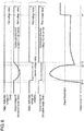
- FIG. 4 is a timing chart for explaining the operation of on-vehicle power supply device 6 according to the first exemplary embodiment of the present disclosure.
- on-vehicle power supply device 6 is disposed in vehicle 15 which makes up vehicle 14.
- Input unit 10 is connected with vehicle battery 17 via switch 16.
- output unit 11 is connected with load 13.
- vehicle battery 17 is connected with load 13 via transmission line 18.
- on-vehicle power supply device 6 has already been described with reference to FIG. 1 , and therefore description of on-vehicle power supply device 6 will be omitted.
- switch 16 When a passenger gets on vehicle 14 and turns on or off an activation switch (not illustrated) for activating vehicle 14, switch 16 is turned on or off. Furthermore, when the passenger switches switch 16 from off to on, vehicle 14 is activated, and switch 16 enters a connection state. Furthermore, controller 12 of on-vehicle power supply device 6 is also activated. The above corresponds to step A in the flowchart in FIG. 3A .
- controller 12 is connected with input unit 10, and detects the input voltage of input unit 10 at all times.
- the input voltage of input unit 10 may be detected. That controller 12 detects the input voltage of input unit 10 means that controller 12 detects the voltage of vehicle battery 17.
- controller 12 activates charge circuit 8.
- charge circuit 8 continuously or intermittently charges electricity storage 7 to a predetermined electricity storage voltage. The above corresponds to step B and step C in the flowchart in FIG. 3A .
- charge circuit 8 may include input unit 10.
- controller 12 detects the voltage of vehicle battery 17, and then charge circuit 8 charges electricity storage 7.
- charge circuit 8 charges electricity storage 7.
- an order of these operations may be reverse.
- on-vehicle power supply device 6 is not activated, either.
- the operation of on-vehicle power supply device 6 described below is an operation performed when vehicle battery 17 is in a normal state at a point of time at which vehicle 14 is activated. Furthermore, the operation of on-vehicle power supply device 6 described below is performed in a state where, after vehicle 14 is normally activated, vehicle 14 is being normally driven or can be driven.
- Controller 12 compares the input lower limit voltage and the input voltage by using the input voltage detected in step B.
- a value which cannot be taken while vehicle 14 normally operates is set to the input lower limit voltage.
- the input lower limit voltage may be set assuming a state where, for example, vehicle 14 causes a collision accident, and vehicle battery 17 becomes defective.
- the input lower limit voltage can be set to a value close to a low value such as 0 V to several V at which control unit 19 which controls entire vehicle 14 and load 13 cannot operate.
- controller 12 decides that vehicle 14 or vehicle battery 17 is in the normal state without encountering an accident, and the operation returns to step B.
- controller 12 detects the input voltage and compares and decides the input voltage and the input lower limit voltage at all times while vehicle 14 is in an activated state. The above corresponds to "No" in step D in the flowchart in FIG. 3A .
- discharge circuit 9 does not basically operate load 13.
- Discharge circuit 9 is connected with controller 12, and controller 12 controls an operation of discharge circuit 9.
- discharge circuit 9 operates to temporarily adjust an electricity storage amount of electricity storage 7.
- discharge circuit 9 only outputs weak power compared to a capacity of power which electricity storage 7 can store, and this weak power does not influence the operation of load 13.
- controller 12 decides that vehicle 14 and vehicle battery 17 are normal, power is supplied to control unit 19 and load 13 from vehicle battery 17 via transmission line 18.
- the present exemplary embodiment makes connection which enables power supply to load 13 from vehicle battery 17 at all times.
- load 13 actually includes a plurality of various loads.
- a load switch (not illustrated) which interlocks with switch 16 may be provided between vehicle battery 17 and load 13.
- Repetition of step B, step C and step D in FIG. 3A described herein is a normal mode, and is an operation in a case where vehicle 14 and vehicle battery 17 are normal as described above.
- step D proceeds from step D to step E.
- step E will be described as an "emergency power supply mode" in the present exemplary embodiment.
- Controller 12 compares the input lower limit voltage and the input voltage by using the input voltage detected in step B. When the input voltage takes a value less than or equal to the input lower limit voltage, controller 12 decides that vehicle 14 and vehicle battery 17 encounter an accident and are in an anomaly state ("emergency power supply mode"). This corresponds to "Yes” in step D in the flowchart of FIG. 3A .
- controller 12 decides that the input voltage takes the value less than or equal to the input lower limit voltage even though switch 16 is in a connected state (even though vehicle 14 is in an activated state), and controller 12 performs following control as the emergency power supply mode.
- controller 12 when controller 12 decides in step D that the input voltage takes the value less than or equal to the input lower limit voltage, controller 12 causes charge circuit 8 to stop charging electricity storage 7. Subsequently, controller 12 places discharge circuit 9 in a dischargeable state, and controls discharge circuit 9 to perform a discharging operation to drive load 13. When controller 12 decides that the input voltage takes the value less than or equal to the input lower limit voltage, discharge circuit 9 immediately performs the discharging operation.
- the discharging operation of discharge circuit 9 may be performed in response to that controller 12 receives from an outside a signal for causing discharge circuit 9 to operate as indicated in step D in FIG. 3B .
- a collision signal is used as one example of a received signal from the outside in FIG. 3B .
- Controller 12 sets the output instruction voltage to the first voltage value. Furthermore, discharge circuit 9 discharges power stored in electricity storage 7 such that the output instruction voltage is the first voltage value. Although not illustrated in FIGS. 1 and 2 , power for operating controller 12 is supplied from electricity storage 7 or discharge circuit 9 in the emergency power supply mode.
- discharge circuit 9 supplies a predetermined voltage to controller 12 and control unit 19 with small power compared to power immediately supplied to load 13. The above corresponds to step E in the flowchart in FIG. 3A .
- controller 12 detects the output voltage and the output current of discharge circuit 9.
- controller 12 may detect the output voltage and the output current of output unit 11 instead of an output of discharge circuit 9.
- controller 12 detects power (referred to as "output power” below) supplied to load 13.
- the power supplied to load 13 may be calculated by controller 12 by a product of the output voltage and the output current of discharge circuit 9 (or a product of the output voltage and the output current of output unit 11). The above corresponds to step F in the flowchart in FIG. 3A .
- discharge circuit 9 and output unit 11 have been described as different components, discharge circuit 9 may include output unit 11.
- controller 12 compares the power threshold and the output power by using the output voltage and the output current detected in step F.
- the power threshold is determined based on a maximum electricity storage amount of electricity storage 7, and a discharge time taken to supply power from discharge circuit 9 to load 13.
- a power threshold determining method is not limited to this. The above corresponds to step F in the flowchart in FIG. 3A .
- controller 12 instructs discharge circuit 9 to continuously operate by using the output instruction voltage as the first voltage value ("No" in step G).
- controller 12 instructs discharge circuit 9 to lower the output instruction voltage from the first voltage value to the second voltage value. This corresponds to G and step H in the flowchart in FIG. 3A .
- controller 12 instructs discharge circuit 9 to maintain output instruction voltage V1 at the first voltage value
- output instruction voltage V3 is changed from the first voltage value to output voltage V2
- FIG. 4 illustrates a change of output voltage V2 in a case where controller 12 instructs discharge circuit 9 to maintain output instruction voltage V1 at the first voltage value. Furthermore, FIG. 4 illustrates a change of output voltage V4 in a case where controller 12 instructs discharge circuit 9 to lower output instruction voltage V3 from the first voltage value to the second voltage value. Furthermore, FIG. 4 illustrates a change of output power W1 from output unit 11, too.
- discharge circuit 9 starts supplying power to load 13 at a timing of t0 to activate load 13 (electric motor).
- load 13 electric motor
- the operation of load 13 is not in a stationary state. That is, between t0 and t2, i.e., until the electric motor starts rotating at a constant speed after receiving a supply of power, a large current temporarily flows to load 13.
- electricity storage 7 and discharge circuit 9 there is a limit of power that can be supplied to load 13 by electricity storage 7 and discharge circuit 9.
- a decrease in output voltage V2 of discharge circuit 9 is a temporary phenomenon. Even when output power W1 temporarily increases, output power W1 decreases in the end, and, as output power W1 decreases, output voltage V2 returns to match with the first voltage value.
- discharge circuit 9 needs to supply a stable voltage to control unit 19 and controller 12 in some cases.
- the output voltage of discharge circuit 9 in the emergency power supply mode needs to maintain a higher voltage at all times than control unit drive limit voltage VLo (referred to as limit voltage VLo below).
- limit voltage VLo control unit drive limit voltage
- controller 12 controls discharge circuit 9 to maintain output instruction voltage V1 at the first voltage value irrespective of such a restriction, it is likely that output voltage V2 of discharge circuit 9 temporarily lowers substantially to maintain the discharge power, and output voltage V2 lowers to a value lower than limit voltage VLo.
- controller 12 performs control to cause discharge circuit 9 to lower output instruction voltage V3 from the first voltage value to the second voltage value.
- a large current flows from output unit 11 to supply high power to load 13.
- output voltage V4 of discharge circuit 9 is concerned to temporarily lower.
- output instruction voltage V3 is lowered to the second voltage value, and therefore a permitted amount of the output current in discharge circuit 9 becomes large.
- a region in which the output voltage of discharge circuit 9 temporarily lowers substantially due to control for maintaining output instruction voltage V1 of discharge circuit 9 at the first voltage value is indicated by hatching output voltage V2.
- a region in which output voltage V4 of discharge circuit 9 temporarily lowers substantially due to control for lowering output instruction voltage V3 of discharge circuit 9 from the first voltage value to the second voltage value is indicated by hatching output voltage V4.
- a value obtained by integrating the insufficient voltage, and a value obtained by integrating a value obtained by lowering the standards of the output instruction voltage may be matched substantially. Consequently, even when the large current instantaneously flows to load 13, it is possible to substantially prevent a decrease in output voltage V4 of discharge circuit 9 caused by the large current. Alternatively, even when the large current instantaneously flows to load 13, it is possible to prevent output voltage V4 of discharge circuit 9 from lowering to less than or equal to the second voltage value.
- the timing chart in FIG. 4 illustrates the second voltage value as a fixed value, yet is influenced by load 13 in some cases and therefore pulsates in some cases.
- controller 12 performs control according to the timing chart in FIG. 4 in step G and step H in the flowchart in FIG. 3A , so that on-vehicle power supply device 6 can stably operate. That is, an auxiliary electricity storage element (e.g., auxiliary electricity storage element 4 in FIG. 9 ) is not provided to electricity storage 7, and electricity storage 7 and discharge circuit 9 output stable output voltage V4. Hence, on-vehicle power supply device 6 can be miniaturized.
- auxiliary electricity storage element e.g., auxiliary electricity storage element 4 in FIG. 9
- controller 12 lowers output instruction voltage V3 from the first voltage value to the second voltage value.
- control and operation may not be performed.
- control of controller 12 lowers output voltage V4 of discharge circuit 9 from the first voltage to the second voltage.
- controller 12 makes the output instruction voltage the first voltage value. However, this may be replaced to read that "controller 12 performs control to output the first voltage value to discharge circuit 9". In still another example, it has been described that "controller 12 makes output instruction voltage V3 the second voltage value”. However, this description may be replaced to read that "controller 12 causes discharge circuit 9 to output the second voltage value”.
- FIG. 4 illustrates that, when output instruction voltage V3 lowers to the second voltage value in the emergency power supply mode, output voltage V4 shows a waveform similar to the output instruction voltage for ease of description. However, output voltage V4 may fluctuate a little in a period from t1 to t3. Output voltage V4 maintains a higher voltage than limit voltage VLo in the period from t1 to t3.
- a trajectory of a fluctuation of output power W1 substantially corresponds to a trajectory of a torque fluctuation of the electric motor which is load 13. Furthermore, the trajectory of output power W1 passes a maximum value and starts lowering as the time passes, and becomes lower than power threshold Wt at a timing of t2. As described below, load 13 becomes close to a stationary operation state at a timing of t3 after the timing of t2, then the torque further lowers, and output power W1 becomes lower than power threshold Wt at the timing of t3.
- Output power W1 lowers when the operation (mainly rotation) of the electric motor which is load 13 enters the stationary state or becomes close to the stationary state. After the operation of load 13 enters the stationary state, large output power is not requested. Hence, at a timing at which it is possible to regard that load 13 enters the stationary state, output instruction voltage V3 to discharge circuit 9 may be returned from the second voltage value to the first voltage value. Consequently, output voltage V4 from discharge circuit 9 becomes high at all times with a margin with respect to limit voltage VLo. Consequently, discharge circuit 9 can stably supply a drive voltage to control unit 19 and controller 12.
- the timing at which output instruction voltage V3 to discharge circuit 9 is returned from the second voltage value to the first voltage value may come after t2 of a timing at which output power W1 becomes smaller again than power threshold Wt used before.
- the timing at which output instruction voltage V3 to discharge circuit 9 is returned from the second voltage value to the first voltage value may be t3 which passes a desired period from the timing of t2.
- output instruction voltage V3 to discharge circuit 9 is returned from the second voltage value to the first voltage value at the timing of t3. The above corresponds to step I and step J in the flowchart in FIG. 3A .
- controller 12 returns output instruction voltage V3 from the second voltage value to the first voltage value in this description. That is, the operation has been described from the aspect related to the instruction of controller 12. By contrast with this, the operation may be described from the aspect related to the operation of discharge circuit 9.
- the control and the operation described to read that "controller 12 returns the output instruction voltage from the second voltage value to the first voltage value" may be replaced with that "the output voltage of discharge circuit 9 returns from the second voltage to the first voltage under control of controller 12".
- the operation in the stationary state of load 13 continues by a timing of t4. Furthermore, at the timing of t4, the operation of the electric motor which is load 13 reaches a limit of an operation range. In other words, when the electric motor reaches a rotation limit from a state where the electric motor is rotating, a large current flows again to load 13, and large power is supplied. At t4 which is this timing or subsequent to t4, the main operation of on-vehicle power supply device 6 has been finished. Hence, after the timing of t4, output instruction voltage V3 does not need to be changed to other standards.
- On-vehicle power supply device 6 can more accurately decide whether or not the anomaly state of vehicle 14 occurs. As a result, on-vehicle power supply device 6 can operate in the emergency power supply mode at a necessary timing.
- FIG. 5 is a block diagram illustrating a configuration of vehicle 14 on which on-vehicle power supply device 6 according to the second exemplary embodiment is mounted.
- the same components between a configuration of vehicle 14 illustrated in FIG. 2 and the configuration of vehicle 14 illustrated in FIG. 5 will be assigned the same reference signs, and description of the components will be omitted.
- FIG. 3B is a flowchart for explaining an operation of an on-vehicle power supply device according to the second exemplary embodiment.
- a step different between a flowchart illustrated in FIG. 3A and the flowchart illustrated in FIG. 3B is only step D.
- on-vehicle power supply device 6 is provided with collision signal receiver 20 connected with controller 12. Controller 12 detects an input voltage of input unit 10 at all times. In addition, controller 12 may detect the input voltage from charge circuit 8. Furthermore, when controller 12 detects (1) that the input voltage has become lower than an input lower limit voltage, (2) detects reception of a collision signal via collision signal receiver 20, and detects at least one of (1) and (2), in step D, the processing proceeds to "YES", and on-vehicle power supply device 6 operates in an emergency power supply mode similarly to the first exemplary embodiment (step E to step H). Furthermore, similarly to the first exemplary embodiment, according to the second exemplary embodiment, step I and step J may be performed.
- controller 12 receives power for an operation from electricity storage 7 or discharge circuit 9 in the emergency power supply mode although not illustrated in FIG. 5 .
- Controller 12 causes charge circuit 8 to stop charging electricity storage 7, makes an output instruction voltage to discharge circuit 9 the first voltage value (step E), and causes discharge circuit 9 to start discharging power of electricity storage 7. Furthermore, when output power W1 becomes larger than power threshold Wt, controller 12 lowers the output instruction voltage to discharge circuit 9 from the first voltage value to the second voltage value (step H).
- on-vehicle power supply device 6 can more accurately decide whether or not the anomaly state of vehicle 14 occurs. As a result, on-vehicle power supply device 6 can operate in the emergency power supply mode at a necessary timing.
- collision signal receiver 20 is connected with collision detector 21 disposed in vehicle body 15. Therefore, when vehicle 14 encounters an accident, a collision signal is transmitted from collision detector 21 to controller 12 via collision signal receiver 20.
- collision signal receiver 20 and controller 12 indicate individual components for ease of description, collision signal receiver 20 may be included in controller 12.
- the present exemplary embodiment does not describe a normal mode of on-vehicle power supply device 6 in particular. However, when controller 12 detects that the input voltage is higher than the input lower limit voltage and controller 12 does not detect reception of the collision signal via collision signal receiver 20, on-vehicle power supply device 6 operates in the normal mode.
- controller 12 causes discharge circuit 9 to lower output instruction voltage V3 from the first voltage value to the second voltage value.
- a timing at which the output instruction voltage to discharge circuit 9 is lowered from the first voltage value to the second voltage value is decided by comparing the output power and the power threshold as indicated in step G in FIGS. 3A and 3B .
- the timing may be decided by comparing output current I1 and current threshold It.
- the output current may be used for the output power
- the current threshold may be used for the power threshold.
- load 13 illustrated in FIG. 6 is an electric motor.
- discharge circuit 9 starts supplying power to load 13 at a timing of t0 to activate load 13.
- the current starts flowing to load 13 at the timing of t0.
- a large current indicated as output current I1 in FIG. 6 ) temporarily flows to load 13.
- the output voltage does not start lowering at the timing of t0.
- output voltage V4 starts lowering when power which can be supplied from electricity storage 7 and discharge circuit 9 to load 13 reaches a limit. That is, output voltage V4 does not immediately start lowering when output current I1 flows, but starts at a timing of t1 which is a timing at which output current I1 is more than or equal to current threshold It. Consequently, controller 12 can accurately decide whether or not to cause discharge circuit 9 to lower output instruction voltage V3 from the first voltage value to the second voltage value based on output current I1 and current threshold It.
- controller 12 for output instruction voltage V3 Next, another control method of controller 12 for output instruction voltage V3 will be described with reference to FIG. 7 .
- controller 12 lowers output instruction voltage V3 to discharge circuit 9 from the first voltage value to the second voltage value (step H).
- controller 12 when output current I1 becomes larger than current threshold It in the emergency power supply mode as illustrated in FIG. 7 , controller 12 performs control for causing discharge circuit 9 to sequentially lower the output instruction voltage continuously or stepwise from the first voltage value to the second voltage value according to a value of the output current.
- output current I1 and current threshold It have been used and described.
- output power W1 and power threshold Wt may be used instead of output current I1 and current threshold It for decision in step G similarly to FIG. 3A .
- controller 12 performs control for causing discharge circuit 9 to gradually decrease the output instruction voltage to the second voltage value at t11 of a timing at which output current I1 maximizes. Consequently, while output voltage V4 to be actually detected gradually decreases substantially in synchronization with output instruction voltage V3, it is possible to shorten a period in which the output voltage to be detected becomes close to limit voltage VLo. As a result, output voltage V4 from discharge circuit 9 becomes higher than limit voltage VLo. Consequently, discharge circuit 9 can stably supply a drive voltage to control unit 19 and controller 12.
- vehicle 14 on which on-vehicle power supply device 6 is mounted according to the fourth exemplary embodiment of the present disclosure will be described with reference to FIG. 8 .
- on-vehicle power supply device 6 illustrated in FIG. 8 further includes residual detector 23 which detects a residual electricity storage amount of electricity storage 7.
- the other components are the same, and therefore will be assigned the same reference signs, and description of the components will be omitted.
- Residual detector 23 can detect the residual electricity storage amount of electricity storage 7, and a detection result is input to controller 12. Furthermore, controller 12 determines a value of power threshold Wt based on the residual electricity storage amount input from residual detector 23.
- discharge circuit 9 is controlled by controller 12 to output power corresponding to the residual electricity storage amount of electricity storage 7, so that on-vehicle power supply device 6 can stably supply power.
- controller 12 in a case where controller 12 operates on-vehicle power supply device 6 in an emergency power supply mode, when output power W1 of output current I1 and output voltage V4 becomes larger than power threshold Wt, controller 12 performs control for causing discharge circuit 9 to lower output instruction voltage V3 from the first voltage value to the second voltage value. In addition, when output current I1 becomes larger than current threshold It, controller 12 may perform control for causing discharge circuit 9 to lower output instruction voltage V3 from the first voltage value to the second voltage value.
- a timing at which controller 12 lowers output instruction voltage V3 in the above exemplary embodiments may be determined as t1 illustrated in FIG. 4 in association with power threshold Wt and current threshold It.
- controller 12 may lower output instruction voltage V3, set an upper limit value to output current I1 and operate on-vehicle power supply device 6 in the emergency power supply mode.
- the upper limit value set to output current I1 is a value at which an electric motor can start rotating at above output instruction voltage V3, i.e., a value larger than a value at which load 13 can operate when load 13 is the electric motor.
- on-vehicle power supply device 6 has capability which can output power of 200 W at the current of 20A and the voltage of 10 V when electricity storage 7 is fully charged.
- output power W1 is more than or equal to power threshold Wt
- charge circuit 8 may be controlled by controller 12 to send an output at the current of 10 A and the voltage of 8 V. 8 V which is the output voltage may be the output instruction voltage of controller 12.
- controller 12 lowers output instruction voltage V3, and controller 12 further suppresses output current I1 to less than or equal to the upper limit value.
- controller 12 lowers output instruction voltage V3, output voltage V4 from discharge circuit 9 easily follows output instruction voltage V3 reliably. Furthermore, output voltage V4 of discharge circuit 9 easily maintains a higher voltage than limit voltage VLo.
- controller 12 may set output power W1 according to the residual electricity storage amount of electricity storage 7, and discharge circuit 9 may be controlled by controller 12 to output power set according to the residual electricity storage amount. Consequently, on-vehicle power supply device 6 can stably supply power with a little fluctuation in the emergency power supply mode.
- power for operating controller 12 is supplied from electricity storage 7 or discharge circuit 9 in the emergency power supply mode.
- examples of load 13 according to the above exemplary embodiments include a motor which needs a temporarily large current during activation.
- Load 13 is, for example, a motor which operates to unlock a door, or a motor which operates to unlock a door latch.
- controller 12 is described as the independent element.
- the function of controller 12 may be dispersed and implemented in electricity storage 7, discharge circuit 9, charge circuit 8, input unit 10 and output unit 11.
- On-vehicle power supply device 6 includes: electricity storage 7; charge circuit 8 which is provided on a charging route of electricity storage 7, and charges electricity storage 7 with power; discharge circuit 9 which is provided on an output route of electricity storage 7, and discharges the power of electricity storage 7; input unit 10 which is connected with charge circuit 8; output unit 11 which is connected with discharge circuit 9; and controller 12 that detects an input voltage of input unit 10, an output current of output unit 11, and an output voltage of output unit 11, and controls charge circuit 8 and discharge circuit 9, and, when controller 12 decides that an emergency operation condition is satisfied, controllers 12 causes the charge circuit 8 to stop charging power to electricity storage 7, then sets output instruction voltage V3 which is a target voltage value of an output of discharge circuit 9 to a first voltage value, controller 12 further causes discharge circuit 9 to discharges the power charged in electricity storage 7, and, when the power output from discharge circuit 9 is higher than power threshold Wt, the controller lowers output instruction voltage V3 from a first voltage value to a second voltage value.
- the emergency operation condition when controller 12 detects that the input voltage has become lower than an input lower limit voltage, the emergency operation condition may be satisfied.
- On-vehicle power supply device 6 may further include collision signal receiver 20 which is connected with controller 12 and receives a collision signal, and, when collision signal receiver 20 receives the collision signal, the emergency operation condition may be satisfied.
- On-vehicle power supply device 6 may further increase output instruction voltage V3 from the second voltage value to the first voltage value when the power output from discharge circuit 9 becomes higher than power threshold Wt and then becomes lower than power threshold Wt again.
- on-vehicle power supply device 6 may compare the power output from discharge circuit 9 and power threshold Wt by using a current value.
- controller 12 when lowering output instruction voltage V3 from the first voltage value to the second voltage value, controller 12 may lower output instruction voltage V3 from the first voltage value to the second voltage value continuously or stepwise.
- on-vehicle power supply device 6 may further include residual detector 23 which detects a residual electricity storage amount of electricity storage 7, and power threshold Wt may be determined based on the residual electricity storage amount of electricity storage 7 detected by the residual detector 23.
- on-vehicle power supply device 6 includes: electricity storage 7; charge circuit 8 which is provided on a charging route of electricity storage 7, and charges electricity storage 7 with power; discharge circuit 9 which is provided on an output route of electricity storage 7, and discharges the power of electricity storage 7; input unit 10 which is connected with charge circuit 8; output unit 11 which is connected with discharge circuit 9; and controller 12 that detects an input voltage of input unit 10, an output current of output unit 11, and an output voltage of output unit 11, and controls charge circuit 8 and discharge circuit 9, and, when controller 12 decides that an emergency operation condition is satisfied, charge circuit 8 stops charging of electricity storage 7, then discharge circuit 9 discharges the power at a first voltage, controller 12 further causes discharge circuit 9 to discharge the power charged in electricity storage 7, and, when the power output from discharge circuit 9 becomes higher than power threshold Wt, discharge circuit 9 discharges the power at a second voltage value smaller than the first voltage value.
- Vehicle 14 includes: on-vehicle power supply device 6 according to one of the above; vehicle body 15 on which on-vehicle power supply device 6 is mounted; and vehicle battery 17 which is mounted on vehicle body 15 and supplies power to on-vehicle power supply device 6.
- the on-vehicle power supply device lowers the output instruction voltage by a predetermined value when large output power is necessary in, for example, the emergency power supply mode in particular. Consequently, temporary pulsation of an output voltage which occurs as the output power reaches a supply limit, in other words, temporary pulsation of an output voltage which occurs due to an influence from the load is suppressed. Consequently, a significant fluctuation of a output voltage is alleviated. Consequently, the on-vehicle power supply device can output a stable voltage without additionally providing an auxiliary electricity storage element. As a result, the on-vehicle power supply device can stably operate, and realize miniaturization at the same time.
- the on-vehicle power supply device provides an effect that it is possible to perform a stable operation and realize miniaturization at the same time, and is useful for various electronic devices.
Landscapes
- Engineering & Computer Science (AREA)
- Power Engineering (AREA)
- Mechanical Engineering (AREA)
- Transportation (AREA)
- Life Sciences & Earth Sciences (AREA)
- Sustainable Development (AREA)
- Sustainable Energy (AREA)
- Business, Economics & Management (AREA)
- Emergency Management (AREA)
- Charge And Discharge Circuits For Batteries Or The Like (AREA)
- Electric Propulsion And Braking For Vehicles (AREA)
Abstract
Description
- The present disclosure relates to an on-vehicle power supply device and an on-vehicle power supply device vehicle.
- A conventional on-vehicle power supply device will be described below with reference to the drawings.
FIG. 9 is a circuit block diagram illustrating a configuration of the conventional on-vehicle power supply device, andoutput unit 30 of on-vehiclepower supply device 1 is connected withload 2. On-vehiclepower supply device 1 includeselectricity storage element 3, auxiliaryelectricity storage element 4 andswitch unit 5.Electricity storage element 3 is connected withoutput unit 30 viaswitch unit 5, and auxiliaryelectricity storage element 4 is connected with an output ofswitch unit 5. That is, auxiliaryelectricity storage element 4 is connected withoutput unit 30. When the voltage ofelectricity storage element 3 is normal,switch unit 5 causeselectricity storage element 3 to supply power to load 2. Simultaneously,switch unit 5 operates such thatelectricity storage element 3 charges auxiliaryelectricity storage element 4. - On the other hand, when the voltage of
electricity storage element 3 lowers,switch unit 5 discharges power of auxiliaryelectricity storage element 4 and superimposes the voltage of auxiliaryelectricity storage element 4 on the voltage ofelectricity storage element 3. Both ofelectricity storage element 3 and auxiliaryelectricity storage element 4 supply power to load 2. According to this configuration, even when the voltage ofelectricity storage element 3 lowers, on-vehiclepower supply device 1 can supply power to load 2 at a stable voltage. - It should be noted that, for example,
PTL 1 is known as a prior art document containing information related to this application. -
- An on-vehicle power supply device according to one aspect of the present disclosure includes: an electricity storage; a charge circuit that is provided on a charging route of the electricity storage, and charges the electricity storage with power; a discharge circuit that is provided on an output route of the electricity storage, and discharges the power of the electricity storage; an input unit that is connected with the charge circuit; an output unit that is connected with the discharge circuit; and a controller that detects an input voltage of the input unit, an output current of the output unit, and an output voltage of the output unit, and controls the charge circuit and the discharge circuit, and, when the controller decides that an emergency operation condition is satisfied, the controllers causes the charge circuit to stop charging the power to the electricity storage, then sets an output instruction voltage that is a target voltage value of an output of the discharge circuit to a first voltage value, the controller further causes the discharge circuit to discharge the power charged in the electricity storage, and, when the power output from the discharge circuit becomes higher than a power threshold, the controller lowers the output instruction voltage from the first voltage value to a second voltage value.
- Furthermore, a vehicle according to the present disclosure includes: the on-vehicle power supply device according to the above one aspect; a vehicle body on which the on-vehicle power supply device is mounted; and a vehicle battery that is mounted on the vehicle body and supplies power to the on-vehicle power supply device.
-
-
FIG. 1 is a circuit block diagram illustrating a configuration of an on-vehicle power supply device according to a first exemplary embodiment of the present disclosure. -
FIG. 2 is a circuit block diagram illustrating a configuration of a vehicle on which the on-vehicle power supply device according to the first exemplary embodiment of the present disclosure is mounted. -
FIG. 3A is a flowchart for explaining an operation of the on-vehicle power supply device according to the first exemplary embodiment of the present disclosure. -
FIG. 3B is a flowchart for explaining an operation of an on-vehicle power supply device according to a second exemplary embodiment of the present disclosure. -
FIG. 3C is a flowchart for explaining an operation of an on-vehicle power supply device according to an exemplary embodiment of the present disclosure. -
FIG. 3D is a flowchart for explaining the operation of the on-vehicle power supply device according to the exemplary embodiment of the present disclosure. -
FIG. 4 is a timing chart for explaining the operation of the on-vehicle power supply device according to the first exemplary embodiment of the present disclosure. -
FIG. 5 is a block diagram illustrating a configuration of a vehicle on which the on-vehicle power supply device according to the second exemplary embodiment of the present disclosure is mounted. -
FIG. 6 is a timing chart for explaining the operation of the on-vehicle power supply device according to the second exemplary embodiment of the present disclosure. -
FIG. 7 is a flowchart illustrating the operation of the on-vehicle power supply device according to the third exemplary embodiment of the present disclosure. -
FIG. 8 is a block diagram illustrating a configuration of a vehicle on which the on-vehicle power supply device according to a fourth exemplary embodiment of the present disclosure is mounted. -
FIG. 9 is a circuit block diagram illustrating a conventional on-vehicle power supply device. - On-vehicle
power supply device 1 described with reference toFIG. 9 needs to include auxiliaryelectricity storage element 4 that makes up for a decrease when the voltage ofelectricity storage element 3 decreases. Hence, a number of elements that make up on-vehiclepower supply device 1 increases. As a result, on-vehiclepower supply device 1 becomes large. - On-vehicle
power supply device 6 according to the present disclosure described below can stably operate, and realize miniaturization. - The first exemplary embodiment of the present disclosure will be described below with reference to the drawings.
-
FIG. 1 is a circuit block diagram illustrating a configuration of on-vehiclepower supply device 6 according to the first exemplary embodiment of the present disclosure. On-vehiclepower supply device 6 includeselectricity storage 7,charge circuit 8,discharge circuit 9,input unit 10,output unit 11 andcontroller 12. -
Charge circuit 8 is provided on a charging route ofelectricity storage 7, and can chargeelectricity storage 7 with power.Discharge circuit 9 is provided on an output route ofelectricity storage 7, and discharges the power ofelectricity storage 7.Input unit 10 is connected withcharge circuit 8, andoutput unit 11 is connected withdischarge circuit 9.Controller 12 detects an input voltage ofinput unit 10, an output current ofoutput unit 11 and an output voltage ofoutput unit 11, and controls operations ofcharge circuit 8 anddischarge circuit 9. -
FIG. 1 illustrates power supply routes as bold lines, and signal transmission routes as thin lines. For example, the power supply route which connectsinput unit 10 andcharge circuit 8 is illustrated as the bold line, and the signal transmission route which connectsinput unit 10 andcontroller 12 is illustrated as a thin line. However, whether power transmitted through the power supply routes or the signal transmission routes is high or low is just an indication, and each of the bold lines and the thin lines is electrically connected likewise. - When
controller 12 detects that an input voltage ofinput unit 10 is more than or equal to an input lower limit voltage,controller 12 decides that normal operation conditions are satisfied. Furthermore,controller 12controls charge circuit 8 such thatcharge circuit 8 continuously or intermittently chargeselectricity storage 7 in order thatoutput unit 11 reaches a predetermined electricity storage voltage. A state where the input voltage is more than or equal to the input lower limit voltage will be referred to as a "normal mode" below. - On the other hand, when
controller 12 detects that the input voltage is lower than the input lower limit voltage,controller 12 decides that emergency operation conditions are satisfied. Furthermore,controller 12 performs control to causecharge circuit 8 to stop chargingelectricity storage 7, and then discharge power fromelectricity storage 7 todischarge circuit 9. In this case,controller 12 instructs an output instruction voltage which is a target voltage value of an output ofdischarge circuit 9 todischarge circuit 9, and starts discharging power fromelectricity storage 7 todischarge circuit 9. The output instruction voltage in this case is a "first voltage value". A state where the input voltage is lower than the input lower limit voltage will be referred to as an "emergency power supply mode" below. Subsequently, when output power of the output current and the output voltage is more than or equal to a power threshold,controller 12 instructsdischarge circuit 9 to lower the output instruction voltage from the first voltage value to the second voltage value. Details of a change in the voltage will be described below with reference toFIG. 4 . - As described above, when large output power is necessary in the emergency power supply mode, on-vehicle
power supply device 6 lowers the output instruction voltage from the first voltage value to the second voltage value. According to this configuration, temporary pulsation of a voltage which occurs as the output power reaches a supply limit, in other words, temporary pulsation of a voltage which occurs due to an influence fromload 13 connected withoutput unit 11 is suppressed. Consequently, a fluctuation of a high output voltage is alleviated. On-vehiclepower supply device 6 can output a stable voltage without additionally providing an auxiliary electricity storage element (e.g.,electricity storage element 3 illustrated inFIG. 9 ). As a result, on-vehiclepower supply device 6 can stably operate, and realize miniaturization at the same time. - Next, details of a configuration and an operation of on-vehicle
power supply device 6 will be described with reference to the drawings.FIG. 2 is a block diagram illustrating a configuration ofvehicle 14 on which on-vehiclepower supply device 6 according to the first exemplary embodiment of the present disclosure is mounted.FIG. 3A is a flowchart for explaining the operation of on-vehiclepower supply device 6 according to the first exemplary embodiment of the present disclosure, andFIG. 4 is a timing chart for explaining the operation of on-vehiclepower supply device 6 according to the first exemplary embodiment of the present disclosure. - As illustrated in
FIG. 2 , on-vehiclepower supply device 6 is disposed invehicle 15 which makes upvehicle 14.Input unit 10 is connected withvehicle battery 17 viaswitch 16. Furthermore,output unit 11 is connected withload 13. Furthermore,vehicle battery 17 is connected withload 13 viatransmission line 18. In addition, on-vehiclepower supply device 6 has already been described with reference toFIG. 1 , and therefore description of on-vehiclepower supply device 6 will be omitted. - When a passenger gets on
vehicle 14 and turns on or off an activation switch (not illustrated) for activatingvehicle 14,switch 16 is turned on or off. Furthermore, when the passenger switches switch 16 from off to on,vehicle 14 is activated, and switch 16 enters a connection state. Furthermore,controller 12 of on-vehiclepower supply device 6 is also activated. The above corresponds to step A in the flowchart inFIG. 3A . - Next,
controller 12 is connected withinput unit 10, and detects the input voltage ofinput unit 10 at all times. In addition, by connectingcontroller 12 withcharge circuit 8 and detecting the input voltage ofcharge circuit 8, the input voltage ofinput unit 10 may be detected. Thatcontroller 12 detects the input voltage ofinput unit 10 means thatcontroller 12 detects the voltage ofvehicle battery 17. Furthermore, whencontroller 12 detects a voltage ofvehicle battery 17,controller 12 activatescharge circuit 8. Furthermore,charge circuit 8 continuously or intermittently chargeselectricity storage 7 to a predetermined electricity storage voltage. The above corresponds to step B and step C in the flowchart inFIG. 3A . - In addition, although the present exemplary embodiment has described
charge circuit 8 andinput unit 10 as individual elements,charge circuit 8 may includeinput unit 10. - In addition, according to the present exemplary embodiment,
controller 12 detects the voltage ofvehicle battery 17, and then chargecircuit 8charges electricity storage 7. However, an order of these operations may be reverse. - Furthermore, if
vehicle battery 17 is in an anomaly state during activation ofvehicle 14,vehicle 14 is not normally activated. Hence, whenvehicle 14 is not normally activated, on-vehiclepower supply device 6 is not activated, either. The operation of on-vehiclepower supply device 6 described below is an operation performed whenvehicle battery 17 is in a normal state at a point of time at whichvehicle 14 is activated. Furthermore, the operation of on-vehiclepower supply device 6 described below is performed in a state where, aftervehicle 14 is normally activated,vehicle 14 is being normally driven or can be driven. - Next, step D will be described.
Controller 12 compares the input lower limit voltage and the input voltage by using the input voltage detected in step B. A value which cannot be taken whilevehicle 14 normally operates is set to the input lower limit voltage. The input lower limit voltage may be set assuming a state where, for example,vehicle 14 causes a collision accident, andvehicle battery 17 becomes defective. In other words, the input lower limit voltage can be set to a value close to a low value such as 0 V to several V at whichcontrol unit 19 which controlsentire vehicle 14 andload 13 cannot operate. - When the input voltage takes a value larger than the input lower limit voltage,
controller 12 decides thatvehicle 14 orvehicle battery 17 is in the normal state without encountering an accident, and the operation returns to step B. Whencontroller 12 detects the input voltage and compares and decides the input voltage and the input lower limit voltage at all times whilevehicle 14 is in an activated state. The above corresponds to "No" in step D in the flowchart inFIG. 3A . - In addition, while
controller 12 decides thatvehicle 14 andvehicle battery 17 are normal,discharge circuit 9 does not basically operateload 13.Discharge circuit 9 is connected withcontroller 12, andcontroller 12 controls an operation ofdischarge circuit 9. There is a case where, whilecontroller 12 decides thatvehicle 14 andvehicle battery 17 are normal,discharge circuit 9 operates to temporarily adjust an electricity storage amount ofelectricity storage 7. In this case,discharge circuit 9 only outputs weak power compared to a capacity of power whichelectricity storage 7 can store, and this weak power does not influence the operation ofload 13. Furthermore, whencontroller 12 decides thatvehicle 14 andvehicle battery 17 are normal, power is supplied to controlunit 19 and load 13 fromvehicle battery 17 viatransmission line 18. The present exemplary embodiment makes connection which enables power supply to load 13 fromvehicle battery 17 at all times. However, load 13 actually includes a plurality of various loads. Hence, a load switch (not illustrated) which interlocks withswitch 16 may be provided betweenvehicle battery 17 andload 13. - Repetition of step B, step C and step D in
FIG. 3A described herein is a normal mode, and is an operation in a case wherevehicle 14 andvehicle battery 17 are normal as described above. - Next, an operation in a case where the processing proceeds from step D to step E will be described. A case where the processing proceeds to step E will be described as an "emergency power supply mode" in the present exemplary embodiment.
-
Controller 12 compares the input lower limit voltage and the input voltage by using the input voltage detected in step B. When the input voltage takes a value less than or equal to the input lower limit voltage,controller 12 decides thatvehicle 14 andvehicle battery 17 encounter an accident and are in an anomaly state ("emergency power supply mode"). This corresponds to "Yes" in step D in the flowchart ofFIG. 3A . - When
controller 12 decides that the input voltage takes the value less than or equal to the input lower limit voltage even thoughswitch 16 is in a connected state (even thoughvehicle 14 is in an activated state), andcontroller 12 performs following control as the emergency power supply mode. - First, when
controller 12 decides in step D that the input voltage takes the value less than or equal to the input lower limit voltage,controller 12 causescharge circuit 8 to stop chargingelectricity storage 7. Subsequently,controller 12 places dischargecircuit 9 in a dischargeable state, and controls dischargecircuit 9 to perform a discharging operation to driveload 13. Whencontroller 12 decides that the input voltage takes the value less than or equal to the input lower limit voltage,discharge circuit 9 immediately performs the discharging operation. - In addition, although the discharging operation of
discharge circuit 9 is started when it is decided that the input voltage takes the value less than or equal to the input lower limit voltage in the present exemplary embodiment, the discharging operation ofdischarge circuit 9 may be performed in response to thatcontroller 12 receives from an outside a signal for causingdischarge circuit 9 to operate as indicated in step D inFIG. 3B . As one example of a received signal from the outside inFIG. 3B , a collision signal is used. - In this regard, a target voltage value of the voltage which is output by
discharge circuit 9 to driveload 13 will be referred to as an "output instruction voltage".Controller 12 sets the output instruction voltage to the first voltage value. Furthermore,discharge circuit 9 discharges power stored inelectricity storage 7 such that the output instruction voltage is the first voltage value. Although not illustrated inFIGS. 1 and2 , power for operatingcontroller 12 is supplied fromelectricity storage 7 ordischarge circuit 9 in the emergency power supply mode. - Furthermore, when
controller 12 decides that the input voltage takes the value less than or equal to the input lower limit voltage to maintain the functions ofcontroller 12 andcontrol unit 19,discharge circuit 9 supplies a predetermined voltage tocontroller 12 andcontrol unit 19 with small power compared to power immediately supplied to load 13. The above corresponds to step E in the flowchart inFIG. 3A . - Next,
controller 12 detects the output voltage and the output current ofdischarge circuit 9. In addition,controller 12 may detect the output voltage and the output current ofoutput unit 11 instead of an output ofdischarge circuit 9. In other words,controller 12 detects power (referred to as "output power" below) supplied to load 13. In this regard, the power supplied to load 13 may be calculated bycontroller 12 by a product of the output voltage and the output current of discharge circuit 9 (or a product of the output voltage and the output current of output unit 11). The above corresponds to step F in the flowchart inFIG. 3A . In this regard, althoughdischarge circuit 9 andoutput unit 11 have been described as different components,discharge circuit 9 may includeoutput unit 11. - Next,
controller 12 compares the power threshold and the output power by using the output voltage and the output current detected in step F. The power threshold is determined based on a maximum electricity storage amount ofelectricity storage 7, and a discharge time taken to supply power fromdischarge circuit 9 to load 13. In addition, a power threshold determining method is not limited to this. The above corresponds to step F in the flowchart inFIG. 3A . When the output power is less than or equal to the power threshold in step G,controller 12 instructsdischarge circuit 9 to continuously operate by using the output instruction voltage as the first voltage value ("No" in step G). - On the other hand, when the output power is higher than the power threshold,
controller 12 instructsdischarge circuit 9 to lower the output instruction voltage from the first voltage value to the second voltage value. This corresponds to G and step H in the flowchart inFIG. 3A . - Hereinafter, a case where
controller 12 instructsdischarge circuit 9 to maintain output instruction voltage V1 at the first voltage value, and a case where output instruction voltage V3 is changed from the first voltage value to output voltage V2 will be compared with reference toFIG. 4 . -
FIG. 4 illustrates a change of output voltage V2 in a case wherecontroller 12 instructsdischarge circuit 9 to maintain output instruction voltage V1 at the first voltage value. Furthermore,FIG. 4 illustrates a change of output voltage V4 in a case wherecontroller 12 instructsdischarge circuit 9 to lower output instruction voltage V3 from the first voltage value to the second voltage value. Furthermore,FIG. 4 illustrates a change of output power W1 fromoutput unit 11, too. - Hereinafter, an example where
load 13 is an electric motor will be described. As indicated by W1 inFIG. 4 ,discharge circuit 9 starts supplying power to load 13 at a timing of t0 to activate load 13 (electric motor). At a timing from t0 to t2, the operation ofload 13 is not in a stationary state. That is, between t0 and t2, i.e., until the electric motor starts rotating at a constant speed after receiving a supply of power, a large current temporarily flows to load 13. Furthermore, there is a limit of power that can be supplied to load 13 byelectricity storage 7 anddischarge circuit 9. - Hence, when control is performed to instruct
discharge circuit 9 to maintain output instruction voltage V1 at the first voltage value as illustrated inFIG. 4 , and a large current flows to instantaneously supply high power to load 13, if the value of the output current ofdischarge circuit 9 becomes too large,discharge circuit 9 continues operating in a state where discharge power is maintained. Hence, to maintain the discharge power, output voltage V2 ofdischarge circuit 9 temporarily lowers substantially in some cases. That is, output voltage V2 output fromdischarge circuit 9 and detected byoutput unit 11, and output instruction voltage V1 instructed to dischargecircuit 9 bycontroller 12 take different values, and output voltage V2 becomes lower than output instruction voltage V1. - A decrease in output voltage V2 of
discharge circuit 9 is a temporary phenomenon. Even when output power W1 temporarily increases, output power W1 decreases in the end, and, as output power W1 decreases, output voltage V2 returns to match with the first voltage value. - However, in the emergency power supply mode that on-vehicle
power supply device 6 is activated,discharge circuit 9 needs to supply a stable voltage to controlunit 19 andcontroller 12 in some cases. Hence, the output voltage ofdischarge circuit 9 in the emergency power supply mode needs to maintain a higher voltage at all times than control unit drive limit voltage VLo (referred to as limit voltage VLo below). Whencontroller 12 controls dischargecircuit 9 to maintain output instruction voltage V1 at the first voltage value irrespective of such a restriction, it is likely that output voltage V2 ofdischarge circuit 9 temporarily lowers substantially to maintain the discharge power, and output voltage V2 lowers to a value lower than limit voltage VLo. - Hereinafter, a case where, at t1 which is a timing at which the output power becomes larger than power threshold Wt,
controller 12 performs control to causedischarge circuit 9 to lower output instruction voltage V3 from the first voltage value to the second voltage value will be described. In this case, too, a large current flows fromoutput unit 11 to supply high power to load 13. Furthermore, if the value of the output current ofdischarge circuit 9 becomes too large,discharge circuit 9 continues operating in a state where discharge power is maintained. Hence, to maintain discharge power, output voltage V4 ofdischarge circuit 9 is concerned to temporarily lower. However, output instruction voltage V3 is lowered to the second voltage value, and therefore a permitted amount of the output current indischarge circuit 9 becomes large. Hence, even when a large current instantaneously flows to load 13, a decrease amount of output voltage V4 ofdischarge circuit 9 caused by the large current is substantially suppressed. Consequently, output voltage V4 ofdischarge circuit 9 easily maintains a higher voltage than limit voltage VLo. As a result, even in the emergency power supply mode that on-vehiclepower supply device 6 is activated,discharge circuit 9 can supply a stable voltage to controlunit 19 andcontroller 12. Naturally, the second voltage value is a higher voltage value than limit voltage VLo. - In a timing chart in
FIG. 4 , a region in which the output voltage ofdischarge circuit 9 temporarily lowers substantially due to control for maintaining output instruction voltage V1 ofdischarge circuit 9 at the first voltage value is indicated by hatching output voltage V2. A region in which output voltage V4 ofdischarge circuit 9 temporarily lowers substantially due to control for lowering output instruction voltage V3 ofdischarge circuit 9 from the first voltage value to the second voltage value is indicated by hatching output voltage V4. These hatched areas substantially correspond to an insufficient power amount of output power W1 indischarge circuit 9. Hence, the area of the hatched region indicating output voltage V2 which changes according toload 13, and the area of the hatched region indicating output voltage V4 which is set by changing standards of output instruction voltage V3 are matched substantially. In other words, a value obtained by integrating the insufficient voltage, and a value obtained by integrating a value obtained by lowering the standards of the output instruction voltage may be matched substantially. Consequently, even when the large current instantaneously flows to load 13, it is possible to substantially prevent a decrease in output voltage V4 ofdischarge circuit 9 caused by the large current. Alternatively, even when the large current instantaneously flows to load 13, it is possible to prevent output voltage V4 ofdischarge circuit 9 from lowering to less than or equal to the second voltage value. The timing chart inFIG. 4 illustrates the second voltage value as a fixed value, yet is influenced byload 13 in some cases and therefore pulsates in some cases. - As described above,
controller 12 performs control according to the timing chart inFIG. 4 in step G and step H in the flowchart inFIG. 3A , so that on-vehiclepower supply device 6 can stably operate. That is, an auxiliary electricity storage element (e.g., auxiliaryelectricity storage element 4 inFIG. 9 ) is not provided toelectricity storage 7, andelectricity storage 7 anddischarge circuit 9 output stable output voltage V4. Hence, on-vehiclepower supply device 6 can be miniaturized. - The above description has described an aspect of an operation related to such an instruction from
controller 12 to dischargecircuit 9 thatcontroller 12 lowers output instruction voltage V3 from the first voltage value to the second voltage value. By contrast with this, even if an aspect of the operation ofdischarge circuit 9 will be described, an operation order is the same. - It has been stated that, when, for example, output power W1 becomes larger than power threshold Wt in the emergency power supply mode as described above, "
controller 12 lowers output instruction voltage V3 from the first voltage value to the second voltage value". However, these control and operation may not be performed. For example, it may be described that "control ofcontroller 12 lowers output voltage V4 ofdischarge circuit 9 from the first voltage to the second voltage". Regarding replacement of description related to the control and the operation described herein, the same operation and the same control are applicable. - Furthermore, it has been stated that "
controller 12 makes the output instruction voltage the first voltage value". However, this may be replaced to read that "controller 12 performs control to output the first voltage value to dischargecircuit 9". In still another example, it has been described that "controller 12 makes output instruction voltage V3 the second voltage value". However, this description may be replaced to read that "controller 12 causes dischargecircuit 9 to output the second voltage value". - Furthermore,
FIG. 4 illustrates that, when output instruction voltage V3 lowers to the second voltage value in the emergency power supply mode, output voltage V4 shows a waveform similar to the output instruction voltage for ease of description. However, output voltage V4 may fluctuate a little in a period from t1 to t3. Output voltage V4 maintains a higher voltage than limit voltage VLo in the period from t1 to t3. - In this regard, operations in step I and step J illustrated in the flowchart in
FIG. 3A may be performed. Whenload 13 is the electric motor as described above, a trajectory of a fluctuation of output power W1 substantially corresponds to a trajectory of a torque fluctuation of the electric motor which isload 13. Furthermore, the trajectory of output power W1 passes a maximum value and starts lowering as the time passes, and becomes lower than power threshold Wt at a timing of t2. As described below, load 13 becomes close to a stationary operation state at a timing of t3 after the timing of t2, then the torque further lowers, and output power W1 becomes lower than power threshold Wt at the timing of t3. - Output power W1 lowers when the operation (mainly rotation) of the electric motor which is
load 13 enters the stationary state or becomes close to the stationary state. After the operation ofload 13 enters the stationary state, large output power is not requested. Hence, at a timing at which it is possible to regard thatload 13 enters the stationary state, output instruction voltage V3 to dischargecircuit 9 may be returned from the second voltage value to the first voltage value. Consequently, output voltage V4 fromdischarge circuit 9 becomes high at all times with a margin with respect to limit voltage VLo. Consequently,discharge circuit 9 can stably supply a drive voltage to controlunit 19 andcontroller 12. - The timing at which output instruction voltage V3 to discharge
circuit 9 is returned from the second voltage value to the first voltage value may come after t2 of a timing at which output power W1 becomes smaller again than power threshold Wt used before. The timing at which output instruction voltage V3 to dischargecircuit 9 is returned from the second voltage value to the first voltage value may be t3 which passes a desired period from the timing of t2. In the example illustrated inFIG. 4 , output instruction voltage V3 to dischargecircuit 9 is returned from the second voltage value to the first voltage value at the timing of t3. The above corresponds to step I and step J in the flowchart inFIG. 3A . - As described above,
controller 12 returns output instruction voltage V3 from the second voltage value to the first voltage value in this description. That is, the operation has been described from the aspect related to the instruction ofcontroller 12. By contrast with this, the operation may be described from the aspect related to the operation ofdischarge circuit 9. The control and the operation described to read that "controller 12 returns the output instruction voltage from the second voltage value to the first voltage value" may be replaced with that "the output voltage ofdischarge circuit 9 returns from the second voltage to the first voltage under control ofcontroller 12". - In the timing chart in
FIG. 4 , the operation in the stationary state ofload 13 continues by a timing of t4. Furthermore, at the timing of t4, the operation of the electric motor which isload 13 reaches a limit of an operation range. In other words, when the electric motor reaches a rotation limit from a state where the electric motor is rotating, a large current flows again to load 13, and large power is supplied. At t4 which is this timing or subsequent to t4, the main operation of on-vehiclepower supply device 6 has been finished. Hence, after the timing of t4, output instruction voltage V3 does not need to be changed to other standards. - On-vehicle
power supply device 6 according to the present exemplary embodiment can more accurately decide whether or not the anomaly state ofvehicle 14 occurs. As a result, on-vehiclepower supply device 6 can operate in the emergency power supply mode at a necessary timing. - Next, the second exemplary embodiment will be described with reference to
FIGS. 3B ,5 and6 . -
FIG. 5 is a block diagram illustrating a configuration ofvehicle 14 on which on-vehiclepower supply device 6 according to the second exemplary embodiment is mounted. In addition, the same components between a configuration ofvehicle 14 illustrated inFIG. 2 and the configuration ofvehicle 14 illustrated inFIG. 5 will be assigned the same reference signs, and description of the components will be omitted. -
FIG. 3B is a flowchart for explaining an operation of an on-vehicle power supply device according to the second exemplary embodiment. A step different between a flowchart illustrated inFIG. 3A and the flowchart illustrated inFIG. 3B is only step D. - As illustrated in
FIG. 5 , on-vehiclepower supply device 6 is provided withcollision signal receiver 20 connected withcontroller 12.Controller 12 detects an input voltage ofinput unit 10 at all times. In addition,controller 12 may detect the input voltage fromcharge circuit 8. Furthermore, whencontroller 12 detects (1) that the input voltage has become lower than an input lower limit voltage, (2) detects reception of a collision signal viacollision signal receiver 20, and detects at least one of (1) and (2), in step D, the processing proceeds to "YES", and on-vehiclepower supply device 6 operates in an emergency power supply mode similarly to the first exemplary embodiment (step E to step H). Furthermore, similarly to the first exemplary embodiment, according to the second exemplary embodiment, step I and step J may be performed. - In addition, in the present exemplary embodiment, too,
controller 12 receives power for an operation fromelectricity storage 7 ordischarge circuit 9 in the emergency power supply mode although not illustrated inFIG. 5 . - The emergency power supply mode of on-vehicle
power supply device 6 is the same as that of above-described first exemplary embodiment.Controller 12 causescharge circuit 8 to stop chargingelectricity storage 7, makes an output instruction voltage to dischargecircuit 9 the first voltage value (step E), and causesdischarge circuit 9 to start discharging power ofelectricity storage 7. Furthermore, when output power W1 becomes larger than power threshold Wt,controller 12 lowers the output instruction voltage to dischargecircuit 9 from the first voltage value to the second voltage value (step H). - Similarly to the first exemplary embodiment, on-vehicle
power supply device 6 according to the present exemplary embodiment can more accurately decide whether or not the anomaly state ofvehicle 14 occurs. As a result, on-vehiclepower supply device 6 can operate in the emergency power supply mode at a necessary timing. - As illustrated in
FIG. 5 ,collision signal receiver 20 is connected withcollision detector 21 disposed invehicle body 15. Therefore, whenvehicle 14 encounters an accident, a collision signal is transmitted fromcollision detector 21 tocontroller 12 viacollision signal receiver 20. In addition, althoughcollision signal receiver 20 andcontroller 12 indicate individual components for ease of description,collision signal receiver 20 may be included incontroller 12. - The present exemplary embodiment does not describe a normal mode of on-vehicle
power supply device 6 in particular. However, whencontroller 12 detects that the input voltage is higher than the input lower limit voltage andcontroller 12 does not detect reception of the collision signal viacollision signal receiver 20, on-vehiclepower supply device 6 operates in the normal mode. - In addition, in a case where on-vehicle
power supply device 6 is caused to operate in the emergency power supply mode in the second exemplary embodiment, too, similarly to the first exemplary embodiment described with reference toFIG. 4 , when output power W1 becomes higher than power threshold Wt (step G),controller 12 causes dischargecircuit 9 to lower output instruction voltage V3 from the first voltage value to the second voltage value. - As indicated in a timing chart indicating an operation of the on-vehicle power supply device in
FIG. 6 , a timing at which the output instruction voltage to dischargecircuit 9 is lowered from the first voltage value to the second voltage value is decided by comparing the output power and the power threshold as indicated in step G inFIGS. 3A and3B . However, as indicated in step G inFIGS. 3C and3D , the timing may be decided by comparing output current I1 and current threshold It. In other words, all exemplary embodiments of the present disclosure including a third exemplary embodiment described below, the output current may be used for the output power, and the current threshold may be used for the power threshold. - Similarly to above
FIG. 4 , it will be assumed and stated thatload 13 illustrated inFIG. 6 is an electric motor. In this case, it is assumed thatdischarge circuit 9 starts supplying power to load 13 at a timing of t0 to activateload 13. The current starts flowing to load 13 at the timing of t0. Between t0 and t2 and before the operation ofload 13 enters a stationary state (the electric motor receives a supply of power and then starts rotating at a constant speed), a large current (indicated as output current I1 inFIG. 6 ) temporarily flows to load 13. However, the output voltage does not start lowering at the timing of t0. - In other words, output voltage V4 starts lowering when power which can be supplied from
electricity storage 7 anddischarge circuit 9 to load 13 reaches a limit. That is, output voltage V4 does not immediately start lowering when output current I1 flows, but starts at a timing of t1 which is a timing at which output current I1 is more than or equal to current threshold It. Consequently,controller 12 can accurately decide whether or not to causedischarge circuit 9 to lower output instruction voltage V3 from the first voltage value to the second voltage value based on output current I1 and current threshold It. - Next, another control method of
controller 12 for output instruction voltage V3 will be described with reference toFIG. 7 . - In the first exemplary embodiment or the second exemplary embodiment, according to an operation in an emergency power supply mode of on-vehicle
power supply device 6, when output power W1 becomes larger than power threshold Wt or output current I1 becomes larger than current threshold It ("Yes" in step G),controller 12 lowers output instruction voltage V3 to dischargecircuit 9 from the first voltage value to the second voltage value (step H). - On the other hand, in the present exemplary embodiment, when output current I1 becomes larger than current threshold It in the emergency power supply mode as illustrated in
FIG. 7 ,controller 12 performs control for causingdischarge circuit 9 to sequentially lower the output instruction voltage continuously or stepwise from the first voltage value to the second voltage value according to a value of the output current. - In addition, output current I1 and current threshold It have been used and described. However, output power W1 and power threshold Wt may be used instead of output current I1 and current threshold It for decision in step G similarly to
FIG. 3A . - As indicated by a timing chart in
FIG. 7 ,controller 12 performs control for causingdischarge circuit 9 to gradually decrease the output instruction voltage to the second voltage value at t11 of a timing at which output current I1 maximizes. Consequently, while output voltage V4 to be actually detected gradually decreases substantially in synchronization with output instruction voltage V3, it is possible to shorten a period in which the output voltage to be detected becomes close to limit voltage VLo. As a result, output voltage V4 fromdischarge circuit 9 becomes higher than limit voltage VLo. Consequently,discharge circuit 9 can stably supply a drive voltage to controlunit 19 andcontroller 12. - Next,
vehicle 14 on which on-vehiclepower supply device 6 is mounted according to the fourth exemplary embodiment of the present disclosure will be described with reference toFIG. 8 . - A difference between configurations of
vehicle 14 illustrated inFIG. 8 andvehicle 14 illustrated inFIG. 3 is that on-vehiclepower supply device 6 illustrated inFIG. 8 further includesresidual detector 23 which detects a residual electricity storage amount ofelectricity storage 7. The other components are the same, and therefore will be assigned the same reference signs, and description of the components will be omitted. -
Residual detector 23 can detect the residual electricity storage amount ofelectricity storage 7, and a detection result is input tocontroller 12. Furthermore,controller 12 determines a value of power threshold Wt based on the residual electricity storage amount input fromresidual detector 23. - According to this configuration, when the residual electricity storage amount of
electricity storage 7 lowers, power which can be supplied fromdischarge circuit 9 to load 13 also lowers. However,discharge circuit 9 is controlled bycontroller 12 to output power corresponding to the residual electricity storage amount ofelectricity storage 7, so that on-vehiclepower supply device 6 can stably supply power. - In the above exemplary embodiments, in a case where
controller 12 operates on-vehiclepower supply device 6 in an emergency power supply mode, when output power W1 of output current I1 and output voltage V4 becomes larger than power threshold Wt,controller 12 performs control for causingdischarge circuit 9 to lower output instruction voltage V3 from the first voltage value to the second voltage value. In addition, when output current I1 becomes larger than current threshold It,controller 12 may perform control for causingdischarge circuit 9 to lower output instruction voltage V3 from the first voltage value to the second voltage value. - In addition, a timing at which
controller 12 lowers output instruction voltage V3 in the above exemplary embodiments may be determined as t1 illustrated inFIG. 4 in association with power threshold Wt and current threshold It. - In addition,
controller 12 may lower output instruction voltage V3, set an upper limit value to output current I1 and operate on-vehiclepower supply device 6 in the emergency power supply mode. Naturally, when the upper limit value set to output current I1 is a value at which an electric motor can start rotating at above output instruction voltage V3, i.e., a value larger than a value at which load 13 can operate whenload 13 is the electric motor. - One example will be described by using a specific value. It is assumed that, in a case where
controller 12 operates on-vehiclepower supply device 6 in the emergency power supply mode, on-vehiclepower supply device 6 has capability which can output power of 200 W at the current of 20A and the voltage of 10 V whenelectricity storage 7 is fully charged. In this regard, irrespective of whether or notelectricity storage 7 is fully charged, when output power W1 is more than or equal to power threshold Wt, output power of on-vehiclepower supply device 6 is lowered to 80 W. That is,charge circuit 8 may be controlled bycontroller 12 to send an output at the current of 10 A and the voltage of 8 V. 8 V which is the output voltage may be the output instruction voltage ofcontroller 12. That is, at a timing of t1 at which output power W1 illustrated inFIG. 4 is more than or equal to power threshold Wt,controller 12 lowers output instruction voltage V3, andcontroller 12 further suppresses output current I1 to less than or equal to the upper limit value. - Consequently, when
controller 12 lowers output instruction voltage V3, power supplied fromelectricity storage 7 to dischargecircuit 9 is also suppressed. As illustrated inFIG. 1 , internal resistance R is provided insideelectricity storage 7. Hence, as power supplied fromelectricity storage 7 to dischargecircuit 9 lowers, the current flowing toelectricity storage 7 also lowers, and the voltage drop caused by internal resistance R also inevitably lowers. As a result, when output power W1 from on-vehiclepower supply device 6 is lowered, loss insideelectricity storage 7 also becomes little. Hence, although the voltage ofelectricity storage 7 is placed in a situation that the voltage ofelectricity storage 7 easily fluctuates at a timing of t3 from a timing of t1 illustrated inFIG. 4 , the internal loss is suppressed, so that the voltage and the current supplied fromelectricity storage 7 anddischarge circuit 9 stabilize. - Naturally, when
controller 12 lowers output instruction voltage V3, output voltage V4 fromdischarge circuit 9 easily follows output instruction voltage V3 reliably. Furthermore, output voltage V4 ofdischarge circuit 9 easily maintains a higher voltage than limit voltage VLo. - Irrespective of whether
electricity storage 7 is fully charged, output power W1 is more than or equal to power threshold Wt or output current I1 is more than or equal to current threshold It, on-vehiclepower supply device 6 suppresses output power W1 or output current I1 to less than or equal to the upper limit value. On the other hand, when the residual electricity storage amount ofelectricity storage 7 lowers in particular,controller 12 may set output power W1 according to the residual electricity storage amount ofelectricity storage 7, anddischarge circuit 9 may be controlled bycontroller 12 to output power set according to the residual electricity storage amount. Consequently, on-vehiclepower supply device 6 can stably supply power with a little fluctuation in the emergency power supply mode. - Although not illustrated in
FIG. 8 , power for operatingcontroller 12 is supplied fromelectricity storage 7 ordischarge circuit 9 in the emergency power supply mode. - In addition, examples of
load 13 according to the above exemplary embodiments include a motor which needs a temporarily large current during activation.Load 13 is, for example, a motor which operates to unlock a door, or a motor which operates to unlock a door latch. - For ease of description related to the above exemplary embodiments,
controller 12 is described as the independent element. The function ofcontroller 12 may be dispersed and implemented inelectricity storage 7,discharge circuit 9,charge circuit 8,input unit 10 andoutput unit 11. - On-vehicle
power supply device 6 according to the present disclosure includes:electricity storage 7;charge circuit 8 which is provided on a charging route ofelectricity storage 7, and chargeselectricity storage 7 with power;discharge circuit 9 which is provided on an output route ofelectricity storage 7, and discharges the power ofelectricity storage 7;input unit 10 which is connected withcharge circuit 8;output unit 11 which is connected withdischarge circuit 9; andcontroller 12 that detects an input voltage ofinput unit 10, an output current ofoutput unit 11, and an output voltage ofoutput unit 11, and controlscharge circuit 8 anddischarge circuit 9, and, whencontroller 12 decides that an emergency operation condition is satisfied,controllers 12 causes thecharge circuit 8 to stop charging power toelectricity storage 7, then sets output instruction voltage V3 which is a target voltage value of an output ofdischarge circuit 9 to a first voltage value,controller 12 further causes dischargecircuit 9 to discharges the power charged inelectricity storage 7, and, when the power output fromdischarge circuit 9 is higher than power threshold Wt, the controller lowers output instruction voltage V3 from a first voltage value to a second voltage value. - According to on-vehicle
power supply device 6 according to the above present disclosure, whencontroller 12 detects that the input voltage has become lower than an input lower limit voltage, the emergency operation condition may be satisfied. - On-vehicle
power supply device 6 according to the present disclosure of the above present disclosure may further includecollision signal receiver 20 which is connected withcontroller 12 and receives a collision signal, and, whencollision signal receiver 20 receives the collision signal, the emergency operation condition may be satisfied. - On-vehicle
power supply device 6 according to the above present disclosure may further increase output instruction voltage V3 from the second voltage value to the first voltage value when the power output fromdischarge circuit 9 becomes higher than power threshold Wt and then becomes lower than power threshold Wt again. - As described with reference to
FIG. 6 , on-vehiclepower supply device 6 according to the above present disclosure may compare the power output fromdischarge circuit 9 and power threshold Wt by using a current value. - As described with reference to
FIG. 7 , according to on-vehiclepower supply device 6 according to the above present disclosure, when lowering output instruction voltage V3 from the first voltage value to the second voltage value,controller 12 may lower output instruction voltage V3 from the first voltage value to the second voltage value continuously or stepwise. - As described with reference to
FIG. 8 , on-vehiclepower supply device 6 according to the above present disclosure may further includeresidual detector 23 which detects a residual electricity storage amount ofelectricity storage 7, and power threshold Wt may be determined based on the residual electricity storage amount ofelectricity storage 7 detected by theresidual detector 23. - Furthermore, on-vehicle
power supply device 6 according to the present disclosure includes:electricity storage 7;charge circuit 8 which is provided on a charging route ofelectricity storage 7, and chargeselectricity storage 7 with power;discharge circuit 9 which is provided on an output route ofelectricity storage 7, and discharges the power ofelectricity storage 7;input unit 10 which is connected withcharge circuit 8;output unit 11 which is connected withdischarge circuit 9; andcontroller 12 that detects an input voltage ofinput unit 10, an output current ofoutput unit 11, and an output voltage ofoutput unit 11, and controlscharge circuit 8 anddischarge circuit 9, and, whencontroller 12 decides that an emergency operation condition is satisfied,charge circuit 8 stops charging ofelectricity storage 7, then dischargecircuit 9 discharges the power at a first voltage,controller 12 further causes dischargecircuit 9 to discharge the power charged inelectricity storage 7, and, when the power output fromdischarge circuit 9 becomes higher than power threshold Wt,discharge circuit 9 discharges the power at a second voltage value smaller than the first voltage value. -
Vehicle 14 according to the present disclosure includes: on-vehiclepower supply device 6 according to one of the above;vehicle body 15 on which on-vehiclepower supply device 6 is mounted; andvehicle battery 17 which is mounted onvehicle body 15 and supplies power to on-vehiclepower supply device 6. - According to the present disclosure, the on-vehicle power supply device lowers the output instruction voltage by a predetermined value when large output power is necessary in, for example, the emergency power supply mode in particular. Consequently, temporary pulsation of an output voltage which occurs as the output power reaches a supply limit, in other words, temporary pulsation of an output voltage which occurs due to an influence from the load is suppressed. Consequently, a significant fluctuation of a output voltage is alleviated. Consequently, the on-vehicle power supply device can output a stable voltage without additionally providing an auxiliary electricity storage element. As a result, the on-vehicle power supply device can stably operate, and realize miniaturization at the same time.
- The on-vehicle power supply device according to the present disclosure provides an effect that it is possible to perform a stable operation and realize miniaturization at the same time, and is useful for various electronic devices.
-
- 1, 6: on-vehicle power supply device
- 2, 13: load
- 3: electricity storage element
- 4: auxiliary electricity storage element
- 5: switch unit
- 7: electricity storage
- 8: charge circuit
- 9: discharge circuit
- 10: input unit
- 11: output unit
- 12: controller
- 14: vehicle
- 15: vehicle body
- 16: switch
- 17: vehicle battery
- 18: power transmission line
- 19: control unit
- 20: collision signal receiver
- 21: collision detector
- 23: residual detector
- 30: output unit
- I1: output current
- It: current threshold
- V1, V3: output instruction voltage
- V2, V4: output voltage
- VLo: limit voltage
- W1: output power
- Wt: power threshold
Claims (9)
- An on-vehicle power supply device comprising:an electricity storage;a charge circuit that is provided on a charging route of the electricity storage, and charges the electricity storage with power;a discharge circuit that is provided on an output route of the electricity storage, and discharges the power of the electricity storage;an input unit that is connected with the charge circuit;an output unit that is connected with the discharge circuit; anda controller that detects an input voltage of the input unit, an output current of the output unit, and an output voltage of the output unit, and controls the charge circuit and the discharge circuit, whereinwhen the controller decides that an emergency operation condition is satisfied, the controllers causes the charge circuit to stop charging the power to the electricity storage, then sets an output instruction voltage that is a target voltage value of an output of the discharge circuit to a first voltage value,the controller further causes the discharge circuit to discharge the power charged in the electricity storage, and,when the power output from the discharge circuit becomes higher than a power threshold, the controller lowers the output instruction voltage from the first voltage value to a second voltage value.
- The on-vehicle power supply device according to claim 1, wherein, when the controller detects that the input voltage has become lower than an input lower limit voltage, the emergency operation condition is satisfied.
- The on-vehicle power supply device according to claim 1, further comprising a receiver that is connected with the controller and receives a collision signal,
wherein, when the receiver receives the collision signal, the emergency operation condition is satisfied. - The on-vehicle power supply device according to claim 1, wherein, when the power output from the discharge circuit becomes higher than the power threshold and then becomes lower than the power threshold again, the output instruction voltage is increased from the second voltage value to the first voltage value.
- The on-vehicle power supply device according to claim 1, wherein the power output from the discharge circuit and the power threshold are compared by using a current value.
- The on-vehicle power supply device according to claim 1, wherein, when lowering the output instruction voltage from the first voltage value to the second voltage value, the controller lowers the output instruction voltage from the first voltage value to the second voltage value continuously or stepwise.
- The on-vehicle power supply device according to claim 1, further comprising a residual detector that detects a residual electricity storage amount of the electricity storage,
wherein the power threshold is determined based on the residual electricity storage amount of the electricity storage detected by the residual detector. - An on-vehicle power supply device comprising:an electricity storage;a charge circuit that is provided on a charging route of the electricity storage, and charges the electricity storage with power;a discharge circuit that is provided on an output route of the electricity storage, and discharges the power of the electricity storage;an input unit that is connected with the charge circuit;an output unit that is connected with the discharge circuit; anda controller that detects an input voltage of the input unit, an output current of the output unit, and an output voltage of the output unit, and controls the charge circuit and the discharge circuit, whereinwhen the controller decides that an emergency operation condition is satisfied, the charge circuit stops charging of the electricity storage, then the discharge circuit discharges the power at a first voltage value,the controller further causes the discharge circuit to discharge the power charged in the electricity storage, and,when the power output from the discharge circuit becomes higher than a power threshold, the discharge circuit discharges the power at a second voltage value smaller than the first voltage value.
- A vehicle comprising:the on-vehicle power supply device according to claim 1;a vehicle body on which the on-vehicle power supply device is mounted; anda vehicle battery that is mounted on the vehicle body and supplies power to the on-vehicle power supply device.
Applications Claiming Priority (2)
| Application Number | Priority Date | Filing Date | Title |
|---|---|---|---|
| JP2017061044 | 2017-03-27 | ||
| PCT/JP2018/010497 WO2018180606A1 (en) | 2017-03-27 | 2018-03-16 | On-vehicle power supply device and vehicle having on-vehicle power supply device mounted thereon |
Publications (3)
| Publication Number | Publication Date |
|---|---|
| EP3604046A1 true EP3604046A1 (en) | 2020-02-05 |
| EP3604046A4 EP3604046A4 (en) | 2020-04-15 |
| EP3604046B1 EP3604046B1 (en) | 2021-05-05 |
Family
ID=63675898
Family Applications (1)
| Application Number | Title | Priority Date | Filing Date |
|---|---|---|---|
| EP18777151.4A Active EP3604046B1 (en) | 2017-03-27 | 2018-03-16 | On-vehicle power supply device and vehicle having on-vehicle power supply device mounted thereon |
Country Status (5)
| Country | Link |
|---|---|
| US (1) | US11059371B2 (en) |
| EP (1) | EP3604046B1 (en) |
| JP (1) | JP7016061B2 (en) |
| CN (1) | CN110431047B (en) |
| WO (1) | WO2018180606A1 (en) |
Families Citing this family (3)
| Publication number | Priority date | Publication date | Assignee | Title |
|---|---|---|---|---|
| JP7151660B2 (en) * | 2019-08-05 | 2022-10-12 | トヨタ自動車株式会社 | Power distribution device |
| CN117944598A (en) * | 2022-10-28 | 2024-04-30 | 神基科技股份有限公司 | Vehicle power management system and operation method thereof |
| DE102023134394A1 (en) * | 2023-12-08 | 2025-06-12 | Zf Automotive Germany Gmbh | POWER CONVERTER FOR AN ELECTRIC MOTOR OF A REVERSIBLE BELT RETRACTOR AND REVERSIBLE BELT RETRACTOR |
Family Cites Families (24)
| Publication number | Priority date | Publication date | Assignee | Title |
|---|---|---|---|---|
| DE10030389C2 (en) * | 2000-06-21 | 2002-07-18 | Siemens Ag | Circuit arrangement for measuring the capacitance of the ignition capacitor for an occupant protection agent |
| JP2004166367A (en) * | 2002-11-12 | 2004-06-10 | Nissan Motor Co Ltd | Battery control device for hybrid vehicle |
| DE10255429A1 (en) * | 2002-11-28 | 2004-06-09 | Conti Temic Microelectronic Gmbh | Method for operating an electronic module supplied from an operating voltage source |
| JP2004262377A (en) * | 2003-03-03 | 2004-09-24 | Denso Corp | Airbag device |
| JP4048432B2 (en) * | 2003-03-19 | 2008-02-20 | 株式会社デンソー | Airbag power circuit |
| ATE380718T1 (en) * | 2004-05-28 | 2007-12-15 | Catem Develec Gmbh | ELECTRONIC BATTERY PROTECTION SWITCH |
| JP2006224772A (en) | 2005-02-16 | 2006-08-31 | Toyota Motor Corp | Vehicle power supply |
| JP4327143B2 (en) * | 2005-09-30 | 2009-09-09 | パナソニックEvエナジー株式会社 | Secondary battery control device, secondary battery output control method, and secondary battery output control execution program |
| JP5076936B2 (en) * | 2008-02-05 | 2012-11-21 | トヨタ自動車株式会社 | Hybrid vehicle |
| JP2013090424A (en) * | 2011-10-18 | 2013-05-13 | Toyota Motor Corp | Automobile including traveling motor |
| EP2607178B1 (en) * | 2011-12-21 | 2014-07-30 | Volvo Car Corporation | Power supply for powering an electric load of a vehicle |
| US9013056B2 (en) * | 2012-02-22 | 2015-04-21 | Panasonic Intellectual Property Management Co., Ltd. | Backup power source device and automobile equipped with same |
| EP2657091B1 (en) * | 2012-04-23 | 2019-06-12 | Autoliv Development AB | A drive arrangement |
| CN102765363A (en) * | 2012-06-19 | 2012-11-07 | 常州瑞恩动力科技有限公司 | Automatic collision protector for novel energy automobile |
| JP6074586B2 (en) * | 2012-08-03 | 2017-02-08 | パナソニックIpマネジメント株式会社 | Backup power supply device and automobile using the same |
| MY175571A (en) * | 2012-09-07 | 2020-07-01 | Huang Yung Sheng | Method for jump starting a vehicle |
| JP2014110666A (en) * | 2012-11-30 | 2014-06-12 | Toyota Motor Corp | Discharge control system, and discharge device |
| US9397520B2 (en) * | 2012-12-14 | 2016-07-19 | Sensormatic Electronics, LLC | Intelligent adaptive power supply |
| DE112013006196T5 (en) * | 2012-12-24 | 2015-09-10 | Magna Closures Inc. | Accident management system and method in an electronic lock of a motor vehicle locking device |
| JP5866563B2 (en) * | 2013-03-29 | 2016-02-17 | パナソニックIpマネジメント株式会社 | Door latch device and moving body equipped with the same |
| US20140375066A1 (en) * | 2013-06-19 | 2014-12-25 | Tai-Her Yang | Combustion and emergency start controlling device having auxiliary power source and system thereof |
| JP6413905B2 (en) * | 2014-04-21 | 2018-10-31 | トヨタ自動車株式会社 | Control device for power conversion device for vehicle |
| JP6705357B2 (en) * | 2016-10-14 | 2020-06-03 | 株式会社オートネットワーク技術研究所 | In-vehicle backup device |
| JP6686923B2 (en) * | 2017-02-06 | 2020-04-22 | トヨタ自動車株式会社 | Vehicle battery system |
-
2018
- 2018-03-16 CN CN201880018791.7A patent/CN110431047B/en active Active
- 2018-03-16 WO PCT/JP2018/010497 patent/WO2018180606A1/en not_active Ceased
- 2018-03-16 EP EP18777151.4A patent/EP3604046B1/en active Active
- 2018-03-16 US US16/491,481 patent/US11059371B2/en active Active
- 2018-03-16 JP JP2019509289A patent/JP7016061B2/en active Active
Also Published As
| Publication number | Publication date |
|---|---|
| US20200016981A1 (en) | 2020-01-16 |
| JPWO2018180606A1 (en) | 2020-02-06 |
| EP3604046A4 (en) | 2020-04-15 |
| US11059371B2 (en) | 2021-07-13 |
| CN110431047A (en) | 2019-11-08 |
| JP7016061B2 (en) | 2022-02-21 |
| EP3604046B1 (en) | 2021-05-05 |
| WO2018180606A1 (en) | 2018-10-04 |
| CN110431047B (en) | 2021-10-15 |
Similar Documents
| Publication | Publication Date | Title |
|---|---|---|
| EP4020753B1 (en) | Backup battery control module and backup battery control system | |
| US9662989B2 (en) | Fault diagnostic device for vehicle charging system | |
| EP3354511B1 (en) | Driving circuit for electric vehicle and control method therefor | |
| EP3037830B1 (en) | Battery monitoring device | |
| US10780851B2 (en) | Power source device and vehicle equipped with power source device | |
| EP3604046B1 (en) | On-vehicle power supply device and vehicle having on-vehicle power supply device mounted thereon | |
| JP2015231269A (en) | Backup power supply circuit | |
| US20160202301A1 (en) | Ground-fault determination apparatus | |
| JP2008067426A (en) | Charge control method for vehicle | |
| US20180326925A1 (en) | Charge/discharge device | |
| US20040183514A1 (en) | Voltage regulator for controlling output voltage of automotive alternator | |
| EP0648645A1 (en) | An electric control apparatus for an air-bag system | |
| JP4391513B2 (en) | Control device for vehicle alternator | |
| JP6541414B2 (en) | Power supply device | |
| US8550056B2 (en) | Electric circuit for triggering a piezoelectric element, in particular a fuel injection system of a motor vehicle | |
| JP2005328674A (en) | Inverter device | |
| US20080036465A1 (en) | Electric Circuit For Triggering A Piezoelectric Element, In Particular Of A Fuel Injection System Of A Motor Vehicle | |
| US11962183B2 (en) | Backup power system | |
| US12134429B2 (en) | Auxiliary power supply apparatus and electric power steering system | |
| EP4498570A1 (en) | Power supply device | |
| US20250219401A1 (en) | Vehicle backup apparatus | |
| EP3708436B1 (en) | Vehicle-mounted power source device | |
| US12463262B2 (en) | Energy storage system | |
| JP2007110855A (en) | Charging device | |
| JP2022164117A (en) | On-vehicle power supply device |
Legal Events
| Date | Code | Title | Description |
|---|---|---|---|
| STAA | Information on the status of an ep patent application or granted ep patent |
Free format text: STATUS: THE INTERNATIONAL PUBLICATION HAS BEEN MADE |
|
| PUAI | Public reference made under article 153(3) epc to a published international application that has entered the european phase |
Free format text: ORIGINAL CODE: 0009012 |
|
| STAA | Information on the status of an ep patent application or granted ep patent |
Free format text: STATUS: REQUEST FOR EXAMINATION WAS MADE |
|
| 17P | Request for examination filed |
Effective date: 20190913 |
|
| AK | Designated contracting states |
Kind code of ref document: A1 Designated state(s): AL AT BE BG CH CY CZ DE DK EE ES FI FR GB GR HR HU IE IS IT LI LT LU LV MC MK MT NL NO PL PT RO RS SE SI SK SM TR |
|
| AX | Request for extension of the european patent |
Extension state: BA ME |
|
| A4 | Supplementary search report drawn up and despatched |
Effective date: 20200317 |
|
| RIC1 | Information provided on ipc code assigned before grant |
Ipc: B60R 21/0136 20060101AFI20200311BHEP Ipc: H02J 9/06 20060101ALI20200311BHEP Ipc: H02J 7/00 20060101ALI20200311BHEP Ipc: B60R 16/03 20060101ALI20200311BHEP Ipc: H02J 7/34 20060101ALI20200311BHEP Ipc: E05B 77/12 20140101ALI20200311BHEP |
|
| DAV | Request for validation of the european patent (deleted) | ||
| DAX | Request for extension of the european patent (deleted) | ||
| RIC1 | Information provided on ipc code assigned before grant |
Ipc: H02J 7/00 20060101ALI20201208BHEP Ipc: H02J 7/34 20060101ALI20201208BHEP Ipc: B60R 21/0136 20060101AFI20201208BHEP Ipc: B60R 16/03 20060101ALI20201208BHEP Ipc: E05B 77/12 20140101ALI20201208BHEP Ipc: H02J 9/06 20060101ALI20201208BHEP |
|
| GRAP | Despatch of communication of intention to grant a patent |
Free format text: ORIGINAL CODE: EPIDOSNIGR1 |
|
| STAA | Information on the status of an ep patent application or granted ep patent |
Free format text: STATUS: GRANT OF PATENT IS INTENDED |
|
| INTG | Intention to grant announced |
Effective date: 20210115 |
|
| GRAS | Grant fee paid |
Free format text: ORIGINAL CODE: EPIDOSNIGR3 |
|
| GRAA | (expected) grant |
Free format text: ORIGINAL CODE: 0009210 |
|
| STAA | Information on the status of an ep patent application or granted ep patent |
Free format text: STATUS: THE PATENT HAS BEEN GRANTED |
|
| AK | Designated contracting states |
Kind code of ref document: B1 Designated state(s): AL AT BE BG CH CY CZ DE DK EE ES FI FR GB GR HR HU IE IS IT LI LT LU LV MC MK MT NL NO PL PT RO RS SE SI SK SM TR |
|
| REG | Reference to a national code |
Ref country code: GB Ref legal event code: FG4D |
|
| REG | Reference to a national code |
Ref country code: CH Ref legal event code: EP |
|
| REG | Reference to a national code |
Ref country code: AT Ref legal event code: REF Ref document number: 1389434 Country of ref document: AT Kind code of ref document: T Effective date: 20210515 |
|
| REG | Reference to a national code |
Ref country code: IE Ref legal event code: FG4D |
|
| REG | Reference to a national code |
Ref country code: DE Ref legal event code: R096 Ref document number: 602018016852 Country of ref document: DE |
|
| REG | Reference to a national code |
Ref country code: LT Ref legal event code: MG9D |
|
| REG | Reference to a national code |
Ref country code: AT Ref legal event code: MK05 Ref document number: 1389434 Country of ref document: AT Kind code of ref document: T Effective date: 20210505 |
|
| PG25 | Lapsed in a contracting state [announced via postgrant information from national office to epo] |
Ref country code: AT Free format text: LAPSE BECAUSE OF FAILURE TO SUBMIT A TRANSLATION OF THE DESCRIPTION OR TO PAY THE FEE WITHIN THE PRESCRIBED TIME-LIMIT Effective date: 20210505 Ref country code: BG Free format text: LAPSE BECAUSE OF FAILURE TO SUBMIT A TRANSLATION OF THE DESCRIPTION OR TO PAY THE FEE WITHIN THE PRESCRIBED TIME-LIMIT Effective date: 20210805 Ref country code: FI Free format text: LAPSE BECAUSE OF FAILURE TO SUBMIT A TRANSLATION OF THE DESCRIPTION OR TO PAY THE FEE WITHIN THE PRESCRIBED TIME-LIMIT Effective date: 20210505 Ref country code: HR Free format text: LAPSE BECAUSE OF FAILURE TO SUBMIT A TRANSLATION OF THE DESCRIPTION OR TO PAY THE FEE WITHIN THE PRESCRIBED TIME-LIMIT Effective date: 20210505 Ref country code: LT Free format text: LAPSE BECAUSE OF FAILURE TO SUBMIT A TRANSLATION OF THE DESCRIPTION OR TO PAY THE FEE WITHIN THE PRESCRIBED TIME-LIMIT Effective date: 20210505 |
|
| PG25 | Lapsed in a contracting state [announced via postgrant information from national office to epo] |
Ref country code: GR Free format text: LAPSE BECAUSE OF FAILURE TO SUBMIT A TRANSLATION OF THE DESCRIPTION OR TO PAY THE FEE WITHIN THE PRESCRIBED TIME-LIMIT Effective date: 20210806 Ref country code: IS Free format text: LAPSE BECAUSE OF FAILURE TO SUBMIT A TRANSLATION OF THE DESCRIPTION OR TO PAY THE FEE WITHIN THE PRESCRIBED TIME-LIMIT Effective date: 20210905 Ref country code: LV Free format text: LAPSE BECAUSE OF FAILURE TO SUBMIT A TRANSLATION OF THE DESCRIPTION OR TO PAY THE FEE WITHIN THE PRESCRIBED TIME-LIMIT Effective date: 20210505 Ref country code: NO Free format text: LAPSE BECAUSE OF FAILURE TO SUBMIT A TRANSLATION OF THE DESCRIPTION OR TO PAY THE FEE WITHIN THE PRESCRIBED TIME-LIMIT Effective date: 20210805 Ref country code: PL Free format text: LAPSE BECAUSE OF FAILURE TO SUBMIT A TRANSLATION OF THE DESCRIPTION OR TO PAY THE FEE WITHIN THE PRESCRIBED TIME-LIMIT Effective date: 20210505 Ref country code: PT Free format text: LAPSE BECAUSE OF FAILURE TO SUBMIT A TRANSLATION OF THE DESCRIPTION OR TO PAY THE FEE WITHIN THE PRESCRIBED TIME-LIMIT Effective date: 20210906 Ref country code: SE Free format text: LAPSE BECAUSE OF FAILURE TO SUBMIT A TRANSLATION OF THE DESCRIPTION OR TO PAY THE FEE WITHIN THE PRESCRIBED TIME-LIMIT Effective date: 20210505 Ref country code: RS Free format text: LAPSE BECAUSE OF FAILURE TO SUBMIT A TRANSLATION OF THE DESCRIPTION OR TO PAY THE FEE WITHIN THE PRESCRIBED TIME-LIMIT Effective date: 20210505 |
|
| REG | Reference to a national code |
Ref country code: NL Ref legal event code: MP Effective date: 20210505 |
|
| PG25 | Lapsed in a contracting state [announced via postgrant information from national office to epo] |
Ref country code: NL Free format text: LAPSE BECAUSE OF FAILURE TO SUBMIT A TRANSLATION OF THE DESCRIPTION OR TO PAY THE FEE WITHIN THE PRESCRIBED TIME-LIMIT Effective date: 20210505 |
|
| PG25 | Lapsed in a contracting state [announced via postgrant information from national office to epo] |
Ref country code: SK Free format text: LAPSE BECAUSE OF FAILURE TO SUBMIT A TRANSLATION OF THE DESCRIPTION OR TO PAY THE FEE WITHIN THE PRESCRIBED TIME-LIMIT Effective date: 20210505 Ref country code: EE Free format text: LAPSE BECAUSE OF FAILURE TO SUBMIT A TRANSLATION OF THE DESCRIPTION OR TO PAY THE FEE WITHIN THE PRESCRIBED TIME-LIMIT Effective date: 20210505 Ref country code: ES Free format text: LAPSE BECAUSE OF FAILURE TO SUBMIT A TRANSLATION OF THE DESCRIPTION OR TO PAY THE FEE WITHIN THE PRESCRIBED TIME-LIMIT Effective date: 20210505 Ref country code: RO Free format text: LAPSE BECAUSE OF FAILURE TO SUBMIT A TRANSLATION OF THE DESCRIPTION OR TO PAY THE FEE WITHIN THE PRESCRIBED TIME-LIMIT Effective date: 20210505 Ref country code: SM Free format text: LAPSE BECAUSE OF FAILURE TO SUBMIT A TRANSLATION OF THE DESCRIPTION OR TO PAY THE FEE WITHIN THE PRESCRIBED TIME-LIMIT Effective date: 20210505 Ref country code: CZ Free format text: LAPSE BECAUSE OF FAILURE TO SUBMIT A TRANSLATION OF THE DESCRIPTION OR TO PAY THE FEE WITHIN THE PRESCRIBED TIME-LIMIT Effective date: 20210505 Ref country code: DK Free format text: LAPSE BECAUSE OF FAILURE TO SUBMIT A TRANSLATION OF THE DESCRIPTION OR TO PAY THE FEE WITHIN THE PRESCRIBED TIME-LIMIT Effective date: 20210505 |
|
| REG | Reference to a national code |
Ref country code: DE Ref legal event code: R097 Ref document number: 602018016852 Country of ref document: DE |
|
| PLBE | No opposition filed within time limit |
Free format text: ORIGINAL CODE: 0009261 |
|
| STAA | Information on the status of an ep patent application or granted ep patent |
Free format text: STATUS: NO OPPOSITION FILED WITHIN TIME LIMIT |
|
| 26N | No opposition filed |
Effective date: 20220208 |
|
| PG25 | Lapsed in a contracting state [announced via postgrant information from national office to epo] |
Ref country code: IS Free format text: LAPSE BECAUSE OF FAILURE TO SUBMIT A TRANSLATION OF THE DESCRIPTION OR TO PAY THE FEE WITHIN THE PRESCRIBED TIME-LIMIT Effective date: 20210905 Ref country code: AL Free format text: LAPSE BECAUSE OF FAILURE TO SUBMIT A TRANSLATION OF THE DESCRIPTION OR TO PAY THE FEE WITHIN THE PRESCRIBED TIME-LIMIT Effective date: 20210505 |
|
| PG25 | Lapsed in a contracting state [announced via postgrant information from national office to epo] |
Ref country code: IT Free format text: LAPSE BECAUSE OF FAILURE TO SUBMIT A TRANSLATION OF THE DESCRIPTION OR TO PAY THE FEE WITHIN THE PRESCRIBED TIME-LIMIT Effective date: 20210505 |
|
| PG25 | Lapsed in a contracting state [announced via postgrant information from national office to epo] |
Ref country code: MC Free format text: LAPSE BECAUSE OF FAILURE TO SUBMIT A TRANSLATION OF THE DESCRIPTION OR TO PAY THE FEE WITHIN THE PRESCRIBED TIME-LIMIT Effective date: 20210505 |
|
| REG | Reference to a national code |
Ref country code: CH Ref legal event code: PL |
|
| REG | Reference to a national code |
Ref country code: BE Ref legal event code: MM Effective date: 20220331 |
|
| PG25 | Lapsed in a contracting state [announced via postgrant information from national office to epo] |
Ref country code: LU Free format text: LAPSE BECAUSE OF NON-PAYMENT OF DUE FEES Effective date: 20220316 Ref country code: LI Free format text: LAPSE BECAUSE OF NON-PAYMENT OF DUE FEES Effective date: 20220331 Ref country code: IE Free format text: LAPSE BECAUSE OF NON-PAYMENT OF DUE FEES Effective date: 20220316 Ref country code: CH Free format text: LAPSE BECAUSE OF NON-PAYMENT OF DUE FEES Effective date: 20220331 |
|
| PG25 | Lapsed in a contracting state [announced via postgrant information from national office to epo] |
Ref country code: BE Free format text: LAPSE BECAUSE OF NON-PAYMENT OF DUE FEES Effective date: 20220331 |
|
| PG25 | Lapsed in a contracting state [announced via postgrant information from national office to epo] |
Ref country code: MK Free format text: LAPSE BECAUSE OF FAILURE TO SUBMIT A TRANSLATION OF THE DESCRIPTION OR TO PAY THE FEE WITHIN THE PRESCRIBED TIME-LIMIT Effective date: 20210505 Ref country code: CY Free format text: LAPSE BECAUSE OF FAILURE TO SUBMIT A TRANSLATION OF THE DESCRIPTION OR TO PAY THE FEE WITHIN THE PRESCRIBED TIME-LIMIT Effective date: 20210505 |
|
| PG25 | Lapsed in a contracting state [announced via postgrant information from national office to epo] |
Ref country code: HU Free format text: LAPSE BECAUSE OF FAILURE TO SUBMIT A TRANSLATION OF THE DESCRIPTION OR TO PAY THE FEE WITHIN THE PRESCRIBED TIME-LIMIT; INVALID AB INITIO Effective date: 20180316 |
|
| PG25 | Lapsed in a contracting state [announced via postgrant information from national office to epo] |
Ref country code: MT Free format text: LAPSE BECAUSE OF FAILURE TO SUBMIT A TRANSLATION OF THE DESCRIPTION OR TO PAY THE FEE WITHIN THE PRESCRIBED TIME-LIMIT Effective date: 20210505 |
|
| PG25 | Lapsed in a contracting state [announced via postgrant information from national office to epo] |
Ref country code: TR Free format text: LAPSE BECAUSE OF FAILURE TO SUBMIT A TRANSLATION OF THE DESCRIPTION OR TO PAY THE FEE WITHIN THE PRESCRIBED TIME-LIMIT Effective date: 20210505 |
|
| PGFP | Annual fee paid to national office [announced via postgrant information from national office to epo] |
Ref country code: GB Payment date: 20260324 Year of fee payment: 9 |
|
| PGFP | Annual fee paid to national office [announced via postgrant information from national office to epo] |
Ref country code: DE Payment date: 20260319 Year of fee payment: 9 |
|
| PGFP | Annual fee paid to national office [announced via postgrant information from national office to epo] |
Ref country code: FR Payment date: 20260320 Year of fee payment: 9 |