JP2004166367A - Battery controller of hybrid vehicle - Google Patents
Battery controller of hybrid vehicle Download PDFInfo
- Publication number
- JP2004166367A JP2004166367A JP2002328267A JP2002328267A JP2004166367A JP 2004166367 A JP2004166367 A JP 2004166367A JP 2002328267 A JP2002328267 A JP 2002328267A JP 2002328267 A JP2002328267 A JP 2002328267A JP 2004166367 A JP2004166367 A JP 2004166367A
- Authority
- JP
- Japan
- Prior art keywords
- power
- engine
- voltage
- discharge
- battery
- Prior art date
- Legal status (The legal status is an assumption and is not a legal conclusion. Google has not performed a legal analysis and makes no representation as to the accuracy of the status listed.)
- Pending
Links
- 238000001514 detection method Methods 0.000 claims description 23
- 230000005540 biological transmission Effects 0.000 claims description 19
- 230000035939 shock Effects 0.000 claims description 19
- 238000007599 discharging Methods 0.000 claims description 12
- 238000010248 power generation Methods 0.000 claims description 2
- 238000004146 energy storage Methods 0.000 abstract 3
- 238000000034 method Methods 0.000 description 22
- 238000010586 diagram Methods 0.000 description 13
- 230000007423 decrease Effects 0.000 description 6
- 230000000694 effects Effects 0.000 description 6
- 230000000052 comparative effect Effects 0.000 description 5
- 238000002474 experimental method Methods 0.000 description 5
- 239000010705 motor oil Substances 0.000 description 4
- 230000001172 regenerating effect Effects 0.000 description 3
- 230000002441 reversible effect Effects 0.000 description 3
- 238000007796 conventional method Methods 0.000 description 2
- 230000001360 synchronised effect Effects 0.000 description 2
- 230000002411 adverse Effects 0.000 description 1
- 239000000498 cooling water Substances 0.000 description 1
- 238000004880 explosion Methods 0.000 description 1
- 239000000446 fuel Substances 0.000 description 1
- 230000005764 inhibitory process Effects 0.000 description 1
Images


Classifications
-
- Y—GENERAL TAGGING OF NEW TECHNOLOGICAL DEVELOPMENTS; GENERAL TAGGING OF CROSS-SECTIONAL TECHNOLOGIES SPANNING OVER SEVERAL SECTIONS OF THE IPC; TECHNICAL SUBJECTS COVERED BY FORMER USPC CROSS-REFERENCE ART COLLECTIONS [XRACs] AND DIGESTS
- Y02—TECHNOLOGIES OR APPLICATIONS FOR MITIGATION OR ADAPTATION AGAINST CLIMATE CHANGE
- Y02E—REDUCTION OF GREENHOUSE GAS [GHG] EMISSIONS, RELATED TO ENERGY GENERATION, TRANSMISSION OR DISTRIBUTION
- Y02E60/00—Enabling technologies; Technologies with a potential or indirect contribution to GHG emissions mitigation
- Y02E60/10—Energy storage using batteries
-
- Y—GENERAL TAGGING OF NEW TECHNOLOGICAL DEVELOPMENTS; GENERAL TAGGING OF CROSS-SECTIONAL TECHNOLOGIES SPANNING OVER SEVERAL SECTIONS OF THE IPC; TECHNICAL SUBJECTS COVERED BY FORMER USPC CROSS-REFERENCE ART COLLECTIONS [XRACs] AND DIGESTS
- Y02—TECHNOLOGIES OR APPLICATIONS FOR MITIGATION OR ADAPTATION AGAINST CLIMATE CHANGE
- Y02T—CLIMATE CHANGE MITIGATION TECHNOLOGIES RELATED TO TRANSPORTATION
- Y02T10/00—Road transport of goods or passengers
- Y02T10/60—Other road transportation technologies with climate change mitigation effect
- Y02T10/70—Energy storage systems for electromobility, e.g. batteries
-
- Y—GENERAL TAGGING OF NEW TECHNOLOGICAL DEVELOPMENTS; GENERAL TAGGING OF CROSS-SECTIONAL TECHNOLOGIES SPANNING OVER SEVERAL SECTIONS OF THE IPC; TECHNICAL SUBJECTS COVERED BY FORMER USPC CROSS-REFERENCE ART COLLECTIONS [XRACs] AND DIGESTS
- Y02—TECHNOLOGIES OR APPLICATIONS FOR MITIGATION OR ADAPTATION AGAINST CLIMATE CHANGE
- Y02T—CLIMATE CHANGE MITIGATION TECHNOLOGIES RELATED TO TRANSPORTATION
- Y02T10/00—Road transport of goods or passengers
- Y02T10/60—Other road transportation technologies with climate change mitigation effect
- Y02T10/7072—Electromobility specific charging systems or methods for batteries, ultracapacitors, supercapacitors or double-layer capacitors
Landscapes
- Charge And Discharge Circuits For Batteries Or The Like (AREA)
- Secondary Cells (AREA)
- Electric Propulsion And Braking For Vehicles (AREA)
- Hybrid Electric Vehicles (AREA)
Abstract
Description
【0001】
【産業上の利用分野】
本発明は、ハイブリット車両の電池制御装置に関する、特に電池の充放電制限制御に関する。
【0002】
【従来の技術】
ハイブリット車両に搭載する電池は高電圧を発生する必要があり、多数の電池セルを直列に接続した組電池を用いたものが知られている。このような組電池では、各電池セルの電圧を検出して、この電圧が一つでも0になった場合に電池をモータから切り離して、さらなる放電を禁止する制御が行われる。この場合、セル電圧が0になった時点で駆動モータへ供給された電流が遮断されるため、走行性能が大きく変化してドライバに与える違和感が大きい。
【0003】
そこで従来の充放電制御装置では、放電制限、放電禁止の二段階で放電電流を制限し、ドライバに与える違和感を軽減している。具体的には、放電制限を開始する電池セル電圧を、放電禁止する電池セル電圧より高い電圧に設け、電池セル電圧がその電圧を下回った場合に放電電流値を制限する。また、充電制限を開始する電池セル電圧を、充電禁止する電池セル電圧より低い電圧に設け、電池セル電圧がその電圧を上回った場合に充電電流値を制限する。その結果、駆動モータにおける駆動力変化が緩やかになり、ドライバに与える違和感を低減することができる(例えば、特許文献1参照。)。
【0004】
【特許文献1】
特開平11−178225号公報
【0005】
【発明が解決しようとしている問題点】
しかしながら、上記従来の技術のように充放電禁止に至る手前から電流を制限することで、運転状況によっては悪影響を受ける場合があった。
【0006】
例えば、エンジン始動時にバッテリ容量が小さい場合には、残り僅かなバッテリ容量を用いて駆動モータで走行するか、車両停止に至るか、のどちらかとなる。このような場合には、従来技術のようにドライバに与える違和感を抑制するために放電禁止に至る手前から放電電力の制限を行うと、エンジン始動が可能な量の電力が残っているにもかかわらず、車両停止に至ってしまう可能性が生じる。
【0007】
そこで、本発明は、運転状況に応じて充放電の制御を行うことのできるハイブリッド車両の電池制御装置を提供することを目的とする。
【0008】
【問題点を解決するための手段】
本発明は、エンジンと発電機を備えた発電装置と、電池を備えた蓄電装置と、駆動モータと、を備えたハイブリット車両の電池制御装置において、前記蓄電装置を構成する電池の電圧が第1の所定電圧未満か否かを判断する第1の判断手段を備える。また、前記第1の判断手段により電圧が第1の所定電圧未満であると判断された場合には、前記蓄電装置からの放電を制限する放電電力制限手段と、前記エンジンが前記蓄電装置からの電力を受ける前記発電機により始動中であるかどうかを検知するエンジン始動検出手段と、を備える。前記エンジンが始動中である場合には、前記放電電力制限手段による放電の制限を抑制する。
【0009】
また、エンジンと、駆動モータと、蓄電装置と、有段変速機とを備え、前記エンジンと前記駆動モータの少なくとも一方の動力を、前記有段変速機を介して出力軸に伝達するハイブリット車両の電池制御装置において次のように構成する。
前記蓄電装置を構成する電池の電圧が第1の所定電圧未満か否かを判断する第1の判断手段と、前記第1の判断手段において、電池の電圧が第1の所定電圧未満であると判断された場合には、前記蓄電装置からの放電電力を制限する放電電力制限手段と、を備える。また、変速時に生じる変速ショックを打ち消すように、前記エンジンと前記駆動モータで発生するトルクを制御するトルク協調制御が動作中であるかどうかを検知するトルク協調制御動作検出手段と、を備える。このような電池制御装置において、前記トルク協調制御が動作中である場合には、前記放電電力制限手段による放電の制限を抑制する。
【0010】
さらに、エンジンと、駆動モータと、蓄電装置と、有段変速機とを備え、前記エンジンと前記駆動モータの少なくとも一方の動力を、前記有段変速機を介して出力軸に伝達するハイブリット車両の電池制御装置において次のように構成する。前記蓄電装置を構成する電池の電圧が第2の所定電圧より高いか否かを判断する第2の判断手段と、前記第2の判断手段において、電池の電圧が第2の所定値より高いと判断された場合には、前記蓄電装置からの充電電力を制限する充電電力制限手段と、を備える。また、変速時に生じる変速ショックを打ち消すように、前記エンジンと前記駆動モータで発生するトルクを制御するトルク協調制御が動作中であるかどうかを検知するトルク協調制御動作検出手段と、を備える。このような電池制御装置において、前記トルク協調制御が動作中である場合には、前記充電電力制限手段による充電の制限を抑制する。
【0011】
【作用及び効果】
エンジンが始動中である場合に、放電電力制限手段による放電の制限を抑制することで、電力を確保してエンジンを始動できる頻度を高くすることができる。
【0012】
また、トルク協調制御が動作中である場合には、放電電力制限手段による放電の制限を抑制することで、変速ショックを抑制するのに必要なトルクを発生するための放電電力を確保できる頻度を高くすることができる。
【0013】
さらに、トルク協調制御が動作中である場合には、充電電力制限手段による充電の制限を抑制することで、変速ショックを抑制するのに必要なトルクを発生するための充電電力を回収できる頻度を高くすることができる。
【0014】
【発明の実施の形態】
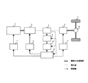
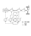
第1の実施形態に用いるハイブリット車両の概略図を図1に示す。ここではシリーズハイブリット車両を用いる。本実施形態では、セルコントローラ9において各セル電圧が所定範囲内であるかどうかを判断することにより過充放電の可能性を判断し、その結果に基づいて統合コントローラ12において充放電を制御する。なお、ここではセルコントローラ9で過充放電の可能性を判断しているが、この限りではなく、例えば過放電の可能性のみを検出する回路を用いたり、放電制御を行うためのコントローラを個別に備えたりしてもよい。
【0015】
パワートレインは、エンジン1と、エンジン1に直結されエンジン1の出力を電力に変換したり、始動時にクランキングを行ったりする発電機2、発電機2で生成された電力の貯蔵部である蓄電装置3を備える。さらに、発電機2で発生した電力、または、蓄電装置3に蓄えられた電力、または、それら両方の電力で駆動される駆動モータ4を備える。駆動モータ4のトルクはファイナルギア6を介してタイヤ5に伝達され、車両の駆動力として使用される。
【0016】
制御系としては、ハイブリット車両を統合的に制御する統合コントローラ12、統合コントローラ12から出力されるエンジン1のトルク指令値を実現するようにスロットル開度を制御するエンジンコントローラ7を備える。また、発電機2の回転速度が、統合コントローラ12から出力される回転速度指令値と等しくなるように発電機2をベクトル制御する発電機コントローラ8を備える。さらに、統合コントローラ12から出力されるモータトルク指令値に基づき駆動モータ4のトルクをベクトル制御する駆動モータコントローラ11を備える。
【0017】
また、蓄電装置3の制御系として、セルコントローラ9と蓄電装置コントローラ10を備える。セルコントローラ9は複数の電池で構成された蓄電装置3の各セルの電圧のバラツキを抑制したり、過充放電の可能性があるかどうかを判断したりする回路を備える。各セルの状態の情報は統合コントローラ12に送られる。蓄電装置コントローラ10は、蓄電装置3全体の電圧・電流を検出し、蓄電装置3への入出力可能な電力を演算して統合コントローラ12に送る。
【0018】
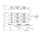
図2にセルコントローラ9の回路構成を示す。図2(a)に概要を、(b)に詳細な回路を示す。
【0019】
蓄電装置3を構成する直列に接続された複数の電池セル1n(n=1、2、3・・・)各々に、セル間の電圧のバラツキを抑えるための電流バイパス2n(n=1、2、3・・・)を備える。また、電池セル1nの過充電が生じる可能性を検出するための過充電検出回路3n(n=1、2、3・・・)と、電池セル1nの過放電が生じる可能性を検出するための過放電検出回路4n(n=1、2、3・・・)を備える。さらに、各セル毎の過充電検出回路3nおよび過放電検出回路4nの検出結果を出力するセル出力部5n(n=1、2、3・・・)と、蓄電装置3の過充電または過放電の可能性があるかどうかを出力する出力部6を備える。
【0020】
出力部6からの出力は統合コントローラ12に送られる。ここでは、いずれかの電池セル1nで過充電もしくは過放電の少なくとも一方が生じる可能性がある場合には1、それ以外には0という信号を統合コントローラ12に送る。
【0021】
図2(b)に示すように、セル電圧のバラツキを抑制する電流バイパス流路2nには、電池と並列に内部抵抗とツェナーダイオード(例えば、逆方向電圧が3.8V)を備える。ここでは、セル電圧が逆方向電圧を超えた場合に内部抵抗に電流が流れる。このため、充電を継続すると、電池セル1nの電圧が逆電圧近傍にそろい、各電池セル1nの電圧のバラツキを抑制することができる。
【0022】
過充電検出回路3nには電圧コンバータを備え、各電池セル1nでの電圧が第2の比較電圧より大きくなったらセル出力部5nに信号(例えば、1)を出力する。ここで、第2の比較電圧は、電池セル1nが過充電となる可能性があり、充電電力の制限を開始する充電制限開始電圧とする。このときp型MOSトランジスタを導通させるかどうかにより第2の比較電圧を切り替える。p型MOSトランジスタを導通させた場合には第2の比較電圧が低くなり(例えば、第2の比較電圧が3.9[V])、導通させない場合には第2の比較電圧が高くなる(例えば、第2の比較電圧が4.1[V])。このp型MOSトランジスタを導通させるかどうかについては走行状態に応じて統合コントローラ12において判断する。その判断に反映した信号がセルコントローラ9に送られて、p型MOSトランジスタを導通させる。
【0023】
過放電検出回路4nには電圧コンバータを備え、各電池セル1nの電圧が第1の比較電圧より小さくなったらセル出力部5nに信号(例えば、1)を出力する。ここで、第1の比較電圧は、電池セル1nが過放電となる可能性があり、放電電力の制限を開始する放電制限開始電圧とする。このときn型MOSトランジスタを導通させるかどうかにより第1の比較電圧を切り替える。n型MOSトランジスタを導通させた場合には第1の比較電圧が低くなり(例えば、第1の比較電圧が2[V])、導通させない場合には第1の比較電圧が高くなる(例えば、第1の比較電圧が2.3[V])。また、n型MOSトランジスタを導通させるかどうかについては、走行状態に応じて統合コントローラ12により判断し、その判断を反映した信号がセルコントローラ9に送られる。
【0024】
なお、本発明の過放電検出回路4nでは、エンジン1の始動時以外の場合には第1の比較電圧を高い状態に、エンジン1の始動時には第1の比較電圧を低い状態に設定する。電圧セル1nの電圧のいずれかがこのような第1の比較電圧より低くなった場合に、過放電検出回路4nの出力信号を1としてセル出力部5nに出力し、放電電力の制限を開始する。
【0025】
ここで、図2のセルコントローラ9では、n型およびp型MOSトランジスタを導通させるか否かを切り替える統合コントローラ12からの信号が共通である。そのため、図3に示すように、p型MOSトランジスタが導通状態であればn型MOSトランジスタが導通状態ではないし、p型MOSトランジスタが導通状態でなければn型MOSトランジスタが導通状態となる関係がある。つまり、第1の比較電圧を低く設定した場合には第2の比較電圧の値は高く設定され、放電および充電の制限を生じにくくする。なお、放電側、充電側で別々の制限を設けたい場合には、図2に示す構成ではなく、nおよびp型MOSトランジスタの導通状態を切り替える信号を別々に設ければよい。
【0026】
また、各電池セル1nからの出力信号がセル出力部5nからの一本のみであるので、過充電回路3nの出力信号が1であるのか、過放電検出回路4nの出力信号が1であるのかを判断することができない。このため、蓄電装置コントローラ10において検出した蓄電装置3の電圧に基づいて、満充電付近の電圧であるならば過充電検出回路3nからの出力が1、逆に低い電圧であるならば過放電検出回路4nからの出力が1であると推定する。この推定結果により、過放電と過充電のどちらが生じる可能性があるのかを判断する。ここで他の状態として、あるセル1aの過充電回路3aの出力信号が1、その他のあるセル1bの過放電回路4bの出力信号が1でありセルコントローラ9からの出力部6が1となる場合が考えられる。つまり、過充電と過放電の可能性が同時に発生している場合であるが、図2に示すように各セル間の電圧のバラツキを抑制するバイパス回路2nを備えるため、このような状態が発生する可能性は極めて低いと考えることができる。
【0027】
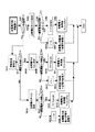
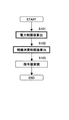
次に、本実施形態の放電の制御方法を図4のフローチャートを用いて説明する。ここでは、過放電が生じる可能性があると判断して放電制限を開始する電圧を前述の第1の比較電圧の値とする。エンジン1の始動時には低い第1の比較電圧を放電制限の開始電圧とし、それ以外の場合には高い第1の比較電圧を放電制限の開始電圧とする。本処理は、一定周期、例えば100[msec]毎に繰り返す。
【0028】
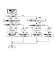
ステップS401において、蓄電装置3から取り出す放電電力の制限値Pd_lmt[kW]を求める。これは、図5の放電電力制限値算出のフローチャートに従って求めることができる。
【0029】
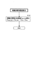
ステップS501において、エンジン1が始動中であるかどうかを判断する。
この判断は、統合コントローラ12からのエンジン始動指令値を基に判断することができる。エンジン1が始動中であると判断されたらステップS502に進み、過放電検出回路4nの比較電圧切り替えスイッチをONにする。この比較電圧切り替えスイッチは、図2の各セルに備えた過放電検出回路4nのn型MOSトランジスタであり、ONにすることによりこれを導通させる。これにより、過放電の生じる可能性を検出する基準値となる第1の比較電圧を低い値に設定する。
その結果、セル電圧が低い値となるまで放電電力の制限は開始されず、蓄電装置3の蓄電量が少ない場合でも、一時的に多くの電力を取り出すことができる。なお、この比較電圧切り替えスイッチの切り替えは、統合コントローラ12からの信号に基づいて行われる。
【0030】
ステップS503において、過放電検出回路4nの出力信号が1であるセルがあるかどうかを判断する。つまり、電池セル1nのうち過放電となる可能性があるものがあるかどうかを判断する。ここでは、前述したように蓄電装置コントローラ10で求めた蓄電装置3の電圧に基づき、出力部6からの信号が過充電の可能性を示すものか過放電の可能性を示すものかを推定する。
【0031】
ステップS503において、過放電の可能性がある電池セル1nが存在すると判断された場合には、ステップS504に進む。ステップS504では、カウントアップタイマー値t[sec]に演算周期t_sample[sec]を加える。ここで、カウントアップタイマー値t[sec]は過放電の可能性があると判断された継続時間を示す。つまり、放電電力の制限が継続している時間を示す。初期値は0である。
【0032】
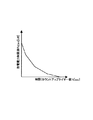
次に、ステップS505において、カウントアップタイマー値t[sec]に基づいて、放電電力制限値Pd_lmt[kW]を算出する。具体的には、図16に示すテーブルからカウントアップタイマー値tに対応する放電電力制限値Pd_lmtの値を読み出す。このテーブルは、予め実験等を行って設定されるものであり、過放電とならない範囲で蓄電装置3から取り出すことが可能な電力の上限に近い値となっている。取り出し可能な電力は、放電時間の経過とともに小さくなるので、放電電力制限値Pd_lmtの値も、カウントアップタイマー値tが増すごとに小さくなるよう設定されており、最終的には放電禁止(Pd_lmt=0[kW])となる。このような方法で放電電力制限値Pd_lmtを算出することにより、放電制限の開始から放電禁止に至るまでの間、放電電力の制限量が徐々に変化することになり、駆動モータ4へ供給される電力の急変が抑制され、ドライバに違和感を与えることがない。
【0033】
一方、ステップS503において過放電検出回路4nの出力が1でない、つまり、全ての電池セル1nの電圧が第1の比較電圧より高いと判断されたら、ステップS506に進む。このときには過放電の可能性がないと判断して、ステップS506において、カウントアップタイマー値t[sec]をリセットする。次に、ステップS507において、放電電力制限値Pd_lmt[kW]を設定する。ここでは例えば放電電力制限値Pd_lmt[kW]として、蓄電装置3の放電可能電力を設定する。放電可能電力は、蓄電装置3から取り出すことのできる電力値である。放電可能電力は以下の式(1)から算出することができる。
【0034】
【式1】
(放電可能電力)= 最低電圧×(開放電圧−最低電圧)/内部抵抗…(1)
開放電圧は、蓄電装置3の充電状態(SOC)との関係を予め実験で求め、図17に示すようなテーブルとして記憶しておくことで求めることができる。また、内部抵抗についても同様に、図18に示すようなテーブルを用いて求めることができる。最低電圧は、バッテリの使用可能電圧やインバータなどの車両からの制約から決まり、ここでは例えば200[V]とする。
【0035】
一方、ステップS501において、エンジン1が始動中でないと判断された場合には、ステップS508に進む。ステップS508において、比較電圧切り替えスイッチをOFFにして、第1の比較電圧を高い値に設定する。これにより、各セルの電圧値が比較的に高い時点から、放電電力の制限を行う。
【0036】
ステップS509に進み、過放電検出回路4nのコンパレータの出力信号が1であるかどうかを判断する。ここで出力が1の場合には、いずれかのセル電圧値が第1の比較電圧より低くなっている状態である。この場合には、ステップS510に進み、カウントアップタイマー値t[sec]を、演算周期t_sample[sec]を加えた値とする。ステップS511において、カウントアップタイマー値t[sec]に応じて放電電力制限値Pd_lmt[kW]を算出する。ここでは、ステップS505における処理と同様に、図16に示すテーブルを使って放電電力制限値Pd_lmtを算出する。
【0037】
一方、ステップS509において、過放電検出回路4nの出力信号が1ではないと判断された場合には、放電制限を行う必要のないセル電圧状態にある。そのため、ステップS512に進み、カウントアップタイマー値t[sec]の値をリセットし、ステップS513において、放電電力制限値Pd_lmt[kW]として放電可能電力を設定する。これは、上記式(1)から求めることができる。
【0038】
以上のように、エンジン1の始動時以外の場合には第1の比較電圧を高い状態に設定し、エンジン1の始動時には第1の比較電圧を低い状態に設定する。いずれか一つの過放電検出回路4nの出力信号が1となった場合、つまりいずれかのセル電圧の値が第1の比較電圧より低くなった場合に、放電電力の制限を開始する。このため、従来ではエンジン1の始動時であってもそれ以外の場合と同様に放電電力を制限していたものに対して、エンジン1の始動時においてはより多くの電力を始動に用いることができる。これにより、バッテリ残量が少ない場合でもエンジン1の始動に失敗する可能性が低く、つまりは、エンジン1を始動できる頻度が高くなる。
【0039】
このようにステップS401において、運転状況に応じて放電電力制限値Pd_lmt[kW]を設定したら、ステップS402において、エンジン1の始動のために電力が使われるように、その他駆動モータおよび補機類で消費する電力を制限する。これは、図6の駆動モータ/補機消費制限値算出に関するフローチャートに従って制御する。
【0040】
ステップS601において、駆動モータ4で消費できる電力の制限値Pdrv_lmt[kW](≧ 0)を次式(2)から求める。
【0041】
【式2】
Pdrv_lmt = Pd_lmt −Pstr −Paux_min−Pmrg …(2)
ここで、Pstr[kW]はエンジン1の始動時に発電機2を用いてクランキングする際に消費する電力、Paux_min[kW]はパワーステアリングなどに走行に最低限必要な補機類の消費電力、Pmrg[kW]はマージン分の電力(例えば、2[kW])である。駆動モータ4の消費電力を制限値Pdrv_lmtで制限することにより、エンジン始動1に必要な電力を確実に確保する。ただし、エンジン始動時以外にはPstr=0[kW]とする。なお、駆動モータ4の消費電力の制限は、駆動モータ4に対する指令トルクを制限することによって実現することができる。
【0042】
ステップS602において、駆動モータ4の消費電力制限値Pdrv_lmt[kW]と、駆動モータ消費電力Pdrv[kW]の大小を比較する。ここで、駆動モータ消費電力Pdrv[kW]は次式(3)から求められる。
【0043】
【式3】
Pdrv =( VSP*Tm*Gtotal)/(60*60*R) …(3)
ここで、VSP[km/h]は車両走行速度、Tm[Nm]はドライバが要求する運転を実現するためのモータトルク、Gtotalは総減速比、R[m]はタイヤの有効半径を示す。
【0044】
ステップS602において、駆動モータ消費電力制限値Pdrv_lmt[kW]が駆動モータ消費電力Pdrv[kW]よりも大きいと判断された場合には、ステップS603に進む。ステップS603において補機消費電力制限値Paux_lmt[kW]を次式(4)から求める。
【0045】
【式4】
Paux_lmt = Pdrv_lmt ― Pdrv …(4)
ここで求めた補機消費電力制限値Paux_lmt[kW]は、エアコンなど直接走行に影響することがない補機類の動作に用いることができる電力値である。補機類の消費電力を制限値Paux_lmtで制限することにより、ドライバが要求する運転を実現するための電力が確保される。
【0046】
一方、ステップS602において、駆動モータ消費電力制限値Pdrv_lmt[kW]が駆動モータ消費電力Pdrv[kW]より小さいと判断された場合には、補機類に用いる電力はないと判断する。そこで、ステップS604においてエアコン等の動作を停止する。
【0047】
このように、補機類に用いることのできる電力を制限して、駆動モータ4において用いる電力を可能な限り確保する。これにより、より多くの電力を駆動に用いることができ、要求される運転を行うことができる頻度を増大することができる。
【0048】
次に、ステップS403において、放電電力の制限値を超えないように求めたエンジン1、発電機2、駆動モータ4への指令値を実現する。
【0049】
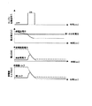
エンジン1の始動時に、このように制御した場合の電池電圧、電力、発電機トルクを図8に示す。また、比較例として従来の制御方法を用いた場合のエンジン1の始動時の電池電圧、電力、発電機トルクを図7に示す。
【0050】
従来に比べて本実施形態では、エンジン1の始動時には放電制限開始電圧(第1の比較電圧)が低くなるので、蓄電量が小さい場合にも放電制限を行わない状態で電力を取り出すことができる頻度が高くなる。これにより、従来の方法ではエンジン1の始動時に取り出す電力が制限され、発電機2のトルクも抑制されたが、本実施形態では、必要な電力を取り出して発電機2のトルクを生じることができる。これにより、エンジン1が始動される頻度が高くなる。
【0051】
次に、本実施形態の効果を説明する。
【0052】
エンジン1と発電機2を備えた発電装置と、電池を備えた蓄電装置3と、駆動モータ4と、を備えたハイブリット車両の電池制御装置において、蓄電装置3を構成する電池の電圧が第1の比較電圧未満か否かを判断する第1の判断手段(S503、S509)を備える。また、第1の判断手段により電圧が第1の比較電圧未満であると判断された場合には、蓄電装置3からの放電を制限する放電電力制限手段(S505、S511)と、エンジン1が蓄電装置3からの電力を受ける発電機2により始動中であるかどうかを検知するエンジン始動検出手段(S501)と、を備える。エンジン1が始動中である場合には、放電電力制限手段による放電の制限を抑制する。これにより、エンジン1の始動中に蓄電装置3の蓄電量が小さい場合にも、その電力をエンジン1の始動に用いることができるため、エンジン1が始動する頻度が高くなる。
【0053】
エンジン1が始動中である場合には、第1の比較電圧の値を低く設定することにより放電の制限を抑制する。これにより、電池セル電圧が第1の比較電圧より小さくなる頻度を抑えることができるので、放電制限が行われ難くなる。つまり、発電機2を用いてクランキングする際に用いる電力が制限される頻度が小さくなるため、エンジン1を始動できる頻度が高くなる。
【0054】
また、エンジン1の始動中には、駆動モータ4に用いる電力を制限する。これにより、エンジン1の始動のために確保した電力が、エンジン1の始動ではなく駆動モータ4で消費されるのを抑制することができる。その結果、エンジン1の始動に用いる電力を増加でき、エンジン1を始動できる頻度を高くすることができる。
【0055】
また、エンジン1の始動中には、エンジン1の始動に関与しない車両の補機類に用いる電力を制限する。これにより、エンジン1の始動のために確保した電力が、エンジン1の始動ではなく補機類で消費されるのを抑制することができる。
その結果、エンジン1の始動に用いる電力を増加でき、エンジン1を始動できる頻度を高くすることができる。
【0056】
また、エンジン1が始動中である場合には、放電電力の制限量を小さくする。
本実施形態で示した制御を行うことで、第1の比較電圧が高い場合に比べて第1の比較電圧が低い場合には、あるセル電圧に対する放電電力制限値Pd_lmt[kW]が高くなる。つまり、あるセル電圧に対する放電電力の制限量が小さくなる。これは、第1の比較電圧を低く設定した場合には、高く設定した場合に比べて遅れて放電制限が開始されるので、同じセル電圧に達した時点でのカウントアップタイマー値t[sec]の値が小さくなるためである。
【0057】
つまり、本実施形態では、エンジン始動中の放電制限開始タイミングを通常時のタイミングより遅らせることで始動用の電力を増大させるだけでなく、エンジン始動中の放電制限量を通常時の制限量より小さくすることによっても始動用の電力を増大させるようにしている。
【0058】
なお、エンジン1の始動時に放電電力制限値Pd_lmt[kW]を高く設定して放電制限量を小さくすることだけで放電制限を抑制してもよい。つまり、エンジン1の始動時に、放電電力制限値Pd_lmt[kW]を通常より高く設定することで、蓄電装置3から取り出せる電力を増加することができる。このときは、比較的高い放電電力制限値Pd_lmt[kW]を設定した第1のテーブルと比較的低い放電電力制限値Pd_lmt[kW]を設定した第2のテーブルとを用意しておき、図5の放電電力制限値算出のフローにおいては、ステップS502で第1の比較電圧を低い値に設定する替わりに、ステップS505で第1のテーブルから放電電力制限値Pd_lmtを算出する。また、ステップS508で第1の比較電圧を高い値に設定する替わりに、ステップS511で第2のテーブルから放電電力制限値Pd_lmtを算出する。これにより、エンジン1の始動時に取り出す電力を増加することができる。
【0059】
次に、第2の実施形態について説明する。第1の実施形態の構成と同様とし、以下、制御方法の異なる部分のみを説明する。
【0060】
ここでは、第1の実施形態に加えて、エンジン1の始動時以外の場合でも、雰囲気温度に応じて放電制限を開始する電圧の切り替えを行う。ここで、エンジン1の始動時に雰囲気温度が低い場合、つまりエンジン1冷機時にはエンジンオイルの粘度が高くなりフリクションが大きくなる。そこで、このフリクションにうちかってエンジン回転数を上げるための発電機2の出力が要求される。また、気化燃料の減少による着火や完爆がしにくいため、長期間発電機2を回転させるためのエネルギが要求される。
【0061】
そこで、雰囲気温度からエンジンオイルの温度を推定し、エンジンオイル温度に応じて放電制限を開始する電圧を設定する。ここでは、図19のように、常温(0〜25[℃])の場合に放電制限を開始する電圧Vaに対して、雰囲気温度が低い場合、ここでは0℃より低い場合には放電制限を開始する電圧Vbを高く設定する。本実施形態においては、この高い電圧値Vbを、図2の回路における放電検出回路2nの比較電圧切り替えスイッチをOFFにした際の第1の比較電圧の値(例えば、2.3[V])とする。一方、常温時の放電制限を開始する電圧値Vaを比較電圧切り替えスイッチをONにした際の比較電圧の値(例えば2.0[V])とする。なお、ここでは図2に示す回路構成上、放電制限開始電圧(第1の比較電圧)を2段階としたが、第1の比較電圧を連続的に変更できるような回路を用いれば、より雰囲気温度に見合った放電制限開始電圧を設定することができる。
【0062】
次に、上記のような制御を行うためのフローを説明する。全体の流れには、第1の実施形態と同様に図4のフローチャートを用いる。ステップS401における放電電力制限値算出のフローを図9に示す。
【0063】
ステップS901において、エンジン1が始動中と判断されたら、ステップS902に進み、第1の比較電圧を低い値Vaに設定する。本実施形態では、比較電圧切り替えスイッチをONにする。以下第1の実施形態と同様の制御を行う。一方、ステップS901でエンジン1が始動中と判断されなかったら、ステップS914に進み、雰囲気温度を検出する。次に、ステップS915において、検出した雰囲気温度が所定の温度(ここでは0℃)未満かどうかを判断する。
【0064】
雰囲気温度が0℃以上の場合には、エンジン1の始動時に必要な電力が少なくてよいと判断して、ステップS916に進み、図19に示す放電制限を開始する電圧Vcを低い電圧に設定する。ここでは比較電圧切り替えスイッチをONにすることで第1の比較電圧の切り替えを行うので、エンジン1の始動時と同様の電圧Vaに設定される。その後、第1の実施形態と同様に放電電力制限値Pd_lmt[kW]を求める。一方、雰囲気温度が0℃未満の場合には、エンジン1の始動時に大きな電力が必要となると予測してステップS908に進む。ここでは、蓄電装置3の蓄電量を確保するために、図19に示すように放電制限を開始する電圧Vbを高い値に設定する(比較電圧切り替えスイッチOFF)。その後、第1の実施形態と同様に放電電力制限値Pd_lmt[kW]を求める。
【0065】
なお、ここでは第1の比較電圧を二段階として、エンジン1の始動中の放電制限開始電圧Vaと、雰囲気温度が高い通常時の放電制限開始電圧Vcと、を同じにしたが、第1の比較電圧を三段階として、それぞれに応じた電圧に設定することもできる。このときは、Va<Vc<Vbと設定することができる。また、前述した様に、第1の比較電圧を連続的に変化可能として、雰囲気温度が低いほど放電制限開始電圧を高く設定してもよい。また、ここでは、放電制限開始電圧の切り替えを雰囲気温度に応じて行っているが、エンジンオイルや冷却水の温度に応じて行ってもよい。
【0066】
次に、本実施形態の効果を説明する。ここでは、第1の実施形態における効果に加えて以下のような効果を得ることができる。
【0067】
雰囲気温度が高い通常運転時は、蓄電装置27の電力をぎりぎりまで利用可能にして車両の運転性を確保する。雰囲気温度が高いときは、エンジン1の始動に必要な電力量が少ないので、雰囲気温度が高いときに蓄電装置27の残量が少なくなってもあまり問題がない。一方、雰囲気温度が低いときは、エンジン1の始動に多くの電力が必要となることが予想されるので、通常運転時の電力制限を早めに開始し、蓄電装置27の残量を高めに維持する。これにより、雰囲気温度が低いときにエンジン1を始動することになっても始動に失敗する可能性が低くなる。
【0068】
次に、第3の実施形態について説明する。ここでは、パラレルハイブリット車両を用い、その構成を図10に示す。
【0069】
パワートレインは、エンジン21を備える。また、エンジン21に直結され、エンジン21の出力の一部を電力に変換したり、後述する蓄電装置27に蓄えられている電力を用いて駆動トルクを発生してエンジン21で発生したトルクアシストを行うモータ22を備える。さらに、モータ22の出力軸と締結された有段自動変速機23(以下、変速機23)と減速装置24を備え、エンジン21およびモータ22で発生したトルクはファイナルギア26を介してタイヤ25に伝達される。また、モータ22には蓄電装置27が連結され、モータ22に電力を供給する。
【0070】
制御系としては、第1の実施形態と同様に、全体を制御する統合コントローラ33、エンジン21を制御するエンジンコントローラ29、蓄電装置29の制御系であるセルコントローラ28と蓄電装置コントローラ31を備える。また、統合コントローラ33から出力されるモータトルク指令値に基づきモータ22のトルクをベクトル制御するモータコントローラ30を備える。さらに、変速機コントローラ32を備え、統合コントローラ33においてドライバのアクセル操作と車両速度に応じて、ドライバの駆動力要求に見合うように算出された変速段を実現するように変速機23を制御する。
【0071】
また、統合コントローラ33においては、変速時にエンジン21とモータ22および変速機23を用いたトルク協調制御を行う。これは、変速中に発生する変速ショックを抑制するようにエンジン21とモータ22で発生するトルクを制御し、スムーズな変速を実現するものである。
【0072】
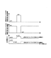
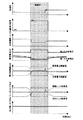
図11に従来の変速中に行われるトルク協調制御時の各トルクおよび電力の状態を示す。例えば、変速比を低下させるアップシフトの場合には、入力回転数を返送後の変速比における同期回転数まで低下させる必要があり、また変速比を増大させるダウンシフトの場合には、入力回転数を変速後の変速比における同期回転数にまで増大させる必要がある。このような入力回転数の変化に伴う感性トルクが出力軸トルクに現れ、これが変速ショックとなることがある。そこでトルク協調制御、ここでは、モータ22に供給する電力を調整することで、この変速ショックを抑制する。
【0073】
図11に示すように、トルク協調制御を行う場合にはモータ22に電力を供給、またはモータ22から電力を回収することになる。しかしながら、電池電圧(蓄電量)が小さい場合には放電の制限が行われる可能性があり、十分に駆動トルクを発生できない場合がある。また、電池電圧(蓄電量)が大きい場合には充電の制限が行われている可能性があり、十分に回生トルクを発生できないという場合がある。
【0074】
そこで本実施形態では図12に示すように、変速中には放電制限を開始する電圧値(第1の比較電圧)を低い値に設定することで放電制限を抑制し、変速ショックを抑制するための駆動トルクを生じるのに必要な放電電力を確保する。また同じく変速中には、充電制限を開始する電圧値(第2の比較電圧)を高い値に設定することで充電制限を抑制し、変速ショックを抑制するための回生トルクを生じるのに必要な充電電力を確保する。
【0075】
セルコントローラ28には、第1の実施形態と同様に図2の回路構成を用いる。図2で説明したように、nおよびp型MOSトランジスタを導通させるかどうかを切り替える信号が共通であるため、図3に示すような各MOSトランジスタの導通状態と比較電圧との関係がある。ここでは、変速中に充電および放電の両方の制限を抑制するので、図3に示すように共通の信号で制御することができる。統合コントローラ33では、この比較電圧を用いた比較結果を受けて充電および放電の制限値を求める。
【0076】
次に、本実施形態の制御方法を図13〜図15のフローチャートを用いて説明する。この処理は、一定周期、例えば100[msec]毎に実行する。
【0077】
ステップS101において、各セルの電圧に基づいて蓄電装置27からの放電電力および充電電力の制限値を求める。この電力制限値算出のフローを図14に示す。
【0078】
ここでは、第1の実施形態に用いた放電電力制限値算出のフロー(図5)におけるステップS501のエンジン始動中の判断の替わりに、ステップS111において、変速中であるかどうかの判断を行う。変速中であればステップS112に進み、比較電圧切り替えスイッチをONとして第1の比較電圧を低い値に、第2の比較電圧を高い値に設定する。これにより、セル電圧が低い電圧値になるまで放電制限が行われないとともに、セル電圧が高い電圧値になるまで充電制限が行われない。一方、ステップS111において変速中でないと判断されたら、比較電圧切り替えスイッチをOFFにして、比較的はやい段階から徐々に充放電の制限を行う。
【0079】
また、第1の実施形態と同様にステップS115、S123において、放電電力制限値Pd_lmt[kW]を求めたら(図5のS505、S511に相当)、続いてステップS116、S124において充電電力の制限値Pc_lmt[kW]を求める。
これは、カウントアップタイマー値t[sec]に基づいて図21に示すマップを検索することにより求めることができる。このマップは、過充電を防ぐためにカウントアップタイマー値t[sec]が増加するほど充電電力制限値が小さくなるように、予め実験等により設定しておく。
【0080】
さらに、第1の実施形態と同様にステップS118、S126において、放電電力制限値Pd_lmt[kW]として放電可能電力を求めたら(図5のS507、S513に相当)、続いてステップS119、S127において、充電電力の制限値Pc_lmt[kW]として充電可能電力を求める。充電可能電力は(5)式より求めることができる。
【0081】
【式5】
(充電可能電力)=最高電圧×(最高電圧―開放電圧)/内部抵抗 ・・・(5)
開放電圧は蓄電装置27の充電状態(SOC)との関係を予め実験等で求め、求めた値を図17に示すようなテーブルとして記憶することで求めることができる。
また、内部抵抗についても同様に、図18に示すようなテーブルを用いて求めることができる。最高電圧は、蓄電装置27の電圧使用範囲の制約から決まり、ここでは例えば400[V]とする。
【0082】
このように充電電力および放電電力の制限開始電圧を設定したら、ステップS102において、放電電圧を用いてモータ22の変速時のトルク協調制御を行えるように、その他の補機類で消費される電力を制限する。この制御方法を図15に示した補機消費制限値算出のフローを用いて説明する。
【0083】
ステップS131において、補記消費電力制限値Paux_lmt[kW](≧0)は次式(6)から求めることができる。
【0084】
【式6】
Paux_lmt=Pd_lmt−Pdrv−Ptrs ・・・(6)
ここで、Ptrs[kW]はトルク協調制御に用いる電力であり、予め実験等により求めることができる。また、Pdrv[kW]は、モータ22において駆動に消費される電力であり、式(7)から求めることができる。
【0085】
【式7】
Pdrv=(VSP*Tm*G*Gf)/(60*60*R) ・・・(7)
ここで、VSP[km/h]は車両走行速度、Tm[Nm]はモータトルク、Gは有段自動変速機の変速以前の変速比、Gfは変速機23の変速比、R[m]はタイヤの有効半径を示す。
【0086】
このように補機類の消費電力の制限を行ったら、ステップS103に進み、制限値を超えないように求めたエンジン21、モータ22、変速機23への指令値を実現する。
【0087】
次に、本実施形態の効果を説明する。
【0088】
エンジン21と、モータ22と、蓄電装置27と、変速機23とを備え、エンジン21とモータ22の少なくとも一方の動力を、変速機23を介して出力軸に伝達するハイブリット車両の電池制御装置を次のように構成する。蓄電装置27を構成する電池の電圧が第1の比較電圧未満か否かを判断する第1の判断手段(S113、S121)を備える。また、第1の判断手段において、電池の電圧が第1の比較電圧未満であると判断された場合には、蓄電装置27からの放電電力を制限する放電電力制限手段(S115,S123)を備える。さらに、変速時に生じる変速ショックを打ち消すように、エンジン1とモータ22で発生するトルクを制御するトルク協調制御が動作中であるかどうかを検知するトルク協調制御動作検出手段(S111)と、を備える。このような電池制御装置において、トルク協調制御が動作中である場合には、放電電力制限手段による放電制限を抑制する。これにより、変速ショックを抑制するためにモータ22に駆動トルクを生じさせるために必要な電力が制限されるのを抑制できる。
【0089】
ここでは第1の比較電圧の値を低く設定する。これにより、放電制限が生じ難くなるので、変速ショックを抑制するための電力が制限される頻度を低減することができ、変速ショックに伴ってドライバに違和感を与える頻度を低減できる。
【0090】
また、蓄電装置27を構成する電池の電圧が第2の比較電圧より高いか否かを判断する第2の判断手段(S113、S121)と、第2の判断手段において、電池の電圧が第2の比較電圧より高いと判断された場合には、蓄電装置27からの充電電力を制限する充電電力制限手段(S116、S124)と、を備える。
また、変速時に生じる変速ショックを打ち消すように、エンジン21とモータ22で発生するトルクを制御するトルク協調制御が動作中であるかどうかを検知するトルク協調制御動作検出手段(S111)と、を備える。トルク協調制御が作動中である場合には、充電電力制限手段による充電制限を抑制する。これにより、変速ショックを抑制するためにモータ22に回生トルクを生じさせるのに必要な充電電力が制限されるのを抑制することができる。
【0091】
ここでは第2の比較電圧の値を高く設定する。これにより充電制限が生じ難くなるので、変速ショックを抑制するための電力が制限される頻度を低減することができ、変速ショックに伴ってドライバに違和感を与える頻度を低減できる。
【0092】
なお、ここでは変速時にはトルク協調制御を行うので変速中であるかどうかを判断することで、トルク協調制御中であることを判断しているが、トルク協調制御の信号が出力されているかどうかで判断してもよい。また、本実施形態も第1の実施形態と同様に、放電の制限量を低減することで、放電制限を抑制することができる。また、充電制限量を低減することで、充電制限を抑制することができる。さらに、変速中には、エンジン21の始動に関与しない車両の補機類に用いる電力を制限することで、変速ショックを抑制するための電力を確保することができる。
【0093】
このように、本発明は上記実施の形態に限定されるわけではなく、特許請求の範囲に記載の技術思想の範囲以内で様々な変更が成し得ることは言うまでもない。
【図面の簡単な説明】
【図1】第1の実施形態に用いるハイブリット車両の概略図である。
【図2】第1の実施形態に用いるセルコントローラの構成図である。
【図3】第1の実施形態に用いるトランジスタの導通状態と比較電圧の関係図である。
【図4】第1の実施形態に用いる制御フローである。
【図5】第1の実施形態における放電電力制限値算出の制御フローである。
【図6】第1の実施形態における駆動モータ/補機類の消費制限値算出のフローである。
【図7】従来の制御方法による電池電圧・電力・発電機トルクの変化を示す図である。
【図8】第1の実施形態における電池電圧・電力・発電機トルクの変化を示す図である。
【図9】第2の実施形態における放電電力制限値算出の制御フローである。
【図10】第3の実施形態に用いるハイブリット車両の概略図である。
【図11】従来の制御方法による出力軸トルク等の変化を示す図である。
【図12】第3の実施形態における出力軸トルク等の変化を示す図である。
【図13】第3の実施形態に用いる制御フローである。
【図14】第3の実施形態における放電電力制限値算出の制御フローである。
【図15】第3の実施形態における補機類の消費制限値算出のフローである。
【図16】タイムアップカウンター値に対する放電電力制限値を示す図である。
【図17】SOCと開放電圧との関係を示す図である。
【図18】SOCと内部抵抗との関係を示す図である。
【図19】雰囲気温度と放電制限開始電圧との関係を示す図である。
【図20】タイムアップカウンター値に対する充電電力制限値を示す図である。
【符号の説明】
1 エンジン
2 発電機
3 蓄電装置
4 駆動モータ
9 セルコントローラ
12 統合コントローラ
21 エンジン
22 モータ
23 変速機
28 セルコントローラ
33 統合コントローラ
4n 過放電検出回路
S503,509,113,121 ・・・ 第1の判断手段
S505,511,115,123 ・・・ 放電電力制限手段
S501 ・・・ エンジン始動検出手段
S111 ・・・ トルク協調制御動作検出手段
S113,121 ・・・ 第2の判断手段
S116,124 ・・・ 充電電力制限手段[0001]
[Industrial applications]
The present invention relates to a battery control device for a hybrid vehicle, and more particularly to a battery charge / discharge limit control.
[0002]
[Prior art]
A battery mounted on a hybrid vehicle needs to generate a high voltage, and a battery using an assembled battery in which many battery cells are connected in series is known. In such an assembled battery, control is performed to detect the voltage of each battery cell, disconnect the battery from the motor if any of the voltages becomes zero, and prohibit further discharge. In this case, the current supplied to the drive motor is cut off when the cell voltage becomes 0, so that the driving performance changes greatly and the driver feels a sense of discomfort.
[0003]
Therefore, in the conventional charge / discharge control device, the discharge current is limited in two stages, discharge limitation and discharge inhibition, to reduce a sense of discomfort given to the driver. Specifically, the battery cell voltage at which the discharge limitation is started is set to a voltage higher than the battery cell voltage at which the discharge is inhibited, and the discharge current value is limited when the battery cell voltage falls below the voltage. In addition, the battery cell voltage at which charging is started is set to a voltage lower than the battery cell voltage at which charging is prohibited, and the charging current value is limited when the battery cell voltage exceeds the voltage. As a result, the change in the driving force of the driving motor becomes gentle, and it is possible to reduce the sense of discomfort given to the driver (for example, see Patent Document 1).
[0004]
[Patent Document 1]
JP-A-11-178225
[0005]
[Problems to be solved by the invention]
However, when the current is limited just before the prohibition of charging / discharging as in the above-described conventional technique, there is a case where the operation is adversely affected depending on the driving situation.
[0006]
For example, when the battery capacity is small when the engine is started, either the vehicle runs with the drive motor using the remaining small battery capacity or the vehicle stops. In such a case, if the discharge power is limited before the discharge is prohibited in order to suppress the uncomfortable feeling given to the driver as in the related art, even though the amount of power capable of starting the engine remains, the discharge power is limited. Therefore, there is a possibility that the vehicle stops.
[0007]
Therefore, an object of the present invention is to provide a battery control device for a hybrid vehicle that can perform charge / discharge control according to a driving situation.
[0008]
[Means for solving the problem]
The present invention relates to a battery control device for a hybrid vehicle including a power generation device including an engine and a generator, a power storage device including a battery, and a drive motor, wherein a voltage of a battery forming the power storage device is the first. A first determining means for determining whether the voltage is lower than a predetermined voltage. Further, when the first determining means determines that the voltage is lower than the first predetermined voltage, the discharge power limiting means for limiting discharge from the power storage device; Engine start detecting means for detecting whether or not the generator receiving electric power is starting. When the engine is being started, the limitation of discharge by the discharge power limiting unit is suppressed.
[0009]
Also, a hybrid vehicle includes an engine, a drive motor, a power storage device, and a stepped transmission, and transmits power of at least one of the engine and the drive motor to an output shaft via the stepped transmission. The battery control device is configured as follows.
First determining means for determining whether or not the voltage of the battery constituting the power storage device is lower than a first predetermined voltage; and determining that the voltage of the battery is lower than the first predetermined voltage. And a discharge power limiting means for limiting the discharge power from the power storage device when the determination is made. Further, there is provided torque cooperative control operation detecting means for detecting whether or not torque cooperative control for controlling torque generated by the engine and the drive motor is in operation so as to cancel a shift shock generated during a shift. In such a battery control device, when the torque coordination control is in operation, the limitation on the discharge by the discharge power limiting unit is suppressed.
[0010]
The hybrid vehicle further includes an engine, a drive motor, a power storage device, and a stepped transmission, and transmits at least one of the power of the engine and the drive motor to an output shaft via the stepped transmission. The battery control device is configured as follows. Second determining means for determining whether the voltage of a battery constituting the power storage device is higher than a second predetermined voltage; and determining whether the battery voltage is higher than a second predetermined value. And charging power limiting means for limiting charging power from the power storage device when the determination is made. Further, there is provided torque cooperative control operation detecting means for detecting whether or not torque cooperative control for controlling torque generated by the engine and the drive motor is in operation so as to cancel a shift shock generated during a shift. In such a battery control device, when the torque cooperative control is in operation, the limitation of charging by the charging power limiting unit is suppressed.
[0011]
[Action and effect]
When the engine is being started, by suppressing the discharge restriction by the discharge power restriction means, it is possible to increase the frequency at which the engine can be started while securing power.
[0012]
Further, when the torque cooperative control is in operation, the frequency at which the discharge power for generating the torque required to suppress the shift shock can be secured by suppressing the discharge limitation by the discharge power limiting means. Can be higher.
[0013]
Further, when the torque coordination control is in operation, by suppressing the charging limitation by the charging power limiting unit, the frequency at which the charging power for generating the torque required to suppress the shift shock can be recovered. Can be higher.
[0014]
BEST MODE FOR CARRYING OUT THE INVENTION
FIG. 1 is a schematic diagram of a hybrid vehicle used in the first embodiment. Here, a series hybrid vehicle is used. In the present embodiment, the possibility of overcharging / discharging is determined by determining whether each cell voltage is within a predetermined range in the cell controller 9, and the integrated
[0015]
The power train includes an engine 1, a generator 2 which is directly connected to the engine 1, converts an output of the engine 1 into electric power, and performs cranking at the time of starting, and a storage unit which is a storage unit of electric power generated by the generator 2. The device 3 is provided. Further, a drive motor 4 driven by the power generated by the generator 2 or the power stored in the power storage device 3 or both powers is provided. The torque of the drive motor 4 is transmitted to the tire 5 via the final gear 6, and is used as a driving force for the vehicle.
[0016]
The control system includes an
[0017]
The power storage device 3 includes a cell controller 9 and a power
[0018]
FIG. 2 shows a circuit configuration of the cell controller 9. FIG. 2A shows an outline, and FIG. 2B shows a detailed circuit.
[0019]
Each of a plurality of series-connected battery cells 1n (n = 1, 2, 3,...) Constituting the power storage device 3 has a current bypass 2n (n = 1, 2, 3) for suppressing a variation in voltage between the cells. , 3 ...). Also, an overcharge detection circuit 3n (n = 1, 2, 3,...) For detecting the possibility of overcharging of the battery cell 1n, and for detecting the possibility of overdischarging of the battery cell 1n. Of overdischarge detection circuits 4n (n = 1, 2, 3,...). Further, a cell output unit 5n (n = 1, 2, 3,...) That outputs detection results of the overcharge detection circuit 3n and the overdischarge detection circuit 4n for each cell, and overcharge or overdischarge of the power storage device 3 And an output unit 6 for outputting whether or not there is a possibility.
[0020]
The output from the output unit 6 is sent to the
[0021]
As shown in FIG. 2B, the current bypass channel 2n for suppressing the variation of the cell voltage includes an internal resistor and a Zener diode (for example, a reverse voltage of 3.8 V) in parallel with the battery. Here, when the cell voltage exceeds the reverse voltage, a current flows through the internal resistance. For this reason, when charging is continued, the voltage of the battery cell 1n becomes close to the reverse voltage, and the variation in the voltage of each battery cell 1n can be suppressed.
[0022]
The overcharge detection circuit 3n includes a voltage converter, and outputs a signal (for example, 1) to the cell output unit 5n when the voltage at each battery cell 1n becomes higher than the second comparison voltage. Here, the second comparison voltage is a charging limit start voltage at which there is a possibility that the battery cell 1n may be overcharged and charging power limit is started. At this time, the second comparison voltage is switched depending on whether the p-type MOS transistor is made conductive. When the p-type MOS transistor is turned on, the second comparison voltage becomes low (for example, the second comparison voltage is 3.9 [V]), and when it is not turned on, the second comparison voltage becomes high ( For example, the second comparison voltage is 4.1 [V]. Whether the p-type MOS transistor is made conductive or not is determined by the
[0023]
The overdischarge detection circuit 4n includes a voltage converter, and outputs a signal (for example, 1) to the cell output unit 5n when the voltage of each battery cell 1n becomes lower than the first comparison voltage. Here, the first comparison voltage is a discharge limit start voltage at which there is a possibility that the battery cell 1n may be overdischarged, and the limitation of the discharge power is started. At this time, the first comparison voltage is switched depending on whether or not the n-type MOS transistor is made conductive. When the n-type MOS transistor is turned on, the first comparison voltage decreases (for example, the first comparison voltage is 2 [V]), and when the n-type MOS transistor is not turned on, the first comparison voltage increases (for example, for example). The first comparison voltage is 2.3 [V]). Whether to make the n-type MOS transistor conductive is determined by the
[0024]
In the overdischarge detection circuit 4n of the present invention, the first comparative voltage is set to a high state when the engine 1 is not started, and the first comparative voltage is set to a low state when the engine 1 is started. When any one of the voltages of the voltage cells 1n becomes lower than the first comparison voltage, the output signal of the overdischarge detection circuit 4n is set to 1 and is output to the cell output unit 5n to start limiting the discharge power. .
[0025]
Here, in the cell controller 9 of FIG. 2, a signal from the integrated
[0026]
Also, since the output signal from each battery cell 1n is only one from the cell output unit 5n, whether the output signal of the overcharge circuit 3n is 1 or the output signal of the overdischarge detection circuit 4n is 1 Can not judge. Therefore, based on the voltage of the power storage device 3 detected by the power
[0027]
Next, the discharge control method of the present embodiment will be described with reference to the flowchart of FIG. Here, it is determined that the overdischarge is likely to occur, and the voltage at which the discharge limit is started is set as the value of the first comparison voltage. When the engine 1 is started, a low first comparison voltage is set as a discharge limit start voltage, and otherwise, a high first comparison voltage is set as a discharge limit start voltage. This process is repeated at regular intervals, for example, every 100 [msec].
[0028]
In step S401, a limit value Pd_lmt [kW] of the discharge power extracted from the power storage device 3 is obtained. This can be determined according to the flowchart of FIG. 5 for calculating the discharge power limit value.
[0029]
In step S501, it is determined whether the engine 1 is being started.
This determination can be made based on an engine start command value from the integrated
As a result, the limitation of the discharge power is not started until the cell voltage becomes a low value, and even when the power storage amount of the power storage device 3 is small, a large amount of power can be temporarily taken out. The comparison voltage switch is switched based on a signal from the integrated
[0030]
In step S503, it is determined whether or not there is a cell whose output signal of the overdischarge detection circuit 4n is 1. That is, it is determined whether or not there is a battery cell 1n that may be over-discharged. Here, as described above, based on the voltage of the power storage device 3 obtained by the power
[0031]
If it is determined in step S503 that there is a battery cell 1n that may be overdischarged, the process proceeds to step S504. In step S504, a calculation cycle t_sample [sec] is added to the count-up timer value t [sec]. Here, the count-up timer value t [sec] indicates a continuation time in which it is determined that there is a possibility of overdischarge. That is, it indicates the time during which the limitation of the discharge power continues. The initial value is 0.
[0032]
Next, in step S505, a discharge power limit value Pd_lmt [kW] is calculated based on the count-up timer value t [sec]. Specifically, the value of the discharge power limit value Pd_lmt corresponding to the count-up timer value t is read from the table shown in FIG. This table is set in advance by performing an experiment or the like, and has a value close to the upper limit of the power that can be extracted from the power storage device 3 within a range that does not cause overdischarge. Since the power that can be taken out decreases as the discharge time elapses, the value of the discharge power limit value Pd_lmt is also set to decrease as the count-up timer value t increases, and finally the discharge prohibition (Pd_lmt = 0 [kW]). By calculating the discharge power limit value Pd_lmt in such a manner, the limit amount of the discharge power gradually changes from the start of the discharge limit to the prohibition of the discharge, and is supplied to the drive motor 4. A sudden change in power is suppressed, and the driver does not feel uncomfortable.
[0033]
On the other hand, if it is determined in step S503 that the output of the overdischarge detection circuit 4n is not 1, that is, that the voltages of all the battery cells 1n are higher than the first comparison voltage, the process proceeds to step S506. At this time, it is determined that there is no possibility of overdischarge, and in step S506, the count-up timer value t [sec] is reset. Next, in step S507, a discharge power limit value Pd_lmt [kW] is set. Here, for example, dischargeable power of power storage device 3 is set as discharge power limit value Pd_lmt [kW]. The dischargeable power is a power value that can be extracted from the power storage device 3. The dischargeable power can be calculated from the following equation (1).
[0034]
(Equation 1)
(Dischargeable power) = minimum voltage x (open voltage-minimum voltage) / internal resistance ... (1)
The open-circuit voltage can be obtained by obtaining the relationship with the state of charge (SOC) of the power storage device 3 in advance by experiment and storing it in a table as shown in FIG. Similarly, the internal resistance can be obtained using a table as shown in FIG. The minimum voltage is determined by restrictions on the usable voltage of the battery and the vehicle such as an inverter, and is, for example, 200 [V] here.
[0035]
On the other hand, when it is determined in step S501 that the engine 1 is not being started, the process proceeds to step S508. In step S508, the comparison voltage switch is turned off, and the first comparison voltage is set to a high value. As a result, the discharge power is limited from the time when the voltage value of each cell is relatively high.
[0036]
Proceeding to step S509, it is determined whether the output signal of the comparator of the overdischarge detection circuit 4n is "1". Here, when the output is 1, one of the cell voltage values is lower than the first comparison voltage. In this case, the process proceeds to step S510, and the count-up timer value t [sec] is set to a value obtained by adding the calculation cycle t_sample [sec]. In step S511, a discharge power limit value Pd_lmt [kW] is calculated according to the count-up timer value t [sec]. Here, similarly to the processing in step S505, the discharge power limit value Pd_lmt is calculated using the table shown in FIG.
[0037]
On the other hand, if it is determined in step S509 that the output signal of the over-discharge detection circuit 4n is not 1, the cell voltage state does not require discharge limitation. Therefore, the process proceeds to step S512, where the count-up timer value t [sec] is reset, and in step S513, the dischargeable power is set as the discharge power limit value Pd_lmt [kW]. This can be obtained from the above equation (1).
[0038]
As described above, when the engine 1 is not started, the first comparison voltage is set to a high state, and when the engine 1 is started, the first comparison voltage is set to a low state. When the output signal of any one of the overdischarge detection circuits 4n becomes 1, that is, when the value of any of the cell voltages becomes lower than the first comparison voltage, the limitation of the discharge power is started. For this reason, conventionally, even when the engine 1 is started, the discharge power is limited in the same manner as in other cases, whereas when the engine 1 is started, more power is used for the start. it can. As a result, even when the remaining battery level is low, the possibility that the engine 1 fails to start is low, that is, the frequency at which the engine 1 can be started increases.
[0039]
After the discharge power limit value Pd_lmt [kW] is set in step S401 according to the driving situation, in step S402, the other drive motors and accessories are used so that the electric power is used for starting the engine 1. Limit the power consumed. This is controlled according to the flowchart relating to the calculation of the drive motor / auxiliary equipment consumption limit value in FIG.
[0040]
In step S601, a limit value Pdrv_lmt [kW] (≧ 0) of the power that can be consumed by the drive motor 4 is obtained from the following equation (2).
[0041]
[Equation 2]
Pdrv_lmt = Pd_lmt−Pstr−Paux_min−Pmrg (2)
Here, Pstr [kW] is the power consumed when cranking using the generator 2 at the time of starting the engine 1, Paux_min [kW] is the power consumption of the auxiliary equipment necessary for traveling such as power steering, Pmrg [kW] is the power for the margin (for example, 2 [kW]). By limiting the power consumption of the drive motor 4 by the limit value Pdrv_lmt, the power required for the engine start 1 is reliably ensured. However, Pstr = 0 [kW] except when the engine is started. Note that the power consumption of the drive motor 4 can be limited by limiting the command torque to the drive motor 4.
[0042]
In step S602, the power consumption limit value Pdrv_lmt [kW] of the drive motor 4 is compared with the drive motor power consumption Pdrv [kW]. Here, the drive motor power consumption Pdrv [kW] is obtained from the following equation (3).
[0043]
[Equation 3]
Pdrv = (VSP * Tm * Gtotal) / (60 * 60 * R) (3)
Here, VSP [km / h] indicates the vehicle traveling speed, Tm [Nm] indicates the motor torque for realizing the driving required by the driver, Gtotal indicates the total reduction ratio, and R [m] indicates the effective radius of the tire.
[0044]
If it is determined in step S602 that the drive motor power consumption limit value Pdrv_lmt [kW] is larger than the drive motor power consumption Pdrv [kW], the process proceeds to step S603. In step S603, the auxiliary power consumption limit value Paux_lmt [kW] is obtained from the following equation (4).
[0045]
(Equation 4)
Paux_lmt = Pdrv_lmt−Pdrv (4)
The accessory power consumption limit value Paux_lmt [kW] obtained here is a power value that can be used for the operation of accessories such as an air conditioner that does not directly affect traveling. By limiting the power consumption of the auxiliary devices by the limit value Paux_lmt, power for realizing the operation requested by the driver is secured.
[0046]
On the other hand, in step S602, when it is determined that the drive motor power consumption limit value Pdrv_lmt [kW] is smaller than the drive motor power consumption Pdrv [kW], it is determined that there is no power to be used for the accessories. Therefore, the operation of the air conditioner and the like is stopped in step S604.
[0047]
In this way, the electric power that can be used for the accessories is limited, and the electric power that is used in the drive motor 4 is secured as much as possible. As a result, more electric power can be used for driving, and the frequency with which the required operation can be performed can be increased.
[0048]
Next, in step S403, a command value for the engine 1, the generator 2, and the drive motor 4 obtained so as not to exceed the limit value of the discharge power is realized.
[0049]
FIG. 8 shows the battery voltage, the electric power, and the generator torque in the case where the control is performed in this manner when the engine 1 is started. FIG. 7 shows a battery voltage, electric power, and generator torque at the time of starting the engine 1 when a conventional control method is used as a comparative example.
[0050]
In the present embodiment, when the engine 1 is started, the discharge limit start voltage (first comparison voltage) is lower than in the related art, so that even when the charged amount is small, power can be taken out without performing the discharge limit. Frequency increases. As a result, in the conventional method, the power taken out at the time of starting the engine 1 is limited, and the torque of the generator 2 is also suppressed. However, in the present embodiment, the necessary power can be taken out to generate the torque of the generator 2. . As a result, the frequency of starting the engine 1 increases.
[0051]
Next, effects of the present embodiment will be described.
[0052]
In a battery control device for a hybrid vehicle including a power generating device including the engine 1 and the generator 2, a power storage device 3 including a battery, and a drive motor 4, a voltage of a battery forming the power storage device 3 is equal to a first voltage. The first determining means (S503, S509) for determining whether the voltage is less than the comparison voltage. If the first determination means determines that the voltage is lower than the first comparison voltage, the discharge power limiting means (S505, S511) for limiting discharge from the power storage device 3 and the engine 1 Engine start detecting means (S501) for detecting whether or not the generator 2 receiving electric power from the device 3 is starting. When the engine 1 is being started, the limitation of discharge by the discharge power limiting means is suppressed. Thus, even when the amount of power stored in power storage device 3 is small during start-up of engine 1, the electric power can be used for start-up of engine 1, so that the frequency of start-up of engine 1 increases.
[0053]
When the engine 1 is being started, the value of the first comparison voltage is set to be low, thereby suppressing the discharge limitation. Thus, the frequency at which the battery cell voltage becomes lower than the first comparison voltage can be suppressed, and thus, it is difficult to limit the discharge. That is, the frequency at which the power used when cranking using the generator 2 is limited is reduced, and the frequency at which the engine 1 can be started is increased.
[0054]
Further, during the start of the engine 1, the electric power used for the drive motor 4 is limited. As a result, it is possible to suppress the electric power secured for starting the engine 1 from being consumed by the drive motor 4 instead of starting the engine 1. As a result, the power used to start the engine 1 can be increased, and the frequency at which the engine 1 can be started can be increased.
[0055]
Further, during the start of the engine 1, the electric power used for the auxiliary equipment of the vehicle that is not involved in the start of the engine 1 is limited. As a result, it is possible to suppress the electric power secured for starting the engine 1 from being consumed not by the engine 1 but by accessories.
As a result, the power used to start the engine 1 can be increased, and the frequency at which the engine 1 can be started can be increased.
[0056]
Further, when the engine 1 is being started, the limit amount of the discharge power is reduced.
By performing the control shown in the present embodiment, when the first comparison voltage is lower than when the first comparison voltage is higher, the discharge power limit value Pd_lmt [kW] for a certain cell voltage becomes higher. That is, the limit of the discharge power for a certain cell voltage is reduced. This is because, when the first comparison voltage is set low, the discharge limit is started later than when the first comparison voltage is set high, so that the count-up timer value t [sec] when the same cell voltage is reached is reached. Is smaller.
[0057]
That is, in the present embodiment, not only the power for starting is increased by delaying the discharge limit start timing during engine startup than the normal timing, but also the discharge limit during engine startup is smaller than the normal limit. By doing so, the power for starting is increased.
[0058]
Note that the discharge restriction may be suppressed only by setting the discharge power restriction value Pd_lmt [kW] high at the time of starting the engine 1 and reducing the discharge restriction amount. That is, at the time of starting the engine 1, by setting the discharge power limit value Pd_lmt [kW] higher than usual, the power that can be extracted from the power storage device 3 can be increased. In this case, a first table in which a relatively high discharge power limit value Pd_lmt [kW] is set and a second table in which a relatively low discharge power limit value Pd_lmt [kW] is set are prepared. In the flow of the calculation of the discharge power limit value described above, instead of setting the first comparison voltage to a low value in step S502, the discharge power limit value Pd_lmt is calculated from the first table in step S505. Further, instead of setting the first comparison voltage to a high value in step S508, the discharge power limit value Pd_lmt is calculated from the second table in step S511. As a result, it is possible to increase the power taken out when starting the engine 1.
[0059]
Next, a second embodiment will be described. The configuration is the same as that of the first embodiment, and only different portions of the control method will be described below.
[0060]
Here, in addition to the first embodiment, even when the engine 1 is not started, the voltage for starting the discharge limitation is switched according to the ambient temperature. Here, when the ambient temperature is low when the engine 1 is started, that is, when the engine 1 is cold, the viscosity of the engine oil increases and the friction increases. Therefore, the output of the generator 2 for increasing the engine speed is required in order to overcome this friction. Further, since ignition or complete explosion due to a decrease in vaporized fuel is difficult, energy for rotating the generator 2 for a long time is required.
[0061]
Therefore, the temperature of the engine oil is estimated from the ambient temperature, and the voltage at which the discharge limitation is started is set according to the engine oil temperature. Here, as shown in FIG. 19, when the ambient temperature is low, here, when the ambient temperature is lower than 0 ° C., the discharge limit is not applied to the voltage Va for starting the discharge limit at the normal temperature (0 to 25 ° C.). The starting voltage Vb is set high. In the present embodiment, the high voltage value Vb is set to the value of the first comparison voltage (eg, 2.3 [V]) when the comparison voltage switch of the discharge detection circuit 2n in the circuit of FIG. 2 is turned off. And On the other hand, the voltage value Va for starting the discharge limitation at the normal temperature is set to the value of the comparison voltage (for example, 2.0 [V]) when the comparison voltage switch is turned on. Here, in the circuit configuration shown in FIG. 2, the discharge limiting start voltage (first comparison voltage) is set to two stages. However, if a circuit capable of continuously changing the first comparison voltage is used, the atmosphere becomes more atmospheric. It is possible to set a discharge limiting start voltage corresponding to the temperature.
[0062]
Next, a flow for performing the above control will be described. The flowchart of FIG. 4 is used for the entire flow, as in the first embodiment. FIG. 9 shows a flow of calculating the discharge power limit value in step S401.
[0063]
If it is determined in step S901 that the engine 1 is starting, the process proceeds to step S902, and the first comparison voltage is set to a low value Va. In the present embodiment, the comparison voltage switch is turned on. Hereinafter, the same control as in the first embodiment is performed. On the other hand, if it is not determined in step S901 that the engine 1 is being started, the process proceeds to step S914 to detect the ambient temperature. Next, in step S915, it is determined whether the detected ambient temperature is lower than a predetermined temperature (here, 0 ° C.).
[0064]
If the ambient temperature is equal to or higher than 0 ° C., it is determined that the electric power required when starting the engine 1 is small, and the process proceeds to step S916, where the voltage Vc for starting the discharge limitation shown in FIG. 19 is set to a low voltage. . Here, since the first comparison voltage is switched by turning on the comparison voltage switch, the voltage Va is set to the same voltage as when the engine 1 is started. After that, the discharge power limit value Pd_lmt [kW] is obtained as in the first embodiment. On the other hand, if the ambient temperature is lower than 0 ° C., it is predicted that a large amount of electric power is required when the engine 1 is started, and the process proceeds to step S908. Here, in order to secure the charged amount of the power storage device 3, as shown in FIG. 19, the voltage Vb for starting the discharge limitation is set to a high value (the comparative voltage switch OFF). After that, the discharge power limit value Pd_lmt [kW] is obtained as in the first embodiment.
[0065]
Here, the first comparison voltage is set in two stages, and the discharge limit start voltage Va during the start of the engine 1 and the discharge limit start voltage Vc at the normal time when the ambient temperature is high are the same. It is also possible to set the comparison voltage in three stages and to set the voltage according to each of the three stages. At this time, Va <Vc <Vb can be set. Further, as described above, the first comparison voltage may be changed continuously, and the discharge limiting start voltage may be set higher as the ambient temperature is lower. Further, here, the switching of the discharge limiting start voltage is performed according to the ambient temperature, but may be performed according to the temperature of engine oil or cooling water.
[0066]
Next, effects of the present embodiment will be described. Here, the following effects can be obtained in addition to the effects of the first embodiment.
[0067]
During normal operation in which the ambient temperature is high, the power of the
[0068]
Next, a third embodiment will be described. Here, a parallel hybrid vehicle is used, and the configuration is shown in FIG.
[0069]
The power train includes an
[0070]
As in the first embodiment, the control system includes an
[0071]
Further, the
[0072]
FIG. 11 shows the state of each torque and electric power at the time of the torque cooperative control performed during the conventional shift. For example, in the case of an upshift that reduces the gear ratio, the input rotation speed must be reduced to the synchronous rotation speed in the returned gear ratio, and in the case of a downshift that increases the gear ratio, the input rotation speed Needs to be increased to the synchronous speed at the speed ratio after the speed change. The sensible torque accompanying such a change in the input rotational speed appears in the output shaft torque, which may be a shift shock. Therefore, the torque shock is suppressed by adjusting the electric power supplied to the
[0073]
As shown in FIG. 11, when performing the torque cooperative control, power is supplied to the
[0074]
Accordingly, in the present embodiment, as shown in FIG. 12, the voltage value (first comparison voltage) for starting the discharge limitation during the shift is set to a low value to suppress the discharge limitation and suppress the shift shock. To secure the discharge power required to generate the driving torque. Similarly, during a gear shift, the voltage value (second comparison voltage) for starting the charge limitation is set to a high value to suppress the charge limitation and generate a regenerative torque required to suppress a shift shock. Secure charging power.
[0075]
The circuit configuration of FIG. 2 is used for the
[0076]
Next, a control method according to the present embodiment will be described with reference to the flowcharts in FIGS. This process is executed at a constant period, for example, every 100 [msec].
[0077]
In step S101, a limit value of the discharge power and the charge power from
[0078]
Here, instead of the determination during the start of the engine in step S501 in the discharge power limit value calculation flow (FIG. 5) used in the first embodiment, a determination is made in step S111 as to whether or not a shift is being performed. If the shift is in progress, the process proceeds to step S112, in which the comparison voltage switch is turned on to set the first comparison voltage to a low value and the second comparison voltage to a high value. Thus, the discharge restriction is not performed until the cell voltage becomes a low voltage value, and the charging restriction is not performed until the cell voltage becomes a high voltage value. On the other hand, if it is determined in step S111 that the gear is not being shifted, the comparative voltage switch is turned off, and charging and discharging are gradually limited from a relatively early stage.
[0079]
Also, as in the first embodiment, when the discharge power limit value Pd_lmt [kW] is obtained in steps S115 and S123 (corresponding to S505 and S511 in FIG. 5), the charge power limit value is subsequently determined in steps S116 and S124. Pc_lmt [kW] is obtained.
This can be obtained by searching the map shown in FIG. 21 based on the count-up timer value t [sec]. This map is set in advance by an experiment or the like so that the charging power limit value decreases as the count-up timer value t [sec] increases in order to prevent overcharging.
[0080]
Further, as in the first embodiment, in steps S118 and S126, when the dischargeable power is obtained as the discharge power limit value Pd_lmt [kW] (corresponding to S507 and S513 in FIG. 5), subsequently, in steps S119 and S127, The chargeable power is determined as the limit value Pc_lmt [kW] of the charge power. The chargeable electric power can be obtained from equation (5).
[0081]
(Equation 5)
(Chargeable power) = Maximum voltage x (Maximum voltage-Open voltage) / Internal resistance ... (5)
The open circuit voltage can be obtained by previously obtaining the relationship with the state of charge (SOC) of the
Similarly, the internal resistance can be obtained using a table as shown in FIG. The maximum voltage is determined by the restriction on the voltage use range of the
[0082]
After setting the limit start voltages of the charging power and the discharging power in this way, in step S102, the power consumed by the other auxiliary devices is reduced so that the torque coordination control at the time of shifting the
[0083]
In step S131, the supplementary power consumption limit value Paux_lmt [kW] (≧ 0) can be obtained from the following equation (6).
[0084]
(Equation 6)
Paux_lmt = Pd_lmt-Pdrv-Ptrs (6)
Here, Ptrs [kW] is electric power used for torque cooperative control, and can be obtained in advance by experiments or the like. Further, Pdrv [kW] is electric power consumed for driving in the
[0085]
[Equation 7]
Pdrv = (VSP * Tm * G * Gf) / (60 * 60 * R) (7)
Here, VSP [km / h] is the vehicle traveling speed, Tm [Nm] is the motor torque, G is the speed ratio of the stepped automatic transmission before the speed change, Gf is the speed ratio of the
[0086]
After limiting the power consumption of the accessories in this way, the process proceeds to step S103, and the command values for the
[0087]
Next, effects of the present embodiment will be described.
[0088]
A battery control device for a hybrid vehicle that includes an
[0089]
Here, the value of the first comparison voltage is set low. This makes it difficult to limit the discharge, so that the frequency at which the power for suppressing the shift shock is limited can be reduced, and the frequency at which the driver feels uncomfortable with the shift shock can be reduced.
[0090]
The second determination means (S113, S121) for determining whether the voltage of the battery constituting the
Further, there is provided a torque cooperative control operation detecting means (S111) for detecting whether or not torque cooperative control for controlling the torque generated by the
[0091]
Here, the value of the second comparison voltage is set high. This makes it difficult to limit charging, so that the frequency at which the power for suppressing the shift shock is limited can be reduced, and the frequency at which the driver feels uncomfortable with the shift shock can be reduced.
[0092]
In this case, since the torque cooperative control is performed at the time of shifting, it is determined whether or not the gear is being shifted to determine whether the torque cooperative control is being performed. However, it is determined whether the signal of the torque cooperative control is output. You may decide. Also, in the present embodiment, similarly to the first embodiment, the discharge limitation can be suppressed by reducing the discharge limit amount. In addition, the charge limitation can be suppressed by reducing the charge limitation amount. Further, during shifting, by limiting the electric power used for the auxiliary equipment of the vehicle that is not involved in starting the
[0093]
As described above, the present invention is not limited to the above embodiment, and it goes without saying that various changes can be made within the scope of the technical idea described in the claims.
[Brief description of the drawings]
FIG. 1 is a schematic diagram of a hybrid vehicle used in a first embodiment.
FIG. 2 is a configuration diagram of a cell controller used in the first embodiment.
FIG. 3 is a diagram illustrating a relation between a conduction state of a transistor used in the first embodiment and a comparison voltage.
FIG. 4 is a control flow used in the first embodiment.
FIG. 5 is a control flow for calculating a discharge power limit value in the first embodiment.
FIG. 6 is a flowchart of calculating a consumption limit value of a drive motor / auxiliary equipment in the first embodiment.
FIG. 7 is a diagram showing changes in battery voltage, power, and generator torque according to a conventional control method.
FIG. 8 is a diagram showing changes in battery voltage, power, and generator torque in the first embodiment.
FIG. 9 is a control flow for calculating a discharge power limit value according to the second embodiment.
FIG. 10 is a schematic view of a hybrid vehicle used in a third embodiment.
FIG. 11 is a diagram showing changes in output shaft torque and the like by a conventional control method.
FIG. 12 is a diagram illustrating changes in output shaft torque and the like in a third embodiment.
FIG. 13 is a control flow used in the third embodiment.
FIG. 14 is a control flow for calculating a discharge power limit value in the third embodiment.
FIG. 15 is a flowchart for calculating a consumption limit value of auxiliary equipment in the third embodiment.
FIG. 16 is a diagram showing a discharge power limit value with respect to a time-up counter value.
FIG. 17 is a diagram showing a relationship between SOC and open circuit voltage.
FIG. 18 is a diagram showing a relationship between SOC and internal resistance.
FIG. 19 is a diagram showing a relationship between an ambient temperature and a discharge limit start voltage.
FIG. 20 is a diagram showing a charging power limit value with respect to a time-up counter value.
[Explanation of symbols]
1 engine
2 generator
3 Power storage device
4 Drive motor
9 Cell Controller
12 Integrated controller
21 Engine
22 motor
23 transmission
28 Cell Controller
33 Integrated Controller
4n overdischarge detection circuit
S503, 509, 113, 121 ... first judgment means
S505, 511, 115, 123 ... discharge power limiting means
S501: Engine start detection means
S111: Torque cooperative control operation detecting means
S113, 121: Second determination means
S116, 124: Charging power limiting means
Claims (8)
前記蓄電装置を構成する電池の電圧が第1の所定電圧未満か否かを判断する第1の判断手段と、
前記第1の判断手段により電圧が第1の所定電圧未満であると判断された場合には、前記蓄電装置からの放電を制限する放電電力制限手段と、
前記エンジンが前記蓄電装置からの電力を受ける前記発電機により始動中であるかどうかを検知するエンジン始動検出手段と、を備え、
前記エンジンが始動中である場合には、前記放電電力制限手段による放電の制限を抑制することを特徴とするハイブリッド車両の電池制御装置。In a battery control device of a hybrid vehicle including a power generation device including an engine and a generator, a power storage device including a battery, and a drive motor,
First determining means for determining whether or not the voltage of a battery constituting the power storage device is lower than a first predetermined voltage;
A discharge power limiting unit configured to limit discharge from the power storage device when the first determining unit determines that the voltage is lower than the first predetermined voltage;
Engine start detection means for detecting whether the engine is being started by the generator receiving power from the power storage device,
A battery control device for a hybrid vehicle, wherein when the engine is being started, restriction of discharge by the discharge power restriction unit is suppressed.
前記蓄電装置を構成する電池の電圧が第1の所定電圧未満か否かを判断する第1の判断手段と、
前記第1の判断手段において、電池の電圧が第1の所定電圧未満であると判断された場合には、前記蓄電装置からの放電電力を制限する放電電力制限手段と、変速時に生じる変速ショックを打ち消すように、前記エンジンと前記駆動モータで発生するトルクを制御するトルク協調制御が動作中であるかどうかを検知するトルク協調制御動作検出手段と、を備え、
前記トルク協調制御が動作中である場合には、前記放電電力制限手段による放電の制限を抑制することを特徴とするハイブリット車両の電池制御装置。Battery control for a hybrid vehicle including an engine, a drive motor, a power storage device, and a stepped transmission, and transmitting at least one of the power of the engine and the drive motor to an output shaft via the stepped transmission. In the device,
First determining means for determining whether or not the voltage of a battery constituting the power storage device is lower than a first predetermined voltage;
When the battery voltage is determined to be lower than the first predetermined voltage by the first determining means, a discharging power limiting means for limiting the discharging power from the power storage device, To cancel, torque cooperative control operation detecting means for detecting whether torque cooperative control for controlling the torque generated by the engine and the drive motor is in operation,
A battery control device for a hybrid vehicle, wherein when the torque cooperative control is in operation, the restriction of discharge by the discharge power restriction unit is suppressed.
前記蓄電装置を構成する電池の電圧が第2の所定電圧より高いか否かを判断する第2の判断手段と、
前記第2の判断手段において、電池の電圧が第2の所定値より高いと判断された場合には、前記蓄電装置からの充電電力を制限する充電電力制限手段と、
変速時に生じる変速ショックを打ち消すように、前記エンジンと前記駆動モータで発生するトルクを制御するトルク協調制御が動作中であるかどうかを検知するトルク協調制御動作検出手段と、を備え、
前記トルク協調制御が動作中である場合には、前記充電電力制限手段による充電の制限を抑制することを特徴とするハイブリット車両の電池制御装置。A battery for a hybrid vehicle including an engine, a drive motor, a power storage device, and a stepped transmission, and transmitting at least one of the power of the engine and the drive motor to an output shaft via the stepped transmission. In the control device,
Second determining means for determining whether a voltage of a battery constituting the power storage device is higher than a second predetermined voltage;
When the second determination unit determines that the battery voltage is higher than a second predetermined value, a charging power limiting unit that limits charging power from the power storage device;
A torque cooperative control operation detecting means for detecting whether or not torque cooperative control for controlling torque generated by the engine and the drive motor is in operation so as to cancel a shift shock generated during a shift,
A battery control device for a hybrid vehicle, wherein when the torque coordination control is in operation, charging limitation by the charging power limiting unit is suppressed.
Priority Applications (1)
| Application Number | Priority Date | Filing Date | Title |
|---|---|---|---|
| JP2002328267A JP2004166367A (en) | 2002-11-12 | 2002-11-12 | Battery controller of hybrid vehicle |
Applications Claiming Priority (1)
| Application Number | Priority Date | Filing Date | Title |
|---|---|---|---|
| JP2002328267A JP2004166367A (en) | 2002-11-12 | 2002-11-12 | Battery controller of hybrid vehicle |
Publications (1)
| Publication Number | Publication Date |
|---|---|
| JP2004166367A true JP2004166367A (en) | 2004-06-10 |
Family
ID=32806611
Family Applications (1)
| Application Number | Title | Priority Date | Filing Date |
|---|---|---|---|
| JP2002328267A Pending JP2004166367A (en) | 2002-11-12 | 2002-11-12 | Battery controller of hybrid vehicle |
Country Status (1)
| Country | Link |
|---|---|
| JP (1) | JP2004166367A (en) |
Cited By (19)
| Publication number | Priority date | Publication date | Assignee | Title |
|---|---|---|---|---|
| JP2005218159A (en) * | 2004-01-27 | 2005-08-11 | Toyota Motor Corp | Drive voltage supply device and computer readable storage medium recording program for making computer conduct drive voltage supply |
| JP2006338944A (en) * | 2005-05-31 | 2006-12-14 | Nissan Motor Co Ltd | Battery control device |
| WO2008023735A1 (en) * | 2006-08-24 | 2008-02-28 | Hitachi, Ltd. | Hybrid rolling stock |
| CN100447378C (en) * | 2006-02-22 | 2008-12-31 | 丰田自动车株式会社 | Control device for vehicles |
| US7570021B2 (en) | 2005-09-30 | 2009-08-04 | Panasonic Ev Energy Co., Ltd. | Rechargeable battery controller and method for controlling output of rechargeable battery |
| JP2009184476A (en) * | 2008-02-05 | 2009-08-20 | Toyota Motor Corp | Hybrid vehicle |
| US7583053B2 (en) | 2005-07-12 | 2009-09-01 | Nissan Motor Co., Ltd. | Battery pack controller with specific battery voltage detection |
| US7633264B2 (en) | 2006-02-21 | 2009-12-15 | Nissan Motor Co., Ltd. | Battery control apparatus and method for preventing overdischarge |
| JP2010090726A (en) * | 2008-10-03 | 2010-04-22 | Nissan Motor Co Ltd | Secondary battery control device and method for controlling secondary battery |
| US7715957B2 (en) | 2006-02-22 | 2010-05-11 | Toyota Jidosha Kabushiki Kaisha | Control device of vehicle |
| US7766788B2 (en) | 2007-11-21 | 2010-08-03 | Toyota Jidosha Kabushiki Kaisha | Drive force output apparatus, method for controlling same apparatus, and vehicle |
| JP2011019328A (en) * | 2009-07-08 | 2011-01-27 | Toshiba Corp | Energy storage device system and method of restricting output in energy storage device |
| JP2013126825A (en) * | 2011-12-19 | 2013-06-27 | Toyota Motor Corp | Control device for vehicle |
| US8639413B2 (en) | 2009-09-09 | 2014-01-28 | Toyota Jidosha Kabushiki Kaisha | Vehicle power supply system and method for controlling the same |
| WO2014137730A1 (en) * | 2013-03-04 | 2014-09-12 | Talino Ev Management Systems, Inc. | Distributed battery management system for remote repletion of electric vehicles |
| JP2016030484A (en) * | 2014-07-28 | 2016-03-07 | アイシン精機株式会社 | Control device of electric four-wheel drive vehicle |
| KR20170039696A (en) | 2014-12-03 | 2017-04-11 | 히다찌 겐끼 가부시키가이샤 | Construction machine |
| US9873345B2 (en) | 2013-04-18 | 2018-01-23 | Talino Ev Management Systems, Inc. | Distributed charge management system for electric vehicles |
| EP3604046A4 (en) * | 2017-03-27 | 2020-04-15 | Panasonic Intellectual Property Management Co., Ltd. | On-vehicle power supply device and vehicle having on-vehicle power supply device mounted thereon |
-
2002
- 2002-11-12 JP JP2002328267A patent/JP2004166367A/en active Pending
Cited By (21)
| Publication number | Priority date | Publication date | Assignee | Title |
|---|---|---|---|---|
| JP2005218159A (en) * | 2004-01-27 | 2005-08-11 | Toyota Motor Corp | Drive voltage supply device and computer readable storage medium recording program for making computer conduct drive voltage supply |
| JP2006338944A (en) * | 2005-05-31 | 2006-12-14 | Nissan Motor Co Ltd | Battery control device |
| US7583053B2 (en) | 2005-07-12 | 2009-09-01 | Nissan Motor Co., Ltd. | Battery pack controller with specific battery voltage detection |
| US7570021B2 (en) | 2005-09-30 | 2009-08-04 | Panasonic Ev Energy Co., Ltd. | Rechargeable battery controller and method for controlling output of rechargeable battery |
| US7633264B2 (en) | 2006-02-21 | 2009-12-15 | Nissan Motor Co., Ltd. | Battery control apparatus and method for preventing overdischarge |
| US7715957B2 (en) | 2006-02-22 | 2010-05-11 | Toyota Jidosha Kabushiki Kaisha | Control device of vehicle |
| CN100447378C (en) * | 2006-02-22 | 2008-12-31 | 丰田自动车株式会社 | Control device for vehicles |
| WO2008023735A1 (en) * | 2006-08-24 | 2008-02-28 | Hitachi, Ltd. | Hybrid rolling stock |
| US7766788B2 (en) | 2007-11-21 | 2010-08-03 | Toyota Jidosha Kabushiki Kaisha | Drive force output apparatus, method for controlling same apparatus, and vehicle |
| JP2009184476A (en) * | 2008-02-05 | 2009-08-20 | Toyota Motor Corp | Hybrid vehicle |
| JP2010090726A (en) * | 2008-10-03 | 2010-04-22 | Nissan Motor Co Ltd | Secondary battery control device and method for controlling secondary battery |
| JP2011019328A (en) * | 2009-07-08 | 2011-01-27 | Toshiba Corp | Energy storage device system and method of restricting output in energy storage device |
| US8639413B2 (en) | 2009-09-09 | 2014-01-28 | Toyota Jidosha Kabushiki Kaisha | Vehicle power supply system and method for controlling the same |
| JP2013126825A (en) * | 2011-12-19 | 2013-06-27 | Toyota Motor Corp | Control device for vehicle |
| WO2014137730A1 (en) * | 2013-03-04 | 2014-09-12 | Talino Ev Management Systems, Inc. | Distributed battery management system for remote repletion of electric vehicles |
| US9517701B2 (en) | 2013-03-04 | 2016-12-13 | Talino Ev Management Systems Inc. | Distributed battery management system for remote repletion of electric vehicles |
| US9873345B2 (en) | 2013-04-18 | 2018-01-23 | Talino Ev Management Systems, Inc. | Distributed charge management system for electric vehicles |
| JP2016030484A (en) * | 2014-07-28 | 2016-03-07 | アイシン精機株式会社 | Control device of electric four-wheel drive vehicle |
| KR20170039696A (en) | 2014-12-03 | 2017-04-11 | 히다찌 겐끼 가부시키가이샤 | Construction machine |
| US10207703B2 (en) | 2014-12-03 | 2019-02-19 | Hitachi Construction Machinery Co., Ltd. | Construction machine |
| EP3604046A4 (en) * | 2017-03-27 | 2020-04-15 | Panasonic Intellectual Property Management Co., Ltd. | On-vehicle power supply device and vehicle having on-vehicle power supply device mounted thereon |
Similar Documents
| Publication | Publication Date | Title |
|---|---|---|
| JP2004166367A (en) | Battery controller of hybrid vehicle | |
| JP5889750B2 (en) | Vehicle power supply system | |
| JP6465907B2 (en) | Vehicle power supply system | |
| JP5799127B2 (en) | Control device for hybrid vehicle | |
| JP3857146B2 (en) | Control device for hybrid vehicle | |
| US9010469B2 (en) | Generation control device | |
| US6662096B2 (en) | Vehicle drive system and vehicle controlling method | |
| JP3568840B2 (en) | Hybrid vehicle control device | |
| WO2010140305A1 (en) | Control device for power-generating source | |
| US9876460B2 (en) | Automobile equipped with drive motor | |
| JP5973710B2 (en) | Control device for hybrid vehicle | |
| JPH08322107A (en) | Controller of hybrid vehicle | |
| JP2004208477A (en) | Drive controller of hybrid vehicle | |
| JP2012228051A (en) | Power supply system for vehicle | |
| JPH11299124A (en) | Apparatus and method for controlling charging and power output device | |
| JP6432534B2 (en) | Hybrid vehicle | |
| JP2004015924A (en) | Battery pack controller and control system | |
| JP2021109603A (en) | Assist control device | |
| JPWO2020017168A1 (en) | Power control device and power control method for hybrid vehicles | |
| JP6443157B2 (en) | Control device for hybrid vehicle | |
| JP4596316B2 (en) | Vehicle power generation control device | |
| JP2004328961A (en) | Charging and discharging control device for vehicle | |
| JP6607021B2 (en) | Power generation control device for hybrid vehicle | |
| JP7139977B2 (en) | Driving force control device for hybrid vehicle | |
| JP2003331929A (en) | Control device and control method of battery |