EP3603874B1 - Laser cutting method and device, and automatic programming device - Google Patents
Laser cutting method and device, and automatic programming device Download PDFInfo
- Publication number
- EP3603874B1 EP3603874B1 EP18771741.8A EP18771741A EP3603874B1 EP 3603874 B1 EP3603874 B1 EP 3603874B1 EP 18771741 A EP18771741 A EP 18771741A EP 3603874 B1 EP3603874 B1 EP 3603874B1
- Authority
- EP
- European Patent Office
- Prior art keywords
- processed part
- laser
- laser cutting
- workpiece
- pressing
- Prior art date
- Legal status (The legal status is an assumption and is not a legal conclusion. Google has not performed a legal analysis and makes no representation as to the accuracy of the status listed.)
- Active
Links
Images





Classifications
-
- B—PERFORMING OPERATIONS; TRANSPORTING
- B23—MACHINE TOOLS; METAL-WORKING NOT OTHERWISE PROVIDED FOR
- B23K—SOLDERING OR UNSOLDERING; WELDING; CLADDING OR PLATING BY SOLDERING OR WELDING; CUTTING BY APPLYING HEAT LOCALLY, e.g. FLAME CUTTING; WORKING BY LASER BEAM
- B23K26/00—Working by laser beam, e.g. welding, cutting or boring
- B23K26/36—Removing material
- B23K26/38—Removing material by boring or cutting
-
- B—PERFORMING OPERATIONS; TRANSPORTING
- B23—MACHINE TOOLS; METAL-WORKING NOT OTHERWISE PROVIDED FOR
- B23K—SOLDERING OR UNSOLDERING; WELDING; CLADDING OR PLATING BY SOLDERING OR WELDING; CUTTING BY APPLYING HEAT LOCALLY, e.g. FLAME CUTTING; WORKING BY LASER BEAM
- B23K26/00—Working by laser beam, e.g. welding, cutting or boring
- B23K26/08—Devices involving relative movement between laser beam and workpiece
-
- G—PHYSICS
- G05—CONTROLLING; REGULATING
- G05B—CONTROL OR REGULATING SYSTEMS IN GENERAL; FUNCTIONAL ELEMENTS OF SUCH SYSTEMS; MONITORING OR TESTING ARRANGEMENTS FOR SUCH SYSTEMS OR ELEMENTS
- G05B19/00—Program-control systems
- G05B19/02—Program-control systems electric
- G05B19/18—Numerical control [NC], i.e. automatically operating machines, in particular machine tools, e.g. in a manufacturing environment, so as to execute positioning, movement or co-ordinated operations by means of program data in numerical form
- G05B19/4093—Numerical control [NC], i.e. automatically operating machines, in particular machine tools, e.g. in a manufacturing environment, so as to execute positioning, movement or co-ordinated operations by means of program data in numerical form characterised by part programming, e.g. entry of geometrical information as taken from a technical drawing, combining this with machining and material information to obtain control information, named part program, for the NC machine
- G05B19/40931—Numerical control [NC], i.e. automatically operating machines, in particular machine tools, e.g. in a manufacturing environment, so as to execute positioning, movement or co-ordinated operations by means of program data in numerical form characterised by part programming, e.g. entry of geometrical information as taken from a technical drawing, combining this with machining and material information to obtain control information, named part program, for the NC machine concerning programming of geometry
- G05B19/40932—Shape input
-
- G—PHYSICS
- G05—CONTROLLING; REGULATING
- G05B—CONTROL OR REGULATING SYSTEMS IN GENERAL; FUNCTIONAL ELEMENTS OF SUCH SYSTEMS; MONITORING OR TESTING ARRANGEMENTS FOR SUCH SYSTEMS OR ELEMENTS
- G05B19/00—Program-control systems
- G05B19/02—Program-control systems electric
- G05B19/18—Numerical control [NC], i.e. automatically operating machines, in particular machine tools, e.g. in a manufacturing environment, so as to execute positioning, movement or co-ordinated operations by means of program data in numerical form
- G05B19/4097—Numerical control [NC], i.e. automatically operating machines, in particular machine tools, e.g. in a manufacturing environment, so as to execute positioning, movement or co-ordinated operations by means of program data in numerical form characterised by using design data to control NC machines, e.g. CAD/CAM
-
- G—PHYSICS
- G05—CONTROLLING; REGULATING
- G05B—CONTROL OR REGULATING SYSTEMS IN GENERAL; FUNCTIONAL ELEMENTS OF SUCH SYSTEMS; MONITORING OR TESTING ARRANGEMENTS FOR SUCH SYSTEMS OR ELEMENTS
- G05B2219/00—Program-control systems
- G05B2219/30—Nc systems
- G05B2219/36—Nc in input of data, input key till input tape
- G05B2219/36199—Laser cutting
-
- Y—GENERAL TAGGING OF NEW TECHNOLOGICAL DEVELOPMENTS; GENERAL TAGGING OF CROSS-SECTIONAL TECHNOLOGIES SPANNING OVER SEVERAL SECTIONS OF THE IPC; TECHNICAL SUBJECTS COVERED BY FORMER USPC CROSS-REFERENCE ART COLLECTIONS [XRACs] AND DIGESTS
- Y02—TECHNOLOGIES OR APPLICATIONS FOR MITIGATION OR ADAPTATION AGAINST CLIMATE CHANGE
- Y02P—CLIMATE CHANGE MITIGATION TECHNOLOGIES IN THE PRODUCTION OR PROCESSING OF GOODS
- Y02P90/00—Enabling technologies with a potential contribution to greenhouse gas [GHG] emissions mitigation
- Y02P90/02—Total factory control, e.g. smart factories, flexible manufacturing systems [FMS] or integrated manufacturing systems [IMS]
Definitions
- the present invention relates to a laser cutting method and machine, and to an automatic programing apparatus.
- the processed part While cutting out a processed part from a sheet-shaped workpiece by a laser processing, the processed part may be stuck on plural pin-supports on which the workpiece is laid or be placed on the workpiece and thereby may inhibit motions of a laser processing head, or the processed part may be stuck under the workpiece.
- a processed part is jointed with a workpiece by a minute jointing portion(s) called as a micro-joint(s) and thereby the processed part is not entirely separated from the workpiece.
- a minute protrusion may be formed on the processed part due to the micro-joint in this case when the processed part is separated from the workpiece, and thereby a process for removing the minute protrusion is needed. Therefore, joining of a processed part with a workpiece without using a micro-joint is proposed (see Patent Documents 1 and 2 listed below).
- JP 2013 116 493 A and JP 2013 128 972 A disclose all features in the preamble of claim 10.
- JP H05 245 671 A describes technical background to laser beam machining according to the state-of-the-art.
- a portion of the cut slit 11 is melted by heats of the laser cutting process. Then, a portion around the cut slit 11 is quickly cooled due to heat conduction after the laser cutting process of the cut slit 11. Further, when the processed part 1 has been cut out from the workpiece W by carrying out the laser cutting process along the outline 5, a pressing protrusion 15 having a rectangular shape longwise in a direction along the outline 5 is formed between the cut slit 11 and the outline 5.
- a width H of a short side of the pressing protrusion 15 is not larger than the thickness of the workpiece W, and a length L of a long side thereof is three to eight times larger than the thickness.
- the aluminum-based material of the workpiece used for the measurements is a sheet member made of aluminum alloy A5052, and its thickness is 2.0mm (an after-explained base-end hole 13 is a mere pierced hole).
- the measurement results of the aluminum-based material are shown by a graph in Fig. 4 .
Landscapes
- Engineering & Computer Science (AREA)
- Physics & Mathematics (AREA)
- Optics & Photonics (AREA)
- Plasma & Fusion (AREA)
- Mechanical Engineering (AREA)
- Human Computer Interaction (AREA)
- Manufacturing & Machinery (AREA)
- General Physics & Mathematics (AREA)
- Automation & Control Theory (AREA)
- Geometry (AREA)
- Laser Beam Processing (AREA)
- Numerical Control (AREA)
Description
- The present invention relates to a laser cutting method and machine, and to an automatic programing apparatus.
- While cutting out a processed part from a sheet-shaped workpiece by a laser processing, the processed part may be stuck on plural pin-supports on which the workpiece is laid or be placed on the workpiece and thereby may inhibit motions of a laser processing head, or the processed part may be stuck under the workpiece. In order to prevent these events, a processed part is jointed with a workpiece by a minute jointing portion(s) called as a micro-joint(s) and thereby the processed part is not entirely separated from the workpiece. A minute protrusion may be formed on the processed part due to the micro-joint in this case when the processed part is separated from the workpiece, and thereby a process for removing the minute protrusion is needed. Therefore, joining of a processed part with a workpiece without using a micro-joint is proposed (see
Patent Documents - Note that, in general, a "micro-joint" is a jointing work for making a processed part retained by a workpiece in order to prevent the processed part from dropping off from the workpiece during a laser processing, and is also called as a "wire-joint". According to the "micro-joint", the processed part is made retained by the workpiece by forming a jointing portion having a width from several micrometers and several hundreds micrometers while cutting an outline of the processed part.
-
JP 2013 116 493 A JP 2013 128 972 A claim 10. -
JP H05 245 671 A -
- Patent Document 1:
Japanese Patent Application Publication No. H5-245671 - Patent Document 2:
Japanese Patent Application Publication No. H6-238475 - The
Patent Document 1 discloses a laser processing method for restricting a cut piece (processed part) from being separated from a workpiece by supplying adhesives on a cut line(s) (slit(s)) of laser processing while cutting out the cut piece from the sheet-shaped workpiece by a laser processing. Therefore, removal of the adhesives is needed when separating the cut piece from the workpiece. - The
Patent Document 2 discloses a laser processing method for restricting a cut piece from being separated from a workpiece by utilizing melted residues of the workpiece generated through a laser processing while cutting out a product from the workpiece. Depending on a laser processing condition, it may occur that the product is melted by the melted residues and thereby the melted residues adhere firmly on the product. In this case, removal of the melted residues is needed. - In addition, a focused beam diameter of fiber laser having a 1µm-band wavelength is smaller than that of carbon dioxide laser having a 10µm-band wavelength, and thereby a cutting slit by the fiber laser is narrow. Since a cutting slit gets wide when cutting by the carbon dioxide laser, a cut piece drops off through plural pin supports without being stuck with them. However, the cut piece will be more likely to be stuck with the workpiece due to the narrow cutting slit made through cutting by the fiber laser, and thereby there is concern that motions of a laser processing head is prohibited.
- A first aspect of the present invention provides a laser cutting method for cutting out a processed part from a sheet-shaped workpiece according to
claim 1. - A second aspect of the present invention provides a laser cutting machine for cutting out a processed part from a sheet-shaped workpiece according to
claim 10. - A third aspect of the present invention provides an automatic programming apparatus of a laser cutting machine according to
claim 13. -
- [
Fig. 1 ] It is an explanatory diagram (first example) of a method for cutting out a processed part from a workpiece. - [
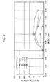
Fig. 2 ] It is a graph showing relations between dimensions of a retention protrusion and its retention force (iron-based material: SECC). - [
Fig. 3 ] It is a graph showing relations between dimensions of a retention protrusion and its retention force (iron-based material: SUS). - [
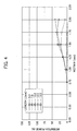
Fig. 4 ] It is a graph showing relations between dimensions of a retention protrusion and its retention force (aluminum-based material). - [
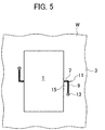
Fig. 5 ] It is an explanatory diagram (second example) of a method for cutting out a processed part from a workpiece. - [
Fig. 6 ] It is a graph showing relations between dimensions of a retention protrusion and its retention force (iron-based material: SECC). - [
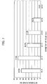
Fig. 7 ] It is a graph showing relations between dimensions of a retention protrusion and its retention force (iron-based material: SUS). - [
Fig. 8 ] It is a graph showing relations between dimensions of a retention protrusion and its retention force (aluminum-based material). - [
Fig. 9 ] It is an explanatory diagram (third example) of a method for cutting out a processed part from a workpiece. - [
Fig. 10 ] It is a photograph showing a state where the protrusion curves. - [
Fig. 11 ] It is a schematic perspective view of a laser processing machine. - [
Fig. 12 ] It is a block diagrams of a control device of the laser processing machine. - [
Fig. 13 ] It is a block diagrams of an automatic programing apparatus. - As shown in
Fig. 1 , a rectangular-shaped processedpart 1 is to be cut out from a sheet-shaped workpiece W by a laser cutting process. Here, while cutting out the processedpart 1 by the laser cutting process, acut slit 11 having an appropriate length is preliminarily formed by a laser processing at at least one position of ascrap 3 to be discarded after cutting out the processedpart 1. Each cut slit (cutting slit) 11 is formed along anoutline 5 of the processedpart 1 and formed by along slit 9 and ashort slit 7, and a short side opposite to theshort slit 7 is remained without being cut. Eachcut slit 11 has a slit-shape continuously formed by thelong slit 9 and theshort slit 7. After thecut slit 11 is formed, the laser cutting process is carried out along theoutline 5 of the processedpart 1. Note that theshort slit 7 has a length not larger than a thickness of the workpiece W. - When forming the
cut slit 11, a portion of thecut slit 11 is melted by heats of the laser cutting process. Then, a portion around thecut slit 11 is quickly cooled due to heat conduction after the laser cutting process of thecut slit 11. Further, when the processedpart 1 has been cut out from the workpiece W by carrying out the laser cutting process along theoutline 5, apressing protrusion 15 having a rectangular shape longwise in a direction along theoutline 5 is formed between thecut slit 11 and theoutline 5. A width H of a short side of thepressing protrusion 15 is not larger than the thickness of the workpiece W, and a length L of a long side thereof is three to eight times larger than the thickness. - Relations between dimensions (the width H and the length L [mm]) of the
pressing protrusion 15 and its retention force [N] are actually measured by using the workpiece W made of an iron-based material and an aluminum-based material. Note that the retention force is a retention force exerted by a singlepressing protrusion 15. A size of the cut-out processedpart 1 is a 65mm square, and one of two pairs of opposite two sides of the square is parallel to a roll-expanding direction of the workpiece (the roll-expanding direction will be explained later). Thepressing protrusion 15 is formed for each side one by one, and an end of thepressing protrusion 15 is positioned at the center of said each side. In addition, an extending direction of thepressing protrusion 15 coincides with a cutting direction of the outline 5 (the extending direction and the cutting direction will be explained later). - The iron-based material of the workpiece used for the measurements is SECC (electro galvanized zinc plated steel sheet) and SUS (stainless steel sheet). A thickness of SECC is 2.3mm, and a thickness of SUS is 2.0mm (an after-explained base-
end hole 13 is a mere pierced hole) . The measurement results (the relations between the dimensions of theretention protrusion 15 and its retention force) of SECC are shown by a graph inFig. 2 , and the measurement results of SUS are shown by a graph inFig. 3 . In addition, the aluminum-based material of the workpiece used for the measurements is a sheet member made of aluminum alloy A5052, and its thickness is 2.0mm (an after-explained base-end hole 13 is a mere pierced hole). The measurement results of the aluminum-based material are shown by a graph inFig. 4 . - As understood from the graphs in
Fig. 2 to Fig. 4 , the widths H 1.00mm to 1.75mm are good, and 1.25mm is better. In addition, the lengths L 7.5mm to 15mm are good, and 15mm is better. Note that, with respect to the length L, larger one than 15mm is not measured. In consideration of practical aspects such as the dimensions of the processed part 1 (the product to be cut out) and a plastic deformation amount of thepressing protrusion 15, it is determined that thepressing protrusion 15 longer than 15mm is not needed. - Residual stress exists in the
pressing protrusion 15 due to affection by heats of the laser cutting process of the cut slit 11. Then, the residual stress is released when theoutline 5 of the processedpart 1 has been laser-cut after the laser cutting process of the cut slit 11. As the result, a free end of thepressing protrusion 15 curves toward the processed part 1 (in a direction indicated by an arrow A) due to the residual stress (seeFig. 10 ), and thereby the free end presses a peripheral surface (cut face) of the processedpart 1. Therefore, by carrying out the laser cutting process along theoutline 5 of the processedpart 1 after preliminarily forming at least one cut slit 11 around the processedpart 1, the processedpart 1 can be retained by the curvature of thepressing protrusion 15 due to the residual stress so as not to drop off from the workpiece W. - Note that, in the first example shown in
Fig. 1 , the pressingprotrusion 15 is formed at each of four corners of the processedpart 1. Namely, the fourpressing protrusions 15 are formed in the first example. In the second example shown inFig. 5 , a pair of thepressing protrusions 15 is arranged oppositely to each other with the processedpart 1 interposed therebetween. Then, the pressing forces of the twopressing protrusions 15 are applied toward the processedpart 1, and opposed to each other. Therefore, the processedpart 1 is clamped by the pressing forces of the twopressing protrusions 15, and the processedpart 1 can be retained efficiently by the lesspressing protrusions 15. Note that thepressing protrusions 15 are formed longwise in the roll-expanding direction of the workpiece W. Advantages brought by forming thepressing protrusions 15 longwise in the roll-expanding direction of the workpiece W will be explained later. - For the laser cutting process of the cut slit 11, a base-
end hole 13 is laser-processed at a start end of the long slit 9 (a base end of the pressing protrusion 15) at first. The base-end hole 13 is a through hole. In addition, a radius of the base-end hole 13 is made larger than a radius of a pierced hole merely penetrated by piercing. Namely, the retention force can be improved by making a curvature support point (a portion from a closest position to theoutline 5 on an inner circumferential edge of the base-end hole 13 to a cutting slit of the outline 5) of thepressing protrusion 15 close to the processedpart 1 to enhance the inward curvature of thepressing protrusion 15. Note that the radius of the base-end hole 13 is determined so that the curvature support point of thepressing protrusion 15 doesn't get broken (ensures sufficient stiffness to keep the retention force) with its width got by subtracting the cutting slit width of theoutline 5 and the radius of the base-end hole 13 from the above-mentioned width H. For example, in a case where a thickness of a workpiece is 2.0mm or so, a radius of the base-end hole 13 may be 0.75mm and the width H may be 1.25mm. - After forming the base-
end hole 13, thelong slit 9 and theshort slit 7 are sequentially formed without deactivating a laser light and stopping the motions of the processing head. Just after forming the base-end hole 13, a portion around the base-end hole 13 is quickly cooled due to heat conduction outward from the position of the base-end hole 13 that is an initial position of the leaser processing. Therefore, the residual stress on a side of the free end of thepressing protrusion 15 becomes larger than the residual stress on a side of the base end thereof (near the base-end hole 13). Then, in a case of where the cutting direction of theoutline 5 of the processedpart 1 is made coincident with the extending direction of thepressing protrusion 15 to be formed (the cutting direction of the long slit 9), the pressingprotrusion 15 can be effectively curved in the direction indicated by the arrow A with the above -mentioned curvature support point serving as a base end. Note that, if the cutting direction of theoutline 5 and the extending direction of thepressing protrusion 15 are opposite to each other, the pressingprotrusion 15 can be curved in the direction indicated by the arrow A but its retention force becomes slightly smaller. - The relations between the diameter (radius × 2) of the base-
end hole 13 and the retention force [N] are actually measured by using the workpieces made of the iron-based material and the aluminum-based material. Note that the retention force is a retention force exerted by a singlepressing protrusion 15. A size of the cut-out processedpart 1 is a square whose each side is 65mm, and one of two pairs of opposite two sides of the square is parallel to the roll-expanding direction of the workpiece. Thepressing protrusion 15 is formed for each side one by one, and the end of thepressing protrusion 15 is positioned at the center of said each side. In addition, the extending direction of thepressing protrusion 15 coincides with the cutting direction of theoutline 5. - The iron-based material of the workpiece used for the measurements is SECC (electro galvanized zinc plated steel sheet) and SUS (stainless steel sheet). A thickness of SECC is 2.3mm, and a thickness of SUS is 2.0mm. The measurement results (relations between dimensions of the
retention protrusion 15 and its retention force) of SECC are shown by a graph inFig. 6 , and the measurement results of SUS are shown by a graph inFig. 7 . In addition, the aluminum-based material of the workpiece used for the measurements is a sheet member made of aluminum alloy A5052, and its thickness is 2.0mm. The measurement results of the aluminum-based material are shown by a graph inFig. 8 . In cases where the hole diameter of the base-end hole 13 is "N/A" in the graphs, the base-end hole 13 is a mere pierced hole and its hole diameter is not enlarged intentionally (the diameter of the pierced hole is 0.5mm). - As understood from the graphs, with respect to the ion-based material, a larger retention force can be obtained when forming the base-
end hole 13 having a diameter larger than that of a mere pierced hole. However, when the base-end hole 13 is too large, the stiffness of the above-mentioned curvature support point becomes insufficient and thereby the retention force reduces. With respect to SECC, the retention force increases by about 20% when the diameter of the base-end hole 13 is set to 1.5mm. With respect to SUS, the retention force increases by about 15% when the diameter of the base-end hole 13 is set to 1.0mm. However, with respect to the aluminum-based material, cases where the base-end hole 13 having a diameter larger than that of a mere pierced hole is not formed are better. - Note that it is sufficient that the width H and the length L of the
pressing protrusion 15 are a width and a length by which thepressing protrusion 15 curves during the laser cutting process of theoutline 5 of the processedpart 1 and thereby presses the processedpart 1 to retain the processedpart 1 by a friction resistant force due to the pressing force. Therefore, the width H and the length L of thepressing protrusion 15 may be set to a width and a length that are desired according to a size of the processedpart 1, the number of the cut slits 11 to be formed around the processedpart 1 and so on. - Note that the residual stress generated in the
pressing protrusion 15 during the formation of the cut slit 11 is reduced in some degree when thepressing protrusion 15 is heated during the laser cutting process of theoutline 5. In addition, the residual stress of thepressing protrusion 15 reduces in some degree as time goes on. However, necessary residual stress never gets dissipated while cutting the processedpart 1 and while separating the processedpart 1 from the workpiece W, and thereby the retention for the processedpart 1 is unaffected. - Further, the pressing
protrusion 15 curves more remarkably in the direction indicated by the arrow A when being formed longwise in the roll-expanding direction of the workpiece W than when being formed longwise in a direction perpendicular to the roll-expanding direction. Therefore, it is desired that the number of thepressing protrusions 15 longwise in the roll-expanding direction is increased in order to retain the processedpart 1 separably. However, the residual stress due to (heats of) the laser cutting process is more predominant than the residual stress due to the roll-expansion, so that there may be a case where the residual stress due to the roll-expansion can be ignored when the thickness of the workpiece W increases. - According to the present embodiment, the cut slit 11 (e.g. having an L-shaped in the present embodiment) is preliminarily formed along the
outline 5 of the processedpart 1 by carrying out the laser cutting process in a desired area around the pressingprotrusion 15 while cutting out the processedpart 1 from the workpiece W. Thepressing protrusion 15 presses the peripheral surface of the processedpart 1 due to the residual stress while laser-cutting theoutline 5 of the processedpart 1 and thereby retains it so that the processedpart 1 is not separated from the workpiece W (not separated from the scrap 3). Thepressing protrusion 15 is formed longwise along theoutline 5. - In a case of forming a
hole 1H inside the processed part 1 (the outline 5) as shown inFig. 9 (the third example), aninside portion 17 of thehole 1H becomes a scrap at last. In this case, the cut slit(s) 11 is preliminarily formed in theinside portion 17 and a laser cutting process is carried out in a desired area around the pressingprotrusion 15 while laser-cutting an outline of thehole 1H. By laser-cutting the outline of thehole 1H in this manner, the pressingprotrusion 15 presses an inner peripheral surface of thehole 1H and thereby theinside portion 17 is retained (theinside portion 17 is restricted from being separated from the processed part 1). - In the case of forming the
hole 1H inside the processedpart 1, it is preferable to laser-cut the outline of thehole 1H (the inside portion 17) in a state where the processedpart 1 is being unified with the workpiece W (before carrying out the laser cutting process of theoutline 5 of the processed part 1) and then laser-cut theoutline 5. Since the length of the outline of thehole 1H is overwhelmingly shorter than the length of theoutline 5 of the processed part 1 (in other words, an area of thehole 1H is overwhelmingly smaller than an area within theoutline 5 of the processedpart 1 / a weight of a cut piece inside thehole 1H is overwhelmingly smaller than a total weight of the cut piece inside thehole 1H and the processed part 1), the retention force by the pressingprotrusion 15 is more effective for an object having a smaller weight. Note that, if the difference of the weights is small or if there is restriction in carrying out the process, the outline of thehole 1H may be laser-cut after the laser cutting process of theoutline 5 of the processedpart 1. - Although general configuration of a laser cutting machine for carrying out a laser cutting process of a workpiece W is commonly known, configuration of a
laser cutting machine 21 according to the present embodiment will be explained hereinafter. As schematically shown inFig. 11 , thelaser cutting machine 21 includes a support frame (work table) 23 that supports a workpiece W. A gate-shaped movable frame (carriage) 25 is provided on thesupport frame 23 so as to be movable in an X-axis direction. Aslider 27 is provided on thecarriage 25 so as to be movable in a Y-axis direction. Alaser processing head 29 is provided on theslider 27 so as to be movable vertically (in a Z-axis direction). - The
laser processing head 29 is provided so as to be movable relative to the workpiece W in the X, Y and Z-axis directions. Setting of the relative position of thelaser processing head 29 in the X, Y and Z-axis directions is controlled by driving an X-axis servo motor, a Y-axis servo motor and a Z-axis servo motor (not shown in the drawings). Afiber laser oscillator 31 is provided as one example of a laser oscillator in order to laser-cut the workpiece W by thelaser processing head 29. Thefiber laser oscillator 31 and thelaser processing head 29 are connected with each other by anoptical fiber 33. - The
laser cutting machine 21 configured as explained above is controlled by its control device 35 (seeFig. 12 ). Operations of thelaser processing head 29 and operations of thelaser oscillator 31 are also controlled by thecontrol device 35, and thereby the processedpart 1 is cut out from the workpiece W as explained above. - The
control device 35 is configured of a computer, and includes a CPU, a RAM, a ROM, aninput device 37 and adisplay device 39. Anautomatic programming apparatus 41 that supplies (transmits) a processing program to thecontrol device 35 is connected with theinput device 37. Note that the processing program (NC data) generated by theautomatic programming apparatus 41 can be supplied to thecontrol device 35 by an appropriate memory media. - The
control device 35 includes aprocessing program memory 43 that stores the processing program. In addition, thecontrol device 35 also includes aprogram analyzer 45. Theprogram analyzer 45 preliminarily reads out the processing program stored in theprocessing program memory 43 and then analyzes it, and then calculates an arrangement position on the workpiece W, a shape and dimensions of the processedpart 1. - Further, the
control device 35 also includes anarithmetic section 47 that executes various arithmetic calculations. In thearithmetic section 47, included is a weightarithmetic section 47A that calculates a weight of the processedpart 1 and also calculates a barycentric position and/or a center position of the processedpart 1 with referring to a shape and dimensions of the processedpart 1 obtained by analyzing the processing program, a material and a thickness of the workpiece W and so on. In addition, in thearithmetic section 47, also included is a press-force arithmetic section 47B that calculates a pressing force of the pressing protrusion(s) 15 to be arranged around the processedpart 1. - The press-
force arithmetic section 47B refers to the width H and the length L of thepressing protrusion 15 and a laser cutting condition and then calculates the pressing force P = F(H, L, laser cutting condition) [f(a, b, c) is a function with variables a, b and c]. In the laser cutting condition, a laser output power, a processing speed, a focal position, a duty ratio of a pulse output, a pressure of assist gas, a diameter of a head nozzle and so on are included. Therefore, it is hard to determine the laser cutting condition inclusively. Then, in order to determine the laser cutting condition inclusively, thecontrol device 35 also includes a cuttingcondition parameter memory 57. - Various parameters are stored in the cutting
condition parameter memory 57. Namely, residual stresses are preliminarily measured at the laser cutting processes by varying a processing speed, a focal position, a duty ratio of a pulse output, a pressure of assist gas, a diameter of a head nozzle and so on for each set of a material and a thickness of the workpiece W, and these various laser processing conditions are stored in the cuttingcondition parameter memory 57 as parameters. Therefore, an appropriate parameter(s) can be selected from the cuttingcondition parameter memory 57 according to the laser cutting condition. The pressing force P is calculated based on the selected parameters. - Further, in the
arithmetic section 47, also included is anumber arithmetic section 47C that calculates the number of thepressing protrusions 15 to be provided based on the calculation result of the weightarithmetic section 47A and the calculation result of the press-force arithmetic section 47B. If a calculation result includes a digit(s) after the decimal point, thenumber arithmetic section 47C carries up the calculation result into an integer. - Furthermore, the
control device 35 also includes apressing protrusion arranger 49. Thepressing protrusion arranger 49 arranges thepressing protrusions 15 around the processedpart 1 based on data analyzed by theprogram analyzer 45 and then stored in an analyzeddata memory 45A, such as the arrangement position, the shape and the dimensions of the processedpart 1 and the calculation result of thenumber arithmetic section 47C. - For example, in a case of providing one pressing
protrusion 15, thepressing protrusion arranger 49 arranges thepressing protrusion 15 at a position where a distance from the barycentric position or the center position of the processedpart 1 to theoutline 5 is made minimum so that the pressing force of thepressing protrusion 15 is directed in a direction toward the barycentric position or the center position. In a case of providing two or morepressing protrusions 15, it arranges thepressing protrusions 15 around the processedpart 1 at even intervals along its peripheral direction. - There may be another way in which the processed
part 1 is displayed on adisplay screen 39A of thedisplay device 39 after the calculation of the number of thepressing protrusions 15 by thenumber arithmetic section 47C, and then thepressing protrusions 15 are arranged around the processedpart 1 by operating the input device such as a mouse. In this case, it is possible to increase the number of thepressing protrusions 15 more than the number calculated by thenumber arithmetic section 47C. In addition, in this case, thedisplay device 39, the mouse and so on function also as thepressing protrusion arranger 49. - The shape and the dimensions of the
pressing protrusion 15, i.e. the lengths of the long side and the short side of the rectangular shape are preliminarily determined through experiments as parameters in association with the material and the thickness of the workpiece W and the shape and the dimensions of the processedpart 1. In addition, the parameters for determining the shape and the dimensions of thepressing protrusion 15 are stored in aworkpiece parameter memory 51. Therefore, an appropriate shape and appropriate dimensions of thepressing protrusion 15 are selected from theworkpiece parameter memory 51 according to the material and the thickness of the workpiece W. - When the shape and the dimensions of the pressing protrusion(s) 15 have been selected, a processing program for the laser cutting process of the
pressing protrusion 15 is generated according to the shape and the dimensions of thepressing protrusion 15 that have been selected. Namely, thecontrol device 35 includes a lasercutting program memory 53 that preliminarily stores various laser cutting programs for various sets of the shape and the dimensions of thepressing protrusion 15. When the shape and the dimensions of the pressing protrusion(s) 15 have been selected by the parameters, aprocessing program generator 55 selects an appropriate laser cutting program from the lasercutting program memory 53 according to the determined parameters, and then stores it in theprocessing program memory 43. - Further, the
control device 35 includes anaxial motion controller 59. Theaxial motion controller 59 controls axial motions of thelaser processing head 29 in the X, Y and Z-axis directions according to the processing program stored in theprocessing program memory 43. - For example, in a case of cutting out the processed
part 1 from the workpiece W as shown inFig. 1 , the processing program is analyzed by theprogram analyzer 45 when the processing program generated by theautomatic programming apparatus 41 has been stored in theprocessing program memory 43. Then, the material and the thickness of the workpiece W and the shape and the dimensions of the processedpart 1 are stored in an analyzeddata memory 45A as analyzed data. - When the processing program has been analyzed, the weight
arithmetic section 47A calculates a weight of the processedpart 1 based on the analyzed data (the material and the thickness of the workpiece W and the shape and the dimensions of the processed part 1). In addition, the appropriate shape and the appropriate dimensions of thepressing protrusion 15 are selected from theworkpiece parameter memory 51 based on the analyzed data. - When the appropriate shape and the appropriate dimensions of the
pressing protrusion 15 have been selected from theworkpiece parameter memory 51, an appropriate laser cutting condition for the laser cutting process of thepressing protrusion 15 is selected from the cuttingcondition parameter memory 57. Then, theprocessing program generator 55 generates the laser cutting program of thepressing protrusion 15 based on the selected laser cutting condition and the shape and the dimensions of thepressing protrusion 15, and stores it in theprocessing program memory 43. In addition, the press-force arithmetic section 47B calculates the pressing force of thepressing protrusion 15 based on the selected laser cutting condition and the width H and the length L of thepressing protrusion 15. - Based on the calculation result of the weight
arithmetic section 47A and the calculation result of the press-force arithmetic section 47B, thenumber arithmetic section 47C calculates the required number of thepressing protrusions 15 for pressing and retaining the processedpart 1 so as to restrict the processedpart 1 from dropping off from the workpiece W. Note that, without using the press-force arithmetic section 47B, the required number of canonically-shapedpressing protrusions 15 with respect to a weight of a retention object may be preliminarily determined and then the required number of thepressing protrusions 15 may be calculated based on the weight of the retention object. - When the number of the
pressing protrusions 15 has been calculated by thenumber arithmetic section 47C, thepressing protrusions 15 are arranged around the processedpart 1 by thepressing protrusion arranger 49. Note that thenumber arithmetic section 47C calculates the required minimum number. Therefore, for example, the pressing protrusion(s) 15 can be additionally arranged around the processedpart 1 displayed on thedisplay screen 39A of thedisplay device 39 by the input device such as a mouse. - When the arrangement positions of the
pressing protrusions 15 have been set, the cut slits 11 are laser-cut according to the arrangement positions of thepressing protrusions 15. Then, after the laser cutting of the cut slits 11, theoutline 5 of the processedpart 1 is laser-cut according to the processing program stored in theprocessing program memory 43. When theoutline 5 has been laser-cut in this manner, the processedpart 1 is pressed and retained by the pluralpressing protrusions 15 arranged around the processedpart 1 as explained above so as not to drop off from the workpiece W. - In the above explanations, the processing program generated by the
automatic programming apparatus 41 is stored in theprocessing program memory 43 of thecontrol device 35, and theprogram analyzer 45 of thecontrol device 35 analyzes this stored processing program. However, there may be another way in which theautomatic programming apparatus 41 analyzes a laser cutting program generated by itself, and then a program transferrer 63 (seeFig. 13 ) of theautomatic programming apparatus 41 transfers this analyzed laser cutting program to thecontrol device 35. - The
automatic programming apparatus 41 in this case will be explained. Note that components identical or equivalent to the already-explained components of thecontrol device 35 of thelaser cutting machine 21 are labelled with the identical reference signs and their redundant explanations are omitted. - As shown in
Fig. 13 , theautomatic programming apparatus 41 includes anarithmetic section 47 equivalent to thearithmetic section 47 of thecontrol device 35. Therefore, when an operator inputs a shape and dimensions of the processedpart 1 through aCAD 61, theautomatic programming apparatus 41 calculates a weight of the processedpart 1, and a pressing force and the number of thepressing protrusions 15 to be arranged around the processed part 1 (a weightarithmetic section 47A, a press-force arithmetic section 47B and anumber arithmetic section 47C). Then, theautomatic programming apparatus 41 calculates the number of thepressing protrusions 15, and apressing protrusion arranger 49 arranges thepressing protrusions 15 around the processedpart 1. - When the arrangement positions of the
pressing protrusions 15 have been set around the processedpart 1, aprocessing program generator 55 generates a laser cutting program for carrying out a laser cutting processing of thepressing protrusions 15 and the processedpart 1. Theprocessing program generator 55 stores a laser cutting program generated by itself in aprocessing program memory 43. The program transferrer 63 transfers the laser cutting program stored in theprocessing program memory 43 to thecontrol device 35. - Therefore, the
control device 35 laser-cuts the workpiece W by controlling operations of thelaser processing head 29 according to the laser cutting program generated by theautomatic programming apparatus 41. - Note that, in the above embodiments, the length L of the
pressing protrusion 15 is made three to eight times larger than the thickness of the workpiece W. If it is smaller than three times large value, the inward curvature of thepressing protrusion 15 decreases and thereby an sufficient pressing force cannot be got. On the other hand, if it exceeds over eight times large value, a curvature of thepressing protrusion 15 other than inward is subject to be generated. For example, the pressingprotrusion 15 becomes subject to be twisted due to the weight of the processed part, and thereby the inward pressing force cannot be got effectively. - In addition, the measurements of the retention force are done by using the workpieces W whose thickness is 2.0mm and 2.3mm in the above embodiments, but it is still preferable, even if its thickness is larger, that the width H of the
pressing protrusion 15 is made smaller than the thickness of the workpiece W and the length L of thepressing protrusion 15 is made three to eight times larger than the thickness of the workpiece W. - According to the above embodiments, the
control device 35 or theautomatic programming apparatus 41 arranges one or pluralpressing protrusions 15 around the processedpart 1 to be cut out from the sheet-shaped workpiece W. The curving pressing protrusion(s) 15 retains the processedpart 1 so as not to drop it off from the workpiece W. - The entire contents of a
Japanese Patent Application No. 2017-55555
Claims (15)
- A laser cutting method for cutting out a processed part (1) from a sheet-shaped workpiece (W), the method comprising:(a) preliminarily laser-cutting a cut slit (11) along an outline of the processed part (1) to be cut out from the workpiece (W) such that only one of both ends of the cut slit (11) is positioned on the outline (5) of the processed part (1) to be cut out;(b) carrying out a laser cutting process along the outline (5) of the processed part (1) to cut out the processed part (1), such that a pressing protrusion (15) is formed longwise along the outline (5) between the cut slit (11) and the outline (5) of the processed part (1), the pressing protrusion (15) including a free end that presses the peripheral surface of the processed part (1),wherein the pressing protrusion (15) is curved due to the laser cutting process along the outline (5) of the processed part (1) and then presses a peripheral surface of the processed part (1).
- The laser cutting method according to claim 1, further comprising,
in a case of forming a hole (1H) inside the processed part (1), preliminarily laser-cutting the cut slit (11) of the pressing protrusion (15) around a scrap (17) within the hole (1H), the pressing protrusion (15) being curved due to a laser cutting process along an outline of the hole (1H) and then pressing an inner peripheral surface of the hole (1H). - The laser cutting method according to claim 2, wherein
the processed part (1) is laser-cut after laser-cutting the scrap (17) within the hole (1H). - The laser cutting method according to claim 1, wherein
the pressing protrusion (15) has a rectangular shape. - The laser cutting method according to claim 4, wherein
the pressing protrusion (15) is longwise in a roll-expanding direction of the workpiece (W). - The laser cutting method according to claim 4, wherein
a base-end hole (13) is laser-processed at a base end of the pressing protrusion (15), and then the cut slit (11) is laser-cut from the base-end hole (13) such that the base end hole (13) is positioned at the other of the both ends of the cut slit. - The laser cutting method according to claim 6, wherein
a curvature support point of the pressing protrusion (15) is made close to the outline (5) by making a radius of the base-end hole (13) large. - The laser cutting method according to claim 4, wherein
a width (H) of the pressing protrusion (15) is not more than a thickness of the workpiece (W). - The laser cutting method according to claim 4, wherein
a length (L) of the pressing protrusion (15) is three to eight times larger than a thickness of the workpiece (W). - A laser cutting machine (21) for cutting out a processed part (1) from a sheet-shaped workpiece (W), the machine (21) comprising:a laser processing head (29) movable relative to the workpiece in X, Y and Z-axis directions;characterised bya control device (35) for controlling motions of the laser processing head (29) to cut the processed part from the shaped workpiece (W) according to the method of claim 1,wherein the control device (35) comprises:a processing program memory (43) that stores a processing program for laser-cutting the processed part (1);a program analyzer (45) that analyzes a shape and dimensions of the processed part (1) by analyzing the processing program;a weight arithmetic section (47A) that calculates a weight of the processed part (1) based on the analyzed shape and the analyzed dimensions of the processed part (1) and a thickness of the workpiece (W);the control device (35) further comprises:a number arithmetic section (47C) that calculates the number of pressing protrusions (15) based on a calculation result of the weight arithmetic section (47A), each of the pressing protrusions (15) being curved due to a laser cutting process along an outline (5) of the processed part (1) and then pressing a peripheral surface of the processed part (1);a pressing protrusion arranger (49) that arranges the pressing protrusions (15) around the processed part (1) based on a calculation result of the number arithmetic section (47C);a processing program generator (55) that generates a laser cutting program for forming the pressing protrusions (15) at positions arranged by the pressing protrusion arranger (49);the processing program memory (43) that stores the laser cutting program generated by the processing program generator (55); andan axial motion controller (59) that controls axial motions of the laser processing head (29) according to the laser cutting program stored in the processing program memory (43).
- The laser cutting machine (21) according to claim 10, wherein
the control device (35) comprises a cutting condition parameter memory (57) that stores various laser processing conditions as parameters. - The laser cutting machine (21) according to claim 10 or 11, wherein
the control device (35) comprises a workpiece parameter memory (51) that stores parameters of a width (H) and a length (L) of the pressing protrusions (15) in association with a material and the thickness of the workpiece (W). - An automatic programming apparatus (41) of a laser cutting machine (21), the apparatus (41) comprising:a weight arithmetic section (47A) that calculates a weight of a processed part (1) based on a shape and dimensions of the processed part (1) that are input though a CAD (61) and a thickness of a workpiece (W);a number arithmetic section (47C) that calculates the number of pressing protrusions (15) based on a calculation result of the weight arithmetic section (47A), each of the pressing protrusions (15) being curved due to a laser cutting process along an outline (5) of the processed part (1) and then pressing a peripheral surface of the processed part (1);a pressing protrusion arranger (49) that arranges the pressing protrusions (15) around the processed part (1) based on a calculation result of the number arithmetic section (47C);a processing program generator (55) that generates a laser cutting program for forming the pressing protrusions (15) at positions arranged by the pressing protrusion arranger (49) and laser-cutting the processed part (1);a processing program memory (43) that stores the laser cutting program generated by the processing program generator (55); anda program transferrer (63) that transfers the laser cutting program stored in the processing program memory (43) to a control device (35) of the laser cuttingmachine (21) for controlling motions of the laser processing head to cut the processed part from the sheet shape workpiece according to the method of claim 1.
- The automatic programming apparatus (41) according to claim 13, further comprising:
a cutting condition parameter memory (57) that stores various laser processing conditions as parameters. - The automatic programming apparatus (41) according to claim 13 or 14, further comprising:
a workpiece parameter memory (51) that stores parameters of a width (H) and a length (L) of the pressing protrusions (15) in association with a material and the thickness of the workpiece (W).
Applications Claiming Priority (2)
| Application Number | Priority Date | Filing Date | Title |
|---|---|---|---|
| JP2017055555 | 2017-03-22 | ||
| PCT/JP2018/010861 WO2018174020A1 (en) | 2017-03-22 | 2018-03-19 | Laser cutting method and device, and automatic programming device |
Publications (3)
| Publication Number | Publication Date |
|---|---|
| EP3603874A1 EP3603874A1 (en) | 2020-02-05 |
| EP3603874A4 EP3603874A4 (en) | 2020-04-29 |
| EP3603874B1 true EP3603874B1 (en) | 2022-01-05 |
Family
ID=63585383
Family Applications (1)
| Application Number | Title | Priority Date | Filing Date |
|---|---|---|---|
| EP18771741.8A Active EP3603874B1 (en) | 2017-03-22 | 2018-03-19 | Laser cutting method and device, and automatic programming device |
Country Status (4)
| Country | Link |
|---|---|
| US (1) | US10974346B2 (en) |
| EP (1) | EP3603874B1 (en) |
| JP (1) | JP6524368B2 (en) |
| WO (1) | WO2018174020A1 (en) |
Families Citing this family (6)
| Publication number | Priority date | Publication date | Assignee | Title |
|---|---|---|---|---|
| JP6638043B1 (en) * | 2018-09-21 | 2020-01-29 | 株式会社アマダホールディングス | Laser cutting method and device, and automatic programming device |
| DE102020205680A1 (en) | 2020-05-06 | 2021-11-11 | Trumpf Werkzeugmaschinen Gmbh + Co. Kg | Method for determining a minimum width and an attachment position of a microjoint and method for machining a workpiece |
| JP7312925B1 (en) * | 2022-03-25 | 2023-07-21 | 株式会社アマダ | Laser processing path allocation method, laser processing method, and laser processing path allocation device |
| JP7584477B2 (en) | 2022-08-08 | 2024-11-15 | 株式会社アマダ | Laser Cutting Method |
| JP7828856B2 (en) * | 2022-08-25 | 2026-03-12 | 株式会社アマダ | Product unloading device and product unloading method |
| CN116021169B (en) * | 2022-12-30 | 2026-04-10 | 长飞光坊(武汉)科技有限公司 | A laser cutting method and apparatus |
Family Cites Families (16)
| Publication number | Priority date | Publication date | Assignee | Title |
|---|---|---|---|---|
| CH659415A5 (en) * | 1983-06-09 | 1987-01-30 | Agie Ag Ind Elektronik | METHOD FOR SECURING CUT OUT PIECES IN EDM CUTTING AND APPLICATION OF THE METHOD. |
| JP2737363B2 (en) * | 1990-06-05 | 1998-04-08 | 三菱電機株式会社 | NC program generation method |
| DE4116868C2 (en) * | 1991-05-23 | 1995-07-27 | Agie Ag Ind Elektronik | Process for machining workpieces, in particular for EDM machining of workpieces using a wire |
| JPH05245671A (en) * | 1992-03-10 | 1993-09-24 | Amada Co Ltd | Laser beam machining method and machining head device |
| JP2743758B2 (en) | 1993-02-12 | 1998-04-22 | 澁谷工業株式会社 | Laser processing method |
| JPH07103807A (en) * | 1993-09-30 | 1995-04-21 | Shibuya Kogyo Co Ltd | Weight calculating method for work |
| JPH0819918A (en) * | 1994-07-07 | 1996-01-23 | Mitsubishi Electric Corp | Wire electric discharge machining method and apparatus |
| IT1292330B1 (en) * | 1997-05-27 | 1999-01-29 | Crea Srl | PROCEDURE FOR THE PRODUCTION OF FOLDED SHEET METAL PIECES |
| EP2401122B1 (en) * | 2009-02-24 | 2014-09-17 | Bystronic Laser AG | Process for working of work-pieces by means of cutting fluid-jet |
| JP5891021B2 (en) * | 2011-12-05 | 2016-03-22 | 株式会社アマダホールディングス | Laser processing method, automatic programming apparatus and processing system |
| JP5909355B2 (en) * | 2011-12-22 | 2016-04-26 | 株式会社アマダホールディングス | Automatic programming apparatus and method for laser processing machine and laser processing system |
| DE112012006087B4 (en) * | 2012-04-26 | 2022-05-19 | Mitsubishi Electric Corporation | Control device and processing method for electric wire discharge machine |
| JP5911912B2 (en) * | 2014-06-04 | 2016-04-27 | ファナック株式会社 | Machining path drawing device for wire electric discharge machine |
| JP2017055555A (en) | 2015-09-09 | 2017-03-16 | 株式会社日立製作所 | Inverter device and control system for three-phase motor having the same |
| EP3287223B1 (en) * | 2016-07-28 | 2021-01-13 | Fanuc Corporation | Wire electrical discharge machining method |
| JP6420398B1 (en) * | 2017-04-07 | 2018-11-07 | ファナック株式会社 | Control device, wire electric discharge machine, program editing device, and control method |
-
2018
- 2018-03-19 US US16/490,180 patent/US10974346B2/en active Active
- 2018-03-19 WO PCT/JP2018/010861 patent/WO2018174020A1/en not_active Ceased
- 2018-03-19 EP EP18771741.8A patent/EP3603874B1/en active Active
- 2018-03-19 JP JP2019506200A patent/JP6524368B2/en active Active
Non-Patent Citations (1)
| Title |
|---|
| None * |
Also Published As
| Publication number | Publication date |
|---|---|
| JP6524368B2 (en) | 2019-06-05 |
| US10974346B2 (en) | 2021-04-13 |
| JPWO2018174020A1 (en) | 2019-06-27 |
| US20200001401A1 (en) | 2020-01-02 |
| EP3603874A4 (en) | 2020-04-29 |
| WO2018174020A1 (en) | 2018-09-27 |
| EP3603874A1 (en) | 2020-02-05 |
Similar Documents
| Publication | Publication Date | Title |
|---|---|---|
| US10974346B2 (en) | Laser cutting method and machine, and automatic programing apparatus | |
| JP3162255B2 (en) | Laser processing method and apparatus | |
| EP3069813B1 (en) | Laser welding condition determination method and laser welding device | |
| US20220152744A1 (en) | Beam machining plate-like or tubular workpieces | |
| US20230054278A1 (en) | Method for determining a minimum width and an attachment position of a microjoint and method for machining a workpiece | |
| EP3854514B1 (en) | Laser cutting method and automatic programming device | |
| EP3922377A1 (en) | Coiling machine, method for manufacturing coil spring, and coil spring | |
| US11045908B2 (en) | Piercing workpieces by a laser beam and an associated laser processing machine | |
| EP3871827B1 (en) | Laser machining device and laser machining method | |
| JP5909355B2 (en) | Automatic programming apparatus and method for laser processing machine and laser processing system | |
| JP2008290135A (en) | Laser beam machining apparatus and laser beam machining method | |
| JP2020082287A (en) | Welding robot | |
| JP6963345B1 (en) | Processing equipment, relative positional relationship identification method and laser light intensity identification method | |
| US12122060B2 (en) | Method and machining tool for cutting workpieces and associated computer program product | |
| JP7474874B2 (en) | Method for generating a workpiece part from a plate-shaped workpiece, as well as a data processing program and a processing machine for generating said workpiece part | |
| CN109070274B (en) | Laser processing apparatus and laser processing method | |
| Pramanik et al. | A parametric study of kerf deviation in fiber laser micro cutting on Ti6Al4V Superalloy | |
| EP0708697B1 (en) | Welding method | |
| JP2024022949A (en) | Laser cutting method | |
| JP6160815B2 (en) | Laser processing method and laser processing system | |
| JP2021142532A (en) | Laser/punch composite system | |
| EP4737048A1 (en) | Laser welding apparatus | |
| EP3677375B1 (en) | Joint body, manufacturing method for joint body, and manufacturing apparatus for joint body | |
| JP2026507274A (en) | Computer-implemented method for determining cutting gap width for laser cutting processes | |
| CN117999147A (en) | Laser processing method and laser processing machine |
Legal Events
| Date | Code | Title | Description |
|---|---|---|---|
| STAA | Information on the status of an ep patent application or granted ep patent |
Free format text: STATUS: THE INTERNATIONAL PUBLICATION HAS BEEN MADE |
|
| PUAI | Public reference made under article 153(3) epc to a published international application that has entered the european phase |
Free format text: ORIGINAL CODE: 0009012 |
|
| STAA | Information on the status of an ep patent application or granted ep patent |
Free format text: STATUS: REQUEST FOR EXAMINATION WAS MADE |
|
| 17P | Request for examination filed |
Effective date: 20191016 |
|
| AK | Designated contracting states |
Kind code of ref document: A1 Designated state(s): AL AT BE BG CH CY CZ DE DK EE ES FI FR GB GR HR HU IE IS IT LI LT LU LV MC MK MT NL NO PL PT RO RS SE SI SK SM TR |
|
| AX | Request for extension of the european patent |
Extension state: BA ME |
|
| A4 | Supplementary search report drawn up and despatched |
Effective date: 20200330 |
|
| RIC1 | Information provided on ipc code assigned before grant |
Ipc: B23K 26/08 20140101ALI20200324BHEP Ipc: B23K 26/38 20140101AFI20200324BHEP Ipc: G05B 19/4097 20060101ALI20200324BHEP |
|
| DAV | Request for validation of the european patent (deleted) | ||
| DAX | Request for extension of the european patent (deleted) | ||
| STAA | Information on the status of an ep patent application or granted ep patent |
Free format text: STATUS: EXAMINATION IS IN PROGRESS |
|
| 17Q | First examination report despatched |
Effective date: 20210111 |
|
| GRAP | Despatch of communication of intention to grant a patent |
Free format text: ORIGINAL CODE: EPIDOSNIGR1 |
|
| STAA | Information on the status of an ep patent application or granted ep patent |
Free format text: STATUS: GRANT OF PATENT IS INTENDED |
|
| INTG | Intention to grant announced |
Effective date: 20210728 |
|
| GRAS | Grant fee paid |
Free format text: ORIGINAL CODE: EPIDOSNIGR3 |
|
| GRAA | (expected) grant |
Free format text: ORIGINAL CODE: 0009210 |
|
| STAA | Information on the status of an ep patent application or granted ep patent |
Free format text: STATUS: THE PATENT HAS BEEN GRANTED |
|
| AK | Designated contracting states |
Kind code of ref document: B1 Designated state(s): AL AT BE BG CH CY CZ DE DK EE ES FI FR GB GR HR HU IE IS IT LI LT LU LV MC MK MT NL NO PL PT RO RS SE SI SK SM TR |
|
| REG | Reference to a national code |
Ref country code: GB Ref legal event code: FG4D |
|
| REG | Reference to a national code |
Ref country code: CH Ref legal event code: EP |
|
| REG | Reference to a national code |
Ref country code: AT Ref legal event code: REF Ref document number: 1460093 Country of ref document: AT Kind code of ref document: T Effective date: 20220115 |
|
| REG | Reference to a national code |
Ref country code: DE Ref legal event code: R096 Ref document number: 602018029174 Country of ref document: DE |
|
| REG | Reference to a national code |
Ref country code: IE Ref legal event code: FG4D |
|
| REG | Reference to a national code |
Ref country code: LT Ref legal event code: MG9D |
|
| REG | Reference to a national code |
Ref country code: NL Ref legal event code: MP Effective date: 20220105 |
|
| REG | Reference to a national code |
Ref country code: AT Ref legal event code: MK05 Ref document number: 1460093 Country of ref document: AT Kind code of ref document: T Effective date: 20220105 |
|
| PG25 | Lapsed in a contracting state [announced via postgrant information from national office to epo] |
Ref country code: NL Free format text: LAPSE BECAUSE OF FAILURE TO SUBMIT A TRANSLATION OF THE DESCRIPTION OR TO PAY THE FEE WITHIN THE PRESCRIBED TIME-LIMIT Effective date: 20220105 |
|
| PG25 | Lapsed in a contracting state [announced via postgrant information from national office to epo] |
Ref country code: SE Free format text: LAPSE BECAUSE OF FAILURE TO SUBMIT A TRANSLATION OF THE DESCRIPTION OR TO PAY THE FEE WITHIN THE PRESCRIBED TIME-LIMIT Effective date: 20220105 Ref country code: RS Free format text: LAPSE BECAUSE OF FAILURE TO SUBMIT A TRANSLATION OF THE DESCRIPTION OR TO PAY THE FEE WITHIN THE PRESCRIBED TIME-LIMIT Effective date: 20220105 Ref country code: PT Free format text: LAPSE BECAUSE OF FAILURE TO SUBMIT A TRANSLATION OF THE DESCRIPTION OR TO PAY THE FEE WITHIN THE PRESCRIBED TIME-LIMIT Effective date: 20220505 Ref country code: NO Free format text: LAPSE BECAUSE OF FAILURE TO SUBMIT A TRANSLATION OF THE DESCRIPTION OR TO PAY THE FEE WITHIN THE PRESCRIBED TIME-LIMIT Effective date: 20220405 Ref country code: LT Free format text: LAPSE BECAUSE OF FAILURE TO SUBMIT A TRANSLATION OF THE DESCRIPTION OR TO PAY THE FEE WITHIN THE PRESCRIBED TIME-LIMIT Effective date: 20220105 Ref country code: HR Free format text: LAPSE BECAUSE OF FAILURE TO SUBMIT A TRANSLATION OF THE DESCRIPTION OR TO PAY THE FEE WITHIN THE PRESCRIBED TIME-LIMIT Effective date: 20220105 Ref country code: ES Free format text: LAPSE BECAUSE OF FAILURE TO SUBMIT A TRANSLATION OF THE DESCRIPTION OR TO PAY THE FEE WITHIN THE PRESCRIBED TIME-LIMIT Effective date: 20220105 Ref country code: BG Free format text: LAPSE BECAUSE OF FAILURE TO SUBMIT A TRANSLATION OF THE DESCRIPTION OR TO PAY THE FEE WITHIN THE PRESCRIBED TIME-LIMIT Effective date: 20220405 |
|
| PG25 | Lapsed in a contracting state [announced via postgrant information from national office to epo] |
Ref country code: PL Free format text: LAPSE BECAUSE OF FAILURE TO SUBMIT A TRANSLATION OF THE DESCRIPTION OR TO PAY THE FEE WITHIN THE PRESCRIBED TIME-LIMIT Effective date: 20220105 Ref country code: LV Free format text: LAPSE BECAUSE OF FAILURE TO SUBMIT A TRANSLATION OF THE DESCRIPTION OR TO PAY THE FEE WITHIN THE PRESCRIBED TIME-LIMIT Effective date: 20220105 Ref country code: GR Free format text: LAPSE BECAUSE OF FAILURE TO SUBMIT A TRANSLATION OF THE DESCRIPTION OR TO PAY THE FEE WITHIN THE PRESCRIBED TIME-LIMIT Effective date: 20220406 Ref country code: FI Free format text: LAPSE BECAUSE OF FAILURE TO SUBMIT A TRANSLATION OF THE DESCRIPTION OR TO PAY THE FEE WITHIN THE PRESCRIBED TIME-LIMIT Effective date: 20220105 Ref country code: AT Free format text: LAPSE BECAUSE OF FAILURE TO SUBMIT A TRANSLATION OF THE DESCRIPTION OR TO PAY THE FEE WITHIN THE PRESCRIBED TIME-LIMIT Effective date: 20220105 |
|
| PG25 | Lapsed in a contracting state [announced via postgrant information from national office to epo] |
Ref country code: IS Free format text: LAPSE BECAUSE OF FAILURE TO SUBMIT A TRANSLATION OF THE DESCRIPTION OR TO PAY THE FEE WITHIN THE PRESCRIBED TIME-LIMIT Effective date: 20220505 |
|
| REG | Reference to a national code |
Ref country code: DE Ref legal event code: R097 Ref document number: 602018029174 Country of ref document: DE |
|
| PG25 | Lapsed in a contracting state [announced via postgrant information from national office to epo] |
Ref country code: SM Free format text: LAPSE BECAUSE OF FAILURE TO SUBMIT A TRANSLATION OF THE DESCRIPTION OR TO PAY THE FEE WITHIN THE PRESCRIBED TIME-LIMIT Effective date: 20220105 Ref country code: SK Free format text: LAPSE BECAUSE OF FAILURE TO SUBMIT A TRANSLATION OF THE DESCRIPTION OR TO PAY THE FEE WITHIN THE PRESCRIBED TIME-LIMIT Effective date: 20220105 Ref country code: RO Free format text: LAPSE BECAUSE OF FAILURE TO SUBMIT A TRANSLATION OF THE DESCRIPTION OR TO PAY THE FEE WITHIN THE PRESCRIBED TIME-LIMIT Effective date: 20220105 Ref country code: MC Free format text: LAPSE BECAUSE OF FAILURE TO SUBMIT A TRANSLATION OF THE DESCRIPTION OR TO PAY THE FEE WITHIN THE PRESCRIBED TIME-LIMIT Effective date: 20220105 Ref country code: EE Free format text: LAPSE BECAUSE OF FAILURE TO SUBMIT A TRANSLATION OF THE DESCRIPTION OR TO PAY THE FEE WITHIN THE PRESCRIBED TIME-LIMIT Effective date: 20220105 Ref country code: DK Free format text: LAPSE BECAUSE OF FAILURE TO SUBMIT A TRANSLATION OF THE DESCRIPTION OR TO PAY THE FEE WITHIN THE PRESCRIBED TIME-LIMIT Effective date: 20220105 Ref country code: CZ Free format text: LAPSE BECAUSE OF FAILURE TO SUBMIT A TRANSLATION OF THE DESCRIPTION OR TO PAY THE FEE WITHIN THE PRESCRIBED TIME-LIMIT Effective date: 20220105 |
|
| REG | Reference to a national code |
Ref country code: CH Ref legal event code: PL |
|
| PLBE | No opposition filed within time limit |
Free format text: ORIGINAL CODE: 0009261 |
|
| STAA | Information on the status of an ep patent application or granted ep patent |
Free format text: STATUS: NO OPPOSITION FILED WITHIN TIME LIMIT |
|
| PG25 | Lapsed in a contracting state [announced via postgrant information from national office to epo] |
Ref country code: AL Free format text: LAPSE BECAUSE OF FAILURE TO SUBMIT A TRANSLATION OF THE DESCRIPTION OR TO PAY THE FEE WITHIN THE PRESCRIBED TIME-LIMIT Effective date: 20220105 |
|
| REG | Reference to a national code |
Ref country code: BE Ref legal event code: MM Effective date: 20220331 |
|
| 26N | No opposition filed |
Effective date: 20221006 |
|
| PG25 | Lapsed in a contracting state [announced via postgrant information from national office to epo] |
Ref country code: LU Free format text: LAPSE BECAUSE OF NON-PAYMENT OF DUE FEES Effective date: 20220319 Ref country code: LI Free format text: LAPSE BECAUSE OF NON-PAYMENT OF DUE FEES Effective date: 20220331 Ref country code: IE Free format text: LAPSE BECAUSE OF NON-PAYMENT OF DUE FEES Effective date: 20220319 Ref country code: CH Free format text: LAPSE BECAUSE OF NON-PAYMENT OF DUE FEES Effective date: 20220331 |
|
| PG25 | Lapsed in a contracting state [announced via postgrant information from national office to epo] |
Ref country code: SI Free format text: LAPSE BECAUSE OF FAILURE TO SUBMIT A TRANSLATION OF THE DESCRIPTION OR TO PAY THE FEE WITHIN THE PRESCRIBED TIME-LIMIT Effective date: 20220105 Ref country code: BE Free format text: LAPSE BECAUSE OF NON-PAYMENT OF DUE FEES Effective date: 20220331 |
|
| P01 | Opt-out of the competence of the unified patent court (upc) registered |
Effective date: 20230428 |
|
| PG25 | Lapsed in a contracting state [announced via postgrant information from national office to epo] |
Ref country code: MK Free format text: LAPSE BECAUSE OF FAILURE TO SUBMIT A TRANSLATION OF THE DESCRIPTION OR TO PAY THE FEE WITHIN THE PRESCRIBED TIME-LIMIT Effective date: 20220105 Ref country code: CY Free format text: LAPSE BECAUSE OF FAILURE TO SUBMIT A TRANSLATION OF THE DESCRIPTION OR TO PAY THE FEE WITHIN THE PRESCRIBED TIME-LIMIT Effective date: 20220105 |
|
| PG25 | Lapsed in a contracting state [announced via postgrant information from national office to epo] |
Ref country code: HU Free format text: LAPSE BECAUSE OF FAILURE TO SUBMIT A TRANSLATION OF THE DESCRIPTION OR TO PAY THE FEE WITHIN THE PRESCRIBED TIME-LIMIT; INVALID AB INITIO Effective date: 20180319 |
|
| PG25 | Lapsed in a contracting state [announced via postgrant information from national office to epo] |
Ref country code: MT Free format text: LAPSE BECAUSE OF FAILURE TO SUBMIT A TRANSLATION OF THE DESCRIPTION OR TO PAY THE FEE WITHIN THE PRESCRIBED TIME-LIMIT Effective date: 20220105 |
|
| PG25 | Lapsed in a contracting state [announced via postgrant information from national office to epo] |
Ref country code: TR Free format text: LAPSE BECAUSE OF FAILURE TO SUBMIT A TRANSLATION OF THE DESCRIPTION OR TO PAY THE FEE WITHIN THE PRESCRIBED TIME-LIMIT Effective date: 20220105 |
|
| PGFP | Annual fee paid to national office [announced via postgrant information from national office to epo] |
Ref country code: GB Payment date: 20260324 Year of fee payment: 9 |
|
| PGFP | Annual fee paid to national office [announced via postgrant information from national office to epo] |
Ref country code: DE Payment date: 20260319 Year of fee payment: 9 |
|
| PGFP | Annual fee paid to national office [announced via postgrant information from national office to epo] |
Ref country code: IT Payment date: 20260324 Year of fee payment: 9 |
|
| PGFP | Annual fee paid to national office [announced via postgrant information from national office to epo] |
Ref country code: FR Payment date: 20260320 Year of fee payment: 9 |