EP3603850A1 - Nozzle, casting device, and method for manufacturing cast material - Google Patents
Nozzle, casting device, and method for manufacturing cast material Download PDFInfo
- Publication number
- EP3603850A1 EP3603850A1 EP18778093.7A EP18778093A EP3603850A1 EP 3603850 A1 EP3603850 A1 EP 3603850A1 EP 18778093 A EP18778093 A EP 18778093A EP 3603850 A1 EP3603850 A1 EP 3603850A1
- Authority
- EP
- European Patent Office
- Prior art keywords
- molten metal
- nozzle
- casting
- cast product
- flange portion
- Prior art date
- Legal status (The legal status is an assumption and is not a legal conclusion. Google has not performed a legal analysis and makes no representation as to the accuracy of the status listed.)
- Withdrawn
Links
Images



Classifications
-
- B—PERFORMING OPERATIONS; TRANSPORTING
- B22—CASTING; POWDER METALLURGY
- B22D—CASTING OF METALS; CASTING OF OTHER SUBSTANCES BY THE SAME PROCESSES OR DEVICES
- B22D11/00—Continuous casting of metals, i.e. casting in indefinite lengths
- B22D11/10—Supplying or treating molten metal
- B22D11/103—Distributing the molten metal, e.g. using runners, floats, distributors
-
- B—PERFORMING OPERATIONS; TRANSPORTING
- B22—CASTING; POWDER METALLURGY
- B22D—CASTING OF METALS; CASTING OF OTHER SUBSTANCES BY THE SAME PROCESSES OR DEVICES
- B22D41/00—Casting melt-holding vessels, e.g. ladles, tundishes, cups or the like
- B22D41/50—Pouring-nozzles
-
- B—PERFORMING OPERATIONS; TRANSPORTING
- B22—CASTING; POWDER METALLURGY
- B22D—CASTING OF METALS; CASTING OF OTHER SUBSTANCES BY THE SAME PROCESSES OR DEVICES
- B22D1/00—Treatment of fused masses in the ladle or the supply runners before casting
- B22D1/002—Treatment with gases
-
- B—PERFORMING OPERATIONS; TRANSPORTING
- B22—CASTING; POWDER METALLURGY
- B22D—CASTING OF METALS; CASTING OF OTHER SUBSTANCES BY THE SAME PROCESSES OR DEVICES
- B22D11/00—Continuous casting of metals, i.e. casting in indefinite lengths
- B22D11/001—Continuous casting of metals, i.e. casting in indefinite lengths of specific alloys
- B22D11/004—Copper alloys
-
- B—PERFORMING OPERATIONS; TRANSPORTING
- B22—CASTING; POWDER METALLURGY
- B22D—CASTING OF METALS; CASTING OF OTHER SUBSTANCES BY THE SAME PROCESSES OR DEVICES
- B22D11/00—Continuous casting of metals, i.e. casting in indefinite lengths
- B22D11/04—Continuous casting of metals, i.e. casting in indefinite lengths into open-ended moulds
- B22D11/055—Cooling the moulds
-
- B—PERFORMING OPERATIONS; TRANSPORTING
- B22—CASTING; POWDER METALLURGY
- B22D—CASTING OF METALS; CASTING OF OTHER SUBSTANCES BY THE SAME PROCESSES OR DEVICES
- B22D11/00—Continuous casting of metals, i.e. casting in indefinite lengths
- B22D11/10—Supplying or treating molten metal
- B22D11/11—Treating the molten metal
- B22D11/116—Refining the metal
- B22D11/117—Refining the metal by treating with gases
-
- B—PERFORMING OPERATIONS; TRANSPORTING
- B22—CASTING; POWDER METALLURGY
- B22D—CASTING OF METALS; CASTING OF OTHER SUBSTANCES BY THE SAME PROCESSES OR DEVICES
- B22D11/00—Continuous casting of metals, i.e. casting in indefinite lengths
- B22D11/14—Plants for continuous casting
- B22D11/141—Plants for continuous casting for vertical casting
-
- B—PERFORMING OPERATIONS; TRANSPORTING
- B22—CASTING; POWDER METALLURGY
- B22D—CASTING OF METALS; CASTING OF OTHER SUBSTANCES BY THE SAME PROCESSES OR DEVICES
- B22D11/00—Continuous casting of metals, i.e. casting in indefinite lengths
- B22D11/14—Plants for continuous casting
- B22D11/145—Plants for continuous casting for upward casting
-
- B—PERFORMING OPERATIONS; TRANSPORTING
- B22—CASTING; POWDER METALLURGY
- B22D—CASTING OF METALS; CASTING OF OTHER SUBSTANCES BY THE SAME PROCESSES OR DEVICES
- B22D41/00—Casting melt-holding vessels, e.g. ladles, tundishes, cups or the like
- B22D41/50—Pouring-nozzles
- B22D41/52—Manufacturing or repairing thereof
- B22D41/54—Manufacturing or repairing thereof characterised by the materials used therefor
Definitions
- This Description discloses a nozzle, a casting apparatus, and a cast product manufacturing method.
- a plate for preventing intrusion of slag is attached to a nozzle, the nozzle is put into a molten metal, and casting is carried out after removing the plate (see, e.g., Patent Literature (PTL) 1). That manufacturing method is explained as being able to purify a cast slab in a simple manner with a low cost.
- intrusion of the slag into the nozzle is prevented, for example, by attaching the plate for preventing the intrusion of the slag into the nozzle, and by putting the nozzle into the molten metal.
- the intrusion of the slag is not yet sufficiently prevented, and an increase of purification due to further improvements is demanded.
- a main object of the present disclosure is to provide a nozzle, a casting apparatus, and a cast product manufacturing method, which can more reliably suppress inclusions present in a molten metal from being intrusively mixed into a cast product in vertical upwards continuous casting.
- This Description discloses a nozzle and put into a molten metal in vertical upwards continuous casting for casting a cast product by pulling up the molten metal, the nozzle including:
- this Description discloses a casting apparatus that carries out vertical upwards continuous casting for casting a cast product by pulling up a molten metal, the casting apparatus including:
- the cap member 35 is to suppress the inclusions in the molten metal 19 from coming into the nozzle 30.
- the cap member 35 includes a flange portion 36 formed on the lower side of the intake hole 32 and projecting beyond the nozzle body 31.
- the flange portion 36 may be formed entirely along the outer peripheral side of the nozzle body 31.
- the nozzle 30 passes through a slag layer 29 (see Fig. 1 ) in which the inclusions are floating.
- the flange portion 36 may be formed in size that is appropriate to suppress the inclusions from entering the intake hole 32 when the nozzle 30 is put into the molten metal 19.
- the flange portion 36 preferably has a smaller size than a body of the casting unit 20, such as the cap 24.
- a process of supplying raw materials into the first storage section 12 and the second storage section 13, heating and dissolving the raw materials, and preparing the molten metal is performed.
- the above-described examples of the alloy and the pure metal can be used as the raw materials.
- the heating temperature can be set as appropriate depending on the raw materials. In the case of using the Cu-Zr alloy having the hypo-eutectic composition, the heating temperature may be set to 1573K or higher, for example.
- the nozzle 30 includes the intake hole 32 formed on the lateral side and the flange portion 36 formed on the lower side of the intake hole 32 and projecting beyond the nozzle body. Therefore, when the nozzle 30 is put into the molten metal 19, the inclusions can be prevented from approaching the intake hole 32. Furthermore, even when the inclusions float upwards from below during the casting, the nozzle 30 can take in the molten metal from the lateral side while preventing the inclusions from approaching the intake hole with the presence of the flange portion 36 formed in the projected shape. As a result, the casting apparatus 10 can reliably suppress the inclusions from being intrusively mixed into the cast product in the vertical upwards continuous casting.
- the nozzle body was formed as a cylindrical member not having the intake hole formed in the lateral surface, and the cap member was given as a plug plugged into an opening of the cylindrical member (see Fig. 7 ).
- the starting rod was inserted in the nozzle body before the start of casting. At the start of the casting, the cap member was pushed out to fall by the staring rod. Then, the starting rod was lifted and a cast product was obtained.
- the nozzle body was formed as a cylindrical member not having the intake hole formed in the lateral surface, and the cap member was given as a lid closing an opening of the cylindrical member (see Fig. 7 ).
- the starting rod was inserted in the nozzle body before the start of casting. At the start of the casting, the cap member was pushed off to fall by the staring rod. Then, the starting rod was lifted and a cast product was obtained.
- the nozzle body was formed as a cylindrical member having the intake hole formed in the lateral surface, and a lower opening of the cylindrical member was closed by the cap member having the flange portion provided with the outer edge wall formed at the outer peripheral edge of the flange portion (see Figs. 4 and 6 ).
- the starting rod was inserted in the nozzle body before the start of casting. At the start of the casting, the cap member was kept attached to the nozzle body. Then, the starting rod was lifted and a cast product was obtained.
- a vertical upwards continuous casting process was performed using the nozzles in Experimental Examples 1 to 5.
- the composition of the raw materials was set as a Cu-5at%Zr alloy, and a copper wire and a steel pipe containing a Cu-50mass%Zr mother alloy were supplied from the material supply unit.
- a molten metal was prepared in the state in which the first storage section and the second storage section were heated to 1573K by the heating unit and Ar gas was introduced for suppression of oxidation.
- the die with the inner diameter of 14 mm was used and an operation of pulling up the cast product by servo-driven pinch rollers was intermittently carried out to perform the continuous casting under the condition of an average casting speed being 600 mm/min.
- Fig. 7 is an explanatory view representing experimental results of Experimental Example1 1 to 5 regarding the prevention of slag adhesion at the time of putting the nozzle into the molten metal and the prevention of intrusive mixing of the inclusions during the casting.
- Experimental Examples 1 and 2 the effect of preventing the slag adhesion at the time of putting the nozzle into the molten metal was recognized.
- the inclusions floating upwards from below were taken into the nozzle during the casting, and the inclusions were intrusively mixed into the cast product.
- Fig. 8 represents electron microscopic photos of cast products into which the inclusions were intrusively mixed. More specifically, Fig. 8A represents the cast product into which alumina was mixed, and Fig.
- the cast product manufacturing method in which the bubbling with Ar gas was not performed in the above-described casting process evaluation test before starting the vertical upwards continuous casting process using the nozzle of Experimental Example 5 was defined as Experimental Example 6.
- the cast product manufacturing method (see Fig. 5 ) in which the bubbling was performed in the above-described casting process evaluation test by supplying Ar gas through a lance pipe (made of porous carbon) before starting the vertical upwards continuous casting process using the nozzle of Experimental Example 5 was defined as Experimental Example 7.
- Rolling and die wire drawing were performed such that the cast product was shaped into a Cu-Zr wire with a diameter of 80 ⁇ m. The results of manufacturing evaluation are listed in Table 1.
- 10, 10B casting apparatus 11 housing, 12 first storage section, 13 second storage section, 14 material supply unit, 15 inclusion removal unit, 16 porous plug, 17 gas supply pipe, 18 heating unit, 19 molten metal, 20 casting unit, 21 die, 22 mold, 23 cooling unit, 24 cap, 25 roller, 26 starting rod, 29 slag layer, 30, 30B, 30C nozzle, 31 nozzle body, 32 intake hole, 34 outer edge wall, 35, 35B, 35C cap member, 36 flange portion, 37 outer peripheral edge, 38 rising wall, 39 stepped portion.
Landscapes
- Engineering & Computer Science (AREA)
- Mechanical Engineering (AREA)
- Manufacturing & Machinery (AREA)
- Continuous Casting (AREA)
- Casting Support Devices, Ladles, And Melt Control Thereby (AREA)
- Manufacture And Refinement Of Metals (AREA)
Abstract
Description
- This Description discloses a nozzle, a casting apparatus, and a cast product manufacturing method.
- According to a cast product manufacturing method that has hitherto been proposed, a plate for preventing intrusion of slag is attached to a nozzle, the nozzle is put into a molten metal, and casting is carried out after removing the plate (see, e.g., Patent Literature (PTL) 1). That manufacturing method is explained as being able to purify a cast slab in a simple manner with a low cost.
- PTL 1: Japanese Unexamined Patent Application Publication No.
2004-174513 - As an example of casting methods, there is known vertical upwards continuous casting for casting a cast product by pulling up a molten metal. Generally, in a step of dissolving a metal, slag floats on an upper surface of the molten metal. According to the above casting method, however, the nozzle used for the casting needs to be put into the molten metal from above. Therefore, the above casting method has the following problem. Slag adheres to a nozzle tip and is caught into the molten metal, thus producing inclusions. During subsequent casting, the inclusions come into the nozzle and are taken into a casting material. As a result, quality of the cast product degrades. In some cases, refractory materials, insulation materials, etc. other than the slag may drop to the surface of the molten metal and may be caught into the molten metal, thus producing inclusions. According to the cast product manufacturing method disclosed in
PTL 1, intrusion of the slag into the nozzle is prevented, for example, by attaching the plate for preventing the intrusion of the slag into the nozzle, and by putting the nozzle into the molten metal. However, the intrusion of the slag is not yet sufficiently prevented, and an increase of purification due to further improvements is demanded. - In view of the above-described problem, a main object of the present disclosure is to provide a nozzle, a casting apparatus, and a cast product manufacturing method, which can more reliably suppress inclusions present in a molten metal from being intrusively mixed into a cast product in vertical upwards continuous casting.
- As a result of conducting intensive studies with intent to achieve the above main object, the inventors have found that, with a structure causing a molten metal to be taken in from the lateral side and including a flanged portion formed in a projecting shape on the lower side of an intake hole, inclusions can be avoided from directly coming into a nozzle and can be more reliably prevented from being mixed into a cast product because the inclusions tend to usually float upwards. On the basis of the above finding, the inventors have accomplished the casting apparatus and the cast product manufacturing method according to the present disclosure.
- This Description discloses a nozzle and put into a molten metal in vertical upwards continuous casting for casting a cast product by pulling up the molten metal, the nozzle including:
- a nozzle body having an intake hole through which the molten metal is taken in and which is formed in a lateral surface of the nozzle body; and
- a flange portion formed on the lower side of the intake hole and projecting beyond the nozzle body.
- Furthermore, this Description discloses a casting apparatus that carries out vertical upwards continuous casting for casting a cast product by pulling up a molten metal, the casting apparatus including:
- a storage section storing the molten metal;
- an inclusion removal unit put into the storage section, performing bubbling in the molten metal with inert gas, and causing inclusions in the molten metal to float upwards;
- the above-described nozzle put into the storage section and taking in the molten metal; and
- a cooling unit disposed above the nozzle and quenching the taken-in molten metal.
- Moreover, this Description discloses a cast product manufacturing method of carrying out vertical upwards continuous casting for casting a cast product by pulling up a molten metal, the cast product manufacturing method including:
- an inclusion removal step of performing bubbling in the molten metal with inert gas and causing the inclusions in the molten metal to float upwards; and
- a casting step of, after the inclusion removal step, moving the above-described nozzle downwards to be put into the molten metal, taking in the molten metal, and casting the cast product. Advantageous Effects of Invention
- The nozzle, the casting apparatus, and the cast product manufacturing method according to the present disclosure can more reliably suppress intrusive mixing of the inclusions into the cast product in the vertical upwards continuous casting. The reason is presumably as follows. In an example, the nozzle includes the intake hole formed on the lateral side and the flange portion formed on the lower side of the intake hole and projecting beyond the nozzle body. Therefore, when the nozzle is moved downwards and is put into the molten metal on an upper surface of which slag is floating, the slag can be prevented from approaching the intake hole with the presence of the flange portion. In addition, even when the inclusions float upwards from below during the casting, the nozzle can take in the molten metal from the lateral side while preventing the inclusions from approaching the intake hole with the presence of the flange portion formed in the projected shape. As a result, the inclusions can be more reliably suppressed from being intrusively mixed into the cast product in the vertical upwards continuous casting.
-
-
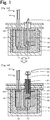
Fig. 1 is an explanatory view schematically illustrating an example of acasting apparatus 10. -
Fig. 2 is an explanatory view illustrating an example of anozzle 30 and acap member 35. -
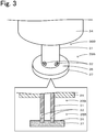
Fig. 3 is an explanatory view illustrating an example of anozzle 30B and acap member 35B. -
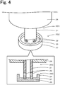
Fig. 4 is an explanatory view illustrating an example of anozzle 30C and acap member 35C. -
Fig. 5 is an explanatory view representing steps of manufacturing a cast product W by vertical upwards continuous casting. -
Fig. 6 is an explanatory view schematically illustrating an example of anothercasting apparatus 10B. -
Fig. 7 is an explanatory view representing experimental results ofExperimental Example1 1 to 5 regarding prevention of slag adhesion and prevention of intrusive mixing of inclusions. -
Fig. 8 represents electron microscopic photos of cast products into which inclusions are intrusively mixed. - An embodiment of the present disclosure will be described below with reference to the drawings.
Fig. 1 is an explanatory view schematically illustrating an example of acasting apparatus 10 according to an embodiment of the present disclosure; specifically,Fig. 1A represents a state in which aninclusion removal unit 15 is mounted, andFig. 1B represents a state in which acasting unit 20 is mounted.Fig. 2 is an explanatory view illustrating an example of anozzle 30 and acap member 35.Fig. 3 is an explanatory view illustrating an example of anothernozzle 30B and anothercap member 35B.Fig. 4 is an explanatory view illustrating an example of anothernozzle 30C and anothercap member 35C. - The
casting apparatus 10 is to carry out vertical upwards continuous casting for casting a cast product by pulling up a molten metal. For example, a pure metal and an alloy can be used as raw materials for the cast product that is to be cast by thecasting apparatus 10. The pure metal may be, for example, oxygen-free copper, tough pitch copper, or deoxidized copper. The alloy may be, for example, a copper alloy or an aluminum alloy. The copper alloy may be, for example, one or more among Cu-Zr, Cu-Sn, Cu-Fe and Cu-Ag alloys and multi-element copper alloys containing some of those elements. Here, the "multi-element copper alloys" are assumed to include alloys containing a third element in addition to the above-mentioned two-element copper alloys. The third element may be, for example, one or more among Ni, Si, Al, etc. The following description is mainly made in connection with the case of using the Cu-Zr alloy. The Cu-Zr alloy may be, for example, a Cu-xZr alloy (where x is not less than 0.5 at% and not more than 5.0 at%) having a hypo-eutectic composition. That alloy can provide a fine dendrite structure and, when subjected to wire drawing, it can further provide a nano-layered structure in an α-Cu phase and a eutectic phase (dual-phase of Cu and a Cu-Zr compound) . Hence an alloy with high strength and high conductivity can be obtained. Details of the Cu-xZr alloy are disclosed in Japanese Patent No.5800300 - The
casting apparatus 10 includes afirst storage section 12, asecond storage section 13, aninclusion removal unit 15, and acasting unit 20. Thecasting apparatus 10 further includes ahousing 11, amaterial supply unit 14, and aheating unit 18. Thefirst storage section 12 and thesecond storage section 13 are defined in thehousing 11. Thehousing 11 has openings through which thematerial supply unit 14 and thecasting unit 20 are inserted. However, the inside of thehousing 11 can be brought into an enclosed state by closing the openings with closure plates or the likes. Thefirst storage section 12 and thesecond storage section 13 are to store amolten metal 19. Thefirst storage section 12 is positioned on the material supply side, and thematerial supply unit 14 is disposed above thefirst storage section 12. Thesecond storage section 13 is positioned on the casting side where themolten metal 19 is pulled up for manufacturing of a cast product, and thecasting unit 20 is disposed above thesecond storage section 13. Thefirst storage section 12 and thesecond storage section 13 are communicated with each other through a flow path formed under both the storage sections. An inert gas supply unit (not illustrated) is connected to thefirst storage section 12 and thesecond storage section 13 such that an inert gas atmosphere can be produced in each of the storage sections. The inert gas may be, for example, rare gas such as Ar, or nitrogen gas. Of those gases, Ar is preferable. - The
material supply unit 14 is a unit for supplying raw materials for themolten metal 19. Thematerial supply unit 14 may feed, for example, wires made of a main component and an additive component of an alloy. When manufacturing a cast product of the Cu-Zr alloy, for example, thematerial supply unit 14 may feed a Cu-wire and a copper pipe, which is made of a raw material containing Zr, to thefirst storage section 12 with adjustment for holding a predetermined Zr content. The raw material to be contained in the copper pipe is preferably a mother alloy of Cu - 50 mass% of Zr. This is because the above mother alloy has a lower melting point (1168K) than that (2125K) of the Zr metal. Thematerial supply unit 14 may sequentially feed, to thefirst storage section 12, a certain amount of the raw material corresponding to an amount of the molten metal that has been cast in thecasting unit 20 and taken out to the outside. - The
inclusion removal unit 15 is to remove inclusions present in themolten metal 19. The inclusions may be, for example, impurity components contained in the raw materials, slag caught into the molten metal, and parts of structural members of thecasting apparatus 10, such as a crucible and refractories, the parts being mixed into themolten metal 19. Theinclusion removal unit 15 may be put into thesecond storage section 13 to perform bubbling in themolten metal 19 with inert gas, thus causing the inclusions in themolten metal 19 to float upwards. Theinclusion removal unit 15 may perform the bubbling with the inert gas in a stationary state, or may perform the bubbling with the inert gas in a state in which vanes are attached to a tip of theinclusion removal unit 15 and are rotated about an axis to stir the inert gas. Theinclusion removal unit 15 includes aporous plug 16 and agas supply pipe 17. Theporous plug 16 is a porous member through which the inert gas fed from thegas supply pipe 17 is discharged in the bubbled form. Theporous plug 16 is preferably made of a porous material with low reactivity to themolten metal 19, and it may be made of ceramic or carbon, for example. A ceramic material is just required to have low reactivity to themolten metal 19 and to withstand the temperature of themolten metal 19. The ceramic material may be, for example, one or more among alumina, zirconia, silica, silicon nitride, etc. In thecasting apparatus 10, casting is carried out after the bubbling by theinclusion removal unit 15. Thus, in thecasting apparatus 10, after causing the inclusions to float upwards by theinclusion removal unit 15, theinclusion removal unit 15 is replaced with thecasting unit 20, followed by casting of a cast product W. Many of the inclusions are lighter than themolten metal 19 and are apt to easily float upwards. However, fine inclusions float upwards at low speed and tend to remain in the molten metal. With the bubbling, because the inclusions are caused to float upwards in a state adhering to bubbles, it is possible to more stably remove the inclusions from the molten metal, and to purify themolten metal 19. A slag layer in which the inclusions are floating is formed in an upper surface of themolten metal 19. - The
heating unit 18 is disposed around thefirst storage section 12 and thesecond storage section 13. Theheating unit 18 is a heater capable of heating the metals as the raw materials to fusible temperature. The heating temperature may be, for example, in the range of not lower than 1500K and not higher than 2000K. - The
casting unit 20 is a unit for quenching themolten metal 19 while pulling up the same, thereby forming a cast product in the form of a wire rod. Thecasting unit 20 is vertically movable such that it is put into thesecond storage section 13 during the casting and is taken out from thesecond storage section 13 after the end of the casting. Thecasting unit 20 includes a die 21, amold 22, a coolingunit 23, acap 24,rollers 25, and anozzle 30. Thedie 21 is disposed inside themold 22 and constitutes a former for the cast product W together with themold 22. Thedie 21 is a cylindrical member made of carbon, for example. The cast product W is formed in a shape in match with an inner diameter shape of thedie 21. Themold 22 is a cylindrical member made of Cu, for example. Thenozzle 30 is detachably attached to a tip of thedie 21. The coolingunit 23 is a unit for cooling themold 22 and is disposed above thenozzle 30. The coolingunit 23 quenches themolten metal 19 taken in through thenozzle 30. Cooling water is supplied to thecooling unit 23 from a circulation unit (not illustrated), and after cooling themold 22, the cooling water is discharged to the circulation unit. Thecap 24 is a member for protecting themold 22 and thenozzle 30 from themolten metal 19. For example, ceramic or carbon may be used as a material of thecap 24. Therollers 25 are disposed above themold 22. Therollers 25 are rotated in a state gripping the cooled cast product W between them, thus pulling up the cast, and are driven by a motor (not illustrated). - The
nozzle 30 is used in the vertical upwards continuous casting for casting the cast product W by pulling up themolten metal 19. Thenozzle 30 is a member that is directly put into themolten metal 19. A material of thenozzle 30 is selected as appropriate depending on the type of themolten metal 19, and it may be, for example, carbon or ceramic such as alumina, zirconia, silica, or silicon nitride. When themolten metal 19 is a copper alloy, thenozzle 30 is preferably made of carbon. Thenozzle 30 is constituted by anozzle body 31 and acap member 35. Thenozzle body 31 is a cylindrical member and is fixedly fitted to a tip of themold 22. An inner space of thenozzle body 31 is communicated with an inner space of thedie 21. Anintake hole 32 through which themolten metal 19 is taken in is formed in a lateral surface of thenozzle body 31. Furthermore, as illustrated inFig. 2 , a lower opening of thenozzle body 31 is closed by thecap member 35. Thus, in thenozzle body 31, themolten metal 19 is taken in from the lateral side. Accordingly, thenozzle body 31 has a structure of being less apt to take in the inclusions, which are lighter than themolten metal 19 and tend to float upwards, than the case of taking in themolten metal 19 from the lower opening. Before the start of the casting, a starting rod 26 (seeFig. 5 ) is inserted into thenozzle body 31. By lifting the startingrod 26, themolten metal 19 is pulled up to the die 21 for casting of the cast product W. - The
cap member 35 is to suppress the inclusions in themolten metal 19 from coming into thenozzle 30. Thecap member 35 includes aflange portion 36 formed on the lower side of theintake hole 32 and projecting beyond thenozzle body 31. Theflange portion 36 may be formed entirely along the outer peripheral side of thenozzle body 31. When thenozzle 30 is put into themolten metal 19, thenozzle 30 passes through a slag layer 29 (seeFig. 1 ) in which the inclusions are floating. Theflange portion 36 may be formed in size that is appropriate to suppress the inclusions from entering theintake hole 32 when thenozzle 30 is put into themolten metal 19. Moreover, theflange portion 36 preferably has a smaller size than a body of thecasting unit 20, such as thecap 24. This is because theflange portion 36 having the smaller size improves operability when it is put into or taken out from thesecond storage section 13. As illustrated inFig. 2 , theflange portion 36 includes a risingwall 38 formed between an outerperipheral edge 37 and thenozzle body 31 and vertically rising in a fashion coming closer to theintake hole 32. With the presence of the risingwall 38, the inclusions can be suppressed from approaching theintake hole 32. The risingwall 38 may be formed entirely along the outer peripheral side of thenozzle body 31. The risingwall 38 may have such a height as covering about a half of theintake hole 32, or covering a region up to a lower end of an opening of theintake hole 32, or covering the whole of theintake hole 32. The height of the risingwall 38 may be appropriately set in consideration of the balance between easiness in taking in themolten metal 19 through theintake hole 32 and the effect of suppressing the inclusions from entering theintake hole 32. In addition, a steppedportion 39 being relatively thick in a central portion (relatively thin in an outer peripheral portion) is formed on the lower surface side of thecap member 35. The steppedportion 39 has the function of, for example, suppressing entrapment of theslag layer 29 when thenozzle 30 is put into themolten metal 19. - The
nozzle 30 has been described above as including thecap member 35 provided with the risingwall 38, but the risingwall 38 may be omitted in another example as illustrated inFig. 3 . Anozzle 30B includes acap member 35B provided with only theflange portion 36. Thenozzle 30B can also suppress the inclusions from approaching theintake hole 32. Furthermore, thenozzle 30 has been described above as including thecap member 35 provided with the risingwall 38 between thenozzle body 31 and the outerperipheral edge 37, but anouter edge wall 34 may be formed, as illustrated inFig. 4 , at the outerperipheral edge 37 of theflange portion 36 in still another example. Anozzle 30C includes acap member 35C in which theouter edge wall 34 vertically rising in a fashion coming closer to theintake hole 32 is formed at the outerperipheral edge 37. The presence of theouter edge wall 34 can further suppress the inclusions from approaching theintake hole 32. Theouter edge wall 34 may be formed to rise entirely along the outer peripheral side of thenozzle body 31. A height of theouter edge wall 34 may be appropriately set as in the case of the risingwall 38. Thenozzle 30C can also reliably suppress the inclusions from approaching theintake hole 32. Thenozzle 30 may be modified such that the steppedportion 39 is not formed, or that the steppedportion 39 is formed in thenozzles nozzle intake hole 32 and in which theflange portion 36 is not formed. Furthermore, thenozzle intake hole 32 and in which theouter edge wall 34 or the risingwall 38 is not formed. Theouter edge wall 34 may be further formed at the outerperipheral edge 37 in thenozzle 30. Although the cap member is a separate member in thenozzles nozzle body 31 may be integrally formed with any of thecap members - A cast product manufacturing method of carrying out the vertical upwards continuous casting for casing the cast product W by pulling up the
molten metal 19 will be described below. The cast product manufacturing method is described on an assumption that the method is implemented using thecasting apparatus 10. The cast product manufacturing method may include, for example, (1) heating step, (2) inclusion removal step, and (3) casting step.Fig. 5 is an explanatory view illustrating steps of manufacturing the cast product W by the vertical upwards continuous casting.Fig. 5A is an explanatory view representing the inclusion removal step,Fig. 5B is an explanatory view representing a state in which thenozzle 30 is put into the molten metal, andFig. 5C is an explanatory view representing a state at the start of the casting. - In this step, a process of supplying raw materials into the
first storage section 12 and thesecond storage section 13, heating and dissolving the raw materials, and preparing the molten metal is performed. The above-described examples of the alloy and the pure metal can be used as the raw materials. The heating temperature can be set as appropriate depending on the raw materials. In the case of using the Cu-Zr alloy having the hypo-eutectic composition, the heating temperature may be set to 1573K or higher, for example. - In this step, a process of performing bubbling in the
molten metal 19 with inert gas and causing the inclusions in the molten metal to float upwards (seeFig. 5A ) is performed. With this process, the molten metal can be purified. Theinclusion removal unit 15 may be put into thesecond storage section 13 after the heating step. A processing time of this step may be set as appropriate depending on the type and amount of themolten metal 19. An amount of gas to be supplied may also be set as appropriate set depending on the type and amount of themolten metal 19. The inert gas used for the bubbling may be, for example, rare gas such as Ar, or nitrogen gas. Of those gases, Ar is preferable. - In this step, a process of moving the
nozzle 30 mounted to thecasting unit 20 downwards to be put into themolten metal 19, taking in the molten metal through thenozzle 30, and casting the cast product W is performed. In this step, a process of cooling themolten metal 19, which has been pulled up through thenozzle 30, by the coolingunit 23 disposed above the nozzle 30 (i.e., a quenching process) is further performed. When thenozzle 30 is put into themolten metal 19, the startingrod 26 is in a state inserted through thedie 21 and thenozzle body 31. When putting thenozzle 30 into themolten metal 19 in this process, thenozzle 30 passes through theslag layer 29. However, since thecap member 35 is disposed at the lower end of thenozzle 30, the inclusions can be reliably suppressed with the presence of theflange portion 36 from approaching the intake hole 32 (Fig. 5B ). Furthermore, since theintake hole 32 is formed in the lateral surface of thenozzle body 31, the inclusions are harder to approach theintake hole 32. When the startingrod 26 is lifted by rotation of therollers 25, themolten metal 19 is also pulled up together with the startingrod 26 and is quenched by the coolingunit 23, whereby the cast product W is cast (Fig. 5C ). On that occasion, the inclusions present in themolten metal 19 may float toward theslag layer 29 in some cases. However, since theintake hole 32 is formed in the lateral surface of thenozzle body 31 and theflange portion 36 is present on the lower side of theintake hole 32, the inclusions are harder to come into thenozzle 30. - In the
casting apparatus 10 described above, thenozzle 30 includes theintake hole 32 formed on the lateral side and theflange portion 36 formed on the lower side of theintake hole 32 and projecting beyond the nozzle body. Therefore, when thenozzle 30 is put into themolten metal 19, the inclusions can be prevented from approaching theintake hole 32. Furthermore, even when the inclusions float upwards from below during the casting, thenozzle 30 can take in the molten metal from the lateral side while preventing the inclusions from approaching the intake hole with the presence of theflange portion 36 formed in the projected shape. As a result, thecasting apparatus 10 can reliably suppress the inclusions from being intrusively mixed into the cast product in the vertical upwards continuous casting. - It is needless to say that the present disclosure is not limited to the above embodiment and it can be variously implemented in various forms insofar as falling within the technical scope of the present disclosure.
- For instance, while, in the above embodiment, the
casting apparatus 10 is described as causing the inclusions to float upwards by theinclusion removal unit 15, then replacing theinclusion removal unit 15 with thecasting unit 20, and carrying out casting of the copper alloy, the present disclosure is not limited to that case.Fig. 6 is an explanatory view schematically illustrating an example of anothercasting apparatus 10B. As illustrated inFig. 6 , theinclusion removal unit 15 may be permanently disposed in the molten metal, and the cast product W may be cast by thecasting unit 20 after causing the inclusions to float upwards by the permanentinclusion removal unit 15. The above-describedcasting apparatus 10B can also reliably suppress the inclusions from being intrusively mixed into the cast product in vertical upwards continuous casting. - While the above embodiment has been described in connection with the
casting apparatus 10, the present disclosure may be implemented as thenozzle 30. Thenozzle 30 can also provide similar advantageous effects to those obtained with thecasting apparatus 10. - Examples of actually fabricating the
casting apparatus 10 and thenozzle 30 will be described below as Experimental Examples. The above-describedcasting apparatus 10 was fabricated and degrees of intrusive mixing of inclusions into cast products were studied while the shape of the nozzle and the shape of the cap member were changed. Experimental Examples 3 to 5 and 7 correspond to Examples, and Experimental Examples 1, 2 and 6 correspond to Comparative Examples. - The nozzle body was formed as a cylindrical member not having the intake hole formed in the lateral surface, and the cap member was given as a plug plugged into an opening of the cylindrical member (see
Fig. 7 ). The starting rod was inserted in the nozzle body before the start of casting. At the start of the casting, the cap member was pushed out to fall by the staring rod. Then, the starting rod was lifted and a cast product was obtained. - The nozzle body was formed as a cylindrical member not having the intake hole formed in the lateral surface, and the cap member was given as a lid closing an opening of the cylindrical member (see
Fig. 7 ). The starting rod was inserted in the nozzle body before the start of casting. At the start of the casting, the cap member was pushed off to fall by the staring rod. Then, the starting rod was lifted and a cast product was obtained. - The nozzle body was formed as a cylindrical member having the intake hole formed in the lateral surface, and a lower opening of the cylindrical member was closed by the cap member including the flange portion projecting beyond the nozzle body on the outer peripheral side (see
Figs. 3 and6 ). The starting rod was inserted in the nozzle body before the start of casting. At the start of the casting, the cap member was kept attached to the nozzle body. Then, the starting rod was lifted and a cast product was obtained. It is to be noted that a photo inFig. 7 represents the nozzle taken out after the casting and including slag adhered thereto when the nozzle was taken out. - The nozzle body was formed as a cylindrical member having the intake hole formed in the lateral surface, and a lower opening of the cylindrical member was closed by the cap member having the flange portion provided with the outer edge wall formed at the outer peripheral edge of the flange portion (see
Figs. 4 and6 ). The starting rod was inserted in the nozzle body before the start of casting. At the start of the casting, the cap member was kept attached to the nozzle body. Then, the starting rod was lifted and a cast product was obtained. - The nozzle body was formed as a cylindrical member having the intake hole formed in the lateral surface, and a lower opening of the cylindrical member was closed by the cap member having the flange portion provided with the rising wall formed between the outer peripheral edge of the flange portion and the nozzle body (see
Figs. 2 and6 ). The starting rod was inserted in the nozzle body before the start of casting. At the start of the casting, the cap member was kept attached to the nozzle body. Then, the starting rod was lifted and a cast product was obtained. - A vertical upwards continuous casting process was performed using the nozzles in Experimental Examples 1 to 5. The composition of the raw materials was set as a Cu-5at%Zr alloy, and a copper wire and a steel pipe containing a Cu-50mass%Zr mother alloy were supplied from the material supply unit. A molten metal was prepared in the state in which the first storage section and the second storage section were heated to 1573K by the heating unit and Ar gas was introduced for suppression of oxidation. In the continuous casting, the die with the inner diameter of 14 mm was used and an operation of pulling up the cast product by servo-driven pinch rollers was intermittently carried out to perform the continuous casting under the condition of an average casting speed being 600 mm/min. Regarding the prevention of slag adhesion at the time of putting the nozzle into the molten metal, a very small amount of the adhering slag was evaluated as "AA", a considerably small amount of the adhering slag was evaluated as "A", and a relatively small amount of the adhering slag was evaluated as "B". Furthermore, regarding the prevention of intrusive mixing of the inclusions during the casting, a very small amount of the mixed inclusions was evaluated as "AA", a considerably small amount of the mixed inclusions was evaluated as "A", a relatively small amount of the mixed inclusions was evaluated as "B", and a large amount of the mixed inclusions was evaluated as "D".
-
Fig. 7 is an explanatory view representing experimental results ofExperimental Example1 1 to 5 regarding the prevention of slag adhesion at the time of putting the nozzle into the molten metal and the prevention of intrusive mixing of the inclusions during the casting. As seen fromFig. 7 , in Experimental Examples 1 and 2, the effect of preventing the slag adhesion at the time of putting the nozzle into the molten metal was recognized. However, the inclusions floating upwards from below were taken into the nozzle during the casting, and the inclusions were intrusively mixed into the cast product.Fig. 8 represents electron microscopic photos of cast products into which the inclusions were intrusively mixed. More specifically,Fig. 8A represents the cast product into which alumina was mixed, andFig. 8B represents the cast product into which carbon was mixed. In each of Experimental Examples 1 and 2, there occurred a cut in the cast product due to the intrusive mixing of the inclusions. On the other hand, in Experimental Examples 3 to 5, it was understood that the intrusive mixing of the inclusions during the casting was suppressed and good cast products were obtained. In particular, it was further understood that the more satisfactory result was obtained by using the nozzle of Experimental Example 5. Moreover, in the case of using the Cu-Zr alloy, the following point is estimated. Because a nano-layered structure with high strength and high conductivity is formed, the necessity of preventing the intrusive mixing of the inclusions is high, and the significance of using the nozzles of Experimental Examples 3 to 5 is very high. - Next, the effect of the bubbling in the inclusion removal step was studied. The cast product manufacturing method in which the bubbling with Ar gas was not performed in the above-described casting process evaluation test before starting the vertical upwards continuous casting process using the nozzle of Experimental Example 5 was defined as Experimental Example 6. The cast product manufacturing method (see
Fig. 5 ) in which the bubbling was performed in the above-described casting process evaluation test by supplying Ar gas through a lance pipe (made of porous carbon) before starting the vertical upwards continuous casting process using the nozzle of Experimental Example 5 was defined as Experimental Example 7. Rolling and die wire drawing were performed such that the cast product was shaped into a Cu-Zr wire with a diameter of 80 µm. The results of manufacturing evaluation are listed in Table 1. As seen from Table 1, in Experimental Example 6 in which the bubbling was not performed before the casting step, the number of disconnections was large, i.e., 40, and an average length was 21000 m. In contrast, in Experimental Example 7 in which the bubbling was performed before the casting step, the number of disconnections was 9 and an average length was 95000 m. Thus, a significant effect resulting from combination of the bubbling with the nozzle was confirmed.[Table 1] Experimental Example 6: No Bubbling Experimental Example 7 : Bubbling Whole length Number of disconnections Average length Whole length Number of disconnections Average length Ten thousand m Ten thousand m Ten thousand m Ten thousand m Casting top 13.3 0 13.3 12.8 1 6.4 8.5 2 2.8 10.2 4 2.0 10.7 1 5.3 10.7 0 10.7 10.4 12 0.8 9.0 3 2.3 10.7 6 1.5 11.1 0 11.0 7.1 6 2.5 9.1 1 1.5 11.6 3 2.9 11.0 0 11.0 Casting bottom 9.3 7 1.2 10.9 0 10.9 5.7 3 1.4 10.4 0 10.4 Total 87.3 40 2.1 95.2 9 9.5 - It is needless to say that the present disclosure is not limited to the above embodiment and it can be variously implemented in various forms insofar as falling within the technical scope of the present disclosure.
- The present application claims priority of Japanese Patent Application No.
2017-070975 filed on March 31, 2017 - The present disclosure can be utilized in metal casting. Reference Signs List
- 10, 10B casting apparatus, 11 housing, 12 first storage section, 13 second storage section, 14 material supply unit, 15 inclusion removal unit, 16 porous plug, 17 gas supply pipe, 18 heating unit, 19 molten metal, 20 casting unit, 21 die, 22 mold, 23 cooling unit, 24 cap, 25 roller, 26 starting rod, 29 slag layer, 30, 30B, 30C nozzle, 31 nozzle body, 32 intake hole, 34 outer edge wall, 35, 35B, 35C cap member, 36 flange portion, 37 outer peripheral edge, 38 rising wall, 39 stepped portion.
Claims (10)
- A nozzle put into a molten metal in vertical upwards continuous casting for casting a cast product by pulling up the molten metal, the nozzle comprising:a nozzle body having an intake hole through which the molten metal is taken in and which is formed in a lateral surface of the nozzle body; anda flange portion formed on lower side of the intake hole and projecting beyond the nozzle body.
- The nozzle according to Claim 1, wherein the flange portion is formed entirely along outer peripheral side of the nozzle body.
- The nozzle according to Claim 1 or 2, wherein the flange portion includes an outer edge wall formed at an outer peripheral edge of the flange portion and vertically rising in a fashion coming closer to the intake hole.
- The nozzle according to any one of Claims 1 to 3, wherein the flange portion includes a rising wall formed between an outer peripheral edge of the flange portion and the nozzle body and vertically rising in a fashion coming closer to the intake hole.
- The nozzle according to any one of Claims 1 to 4, wherein the flange portion is a cap member disposed at a tip of the nozzle body.
- The nozzle according to any one of Claims 1 to 5, wherein the nozzle is used for the molten metal of one or more among Cu-Zr, Cu-Sn, Cu-Fe and Cu-Ag alloys and multi-element copper alloys containing some of the above-mentioned elements.
- A casting apparatus that carries out vertical upwards continuous casting for casting a cast product by pulling up a molten metal, the casting apparatus comprising:a storage section storing the molten metal;an inclusion removal unit put into the storage section, performing bubbling in the molten metal with inert gas, and causing inclusions in the molten metal to float upwards;the nozzle according to any one of Claims 1 to 6, the nozzle being put into the storage section and taking in the molten metal; anda cooling unit disposed above the nozzle and quenching the taken-in molten metal.
- A cast product manufacturing method of carrying out vertical upwards continuous casting for casting a cast product by pulling up a molten metal, the cast product manufacturing method comprising:an inclusion removal step of performing bubbling in the molten metal with inert gas and causing the inclusions in the molten metal to float upwards; anda casting step of, after the inclusion removal step, moving the nozzle according to any one of Claims 1 to 6 downwards to be put into the molten metal, taking in the molten metal, and casting the cast product.
- The cast product manufacturing method according to Claim 8, wherein, in the casting step, the molten metal having been pulled up through the nozzle is cooled by a cooling unit disposed above the nozzle.
- The cast product manufacturing method according to any one of Claims 8 and 9, wherein, in the inclusion removal step, the bubbling is performed in the molten metal of one or more among Cu-Zr, Cu-Sn, Cu-Fe and Cu-Ag alloys and multi-element copper alloys containing some of the above-mentioned elements.
Applications Claiming Priority (2)
| Application Number | Priority Date | Filing Date | Title |
|---|---|---|---|
| JP2017070975 | 2017-03-31 | ||
| PCT/JP2018/008849 WO2018180317A1 (en) | 2017-03-31 | 2018-03-07 | Nozzle, casting device, and method for manufacturing cast material |
Publications (2)
| Publication Number | Publication Date |
|---|---|
| EP3603850A1 true EP3603850A1 (en) | 2020-02-05 |
| EP3603850A4 EP3603850A4 (en) | 2020-11-04 |
Family
ID=63675496
Family Applications (1)
| Application Number | Title | Priority Date | Filing Date |
|---|---|---|---|
| EP18778093.7A Withdrawn EP3603850A4 (en) | 2017-03-31 | 2018-03-07 | NOZZLE, CASTING DEVICE AND METHOD FOR MANUFACTURING CAST MATERIAL |
Country Status (6)
| Country | Link |
|---|---|
| US (1) | US11351600B2 (en) |
| EP (1) | EP3603850A4 (en) |
| JP (1) | JP6979454B2 (en) |
| KR (1) | KR102282783B1 (en) |
| CN (1) | CN110461500B (en) |
| WO (1) | WO2018180317A1 (en) |
Family Cites Families (18)
| Publication number | Priority date | Publication date | Assignee | Title |
|---|---|---|---|---|
| US3578064A (en) * | 1968-11-26 | 1971-05-11 | Inland Steel Co | Continuous casting apparatus |
| JPS4940656Y1 (en) * | 1969-12-25 | 1974-11-08 | ||
| JPS58300B2 (en) | 1979-11-21 | 1983-01-06 | 上野 太重郎 | How to make sheep can |
| JPS61262450A (en) * | 1985-05-17 | 1986-11-20 | Kawasaki Steel Corp | Continuous casting method for molten metal |
| US4911226A (en) * | 1987-08-13 | 1990-03-27 | The Standard Oil Company | Method and apparatus for continuously casting strip steel |
| JPH02284751A (en) * | 1989-04-25 | 1990-11-22 | Sumitomo Heavy Ind Ltd | Tundish refining device |
| IT1307538B1 (en) * | 1999-12-27 | 2001-11-06 | Silvana Lastrucci | HOT DRAWING MACHINE |
| JP2004174513A (en) | 2002-11-25 | 2004-06-24 | Nippon Steel Corp | Method for producing continuous cast slab with excellent cleanliness |
| JP4216642B2 (en) * | 2003-05-20 | 2009-01-28 | 新日本製鐵株式会社 | Immersion nozzle and continuous casting method using the same |
| FI123369B (en) * | 2009-05-18 | 2013-03-15 | Upcast Oy | An extrusion die and its use |
| FI124847B (en) * | 2009-11-18 | 2015-02-13 | Upcast Oy | Nozzle for continuous casting, mold part, method for continuous casting and use of a rod, wire or pipe made with a continuous casting nozzle, with a mold part or by a method for continuous casting, as a blank |
| JP5088400B2 (en) * | 2010-06-18 | 2012-12-05 | 住友金属工業株式会社 | Steel continuous casting method |
| JP2014144484A (en) * | 2013-01-30 | 2014-08-14 | Toyota Motor Corp | Hoisting type continuous casting device |
| CN204842961U (en) * | 2015-08-21 | 2015-12-09 | 安徽工业大学 | Get rid of immersion nozzle of inclusion |
| JP6344360B2 (en) | 2015-10-06 | 2018-06-20 | トヨタ自動車株式会社 | Method for controlling powder molding apparatus |
| CN205599902U (en) * | 2016-04-07 | 2016-09-28 | 保定亿嘉特种陶瓷制造有限公司 | Side opening formula stalk |
| CN206047055U (en) * | 2016-09-09 | 2017-03-29 | 浙江万丰奥威汽轮股份有限公司 | A kind of stalk mechanism |
| CN206028681U (en) * | 2016-09-22 | 2017-03-22 | 江西省鹰潭铜产业工程技术研究中心 | But draw casting device on grain refinement |
-
2018
- 2018-03-07 KR KR1020197027943A patent/KR102282783B1/en active Active
- 2018-03-07 WO PCT/JP2018/008849 patent/WO2018180317A1/en not_active Ceased
- 2018-03-07 JP JP2019509125A patent/JP6979454B2/en not_active Expired - Fee Related
- 2018-03-07 EP EP18778093.7A patent/EP3603850A4/en not_active Withdrawn
- 2018-03-07 CN CN201880021172.3A patent/CN110461500B/en not_active Expired - Fee Related
-
2019
- 2019-09-19 US US16/575,880 patent/US11351600B2/en active Active
Also Published As
| Publication number | Publication date |
|---|---|
| CN110461500A (en) | 2019-11-15 |
| US11351600B2 (en) | 2022-06-07 |
| WO2018180317A1 (en) | 2018-10-04 |
| KR102282783B1 (en) | 2021-07-29 |
| EP3603850A4 (en) | 2020-11-04 |
| KR20190121819A (en) | 2019-10-28 |
| CN110461500B (en) | 2021-05-28 |
| JP6979454B2 (en) | 2021-12-15 |
| JPWO2018180317A1 (en) | 2020-02-06 |
| US20200009649A1 (en) | 2020-01-09 |
Similar Documents
| Publication | Publication Date | Title |
|---|---|---|
| KR101450916B1 (en) | Process for manufacturing copper alloy wire rod and copper alloy wire rod | |
| JP4504914B2 (en) | Aluminum ingot manufacturing method, aluminum ingot, and protective gas for manufacturing aluminum ingot | |
| JP5137642B2 (en) | Method for producing copper or copper alloy wire and copper or copper alloy wire | |
| EP3075875A1 (en) | Aluminium alloy for aerosol cans manufactured by the impact extrusion and the process for preparation thereof | |
| CN102686337B (en) | Process for producing copper alloy wire containing active element | |
| CN105358723B (en) | Method for producing aluminum alloy containing lithium | |
| JP4747689B2 (en) | Continuous production method of copper alloy | |
| JPH1192837A (en) | Refinement of copper alloy | |
| US11351600B2 (en) | Nozzle, casting apparatus, and cast product manufacturing method | |
| JP2011012300A (en) | Copper alloy and method for producing copper alloy | |
| US5062614A (en) | Apparatus and method for manufacturing copper-base alloy | |
| US11440086B2 (en) | Method for producing Cu—Ni—Sn alloy and cooler to be used for same | |
| EP0259772B1 (en) | Apparatus and method for manufacturing copper-base alloy | |
| JP6361194B2 (en) | Copper ingot, copper wire, and method for producing copper ingot | |
| KR100304351B1 (en) | Method and device of production with copper alloy a be due to horizontal continuous casting | |
| JP2006156129A (en) | Method for producing copper or copper alloy fine wire | |
| JPH10216905A (en) | Continuous casting method of copper alloy containing active element | |
| JP2018015767A (en) | Method for producing alloy casting | |
| JPH0631398A (en) | Production of active metal-containing copper alloy | |
| CN113613810A (en) | Method for manufacturing steel ingot | |
| CN119710321A (en) | A preparation method of high-purity oxygen-free copper ingot and radio frequency component | |
| UA134397U (en) | CONTINUOUS CASTING OF SMALL METAL WIRE METALS OF ACTIVE METALS | |
| JPH0839197A (en) | Production of co based fine metallic wire |
Legal Events
| Date | Code | Title | Description |
|---|---|---|---|
| STAA | Information on the status of an ep patent application or granted ep patent |
Free format text: STATUS: THE INTERNATIONAL PUBLICATION HAS BEEN MADE |
|
| PUAI | Public reference made under article 153(3) epc to a published international application that has entered the european phase |
Free format text: ORIGINAL CODE: 0009012 |
|
| STAA | Information on the status of an ep patent application or granted ep patent |
Free format text: STATUS: REQUEST FOR EXAMINATION WAS MADE |
|
| 17P | Request for examination filed |
Effective date: 20190919 |
|
| AK | Designated contracting states |
Kind code of ref document: A1 Designated state(s): AL AT BE BG CH CY CZ DE DK EE ES FI FR GB GR HR HU IE IS IT LI LT LU LV MC MK MT NL NO PL PT RO RS SE SI SK SM TR |
|
| AX | Request for extension of the european patent |
Extension state: BA ME |
|
| DAV | Request for validation of the european patent (deleted) | ||
| DAX | Request for extension of the european patent (deleted) | ||
| A4 | Supplementary search report drawn up and despatched |
Effective date: 20201005 |
|
| RIC1 | Information provided on ipc code assigned before grant |
Ipc: B22D 11/14 20060101AFI20200929BHEP Ipc: B22D 11/00 20060101ALI20200929BHEP |
|
| STAA | Information on the status of an ep patent application or granted ep patent |
Free format text: STATUS: EXAMINATION IS IN PROGRESS |
|
| 17Q | First examination report despatched |
Effective date: 20220203 |
|
| STAA | Information on the status of an ep patent application or granted ep patent |
Free format text: STATUS: THE APPLICATION IS DEEMED TO BE WITHDRAWN |
|
| 18D | Application deemed to be withdrawn |
Effective date: 20251001 |