EP3602921B1 - Techniques for communicating synchronization signal block index in a timing synchronization signal - Google Patents
Techniques for communicating synchronization signal block index in a timing synchronization signal Download PDFInfo
- Publication number
- EP3602921B1 EP3602921B1 EP18716407.4A EP18716407A EP3602921B1 EP 3602921 B1 EP3602921 B1 EP 3602921B1 EP 18716407 A EP18716407 A EP 18716407A EP 3602921 B1 EP3602921 B1 EP 3602921B1
- Authority
- EP
- European Patent Office
- Prior art keywords
- block
- tss
- pbch
- examples
- sss
- Prior art date
- Legal status (The legal status is an assumption and is not a legal conclusion. Google has not performed a legal analysis and makes no representation as to the accuracy of the status listed.)
- Active
Links
Images


Classifications
-
- H—ELECTRICITY
- H04—ELECTRIC COMMUNICATION TECHNIQUE
- H04L—TRANSMISSION OF DIGITAL INFORMATION, e.g. TELEGRAPHIC COMMUNICATION
- H04L27/00—Modulated-carrier systems
- H04L27/26—Systems using multi-frequency codes
- H04L27/2601—Multicarrier modulation systems
- H04L27/2647—Arrangements specific to the receiver only
- H04L27/2655—Synchronisation arrangements
- H04L27/2662—Symbol synchronisation
-
- H—ELECTRICITY
- H04—ELECTRIC COMMUNICATION TECHNIQUE
- H04W—WIRELESS COMMUNICATION NETWORKS
- H04W72/00—Local resource management
- H04W72/20—Control channels or signalling for resource management
- H04W72/23—Control channels or signalling for resource management in the downlink direction of a wireless link, i.e. towards a terminal
-
- H—ELECTRICITY
- H04—ELECTRIC COMMUNICATION TECHNIQUE
- H04J—MULTIPLEX COMMUNICATION
- H04J11/00—Orthogonal multiplex systems, e.g. using WALSH codes
- H04J11/0069—Cell search, i.e. determining cell identity [cell-ID]
- H04J11/0073—Acquisition of primary synchronisation channel, e.g. detection of cell-ID within cell-ID group
-
- H—ELECTRICITY
- H04—ELECTRIC COMMUNICATION TECHNIQUE
- H04J—MULTIPLEX COMMUNICATION
- H04J11/00—Orthogonal multiplex systems, e.g. using WALSH codes
- H04J11/0069—Cell search, i.e. determining cell identity [cell-ID]
- H04J11/0076—Acquisition of secondary synchronisation channel, e.g. detection of cell-ID group
-
- H—ELECTRICITY
- H04—ELECTRIC COMMUNICATION TECHNIQUE
- H04L—TRANSMISSION OF DIGITAL INFORMATION, e.g. TELEGRAPHIC COMMUNICATION
- H04L27/00—Modulated-carrier systems
- H04L27/26—Systems using multi-frequency codes
- H04L27/2601—Multicarrier modulation systems
- H04L27/2647—Arrangements specific to the receiver only
- H04L27/2655—Synchronisation arrangements
- H04L27/2656—Frame synchronisation, e.g. packet synchronisation, time division duplex [TDD] switching point detection or subframe synchronisation
-
- H—ELECTRICITY
- H04—ELECTRIC COMMUNICATION TECHNIQUE
- H04L—TRANSMISSION OF DIGITAL INFORMATION, e.g. TELEGRAPHIC COMMUNICATION
- H04L27/00—Modulated-carrier systems
- H04L27/26—Systems using multi-frequency codes
- H04L27/2601—Multicarrier modulation systems
- H04L27/2647—Arrangements specific to the receiver only
- H04L27/2655—Synchronisation arrangements
- H04L27/2666—Acquisition of further OFDM parameters, e.g. bandwidth, subcarrier spacing, or guard interval length
-
- H—ELECTRICITY
- H04—ELECTRIC COMMUNICATION TECHNIQUE
- H04L—TRANSMISSION OF DIGITAL INFORMATION, e.g. TELEGRAPHIC COMMUNICATION
- H04L27/00—Modulated-carrier systems
- H04L27/26—Systems using multi-frequency codes
- H04L27/2601—Multicarrier modulation systems
- H04L27/2647—Arrangements specific to the receiver only
- H04L27/2655—Synchronisation arrangements
- H04L27/2668—Details of algorithms
- H04L27/2673—Details of algorithms characterised by synchronisation parameters
- H04L27/2675—Pilot or known symbols
-
- H—ELECTRICITY
- H04—ELECTRIC COMMUNICATION TECHNIQUE
- H04L—TRANSMISSION OF DIGITAL INFORMATION, e.g. TELEGRAPHIC COMMUNICATION
- H04L5/00—Arrangements affording multiple use of the transmission path
- H04L5/003—Arrangements for allocating sub-channels of the transmission path
- H04L5/0048—Allocation of pilot signals, i.e. of signals known to the receiver
- H04L5/005—Allocation of pilot signals, i.e. of signals known to the receiver of common pilots, i.e. pilots destined for multiple users or terminals
-
- H—ELECTRICITY
- H04—ELECTRIC COMMUNICATION TECHNIQUE
- H04L—TRANSMISSION OF DIGITAL INFORMATION, e.g. TELEGRAPHIC COMMUNICATION
- H04L5/00—Arrangements affording multiple use of the transmission path
- H04L5/003—Arrangements for allocating sub-channels of the transmission path
- H04L5/0048—Allocation of pilot signals, i.e. of signals known to the receiver
- H04L5/0051—Allocation of pilot signals, i.e. of signals known to the receiver of dedicated pilots, i.e. pilots destined for a single user or terminal
-
- H—ELECTRICITY
- H04—ELECTRIC COMMUNICATION TECHNIQUE
- H04L—TRANSMISSION OF DIGITAL INFORMATION, e.g. TELEGRAPHIC COMMUNICATION
- H04L5/00—Arrangements affording multiple use of the transmission path
- H04L5/003—Arrangements for allocating sub-channels of the transmission path
- H04L5/0053—Allocation of signalling, i.e. of overhead other than pilot signals
-
- H—ELECTRICITY
- H04—ELECTRIC COMMUNICATION TECHNIQUE
- H04W—WIRELESS COMMUNICATION NETWORKS
- H04W56/00—Synchronisation arrangements
- H04W56/001—Synchronization between nodes
- H04W56/0015—Synchronization between nodes one node acting as a reference for the others
-
- H—ELECTRICITY
- H04—ELECTRIC COMMUNICATION TECHNIQUE
- H04W—WIRELESS COMMUNICATION NETWORKS
- H04W72/00—Local resource management
- H04W72/04—Wireless resource allocation
- H04W72/044—Wireless resource allocation based on the type of the allocated resource
- H04W72/0453—Resources in frequency domain, e.g. a carrier in FDMA
Definitions
- the present disclosure for example, relates to wireless communication systems, and more particularly to techniques for communicating a synchronization signal (SS) block index in a timing synchronization signal (TSS).
- SS synchronization signal
- TSS timing synchronization signal
- Wireless communication systems are widely deployed to provide various types of communication content such as voice, video, packet data, messaging, broadcast, and so on.
- These systems may be multiple-access systems capable of supporting communication with multiple users by sharing the available system resources (e.g., time, frequency, and power).
- Examples of such multiple-access systems include code-division multiple access (CDMA) systems, time-division multiple access (TDMA) systems, frequency-division multiple access (FDMA) systems, and orthogonal frequency-division multiple access (OFDMA) systems.
- CDMA code-division multiple access
- TDMA time-division multiple access
- FDMA frequency-division multiple access
- OFDMA orthogonal frequency-division multiple access
- a wireless multiple-access communication system may include a number of base stations, each simultaneously supporting communication for multiple communication devices, otherwise known as user equipments (UEs).
- UEs user equipments
- LTE Long-Term Evolution
- LTE-A LTE-Advanced
- a set of one or more base stations may define an eNodeB (eNB).
- eNB eNodeB
- NR new radio
- mmW millimeter wave
- 5G new radio
- a base station may take the form of a smart radio head (or radio head (RH)) or access node controller (ANC), with a set of smart radio heads in communication with an ANC defining a gNodeB (gNB).
- RH radio head
- ANC access node controller
- a base station may communicate with a set of UEs) on downlink channels (e.g., for transmissions from a base station to a UE and uplink channels (e.g., for transmissions from a UE to a base station).
- Wireless devices that operate in mmW frequency ranges may be associated with increased signal attenuation (e.g., path loss), which may be influenced by various factors, such as temperature, barometric pressure, diffraction, etc.
- signal processing techniques such as beamforming, may be used to coherently combine energy and overcome the path losses at these frequencies.
- a base station may transmit signals on a broadcast channel by repetitively transmitting the signals while changing the beam on which the signals are transmitted (e.g., the base station may transmit the signals on each of a plurality of beams while performing a beam sweep).
- a base station may repetitively transmit a group of signals defining a SS block.
- SS burst composition is described in 3GPP R1-1702585
- SS numerology is described in 3GPP R1-1701056
- NR-PBCH design can be found in 3GPP R1-1703094.
- the signals transmitted within the SS block may include a primary synchronization signal (PSS), a secondary synchronization signal (SSS), and/or a physical broadcast channel (PBCH).
- PSS primary synchronization signal
- SSS secondary synchronization signal
- PBCH physical broadcast channel
- the described techniques relate to improved methods, systems, and devices, or apparatuses that support communicating a synchronization signal (SS) block index in a timing synchronization signal (TSS).
- SS synchronization signal
- TSS timing synchronization signal
- the described techniques relate to a base station transmitting a set of SS blocks each conveying a TSS that includes a SS block index, and a user equipment (UE) may identify and use the SS block index to determine the timing of the TSS with respect to a broadcast channel transmission time interval (BCH TTI).
- BCH TTI broadcast channel transmission time interval
- the UE may use the timing of the TTI to reduce the amount of time required to acquire and synchronize with the base station.
- a wireless communication system may utilize directional or beamformed transmissions (e.g., beams) for communication.
- a base station may transmit signals on multiple beams associated with different directions.
- the base station may engage in beam sweeping over a portion (or all) of the possible beams for transmitting messages or signals intended for UEs distributed throughout a coverage area of the base station.
- a base station may transmit multiple instances of a SS block, on different beams, during a periodic BCH TTI.
- a base station may transmit multiple instances of a SS block on a same beam, or in an omnidirectional manner.
- a UE that receives one of the SS blocks may acquire a network associated with the base station. However, before or while acquiring the network, the UE may determine the timing of one or more SS blocks that it receives. In some cases, the timing of a SS block may be determined based at least in part on a SS block index that conveys the timing of the SS block within a sequence of SS blocks.
- a TSS may be referred to as a tertiary synchronization signal or extended synchronization signal since it augments primary and secondary synchronization signals (PSS and SSS) and may enable more efficient synchronization between the UE and the base station.
- a TSS may be transmitted alongside other synchronization signals ⁇ such as PSS and SSS ⁇ that convey time synchronization at different granularity (e.g., OFDM symbol timing but not necessarily the OFDM symbol index or the SS block index).
- a base station may periodically transmit 40 SS blocks. All or many of these SS blocks may contain identically transmitted signals such as a PSS/SSS and a PBCH. Therefore, these blocks may not be distinguishable.
- a TSS can also be transmitted in every SS block but may change from block to block to convey the SS block index.
- an SS block may carry one or more synchronization signals (such as PSS, SSS, and/or TSS). If the base station coherently transmits all signals within an SS block (e.g., from the same antenna port), then the UE can assume that the synchronization signals are quasi-collocated and therefore may have consistent signal properties, such as the delay spread, Doppler spread, Doppler shift, etc. Based on this assumption, the UE may be able to synchronize with the base station more quickly by using, for example, SSS as a reference for TSS, which in turn serves as reference for a PBCH. The UE may then use TSS and SSS together to demodulate the PBCH.
- synchronization signals such as PSS, SSS, and/or TSS.
- the UE determine a signal to noise ratio (SNR) and/or a signal to noise plus interference ratio (SINR) for the TSS, the SSS, or both, transmitted via a wireless channel, and use the determined SNR and/or SINR for demodulating the PBCH.
- the UE may use the TSS, the SSS, or both, to generate a channel estimate (e.g., estimate of a phase shift caused to the TSS, the SSS, or both, by transmission via a wireless channel), and use the channel estimate for demodulating the PBCH.
- a channel estimate e.g., estimate of a phase shift caused to the TSS, the SSS, or both, by transmission via a wireless channel
- TSS may be used instead to convey SS block index.
- the changes in PBCH can be used to verify the SS block index determined using the TSS.
- FIG. 1 shows an example of a wireless communication system 100, in accordance with various aspects of the present disclosure.
- the wireless communication system 100 includes base stations 105, UEs 115, and a core network 130.
- the wireless communication system 100 may be a Long Term Evolution (LTE), LTE-Advanced (LTE-A) network, or a New Radio (NR) network.
- LTE Long Term Evolution
- LTE-A LTE-Advanced
- NR New Radio
- wireless communication system 100 may support enhanced broadband communications, ultra-reliable (i.e., mission critical) communications, low latency communications, and communications with low-cost and low-complexity devices.
- ultra-reliable i.e., mission critical
- Base stations 105 may wirelessly communicate with UEs 115 via one or more base station antennas. Each base station 105 may provide communication coverage for a respective geographic coverage area 110.
- Communication links 125 shown in wireless communication system 100 may include uplink (UL) transmissions from a UE 115 to a base station 105, or downlink (DL) transmissions, from a base station 105 to a UE 115.
- Control information and data may be multiplexed on an uplink channel or downlink according to various techniques. Control information and data may be multiplexed on a downlink channel, for example, using time division multiplexing (TDM) techniques, frequency division multiplexing (FDM) techniques, or hybrid TDM-FDM techniques.
- TDM time division multiplexing
- FDM frequency division multiplexing
- hybrid TDM-FDM techniques hybrid TDM-FDM techniques.
- the control information transmitted during a TTI of a downlink channel may be distributed between different control regions in a cascaded manner (e.g., between a common
- UEs 115 may be dispersed throughout the wireless communication system 100, and each UE 115 may be stationary or mobile.
- a UE 115 may also be referred to as a mobile station, a subscriber station, a mobile unit, a subscriber unit, a wireless unit, a remote unit, a mobile device, a wireless device, a wireless communications device, a remote device, a mobile subscriber station, an access terminal, a mobile terminal, a wireless terminal, a remote terminal, a handset, a user agent, a mobile client, a client, or some other suitable terminology.
- a UE 115 may also be a cellular phone, a personal digital assistant (PDA), a wireless modem, a wireless communication device, a handheld device, a tablet computer, a laptop computer, a cordless phone, a personal electronic device, a handheld device, a personal computer, a wireless local loop (WLL) station, an Internet of things (IoT) device, an Internet of Everything (IoE) device, a machine type communication (MTC) device, an appliance, an automobile, or the like.
- PDA personal digital assistant
- WLL wireless local loop
- IoT Internet of things
- IoE Internet of Everything
- MTC machine type communication
- a UE 115 may also be able to communicate directly with other UEs (e.g., using a peer-to-peer (P2P) or device-to-device (D2D) protocol).
- P2P peer-to-peer
- D2D device-to-device
- One or more of a group of UEs 115 utilizing D2D communications may be within the geographic coverage area 110 of a cell. Other UEs 115 in such a group may be outside the geographic coverage area 110 of a cell, or otherwise unable to receive transmissions from a base station 105.
- groups of UEs 115 communicating via D2D communications may utilize a one-to-many (1:M) system in which each UE 115 transmits to every other UE 115 in the group.
- a base station 105 facilitates the scheduling of resources for D2D communications.
- D2D communications are carried out independent of a base station 105.
- Some UEs 115 may be low cost or low complexity devices, and may provide for automated communication between machines, i.e., Machine-to-Machine (M2M) communication.
- M2M or MTC may refer to data communication technologies that allow devices to communicate with one another or a base station without human intervention.
- M2M or MTC may refer to communications from devices that integrate sensors or meters to measure or capture information and relay that information to a central server or application program that can make use of the information or present the information to humans interacting with the program or application.
- Some UEs 115 may be designed to collect information or enable automated behavior of machines. Examples of applications for MTC devices include smart metering, inventory monitoring, water level monitoring, equipment monitoring, healthcare monitoring, wildlife monitoring, weather and geological event monitoring, fleet management and tracking, remote security sensing, physical access control, and transaction-based business charging.
- an MTC device may operate using half-duplex (one-way) communications at a reduced peak rate. MTC devices may also be configured to enter a power saving "deep sleep" mode when not engaging in active communications. In some cases, MTC or IoT devices may be designed to support mission critical functions and wireless communication system may be configured to provide ultra-reliable communications for these functions.
- Base stations 105 may communicate with the core network 130 and with one another. For example, base stations 105 may interface with the core network 130 through backhaul links 132 (e.g., S1, etc.). Base stations 105 may communicate with one another over backhaul links 134 (e.g., X2, etc.) either directly or indirectly (e.g., through core network 130). Base stations 105 may perform radio configuration and scheduling for communication with UEs 115, or may operate under the control of a base station controller (not shown). In some examples, base stations 105 may be macro cells, small cells, hot spots, or the like. Base stations 105 may also be referred to as eNodeBs (eNBs) or gNodeBs (gNBs).
- eNBs eNodeBs
- gNBs gNodeBs
- a base station 105 may be connected by an S1 interface to the core network 130.
- the core network may be an evolved packet core (EPC), which may include at least one mobility management entity (MME), at least one serving gateway (S-GW), and at least one Packet Data Network (PDN) gateway (P-GW).
- EPC evolved packet core
- MME mobility management entity
- S-GW serving gateway
- P-GW Packet Data Network gateway
- IP Packet Data Network gateway
- All user Internet Protocol (IP) packets may be transferred through the S-GW, which itself may be connected to the P-GW.
- the P-GW may provide IP address allocation as well as other functions.
- the P-GW may be connected to the network operators IP services.
- the operators IP services may include the Internet, the Intranet, an IP Multimedia Subsystem (IMS), and a Packet-Switched (PS).
- IMS IP Multimedia Subsystem
- PS Packet-Switched
- the core network 130 may provide user authentication, access authorization, tracking, IP connectivity, and other access, routing, or mobility functions.
- the network devices such as base station 105 may include subcomponents such as an access network entity, which may be an example of an access node controller (ANC).
- ANC access node controller
- Each access network entity may communicate with a number of UEs 115 through a number of other access network transmission entities, each of which may be an example of a smart radio head, or a transmission/reception point (TRP).
- TRP transmission/reception point
- various functions of each access network entity or base station 105 may be distributed across various network devices (e.g., radio heads and access network controllers) or consolidated into a single network device (e.g., a base station 105).
- a UE 115 may perform an initial access (acquisition) procedure with a base station 105, synchronize with a base station 105, or measure signals transmitted by a base station 105.
- the UE 115 may search a wireless spectrum for a SS block transmitted by the base station 105.
- the SS block may include information usable by the UE 115 to synchronize the UE 115 with the base station 105, so that the UE 115 may communicate with the base station 105 (or over a network to which the base station 105 provides access).
- the UE 115 may initiate a random access procedure with the base station 105 by transmitting a random access preamble to the base station 105.
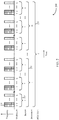
- FIG. 2 shows an example timeline 200 of SS blocks 205 within a periodic BCH TTI, in accordance with various aspects of the present disclosure.
- the SS blocks 205 may be transmitted by a base station, which base station may be an example of aspects of one or more of the base stations 105 described with reference to FIG. 1 .
- a UE may receive one or more of the SS blocks 205.
- the UE may be an example of aspects of one or more of the UEs 115 described with reference to FIG. 1 .
- the SS blocks 205 may include a plurality of SS blocks 205 transmitted in succession during a SS block burst 210.
- a SS block burst 210 may include L SS blocks 205.
- the SS blocks 205 within a SS block burst 210 may be transmitted on different beams using a beam sweep.
- the SS blocks 205 within a SS block burst 210 may be transmitted on a same beam, or in an omnidirectional manner.
- a SS block 205 may include a TSS and one or more of a PSS, a SSS, or a PBCH.
- the PBCH may carry a master information block (MIB) and the TSS.
- MIB master information block
- the TSS may convey a SS block index or other timing information.
- the TSS may be a set of coded bits to be sent using modulation symbols, where the coded bits encode at least an SS block index.
- the coded bits may include one or more other parameters of a beam sweep configuration of a base station 105.
- the one or more parameters may include a periodicity of burst set, a number of beams in the burst set, or the like.
- the burst set may be defined as the set of beams transmitted periodically and carrying SS blocks 205 in a coverage are of base station 105.
- a SS block index may indicate a timing of a TSS (or SS block 205) within a sequence of SS blocks 205 (e.g., a timing of a TSS (or SS block 205) within a SS block burst 210).
- a SS block index may thus also indicate a timing of a SS block 205 within a SS block burst-set 215 and within a BCH TTI 220 (although in some cases, other timing information may need to be combined with the timing indicated by a SS block index to fully determine a timing of a SS block 205 within a SS block burst-set 215 or BCH TTI 220).
- a SS block index may also indicate a beam on which a SS block 205 is transmitted.
- a SS block index may be encoded in a waveform signature of a TSS (e.g., the SS block index may be sequence-based) or included in at least one modulation symbol in the TSS (e.g., the SS block index may be message-based).
- the SSS of a SS block 205 may be based at least in part on a physical cell identity (PCI) of the base station that transmitted the SS block 205.
- PCI physical cell identity
- a plurality of SS blocks bursts 210 may be transmitted within a SS block burst-set 215.
- the SS block bursts 210 in a SS block burst-set 215 may be associated with different PBCH redundancy versions (RVs).
- a SS block burst-set 215 may include n SS block bursts 210.
- the SS block bursts 210 within a SS block burst-set 215 may be separated in time.
- a plurality of SS block burst-sets 215 may be transmitted within the BCH TTI 220.
- a BCH TTI is defined to include any time interval in which a plurality of SS blocks are transmitted with the same system information, regardless of whether the SS blocks are allocated to SS block bursts 210 or SS block burst-sets 215.
- the SS block burst-sets 215 in a BCH TTI 220 may be associated with different SSSs.
- a BCH TTI 220 may include m SS block burst-sets 215.
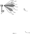
- FIG. 3 shows an example of a mmW wireless communication system 300, in accordance with various aspects of the present disclosure.
- the mmW wireless communication system 300 may include a base station 305 and a UE 315, which may be examples of aspects of one or more of the base stations 105 or UEs 115 described with reference to FIG. 1 .
- the base station 305 and UE 315 may communicate with one another on one or more beams (i.e., directional beams).
- the base station 305 may transmit signals on a plurality of beams 320 (e.g., on different directional beams 320, including, for example, a first beam 320-a, a second beam 320-b, a third beam 320-c, a fourth beam 320-d, a fifth beam 320-e, and a sixth beam 320-f).
- the base station 305 may transmit on more or fewer beams 320.
- the base station 305 may transmit a SS block on each of the beams 320, and the UE 315 may receive the SS block on one of the beams 320.
- the UE 315 may determine the timing of the SS block, and a beam 320 on which the SS block is received, to acquire a network to which the base station 305 provides access.
- the UE 315 may determine the timing of the SS block and/or identify the beam 320 on which the SS block is received based at least in part on a SS block index conveyed by a TSS included in the SS block.
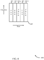
- FIGs. 4 ⁇ 7 show examples of time-frequency plots for SS blocks having various configurations.
- FIG. 4 shows an example time-frequency plot 400 of a SS block 405, in accordance with various aspects of the present disclosure.
- the SS block 405 includes a PSS 410, SSS 415, first portion of a PBCH 420-a, TSS 425, and second portion of the PBCH 420-b that are time division multiplexed on a same set of one or more frequency subcarriers and transmitted in the order shown in FIG. 4 .
- FIG. 5 shows an example time-frequency plot 500 of a SS block 505, in accordance with various aspects of the present disclosure.
- the SS block 505 includes a PSS 520, SSS 525, and second portion of a PBCH 510-b that are time division multiplexed on a same set of one or more frequency subcarriers and transmitted in the order shown in FIG. 5 .
- the SS block 505 may also include a first portion of the PBCH 510-a and a TSS 515 that are frequency division multiplexed and transmitted before the PSS 520.
- the TSS 515 is therefore transmitted on a first set of one or more frequency subcarriers that overlaps a second set of frequency subcarriers on which the PSS 520, SSS 525, and PBCH 510 are transmitted.
- FIG. 6 shows an example time-frequency plot 600 of a SS block 605, in accordance with various aspects of the present disclosure.
- the SS block 605 includes a PSS 610, first portion of a PBCH 615-a, SSS 620, TSS 625, and second portion of the PBCH 615-b that are time division multiplexed and transmitted in the order shown in FIG. 6 .
- FIG. 7 shows an example time-frequency plot 700 of a SS block 705, in accordance with various aspects of the present disclosure.
- the SS block 705 includes a PSS 710 and SSS 715 that are time division multiplexed and transmitted over a range of frequency subcarriers (or resource blocks) in the order shown in FIG. 7 .
- the SS block 705 may also include a TSS transmitted on a first set of frequency subcarriers that is interleaved with a second set of frequency subcarriers on which the PBCH is transmitted.
- the interleaved frequency subcarriers 720-a and 720-b on which the TSS and PBCH are transmitted may be frequency division multiplexed with the PSS 710 and SSS 715, and in some cases, the interleaved frequency subcarriers 720-a and 720-b on which the TSS and PBCH are transmitted may include frequency subcarriers on either end of the range of frequency subcarriers over which the PSS 710 and SSS 715 are transmitted.
- the TSS described with reference to any of FIGs. 2 and 4 ⁇ 7 may be based at least in part on a timing of the TSS within a BCH TTI and/or based at least in part on a SS block index associated with a SS block in which the TSS is transmitted.
- the SS block index may indicate the timing of the TSS within a BCH TTI (e.g., the SS block index may partially or fully indicate the timing of the TSS within the BCH TTI).
- the TSS may be transmitted (used) as a DMRS for a PBCH, on at least one port used to transmit the TSS and the PBCH.
- the TSS may be coherently transmitted from the same port used to transmit a transmission via the PBCH.
- the SSS may also be transmitted (used) as a DMRS for the PBCH, on at least one port used to transmit the SSS and the PBCH.
- the SSS may be coherently transmitted from the same port used to transmit a transmission via the PBCH.
- the TSS and PBCH may be transmitted within a same SS block. In other examples, the TSS and PBCH may not be transmitted in a same SS block.
- the SSS described with reference to any of FIGs. 2 , 4 , and 6 may be transmitted (used) as a DMRS for a TSS, on at least one port used to transmit the SSS and the TSS.
- the TSS may be transmitted/detected coherently with the SSS.
- the TSS may be based at least in part on a timing of the TSS within a BCH TTI and/or based at least in part on a SS block index associated with a SS block in which the TSS is transmitted.
- the SSS may also be transmitted (used) as a DMRS for a PBCH, on at least one port used to transmit the SSS and the PBCH.
- the TSS and PBCH may be transmitted within a same SS block. In other examples, the TSS and PBCH may not be transmitted in a SS block.
- a DMRS transmitted in an SS block described with reference to any of FIGs. 2 , 4 , 6 , and 7 may be transmitted (used) as a DMRS for both a TSS and a PBCH transmitted in the SS block.
- the DMRS may include the SSS.
- a TSS may be message-based and include at least one modulation symbol in which a SS block index is encoded.
- the at least one modulation symbol may include, for example, a QPSK symbol or a BPSK symbol.
- the SS block index may be encoded in the at least one modulation symbol using a polar code, or a Reed-Mueller code, or a Golay code, or a TBCC.
- a cyclic redundancy check (CRC) for the SS block index may be encoded in the at least one modulation symbol, and may be used by a UE to verify the SS block index.
- CRC cyclic redundancy check
- information bits of the TSS indicating the SS block index may be encoded using a Polar code, or a Reed-Muller code, or a Golay code, or a TBCC, or the like, and a CRC algorithm may be performed on the information bits to generate a CRC for the SS block index.
- One or more bits of the CRC may be attached to the information bits to form a bit sequence for encoding (e.g., polar encoding, etc.).
- the CRC along with the SS block index may be encoded in at least one modulation symbol.
- the UE 315 may use the CRC to verify whether decoding of the SS block index is successful.
- the information bits may indicate at least one parameter of a beam sweep configuration used to transmit/receive a plurality of SS blocks, such as, for example, a number of beams in a SS block burst set, or a periodicity of the SS block burst set, or the like, or a combination thereof.
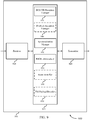
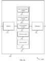
- FIG. 8 shows a block diagram 800 of an apparatus 805 for use in wireless communication, in accordance with various aspects of the present disclosure.
- the apparatus 805 may be an example of aspects of one or more of the UEs described with reference to FIGs. 1 and 3 .
- the apparatus 805 may include a receiver 810, a UE wireless communication manager 815, and a transmitter 820.
- the apparatus 805 may also include a processor. Each of these components may be in communication with one another (e.g., via one or more buses).
- the receiver 810 may receive data or control signals or information (i.e., transmissions), some or all of which may be associated with various information channels (e.g., data channels, control channels, etc.). Received signals or information, or measurements performed thereon, may be passed to other components of the apparatus 805.
- the receiver 810 may include one or a plurality of antennas.
- the transmitter 820 may transmit data or control signals or information (i.e., transmissions) generated by other components of the apparatus 805, some or all of which may be associated with various information channels (e.g., data channels, control channels, etc.).
- the transmitter 820 may be collocated with the receiver 810 in a transceiver.
- the transmitter 820 and receiver 810 may be an example of aspects of the transceiver(s) 1830 described with reference to FIG. 18 .
- the transmitter 820 may include one or a plurality of antennas, which may be separate from (or shared with) the one or more antennas used by the receiver 810.
- the UE wireless communication manager 815 and/or at least some of its various sub-components may be implemented in hardware, software executed by a processor, firmware, or any combination thereof. If implemented in software executed by a processor, the functions of the UE wireless communication manager 815 and/or at least some of its various sub-components may be executed by a general-purpose processor, a digital signal processor (DSP), an application-specific integrated circuit (ASIC), a field-programmable gate array (FPGA) or other programmable logic device, discrete gate or transistor logic, discrete hardware components, or any combination thereof designed to perform the functions described in the present disclosure.
- DSP digital signal processor
- ASIC application-specific integrated circuit
- FPGA field-programmable gate array
- the UE wireless communication manager 815 and/or at least some of its various sub-components may be physically located at various positions, including being distributed such that portions of functions are implemented at different physical locations by one or more physical devices.
- the UE wireless communication manager 815 and/or at least some of its various sub-components may be a separate and distinct component in accordance with various aspects of the present disclosure.
- the UE wireless communication manager 815 and/or at least some of its various sub-components may be combined with one or more other hardware components, including but not limited to an I/O component, a transceiver, another computing device, one or more other components described in the present disclosure, or a combination thereof, in accordance with various aspects of the present disclosure.
- the UE wireless communication manager 815 may be used to receive one or more of the SS blocks described with reference to FIGs. 2 and 4 ⁇ 7, and to determine the timing of a SS block from a TSS included in the SS block.
- the TSS may be based at least in part on a SS block index associated with the SS block.
- the UE wireless communication manager 815 may be used to receive a TSS that is outside of a SS block and based at least in part on a timing of the TSS within a BCH TTI.
- FIG. 9 shows a block diagram 900 of a wireless device 905 that supports communication of an SS block index in a timing synchronization signal in accordance with aspects of the present disclosure.
- Wireless device 905 may be an example of aspects of a wireless device 805 or a UE as described with reference to FIG. 8 .
- Wireless device 905 may include receiver 910, UE wireless communications manager 915, and transmitter 920.
- Wireless device 905 may also include a processor. Each of these components may be in communication with one another (e.g., via one or more buses).
- Receiver 910 may receive information such as packets, user data, or control information associated with various information channels (e.g., control channels, data channels, and information related to timing synchronization, for example. Information may be passed on to other components of the device.
- the receiver 910 may be an example of aspects of the transceiver 1830 described with reference to FIG. 18 .
- the receiver 910 may utilize a single antenna or a set of antennas.
- Transmitter 920 may transmit signals generated by other components of the device.
- the transmitter 920 may be collocated with a receiver 910 in a transceiver module.
- the transmitter 920 may be an example of aspects of the transceiver 1835 described with reference to FIG. 18 .
- the transmitter 920 may utilize a single antenna or a set of antennas.
- the UE wireless communication manager 915 may be an example of aspects of the UE wireless communication manager described with reference to FIG. 8 .
- the UE wireless communication manager 915 may include a BCH TTI reception manager 925, a synchronization manager 930, a PBCH demodulator 935, an optional SS block reception manager 940, and optional beam identifier 945. Each of these components may communicate, directly or indirectly, with one another (e.g., via one or more buses).
- the BCH TTI reception manager 925 may be used to receive a TSS and a PBCH, as described for example with reference to FIGs. 2 ⁇ 7.
- the TSS may be based at least in part on a timing of the TSS within a BCH TTI.
- the synchronization manager 930 may be used to determine the timing of the TSS within the BCH TTI, as described for example with reference to FIGs. 2 ⁇ 7.
- the PBCH demodulator 935 may be used to demodulate the PBCH based at least in part on the TSS, as described herein and for example with reference to FIGs. 2 ⁇ 7.
- the BCH TTI reception manager 925 or SS block reception manager 940 may be used to receive a SS block that includes a TSS and a PBCH, as described for example with reference to FIGs. 2 ⁇ 7.
- the TSS may be based at least in part on a SS block index associated with the SS block.
- the TSS may be based at least in part on the SS block index because the SS block index is encoded in a waveform signature of the TSS, or because the SS block index is included in at least one modulation symbol in the TSS.
- the SS block index may indicate the timing of the TSS within a BCH TTI, and may thus indicate the timing of the SS block within the BCH TTI.
- the SS block may further include a PSS and a SSS.
- the SSS may be based at least in part on a PCI of the base station.
- the SS block may be one SS block in a plurality of SS blocks within the BCH TTI.
- the TSS may include at least one modulation symbol.
- the at least one modulation symbol may include a QPSK symbol or a BPSK symbol.
- the synchronization manager 930 may be used to determine, based at least in part on the SS block index, the timing of the SS block, and thus the timing of the TSS, within the BCH TTI, as described for example with reference to FIGs. 2 ⁇ 7.
- the PBCH demodulator 935 may be used to demodulate the PBCH based at least in part on the TSS, as described herein and for example with reference to FIGs. 2 ⁇ 7.
- the TSS may be transmitted as a DMRS for the PBCH.
- the PBCH demodulator 935 determine a signal to noise ratio (SNR) and/or a signal to noise plus interference ratio (SINR) for the TSS transmitted via a wireless channel, and use the determined SNR and/or SINR for demodulating the PBCH.
- the PBCH demodulator 935 may use the TSS to generate a channel estimate (e.g., estimate of a phase shift caused to the TSS by transmission via a wireless channel), and use the channel estimate for demodulating the PBCH.
- the SS block includes a PSS and a SSS
- the PBCH may be further demodulated based at least in part on the SSS.
- the beam identifier 945 may optionally be used to identify, based at least in part on the SS block index, a beam on which the SS block is transmitted, as described for example with reference to FIGs. 2 ⁇ 7.
- the TSS payload decoder 950 may be used to decode a SS block index encoded in the at least one modulation symbol, as described for example with reference to FIGs. 2 ⁇ 7.
- receiving the TSS and the PBCH may include receiving the TSS time division multiplexed with the PBCH on a same set of one or more frequency subcarriers.
- the SS block may further include a PSS and a SSS, and receiving the TSS, the SSS, and the PBCH may include receiving the PBCH and the TSS after the SSS.
- receiving the TSS and the PBCH may include receiving the TSS on a first set of one or more frequency subcarriers that overlaps a second set of one or more frequency subcarriers on which the PBCH is received.
- the first set of one or more frequency subcarriers may be different from the second set of one or more frequency subcarriers.
- receiving the TSS and the PBCH may further include receiving the TSS frequency division multiplexed with at least a portion of the PBCH.
- the SS block may further include a PSS and a SSS, and receiving the SSS and the PBCH may include receiving a second portion of the PBCH after the SSS.
- receiving the TSS and the PBCH may include receiving the TSS on a first set of one or more frequency subcarriers that is interleaved with a second set of one or more frequency subcarriers on which the PBCH is received.
- the SS block may further include a PSS and a SSS, and receiving the TSS, the PSS, the SSS, and the PBCH may include receiving the PSS and the SSS frequency division multiplexed with the interleaved TSS and PBCH.
- the PBCH may be received based at least in part on the SS block index, and the UE wireless communication manager 915 may decode the PBCH based at least in part on the SS block index.
- FIG. 10 shows a block diagram 1000 of a wireless device 1005 that supports communication of an SS block index in a timing synchronization signal in accordance with aspects of the present disclosure.
- Wireless device 1005 may be an example of aspects of a wireless device 805 or a UE as described with reference to FIG. 8 .
- Wireless device 1005 may include receiver 1010, UE wireless communications manager 1015, and transmitter 1020.
- Wireless device 1005 may also include a processor. Each of these components may be in communication with one another (e.g., via one or more buses).
- Receiver 1010 may receive information such as packets, user data, or control information associated with various information channels (e.g., control channels, data channels, and information related to timing synchronization, for example. Information may be passed on to other components of the device.
- the receiver 1010 may be an example of aspects of the transceiver 1830 described with reference to FIG. 18 .
- the receiver 1010 may utilize a single antenna or a set of antennas.
- Transmitter 1020 may transmit signals generated by other components of the device.
- the transmitter 1020 may be collocated with a receiver 910 in a transceiver module.
- the transmitter 1020 may be an example of aspects of the transceiver 1835 described with reference to FIG. 18 .
- the transmitter 1020 may utilize a single antenna or a set of antennas.
- the UE wireless communication manager 1015 may be an example of aspects of the UE wireless communication manager described with reference to FIG. 8 .
- the UE wireless communication manager 1015 may include a BCH TTI reception manager 1025, an optional SS block reception manager 1030, a synchronization manager 1035, a TSS demodulator 1040, an optional beam identifier 1045, and an optional PBCH demodulator 1050. Each of these components may communicate, directly or indirectly, with one another (e.g., via one or more buses).
- the BCH TTI reception manager 1025 or SS block reception manager 1030 may be used to receive a SS block that includes a TSS, a PSS, and a SSS, as described for example with reference to FIGs. 2 ⁇ 4 and 6.
- the TSS may be based at least in part on a SS block index associated with the SS block.
- the TSS may be based at least in part on the SS block index because the SS block index is encoded in a waveform signature of the TSS, or because the SS block index is included in at least one modulation symbol in the TSS.
- the SS block index may indicate the timing of the TSS within a BCH TTI, and may thus indicate the timing of the SS block within the BCH TTI.
- the SSS may be based at least in part on a PCI of the base station.
- the SS block may be one SS block in a plurality of SS blocks within the BCH TTI.
- the synchronization manager 1035 may be used to determine, based at least in part on the SS block index, a timing of the SS block within the BCH TTI, as described for example with reference to FIGs. 2 ⁇ 4 and 6.
- the TSS demodulator 1040 may be used to demodulate the TSS based at least in part on the SSS, as described herein and for example with reference to FIGs. 2 ⁇ 4 and 6.
- the SSS may be transmitted as a DMRS for the TSS.
- the TSS demodulator 1040 may determine a signal to noise ratio (SNR) and/or a signal to noise plus interference ratio (SINR) for the SSS transmitted via a wireless channel, and use the determined SNR and/or SINR for demodulating the TSS.
- the TSS demodulator 1040 may use the SSS to generate a channel estimate (e.g., estimate of a phase shift caused to the SSS by transmission via a wireless channel), and use the channel estimate for demodulating the TSS.
- a channel estimate e.g., estimate of a phase shift caused to the SSS by transmission via a wireless channel
- the beam identifier 1045 may be used to identify, based at least in part on the SS block index, a beam on which the SS block is transmitted, as described for example with reference to FIGs. 2 ⁇ 4 and 6.
- the PBCH demodulator 1050 may be used to demodulate a PBCH based at least in part on the SSS, when the SS block includes the PBCH, as described herein and for example with reference to FIGs. 2 ⁇ 4 and 6.
- the BCH TTI reception manager 1025 or SS block reception manager 1030 may be used to receive the PBCH based at least in part on the SS block index, and the UE wireless communication manager 1015 may decode the PBCH, based at least in part on the SS block index.
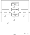
- FIG. 11 shows a block diagram 1100 of a wireless device 1105 that supports communication of an SS block index in a timing synchronization signal in accordance with aspects of the present disclosure.
- Wireless device 1105 may be an example of aspects of a wireless device 805 or a UE as described with reference to FIG. 8 .
- Wireless device 1105 may include receiver 1110, UE wireless communications manager 1115, and transmitter 1120.
- Wireless device 1105 may also include a processor. Each of these components may be in communication with one another (e.g., via one or more buses).
- Receiver 1110 may receive information such as packets, user data, or control information associated with various information channels (e.g., control channels, data channels, and information related to timing synchronization, for example. Information may be passed on to other components of the device.
- the receiver 1110 may be an example of aspects of the transceiver 1830 described with reference to FIG. 18 .
- the receiver 1110 may utilize a single antenna or a set of antennas.
- Transmitter 1120 may transmit signals generated by other components of the device.
- the transmitter 1120 may be collocated with a receiver 1110 in a transceiver module.
- the transmitter 1120 may be an example of aspects of the transceiver 1835 described with reference to FIG. 18 .
- the transmitter 1120 may utilize a single antenna or a set of antennas.
- the UE wireless communication manager 1115 may be an example of aspects of the UE wireless communication manager described with reference to FIG. 8 .
- the UE wireless communication manager 1115 may include a SS block reception manager 1125, a TSS payload decoder 1130, and a synchronization manager 1135. Each of these components may communicate, directly or indirectly, with one another (e.g., via one or more buses).
- the SS block reception manager 1125 may be used to receive a SS block that includes a TSS, as described for example with reference to FIGs. 2 ⁇ 7.
- the TSS may include at least one modulation symbol.
- the at least one modulation symbol may include a QPSK symbol or a BPSK symbol.
- the SS block may also include a PSS, a SSS, and/or a PBCH.
- the SSS may be based at least in part on a PCI of the base station.
- the SS block may be one SS block in a plurality of SS blocks within a BCH TTI.
- the TSS payload decoder 1130 may be used to decode a SS block index encoded in the at least one modulation symbol, as described for example with reference to FIGs. 2 ⁇ 7.
- the SS block index may indicate the timing of the TSS within a BCH TTI, and may thus indicate the timing of the SS block within the BCH TTI.
- the SS block index may be encoded in the at least one modulation symbol using a polar code, or a Reed-Mueller code, or a Golay code, or a TBCC.
- the TSS payload decoder 1130 may also be used to decode, from the at least one modulation symbol, at least one parameter of a beam sweep configuration used to receive a plurality of SS blocks, including the SS block, within the BCH TTI, as described for example with reference to FIGs. 2 ⁇ 7.
- the at least one parameter of the beam sweep configuration may include a number of beams in a SS block burst-set, or a periodicity of the SS block burst-set, or a combination thereof.
- the synchronization manager 1135 may be used to identify, based at least in part on the SS block index, a timing of the SS block within a BCH TTI, as described for example with reference to FIGs. 2 ⁇ 7.
- FIG. 12 shows a block diagram 1200 of a wireless device 1205 that supports communication of an SS block index in a timing synchronization signal in accordance with aspects of the present disclosure.
- Wireless device 1205 may be an example of aspects of a wireless device 805 or a UE as described with reference to FIG. 8 .
- Wireless device 1205 may include receiver 1210, UE wireless communications manager 1215, and transmitter 1220.
- Wireless device 1205 may also include a processor. Each of these components may be in communication with one another (e.g., via one or more buses).
- Receiver 1210 may receive information such as packets, user data, or control information associated with various information channels (e.g., control channels, data channels, and information related to timing synchronization, for example. Information may be passed on to other components of the device.
- the receiver 1210 may be an example of aspects of the transceiver 1830 described with reference to FIG. 18 .
- the receiver 1210 may utilize a single antenna or a set of antennas.
- Transmitter 1220 may transmit signals generated by other components of the device.
- the transmitter 1220 may be collocated with a receiver 1210 in a transceiver module.
- the transmitter 1220 may be an example of aspects of the transceiver 1835 described with reference to FIG. 18 .
- the transmitter 1220 may utilize a single antenna or a set of antennas.
- the UE wireless communication manager 1215 may be an example of aspects of the UE wireless communication manager described with reference to FIG. 8 .
- the UE wireless communication manager 1215 may include a BCH TTI reception manager 1225, an optional SS block reception manager 1230, a demodulator 1235, and a synchronization manager 1240. Each of these components may communicate, directly or indirectly, with one another (e.g., via one or more buses).
- the BCH TTI reception manager 1225 or SS block reception manager 1230 may be used to receive a SS block that includes a TSS and a PBCH, as described for example with reference to FIGs. 2 ⁇ 4 and 6.
- the TSS may be based at least in part on a SS block index associated with the SS block.
- the TSS may be based at least in part on the SS block index because the SS block index is encoded in a waveform signature of the TSS, or because the SS block index is included in at least one modulation symbol in the TSS.
- the SS block index may indicate the timing of the TSS within a BCH TTI, and may thus indicate the timing of the SS block within the BCH TTI.
- the SS block may further include a PSS and a SSS.
- the SSS may be based at least in part on a PCI of the base station.
- the SS block may be one SS block in a plurality of SS blocks within the BCH TTI.
- the demodulator 1235 may be used to demodulate the TSS and the PBCH based at least in part on a same DMRS, as described herein and for example with reference to FIGs. 2 ⁇ 4 and 6.
- the DMRS may be a SSS included in the SS block.
- the synchronization manager 1240 may be used to identify, based at least in part on the SS block index, a timing of the SS block within a BCH TTI, as described for example with reference to FIGs. 2 ⁇ 4 and 6.
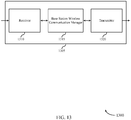
- FIG. 13 shows a block diagram 1300 of an apparatus 1305 that supports communication of an SS block index in a timing synchronization signal in accordance with aspects of the present disclosure.
- the apparatus 1305 may be an example of aspects of one or more of the base stations described with reference to FIGs. 1 and 3 .
- the apparatus 1305 may include a receiver 1310, a base station wireless communication manager 1315, and a transmitter 1320.
- the apparatus 1305 may also include a processor. Each of these components may be in communication with one another (e.g., via one or more buses).
- the receiver 1310 may receive data or control signals or information (i.e., transmissions), some or all of which may be associated with various information channels (e.g., data channels, control channels, etc.). Received signals or information, or measurements performed thereon, may be passed to other components of the apparatus 1305.
- the receiver 1310 may include one or a plurality of antennas.
- the transmitter 1320 may transmit data or control signals or information (i.e., transmissions) generated by other components of the apparatus 1305, some or all of which may be associated with various information channels (e.g., data channels, control channels, etc.).
- the transmitter 1320 may be collocated with the receiver 1310 in a transceiver.
- the transmitter 1320 and receiver 1310 may be an example of aspects of the transceiver(s) 1950 described with reference to FIG. 19 .
- the transmitter 1320 may include one or a plurality of antennas, which may be separate from (or shared with) the one or more antennas used by the receiver 1310.
- the base station wireless communication manager 1315 and/or at least some of its various sub-components may be implemented in hardware, software executed by a processor, firmware, or any combination thereof. If implemented in software executed by a processor, the functions of the base station wireless communication manager 1315 and/or at least some of its various sub-components may be executed by a general-purpose processor, a DSP, an ASIC, a FPGA or other programmable logic device, discrete gate or transistor logic, discrete hardware components, or any combination thereof designed to perform the functions described in the present disclosure.
- the base station wireless communication manager 1315 and/or at least some of its various sub-components may be physically located at various positions, including being distributed such that portions of functions are implemented at different physical locations by one or more physical devices.
- the base station wireless communication manager 1315 and/or at least some of its various sub-components may be a separate and distinct component in accordance with various aspects of the present disclosure.
- the base station wireless communication manager 1315 and/or at least some of its various sub-components may be combined with one or more other hardware components, including but not limited to an I/O component, a transceiver, another computing device, one or more other components described in the present disclosure, or a combination thereof, in accordance with various aspects of the present disclosure.
- the base station wireless communication manager 1315 may be used to transmit one or more of the SS blocks described with reference to FIGs. 2 and 4-7 .
- a SS block may include a TSS based at least in part on a SS block index associated with the SS block.
- the base station wireless communication manager 1315 may be used to transmit a TSS that is outside of a SS block and based at least in part on a timing of the TSS within a BCH TTI.
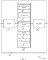
- FIG. 14 shows a block diagram 1400 of an apparatus 1405 that supports communication of an SS block index in a timing synchronization signal in accordance with aspects of the present disclosure.
- the apparatus 1305 may be an example of aspects of one or more of the base stations described with reference to FIGs. 1 and 3 .
- the apparatus 1405 may include a receiver 1410, a base station wireless communication manager 1415, and a transmitter 1420.
- the apparatus 1405 may also include a processor. Each of these components may be in communication with one another (e.g., via one or more buses).
- the receiver 1410 may receive data or control signals or information (i.e., transmissions), some or all of which may be associated with various information channels (e.g., data channels, control channels, etc.). Received signals or information, or measurements performed thereon, may be passed to other components of the apparatus 1405.
- the receiver 1410 may include one or a plurality of antennas.
- the transmitter 1420 may transmit data or control signals or information (i.e., transmissions) generated by other components of the apparatus 1405, some or all of which may be associated with various information channels (e.g., data channels, control channels, etc.).
- the transmitter 1420 may be collocated with the receiver 1410 in a transceiver.
- the transmitter 1420 and receiver 1410 may be an example of aspects of the transceiver(s) 1950 described with reference to FIG. 19 .
- the transmitter 1420 may include one or a plurality of antennas, which may be separate from (or shared with) the one or more antennas used by the receiver 1410.
- the base station wireless communication manager 1415 may be an example of aspects of the base station wireless communication manager described with reference to FIG. 13 .
- the base station wireless communication manager 1415 may include a BCH TTI resource allocator 1425, a TSS determiner 1430, a BCH TTI transmission manager 1435, and an optional SS block transmission manager 1440. Each of these components may communicate, directly or indirectly, with one another (e.g., via one or more buses).
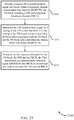
- the BCH TTI resource allocator 1425 may be used to allocate resources for a TSS and a PBCH within a BCH TTI, as described for example with reference to FIGs. 2 ⁇ 7.
- the TSS determiner 1430 may be used to determine the TSS based at least in part on a timing of the TSS within the BCH TTI, as described for example with reference to FIGs. 2 ⁇ 7.
- the BCH TTI transmission manager 1435 may be used to transmit, on the resources allocated for the TSS and the PBCH, the TSS and the PBCH, as described for example with reference to FIGs. 2 ⁇ 7.
- the TSS may be transmitted as a DMRS for the PBCH on at least one port used to transmit the TSS and the PBCH.
- the BCH TTI resource allocator 1425 may be used to allocate resources for a SS block within a BCH TTI, as described for example with reference to FIGs. 2 ⁇ 7.
- the SS block may include a TSS and a PBCH, and thus, resources may be allocated for the TSS and the PBCH in the SS block.
- the SS block may also include a PSS and a SSS, and resources may be allocated for the PSS and the SSS in the SS block.
- the SSS may be determined based at least in part on a PCI of the base station.
- the SS block may be one SS block in a plurality of SS blocks transmitted (e.g., by the base station) within the BCH TTI.
- the TSS determiner 1430 may be used to determine the TSS based at least in part on a timing of the TSS within the BCH TTI, as described for example with reference to FIGs. 2 ⁇ 7.
- the timing of the TSS may be based at least in part on a SS block index associated with the SS block.
- the SS block index may indicate the timing of the TSS within the BCH TTI, and thus, the TSS may be determined based at least in part on the SS block index.
- the TSS may be determined based at least in part on the SS block index by encoding the SS block index in a waveform signature of the TSS, or by including the SS block index in at least one modulation symbol in the TSS.
- the SS block index may further identify a beam on which the SS block is transmitted.
- the TSS payload encoder 1445 may be used to encode a SS block index in at least one modulation symbol, as described for example with reference to FIGs. 2 ⁇ 7.
- the at least one modulation symbol may include a QPSK symbol or a BPSK symbol.
- the BCH TTI transmission manager 1435 or SS block transmission manager 1440 may be used to transmit, on the resources allocated for the SS block, the TSS and the PBCH, as described for example with reference to FIGs. 2 ⁇ 7.
- the TSS may be transmitted as a DMRS for the PBCH on at least one port used to transmit the TSS and the PBCH.
- the SSS may be transmitted as an additional DMRS for the PBCH, on at least one port used to transmit the SSS and the PBCH.
- the PBCH may be transmitted based at least in part on the SS block index for the SS block.
- transmitting the TSS and the PBCH may include transmitting the TSS time division multiplexed with the PBCH on a same set of one or more frequency subcarriers.
- the SS block may further include a PSS and a SSS, and transmitting the TSS, the SSS, and the PBCH may include transmitting the PBCH and the TSS after the SSS.
- transmitting the TSS and the PBCH may include transmitting the TSS on a first set of one or more frequency subcarriers that overlaps a second set of one or more frequency subcarriers on which the PBCH is transmitted.
- the first set of one or more frequency subcarriers may be different from the second set of one or more frequency subcarriers.
- transmitting the TSS and the PBCH may further include transmitting the TSS frequency division multiplexed with at least a portion of the PBCH.
- the SS block may further include a PSS and a SSS, and transmitting the SSS and the PBCH may include transmitting a second portion of the PBCH after the SSS.
- transmitting the TSS and the PBCH may include transmitting the TSS on a first set of one or more frequency subcarriers that is interleaved with a second set of one or more frequency subcarriers on which the PBCH is transmitted.
- the SS block may further include a PSS and a SSS, and transmitting the TSS, the PSS, the SSS, and the PBCH may include transmitting the PSS and the SSS frequency division multiplexed with the interleaved TSS and PBCH.
- FIG. 15 shows a block diagram 1500 of an apparatus 1505 that supports communication of an SS block index in a timing synchronization signal in accordance with aspects of the present disclosure.
- the apparatus 1505 may be an example of aspects of one or more of the base stations described with reference to FIGs. 1 and 3 .
- the apparatus 1505 may include a receiver 1510, a base station wireless communication manager 1515, and a transmitter 1520.
- the apparatus 1505 may also include a processor. Each of these components may be in communication with one another (e.g., via one or more buses).
- the receiver 1510 may receive data or control signals or information (i.e., transmissions), some or all of which may be associated with various information channels (e.g., data channels, control channels, etc.). Received signals or information, or measurements performed thereon, may be passed to other components of the apparatus 1505.
- the receiver 1510 may include one or a plurality of antennas.
- the transmitter 1520 may transmit data or control signals or information (i.e., transmissions) generated by other components of the apparatus 1505, some or all of which may be associated with various information channels (e.g., data channels, control channels, etc.).
- the transmitter 1520 may be collocated with the receiver 1510 in a transceiver.
- the transmitter 1520 and receiver 1510 may be an example of aspects of the transceiver(s) 1950 described with reference to FIG. 19 .
- the transmitter 1520 may include one or a plurality of antennas, which may be separate from (or shared with) the one or more antennas used by the receiver 1510.
- the base station wireless communication manager 1515 may be an example of aspects of the base station wireless communication manager described with reference to FIG. 13 .
- the base station wireless communication manager 1515 may include a SS block resource allocator 1525, a TSS determiner 1530, a BCH TTI transmission manager 1535. an optional SS block transmission manager 1540. Each of these components may communicate, directly or indirectly, with one another (e.g., via one or more buses).
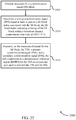
- the SS block resource allocator 1525 may be used to allocate resources for a SS block, as described for example with reference to FIGs. 2-4 and 6 .
- the SS block may include a TSS, a PSS, and a SSS, and thus, resources may be allocated for the TSS, the PSS, and the SSS in the SS block.
- the SSS may be determined based at least in part on a PCI of the base station.
- the SS block may also include a PBCH, and resources may be allocated for the PBCH in the SS block.
- the SS block may be one SS block in a plurality of SS blocks transmitted (e.g., by the base station) within a BCH TTI.
- the TSS determiner 1530 may be used to determine the TSS based at least in part on a timing of the TSS within the BCH TTI, as described for example with reference to FIGs. 2 ⁇ 4 and 6.
- the timing of the TSS may be based at least in part on a SS block index associated with the SS block.
- the SS block index may indicate the timing of the TSS within the BCH TTI, and thus, the TSS may be determined based at least in part on the SS block index.
- the TSS may be determined based at least in part on the SS block index by encoding the SS block index in a waveform signature of the TSS, or by including the SS block index in at least one modulation symbol in the TSS.
- the SS block index may further identify a beam on which the SS block is transmitted.
- the BCH TTI transmission manager 1535 or SS block transmission manager 1540 may be used to transmit, on the resources allocated for the SS block, the TSS the PSS, and the SSS, as described for example with reference to FIGs. 2 ⁇ 4 and 6.
- the SSS may be transmitted as a DMRS for the TSS on at least one port used to transmit the TSS and the SSS.
- the SSS may also be transmitted as a DMRS for the PBCH, on at least one port used to transmit the SSS and the PBCH.
- the PBCH may be transmitted based at least in part on the SS block index for the SS block.
- the BCH TTI transmission manager 1535 or SS block transmission manager 1540 may be used to transmit the TSS time division multiplexed with the PBCH on a same set of one or more frequency subcarriers.
- transmitting the TSS, the SSS, and the PBCH may include transmitting the PBCH and the TSS after the SSS.
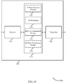
- FIG. 16 shows a block diagram 1600 of an apparatus 1605 that supports communication of an SS block index in a timing synchronization signal in accordance with aspects of the present disclosure.
- the apparatus 1605 may be an example of aspects of one or more of the base stations described with reference to FIGs. 1 and 3 .
- the apparatus 1605 may include a receiver 1610, a base station wireless communication manager 1615, and a transmitter 1620.
- the apparatus 1605 may also include a processor. Each of these components may be in communication with one another (e.g., via one or more buses).
- the receiver 1610 may receive data or control signals or information (i.e., transmissions), some or all of which may be associated with various information channels (e.g., data channels, control channels, etc.). Received signals or information, or measurements performed thereon, may be passed to other components of the apparatus 1605.
- the receiver 1610 may include one or a plurality of antennas.
- the transmitter 1620 may transmit data or control signals or information (i.e., transmissions) generated by other components of the apparatus 1605, some or all of which may be associated with various information channels (e.g., data channels, control channels, etc.).
- the transmitter 1620 may be collocated with the receiver 1610 in a transceiver.
- the transmitter 1620 and receiver 1610 may be an example of aspects of the transceiver(s) 1950 described with reference to FIG. 19 .
- the transmitter 1620 may include one or a plurality of antennas, which may be separate from (or shared with) the one or more antennas used by the receiver 1610.
- the base station wireless communication manager 1615 may be an example of aspects of the base station wireless communication manager described with reference to FIG. 13 .
- the base station wireless communication manager 1615 may include a SS block resource allocator 1625, a TSS payload encoder 1630, a SS block transmission manager 1635, or an optional TSS transmission manager 1640. Each of these components may communicate, directly or indirectly, with one another (e.g., via one or more buses).
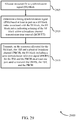
- the SS block resource allocator 1625 may be used to allocate resources for a SS block, as described for example with reference to FIGs. 2 ⁇ 7.
- the SS block may include a TSS, a PSS, a SSS, and/or a PBCH, and thus, resources may be allocated for the TSS, the PSS, the SSS, and/or the PBCH in the SS block.
- the SSS may be determined based at least in part on a PCI of the base station.
- the SS block may be one SS block in a plurality of SS blocks transmitted (e.g., by the base station) within a BCH TTI.
- the TSS payload encoder 1630 may be used to encode a SS block index in at least one modulation symbol, as described for example with reference to FIGs. 2-7 .
- the at least one modulation symbol may include a QPSK symbol or a BPSK symbol.
- the SS block index may indicate a timing of the TSS within a BCH TTI, and may thus indicate the timing of the SS block within the BCH TTI.
- the SS block index may be encoded in the at least one modulation symbol using a polar code, or a Reed-Mueller code, or a Golay code, or a TBCC.
- the TSS payload encoder 1630 may also be used to encode, in the at least one modulation symbol, at least one parameter of a beam sweep configuration used to transmit a plurality of SS blocks, including the SS block, within the BCH TTI, as described for example with reference to FIGs. 2 ⁇ 7.
- the at least one parameter of the beam sweep configuration may include a number of beams in a SS block burst-set, or a periodicity of the SS block burst-set, or a combination thereof.
- the SS bock transmission manager 1635 or TSS transmission manager 1640 may be used to transmit, on the resources allocated for the SS block, a TSS that includes the at least one modulation symbol, as described for example with reference to FIGs. 2 ⁇ 7.
- the base station wireless communication manager 1615 may be used to generate a CRC for the SS block index, and to encode the CRC in the at least one modulation symbol, along with the SS block index.
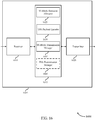
- FIG. 17 shows a block diagram 1700 of an apparatus 1705 that supports communication of an SS block index in a timing synchronization signal in accordance with aspects of the present disclosure.
- the apparatus 1705 may be an example of aspects of one or more of the base stations described with reference to FIGs. 1 and 3 .
- the apparatus 1705 may include a receiver 1710, a base station wireless communication manager 1715, and a transmitter 1720.
- the apparatus 1705 may also include a processor. Each of these components may be in communication with one another (e.g., via one or more buses).
- the receiver 1710 may receive data or control signals or information (i.e., transmissions), some or all of which may be associated with various information channels (e.g., data channels, control channels, etc.). Received signals or information, or measurements performed thereon, may be passed to other components of the apparatus 1705.
- the receiver 1710 may include one or a plurality of antennas.
- the transmitter 1720 may transmit data or control signals or information (i.e., transmissions) generated by other components of the apparatus 1705, some or all of which may be associated with various information channels (e.g., data channels, control channels, etc.).
- the transmitter 1720 may be collocated with the receiver 1710 in a transceiver.
- the transmitter 1720 and receiver 1710 may be an example of aspects of the transceiver(s) 1950 described with reference to FIG. 19 .
- the transmitter 1720 may include one or a plurality of antennas, which may be separate from (or shared with) the one or more antennas used by the receiver 1710.
- the base station wireless communication manager 1715 may be an example of aspects of the base station wireless communication manager described with reference to FIG. 13 .
- the base station wireless communication manager 1715 may include a SS block resource allocator 1725, a TSS determiner 1730, and a BCH TTI transmission manager 1735. Each of these components may communicate, directly or indirectly, with one another (e.g., via one or more buses).
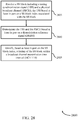
- the SS block resource allocator 1725 may be used to allocate resources for a SS block, as described for example with reference to FIGs. 2 ⁇ 4 and 6.
- the SS block may include a TSS and a PBCH, and thus, resources may be allocated for the TSS and the PBCH in the SS block.
- the SS block may also include a PSS and a SSS, and resources in the SS block may be allocated for the PSS and the SSS.
- the SSS may be determined based at least in part on a PCI of the base station.
- the SS block may be one SS block in a plurality of SS blocks transmitted (e.g., by the base station) within a BCH TTI.
- the TSS determiner 1730 may be used to determine a TSS based at least in part on a SS block index associated with the SS block, as described for example with reference to FIGs. 2 ⁇ 4 and 6.
- the SS block index may indicate a timing of the SS block within a BCH TTI.
- the BCH TTI transmission manager 1735 may be used to transmit, on the resources allocated for the SS block, the TSS and the PBCH, as described for example with reference to FIGs. 2 ⁇ 4 and 6.
- the transmitted SS block may include a same DMRS for the TSS and the PBCH on at least one port used to transmit the DMRS, the TSS, and the PBCH.
- the DMRS may include a SSS in the SS block.
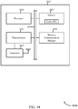
- FIG. 18 shows a block diagram 1800 of a UE 1815 for use in wireless communication, in accordance with various aspects of the present disclosure.
- the UE 1815 may be included or be part of a personal computer (e.g., a laptop computer, a netbook computer, a tablet computer, etc.), a cellular telephone, a PDA, a digital video recorder (DVR), an internet appliance, a gaming console, an e-reader, a vehicle, a home appliance, a lighting or alarm control system, etc.
- the UE 1815 may, in some examples, have an internal power supply (not shown), such as a small battery, to facilitate mobile operation.
- the UE 1815 may be an example of aspects of one or more of the UEs described with reference to FIGs. 1 and 3 , or aspects of the apparatus described with reference to FIG. 8 .
- the UE 1815 may be configured to implement at least some of the UE or apparatus techniques or functions described with reference to FIGs. 1 ⁇ 12.
- the UE 1815 may include a processor 1810, a memory 1820, at least one transceiver (represented by transceiver(s) 1830), antennas 1840 (e.g., an antenna array), or a UE wireless communication manager 1850. Each of these components may be in communication with each other, directly or indirectly, over one or more buses 1835.
- the memory 1820 may include random access memory (RAM) or read-only memory (ROM).
- the memory 1820 may store computer-readable, computer-executable code 1825 containing instructions that are configured to, when executed, cause the processor 1810 to perform various functions described herein related to wireless communication, including, for example, receiving a TSS and/or SS blocks.
- the computer-executable code 1825 may not be directly executable by the processor 1810 but be configured to cause the UE 1815 (e.g., when compiled and executed) to perform various of the functions described herein.
- the processor 1810 may include an intelligent hardware device, e.g., a central processing unit (CPU), a microcontroller, an ASIC, etc.
- the processor 1810 may process information received through the transceiver(s) 1830 or information to be sent to the transceiver(s) 1830 for transmission through the antennas 1840.
- the processor 1810 may handle, alone or in connection with the UE wireless communication manager 1850, one or more aspects of communicating over (or managing communications over) one or more radio frequency spectrum bands.
- the transceiver(s) 1830 may include a modem configured to modulate packets and provide the modulated packets to the antennas 1840 for transmission, and to demodulate packets received from the antennas 1840.
- the transceiver(s) 1830 may, in some examples, be implemented as one or more transmitters and one or more separate receivers.
- the transceiver(s) 1830 may support communications in one or more radio frequency spectrum bands.
- the transceiver(s) 1830 may be configured to communicate bi-directionally, via the antennas 1840, with one or more base stations or apparatuses, such as one or more of the base stations described with reference to FIG. 1 , 3 , or 13 .
- the UE wireless communication manager 1850 may be configured to perform or control some or all of the UE or apparatus techniques or functions described with reference to FIGs. 1 ⁇ 12.
- the UE wireless communication manager 1850, or portions of it, may include a processor, or some or all of the functions of the UE wireless communication manager 1850 may be performed by the processor 1810 or in connection with the processor 1810.
- the UE wireless communication manager 1850 may be an example of aspects of one or more of the UE wireless communication managers described with reference to FIGs. 8 ⁇ 12.
- FIG. 19 shows a block diagram 1900 of a base station 1905 for use in wireless communication, in accordance with various aspects of the present disclosure.
- the base station 1905 may be an example of aspects of one or more of the base stations described with reference to FIGs. 1 and 3 , or aspects of the apparatus described with reference to FIG. 13 .
- the base station 1905 may be configured to implement or facilitate at least some of the base station or apparatus techniques or functions described with reference to FIGs. 1 ⁇ 7 and 13 ⁇ 17.
- the base station 1905 may include a processor 1910, a memory 1920, at least one transceiver (represented by transceiver(s) 1950), at least one antenna 1955 (e.g., an antenna array), or a base station wireless communication manager 1960.
- the base station 1905 may also include one or more of a base station communicator 1930 or a network communicator 1940. Each of these components may be in communication with each other, directly or indirectly, over one or more buses 1935.
- the memory 1920 may include RAM or ROM.
- the memory 1920 may store computer-readable, computer-executable code 1925 containing instructions that are configured to, when executed, cause the processor 1910 to perform various functions described herein related to wireless communication, including, for example, allocating resources for SS blocks and transmitting TSSs in the SS blocks.
- the computer-executable code 1925 may not be directly executable by the processor 1910 but be configured to cause the base station 1905 (e.g., when compiled and executed) to perform various of the functions described herein.
- the processor 1910 may include an intelligent hardware device, e.g., a CPU, a microcontroller, an ASIC, etc.
- the processor 1910 may process information received through the transceiver(s) 1950, the base station communicator 1930, or the network communicator 1940.
- the processor 1910 may also process information to be sent to the transceiver(s) 1950 for transmission through the antennas 1955, or to the base station communicator 1930 for transmission to one or more other base stations (e.g., base station 1905-a and base station 1905-b), or to the network communicator 1940 for transmission to a core network 1945, which may be an example of one or more aspects of the core network 130 described with reference to FIG. 1 .
- the processor 1910 may handle, alone or in connection with the base station wireless communication manager 1960, one or more aspects of communicating over (or managing communications over) one or more radio frequency spectrum bands.
- the transceiver(s) 1950 may include a modem configured to modulate packets and provide the modulated packets to the antennas 1955 for transmission, and to demodulate packets received from the antennas 1955.
- the transceiver(s) 1950 may, in some examples, be implemented as one or more transmitters and one or more separate receivers.
- the transceiver(s) 1950 may support communications in one or more radio frequency spectrum bands.
- the transceiver(s) 1950 may be configured to communicate bi-directionally, via the antennas 1955, with one or more UEs or apparatuses, such as one or more of the UEs or apparatus described with reference to FIG. 1 , 3 , 8 , or 18 .
- the base station 1905 may communicate with the core network 1945 through the network communicator 1940.
- the base station 1905 may also communicate with other base stations, such as the base station 1905-a and the base station 1905-b, using the base station communicator 1930.
- the base station wireless communication manager 1960 may be configured to perform or control some or all of the base station or apparatus techniques or functions described with reference to FIGs. 1 ⁇ 7 and 13 ⁇ 17.
- the base station wireless communication manager 1960, or portions of it, may include a processor, or some or all of the functions of the base station wireless communication manager 1960 may be performed by the processor 1910 or in connection with the processor 1910.
- the base station wireless communication manager 1960 may be an example of aspects of one or more of the base station wireless communication managers described with reference to FIGs. 13 ⁇ 17.
- FIG. 20 is a flow chart illustrating an example of a method 2000 for wireless communication at a UE, in accordance with various aspects of the present disclosure.
- the method 2000 is described below with reference to aspects of one or more of the UEs described with reference to FIGs. 1 , 3 , and 18 , aspects of the apparatus described with reference to FIG. 8 , or aspects of one or more of the UE wireless communication managers described with reference to FIGs. 8 ⁇ 12 and 18.
- a UE may execute one or more sets of codes to control the functional elements of the UE to perform the functions described below. Additionally or alternatively, the UE may perform one or more of the functions described below using special-purpose hardware.
- the method 2000 may include receiving a TSS and a PBCH, as described for example with reference to FIGs. 2 ⁇ 7.
- the TSS may be based at least in part on a timing of the TSS within a BCH TTI.
- the operation(s) at block 2005 may be performed using the BCH TTI reception manager 925 described with reference to FIG. 9 .
- the method 2200 may include determining the timing of the TSS within the BCH TTI, as described for example with reference to FIGs. 2 ⁇ 7.
- the operation(s) at block 2010 may be performed using the synchronization manager 930 described with reference to FIG. 9 .
- the method 2000 may include demodulating the PBCH based at least in part on the TSS, as described for example with reference to FIGs. 2 ⁇ 7.
- the operation(s) at block 2015 may be performed using the PBCH demodulator 935 described with reference to FIG. 9 .
- FIG. 21 is a flow chart illustrating an example of a method 2100 for wireless communication at a UE, in accordance with various aspects of the present disclosure.
- the method 2100 is described below with reference to aspects of one or more of the UEs described with reference to FIGs. 1 , 3 , and 18 , aspects of the apparatus described with reference to FIG. 8 , or aspects of one or more of the UE wireless communication managers described with reference to FIGs. 8 ⁇ 12 and 18.
- a UE may execute one or more sets of codes to control the functional elements of the UE to perform the functions described below. Additionally or alternatively, the UE may perform one or more of the functions described below using special-purpose hardware.
- the method 2100 may include receiving a SS block that includes a TSS and a PBCH, as described for example with reference to FIGs. 2 ⁇ 7.
- the TSS may be based at least in part on a SS block index associated with the SS block.
- the TSS may be based at least in part on the SS block index because the SS block index is encoded in a waveform signature of the TSS, or because the SS block index is included in at least one modulation symbol in the TSS.
- the SS block index may indicate the timing of the TSS within a BCH TTI, and may thus indicate the timing of the SS block within the BCH TTI.
- the SS block may further include a PSS and a SSS.
- the SSS may be based at least in part on a PCI of the base station.
- the SS block may be one SS block in a plurality of SS blocks within the BCH TTI.
- the operation(s) at block 2105 may be performed using the BCH TTI reception manager 925 or SS block reception manager 940 described with reference to FIG. 9 .
- the method 2100 may include determining, based at least in part on the SS block index, the timing of the SS block, and thus the timing of the TSS, within the BCH TTI, as described for example with reference to FIGs. 2 ⁇ 7.
- the operation(s) at block 2110 may be performed using the synchronization manager 930 described with reference to FIG. 9 .
- the method 2100 may include demodulating the PBCH based at least in part on the TSS, as described for example with reference to FIGs. 2 ⁇ 7.
- the PBCH may be further demodulated based at least in part on the SSS.
- the operation(s) at block 2115 may be performed using the PBCH demodulator 935 described with reference to FIG. 9 .
- the method 2100 may optionally include identifying, based at least in part on the SS block index, a beam on which the SS block is transmitted, as described for example with reference to FIGs. 2 ⁇ 7.
- the operation(s) at block 2120 may be performed using the beam identifier 945 described with reference to FIG. 9 .
- receiving the TSS and the PBCH may include receiving the TSS time division multiplexed with the PBCH on a same set of one or more frequency subcarriers.
- the SS block may further include a PSS and a SSS, and receiving the TSS, the SSS, and the PBCH may include receiving the PBCH and the TSS after the SSS.
- receiving the TSS and the PBCH may include receiving the TSS on a first set of one or more frequency subcarriers that overlaps a second set of one or more frequency subcarriers on which the PBCH is received.
- the first set of one or more frequency subcarriers may be different from the second set of one or more frequency subcarriers.
- receiving the TSS and the PBCH may further include receiving the TSS frequency division multiplexed with at least a portion of the PBCH.
- the SS block may further include a PSS and a SSS, and receiving the SSS and the PBCH may include receiving a second portion of the PBCH after the SSS.
- receiving the TSS and the PBCH may include receiving the TSS on a first set of one or more frequency subcarriers that is interleaved with a second set of one or more frequency subcarriers on which the PBCH is received.
- the SS block may further include a PSS and a SSS, and receiving the TSS, the PSS, the SSS, and the PBCH may include receiving the PSS and the SSS frequency division multiplexed with the interleaved TSS and PBCH.
- the PBCH may be received based at least in part on the SS block index, and the method 2100 may include decoding the PBCH, based at least in part on the SS block index.
- FIG. 22 is a flow chart illustrating an example of a method 2200 for wireless communication at a base station, in accordance with various aspects of the present disclosure.
- the method 2200 is described below with reference to aspects of one or more of the base stations described with reference to FIGs. 1 , 3 , and 19 , aspects of the apparatus described with reference to FIG. 13 , or aspects of one or more of the base station wireless communication managers described with reference to FIGs. 13 ⁇ 17 and 19.
- a base station may execute one or more sets of codes to control the functional elements of the base station to perform the functions described below. Additionally or alternatively, the base station may perform one or more of the functions described below using special-purpose hardware.
- the method 2200 may include allocating resources for a TSS and a PBCH within a BCH TTI, as described for example with reference to FIGs. 2 ⁇ 7.
- the operation(s) at block 2205 may be performed using the BCH TTI resource allocator 1425 described with reference to FIG. 14 .
- the method 2200 may include determining the TSS based at least in part on a timing of the TSS within the BCH TTI, as described for example with reference to FIGs. 2 ⁇ 7.
- the operation(s) at block 2205 may be performed using the TSS determiner 1430 described with reference to FIG. 14 .
- the method 2200 may include transmitting, on the resources allocated for the TSS and the PBCH, the TSS and the PBCH, as described for example with reference to FIGs. 2 ⁇ 7.
- the TSS may be transmitted as a DMRS for the PBCH on at least one port used to transmit the TSS and the PBCH.
- the operation(s) at block 2215 may be performed using the BCH TTI transmission manager 1435 described with reference to FIG. 14 .
- FIG. 23 is a flow chart illustrating an example of a method 2300 for wireless communication at a base station, in accordance with various aspects of the present disclosure.
- the method 2300 is described below with reference to aspects of one or more of the base stations described with reference to FIGs. 1 , 3 , and 19 , aspects of the apparatus described with reference to FIG. 13 , or aspects of one or more of the base station wireless communication managers described with reference to FIGs. 13 ⁇ 17 and 19.
- a base station may execute one or more sets of codes to control the functional elements of the base station to perform the functions described below. Additionally or alternatively, the base station may perform one or more of the functions described below using special-purpose hardware.
- the method 2300 may include allocating resources for a SS block within a BCH TTI, as described for example with reference to FIGs. 2 ⁇ 7.
- the SS block may include a TSS and a PBCH, and thus, resources may be allocated for the TSS and the PBCH in the SS block.
- the SS block may also include a PSS and a SSS, and resources may be allocated for the PSS and the SSS in the SS block.
- the SSS may be determined based at least in part on a PCI of the base station.
- the SS block may be one SS block in a plurality of SS blocks transmitted (e.g., by the base station) within the BCH TTI.
- the operation(s) at block 2305 may be performed using the BCH TTI resource allocator 1425 described with reference to FIG. 14 .
- the method 2300 may include determining the TSS based at least in part on a timing of the TSS within the BCH TTI, as described for example with reference to FIGs. 2 ⁇ 7.
- the timing of the TSS may be based at least in part on a SS block index associated with the SS block.
- the SS block index may indicate the timing of the TSS within the BCH TTI, and thus, the TSS may be determined based at least in part on the SS block index.
- the TSS may be determined based at least in part on the SS block index by encoding the SS block index in a waveform signature of the TSS, or by including the SS block index in at least one modulation symbol in the TSS.
- the SS block index may further identify a beam on which the SS block is transmitted.
- the operation(s) at block 2305 may be performed using the TSS determiner 1430 described with reference to FIG. 14 .
- the method 2300 may include transmitting, on the resources allocated for the SS block, the TSS and the PBCH, as described for example with reference to FIGs. 2 ⁇ 7.
- the TSS may be transmitted as a DMRS for the PBCH on at least one port used to transmit the TSS and the PBCH.
- the SSS may be transmitted as an additional DMRS for the PBCH, on at least one port used to transmit the SSS and the PBCH.
- the PBCH may be transmitted based at least in part on the SS block index for the SS block.
- the operation(s) at block 2315 may be performed using the BCH TTI transmission manager 1435 or described with reference to FIG. 14 .
- transmitting the TSS and the PBCH may include transmitting the TSS time division multiplexed with the PBCH on a same set of one or more frequency subcarriers.
- the SS block may further include a PSS and a SSS, and transmitting the TSS, the SSS, and the PBCH may include transmitting the PBCH and the TSS after the SSS.
- transmitting the TSS and the PBCH may include transmitting the TSS on a first set of one or more frequency subcarriers that overlaps a second set of one or more frequency subcarriers on which the PBCH is transmitted.
- the first set of one or more frequency subcarriers may be different from the second set of one or more frequency subcarriers.
- transmitting the TSS and the PBCH may further include transmitting the TSS frequency division multiplexed with at least a portion of the PBCH.
- the SS block may further include a PSS and a SSS, and transmitting the SSS and the PBCH may include transmitting a second portion of the PBCH after the SSS.
- transmitting the TSS and the PBCH may include transmitting the TSS on a first set of one or more frequency subcarriers that is interleaved with a second set of one or more frequency subcarriers on which the PBCH is transmitted.
- the SS block may further include a PSS and a SSS, and transmitting the TSS, the PSS, the SSS, and the PBCH may include transmitting the PSS and the SSS frequency division multiplexed with the interleaved TSS and PBCH.
- FIG. 24 is a flow chart illustrating an example of a method 2400 for wireless communication at a UE, in accordance with various aspects of the present disclosure.
- the method 2400 is described below with reference to aspects of one or more of the UEs described with reference to FIGs. 1 , 3 , and 18 , aspects of the apparatus described with reference to FIG. 8 , or aspects of one or more of the UE wireless communication managers described with reference to FIGs. 8 ⁇ 12 and 18.
- a UE may execute one or more sets of codes to control the functional elements of the UE to perform the functions described below. Additionally or alternatively, the UE may perform one or more of the functions described below using special-purpose hardware.
- the method 2400 may include receiving a SS block that includes a TSS, a PSS, and a SSS, as described for example with reference to FIGs. 2 ⁇ 4 and 6.
- the TSS may be based at least in part on a SS block index associated with the SS block.
- the TSS may be based at least in part on the SS block index because the SS block index is encoded in a waveform signature of the TSS, or because the SS block index is included in at least one modulation symbol in the TSS.
- the SS block index may indicate the timing of the TSS within a BCH TTI, and may thus indicate the timing of the SS block within the BCH TTI.
- the SSS may be based at least in part on a PCI of the base station.
- the SS block may be one SS block in a plurality of SS blocks within the BCH TTI.
- the operation(s) at block 2405 may be performed using the BCH TTI reception manager 1025 or SS block reception manager 1030 described with reference to FIG. 10 .
- the method 2400 may include determining, based at least in part on the SS block index, a timing of the SS block within the BCH TTI, as described for example with reference to FIGs. 2 ⁇ 4 and 6.
- the operation(s) at block 2410 may be performed using the synchronization manager 1035 described with reference to FIG. 10 .
- the method 2400 may include demodulating the TSS based at least in part on the SSS, as described herein and for example with reference to FIGs. 2 ⁇ 4 and 6.
- the operation(s) at block 2415 may be performed using the TSS demodulator 1040 described with reference to FIG. 10 .
- the method 2400 may optionally include identifying, based at least in part on the SS block index, a beam on which the SS block is transmitted, as described for example with reference to FIGs. 2 ⁇ 4 and 6.
- the operation(s) at block 2420 may be performed using the beam identifier 1045 described with reference to FIG. 10 .
- the method 2400 may optionally include demodulating the PBCH based at least in part on the SSS, as described herein and for example with reference to FIGs. 2 ⁇ 4 and 6.
- the operation(s) at block 2425 may be performed using the PBCH demodulator 1050 described with reference to FIG. 10 .
- the SS block may include a PBCH
- receiving the TSS and the PBCH may include receiving the TSS time division multiplexed with the PBCH on a same set of one or more frequency subcarriers.
- receiving the TSS, the SSS, and the PBCH may include receiving the PBCH and the TSS after the SSS.
- the PBCH may be received based at least in part on the SS block index, and the method 2100 may include decoding the PBCH, based at least in part on the SS block index.
- FIG. 25 is a flow chart illustrating an example of a method 2500 for wireless communication at a base station, in accordance with various aspects of the present disclosure.
- the method 2500 is described below with reference to aspects of one or more of the base stations described with reference to FIGs. 1 , 3 , and 19 , aspects of the apparatus described with reference to FIG. 13 , or aspects of one or more of the base station wireless communication managers described with reference to FIGs. 13 ⁇ 17 and 19.
- a base station may execute one or more sets of codes to control the functional elements of the base station to perform the functions described below. Additionally or alternatively, the base station may perform one or more of the functions described below using special-purpose hardware.
- the method 2500 may include allocating resources for a SS block, as described for example with reference to FIGs. 2 ⁇ 4 and 6.
- the SS block may include a TSS, a PSS, and a SSS, and thus, resources may be allocated for the TSS, the PSS, and the SSS in the SS block.
- the SSS may be determined based at least in part on a PCI of the base station.
- the SS block may also include a PBCH, and resources may be allocated for the PBCH in the SS block.
- the SS block may be one SS block in a plurality of SS blocks transmitted (e.g., by the base station) within a BCH TTI.
- the operation(s) at block 2505 may be performed using the SS block resource allocator 1525 described with reference to FIG. 15 .
- the method 2500 may include determining the TSS based at least in part on a timing of the TSS within the BCH TTI, as described for example with reference to FIGs. 2 ⁇ 4 and 6.
- the timing of the TSS may be based at least in part on a SS block index associated with the SS block.
- the SS block index may indicate the timing of the TSS within the BCH TTI, and thus, the TSS may be determined based at least in part on the SS block index.
- the TSS may be determined based at least in part on the SS block index by encoding the SS block index in a waveform signature of the TSS, or by including the SS block index in at least one modulation symbol in the TSS.
- the SS block index may further identify a beam on which the SS block is transmitted.
- the operation(s) at block 2505 may be performed using the TSS determiner 1530 described with reference to FIG. 15 .
- the method 2500 may include transmitting, on the resources allocated for the SS block, the TSS the PSS, and the SSS, as described for example with reference to FIGs. 2 ⁇ 4 and 6.
- the SSS may be transmitted as a DMRS for the TSS on at least one port used to transmit the TSS and the SSS.
- the SSS may also be transmitted as a DMRS for the PBCH, on at least one port used to transmit the SSS and the PBCH.
- the PBCH may be transmitted based at least in part on the SS block index for the SS block.
- the operation(s) at block 2515 may be performed using the BCH TTI transmission manager 1535 or SS block transmission manager 1540 described with reference to FIG. 15 .
- transmitting the TSS and the PBCH may include transmitting the TSS time division multiplexed with the PBCH on a same set of one or more frequency subcarriers.
- transmitting the TSS, the SSS, and the PBCH may include transmitting the PBCH and the TSS after the SSS.
- FIG. 26 is a flow chart illustrating an example of a method 2600 for wireless communication at a UE, in accordance with various aspects of the present disclosure.
- the method 2600 is described below with reference to aspects of one or more of the UEs described with reference to FIGs. 1 , 3 , and 18 , aspects of the apparatus described with reference to FIG. 8 , or aspects of one or more of the UE wireless communication managers described with reference to FIGs. 8 ⁇ 12 and 18.
- a UE may execute one or more sets of codes to control the functional elements of the UE to perform the functions described below. Additionally or alternatively, the UE may perform one or more of the functions described below using special-purpose hardware.
- the method 2600 may include receiving a SS block that includes a TSS, as described for example with reference to FIGs. 2 ⁇ 7.
- the TSS may include at least one modulation symbol.
- the at least one modulation symbol may include a QPSK symbol or a BPSK symbol.
- the SS block may also include a PSS, a SSS, and/or a PBCH.
- the SSS may be based at least in part on a PCI of the base station.
- the SS block may be one SS block in a plurality of SS blocks within a BCH TTI.
- the operation(s) at block 2605 may be performed using the SS block reception manager 1125 described with reference to FIG. 11 .
- the method 2600 may include decoding a SS block index encoded in the at least one modulation symbol, as described for example with reference to FIGs. 2 ⁇ 7.
- the SS block index may indicate the timing of the TSS within a BCH TTI, and may thus indicate the timing of the SS block within the BCH TTI.
- the SS block index may be encoded in the at least one modulation symbol using a polar code, or a Reed-Mueller code, or a Golay code, or a TBCC.
- the operation(s) at block 2610 may be performed using the TSS payload decoder 1130 described with reference to FIG. 11 .
- the method 2600 may optionally include decoding, from the at least one modulation symbol, at least one parameter of a beam sweep configuration used to receive a plurality of SS blocks, including the SS block, within the BCH TTI, as described for example with reference to FIGs. 2 ⁇ 7.
- the at least one parameter of the beam sweep configuration may include a number of beams in a SS block burst-set, or a periodicity of the SS block burst-set, or a combination thereof.
- the operation(s) at block 2615 may be performed using the TSS payload decoder 1130 described with reference to FIG. 11 .
- the method 2600 may include identifying, based at least in part on the SS block index, a timing of the SS block within a BCH TTI, as described for example with reference to FIGs. 2 ⁇ 7.
- the operation(s) at block 2620 may be performed using the synchronization manager 1135 described with reference to FIG. 11 .
- the method 2600 may optionally include decoding a CRC for the SS block index encoded in the at least one modulation symbol, and verifying the SS block index based at least in part on the CRC.
- FIG. 27 is a flow chart illustrating an example of a method 2700 for wireless communication at a base station, in accordance with various aspects of the present disclosure.
- the method 2700 is described below with reference to aspects of one or more of the base stations described with reference to FIGs. 1 , 3 , and 19 , aspects of the apparatus described with reference to FIG. 13 , or aspects of one or more of the base station wireless communication managers described with reference to FIGs. 13 ⁇ 17 and 19.
- a base station may execute one or more sets of codes to control the functional elements of the base station to perform the functions described below. Additionally or alternatively, the base station may perform one or more of the functions described below using special-purpose hardware.
- the method 2700 may include allocating resources for a SS block, as described for example with reference to FIGs. 2 ⁇ 7.
- the SS block may include a TSS, a PSS, a SSS, and/or a PBCH, and thus, resources may be allocated for the TSS, the PSS, the SSS, and/or the PBCH in the SS block.
- the SSS may be determined based at least in part on a PCI of the base station.
- the SS block may be one SS block in a plurality of SS blocks transmitted (e.g., by the base station) within a BCH TTI.
- the operation(s) at block 2705 may be performed using the SS block resource allocator 1625 described with reference to FIG. 16 .
- the method 2700 may include encoding a SS block index in at least one modulation symbol, as described for example with reference to FIGs. 2 ⁇ 7.
- the at least one modulation symbol may include a QPSK symbol or a BPSK symbol.
- the SS block index may indicate a timing of the TSS within a BCH TTI, and may thus indicate the timing of the SS block within the BCH TTI.
- the SS block index may be encoded in the at least one modulation symbol using a polar code, or a Reed-Mueller code, or a Golay code, or a TBCC.
- the operation(s) at block 2710 may be performed using the TSS payload encoder 1630 described with reference to FIG. 16 .
- the method 2700 may optionally include encoding, in the at least one modulation symbol, at least one parameter of a beam sweep configuration used to transmit a plurality of SS blocks, including the SS block, within the BCH TTI, as described for example with reference to FIGs. 2 ⁇ 7.
- the at least one parameter of the beam sweep configuration may include a number of beams in a SS block burst-set, or a periodicity of the SS block burst-set, or a combination thereof
- the operation(s) at block 2715 may be performed using the TSS payload encoder 1630 described with reference to FIG. 16 .
- the method 2700 may include transmitting, on the resources allocated for the SS block, a TSS that includes the at least one modulation symbol, as described for example with reference to FIGs. 2 ⁇ 7.
- the operation(s) at block 2720 may be performed using the SS block transmission manager 1635 or TSS transmission manager 1640 described with reference to FIG. 16 .
- the method 2700 may optionally include generating a CRC for the SS block index, and encoding the CRC in the at least one modulation symbol, along with the SS block index.
- FIG. 28 is a flow chart illustrating an example of a method 2800 for wireless communication at a UE, in accordance with various aspects of the present disclosure.
- the method 2800 is described below with reference to aspects of one or more of the UEs described with reference to FIGs. 1 , 3 , and 18 , aspects of the apparatus described with reference to FIG. 8 , or aspects of one or more of the UE wireless communication managers described with reference to FIGs. 8 ⁇ 12 and 18.
- a UE may execute one or more sets of codes to control the functional elements of the UE to perform the functions described below. Additionally or alternatively, the UE may perform one or more of the functions described below using special-purpose hardware.
- the method 2800 may include receiving a SS block that includes a TSS and a PBCH, as described for example with reference to FIGs. 2-4 and 6 .
- the TSS may be based at least in part on a SS block index associated with the SS block.
- the TSS may be based at least in part on the SS block index because the SS block index is encoded in a waveform signature of the TSS, or because the SS block index is included in at least one modulation symbol in the TSS.
- the SS block index may indicate the timing of the TSS within a BCH TTI, and may thus indicate the timing of the SS block within the BCH TTI.
- the SS block may further include a PSS and a SSS.
- the SSS may be based at least in part on a PCI of the base station.
- the SS block may be one SS block in a plurality of SS blocks within the BCH TTI.
- the operation(s) at block 2805 may be performed using the BCH TTI reception manager 1225 or SS block reception manager 1230 described with reference to FIG. 12 .
- the method 2800 may include demodulating the TSS and the PBCH based at least in part on a same DMRS, as described herein and for example with reference to FIGs. 2 ⁇ 4 and 6.
- the DMRS may include a SSS in the SS block.
- the operation(s) at block 2810 may be performed using the demodulator 1235 described with reference to FIG. 12 .
- the method 2800 may include identifying, based at least in part on the SS block index, a timing of the SS block within a BCH TTI, as described for example with reference to FIGs. 2 ⁇ 4 and 6.
- the operation(s) at block 2815 may be performed using the synchronization manager 1240 described with reference to FIG. 12 .
- FIG. 29 is a flow chart illustrating an example of a method 2900 for wireless communication at a base station, in accordance with various aspects of the present disclosure.
- the method 2900 is described below with reference to aspects of one or more of the base stations described with reference to FIGs. 1 , 3 , and 19 , aspects of the apparatus described with reference to FIG. 13 , or aspects of one or more of the base station wireless communication managers described with reference to FIGs. 13 ⁇ 17 and 19.
- a base station may execute one or more sets of codes to control the functional elements of the base station to perform the functions described below. Additionally or alternatively, the base station may perform one or more of the functions described below using special-purpose hardware.
- the method 2900 may include allocating resources for a SS block, as described for example with reference to FIGs. 2 ⁇ 4 and 6.
- the SS block may include a TSS and a PBCH, and thus, resources may be allocated for the TSS and the PBCH in the SS block.
- the SS block may also include a PSS and a SSS, and resources in the SS block may be allocated for the PSS and the SSS.
- the SSS may be determined based at least in part on a PCI of the base station.
- the SS block may be one SS block in a plurality of SS blocks transmitted (e.g., by the base station) within a BCH TTI.
- the operation(s) at block 2905 may be performed using the SS block resource allocator 1725 described with reference to FIG. 17 .
- the method 2900 may include determining a TSS based at least in part on a SS block index associated with the SS block, as described for example with reference to FIGs. 2 ⁇ 4 and 6.
- the SS block index may indicate a timing of the SS block within a BCH TTI.
- the operation(s) at block 2910 may be performed using the TSS determiner 1730 described with reference to FIG. 17 .
- the method 2900 may include transmitting, on the resources allocated for the SS block, the TSS and the PBCH, as described for example with reference to FIGs. 2 ⁇ 4 and 6.
- the transmitted SS block may include a same DMRS for the TSS and the PBCH on at least one port used to transmit the DMRS, the TSS, and the PBCH.
- the DMRS may include a SSS in the SS block.
- the operation(s) at block 2915 may be performed using the BCH TTI transmission manager 1735 described with reference to FIG. 17 .
- the methods 2000, 2100, 2200, 2300, 2400, 2500, 2600, 2700, 2800, and 2900 described with reference to FIGs. 20-29 may provide for wireless communication. It should be noted that the methods are example implementations of some of the techniques described in the present disclosure, and the operations of the methods may be rearranged, combined with other operations of the same or different method, or otherwise modified, such that other implementations are possible. In some examples, operations of the methods 2000, 2100, 2400, 2600, or 2800 may be combined. In some examples, operations of the methods 2200, 2300, 2500, 2700, or 2900 may be combined. In some examples, operations may be added to the methods.
- a CDMA system may implement a radio technology such as CDMA2000, Universal Terrestrial Radio Access (UTRA), etc.
- CDMA2000 covers IS-2000, IS-95, and IS-856 standards.
- IS-2000 Releases 0 and A may be referred to as CDMA2000 IX, 1X, etc.
- IS-856 (TIA-856) may be referred to as CDMA2000 1xEV-DO, High Rate Packet Data (HRPD), etc.
- UTRA includes Wideband CDMA (WCDMA) and other variants of CDMA.
- a TDMA system may implement a radio technology such as Global System for Mobile Communications (GSM).
- GSM Global System for Mobile Communications
- An OFDMA system may implement a radio technology such as Ultra Mobile Broadband (UMB), Evolved UTRA (E-UTRA), IEEE 802.11 (Wi-Fi), IEEE 802.16 (WiMAX), IEEE 802.20, Flash-OFDM TM , etc.
- UMB Ultra Mobile Broadband
- E-UTRA Evolved UTRA
- Wi-Fi Wi-Fi
- WiMAX IEEE 802.16
- IEEE 802.20 Flash-OFDM TM
- UMB Ultra Mobile Broadband
- E-UTRA Evolved UTRA
- Wi-Fi Wi-Fi
- WiMAX IEEE 802.16
- IEEE 802.20 Flash-OFDM TM
- UTRA and E-UTRA are part of Universal Mobile Telecommunication System (UMTS).
- 3GPP LTE and LTE-A are new releases of UMTS that use E-UTRA.
- CDMA2000 and UMB are described in documents from an organization named "3rd Generation Partnership Project 2" (3GPP2).
- 3GPP2 3rd Generation Partnership Project 2
- the techniques described herein may be used for the systems and radio technologies mentioned above as well as other systems and radio technologies, including cellular (e.g., LTE) communications over an unlicensed or shared bandwidth.
- LTE Long Term Evolution
- LTE terminology is used in much of the description above, although the techniques are applicable beyond LTE/LTE-A applications.
- Information and signals may be represented using any of a variety of different technologies and techniques.
- data, instructions, commands, information, signals, bits, symbols, and chips that may be referenced throughout the above description may be represented by voltages, currents, electromagnetic waves, magnetic fields or particles, optical fields or particles, or any combination thereof.
- a general-purpose processor may be a microprocessor, but in the alternative, the processor may be any conventional processor, controller, microcontroller, or state machine.
- a processor may also be implemented as a combination of computing devices, e.g., a combination of a DSP and a microprocessor, multiple microprocessors, one or more microprocessors in conjunction with a DSP core, or any other such configuration.
- the functions described herein may be implemented in hardware, software executed by a processor, firmware, or any combination thereof. If implemented in software executed by a processor, the functions may be stored on or transmitted over as one or more instructions or code on a computer-readable medium. Other examples and implementations are within the scope and spirit of the disclosure and appended claims. For example, due to the nature of software, functions described above can be implemented using software executed by a processor, hardware, firmware, hardwiring, or combinations of any of these. Components implementing functions may also be physically located at various positions, including being distributed such that portions of functions are implemented at different physical locations.
- the term "or,” when used in a list of two or more items, means that any one of the listed items can be employed by itself, or any combination of two or more of the listed items can be employed. For example, if a composition is described as containing components A, B, or C, the composition can contain A alone; B alone; C alone; A and B in combination; A and C in combination; B and C in combination; or A, B, and C in combination.
- Computer-readable media includes both computer storage media and communication media including any medium that facilitates transfer of a computer program from one place to another.
- a storage medium may be any available medium that can be accessed by a general purpose or special purpose computer.
- computer-readable media can include RAM, ROM, EEPROM, flash memory, CD-ROM or other optical disk storage, magnetic disk storage or other magnetic storage devices, or any other medium that can be used to carry or store desired program code means in the form of instructions or data structures and that can be accessed by a general-purpose or special-purpose computer, or a general-purpose or special-purpose processor.
- any connection is properly termed a computer-readable medium.
- Disk and disc include compact disc (CD), laser disc, optical disc, digital versatile disc (DVD), floppy disk and Blu-ray disc where disks usually reproduce data magnetically, while discs reproduce data optically with lasers. Combinations of the above are also included within the scope of computer-readable media.
Landscapes
- Engineering & Computer Science (AREA)
- Signal Processing (AREA)
- Computer Networks & Wireless Communication (AREA)
- Databases & Information Systems (AREA)
- Mobile Radio Communication Systems (AREA)
Applications Claiming Priority (3)
| Application Number | Priority Date | Filing Date | Title |
|---|---|---|---|
| US201762476633P | 2017-03-24 | 2017-03-24 | |
| US15/921,026 US11140667B2 (en) | 2017-03-24 | 2018-03-14 | Techniques for communicating synchronization signal block index in a timing synchronization signal |
| PCT/US2018/022682 WO2018175206A2 (en) | 2017-03-24 | 2018-03-15 | Techniques for communicating synchronization signal block index in a timing synchronization signal |
Publications (2)
| Publication Number | Publication Date |
|---|---|
| EP3602921A2 EP3602921A2 (en) | 2020-02-05 |
| EP3602921B1 true EP3602921B1 (en) | 2021-12-01 |
Family
ID=63581275
Family Applications (1)
| Application Number | Title | Priority Date | Filing Date |
|---|---|---|---|
| EP18716407.4A Active EP3602921B1 (en) | 2017-03-24 | 2018-03-15 | Techniques for communicating synchronization signal block index in a timing synchronization signal |
Country Status (10)
| Country | Link |
|---|---|
| US (4) | US11140667B2 (enExample) |
| EP (1) | EP3602921B1 (enExample) |
| JP (3) | JP7321936B2 (enExample) |
| KR (3) | KR102709089B1 (enExample) |
| CN (2) | CN114401546B (enExample) |
| BR (1) | BR112019019611A2 (enExample) |
| CA (1) | CA3054144C (enExample) |
| ES (1) | ES2902974T3 (enExample) |
| TW (3) | TWI765986B (enExample) |
| WO (1) | WO2018175206A2 (enExample) |
Families Citing this family (11)
| Publication number | Priority date | Publication date | Assignee | Title |
|---|---|---|---|---|
| US10470191B2 (en) | 2016-12-09 | 2019-11-05 | Samsung Electronics Co., Ltd. | Method and apparatus of broadcast signals and channels for system information transmission |
| WO2018129196A1 (en) * | 2017-01-09 | 2018-07-12 | Intel IP Corporation | Synchronization signal transmission techniques |
| US11140667B2 (en) | 2017-03-24 | 2021-10-05 | Qualcomm Incorporated | Techniques for communicating synchronization signal block index in a timing synchronization signal |
| EP4376528A3 (en) | 2017-04-28 | 2024-08-07 | Ntt Docomo, Inc. | User terminal and radio communication method |
| WO2019028099A1 (en) * | 2017-08-03 | 2019-02-07 | Intel IP Corporation | CHANNEL ESTIMATION HAVING USE OF A PLURALITY OF BEAM CONFORMED REFERENCE SIGNALS |
| CN110912657B (zh) * | 2018-09-14 | 2022-08-30 | 联发博动科技(北京)有限公司 | 基于共存通信系统的rs的rrm测量和信道估计方法及设备 |
| CN111181663A (zh) * | 2018-11-09 | 2020-05-19 | 普天信息技术有限公司 | 非授权频谱上的快速初始接入方法和装置 |
| CN111526578B (zh) * | 2019-02-03 | 2021-06-22 | 华为技术有限公司 | 一种传输同步信号的方法及终端设备 |
| KR20200114933A (ko) * | 2019-03-29 | 2020-10-07 | 삼성전자주식회사 | 밀리미터 무선 통신을 위한 채널 다중화 방법 및 장치 |
| CN118473881A (zh) * | 2019-04-30 | 2024-08-09 | 华为技术有限公司 | 一种同步信号块的传输方法和装置 |
| KR20210085696A (ko) * | 2019-12-31 | 2021-07-08 | 삼성전자주식회사 | 전자 장치의 움직임을 결정하는 방법 및 이를 사용하는 전자 장치 |
Citations (1)
| Publication number | Priority date | Publication date | Assignee | Title |
|---|---|---|---|---|
| WO2018155987A2 (en) * | 2017-02-24 | 2018-08-30 | Samsung Electronics Co., Ltd. | Method and apparatus for design of nr-ss burst set |
Family Cites Families (20)
| Publication number | Priority date | Publication date | Assignee | Title |
|---|---|---|---|---|
| GB2413026B (en) * | 2003-02-12 | 2006-03-22 | Video Networks Ltd | System for capture and selective playback of broadcast programmes |
| US20130182687A1 (en) | 2011-07-28 | 2013-07-18 | Samsung Electronics Co., Ltd. | Apparatus and method for controlling secondary cell uplink synchronization states |
| US20130083682A1 (en) | 2011-10-03 | 2013-04-04 | Samsung Electronics Co., Ltd | Downlink timing reference for coordinated multipoint communication |
| CN103907325B (zh) | 2011-10-27 | 2017-05-31 | Lg电子株式会社 | 在无线通信系统中允许终端执行随机接入步骤的方法及其装置 |
| US20130195069A1 (en) | 2012-01-30 | 2013-08-01 | Nokia Siemens Networks Oy | Signaling mechanism for supporting flexible physical broadcast channel and common reference signal configurations |
| WO2014047927A1 (zh) * | 2012-09-29 | 2014-04-03 | 华为技术有限公司 | 控制信息发送方法、接收方法和设备 |
| CN105191450B (zh) * | 2013-05-09 | 2019-02-05 | 夏普株式会社 | 终端装置、通信方法以及集成电路 |
| US9565593B2 (en) | 2013-05-20 | 2017-02-07 | Qualcomm Incorporated | Techniques for selecting subframe type or for interleaving signals for wireless communications over unlicensed spectrum |
| WO2015047002A1 (en) * | 2013-09-27 | 2015-04-02 | Samsung Electronics Co., Ltd. | Methods and apparatus for discovery signals for lte advanced |
| WO2015156574A1 (ko) * | 2014-04-10 | 2015-10-15 | 엘지전자 주식회사 | 무선 통신 시스템에서 신호를 송수신하는 방법 및 이를 위한 장치 |
| US9596668B2 (en) | 2014-04-14 | 2017-03-14 | Innovative Technology Lab Co., Ltd. | Method and apparatus for transmitting synchronization signal for device to device communication in wireless communication system |
| EP3512268B1 (en) | 2014-06-17 | 2021-11-24 | LG Electronics Inc. | Method for receiving synchronizing signals for direct communication between terminals in wireless communication system, and device for same |
| WO2016074185A1 (en) * | 2014-11-13 | 2016-05-19 | Qualcomm Incorporated | Standalone carrier sense adaptive transmission (csat) in unlicensed spectrum |
| CN110011776B (zh) * | 2015-05-22 | 2022-01-28 | 华硕电脑股份有限公司 | 在无线通信系统中执行参考信号传输的方法和装置 |
| US10893520B2 (en) * | 2015-08-26 | 2021-01-12 | Qualcomm Incorporated | Downlink and synchronization techniques for narrowband wireless communications |
| US10389567B2 (en) * | 2016-11-03 | 2019-08-20 | Samsung Electronics Co., Ltd. | Method and apparatus for synchronization signal design |
| MY205016A (en) * | 2017-03-20 | 2024-09-27 | Lg Electronics Inc | Method and user equipment for transmitting random access preamble, and method and base station for receiving random access preamble |
| CN110679197B (zh) * | 2017-03-23 | 2023-05-23 | 株式会社Ntt都科摩 | 用户终端以及无线通信方法 |
| RU2739843C1 (ru) * | 2017-03-23 | 2020-12-28 | Нтт Докомо, Инк. | Терминал пользователя и способ радиосвязи |
| US11140667B2 (en) | 2017-03-24 | 2021-10-05 | Qualcomm Incorporated | Techniques for communicating synchronization signal block index in a timing synchronization signal |
-
2018
- 2018-03-14 US US15/921,026 patent/US11140667B2/en active Active
- 2018-03-15 EP EP18716407.4A patent/EP3602921B1/en active Active
- 2018-03-15 JP JP2019551682A patent/JP7321936B2/ja active Active
- 2018-03-15 TW TW107108822A patent/TWI765986B/zh active
- 2018-03-15 KR KR1020237039680A patent/KR102709089B1/ko active Active
- 2018-03-15 ES ES18716407T patent/ES2902974T3/es active Active
- 2018-03-15 TW TW113110666A patent/TW202431888A/zh unknown
- 2018-03-15 BR BR112019019611A patent/BR112019019611A2/pt unknown
- 2018-03-15 CN CN202210177158.0A patent/CN114401546B/zh active Active
- 2018-03-15 TW TW111117434A patent/TWI839731B/zh active
- 2018-03-15 CN CN201880020031.XA patent/CN110431800B/zh active Active
- 2018-03-15 WO PCT/US2018/022682 patent/WO2018175206A2/en not_active Ceased
- 2018-03-15 KR KR1020197031064A patent/KR102406575B1/ko active Active
- 2018-03-15 KR KR1020227018473A patent/KR102605916B1/ko active Active
- 2018-03-15 CA CA3054144A patent/CA3054144C/en active Active
-
2021
- 2021-09-15 US US17/476,067 patent/US11882568B2/en active Active
-
2022
- 2022-08-17 JP JP2022130115A patent/JP2022174073A/ja not_active Withdrawn
-
2024
- 2024-01-18 US US18/416,681 patent/US12185337B2/en active Active
- 2024-05-14 JP JP2024078730A patent/JP2024116135A/ja active Pending
- 2024-12-12 US US18/979,315 patent/US20250113364A1/en active Pending
Patent Citations (2)
| Publication number | Priority date | Publication date | Assignee | Title |
|---|---|---|---|---|
| WO2018155987A2 (en) * | 2017-02-24 | 2018-08-30 | Samsung Electronics Co., Ltd. | Method and apparatus for design of nr-ss burst set |
| EP3571802A2 (en) * | 2017-02-24 | 2019-11-27 | Samsung Electronics Co., Ltd. | Method and apparatus for design of nr-ss burst set |
Also Published As
Similar Documents
| Publication | Publication Date | Title |
|---|---|---|
| US12185337B2 (en) | Techniques for communicating synchronization signal block index in a timing synchronization signal | |
| US11223967B2 (en) | Techniques to provide energy efficient radio resource management | |
| CN110326331B (zh) | 用于通过共享无线电频谱频带用信号发送公共陆地移动网标识符的方法和装置 | |
| EP3613159B1 (en) | Techniques to encode or decode a self-decodable portion of a physical broadcast channel in a synchronization signal block | |
| US10687296B2 (en) | Techniques for communicating synchronization signal block index in a physical broadcast channel payload | |
| HK40015402A (en) | Techniques to encode or decode a self-decodable portion of a physical broadcast channel in a synchronization signal block |
Legal Events
| Date | Code | Title | Description |
|---|---|---|---|
| STAA | Information on the status of an ep patent application or granted ep patent |
Free format text: STATUS: UNKNOWN |
|
| STAA | Information on the status of an ep patent application or granted ep patent |
Free format text: STATUS: THE INTERNATIONAL PUBLICATION HAS BEEN MADE |
|
| PUAI | Public reference made under article 153(3) epc to a published international application that has entered the european phase |
Free format text: ORIGINAL CODE: 0009012 |
|
| STAA | Information on the status of an ep patent application or granted ep patent |
Free format text: STATUS: REQUEST FOR EXAMINATION WAS MADE |
|
| 17P | Request for examination filed |
Effective date: 20191007 |
|
| AK | Designated contracting states |
Kind code of ref document: A2 Designated state(s): AL AT BE BG CH CY CZ DE DK EE ES FI FR GB GR HR HU IE IS IT LI LT LU LV MC MK MT NL NO PL PT RO RS SE SI SK SM TR |
|
| AX | Request for extension of the european patent |
Extension state: BA ME |
|
| DAV | Request for validation of the european patent (deleted) | ||
| DAX | Request for extension of the european patent (deleted) | ||
| STAA | Information on the status of an ep patent application or granted ep patent |
Free format text: STATUS: EXAMINATION IS IN PROGRESS |
|
| 17Q | First examination report despatched |
Effective date: 20201007 |
|
| GRAP | Despatch of communication of intention to grant a patent |
Free format text: ORIGINAL CODE: EPIDOSNIGR1 |
|
| STAA | Information on the status of an ep patent application or granted ep patent |
Free format text: STATUS: GRANT OF PATENT IS INTENDED |
|
| INTG | Intention to grant announced |
Effective date: 20210723 |
|
| GRAS | Grant fee paid |
Free format text: ORIGINAL CODE: EPIDOSNIGR3 |
|
| GRAA | (expected) grant |
Free format text: ORIGINAL CODE: 0009210 |
|
| STAA | Information on the status of an ep patent application or granted ep patent |
Free format text: STATUS: THE PATENT HAS BEEN GRANTED |
|
| AK | Designated contracting states |
Kind code of ref document: B1 Designated state(s): AL AT BE BG CH CY CZ DE DK EE ES FI FR GB GR HR HU IE IS IT LI LT LU LV MC MK MT NL NO PL PT RO RS SE SI SK SM TR |
|
| REG | Reference to a national code |
Ref country code: GB Ref legal event code: FG4D |
|
| REG | Reference to a national code |
Ref country code: AT Ref legal event code: REF Ref document number: 1452803 Country of ref document: AT Kind code of ref document: T Effective date: 20211215 Ref country code: CH Ref legal event code: EP |
|
| REG | Reference to a national code |
Ref country code: IE Ref legal event code: FG4D |
|
| REG | Reference to a national code |
Ref country code: DE Ref legal event code: R096 Ref document number: 602018027471 Country of ref document: DE |
|
| REG | Reference to a national code |
Ref country code: SE Ref legal event code: TRGR |
|
| REG | Reference to a national code |
Ref country code: NL Ref legal event code: FP |
|
| REG | Reference to a national code |
Ref country code: LT Ref legal event code: MG9D |
|
| REG | Reference to a national code |
Ref country code: ES Ref legal event code: FG2A Ref document number: 2902974 Country of ref document: ES Kind code of ref document: T3 Effective date: 20220330 |
|
| REG | Reference to a national code |
Ref country code: AT Ref legal event code: MK05 Ref document number: 1452803 Country of ref document: AT Kind code of ref document: T Effective date: 20211201 |
|
| PG25 | Lapsed in a contracting state [announced via postgrant information from national office to epo] |
Ref country code: RS Free format text: LAPSE BECAUSE OF FAILURE TO SUBMIT A TRANSLATION OF THE DESCRIPTION OR TO PAY THE FEE WITHIN THE PRESCRIBED TIME-LIMIT Effective date: 20211201 Ref country code: LT Free format text: LAPSE BECAUSE OF FAILURE TO SUBMIT A TRANSLATION OF THE DESCRIPTION OR TO PAY THE FEE WITHIN THE PRESCRIBED TIME-LIMIT Effective date: 20211201 Ref country code: FI Free format text: LAPSE BECAUSE OF FAILURE TO SUBMIT A TRANSLATION OF THE DESCRIPTION OR TO PAY THE FEE WITHIN THE PRESCRIBED TIME-LIMIT Effective date: 20211201 Ref country code: BG Free format text: LAPSE BECAUSE OF FAILURE TO SUBMIT A TRANSLATION OF THE DESCRIPTION OR TO PAY THE FEE WITHIN THE PRESCRIBED TIME-LIMIT Effective date: 20220301 Ref country code: AT Free format text: LAPSE BECAUSE OF FAILURE TO SUBMIT A TRANSLATION OF THE DESCRIPTION OR TO PAY THE FEE WITHIN THE PRESCRIBED TIME-LIMIT Effective date: 20211201 |
|
| PG25 | Lapsed in a contracting state [announced via postgrant information from national office to epo] |
Ref country code: PL Free format text: LAPSE BECAUSE OF FAILURE TO SUBMIT A TRANSLATION OF THE DESCRIPTION OR TO PAY THE FEE WITHIN THE PRESCRIBED TIME-LIMIT Effective date: 20211201 Ref country code: NO Free format text: LAPSE BECAUSE OF FAILURE TO SUBMIT A TRANSLATION OF THE DESCRIPTION OR TO PAY THE FEE WITHIN THE PRESCRIBED TIME-LIMIT Effective date: 20220301 Ref country code: LV Free format text: LAPSE BECAUSE OF FAILURE TO SUBMIT A TRANSLATION OF THE DESCRIPTION OR TO PAY THE FEE WITHIN THE PRESCRIBED TIME-LIMIT Effective date: 20211201 Ref country code: HR Free format text: LAPSE BECAUSE OF FAILURE TO SUBMIT A TRANSLATION OF THE DESCRIPTION OR TO PAY THE FEE WITHIN THE PRESCRIBED TIME-LIMIT Effective date: 20211201 Ref country code: GR Free format text: LAPSE BECAUSE OF FAILURE TO SUBMIT A TRANSLATION OF THE DESCRIPTION OR TO PAY THE FEE WITHIN THE PRESCRIBED TIME-LIMIT Effective date: 20220302 |
|
| PGFP | Annual fee paid to national office [announced via postgrant information from national office to epo] |
Ref country code: IT Payment date: 20220310 Year of fee payment: 5 |
|
| PG25 | Lapsed in a contracting state [announced via postgrant information from national office to epo] |
Ref country code: SM Free format text: LAPSE BECAUSE OF FAILURE TO SUBMIT A TRANSLATION OF THE DESCRIPTION OR TO PAY THE FEE WITHIN THE PRESCRIBED TIME-LIMIT Effective date: 20211201 Ref country code: SK Free format text: LAPSE BECAUSE OF FAILURE TO SUBMIT A TRANSLATION OF THE DESCRIPTION OR TO PAY THE FEE WITHIN THE PRESCRIBED TIME-LIMIT Effective date: 20211201 Ref country code: RO Free format text: LAPSE BECAUSE OF FAILURE TO SUBMIT A TRANSLATION OF THE DESCRIPTION OR TO PAY THE FEE WITHIN THE PRESCRIBED TIME-LIMIT Effective date: 20211201 Ref country code: PT Free format text: LAPSE BECAUSE OF FAILURE TO SUBMIT A TRANSLATION OF THE DESCRIPTION OR TO PAY THE FEE WITHIN THE PRESCRIBED TIME-LIMIT Effective date: 20220401 Ref country code: EE Free format text: LAPSE BECAUSE OF FAILURE TO SUBMIT A TRANSLATION OF THE DESCRIPTION OR TO PAY THE FEE WITHIN THE PRESCRIBED TIME-LIMIT Effective date: 20211201 Ref country code: CZ Free format text: LAPSE BECAUSE OF FAILURE TO SUBMIT A TRANSLATION OF THE DESCRIPTION OR TO PAY THE FEE WITHIN THE PRESCRIBED TIME-LIMIT Effective date: 20211201 |
|
| REG | Reference to a national code |
Ref country code: DE Ref legal event code: R097 Ref document number: 602018027471 Country of ref document: DE |
|
| PG25 | Lapsed in a contracting state [announced via postgrant information from national office to epo] |
Ref country code: IS Free format text: LAPSE BECAUSE OF FAILURE TO SUBMIT A TRANSLATION OF THE DESCRIPTION OR TO PAY THE FEE WITHIN THE PRESCRIBED TIME-LIMIT Effective date: 20220401 |
|
| PLBE | No opposition filed within time limit |
Free format text: ORIGINAL CODE: 0009261 |
|
| STAA | Information on the status of an ep patent application or granted ep patent |
Free format text: STATUS: NO OPPOSITION FILED WITHIN TIME LIMIT |
|
| PG25 | Lapsed in a contracting state [announced via postgrant information from national office to epo] |
Ref country code: MC Free format text: LAPSE BECAUSE OF FAILURE TO SUBMIT A TRANSLATION OF THE DESCRIPTION OR TO PAY THE FEE WITHIN THE PRESCRIBED TIME-LIMIT Effective date: 20211201 Ref country code: DK Free format text: LAPSE BECAUSE OF FAILURE TO SUBMIT A TRANSLATION OF THE DESCRIPTION OR TO PAY THE FEE WITHIN THE PRESCRIBED TIME-LIMIT Effective date: 20211201 Ref country code: AL Free format text: LAPSE BECAUSE OF FAILURE TO SUBMIT A TRANSLATION OF THE DESCRIPTION OR TO PAY THE FEE WITHIN THE PRESCRIBED TIME-LIMIT Effective date: 20211201 |
|
| 26N | No opposition filed |
Effective date: 20220902 |
|
| PG25 | Lapsed in a contracting state [announced via postgrant information from national office to epo] |
Ref country code: SI Free format text: LAPSE BECAUSE OF FAILURE TO SUBMIT A TRANSLATION OF THE DESCRIPTION OR TO PAY THE FEE WITHIN THE PRESCRIBED TIME-LIMIT Effective date: 20211201 |
|
| REG | Reference to a national code |
Ref country code: BE Ref legal event code: MM Effective date: 20220331 |
|
| PG25 | Lapsed in a contracting state [announced via postgrant information from national office to epo] |
Ref country code: LU Free format text: LAPSE BECAUSE OF NON-PAYMENT OF DUE FEES Effective date: 20220315 Ref country code: IE Free format text: LAPSE BECAUSE OF NON-PAYMENT OF DUE FEES Effective date: 20220315 |
|
| PG25 | Lapsed in a contracting state [announced via postgrant information from national office to epo] |
Ref country code: BE Free format text: LAPSE BECAUSE OF NON-PAYMENT OF DUE FEES Effective date: 20220331 |
|
| PG25 | Lapsed in a contracting state [announced via postgrant information from national office to epo] |
Ref country code: IT Free format text: LAPSE BECAUSE OF NON-PAYMENT OF DUE FEES Effective date: 20220315 |
|
| PG25 | Lapsed in a contracting state [announced via postgrant information from national office to epo] |
Ref country code: MK Free format text: LAPSE BECAUSE OF FAILURE TO SUBMIT A TRANSLATION OF THE DESCRIPTION OR TO PAY THE FEE WITHIN THE PRESCRIBED TIME-LIMIT Effective date: 20211201 Ref country code: CY Free format text: LAPSE BECAUSE OF FAILURE TO SUBMIT A TRANSLATION OF THE DESCRIPTION OR TO PAY THE FEE WITHIN THE PRESCRIBED TIME-LIMIT Effective date: 20211201 |
|
| PG25 | Lapsed in a contracting state [announced via postgrant information from national office to epo] |
Ref country code: HU Free format text: LAPSE BECAUSE OF FAILURE TO SUBMIT A TRANSLATION OF THE DESCRIPTION OR TO PAY THE FEE WITHIN THE PRESCRIBED TIME-LIMIT; INVALID AB INITIO Effective date: 20180315 |
|
| PG25 | Lapsed in a contracting state [announced via postgrant information from national office to epo] |
Ref country code: TR Free format text: LAPSE BECAUSE OF FAILURE TO SUBMIT A TRANSLATION OF THE DESCRIPTION OR TO PAY THE FEE WITHIN THE PRESCRIBED TIME-LIMIT Effective date: 20211201 |
|
| PG25 | Lapsed in a contracting state [announced via postgrant information from national office to epo] |
Ref country code: MT Free format text: LAPSE BECAUSE OF FAILURE TO SUBMIT A TRANSLATION OF THE DESCRIPTION OR TO PAY THE FEE WITHIN THE PRESCRIBED TIME-LIMIT Effective date: 20211201 |
|
| PGFP | Annual fee paid to national office [announced via postgrant information from national office to epo] |
Ref country code: NL Payment date: 20250212 Year of fee payment: 8 |
|
| PGFP | Annual fee paid to national office [announced via postgrant information from national office to epo] |
Ref country code: SE Payment date: 20250310 Year of fee payment: 8 |
|
| PGFP | Annual fee paid to national office [announced via postgrant information from national office to epo] |
Ref country code: DE Payment date: 20250210 Year of fee payment: 8 |
|
| PGFP | Annual fee paid to national office [announced via postgrant information from national office to epo] |
Ref country code: FR Payment date: 20250211 Year of fee payment: 8 |
|
| PGFP | Annual fee paid to national office [announced via postgrant information from national office to epo] |
Ref country code: GB Payment date: 20250213 Year of fee payment: 8 |
|
| PGFP | Annual fee paid to national office [announced via postgrant information from national office to epo] |
Ref country code: ES Payment date: 20250409 Year of fee payment: 8 |
|
| PGFP | Annual fee paid to national office [announced via postgrant information from national office to epo] |
Ref country code: CH Payment date: 20250401 Year of fee payment: 8 |