EP3602898B1 - Entwurf eines frühabschlusssignals und harq-ack-feedback für pusch - Google Patents
Entwurf eines frühabschlusssignals und harq-ack-feedback für pusch Download PDFInfo
- Publication number
- EP3602898B1 EP3602898B1 EP18772294.7A EP18772294A EP3602898B1 EP 3602898 B1 EP3602898 B1 EP 3602898B1 EP 18772294 A EP18772294 A EP 18772294A EP 3602898 B1 EP3602898 B1 EP 3602898B1
- Authority
- EP
- European Patent Office
- Prior art keywords
- indication
- early termination
- data
- dci
- ets
- Prior art date
- Legal status (The legal status is an assumption and is not a legal conclusion. Google has not performed a legal analysis and makes no representation as to the accuracy of the status listed.)
- Active
Links
Images


Classifications
-
- H—ELECTRICITY
- H04—ELECTRIC COMMUNICATION TECHNIQUE
- H04W—WIRELESS COMMUNICATION NETWORKS
- H04W72/00—Local resource management
- H04W72/20—Control channels or signalling for resource management
- H04W72/23—Control channels or signalling for resource management in the downlink direction of a wireless link, i.e. towards a terminal
-
- H—ELECTRICITY
- H04—ELECTRIC COMMUNICATION TECHNIQUE
- H04L—TRANSMISSION OF DIGITAL INFORMATION, e.g. TELEGRAPHIC COMMUNICATION
- H04L5/00—Arrangements affording multiple use of the transmission path
- H04L5/003—Arrangements for allocating sub-channels of the transmission path
- H04L5/0053—Allocation of signalling, i.e. of overhead other than pilot signals
- H04L5/0055—Physical resource allocation for ACK/NACK
-
- H—ELECTRICITY
- H04—ELECTRIC COMMUNICATION TECHNIQUE
- H04L—TRANSMISSION OF DIGITAL INFORMATION, e.g. TELEGRAPHIC COMMUNICATION
- H04L1/00—Arrangements for detecting or preventing errors in the information received
- H04L1/08—Arrangements for detecting or preventing errors in the information received by repeating transmission, e.g. Verdan system
-
- H—ELECTRICITY
- H04—ELECTRIC COMMUNICATION TECHNIQUE
- H04L—TRANSMISSION OF DIGITAL INFORMATION, e.g. TELEGRAPHIC COMMUNICATION
- H04L1/00—Arrangements for detecting or preventing errors in the information received
- H04L1/12—Arrangements for detecting or preventing errors in the information received by using return channel
- H04L1/16—Arrangements for detecting or preventing errors in the information received by using return channel in which the return channel carries supervisory signals, e.g. repetition request signals
- H04L1/18—Automatic repetition systems, e.g. Van Duuren systems
- H04L1/1829—Arrangements specially adapted for the receiver end
- H04L1/1861—Physical mapping arrangements
-
- H—ELECTRICITY
- H04—ELECTRIC COMMUNICATION TECHNIQUE
- H04W—WIRELESS COMMUNICATION NETWORKS
- H04W76/00—Connection management
- H04W76/30—Connection release
Definitions
- 3GPP LTE systems including LTE and LTE-A systems
- UEs user equipment
- network resources such as cell phones, Internet of Things (IoT) UEs and narrowband (NB)-IoT UEs
- IoT UEs which may include machine-type communications (MTC) UEs and NB-IoT UEs pose particular challenges as such UEs are typically low cost devices that have low power consumption, and thus have smaller batteries and smaller communication ranges.
- MTC machine-type communications
- NB-IoT UEs pose particular challenges as such UEs are typically low cost devices that have low power consumption, and thus have smaller batteries and smaller communication ranges.
- Examples of such UEs include sensors (e.g., sensing environmental conditions) or microcontrollers in appliances or vending machines.
- sensors e.g., sensing environmental conditions
- microcontrollers in appliances or vending machines.
- the number of MTC UEs in use is expected to be massive, thus leading to further development as networks attempt to accommodate for the disparate requirements of the different types of UEs. Work is ongoing to introduce enhancements to achieve even lower power consumption, to make more efficient use of network resources.
- WO2018172486A1 (acknowledged under the provisions of Art. 54(3) EPC) discusses a Terminal Device, Infrastructure Equipment And Methods in which a radio signal is transmitted that comprises an indicator indicating that transmission of a further radio signal to the infrastructure equipment should continue or that transmission of the further radio signal to the infrastructure equipment should be terminated.
- WO2016073591A1 relates to systems, apparatus, user equipment (UE), evolved node B(eNB), and methods for machine-type communications (MTC) with early termination of repeated transmissions.
- WO2016167581A1 relates to a method and apparatus for transmitting a physical HARQ indicator channel (PHICH) in a wireless communication system.
- PHICH physical HARQ indicator channel
- FIG. 1 illustrates a UE in accordance with some embodiments.
- the user device 100 may be a mobile device in some aspects and includes an application processor 105, baseband processor 110 (also referred to as a baseband sub-system), radio front end module (RFEM) 115, memory 120, connectivity sub-system 125, near field communication (NFC) controller 130, audio driver 135, camera driver 140, touch screen 145, display driver 150, sensors 155, removable memory 160, power management integrated circuit (PMIC) 165 and smart battery 170.
- baseband processor 110 also referred to as a baseband sub-system
- RFEM radio front end module
- application processor 105 may include, for example, one or more CPU cores and one or more of cache memory, low drop-out voltage regulators (LDOs), interrupt controllers, serial interfaces such as serial peripheral interface (SPI), inter-integrated circuit (I 2 C) or universal programmable serial interface circuit, real time clock (RTC), timer-counters including interval and watchdog timers, general purpose input-output (IO), memory card controllers such as secure digital / multi-media card (SD/MMC) or similar, universal serial bus (USB) interfaces, mobile industry processor interface (MIPI) interfaces and Joint Test Access Group (JTAG) test access ports.
- LDOs low drop-out voltage regulators
- interrupt controllers serial interfaces such as serial peripheral interface (SPI), inter-integrated circuit (I 2 C) or universal programmable serial interface circuit, real time clock (RTC), timer-counters including interval and watchdog timers, general purpose input-output (IO), memory card controllers such as secure digital / multi-media card (SD/M
- baseband processor 110 may be implemented, for example, as a solder-down substrate including one or more integrated circuits, a single packaged integrated circuit soldered to a main circuit board, and/or a multi-chip module containing two or more integrated circuits.
- FIG. 2 illustrates a base station in accordance with some embodiments.
- the base station radio head 200 may include one or more of application processor 205, baseband processor 210, one or more radio front end modules 215, memory 220, power management circuitry 225, power tee circuitry 230, network controller 235, network interface connector 240, satellite navigation receiver 245, and user interface 250.
- application processor 205 may include one or more CPU cores and one or more of cache memory, low drop-out voltage regulators (LDOs), interrupt controllers, serial interfaces such as SPI, PC or universal programmable serial interface, real time clock (RTC), timer-counters including interval and watchdog timers, general purpose IO, memory card controllers such as SD/MMC or similar, USB interfaces, MIPI interfaces and Joint Test Access Group (JTAG) test access ports.
- LDOs low drop-out voltage regulators
- interrupt controllers serial interfaces such as SPI, PC or universal programmable serial interface
- RTC real time clock
- timer-counters including interval and watchdog timers
- general purpose IO memory card controllers such as SD/MMC or similar
- USB interfaces such as SD/MMC or similar
- MIPI interfaces Joint Test Access Group (JTAG) test access ports.
- JTAG Joint Test Access Group
- baseband processor 210 may be implemented, for example, as a solder-down substrate including one or more integrated circuits, a single packaged integrated circuit soldered to a main circuit board or a multi-chip module containing two or more integrated circuits.
- memory 220 may include one or more of volatile memory including dynamic random access memory (DRAM) and/or synchronous dynamic random access memory (SDRAM), and nonvolatile memory (NVM) including high-speed electrically erasable memory (commonly referred to as Flash memory), phase change random access memory (PRAM), magnetoresistive random access memory (MRAM) and/or a three-dimensional crosspoint memory.
- volatile memory including dynamic random access memory (DRAM) and/or synchronous dynamic random access memory (SDRAM), and nonvolatile memory (NVM) including high-speed electrically erasable memory (commonly referred to as Flash memory), phase change random access memory (PRAM), magnetoresistive random access memory (MRAM) and/or a three-dimensional crosspoint memory.
- DRAM dynamic random access memory
- SDRAM synchronous dynamic random access memory
- NVM nonvolatile memory
- Flash memory high-speed electrically erasable memory
- PRAM phase change random access memory
- MRAM magnetoresistive random access memory
- Memory 220 may
- power management integrated circuitry 225 may include one or more of voltage regulators, surge protectors, power alarm detection circuitry and one or more backup power sources such as a battery or capacitor.
- Power alarm detection circuitry may detect one or more of brown out (under-voltage) and surge (over-voltage) conditions.
- power tee circuitry 230 may provide for electrical power drawn from a network cable to provide both power supply and data connectivity to the base station radio head 200 using a single cable.
- network controller 235 may provide connectivity to a network using a standard network interface protocol such as Ethernet.
- Network connectivity may be provided using a physical connection which is one of electrical (commonly referred to as copper interconnect), optical or wireless.
- satellite navigation receiver 245 may include circuitry to receive and decode signals transmitted by one or more navigation satellite constellations such as the global positioning system (GPS), Globalnaya Navigatsionnaya Sputnikovaya Sistema (GLONASS), Galileo and/or BeiDou.
- the receiver 245 may provide data to application processor 205 which may include one or more of position data or time data.
- Application processor 205 may use time data to synchronize operations with other radio base stations.
- user interface 250 may include one or more of physical or virtual buttons, such as a reset button, one or more indicators such as light emitting diodes (LEDs) and a display screen.
- buttons such as a reset button
- indicators such as light emitting diodes (LEDs)
- display screen may include one or more of physical or virtual buttons, such as a reset button, one or more indicators such as light emitting diodes (LEDs) and a display screen.
- LEDs light emitting diodes
- a radio front end module may incorporate a millimeter wave radio front end module (RFEM) and one or more sub-millimeter wave radio frequency integrated circuits (RFIC).
- RFEM millimeter wave radio front end module
- RFIC sub-millimeter wave radio frequency integrated circuits
- the one or more sub-millimeter wave RFICs may be physically separated from a millimeter wave RFEM.
- the RFICs may include connection to one or more antennas.
- the RFEM may be connected to multiple antennas.
- both millimeter wave and sub-millimeter wave radio functions may be implemented in the same physical radio front end module.
- the RFEM may incorporate both millimeter wave antennas and sub-millimeter wave antennas.
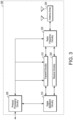
- FIG. 3 illustrates millimeter wave communication circuitry in accordance with some embodiments.
- Circuitry 300 is alternatively grouped according to functions. Components as shown in 300 are shown here for illustrative purposes and may include other components not shown here.
- Millimeter wave communication circuitry 300 may include protocol processing circuitry 305, which may implement one or more of medium access control (MAC), radio link control (RLC), packet data convergence protocol (PDCP), radio resource control (RRC) and non-access stratum (NAS) functions.
- Protocol processing circuitry 305 may include one or more processing cores (not shown) to execute instructions and one or more memory structures (not shown) to store program and data information.
- Millimeter wave communication circuitry 300 may further include digital baseband circuitry 310, which may implement physical layer (PHY) functions including one or more of hybrid automatic repeat request (HARQ) functions, scrambling and/or descrambling, coding and/or decoding, layer mapping and/or de-mapping, modulation symbol mapping, received symbol and/or bit metric determination, multi-antenna port pre-coding and/or decoding which may include one or more of space-time, space-frequency or spatial coding, reference signal generation and/or detection, preamble sequence generation and/or decoding, synchronization sequence generation and/or detection, control channel signal blind decoding, and other related functions.
- PHY physical layer
- HARQ hybrid automatic repeat request
- Millimeter wave communication circuitry 300 may further include transmit circuitry 315, receive circuitry 320 and/or antenna array circuitry 330.
- Millimeter wave communication circuitry 300 may further include radio frequency (RF) circuitry 325.
- RF circuitry 325 may include multiple parallel RF chains for one or more of transmit or receive functions, each connected to one or more antennas of the antenna array 330.
- protocol processing circuitry 305 may include one or more instances of control circuitry (not shown) to provide control functions for one or more of digital baseband circuitry 310, transmit circuitry 315, receive circuitry 320, and/or radio frequency circuitry 325.
- the transmit circuitry of may include one or more of digital to analog converters (DACs), analog baseband circuitry, up-conversion circuitry and filtering and amplification circuitry.
- DACs digital to analog converters
- the transmit circuitry may include digital transmit circuitry and output circuitry.
- the radio frequency circuitry may include one or more instances of radio chain circuitry, which in some aspects may include one or more filters, power amplifiers, low noise amplifiers, programmable phase shifters and power supplies.
- the radio frequency circuitry may include power combining and dividing circuitry in some aspects.
- the power combining and dividing circuitry may operate bidirectionally, such that the same physical circuitry may be configured to operate as a power divider when the device is transmitting, and as a power combiner when the device is receiving.
- the power combining and dividing circuitry may one or more include wholly or partially separate circuitries to perform power dividing when the device is transmitting and power combining when the device is receiving.
- the power combining and dividing circuitry may include passive circuitry comprising one or more two-way power divider/combiners arranged in a tree. In some aspects, the power combining and dividing circuitry may include active circuitry comprising amplifier circuits.
- the radio frequency circuitry may connect to transmit circuitry and receive circuitry via one or more radio chain interfaces or a combined radio chain interface.
- one or more radio chain interfaces may provide one or more interfaces to one or more receive or transmit signals, each associated with a single antenna structure which may comprise one or more antennas.
- the combined radio chain interface may provide a single interface to one or more receive or transmit signals, each associated with a group of antenna structures comprising one or more antennas.
- the receive circuitry may include one or more of parallel receive circuitry and/or one or more of combined receive circuitry.
- the one or more parallel receive circuitry and one or more combined receive circuitry may include one or more Intermediate Frequency (IF) down-conversion circuitry, IF processing circuitry, baseband down-conversion circuitry, baseband processing circuitry and analog-to-digital converter (ADC) circuitry.
- IF Intermediate Frequency
- the RF circuitry may include one or more of each of IF interface circuitry, filtering circuitry, upconversion and downconversion circuitry, synthesizer circuitry, filtering and amplification circuitry, power combining and dividing circuitry and radio chain circuitry.
- the baseband processor may contain one or more digital baseband systems.
- the one or more digital baseband subsystems may be coupled via an interconnect subsystem to one or more of a CPU subsystem, audio subsystem and interface subsystem
- the one or more digital baseband subsystems may be coupled via another interconnect subsystem to one or more of each of digital baseband interface and mixed-signal baseband sub-system.
- the interconnect subsystems may each include one or more of each of buses point-to-point connections and network-on-chip (NOC) structures.
- an audio sub-system may include one or more of digital signal processing circuitry, buffer memory, program memory, speech processing accelerator circuitry, data converter circuitry such as analog-to-digital and digital-to-analog converter circuitry, and analog circuitry including one or more of amplifiers and filters.
- a mixed signal baseband sub-system may include one or more of an IF interface, analog IF subsystem, downconverter and upconverter subsystem, analog baseband subsystem, data converter subsystem, synthesizer and control sub-system
- a baseband processing subsystem may include one or more of each of DSP sub-systems, interconnect sub-system, boot loader sub-system, shared memory sub-system, digital I/O sub-system, digital baseband interface sub-system and audio sub-system
- the baseband processing subsystem may include one or more of each of an accelerator subsystem, buffer memory, interconnect sub-system, audio sub-system, shared memory sub-system, digital I/O subsystem, controller sub-system and digital baseband interface sub-system.
- the boot loader sub-system may include digital logic circuitry configured to perform configuration of the program memory and running state associated with each of the one or more DSP sub-systems.
- the configuration of the program memory of each of the one or more DSP sub-systems may include loading executable program code from storage external to baseband processing sub-system.
- the configuration of the running state associated with each of the one or more DSP sub-systems may include one or more of the steps of setting the state of at least one DSP core which may be incorporated into each of the one or more DSP sub-systems to a state in which it is not running, and setting the state of at least one DSP core which may be incorporated into each of the one or more DSP sub-systems into a state in which it begins executing program code starting from a predefined memory location.
- the shared memory sub-system may include one or more of a read-only memory (ROM), static random access memory (SRAM), embedded dynamic random access memory (eDRAM) and non-volatile random access memory (NVRAM).
- the digital I/O subsystem may include one or more of serial interfaces such as I 2 C, SPI or other 1, 2 or 3-wire serial interfaces, parallel interfaces such as general-purpose input-output (GPIO), register access interfaces and direct memory access (DMA).
- a register access interface implemented in digital I/O subsystem may permit a microprocessor core external to baseband processing subsystem (1000 cross reference) to read and/or write one or more of control and data registers and memory.
- DMA logic circuitry implemented in digital I/O subsystem may permit transfer of contiguous blocks of data between memory locations including memory locations internal and external to baseband processing subsystem
- the digital baseband interface sub-system may provide for the transfer of digital baseband samples between the baseband processing subsystem and mixed signal baseband or radio-frequency circuitry external to the baseband processing subsystem
- the digital baseband samples transferred by the digital baseband interface sub-system may include in-phase and quadrature (I/Q) samples.
- the controller sub-system may include one or more of each of control and status registers and control state machines.
- the control and status registers may be accessed via a register interface and may provide for one or more of starting and stopping operation of control state machines, resetting control state machines to a default state, configuring optional processing features, configuring the generation of interrupts and reporting the status of operations.
- each of the one or more control state machines may control the sequence of operation of each of the one or more accelerator sub-systems.
- the DSP sub-system may include one or more of each of a DSP core sub-system, local memory, direct memory access sub-system, accelerator sub-system, external interface sub-system, power management unit and interconnect sub-system
- the local memory may include one or more of each of read-only memory, static random access memory or embedded dynamic random access memory.
- the direct memory access sub-system may provide registers and control state machine circuitry adapted to transfer blocks of data between memory locations including memory locations internal and external to the digital signal processor sub-system
- the external interface sub-system may provide for access by a microprocessor system external to DSP sub-system to one or more of memory, control registers and status registers which may be implemented in the DSP sub-system.
- the external interface sub-system may provide for transfer of data between local memory and storage external to the DSP sub-system under the control of one or more of the DMA sub-system and DSP core sub-system
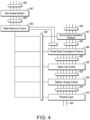
- FIG. 4 is an illustration of protocol functions in accordance with some embodiments.
- the protocol functions may be implemented in a wireless communication device according to some aspects.
- the protocol layers may include one or more of physical layer (PHY) 410, medium access control layer (MAC) 420, radio link control layer (RLC) 430, packet data convergence protocol layer (PDCP) 440, service data adaptation protocol (SDAP) layer 447, radio resource control layer (RRC) 455, and non-access stratum (NAS) layer 457, in addition to other higher layer functions not illustrated.
- PHY physical layer
- MAC medium access control layer
- RLC radio link control layer
- PDCP packet data convergence protocol layer
- SDAP service data adaptation protocol
- RRC radio resource control layer
- NAS non-access stratum
- the protocol layers may include one or more service access points that may provide communication between two or more protocol layers.
- the PHY 410 may transmit and receive physical layer signals 405 that may be received or transmitted respectively by one or more other communication devices.
- physical layer signals 405 may comprise one or more physical channels.
- an instance of PHY 410 may process requests from and provide indications to an instance of MAC 420 via one or more physical layer service access points (PHY-SAP) 415.
- PHY-SAP physical layer service access points
- requests and indications communicated via PHY-SAP 415 may comprise one or more transport channels.
- an instance of MAC 410 may process requests from and provide indications to an instance of RLC 430 via one or more medium access control service access points (MAC-SAP) 425.
- requests and indications communicated via MAC-SAP 425 may comprise one or more logical channels.
- an instance of RLC 430 may process requests from and provide indications to an instance of PDCP 440 via one or more radio link control service access points (RLC-SAP) 435.
- requests and indications communicated via RLC-SAP 435 may comprise one or more RLC channels.
- an instance of PDCP 440 may process requests from and provide indications to one or more of an instance of RRC 455 and one or more instances of SDAP 447 via one or more packet data convergence protocol service access points (PDCP-SAP) 445.
- requests and indications communicated via PDCP-SAP 445 may comprise one or more radio bearers.
- an instance of SDAP 447 may process requests from and provide indications to one or more higher layer protocol entities via one or more service data adaptation protocol service access points (SDAP-SAP) 449.
- SDAP-SAP service data adaptation protocol service access points
- requests and indications communicated via SDAP-SAP 449 may comprise one or more quality of service (QoS) flows.
- QoS quality of service
- RRC entity 455 may configure, via one or more management service access points (M-SAP), aspects of one or more protocol layers, which may include one or more instances of PHY 410, MAC 420, RLC 430, PDCP 440 and SDAP 447.
- M-SAP management service access points
- an instance of RRC 455 may process requests from and provide indications to one or more NAS entities via one or more RRC service access points (RRC-SAP) 456.
- RRC-SAP RRC service access points
- FIG. 5 is an illustration of protocol entities in accordance with some embodiments.
- the protocol entities may be implemented in wireless communication devices, including one or more of a user equipment (UE) 560, a base station, which may be termed an evolved node B (eNB), or new radio node B (gNB) 580, and a network function, which may be termed a mobility management entity (MME), or an access and mobility management function (AMF) 594, according to some aspects.
- UE user equipment
- eNB evolved node B
- gNB new radio node B
- MME mobility management entity
- AMF access and mobility management function
- gNB 580 may be implemented as one or more of a dedicated physical device such as a macro-cell, a femto-cell or other suitable device, or in an alternative aspect, may be implemented as one or more software entities running on server computers as part of a virtual network termed a cloud radio access network (CRAN).
- CRAN cloud radio access network
- one or more protocol entities that may be implemented in one or more of UE 560, gNB 580 and AMF 594 may be described as implementing all or part of a protocol stack in which the layers are considered to be ordered from lowest to highest in the order PHY, MAC, RLC, PDCP, RRC and NAS.
- one or more protocol entities that may be implemented in one or more of UE 560, gNB 580 and AMF 594 may communicate with a respective peer protocol entity that may be implemented on another device, using the services of respective lower layer protocol entities to perform such communication.
- UE PHY 572 and peer entity gNB PHY 590 may communicate using signals transmitted and received via a wireless medium.
- UE MAC 570 and peer entity gNB MAC 588 may communicate using the services provided respectively by UE PHY 572 and gNB PHY 590.
- UE RLC 568 and peer entity gNB RLC 586 may communicate using the services provided respectively by UE MAC 570 and gNB MAC 588.
- UE PDCP 566 and peer entity gNB PDCP 584 may communicate using the services provided respectively by UE RLC 568 and 5GNB RLC 586.
- UE RRC 564 and gNB RRC 582 may communicate using the services provided respectively by UE PDCP 566 and gNB PDCP 584.
- UE NAS 562 and AMF NAS 592 may communicate using the services provided respectively by UE RRC 564 and gNB RRC 582.
- the UE and gNB may communicate using a radio frame structure that has a predetermined duration and repeats in a periodic manner with a repetition interval equal to the predetermined duration.
- the radio frame may be divided into two or more subframes.
- subframes may be of predetermined duration which may be unequal.
- subframes may be of a duration which is determined dynamically and varies between subsequent repetitions of the radio frame.
- FDD frequency division duplexing
- the downlink radio frame structure is transmitted by a base station to one or devices, and uplink radio frame structure transmitted by a combination of one or more devices to a base station.
- the radio frame may have a duration of 10ms.
- the radio frame may be divided into slots each of duration 0.5 ms, and numbered from 0 to 19. Additionally, each pair of adjacent slots numbered 2i and 2i + 1, where i is an integer, may be referred to as a subframe.
- Each subframe may include a combination of one or more of downlink control information, downlink data information, uplink control information and uplink data information. The combination of information types and direction may be selected independently for each subframe.
- the downlink frame and uplink frame may have a duration of 10ms, and uplink frame may be transmitted with a timing advance with respect to downlink frame.
- the downlink frame and uplink frame may each be divided into two or more subframes, which may be 1ms in duration.
- each subframe may consist of one or more slots.
- the time intervals may be represented in units of T s .
- T s may be defined as 1 / (30,720 ⁇ 1000) seconds.
- a radio frame may be defined as having duration 30,720.T s
- a slot may be defined as having duration 15,360.T s .
- the number of slots may be determined based on a numerology parameter, which may be related to a frequency spacing between subcarriers of a multicarrier signal used for transmission.
- Constellation designs of a single carrier modulation scheme that may be transmitted or received may contain 2 points, known as binary phase shift keying (BPSK), 4 points, known as quadrature phase shift keying (QPSK), 16 points, known as quadrature amplitude modulation (QAM) with 16 points (16QAM or QAM16) or higher order modulation constellations, containing for example 64, 256 or 1024 points.
- the binary codes are assigned to the points of the constellation using a scheme such that nearest-neighbor points, that is, pairs of points separated from each other by the minimum Euclidian distance, have an assigned binary code differing by only one binary digit.
- the point assigned code 1000 has nearest neighbor points assigned codes 1001, 0000, 1100 and 1010, each of which differs from 1000 by only one bit.
- the constellation points may be arranged in a square grid, and may be arranged such that there is an equal distance on the in-phase and quadrature plane between each pair of nearest-neighbor constellation points.
- the constellation points may be chosen such that there is a pre-determined maximum distance from the origin of the in-phase and quadrature plane of any of the allowed constellation points, the maximum distance represented by a circle.
- the set of allowed constellation points may exclude those that would fall within square regions at the corners of a square grid.
- the constellation points are shown on orthogonal in-phase and quadrature axes, representing, respectively, amplitudes of sinusoids at the carrier frequency and separated in phase from one another by 90 degrees.
- the constellation points are grouped into two or more sets of constellation points, the points of each set being arranged to have an equal distance to the origin of the in-phase and quadrature plane, and lying on one of a set of circles centered on the origin.
- data may be input to an encoder to generate encoded data.
- the encoder may include a combination of one or more of error detecting, error correcting, rate matching, and interleaving.
- the encoder may further include a step of scrambling.
- encoded data may be input to a modulation mapper to generate complex valued modulation symbols.
- the modulation mapper may map groups containing one or more binary digits, selected from the encoded data, to complex valued modulation symbols according to one or more mapping tables.
- complex-valued modulation symbols may be input to the layer mapper to be mapped to one or more layer mapped modulation symbol streams.
- Layer mapping may be similarly represented for more than two layers.
- one or more streams of layer mapped symbols may be input to the precoder which generates one or more streams of precoded symbols. Representing the one or more streams of layer mapped symbols as a block of vectors: x 0 i ... x ⁇ ⁇ 1 i T where i represents a sequence number index in the range 0 to M symb layer ⁇ 1 the output is represented as a block of vectors: z 0 i ... z P ⁇ 1 i T where i represents a sequence number index in the range 0 to M symb ap ⁇ 1 .
- the precoding operation may be configured to include one of direct mapping using a single antenna port, transmit diversity using space-time block coding, or spatial multiplexing.
- each stream of precoded symbols may be input to a resource mapper which generates a stream of resource mapped symbols.
- the resource mapper may map precoded symbols to frequency domain subcarriers and time domain symbols according to a mapping which may include contiguous block mapping, randomized mapping or sparse mapping according to a mapping code.
- the resource mapped symbols may be input to multicarrier generator which generates a time domain baseband symbol.
- Multicarrier generator may generate time domain symbols using, for example, an inverse discrete Fourier transform (DFT), commonly implemented as an inverse fast Fourier transform (FFT) or a filter bank comprising one or more filters.
- DFT inverse discrete Fourier transform
- FFT inverse fast Fourier transform
- p T (t) is a prototype filter function
- T sym is the start time of the symbol period
- ⁇ k is a subcarrier dependent time offset
- f k is the frequency of subcarrier k.
- Prototype functions p T (t) may be, for example, rectangular time domain pulses, Gaussian time domain pulses or any other suitable function.
- a sub-component of a transmitted signal consisting of one subcarrier in the frequency domain and one symbol interval in the time domain may be termed a resource element.
- Resource elements may be depicted in a grid form.
- resource elements may be grouped into rectangular resource blocks consisting of 12 subcarriers in the frequency domain and the P symbols in the time domain, where P may correspond to the number of symbols contained in one slot, and may be 6, 7, or any other suitable number of symbols.
- resource elements may be grouped into resource blocks consisting of 12 subcarriers in the frequency domain and one symbol in the time domain.
- Each resource element 05 may be indexed as (k, l) where k is the index number of subcarrier, in the range 0 to N.M-1, where N is the number of subcarriers in a resource block, and M is the number of resource blocks spanning a component carrier in the frequency domain.
- coding of the signal to be transmitted may include one or more physical coding processes that may be used to provide coding for a physical channel that may encode data or control information. Coding may also include multiplexing and interleaving that generates combined coded information by combining information from one or more sources, which may include one of more of data information and control information, and which may have been encoded by one or more physical coding processes. The combined coded information may be input to a scrambler which may generate scrambled coded information.
- Physical coding process may include one or more of CRC attachment, code block segmentation, channel coding, rate matching and code block concatenation. An encoder that may be used to encode data according to one of a convolutional code and a tail-biting convolutional code.
- FIG. 6 is an illustration of a Media Access Control (MAC) entity in accordance with some embodiments.
- MAC entity 6100 may include one or more of a controller 6105, a logical channel prioritizing unit 6110, a channel multiplexer & de-multiplexer 6115, a PDU filter unit 6115, random access protocol entity 6120, data hybrid automatic repeat request protocol (HARQ) entity 6125 and broadcast HARQ entity 6130.
- controller 6105 may include one or more of a controller 6105, a logical channel prioritizing unit 6110, a channel multiplexer & de-multiplexer 6115, a PDU filter unit 6115, random access protocol entity 6120, data hybrid automatic repeat request protocol (HARQ) entity 6125 and broadcast HARQ entity 6130.
- HARQ data hybrid automatic repeat request protocol
- a higher layer may exchange control and status messages 6135 with controller 6105 via management service access point 6140.
- MAC service data units (SDU) corresponding to one or more logical channels 6145, 6155, 6165 and 6175 may be exchanged with MAC entity 6100 via one or more service access points (SAP) 6150, 6160, 6170 and 6180.
- PHY service data units (SDU) corresponding to one or more transport channels 6185, 6195, 61105 and 61115 may be exchanged with a physical layer entity via one or more service access points (SAP) 6190, 61100, 61110 and 61120.
- SAP service access points
- logical channel prioritization unit 6110 may perform prioritization amongst one or more logical channels 6145 and 6155, which may include storing parameters and state information corresponding to each of the one or more logical channels, that may be initialized when a logical channel is established.
- logical channel prioritization unit 6110 may be configured with a set of parameters for each of one or more logical channels 6145 and 6155, each set including parameters which may include one or more of a prioritized bit rate (PBR) and a bucket size duration (BSD).
- PBR prioritized bit rate
- BSD bucket size duration
- multiplexer & de-multiplexer 6115 may generate MAC PDUs, which may include one or more of MAC-SDUs or partial MAC-SDUs corresponding to one or more logical channels, a MAC header which may include one or more MAC sub-headers, one or more MAC control elements, and padding data.
- multiplexer & de-multiplexer 6115 may separate one or more MAC-SDUs or partial MAC-SDUs contained in a received MAC PDU, corresponding to one or more logical channels 6145 and 6155, and may indicate the one or more MAC-SDUs or partial MAC-SDUs to a higher layer via one or more service access points 6150 and 6160.
- HARQ entity 6125 and broadcast HARQ entity 6130 may include one or more parallel HARQ processes, each of which may be associated with a HARQ identifier, and which may be one of a receive or transmit HARQ process.
- a transmit HARQ process may generate a transport block (TB) to be encoded by the PHY according to a specified redundancy version (RV), by selecting a MAC-PDU for transmission.
- a transmit HARQ process that is included in a broadcast HARQ entity 6130 may retransmit a same TB in successive transmit intervals a predetermined number of times.
- a transmit HARQ process included in a HARQ entity 6125 may determine whether to retransmit a previously transmitted TB or to transmit a new TB at a transmit time based on whether a positive acknowledgement or a negative acknowledgement was received for a previous transmission.
- a receive HARQ process may be provided with encoded data corresponding to one or more received TBs and which may be associated with one or more of a new data indication (NDI) and a redundancy version (RV), and the receive HARQ process may determine whether each such received encoded data block corresponds to a retransmission of a previously received TB or a not previously received TB.
- a receive HARQ process may include a buffer, which may be implemented as a memory or other suitable storage device, and may be used to store data based on previously received data for a TB.
- a receive HARQ process may attempt to decode a TB, the decoding based on received data for the TB, and which may be additionally be based on the stored data based on previously received data for the TB.
- FIG. 7 illustrates an architecture of a system of a network in accordance with some embodiments.
- the system 700 is shown to include a user equipment (UE) 701 and a UE 702.
- the UEs 701 and 702 are illustrated as smartphones (e.g., handheld touchscreen mobile computing devices connectable to one or more cellular networks), but may also comprise any mobile or non-mobile computing device, such as Personal Data Assistants (PDAs), pagers, laptop computers, desktop computers, wireless handsets, or any computing device including a wireless communications interface.
- PDAs Personal Data Assistants
- pagers pagers
- laptop computers desktop computers
- wireless handsets wireless handsets
- any of the UEs 701 and 702 can comprise an Internet of Things (IoT) UE, which can comprise a network access layer designed for low-power IoT applications utilizing short-lived UE connections.
- An IoT UE can utilize technologies such as machine-to-machine (M2M) or MTC for exchanging data with an MTC server or device via a public land mobile network (PLMN), Proximity-Based Service (ProSe) or device-to-device (D2D) communication, sensor networks, or IoT networks.
- M2M or MTC exchange of data may be a machine-initiated exchange of data.
- An IoT network describes interconnecting IoT UEs, which may include uniquely identifiable embedded computing devices (within the Internet infrastructure), with short-lived connections.
- the IoT UEs may execute background applications (e.g., keep-alive messages, status updates, etc.) to facilitate the connections of the IoT network.
- the UEs 701 and 702 may be configured to connect, e.g., communicatively couple, with a radio access network (RAN) 710 - the RAN 710 may be, for example, an Evolved Universal Mobile Telecommunications System (UMTS) Terrestrial Radio Access Network (E-UTRAN), a NextGen RAN (NG RAN), or some other type of RAN.
- RAN radio access network
- UMTS Evolved Universal Mobile Telecommunications System
- E-UTRAN Evolved Universal Mobile Telecommunications System
- NG RAN NextGen RAN
- the UEs 701 and 702 utilize connections 703 and 704, respectively, each of which comprises a physical communications interface or layer (discussed in further detail below); in this example, the connections 703 and 704 are illustrated as an air interface to enable communicative coupling, and can be consistent with cellular communications protocols, such as a Global System for Mobile Communications (GSM) protocol, a code-division multiple access (CDMA) network protocol, a Push-to-Talk (PTT) protocol, a PTT over Cellular (POC) protocol, a Universal Mobile Telecommunications System (UMTS) protocol, a 3GPP Long Term Evolution (LTE) protocol, a 5G protocol, a New Radio (NR) protocol, and the like.
- GSM Global System for Mobile Communications
- CDMA code-division multiple access
- PTT Push-to-Talk
- POC PTT over Cellular
- UMTS Universal Mobile Telecommunications System
- LTE Long Term Evolution
- 5G protocol 5G protocol
- NR New Radio
- the UEs 701 and 702 may further directly exchange communication data via a ProSe interface 705.
- the ProSe interface 705 may alternatively be referred to as a sidelink interface comprising one or more logical channels, including but not limited to a Physical Sidelink Control Channel (PSCCH), a Physical Sidelink Shared Channel (PSSCH), a Physical Sidelink Discovery Channel (PSDCH), and a Physical Sidelink Broadcast Channel (PSBCH).
- PSCCH Physical Sidelink Control Channel
- PSSCH Physical Sidelink Shared Channel
- PSDCH Physical Sidelink Discovery Channel
- PSBCH Physical Sidelink Broadcast Channel
- the UE 702 is shown to be configured to access an access point (AP) 706 via connection 707.
- the connection 707 can comprise a local wireless connection, such as a connection consistent with any IEEE 802.11 protocol, wherein the AP 706 would comprise a wireless fidelity (WiFi) router.
- WiFi wireless fidelity
- the AP 706 is shown to be connected to the Internet without connecting to the core network of the wireless system (described in further detail below).
- the RAN 710 can include one or more access nodes that enable the connections 703 and 704.
- These access nodes can be referred to as base stations (BSs), NodeBs, evolved NodeBs (eNBs), next Generation NodeBs (gNBs), RAN nodes, and so forth, and can comprise ground stations (e.g., terrestrial access points) or satellite stations providing coverage within a geographic area (e.g., a cell).
- BSs base stations
- eNBs evolved NodeBs
- gNBs next Generation NodeBs
- RAN nodes and so forth, and can comprise ground stations (e.g., terrestrial access points) or satellite stations providing coverage within a geographic area (e.g., a cell).
- the RAN 710 may include one or more RAN nodes for providing macrocells, e.g., macro RAN node 711, and one or more RAN nodes for providing femtocells or picocells (e.g., cells having smaller coverage areas, smaller user capacity, or higher bandwidth compared to macrocells), e.g., low power (LP) RAN node 712.
- macro RAN node 711 e.g., macro RAN node 711
- femtocells or picocells e.g., cells having smaller coverage areas, smaller user capacity, or higher bandwidth compared to macrocells
- LP low power
- any of the RAN nodes 711 and 712 can terminate the air interface protocol and can be the first point of contact for the UEs 701 and 702.
- any of the RAN nodes 711 and 712 can fulfill various logical functions for the RAN 710 including, but not limited to, radio network controller (RNC) functions such as radio bearer management, uplink and downlink dynamic radio resource management and data packet scheduling, and mobility management.
- RNC radio network controller
- the UEs 701 and 702 can be configured to communicate using Orthogonal Frequency-Division Multiplexing (OFDM) communication signals with each other or with any of the RAN nodes 711 and 712 over a multicarrier communication channel in accordance various communication techniques, such as, but not limited to, an Orthogonal Frequency-Division Multiple Access (OFDMA) communication technique (e.g., for downlink communications) or a Single Carrier Frequency Division Multiple Access (SC-FDMA) communication technique (e.g., for uplink and ProSe or sidelink communications), although the scope of the embodiments is not limited in this respect.
- OFDM signals can comprise a plurality of orthogonal subcarriers.
- the physical downlink shared channel may carry user data and higher-layer signaling to the UEs 701 and 702.
- the physical downlink control channel (PDCCH) may carry information about the transport format and resource allocations related to the PDSCH channel, among other things. It may also inform the UEs 701 and 702 about the transport format, resource allocation, and H-ARQ (Hybrid Automatic Repeat Request) information related to the uplink shared channel.
- downlink scheduling (assigning control and shared channel resource blocks to the UE 702 within a cell) may be performed at any of the RAN nodes 711 and 712 based on channel quality information fed back from any of the UEs 701 and 702.
- the downlink resource assignment information may be sent on the PDCCH used for (e.g., assigned to) each of the UEs 701 and 702.
- Some embodiments may use concepts for resource allocation for control channel information that are an extension of the above-described concepts.
- some embodiments may utilize an enhanced physical downlink control channel (EPDCCH) that uses PDSCH resources for control information transmission.
- the EPDCCH may be transmitted using one or more enhanced the control channel elements (ECCEs). Similar to above, each ECCE may correspond to nine sets of four physical resource elements known as an enhanced resource element groups (EREGs). An ECCE may have other numbers of EREGs in some situations.
- a MTC PDCCH MPDCCH
- MPDCCH may be used for eMTC UEs.
- the RAN 710 is shown to be communicatively coupled to a core network (CN) 720 -via an S1 or NG interface 713.
- the CN 720 may be an evolved packet core (EPC) network, a 5GC network, or some other type of CN.
- EPC evolved packet core
- 5GC 5GC
- the S1 interface 713 is split into two parts: the S1-U interface 714, which carries traffic data between the RAN nodes 711 and 712 and the serving gateway (S-GW) 722, and the S1-mobility management entity (MME) interface 715, which is a signaling interface between the RAN nodes 711 and 712 and MMEs 721.
- S-GW serving gateway
- MME S1-mobility management entity
- the CN 720 comprises the MMEs 721, the S-GW 722, the Packet Data Network (PDN) Gateway (P-GW) 723, and a home subscriber server (HSS) 724.
- the MMEs 721 may be similar in function to the control plane of legacy Serving General Packet Radio Service (GPRS) Support Nodes (SGSN).
- the MMEs 721 may manage mobility aspects in access such as gateway selection and tracking area list management.
- the HSS 724 may comprise a database for network users, including subscription-related information to support the network entities' handling of communication sessions.
- the CN 720 may comprise one or several HSSs 724, depending on the number of mobile subscribers, on the capability of the equipment, on the organization of the network, etc.
- the HSS 724 can provide support for routing/roaming, authentication, authorization, naming/addressing resolution, location dependencies, etc.
- the S-GW 722 may terminate the S1 interface 713 towards the RAN 710, and routes data packets between the RAN 710 and the CN 720.
- the S-GW 722 may be a local mobility anchor point for inter-RAN node handovers and also may provide an anchor for inter-3GPP mobility. Other responsibilities may include lawful intercept, charging, and some policy enforcement.
- the P-GW 723 may terminate an SGi interface toward a PDN.
- the P-GW 723 may route data packets between the EPC network 723 and external networks such as a network including the application server 730 (alternatively referred to as application function (AF)) via an Internet Protocol (IP) interface 725.
- the application server 730 may be an element offering applications that use IP bearer resources with the core network (e.g., UMTS Packet Services (PS) domain, LTE PS data services, etc.).
- PS UMTS Packet Services
- LTE PS data services etc.
- the P-GW 723 is shown to be communicatively coupled to an application server 730 via an IP communications interface 725.
- the application server 730 can also be configured to support one or more communication services (e.g., Voice-over-Internet Protocol (VoIP) sessions, PTT sessions, group communication sessions, social networking services, etc.) for the UEs 701 and 702 via the CN 720.
- VoIP Voice-over-Internet Protocol
- PTT sessions PTT sessions
- group communication sessions social networking services, etc.
- the P-GW 723 may further be a node for policy enforcement and charging data collection.
- Policy and Charging Rules Function (PCRF) 726 is the policy and charging control element of the CN 720.
- PCRF Policy and Charging Rules Function
- HPLMN Home Public Land Mobile Network
- IP-CAN Internet Protocol Connectivity Access Network
- HPLMN Home Public Land Mobile Network
- V-PCRF Visited PCRF
- VPLMN Visited Public Land Mobile Network
- the PCRF 726 may be communicatively coupled to the application server 730 via the P-GW 723.
- the application server 730 may signal the PCRF 726 to indicate a new service flow and select the appropriate Quality of Service (QoS) and charging parameters.
- the PCRF 726 may provision this rule into a Policy and Charging Enforcement Function (PCEF) (not shown) with the appropriate traffic flow template (TFT) and QoS class of identifier (QCI), which commences the QoS and charging as specified by the application server 730.
- PCEF Policy and Charging Enforcement Function
- TFT traffic flow template
- QCI QoS class of identifier
- the components of FIG. 7 are able to read instructions from a machine-readable or computer-readable medium (e.g., a non-transitory machine-readable storage medium) and perform any one or more of the methodologies discussed herein.
- the processors e.g., a central processing unit (CPU), a reduced instruction set computing (RISC) processor, a complex instruction set computing (CISC) processor, a graphics processing unit (GPU), a digital signal processor (DSP) such as a baseband processor, an application specific integrated circuit (ASIC), a radio-frequency integrated circuit (RFIC), another processor, or any suitable combination thereof
- CPU central processing unit
- RISC reduced instruction set computing
- CISC complex instruction set computing
- GPU graphics processing unit
- DSP digital signal processor
- ASIC application specific integrated circuit
- RFIC radio-frequency integrated circuit
- Instructions may comprise software, a program, an application, an applet, an app, or other executable code for causing at least any of the processors to perform any one or more of the methodologies discussed herein.
- the instructions may reside, completely or partially, within at least one of the processors (e.g., within the processor's cache memory), the memory/storage devices, or any suitable combination thereof.
- the instructions may reside on a tangible, non-volatile communication device readable medium, which may include a single medium or multiple media.
- any portion of the instructions may be transferred to the hardware resources from any combination of the peripheral devices or the databases 706. Accordingly, the memory of processors, the memory/storage devices, the peripheral devices, and the databases are examples of computer-readable and machine-readable media.
- MTC is a promising and emerging technology that may include applications such as smart metering, healthcare monitoring, remote security surveillance, and an intelligent transportation system. These services and applications may stimulate the design and development of a new type of UE whose seamless integration into current and next generation mobile broadband networks such as LTE and LTE-Advanced is desirable.
- MTC- and IoT-specific designs are being developed, with the primary objectives focusing on lower device cost, enhanced coverage and reduced power consumption.
- the transmission bandwidth for both control and data channels has been reduced to 1 PRB
- Rel-13 eMTC transmission bandwidth for both control and data channels has been reduced to 1.4 MHz.
- the transmission bandwidth of data channels may be increased to 5 MHz for Rel-14 feMTC UEs, which may create additional varied issues in communications.
- time domain repetitions have been adopted as the technique for coverage enhancement.
- the supported repetitions for PUSCH/NPUSCH may be limited to certain values, i.e., ⁇ 1, 2, 4, 8, 16, 32, 64, 128, 192, 256, 384, 512, 768, 1024, 1536, 2048 ⁇ for Physical Uplink Shared Channel (PUSCH) transmissions and ⁇ 1, 2, 4, 8, 16, 32, 64, 128 ⁇ for narrowband PUSCH (NPUSCH) transmissions.
- PUSCH Physical Uplink Shared Channel
- NPUSCH narrowband PUSCH
- the actual coverage of the MTC UE may correspond to somewhere in between two aforementioned repetition levels. This may be problematic as scheduling a PUSCH transmission with a higher RL may result in unnecessary UL transmissions and increase UE power consumption, which may be of concern especially for devices with limited battery life and/or in locations that are difficult to access.
- an initial transmission may be configured with fewer number of repetitions, and additional retransmissions may be scheduled to achieve a target Block Error Rate (BLER) and coverage.
- BLER Block Error Rate
- such a retransmission schedule may prolong the latency of the communications and decay on-time performance.
- the receiver may be able to successfully decode the transmitted transport blocks with fewer number of repeated transmissions for the initial or retransmission than the scheduled number of repetitions. This may occur because the scheduled number of repetitions may be originally intended based on long-term channel conditions or a coverage level for the particular UE for a given physical channel, while the instantaneous channel conditions may be different.
- an early termination signal may be applied.
- the use of the ETS may permit the UE to terminate repeated transmissions of the initial transmission or retransmission before the number of repetitions originally scheduled by the eNB/gNB (referred to below simply as the eNB for convenience). It would be beneficial for UEs to avoid excess number of repetitions and reduce UE power consumption by designing the configuration and applicability, physical design and resource allocation of the ETS.
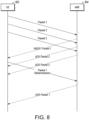
- FIG. 8 illustrates a HARQ process in accordance with some embodiments.
- the UE 802 and eNB 804 may be shown in FIGS. 1-7 . Although the UE 802 is shown as the transmitter and the eNB 804 the receiver (UL transmission), the same process may be applied for a DL transmission.
- the UE 802 may transmit several packets. As shown, the eNB 804 responds to the UE 802 with either a successful reception (ACK) or unsuccessful reception (NACK) transmission to indicate whether or not the particular packet was successfully received. The UE 802 may repeat transmission to the eNB 804 of any packets for which a NACK was received, up to a predetermined number of repetitions or an ACK is received from the eNB 804. As multiple packets may be transmitted by the UE 802 prior to HARQ feedback being received, the HARQ feedback may indicate which packet is being responded to.
- ACK successful reception
- NACK unsuccessful reception
- the UE 802 may repeat transmission to the eNB 804 of any packets for which a NACK was received, up to a predetermined number of repetitions or an ACK is received from the eNB 804. As multiple packets may be transmitted by the UE 802 prior to HARQ feedback being received, the HARQ feedback may indicate which packet is being responded to.
- the HARQ process may be either chase combining, in which the same packet is sent (and stored in a buffer) to build up the signal characteristics, or incremental redundancy, in which a portion of the data in the packet changes.
- the packet may contain data, error detection bits and Forward Error Correction bits (FEC).
- FEC Forward Error Correction bits
- the HARQ transmissions may be synchronous, where the receiver has knowledge of the packet to arrive (the HARQ number and RV), or asynchronous, where the transmitter provides details about which HARQ process is being used.
- the retransmissions may be adaptive, where the transmission attributes may change among the retransmissions but are notified by the transmitter, or non-adaptive in which the transmission characteristics remain the same during each retransmission.
- the UE signals the capability to support ETS.
- the UE transmits ETS support in capability information.
- the capability information is provided during RRC connection establishment.
- message 3 (contention resolution) in the initial random access (RACH) procedure before RRC establishment may not support ETS.
- the network may have stored the UE capabilities, allowing ETS to be used during the RACH procedure.
- Message 3 may be addressed towards a TMSI value or Random number but contains a new cell Radio Network Temporary Identifier (C-RNTI) which will be used for further communication between the UE and the eNB.
- C-RNTI Radio Network Temporary Identifier
- ETS is supported only in certain coverage conditions, e.g. deep coverage such as CE mode B.
- both CE mode A and CE mode B may support ETS.
- the supported cases for ETS and the HARQ-ACK feedback for early termination of MTC Physical Downlink Control Channel (MPDCCH) monitoring in case of PUSCH transmissions confirming the reception of the RRC Connection Release message can be different.
- MPDCCH Physical Downlink Control Channel
- only CE mode B may support ETS, while both CE mode A and CE mode B can support HARQ-ACK feedback for early termination of MPDCCH monitoring for PUSCH transmissions confirming the reception of the RRC Connection Release message.
- both ETS and the HARQ-ACK feedback for early termination of MPDCCH monitoring for PUSCH transmissions confirming the reception of the RRC Connection Release message may be supported.
- the eNB may enable the ETS semi-statically via higher layer signaling.
- the configuration can be cell-specific.
- the configuration may be UE-specific.
- R may vary dependent on the bandwidth used by the UE, channel conditions, or other variables.
- ETS may be configured to be enabled for PUSCH retransmission by higher layer signaling.
- ETS may be used for retransmission only when the number of scheduled repetitions for the retransmission is larger than a predetermined amount R1, where R1 can be a positive integer and can be different from R in the above embodiment.
- R1 can be 32, 64, 128 or 256, which can be smaller than R.
- the UE may stop monitoring the control channel or enters light sleep mode until the subframe in which the last repetition of PUSCH was originally scheduled.
- the UE may keep monitoring the search space as configured after reception of the ETS.
- the eNB can schedule a PDSCH/PUSCH transmission after the termination of PUSCH transmission before the last repetition of the PUSCH transmission originally scheduled.
- the ETS physical design may take various embodiments. These embodiments may include ETS physical designs that are MPDCCH-based, Physical Hybrid-ARQ Indicator Channel (PHICH)-based, and/or sequence-based.
- PHICH Physical Hybrid-ARQ Indicator Channel
- the ETS can be based on existing downlink control information (DCI) formats, DCI format 6-0A or DCI format 6-0B.
- DCI downlink control information
- DCI format 6-0A a mechanism may be used that is similar to semi-persistent scheduling (SPS) validation.
- SPS semi-persistent scheduling
- one or more fields in the DCI can be set to predefined default values for validation of the reception of the ETS. These fields may include the cyclic redundancy code (CRC), which may be scrambled using the C-RNTI or alternatively, a group-RNTI can be defined and used.
- DCI format 6-0A may include a Transmit Power Control (TPC) field set to '00' (DCI format 6-0B does not include a TPC field).
- TPC Transmit Power Control
- the resource block assignment field may be set to all '1's.
- the redundancy version (RV) field may be set to '00.'
- the Modulation and Coding Scheme (MCS) field may be set to all '1's.
- the Channel State Information (CSI) request field if present, may be set to '0'.
- the repetition number (for PUSCH) field may be set to all '0's.
- the New Data Indicator (NDI) field which indicates whether the transmission is a new transmission or retransmission, may be set to '0'.
- the frequency hopping flag field if present, may be set to '0'. Note that in various embodiments, some of the above fields may be used as validation bits and different default values may be used. Note further that the default values above are merely examples - other values may be used in other embodiments.
- the MPDCCH payloads are the same for the explicit HARQ-ACK for termination of MPDCCH monitoring and for the explicit HARQ-ACK for termination of a PUSCH transmission.
- the UE may be able to determine whether the UE is to go to sleep based on the contents of latest (maybe the on-going) PUSCH transmission. For example, if the latest PUSCH transmission is for confirming the reception of an RRC Connection Release message, once the UE receives the explicit ACK feedback for the PUSCH transmission, the UE may be able to enter sleep mode.
- the MPDCCH payload of the explicit HARQ-ACK for termination of MPDCCH monitoring and for termination of a PUSCH transmission can be different This may be determined by the UE through the use of different default values for certain fields.
- the least significant bit (LSB) 5 bits in the resource block assignment field can be set to all '1's to indicate the termination of MPDCCH monitoring and can be set to '11110' to indicate the termination of a PUSCH transmission, or vice versa.
- the 4-bit MCS field can be set to all '1's to indicate the termination of MPDCCH monitoring and can be set to '1110' to indicate the termination of a PUSCH transmission, or vice versa. Note that the use of other default values in addition or instead of the above are not precluded.
- the HARQ process number field can be reused to indicate to which HARQ process the ETS is related.
- the HARQ process number field plus additional bits (which may be reused from other fields and the number of validation bits reduced) can be used as a bitmap for all HARQ processes. For example, in CE mode A, 8 bits can be used to indicate which PUSCH TB has been successfully received, while in CE mode B, 2 bits can be enough as there are only 2 HARQ processes supported in CE mode B.
- the ACK/NACK information can be jointly encoded with another field in the DCI.
- the ACK/NACK information may be jointly encoded with the HARQ process number.
- the MSB or LSB of HARQ process number field, or alternatively other fields, can be used to indicate the ACK/NACK of an on-going PUSCH transmission or the latest PUSCH transmission if there is no on-going PUSCH transmission.
- a new DCI format can be defined for ETS.
- the DCI can be a more compact DCI than the existing DCIs (e.g., DCI format 6-0A or 6-0B) to reduce the number of repetitions needed to achieve certain coverage.
- the size of the new DCI may be 2 bits (plus the CRC bits), if ETS is supported only in CE mode B. More generally, the size of the new DCI may be N bits plus M CRC bits.
- the N bits can be used for indication of an ACK/NACK for N HARQ processes, or can be used to indicate a HARQ-ACK response for a HARQ process and/or the repetitions numbers after this ETS to be transmitted by the UE.
- the field of the number of repetitions can be ignored if the indication of the HARQ-ACK feedback is ACK.
- a 16-bit CRC can be used.
- the number of CRC bits can be reduced, e.g. to 8 bits.
- 8 out of 16 bits in the C-RNTI can be used to scramble the CRC.
- a group-RNTI can be defined to enable the eNB to respond to a several UEs at the same time. In this case, the eNB should ensure there is no confusion among the UEs, i.e. feedback is supplied on different resources for UEs with the same 8 bits from the C-RNTIs.
- the UE may increase blind detections to decode the DCI.
- the UE may monitor both the existing MPDCCH transmission and the new DCI format. This may result an increase in the UE complexity.
- the new DCI may be limited, for example, with 2 bits in the new DCI as the bitmap for HARQ-ACK feedback, the UE may have a priori knowledge that the DCI content may consist of only 4 possible states. Thus, the UE may merely perform a correlation-based detection procedure, with 4 hypothesis tests, for the new DCI detection. This complexity is quite low compared to regular DCI decoding.
- ETS may be used only when the HARQ-ACK response is an ACK
- 1 bit can be used to indicate one out of two HARQ processes that has been successfully received, or 2 bits can be used to indicate which of two processes have been successfully received.
- N bits can be used as validation bits. These bits may be used in additional to the CRC bits.
- the presence of the ETS may indicate the ACK of an ongoing PUSCH transmission.
- the eNB may not send the ETS.
- the eNB may instead merely send a UL grant.
- the UE may consider the UL grant as the termination of the ongoing PUSCH transmission and instead start a new transmission based on the new UL grant.
- the UE may avoid simultaneously monitoring the existing DCI formats and the new DCI format.
- the UE may not be expected to monitor for DCI formats scheduling PDSCH or PUSCH transmissions (e.g., DCI formats 6-1B/0B) in the subframes when the UE is expected to monitor for the ETS.
- the UE complexity is kept low at the cost of limiting the scheduling flexibility.
- the MPDCCH search space and the DL narrowband (NB) monitored for the ETS may be different from the DL NB monitored for UE-specific shared space (USS) monitoring.
- NB DL narrowband
- USS UE-specific shared space
- the existing UL gaps may be reused, the existing gaps may be lengthened, or additional UL gaps may be created.
- the UE may only be expected to monitor for the ETS and not for DCI formats 6-1B/0B.
- the search space of the ETS can be overlapped with one or more other USS and/or common search space (CSS).
- the priority regarding which search space to be monitored by the UE can be predefined or configured by the eNB, e.g. via RRC signaling.
- the entire search space with lower priority that overlaps with a search space with higher priority may be dropped.
- only the MPDCCH candidates in the lower priority search space which occupies a part of the search space with higher priority may be dropped.
- the UE can still monitor the MPDCCH transmitted on the USS/CSS that overlaps with search space for ETS by skipping the MPDCCH candidates that overlap with the ETS search space.
- the search space for the ETS can be configured with relatively small occasions and thus may result in limited impact in scheduling flexibility.
- the search space with lower priority may be deferred on the subframes configured for monitoring of the search space with higher priority.
- the MPDCCH candidates that overlap with the ETS search space can be deferred after the ETS search space.
- the parameter G configured for USS/CSS can also be set to a larger value that takes into account the impact from the ETS search space.
- certain candidates in the USS/CSS can be skipped if the USS/CSS overlaps with the ETS search space.
- the blind detection trials for the ETS can be reduced, e.g. by selecting certain combinations, e.g. only N PRBs with a subset of ⁇ R ETS , R ETS /2, R ETS /4, R ETS /8 ⁇ .
- the blind detection attempts for other USS/CSS can be limited to a subset of original blind detection attempts, and these candidates can still be blindly detected on the ETS monitoring occasions, as long as the total number of blind detections can be kept the same.
- ETS blind detection attempts can be defined as ⁇ 24, R, 1 ⁇ , where R can be ⁇ R ETS , R ETS /2, R ETS /4, R ETS /8 ⁇ .
- R can be ⁇ R ETS , R ETS /2, R ETS /4, R ETS /8 ⁇ .
- candidates in other USS/CSS can be [ ⁇ 2,R1,1 ⁇ 4,R1,1 ⁇ ], [ ⁇ 4,R2,1 ⁇ 8,R2,1 ⁇ ], [ ⁇ 8,R1,2 ⁇ 16,R1,1 ⁇ ], [ ⁇ 8,R2,2) ⁇ 16,R2,1 ⁇ ], [ ⁇ 8,R3,1 ⁇ 16,R3,1 ⁇ ], where R1, R2, R3 and R4 depends on Rmax of the search space.
- Other combination of blind detection trials for ETS and other USS/CSS are not precluded.
- the UE can assume that all the 6 PRBs in the NB with distributed transmission is always used for ETS.
- the ETS can be UE-specific if a C-RNTI is used. In another embodiment, the ETS can be group-specific if a group-RNTI is introduced. In addition, the ETS in some embodiments may be transmitted only when the ETS is an ACK Alternatively, the ETS can be always transmitted (regardless of ACK or NACK), and the information carried by the ETS would indicate whether the transmission is an ACK or NACK Similar embodiments may be used for feNB-IoT UEs; 1 bit or just the CRC may be sufficient for UEs configured with 1 HARQ process. On the other hand, for UEs configured with 2 HARQ processes, 2 bits can be used - similar to the CE mode B in the efeMTC design.
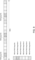
- the PHICH can be reused and/or extended for the ETS. Recall that the PHICH is spread across the whole system BW in legacy LTE. For BL UEs, a bandwidth-limited PHICH with coverage enhancement may be used.
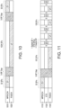
- FIG. 9 illustrates a bandwidth limited Physical Hybrid-ARQ Indicator Channel (PHICH) in accordance with some embodiments.
- the PHICH group 900 can be mapped to each NB as illustrated in FIG. 9 .
- 1 REG may consist of 4 resource elements (REs). Note that when the PHICH is transmitted on the symbols carrying the cell reference signal, primary synchronization signal, or secondary synchronization signal (CRS/PSS/SSS), the PHICH can be punctured on, or rate matched around, the REs.
- the PHICH may be power boosted (e.g., by increasing the number of REs used).
- frequency domain enhancement may be used.
- a new virtual PHICH group, corresponding to multiple PHICH groups in existing LTE can be defined.
- the REs allocated for these existing multiple PHICH groups can be used for the new introduced PHICH group.
- the PHICH groups #6n and #6n+3 shown in FIG. 9 can be allocated together for one PHICH transmission.
- a new rate matching, mapping the PHICH symbols to the increased REs can be used.
- the PHICH transmission can be repeated, with each repetition mapped to one existing PHICH group.
- the PHICH can also be spread with a longer sequence to be mapped to increased REs. The longer sequence can still be based on the demodulation reference signal (DMRS) sequence.
- DMRS demodulation reference signal
- time domain repetition may be used.
- the PHICH transmission may be transmitted in only one symbol in a subframe, and can be repeated across subframes.
- the PDSCH transmission can be rate matched around this symbol, or may be punctured.
- the PHICH transmission may be repeated in multiple symbols within a subframe. For example, the PHICH transmission can be transmitted on the last 11 symbols within a subframe, where the first 3 symbols are not used for coexistence with legacy control region. On top of this, additional repetitions across subframes can be used for further coverage enhancement
- the PHICH transmission within 1 PRB can be designed. For example, only 1 PHICH group occupying the PRB may be introduced. In this case, frequency domain enhancement may not be supported, while power boosting and time domain repetitions can still be applied.
- Orthogonal sequences can be applied to the PHICH transmission to enable UE multiplexing. For example, following LTE, up to 8 orthogonal sequence can be applied to one PHICH group in one OFDM symbol.
- a time domain orthogonal cover code such as a Hadamard code or DFT code can be used as well for PHICH multiplexing.
- a length-11 OCC can be used to multiplex up to 8*11 PHICHs.
- the orthogonal sequence and time domain OCC to be used can be configured by the eNB, e.g. via RRC signaling.
- a mapping from UE/PUSCH to the associated PHICH can be defined, which is elaborated below.
- the ETS may be sequence-based.
- the sequence can be any constant amplitude zero autocorrelation (CAZAC) sequence, e.g., a Zadoff-Chu (ZC) sequence.
- CAZAC constant amplitude zero autocorrelation
- ZC Zadoff-Chu
- NPSS/NSSS narrowband PSS/SSS
- PSS or DMRS sequences can be used.
- a ZC sequence with a root index different from existing root indexes used for NPSS/NSSS/PSS may be used.
- the DMRS root index and CS/OCC can be based on the cell ID and/or UE ID.
- Time-domain resources may include monitoring instances for the ETS.
- the monitoring instances may be configured to be periodic, possibly with an offset.
- the periodicity and/or offset can be predefined, or configured via RRC signaling, similar to the search space starting subframe configuration for existing USS.
- the value of periodicity and/or offset can be cell-specific or UE-specific.
- a time window may be applied on top of a periodic ETS transmission, where the ETS is transmitted only within the window.
- the window can be configured (e.g., via RRC signaling) or predefined, and the value can depend on the repetition level (RL) of the PUSCH transmission.
- a specific timing relationship may exist between the first PUSCH subframe and the corresponding ETS.
- the first ETS for a certain PUSCH can be transmitted X subframes after the start of the PUSCH transmission.
- the following ETS transmission opportunity can be between every P PUSCH transmission subframes after X ms from the start of the PUSCH transmission, where P is the configured periodicity of ETS monitoring occasions.
- the ETS monitoring occasion can be X+nP, taking into account the switching subframes (for a HD-FDD UE) and ETS durations, i.e. ETS monitoring occasion can be between every (P - 2 - ETS duration) PUSCH subframes for HD-FDD transmission.
- the ETS monitoring occasion is defined as every P ms (e.g., P may be specified as 256) of UL transmissions (which may include non-BL/CE UL subframes).
- the ETS duration can be the number of repetitions used for a single ETS transmission.
- the ETS duration can be larger, e.g. to incorporate multiple ETS transmissions to provide flexibility at the eNB side.
- the ETS duration can be predefined or configured by RRC signaling.
- the ETS duration can be the same as the UL compensation gap, i.e., 40ms.
- n can depend on the coverage level of the UE, e.g. depending on the number of PUSCH repetitions, or PRACH coverage level, or Rmax in USS.
- the X, P, and/or maximum value of n can be predefined or configured by RRC signaling.
- n can be ⁇ 0, 1, ..., ceil((R-X+Y)/P) ⁇ , where R is the smallest supported number of PUSCH repetitions used for the UE to achieve a target Maximum Coupling Loss (MCL) at a target Block Error Rate (BLER) with initial transmission.
- MCL Maximum Coupling Loss
- BLER Block Error Rate
- R is the number of repetitions indicated by the UL grant for the initial transmission scheduling.
- X is larger than the number of scheduled PUSCH repetitions, this may imply that ETS is not used for this PUSCH transmission.
- Y can be a predefined parameter or may be dependent on the UE coverage level, e.g. a function of number of PUSCH repetitions or Rmax.
- Y can be configured by RRC signaling.
- Y can be set to no more than the drx-ULRetransmissionTimer if cDRX is configured. This may be useful for use by a PUSCH transmission to confirm the reception of RRC connection release message.
- the ETS monitoring occasions may occur at every P PUSCH transmission subframe starting from X ms after the start of the PUSCH transmission, and ending by Y ms after the end of the PUSCH transmission. Note that as long as a UE receives an ACK from the eNB, the remaining ETS monitoring occasions may be skipped by the UE.
- X and P can be R/f
- n can be from ⁇ 0, 1, ..., f-1 or ceil((R-X+Y)/P) ⁇ , where f is a positive integer, which can be predefined or configured by the eNB, e.g. via RRC signaling.
- X and P can be R/4, and n can be from ⁇ 0, 1, ..., 5 ⁇ .
- X can be R/2 and P can be R/4.
- FIGS. 10 and 11 illustrate a PUSCH transmission without and with, respectively, an ETS in accordance with some embodiments.
- the PUSCH transmission in FIGS. 10 and 11 may assume R is 1024.
- the DCI may schedule 1024 repetitions.
- the MPDCCH transmission 1010 may indicate the DCI in 24 subframes.
- the PUSCH transmission 1020 may be 1024 subframes long. After the PUSCH transmission 1020, another 3 subframe gap may be provided prior to the next MPDCCH 1010.
- the X can be 512 and P can be 128 PUSCH transmitting subframes or 128+2+ETS duration (if the PUSCH transmission, switching subframes and ETS subframes are taken into account).
- the signals in FIG. 11 may be similar to those of FIG. 10 .
- the MPDCCH transmission 1110 be 24 subframes and may be followed by a 3 subframe gap.
- the initial PUSCH transmission 1120 may, however, only be 512 subframes long before monitoring for an ETS 1130.
- the UE may switch to the subcarriers on which the ETS 1130 is carried, monitor these subcarriers for one or more subframes, and then switch back to transmit the PUSCH transmission 1120 if no ETS is found or if the ETS indicates a NACK.
- the switching may take one or more subframes.
- the UE may then transmit further repetitions of the PUSCH transmission 1120 for a shorter number of subframes (shown in FIG. 11 as 128 subframes) than the initial set of PUSCH transmissions before again checking the ETS 1130. This may be repeated until an ETS is received or the PUSCH transmissions reach the predetermined number.
- the number of subframes after the initial set of PUSCH transmissions may be constant, as shown, or may vary - for example getting smaller with an increase in total number of PUSCH transmissions or with channel conditions.
- the ETS should be correctly associated with a corresponding PUSCH transmission. This can be achieved by using a specific timing relationship associated with each PUSCH transmission, which may provide an implicit indication of the HARQ process ID with which the ETS is associated.
- the ETS does not include an explicit indication of HARQ process ID, e.g. a PHICH-like ETS.
- HARQ process ID may be explicitly indicated. This is to say that an ETS may be transmitted that is based on MPDCCH with HARQ process ID or bitmap for all HARQ processes can be used.
- the constraints on the starting subframe of the search space may still apply to the ETS.
- the periodic transmission above can be extended to a "pseudo periodic" behavior, where within each periodicity, the ETS may start on the next available starting subframe of the search space.
- the repetitions can be semi-statically configured by higher layer signaling. In another embodiment, the repetitions can be determined based on the coverage level (e.g., PRACH coverage level, PUSCH RLs, R max for the MPDCCH, or the number of DCI repetitions used to carry the UL grant) of the UE.
- the coverage level e.g., PRACH coverage level, PUSCH RLs, R max for the MPDCCH, or the number of DCI repetitions used to carry the UL grant
- a predefined mapping from the PRACH coverage level to ETS RLs can be used, e.g., the PRACH coverage level ⁇ 0, 1, 2, 3 ⁇ can be mapped to ETS RLs ⁇ R max_ETS /4, R max_ETS /2, R max_ETS /4*3, R max_ETS ⁇ , respectively, where R max_ETS can be the same as R max for other existing MPDCCH, or a predefined value, or indicated via higher layer signaling.
- the search space candidates can reuse the same design for MPDCCH in Rel-13 eMTC, where the search space candidates are based on R max_ETS and the aggregation level for the DCI based ETS.
- the configured periodicity should be large enough to allow repetitions to fit into one periodicity.
- the introduction of the ETS may have a timing impact for HD-FDD as gaps for reception of the ETS may be provided between the PUSCH repetitions.
- FD-FDD full duplex FDD
- the gap can be indicated by eNB via bitmap, e.g. marked as invalid UL subframes.
- the gap may be based on the ETS configuration. For example, the duration that starts from 1 subframe before an ETS transmission opportunity and ends at 1 subframe after the ETS transmission opportunity may be the gap where no UL transmission is allowed.
- the ETS may be monitored during the UL compensation gaps that may be configured for more than 256 ms of UL transmissions when the UE is in CE mode B.
- the UE may monitor both the ETS and one or more other MPDCCH transmissions simultaneously.
- the ETS can be transmitted in the same search space as the configured USS, where ETS monitoring occasions can be further restricted as discussed above with predetermined periodicity, offset and/or within a window.
- a separate search space can be defined for the ETS.
- the UE may not simultaneously monitor the ETS and another USS/CSS. Specifically, during the ETS monitoring occasions, the UE may not monitor other search spaces. Alternatively, the UE can monitor other search spaces, with reduced blind decoding attempts for a MPDCCH transmission transmitted in the other search spaces.
- the search space for the ETS can be defined in terms of periodicity, offset, window length during which the ETS may be transmitted, and/or the starting/ending time of the search space with respect to e.g. the starting/ending position of the PUSCH transmission.
- a single or small number of candidate(s) can be defined in a separate UE-specific or common search space or shared within the USS that the UE is expected to monitor according to the configuration of monitoring occasions. This can limit the impact from increased blind decoding attempts by only increasing the number of total blind decoding candidates by only one or few additional blind decoding candidate(s).
- An additional HARQ-ACK feedback monitoring occasion may be added to further support the ETS together with the HARQ-ACK feedback for early termination of MPDCCH monitoring for PUSCH transmissions confirming the reception of a RRC Connection Release message.
- the additional HARQ-ACK feedback monitoring occasion can be configured after the end of scheduled PUSCH repetitions, e.g. in terms of offset with respect to the end of scheduled PUSCH repetition and a window length for the monitoring occasion duration.
- the offset and window length can be predefined (e.g. specified in the spec) or may be configured by RRC signaling (e.g. as a part of ETS configuration, or as a separate configuration).
- frequency domain resources may be considered.
- the frequency domain resource may be indicated by the eNB semi-statically.
- an NB index may be indicated in the RRC configuration for the ETS.
- the frequency domain resource may be the same as the NB where the UE monitors for a MPDCCH transmission.
- the frequency resource can be the same as the corresponding PUSCH transmission (e.g. in TDD systems).
- the detailed resource allocation within a NB can be determined by a variety of methods, which may differ dependent on the ETS design. For example, for a MPDCCH-based design, in one embodiment, all 6 PRBs may be allocated by default for the ETS. In another embodiment, N (less than 6) PRBs may be allocated for the ETS.
- the number of PRBs allocated for the ETS can be predefined/configured by the eNB and/or can be based on the coverage level (e.g., based on the PRACH coverage level, PUSCH RLs or Rmax for MPDCCH) of the UE. For example, the number of PRBs for PRACH coverage level ⁇ 0, 1, 2, 3 ⁇ can be predefined to ⁇ 1, 3, 4, 6 ⁇ , respectively.
- the set of PRBs allocated for the ETS can be predefined to the lowest N PRBs or the highest N PRBs.
- the eNB may signal the PRB indexes (to be used) or, for example, indicate if the PRBs to be used are the lowest or highest N PRBs.
- a mapping from PUSCH resource to the PRB indexes can be defined, as elaborated below.
- PHICH-based design in one embodiment, only 1 PHICH group corresponding to 12 REs may be used for the ETS.
- the group index can be indicated by the eNB, e.g. via RRC signaling.
- a mapping from the PUSCH PRBs to the PHICH group can be defined.
- the PHICH group index can also depend on the UE ID, e.g. determined by mod(C-RNTI + PUSCH resource index, number of PHICH groups).
- multiple PHICH groups can be used for the ETS.
- the number of PHICH groups, denoted by N, can be indicated by the eNB, e.g. via RRC signaling.
- the number of PHICH groups can be based on coverage level (e.g. PRACH coverage level, RLs of PUSCH, or Rmax for MPDCCH) of the UE.
- coverage level e.g. PRACH coverage level, RLs of PUSCH, or Rmax for MPDCCH
- the number of PHICH groups for PRACH coverage level ⁇ 0, 1, 2, 3 ⁇ can be predefined to ⁇ 1, 3, 4, 6 ⁇ , respectively.
- the set of PHICH groups can be predefined to the lowest or highest N PHICH groups.
- the eNB may signal the PHICH group indexes or indicate if the lowest or highest N PHICH group is indicated.
- a mapping from PUSCH resource to the PHICH group indexes can be defined, as elaborated below.
- the DMRS sequence used for a PHICH-based ETS can be configured by the eNB for each UE.
- the DMRS sequence may be associated with the UE ID, e.g. UE ID mod 8.
- n seq ⁇ ETS I RA UL + n DMRS + n ID mod n spreading ⁇ ETS , where
- the index may be denoted by X and the number of PRBs/PHICH groups may be denoted by M.
- An extension from the above mapping with 1 PRB/PHICH group can be used.
- the ETS may be transmitted only when there is an ACK for a PUSCH TBS.
- the ETS may be transmitted in both ACK and NACK cases, with 1 bit information to differentiate ACK and NACK.
- the above embodiments assume that the NB consists of continuous 6 PRBs.
- the NB can be defined as different granularity, e.g. 5MHz or 1 PRB (e.g., for feNB-IoT). In this case, the above methodologies should be scaled correspondingly.
- the ETS may function merely as a HARQ-ACK feedback for the PUSCH transmission.
- the above methods can also be applied to HARQ-ACK feedback as well.
- the ETS may not be received, perhaps due to instantaneous channel conditions, although the eNB may believe that the UE received the ETS and in response may terminate the PUSCH transmission.
- the eNB can merely continue to reserve the resource used during the scheduled PUSCH repetitions.
- This may avoid a potential collision between the UE, which missed the ACK contained in the ETS and thus may continue to send the PUSCH transmission, and another UE, which may be scheduled by the eNB with the same resource during the remaining PUSCH duration (as the eNB, which having successfully received the PUSCH transmission from the UE, may assume that the PUSCH transmission is to be terminated after the ETS with ACK feedback).
- the eNB may schedule the UE with a good channel status using the same frequency resource during the remaining PUSCH duration after transmission of the ETS with ACK feedback.
- the eNB may perform Successive Interference Cancellation (SIC) if desired.
- SIC Successive Interference Cancellation
- a larger number of repetitions can be configured for the ETS, resulting in a tradeoff between the power saving gain and the possibility of error cases.
- the eNB may reserve a part of the resource (e.g. one more cycle of ETS monitoring occasions), and detect whether the UE continues transmission in the following reserved resource. If the eNB determines that the UE continues to transmit, the eNB may transmit another ACK.
- the eNB can use a correlation or decoding-based detection method to decide whether the UE continues the PUSCH transmission. The detection can be based on K subframes before an ACK transmission and M subframes after the ACK transmission, where K and M can be up to the eNB implementation. In another embodiment, the eNB implementation may determine which one or combination of the above methods to handle the error case.
- FIG. 12 illustrates an ETS flowchart in accordance with some embodiments.
- the UE and eNB may be similar to those described above. The operations may occur in a different order than that shown, and some operations may not be shown for convenience.
- the UE may, at operation 1210, indicate to the eNB support for ETS transmissions.
- the UE may provide the ETS support indication via capability signaling.
- the capability signaling may be provided in an RRC connection during initial attachment. Note that the capability signaling, like the various messages described herein, may be encoded prior to transmission by the transmitting entity (UE or eNB) and decoded after reception by the receiving entity (eNB or UE).
- the eNB may at operation 1220 configure the UE for the ETS.
- the ETS can be configured, for example, semi-statically via high layer signaling.
- the ETS configuration may include the UE mode to which the ETS signal applies (e.g., CE mode B only) as well as the physical design of the ETS and resources to be used for the ETS.
- the ETS can be based on the MPDCCH transmission, where existing DCI formats, 6-0A/6-0B, can be reused, or a new DCI format can be defined.
- the ETS can be based on a PHICH transmission, with the PHICH transmission extended to be bandwidth limited and can repeated in the time domain for coverage enhancement.
- the ETS can be based on certain sequence.
- the UE may, after the ETS is configured, receive an uplink grant from the eNB at operation 1230.
- the grant may be transmitted on a PDCCH/ePDCCH/MPDCCH, dependent on the UE and UE mode.
- the UE may, after the ETS is configured, transmit uplink data to the eNB at operation 1240.
- the data may be transmitted on a PUSCH. If the UE operates in TDD or HD-FDD, a gap may be present between the grant and UL transmission.
- the UL data may continue to be transmitted for a predetermined until the time to determine whether the eNB has transmitted the configured ETS.
- the ETS may have a fixed timing relationship with respect to the PUSCH.
- the UE may switch from the transmitter chain to the receiver chain (if TDD or HD-FDD mode) and may switch to a different frequency during the 1 subframe switching period.
- the UE may determine whether the eNB has transmitted an ETS at operation 1250, as well as and perhaps what the ETS indicates if detected.
- the ETS frequency resource can be predefined, be configured by high layer signaling, and/or can be based on the frequency resource used for the PUSCH transmission.
- the ETS may be transmitted in a single occurrence in a single subframe or may be transmitted over multiple subframes prior to the UE switching back to transmit further iterations of the PUSCH data.
- the ETS can be transmitted by the eNB only when there is an ACK feedback or may be transmitted for both ACK and NACK and contain an indication of to which of the ACK/NACK the ETS corresponds.
- the UE may monitor for the ETS during transmission of the data, for example in the case of FD-FDD (in which monitoring of the ETS may start from the start of the PUSCH transmission), or after transmission of the data for a predetermined number of the repetitions.
- the UE may avoid simultaneously monitoring other DCI formats or may simultaneously monitor ETS and other DCIs.
- the blind decoding attempts of other DCIs may be restricted to keep the total number of DCI blind decoding attempts the same as in Rel-13 eMTC for each time instance.
- a new search space may be defined for an MPDCCH-based ETS.
- the ETS search space and other USS/CSS search spaces can overlap.
- a priority can be set for the ETS search space and the other USS/CSS.
- the entire search space that has the lower priority can be dropped.
- only the candidates in the search space having the lower priority but overlapped with the search space with the high priority may be dropped. These candidates may instead be deferred on the subframes overlapped with the high priority search space.
- the UE may decide whether further PUSCH transmissions are to be sent.
- the UE may determine whether the PUSCH repetitions, e.g., for the CE mode in which the UE is operating, have been completed at operation 1260.
- the ETS can be configured to be periodic over sets of one or more subframes, with the sets separated by sets of PUSCH transmissions.
- the number of PUSCH repetitions (or subframes) may be the same or may be different after each set of ETS subframes, or (as shown in FIG. 11 ) may have an initial value and then use fewer subframes.
- explicit HARQ-ACK feedback for termination of MPDCCH monitoring and HARQ-ACK feedback for termination of the PUSCH transmission may be used.
- Such feedback may include a DRX command.
- the payload of the HARQ-ACK feedback for the different instances can be different by setting different default values in predetermined fields in the DCI. Alternately, the payloads be the same.
Landscapes
- Engineering & Computer Science (AREA)
- Signal Processing (AREA)
- Computer Networks & Wireless Communication (AREA)
- Mobile Radio Communication Systems (AREA)
Claims (14)
- Benutzergerät, UE, (100), umfassend:
eine Verarbeitungsschaltung (105), die ausgelegt ist zum:Decodieren, von einem Evolved-Node-B, eNB, (110), eines Zeitplans für wiederholte Übertragungen von Daten auf einem gemeinsam genutzten physikalischen Uplink-Kanal, PUSCH;Codieren, zur Übertragung an den eNB, von Wiederholungen der Daten auf dem PUSCH;während der Übertragung der Daten oder nach der Übertragung einer vorbestimmten Anzahl von Wiederholungen der Daten, Überwachen eines Machine-Type-Communication-, MTC-, physikalischen Downlink-Steuerkanals, MPDCCH, auf eine Anzeige einer frühen Beendigung, die eine Bestätigungsrückmeldung, ACK-Rückmeldung, für die Daten durch den eNB anzeigt;Bestimmen von Empfang der Anzeige einer frühen Beendigung, die die ACK-Rückmeldung für die Daten anzeigt, basierend auf mindestens einem von:ein erstes Feld in einer ersten Downlink-Steuerinformation, DCI, die gemäß Format 6-0 A gebildet ist, ist ein Ressourcenblockzuweisungsfeld, das nur auf Einsen eingestellt ist, und mindestens ein anderes Feld der ersten DCI ist auf null eingestellt; oderein zweites Feld in einer zweiten DCI, die gemäß Format 6-0 B gebildet ist, ist ein Modulations- und Codierungsschema-, MCS-, Feld, das nur auf Einsen eingestellt ist, und mindestens ein anderes Feld der zweiten DCI ist auf null eingestellt; und als Reaktion auf Empfang der Anzeige einer frühen Beendigung, Beenden der Übertragung von verbleibenden Wiederholungen der Daten. - UE (100) nach Anspruch 1,wobei die Verarbeitungsschaltung ferner ausgelegt ist zum Codieren, zur Übertragung an den eNB während Funkressourcensteuerungs-, RRC-, Verbindungsaufbau, von Fähigkeitsinformation, die anzeigt, dass das UE die Verwendung der Anzeige einer frühen Beendigung unterstützt, undwobei die Anzeige einer frühen Beendigung nach Übertragung der Fähigkeitsinformation übertragen wird.
- UE (100) nach Anspruch 1 oder 2,
wobei die Verarbeitungsschaltung ferner ausgelegt ist zum:Überwachen des MPDCCH auf die Anzeige einer frühen Beendigung, wenn sich das UE im Abdeckungsverbesserungs-, CE-, Modus B befindet, und Vermeiden von Überwachung auf die Anzeige einer frühen Beendigung, wenn sich das UE im CE-Modus A befindet; undÜberwachen des MPDCCH auf hybride automatische Wiederholungsanforderungsbestätigungs-, HARQ-ACK-, Rückmeldung für frühe Beendigung für PUSCH-Übertragungen, die Empfang einer Funkressourcensteuerungs-, RRC-, Verbindungsfreigabenachricht bestätigen, wenn sich das UE im CE-Modus A oder B befindet. - UE (100) nach Anspruch 3,
wobei die Verarbeitungsschaltung ferner ausgelegt ist zum:Bestimmen, dass die Anzeige einer frühen Beendigung vorhanden ist, als Reaktion auf eine Bestimmung, dass ein erstes Feld in Downlink-Steuerinformation, DCI, des MPDCCH auf einen ersten Standardwert eingestellt ist; undBestimmen, dass die HARQ-ACK-Rückmeldung vorhanden ist, als Reaktion auf eine Bestimmung, dass ein zweites Feld in einer DCI des MPDCCH auf einen zweiten Standardwert eingestellt ist, undmindestens eines von:das erste und das zweite Feld sind unterschiedlich, oderder erste und der zweite Standardwert sind unterschiedlich. - UE (100) nach einem oder mehreren der Ansprüche 1-4,wobei eine Anzeige eines frühen Beendigungssuchraums mit mindestens einem von einem UE-spezifischen gemeinsam genutzten Raum, USS, oder einem gemeinsamen Suchraum, CS", überlappt,wobei die Anzeige einer frühen Beendigung und mindestens eines von dem USS oder dem CSS unterschiedliche Prioritäten aufweisen, undwobei die Verarbeitungsschaltung ferner ausgelegt ist zum Überwachen eines Suchraums mit höherer Priorität der Anzeige einer frühen Beendigung und mindestens eines von dem USS oder dem CSS und zum Fallenlassen der Überwachung eines Suchraums mit niedrigerer Priorität der Anzeige einer frühen Beendigung und mindestens eines von dem USS oder dem CSS, der mit dem Suchraum mit höherer Priorität überlappt.
- UE (100) nach einem oder mehreren der Ansprüche 1-5,wobei eine Anzeige eines frühen Beendigungssuchraums mit mindestens einem von einem UE-spezifischen gemeinsam genutzten Raum "USS" oder einem gemeinsamen Suchraum "CSS" überlappt,wobei die Anzeige einer frühen Beendigung und mindestens eines von dem USS oder dem CSS unterschiedliche Prioritäten aufweisen, undwobei die Verarbeitungsschaltung ferner ausgelegt ist zum Überwachen eines Suchraums mit höherer Priorität der Anzeige einer frühen Beendigung und mindestens eines von dem USS oder dem CSS und zum Fallenlassen der Überwachung eines Suchraums mit niedrigerer Priorität der Anzeige einer frühen Beendigung und mindestens eines von dem USS oder dem CSS bis nach Unterrahmen zum Überwachen des Suchraums mit höherer Priorität.
- UE (100) nach einem oder mehreren der Ansprüche 1-6,
wobei die Verarbeitungsschaltung ferner ausgelegt ist zum:
Empfangen einer Uplink-Gewährung mit einer gleichen hybriden automatischen Wiederholungsanforderungs-, HARQ-, Prozessnummer, wenn Übertragungen auf dem PUSCH verbleibende Wiederholungen des PUSCH beenden. - UE (100) nach einem oder mehreren der Ansprüche 1-7,wobei ein Vorhandensein der Anzeige einer frühen Beendigung anzeigt, dass die Daten durch den eNB empfangen wurden, oderwobei die Anzeige einer frühen Beendigung eine Anzeige umfasst, ob die Daten durch den eNB empfangen wurden.
- UE (100) nach einem oder mehreren der Ansprüche 1-8,wobei die Verarbeitungsschaltung ferner ausgelegt ist zum Codieren des PUSCH zur Übertragung auf mehreren Sätzen von Unterrahmen, die durch mindestens einen Unterrahmen einer Anzeige einer frühen Beendigungsüberwachung getrennt sind,wobei mindestens einige der Sätze von Unterrahmen unterschiedliche Anzahlen von Unterrahmen aufweisen, undwobei mindestens einer der Sätze von Unterrahmen oder der mindestens eine Unterrahmen von einem Abdeckungsniveau des UE abhängig ist.
- UE (100) nach Anspruch 9,
wobei ein Satz von Unterrahmen für eine anfängliche PUSCH-Übertragung länger ist als Sätze von Unterrahmen für spätere PUSCH-Übertragungen nach der anfänglichen PUSCH-Übertragung, und die Sätze von Unterrahmen für die späteren PUSCH-Übertragungen eine gleiche Anzahl von Unterrahmen aufweisen. - Evolved-Node-B, eNB, (110), umfassend:
eine Verarbeitungsschaltung, die ausgelegt ist zum:Decodieren, von einem Benutzergerät, UE, (100), von Fähigkeitsinformation, die anzeigt, dass das UE die Verwendung einer Anzeige einer frühen Beendigung von dem eNB unterstützt, wobei die Anzeige einer frühen Beendigung konfiguriert ist zum Anzeigen einer Bestätigungsrückmeldung, ACK-Rückmeldung, des eNB von Daten, die durch das UE auf einem gemeinsam genutzten physikalischen Uplink-Kanal, PUSCH, vor einem Ende einer geplanten Übertragungsperiode übertragen werden, um wiederholte Instanzen der Daten zu übertragen;Codieren, zur Übertragung an das UE auf einem Machine-Type-Communication-, MTC-, physikalischen Downlink-Steuerkanal, MPDCCH, eines Plans für Übertragungen der Daten und einer Anzeige einer frühen Beendigung von Überwachungsinstanzen für die Anzeige einer frühen Beendigung von dem eNB, wobei der Plan auf einem Abdeckungsniveau des UE basiert;Bestimmen, ob die durch das UE übertragenen Daten vor dem Ende der geplanten Übertragungsperiode erfolgreich decodiert wurden; undals Reaktion auf eine Bestimmung, dass die Daten vor dem Ende der geplanten Übertragungsperiode erfolgreich decodiert wurden, Übertragen der Anzeige einer frühen Beendigung während einer der Überwachungsinstanzen, die zeitlich am nächsten nach der Bestimmung ist;wobei eine Anzeige von Empfang der Anzeige einer frühen Beendigung, die ACK-Rückmeldung für die Daten anzeigt, auf mindestens einem von Folgendem basiert: ein erstes Feld in einer ersten Downlink-Steuerinformation, DCI, die gemäß Format 6-0 A gebildet ist, ist ein Ressourcenblockzuweisungsfeld, das nur auf Einsen eingestellt ist, und mindestens ein anderes Feld der ersten DCI ist auf null eingestellt; oder ein zweites Feld in einer zweiten DCI, die gemäß Format 6-0 B gebildet ist, ist ein Modulations- und Codierungsschema-, MCS-, Feld, das nur auf Einsen eingestellt ist, und mindestens ein anderes Feld der zweiten DCI ist auf null eingestellt; undwobei die Anzeige einer frühen Beendigung konfiguriert ist zum Anzeigen einer frühen Beendigung einer von wiederholten Instanzen der Daten vor einem Ende einer geplanten Übertragungsperiode. - eNB (110) nach Anspruch 11,wobei die Verarbeitungsschaltung ferner ausgelegt ist zum Codieren, zur Übertragung an das UE, von hybrider automatischer Wiederholungsanforderungsbestätigungs-, HARQ-ACK-, Rückmeldung für frühe Beendigung für PUSCH-Übertragungen, die Empfang einer Funkressourcensteuerungs-, RRC-, Verbindungsfreigabenachricht bestätigen, undwobei mindestens eines von Folgendem gilt:
die Verarbeitungsschaltung ist ferner ausgelegt zum Anzeigen der Anzeige einer frühen Beendigung durch Einstellen eines ersten Felds in Downlink-Steuerinformation, DCI, des MPDCCH auf einen ersten Standardwert und Anzeigen der HARQ-ACK-Rückmeldung durch Einstellen eines zweiten Felds in einer DCI des MPDCCH auf einen zweiten Standardwert, und mindestens eines von Folgendem:das erste und das zweite Feld sind unterschiedlich,der erste und der zweite Standardwert sind unterschiedlich, oderdie DCI ist eine kompakte DCI mit einer Größe von N Bits plus M zyklischen Redundanzcode-, CRC-, Bits, wobei die N Bits konfiguriert sind zum Anzeigen von HARQ-ACK für einen HARQ-Prozess und einer Anzahl von Wiederholungen der Daten, die durch das UE nach der Anzeige einer frühen Beendigung zu übertragen sind, wenn die Anzeige einer frühen Beendigung eine negative Bestätigung, NACK, anzeigt. - Computerlesbares Speichermedium, das Anweisungen zur Ausführung durch einen oder mehrere Prozessoren eines Benutzergeräts, UE, (100) speichert, wobei der eine oder die mehreren Prozessoren (105) das UE konfigurieren zum, wenn die Anweisungen ausgeführt werden:Decodieren, von dem eNB, eines Plans für wiederholte Übertragungen von Daten auf einem gemeinsam genutzten physikalischen Uplink-Kanal, PUSCH, wobei der Plan auf einem Abdeckungsniveau des UE basiert;Codieren, zur Übertragung an den eNB, von Wiederholungen der Daten auf dem PUSCH;während der Übertragung der Daten oder nach einer vorbestimmten Anzahl von Wiederholungen der Daten, Überwachen eines Machine-Type-Communication-, MTC-, physikalischen Downlink-Steuerkanals, MPDCCH, auf eine Anzeige einer frühen Beendigung, die eine Bestätigungsrückmeldung, ACK-Rückmeldung, für die Daten durch den eNB anzeigt; undBestimmen von Empfang der Anzeige einer frühen Beendigung, die die ACK-Rückmeldung für die Daten anzeigt, basierend auf mindestens einem von:ein erstes Feld in einer ersten Downlink-Steuerinformation, DCI, die gemäß Format 6-0 A gebildet ist, ist ein Ressourcenblockzuweisungsfeld, das nur auf Einsen eingestellt ist, und mindestens ein anderes Feld der ersten DCI ist auf null eingestellt; oder ein zweites Feld in einer zweiten DCI, die gemäß Format 6-0 B gebildet ist, ist ein Modulations- und Codierungsschema-, MCS-, Feld, das nur auf Einsen eingestellt ist, und mindestens ein anderes Feld der zweiten DCI ist auf null eingestellt; undals Reaktion auf Empfang der Anzeige einer frühen Beendigung, Beenden der Übertragung von verbleibenden Wiederholungen der Daten.
- Medium nach Anspruch 13,
wobei eines von:
die Anweisungen, wenn sie ausgeführt werden, ferner das UE konfigurieren zum Bestimmen der Anzeige einer frühen Beendigung aus Downlink-Steuerinformation, DCI, des MPDCCH durch eines von:Bestimmen, dass mindestens ein Feld der DCI auf einen Standardwert eingestellt ist, wobei die DCI ein existierendes DCI-Format aufweist, oderBestimmen, dass die DCI eine kompakte DCI mit einer Größe von N Bits plus M zyklischen Redundanzcode-, CRC-, Bits ist, wobei die N Bits konfiguriert sind zum Anzeigen von HARQ-ACK für einen HARQ-Prozess und einer Anzahl von Wiederholungen der Daten, die durch das UE nach der Anzeige einer frühen Beendigung zu übertragen sind, wenn die Anzeige einer frühen Beendigung eine negative Bestätigung, NACK, anzeigt, oder ein Vorhandensein der Anzeige einer frühen Beendigung anzeigt, dass die Daten durch den eNB empfangen wurden, oder die Anzeige einer frühen Beendigung eine Bestätigung, ACK, oder NACK umfasst, die anzeigt, ob die Daten durch den eNB empfangen wurden.
Priority Applications (1)
| Application Number | Priority Date | Filing Date | Title |
|---|---|---|---|
| EP22199260.5A EP4135233B1 (de) | 2017-03-24 | 2018-03-20 | Entwurf eines frühen abschlusssignals und harq-ack-rückkopplung für pusch |
Applications Claiming Priority (7)
| Application Number | Priority Date | Filing Date | Title |
|---|---|---|---|
| US201762476085P | 2017-03-24 | 2017-03-24 | |
| US201762502367P | 2017-05-05 | 2017-05-05 | |
| US201762543031P | 2017-08-09 | 2017-08-09 | |
| US201762562027P | 2017-09-22 | 2017-09-22 | |
| US201762568185P | 2017-10-04 | 2017-10-04 | |
| US201762586746P | 2017-11-15 | 2017-11-15 | |
| PCT/US2018/023368 WO2018175446A1 (en) | 2017-03-24 | 2018-03-20 | Design of early termination signal and harq-ack feedback for pusch |
Related Child Applications (2)
| Application Number | Title | Priority Date | Filing Date |
|---|---|---|---|
| EP22199260.5A Division EP4135233B1 (de) | 2017-03-24 | 2018-03-20 | Entwurf eines frühen abschlusssignals und harq-ack-rückkopplung für pusch |
| EP22199260.5A Division-Into EP4135233B1 (de) | 2017-03-24 | 2018-03-20 | Entwurf eines frühen abschlusssignals und harq-ack-rückkopplung für pusch |
Publications (3)
| Publication Number | Publication Date |
|---|---|
| EP3602898A1 EP3602898A1 (de) | 2020-02-05 |
| EP3602898A4 EP3602898A4 (de) | 2020-12-23 |
| EP3602898B1 true EP3602898B1 (de) | 2024-02-28 |
Family
ID=63585725
Family Applications (2)
| Application Number | Title | Priority Date | Filing Date |
|---|---|---|---|
| EP18772294.7A Active EP3602898B1 (de) | 2017-03-24 | 2018-03-20 | Entwurf eines frühabschlusssignals und harq-ack-feedback für pusch |
| EP22199260.5A Active EP4135233B1 (de) | 2017-03-24 | 2018-03-20 | Entwurf eines frühen abschlusssignals und harq-ack-rückkopplung für pusch |
Family Applications After (1)
| Application Number | Title | Priority Date | Filing Date |
|---|---|---|---|
| EP22199260.5A Active EP4135233B1 (de) | 2017-03-24 | 2018-03-20 | Entwurf eines frühen abschlusssignals und harq-ack-rückkopplung für pusch |
Country Status (6)
| Country | Link |
|---|---|
| US (2) | US11122553B2 (de) |
| EP (2) | EP3602898B1 (de) |
| CN (2) | CN114866193B (de) |
| FI (1) | FI4135233T3 (de) |
| PL (1) | PL4135233T3 (de) |
| WO (1) | WO2018175446A1 (de) |
Families Citing this family (37)
| Publication number | Priority date | Publication date | Assignee | Title |
|---|---|---|---|---|
| CN114866193B (zh) | 2017-03-24 | 2024-09-06 | 苹果公司 | 用于pusch的早期终止信号和harq-ack反馈的设计 |
| EP3626021B1 (de) * | 2017-05-18 | 2025-02-19 | Apple Inc. | Format für downlink-steuerinformation (dci) für die autorisierungsfreie uplink-übertragung (gul) |
| WO2019027262A1 (en) | 2017-08-02 | 2019-02-07 | Samsung Electronics Co., Ltd. | METHOD, PLANNING INFORMATION RECEIVING EQUIPMENT, TERMINAL, BASE STATION, AND INFORMATION TRANSMITTING METHOD |
| CN109842846B (zh) * | 2017-09-29 | 2022-01-11 | 中兴通讯股份有限公司 | 数据传输方法、装置及存储介质 |
| EP3744139B1 (de) * | 2018-01-26 | 2024-04-24 | Lenovo (Beijing) Limited | Übertragung von steuernachrichten |
| US11229047B2 (en) * | 2018-04-06 | 2022-01-18 | Qualcomm Incorporated | Transport block repetition handling for downlink and uplink transmissions |
| WO2019215340A1 (en) * | 2018-05-11 | 2019-11-14 | Telefonaktiebolaget Lm Ericsson (Publ) | Control signalling for a repeated transmission |
| GB2576697B (en) * | 2018-07-31 | 2021-04-14 | Tcl Communication Ltd | Early data termination in a wireless communication network |
| KR102165806B1 (ko) * | 2018-08-16 | 2020-10-14 | 에스케이텔레콤 주식회사 | 전송장치 및 전송장치의 동작 방법 |
| US11129188B2 (en) | 2018-09-27 | 2021-09-21 | Qualcomm Incorporated | Early termination of PUSCH with new uplink grant |
| WO2020069359A1 (en) | 2018-09-28 | 2020-04-02 | Intel Corporation | Physical uplink shared channel (pusch) repetition termination for new radio (nr) |
| CN111278146A (zh) * | 2018-12-26 | 2020-06-12 | 维沃移动通信有限公司 | 非授权调度的传输方法、终端及网络侧设备 |
| CN113396549B (zh) * | 2019-02-14 | 2024-03-01 | 瑞典爱立信有限公司 | Lte-m和nb-iot中的信道质量报告 |
| US11412497B2 (en) | 2019-03-27 | 2022-08-09 | Electronics And Telecommunications Research Institute | Method and apparatus for transmitting or receiving uplink feedback information in communication system |
| CN111756480B (zh) * | 2019-03-28 | 2022-04-12 | 华为技术有限公司 | 一种关闭harq进程的方法、接收设备以及发送设备 |
| CN112135357B (zh) * | 2019-06-25 | 2025-07-22 | 夏普株式会社 | 用户设备、基站及其方法 |
| CN110460419B (zh) * | 2019-08-09 | 2022-05-31 | 北京紫光展锐通信技术有限公司 | 上行数据发送方法及装置、存储介质、终端、基站 |
| WO2021031202A1 (zh) * | 2019-08-22 | 2021-02-25 | 华为技术有限公司 | 数据传输的方法和装置 |
| CN112584503B (zh) * | 2019-09-29 | 2024-11-15 | 深圳市中兴微电子技术有限公司 | 子帧位置的确定方法及装置、存储介质、电子装置 |
| US12010658B2 (en) * | 2019-10-04 | 2024-06-11 | Qualcomm Incorporated | Resource reservation and release in sidelink |
| CN115694731B (zh) * | 2019-11-08 | 2023-11-10 | 中兴通讯股份有限公司 | 一种控制信息指示方法、通信节点及计算机可读存储介质 |
| EP4094393A4 (de) * | 2020-01-21 | 2023-01-11 | NEC Corporation | Verfahren zur kommunikation, endgerät, netzwerkvorrichtung und computerlesbare medien |
| US20210243795A1 (en) * | 2020-01-30 | 2021-08-05 | Nokia Technologies Oy | Flexible data transmission methods considering configured grant timers |
| WO2021155513A1 (en) * | 2020-02-05 | 2021-08-12 | Qualcomm Incorporated | Early termination of multi-slot pusch using an uplink grant dci |
| WO2021093189A1 (en) * | 2020-02-06 | 2021-05-20 | Zte Corporation | Repetition transmission method in a communication system |
| US11490414B2 (en) | 2020-02-14 | 2022-11-01 | Qualcomm Incorporated | Techniques for intra-user equipment and inter-user equipment cancelation of overlapping communications |
| EP4162631A1 (de) * | 2020-06-04 | 2023-04-12 | Lenovo (Singapore) Pte. Ltd. | Zeitbereichswiederholung eines satzes von transportblöcken |
| US11950252B2 (en) * | 2020-07-02 | 2024-04-02 | Qualcomm Incorporated | Early termination of uplink communication repetitions with multiple transport blocks |
| CN116114198B (zh) * | 2020-11-24 | 2024-07-23 | Oppo广东移动通信有限公司 | 传输方法、发送端设备和接收端设备 |
| WO2022154515A1 (en) | 2021-01-14 | 2022-07-21 | Samsung Electronics Co., Ltd. | Method and apparatus for transmitting uplink channel in wireless communication system |
| US11601930B2 (en) * | 2021-02-02 | 2023-03-07 | Qualcomm Incorporated | Early termination of PUSCH transmission |
| US12418898B2 (en) * | 2021-03-23 | 2025-09-16 | Samsung Electronics Co., Ltd. | Transmission of uplink channels with repetitions |
| CN115175352A (zh) * | 2021-04-01 | 2022-10-11 | 中兴通讯股份有限公司 | 反馈信息传输方法、装置、基站、终端和存储介质 |
| EP4367821A4 (de) * | 2021-09-26 | 2024-09-25 | Samsung Electronics Co., Ltd. | Verfahren und vorrichtung zur neuübertragung mit bestätigung hybrider automatischer wiederholungsanfragen |
| US11930389B2 (en) * | 2021-12-17 | 2024-03-12 | Qualcomm Incorporated | Target BLER change request |
| CN116436569A (zh) * | 2021-12-31 | 2023-07-14 | 大唐移动通信设备有限公司 | 数据传输的终止方法、装置、设备及存储介质 |
| US20240380521A1 (en) * | 2023-05-12 | 2024-11-14 | Qualcomm Incorporated | Early hybrid automatic repeat request process termination |
Family Cites Families (10)
| Publication number | Priority date | Publication date | Assignee | Title |
|---|---|---|---|---|
| US8738981B2 (en) * | 2008-10-24 | 2014-05-27 | Qualcomm Incorporated | Method and apparatus for H-ARQ scheduling in a wireless communication system |
| KR101787097B1 (ko) * | 2009-11-18 | 2017-10-19 | 엘지전자 주식회사 | 무선 통신 시스템에서 harq 수행 방법 및 장치 |
| CN104254995B (zh) | 2012-01-24 | 2018-05-11 | 交互数字专利控股公司 | 用于改善的上行链路覆盖的系统和方法 |
| WO2015084093A1 (ko) * | 2013-12-05 | 2015-06-11 | 엘지전자 주식회사 | 기계타입통신을 지원하는 무선 접속 시스템에서 상향링크 전송 전력을 제어하는 방법 및 장치 |
| KR102304205B1 (ko) * | 2014-11-06 | 2021-09-17 | 애플 인크. | Mtc를 위한 반복된 전송의 조기 종료 |
| WO2016119232A1 (en) * | 2015-01-30 | 2016-08-04 | Mediatek Singapore Pte. Ltd. | Methods for determination of repetition number of physical data channel |
| US10389489B2 (en) | 2015-04-15 | 2019-08-20 | Lg Electronics Inc. | Method and apparatus for configuring timing relationship between HARQ-ACK and PUSCH for MTC UE in wireless communication system |
| TWI780133B (zh) * | 2017-03-23 | 2022-10-11 | 財團法人資訊工業策進會 | 使用者裝置及基地台 |
| US11171820B2 (en) * | 2017-03-23 | 2021-11-09 | Convida Wireless, Llc | Terminal device, infrastructure equipment and methods |
| CN114866193B (zh) | 2017-03-24 | 2024-09-06 | 苹果公司 | 用于pusch的早期终止信号和harq-ack反馈的设计 |
-
2018
- 2018-03-20 CN CN202210656590.8A patent/CN114866193B/zh active Active
- 2018-03-20 WO PCT/US2018/023368 patent/WO2018175446A1/en not_active Ceased
- 2018-03-20 US US16/496,882 patent/US11122553B2/en active Active
- 2018-03-20 FI FIEP22199260.5T patent/FI4135233T3/fi active
- 2018-03-20 EP EP18772294.7A patent/EP3602898B1/de active Active
- 2018-03-20 EP EP22199260.5A patent/EP4135233B1/de active Active
- 2018-03-20 PL PL22199260.5T patent/PL4135233T3/pl unknown
- 2018-03-20 CN CN201880020630.1A patent/CN110463112B/zh active Active
-
2021
- 2021-09-09 US US17/470,429 patent/US12289732B2/en active Active
Also Published As
| Publication number | Publication date |
|---|---|
| EP3602898A4 (de) | 2020-12-23 |
| US20220070840A1 (en) | 2022-03-03 |
| CN114866193B (zh) | 2024-09-06 |
| WO2018175446A1 (en) | 2018-09-27 |
| EP3602898A1 (de) | 2020-02-05 |
| EP4135233B1 (de) | 2025-05-21 |
| US12289732B2 (en) | 2025-04-29 |
| EP4135233A1 (de) | 2023-02-15 |
| US20200092858A1 (en) | 2020-03-19 |
| FI4135233T3 (fi) | 2025-07-10 |
| CN110463112B (zh) | 2022-07-05 |
| CN114866193A (zh) | 2022-08-05 |
| PL4135233T3 (pl) | 2025-08-04 |
| US11122553B2 (en) | 2021-09-14 |
| CN110463112A (zh) | 2019-11-15 |
Similar Documents
| Publication | Publication Date | Title |
|---|---|---|
| US12289732B2 (en) | Early termination signal and HARQ-ACK feedback for PUSCH | |
| US11742921B2 (en) | System and method for beam management procedure configuration | |
| US10925082B2 (en) | Sub-PRB resource allocation for pusch in even further enhanced MTC | |
| US11039382B2 (en) | EMTC-U measurement | |
| US10966284B2 (en) | Flexible flow control mechanism for NG-RAN interfaces | |
| US10721648B2 (en) | Device requested protocol data unit session modification in the 5G system | |
| US11071149B2 (en) | Multefire design of random access channel and random access channel procedure for Internet of Things device operation in unlicensed spectrum | |
| US11877193B2 (en) | Enhanced internet protocol multimedia subsystem call handling | |
| CN108029120B (zh) | 用于为低复杂度窄带终端指示对随机接入过程中的harq消息分配的资源的方法 | |
| WO2020033941A1 (en) | Prioritization of control and data transmsission for different services | |
| CN110168999A (zh) | Nr urllc中可靠的免授权上行链路传输 | |
| JP7769005B2 (ja) | データ伝送方法および装置 | |
| HK40081550A (en) | System and method for beam management procedure configuration |
Legal Events
| Date | Code | Title | Description |
|---|---|---|---|
| STAA | Information on the status of an ep patent application or granted ep patent |
Free format text: STATUS: THE INTERNATIONAL PUBLICATION HAS BEEN MADE |
|
| PUAI | Public reference made under article 153(3) epc to a published international application that has entered the european phase |
Free format text: ORIGINAL CODE: 0009012 |
|
| STAA | Information on the status of an ep patent application or granted ep patent |
Free format text: STATUS: REQUEST FOR EXAMINATION WAS MADE |
|
| 17P | Request for examination filed |
Effective date: 20190916 |
|
| AK | Designated contracting states |
Kind code of ref document: A1 Designated state(s): AL AT BE BG CH CY CZ DE DK EE ES FI FR GB GR HR HU IE IS IT LI LT LU LV MC MK MT NL NO PL PT RO RS SE SI SK SM TR |
|
| AX | Request for extension of the european patent |
Extension state: BA ME |
|
| RIN1 | Information on inventor provided before grant (corrected) |
Inventor name: XIONG, GANG Inventor name: CHATTERJEE, DEBDEEP Inventor name: TALARICO, SALVATORE Inventor name: SHRESTHA, BHARAT Inventor name: YE, QIAOYANG |
|
| DAV | Request for validation of the european patent (deleted) | ||
| DAX | Request for extension of the european patent (deleted) | ||
| RIN1 | Information on inventor provided before grant (corrected) |
Inventor name: YE, QIAOYANG Inventor name: CHATTERJEE, DEBDEEP Inventor name: XIONG, GANG Inventor name: TALARICO, SALVATORE Inventor name: SHRESTHA, BHARAT |
|
| REG | Reference to a national code |
Ref country code: DE Ref legal event code: R079 Free format text: PREVIOUS MAIN CLASS: H04L0001180000 Ipc: H04L0001080000 Ref document number: 602018065892 Country of ref document: DE |
|
| A4 | Supplementary search report drawn up and despatched |
Effective date: 20201120 |
|
| RAP1 | Party data changed (applicant data changed or rights of an application transferred) |
Owner name: APPLE INC. |
|
| RIC1 | Information provided on ipc code assigned before grant |
Ipc: H04L 5/00 20060101ALI20201116BHEP Ipc: H04L 1/08 20060101AFI20201116BHEP Ipc: H04L 1/18 20060101ALI20201116BHEP |
|
| STAA | Information on the status of an ep patent application or granted ep patent |
Free format text: STATUS: EXAMINATION IS IN PROGRESS |
|
| 17Q | First examination report despatched |
Effective date: 20220518 |
|
| GRAP | Despatch of communication of intention to grant a patent |
Free format text: ORIGINAL CODE: EPIDOSNIGR1 |
|
| STAA | Information on the status of an ep patent application or granted ep patent |
Free format text: STATUS: GRANT OF PATENT IS INTENDED |
|
| INTG | Intention to grant announced |
Effective date: 20230921 |
|
| GRAS | Grant fee paid |
Free format text: ORIGINAL CODE: EPIDOSNIGR3 |
|
| GRAA | (expected) grant |
Free format text: ORIGINAL CODE: 0009210 |
|
| STAA | Information on the status of an ep patent application or granted ep patent |
Free format text: STATUS: THE PATENT HAS BEEN GRANTED |
|
| AK | Designated contracting states |
Kind code of ref document: B1 Designated state(s): AL AT BE BG CH CY CZ DE DK EE ES FI FR GB GR HR HU IE IS IT LI LT LU LV MC MK MT NL NO PL PT RO RS SE SI SK SM TR |
|
| REG | Reference to a national code |
Ref country code: GB Ref legal event code: FG4D |
|
| REG | Reference to a national code |
Ref country code: CH Ref legal event code: EP |
|
| P01 | Opt-out of the competence of the unified patent court (upc) registered |
Effective date: 20240126 |
|
| REG | Reference to a national code |
Ref country code: DE Ref legal event code: R096 Ref document number: 602018065892 Country of ref document: DE |
|
| REG | Reference to a national code |
Ref country code: IE Ref legal event code: FG4D Ref country code: NL Ref legal event code: FP |
|
| REG | Reference to a national code |
Ref country code: LT Ref legal event code: MG9D |
|
| PG25 | Lapsed in a contracting state [announced via postgrant information from national office to epo] |
Ref country code: IS Free format text: LAPSE BECAUSE OF FAILURE TO SUBMIT A TRANSLATION OF THE DESCRIPTION OR TO PAY THE FEE WITHIN THE PRESCRIBED TIME-LIMIT Effective date: 20240628 |
|
| PG25 | Lapsed in a contracting state [announced via postgrant information from national office to epo] |
Ref country code: LT Free format text: LAPSE BECAUSE OF FAILURE TO SUBMIT A TRANSLATION OF THE DESCRIPTION OR TO PAY THE FEE WITHIN THE PRESCRIBED TIME-LIMIT Effective date: 20240228 |
|
| PG25 | Lapsed in a contracting state [announced via postgrant information from national office to epo] |
Ref country code: GR Free format text: LAPSE BECAUSE OF FAILURE TO SUBMIT A TRANSLATION OF THE DESCRIPTION OR TO PAY THE FEE WITHIN THE PRESCRIBED TIME-LIMIT Effective date: 20240529 |
|
| PG25 | Lapsed in a contracting state [announced via postgrant information from national office to epo] |
Ref country code: RS Free format text: LAPSE BECAUSE OF FAILURE TO SUBMIT A TRANSLATION OF THE DESCRIPTION OR TO PAY THE FEE WITHIN THE PRESCRIBED TIME-LIMIT Effective date: 20240528 Ref country code: HR Free format text: LAPSE BECAUSE OF FAILURE TO SUBMIT A TRANSLATION OF THE DESCRIPTION OR TO PAY THE FEE WITHIN THE PRESCRIBED TIME-LIMIT Effective date: 20240228 |
|
| PG25 | Lapsed in a contracting state [announced via postgrant information from national office to epo] |
Ref country code: ES Free format text: LAPSE BECAUSE OF FAILURE TO SUBMIT A TRANSLATION OF THE DESCRIPTION OR TO PAY THE FEE WITHIN THE PRESCRIBED TIME-LIMIT Effective date: 20240228 |
|
| PG25 | Lapsed in a contracting state [announced via postgrant information from national office to epo] |
Ref country code: RS Free format text: LAPSE BECAUSE OF FAILURE TO SUBMIT A TRANSLATION OF THE DESCRIPTION OR TO PAY THE FEE WITHIN THE PRESCRIBED TIME-LIMIT Effective date: 20240528 Ref country code: NO Free format text: LAPSE BECAUSE OF FAILURE TO SUBMIT A TRANSLATION OF THE DESCRIPTION OR TO PAY THE FEE WITHIN THE PRESCRIBED TIME-LIMIT Effective date: 20240528 Ref country code: LT Free format text: LAPSE BECAUSE OF FAILURE TO SUBMIT A TRANSLATION OF THE DESCRIPTION OR TO PAY THE FEE WITHIN THE PRESCRIBED TIME-LIMIT Effective date: 20240228 Ref country code: IS Free format text: LAPSE BECAUSE OF FAILURE TO SUBMIT A TRANSLATION OF THE DESCRIPTION OR TO PAY THE FEE WITHIN THE PRESCRIBED TIME-LIMIT Effective date: 20240628 Ref country code: HR Free format text: LAPSE BECAUSE OF FAILURE TO SUBMIT A TRANSLATION OF THE DESCRIPTION OR TO PAY THE FEE WITHIN THE PRESCRIBED TIME-LIMIT Effective date: 20240228 Ref country code: GR Free format text: LAPSE BECAUSE OF FAILURE TO SUBMIT A TRANSLATION OF THE DESCRIPTION OR TO PAY THE FEE WITHIN THE PRESCRIBED TIME-LIMIT Effective date: 20240529 Ref country code: FI Free format text: LAPSE BECAUSE OF FAILURE TO SUBMIT A TRANSLATION OF THE DESCRIPTION OR TO PAY THE FEE WITHIN THE PRESCRIBED TIME-LIMIT Effective date: 20240228 Ref country code: ES Free format text: LAPSE BECAUSE OF FAILURE TO SUBMIT A TRANSLATION OF THE DESCRIPTION OR TO PAY THE FEE WITHIN THE PRESCRIBED TIME-LIMIT Effective date: 20240228 Ref country code: BG Free format text: LAPSE BECAUSE OF FAILURE TO SUBMIT A TRANSLATION OF THE DESCRIPTION OR TO PAY THE FEE WITHIN THE PRESCRIBED TIME-LIMIT Effective date: 20240228 |
|
| PG25 | Lapsed in a contracting state [announced via postgrant information from national office to epo] |
Ref country code: PL Free format text: LAPSE BECAUSE OF FAILURE TO SUBMIT A TRANSLATION OF THE DESCRIPTION OR TO PAY THE FEE WITHIN THE PRESCRIBED TIME-LIMIT Effective date: 20240228 Ref country code: PT Free format text: LAPSE BECAUSE OF FAILURE TO SUBMIT A TRANSLATION OF THE DESCRIPTION OR TO PAY THE FEE WITHIN THE PRESCRIBED TIME-LIMIT Effective date: 20240628 |
|
| REG | Reference to a national code |
Ref country code: AT Ref legal event code: MK05 Ref document number: 1662227 Country of ref document: AT Kind code of ref document: T Effective date: 20240228 |
|
| PG25 | Lapsed in a contracting state [announced via postgrant information from national office to epo] |
Ref country code: SE Free format text: LAPSE BECAUSE OF FAILURE TO SUBMIT A TRANSLATION OF THE DESCRIPTION OR TO PAY THE FEE WITHIN THE PRESCRIBED TIME-LIMIT Effective date: 20240228 Ref country code: PT Free format text: LAPSE BECAUSE OF FAILURE TO SUBMIT A TRANSLATION OF THE DESCRIPTION OR TO PAY THE FEE WITHIN THE PRESCRIBED TIME-LIMIT Effective date: 20240628 Ref country code: PL Free format text: LAPSE BECAUSE OF FAILURE TO SUBMIT A TRANSLATION OF THE DESCRIPTION OR TO PAY THE FEE WITHIN THE PRESCRIBED TIME-LIMIT Effective date: 20240228 Ref country code: LV Free format text: LAPSE BECAUSE OF FAILURE TO SUBMIT A TRANSLATION OF THE DESCRIPTION OR TO PAY THE FEE WITHIN THE PRESCRIBED TIME-LIMIT Effective date: 20240228 |
|
| PG25 | Lapsed in a contracting state [announced via postgrant information from national office to epo] |
Ref country code: DK Free format text: LAPSE BECAUSE OF FAILURE TO SUBMIT A TRANSLATION OF THE DESCRIPTION OR TO PAY THE FEE WITHIN THE PRESCRIBED TIME-LIMIT Effective date: 20240228 |
|
| PG25 | Lapsed in a contracting state [announced via postgrant information from national office to epo] |
Ref country code: SM Free format text: LAPSE BECAUSE OF FAILURE TO SUBMIT A TRANSLATION OF THE DESCRIPTION OR TO PAY THE FEE WITHIN THE PRESCRIBED TIME-LIMIT Effective date: 20240228 |
|
| PG25 | Lapsed in a contracting state [announced via postgrant information from national office to epo] |
Ref country code: EE Free format text: LAPSE BECAUSE OF FAILURE TO SUBMIT A TRANSLATION OF THE DESCRIPTION OR TO PAY THE FEE WITHIN THE PRESCRIBED TIME-LIMIT Effective date: 20240228 Ref country code: CZ Free format text: LAPSE BECAUSE OF FAILURE TO SUBMIT A TRANSLATION OF THE DESCRIPTION OR TO PAY THE FEE WITHIN THE PRESCRIBED TIME-LIMIT Effective date: 20240228 |
|
| PG25 | Lapsed in a contracting state [announced via postgrant information from national office to epo] |
Ref country code: AT Free format text: LAPSE BECAUSE OF FAILURE TO SUBMIT A TRANSLATION OF THE DESCRIPTION OR TO PAY THE FEE WITHIN THE PRESCRIBED TIME-LIMIT Effective date: 20240228 |
|
| PG25 | Lapsed in a contracting state [announced via postgrant information from national office to epo] |
Ref country code: SK Free format text: LAPSE BECAUSE OF FAILURE TO SUBMIT A TRANSLATION OF THE DESCRIPTION OR TO PAY THE FEE WITHIN THE PRESCRIBED TIME-LIMIT Effective date: 20240228 |
|
| PG25 | Lapsed in a contracting state [announced via postgrant information from national office to epo] |
Ref country code: SM Free format text: LAPSE BECAUSE OF FAILURE TO SUBMIT A TRANSLATION OF THE DESCRIPTION OR TO PAY THE FEE WITHIN THE PRESCRIBED TIME-LIMIT Effective date: 20240228 Ref country code: SK Free format text: LAPSE BECAUSE OF FAILURE TO SUBMIT A TRANSLATION OF THE DESCRIPTION OR TO PAY THE FEE WITHIN THE PRESCRIBED TIME-LIMIT Effective date: 20240228 Ref country code: RO Free format text: LAPSE BECAUSE OF FAILURE TO SUBMIT A TRANSLATION OF THE DESCRIPTION OR TO PAY THE FEE WITHIN THE PRESCRIBED TIME-LIMIT Effective date: 20240228 Ref country code: EE Free format text: LAPSE BECAUSE OF FAILURE TO SUBMIT A TRANSLATION OF THE DESCRIPTION OR TO PAY THE FEE WITHIN THE PRESCRIBED TIME-LIMIT Effective date: 20240228 Ref country code: DK Free format text: LAPSE BECAUSE OF FAILURE TO SUBMIT A TRANSLATION OF THE DESCRIPTION OR TO PAY THE FEE WITHIN THE PRESCRIBED TIME-LIMIT Effective date: 20240228 Ref country code: CZ Free format text: LAPSE BECAUSE OF FAILURE TO SUBMIT A TRANSLATION OF THE DESCRIPTION OR TO PAY THE FEE WITHIN THE PRESCRIBED TIME-LIMIT Effective date: 20240228 Ref country code: AT Free format text: LAPSE BECAUSE OF FAILURE TO SUBMIT A TRANSLATION OF THE DESCRIPTION OR TO PAY THE FEE WITHIN THE PRESCRIBED TIME-LIMIT Effective date: 20240228 |
|
| REG | Reference to a national code |
Ref country code: CH Ref legal event code: PL |
|
| PG25 | Lapsed in a contracting state [announced via postgrant information from national office to epo] |
Ref country code: LU Free format text: LAPSE BECAUSE OF NON-PAYMENT OF DUE FEES Effective date: 20240320 |
|
| PG25 | Lapsed in a contracting state [announced via postgrant information from national office to epo] |
Ref country code: MC Free format text: LAPSE BECAUSE OF FAILURE TO SUBMIT A TRANSLATION OF THE DESCRIPTION OR TO PAY THE FEE WITHIN THE PRESCRIBED TIME-LIMIT Effective date: 20240228 |
|
| PG25 | Lapsed in a contracting state [announced via postgrant information from national office to epo] |
Ref country code: MC Free format text: LAPSE BECAUSE OF FAILURE TO SUBMIT A TRANSLATION OF THE DESCRIPTION OR TO PAY THE FEE WITHIN THE PRESCRIBED TIME-LIMIT Effective date: 20240228 Ref country code: LU Free format text: LAPSE BECAUSE OF NON-PAYMENT OF DUE FEES Effective date: 20240320 |
|
| REG | Reference to a national code |
Ref country code: DE Ref legal event code: R097 Ref document number: 602018065892 Country of ref document: DE |
|
| PG25 | Lapsed in a contracting state [announced via postgrant information from national office to epo] |
Ref country code: IT Free format text: LAPSE BECAUSE OF FAILURE TO SUBMIT A TRANSLATION OF THE DESCRIPTION OR TO PAY THE FEE WITHIN THE PRESCRIBED TIME-LIMIT Effective date: 20240228 |
|
| REG | Reference to a national code |
Ref country code: BE Ref legal event code: MM Effective date: 20240331 |
|
| PG25 | Lapsed in a contracting state [announced via postgrant information from national office to epo] |
Ref country code: IT Free format text: LAPSE BECAUSE OF FAILURE TO SUBMIT A TRANSLATION OF THE DESCRIPTION OR TO PAY THE FEE WITHIN THE PRESCRIBED TIME-LIMIT Effective date: 20240228 |
|
| PLBE | No opposition filed within time limit |
Free format text: ORIGINAL CODE: 0009261 |
|
| STAA | Information on the status of an ep patent application or granted ep patent |
Free format text: STATUS: NO OPPOSITION FILED WITHIN TIME LIMIT |
|
| PG25 | Lapsed in a contracting state [announced via postgrant information from national office to epo] |
Ref country code: BE Free format text: LAPSE BECAUSE OF NON-PAYMENT OF DUE FEES Effective date: 20240331 |
|
| PG25 | Lapsed in a contracting state [announced via postgrant information from national office to epo] |
Ref country code: FR Free format text: LAPSE BECAUSE OF NON-PAYMENT OF DUE FEES Effective date: 20240428 |
|
| PG25 | Lapsed in a contracting state [announced via postgrant information from national office to epo] |
Ref country code: IE Free format text: LAPSE BECAUSE OF NON-PAYMENT OF DUE FEES Effective date: 20240320 |
|
| PG25 | Lapsed in a contracting state [announced via postgrant information from national office to epo] |
Ref country code: IE Free format text: LAPSE BECAUSE OF NON-PAYMENT OF DUE FEES Effective date: 20240320 Ref country code: FR Free format text: LAPSE BECAUSE OF NON-PAYMENT OF DUE FEES Effective date: 20240428 Ref country code: BE Free format text: LAPSE BECAUSE OF NON-PAYMENT OF DUE FEES Effective date: 20240331 Ref country code: CH Free format text: LAPSE BECAUSE OF NON-PAYMENT OF DUE FEES Effective date: 20240331 |
|
| 26N | No opposition filed |
Effective date: 20241129 |
|
| PGFP | Annual fee paid to national office [announced via postgrant information from national office to epo] |
Ref country code: NL Payment date: 20250108 Year of fee payment: 8 |
|
| PGFP | Annual fee paid to national office [announced via postgrant information from national office to epo] |
Ref country code: DE Payment date: 20241231 Year of fee payment: 8 |
|
| PG25 | Lapsed in a contracting state [announced via postgrant information from national office to epo] |
Ref country code: SI Free format text: LAPSE BECAUSE OF FAILURE TO SUBMIT A TRANSLATION OF THE DESCRIPTION OR TO PAY THE FEE WITHIN THE PRESCRIBED TIME-LIMIT Effective date: 20240228 |
|
| PGFP | Annual fee paid to national office [announced via postgrant information from national office to epo] |
Ref country code: GB Payment date: 20250102 Year of fee payment: 8 |
|
| PG25 | Lapsed in a contracting state [announced via postgrant information from national office to epo] |
Ref country code: CY Free format text: LAPSE BECAUSE OF FAILURE TO SUBMIT A TRANSLATION OF THE DESCRIPTION OR TO PAY THE FEE WITHIN THE PRESCRIBED TIME-LIMIT; INVALID AB INITIO Effective date: 20180320 |
|
| PG25 | Lapsed in a contracting state [announced via postgrant information from national office to epo] |
Ref country code: HU Free format text: LAPSE BECAUSE OF FAILURE TO SUBMIT A TRANSLATION OF THE DESCRIPTION OR TO PAY THE FEE WITHIN THE PRESCRIBED TIME-LIMIT; INVALID AB INITIO Effective date: 20180320 |
|
| PG25 | Lapsed in a contracting state [announced via postgrant information from national office to epo] |
Ref country code: TR Free format text: LAPSE BECAUSE OF FAILURE TO SUBMIT A TRANSLATION OF THE DESCRIPTION OR TO PAY THE FEE WITHIN THE PRESCRIBED TIME-LIMIT Effective date: 20240228 |