EP3602896B1 - Feedback processing techniques in wireless transmissions - Google Patents
Feedback processing techniques in wireless transmissions Download PDFInfo
- Publication number
- EP3602896B1 EP3602896B1 EP18718309.0A EP18718309A EP3602896B1 EP 3602896 B1 EP3602896 B1 EP 3602896B1 EP 18718309 A EP18718309 A EP 18718309A EP 3602896 B1 EP3602896 B1 EP 3602896B1
- Authority
- EP
- European Patent Office
- Prior art keywords
- harq
- harq processes
- base station
- transmission
- processing
- Prior art date
- Legal status (The legal status is an assumption and is not a legal conclusion. Google has not performed a legal analysis and makes no representation as to the accuracy of the status listed.)
- Active
Links
- 230000005540 biological transmission Effects 0.000 title claims description 297
- 238000000034 method Methods 0.000 title claims description 275
- 238000012545 processing Methods 0.000 title claims description 186
- 230000008569 process Effects 0.000 claims description 155
- 238000004891 communication Methods 0.000 claims description 128
- 230000004044 response Effects 0.000 claims description 9
- 208000037918 transfusion-transmitted disease Diseases 0.000 claims 14
- 101000741965 Homo sapiens Inactive tyrosine-protein kinase PRAG1 Proteins 0.000 claims 2
- 102100038659 Inactive tyrosine-protein kinase PRAG1 Human genes 0.000 claims 2
- 230000006870 function Effects 0.000 description 41
- 238000010586 diagram Methods 0.000 description 21
- 239000000835 fiber Substances 0.000 description 18
- 238000005516 engineering process Methods 0.000 description 14
- 230000001934 delay Effects 0.000 description 7
- 238000012544 monitoring process Methods 0.000 description 7
- 230000002093 peripheral effect Effects 0.000 description 7
- 239000000872 buffer Substances 0.000 description 6
- 230000011664 signaling Effects 0.000 description 6
- 239000000969 carrier Substances 0.000 description 5
- 125000004122 cyclic group Chemical group 0.000 description 4
- 238000001228 spectrum Methods 0.000 description 4
- 230000003993 interaction Effects 0.000 description 3
- 230000007774 longterm Effects 0.000 description 3
- 230000003287 optical effect Effects 0.000 description 3
- 230000001360 synchronised effect Effects 0.000 description 3
- 238000012937 correction Methods 0.000 description 2
- 230000001419 dependent effect Effects 0.000 description 2
- 230000008713 feedback mechanism Effects 0.000 description 2
- 230000008520 organization Effects 0.000 description 2
- 239000002245 particle Substances 0.000 description 2
- 238000012546 transfer Methods 0.000 description 2
- 241000700159 Rattus Species 0.000 description 1
- 230000002776 aggregation Effects 0.000 description 1
- 238000004220 aggregation Methods 0.000 description 1
- 238000013475 authorization Methods 0.000 description 1
- 230000006399 behavior Effects 0.000 description 1
- 230000008901 benefit Effects 0.000 description 1
- 230000003139 buffering effect Effects 0.000 description 1
- 230000001413 cellular effect Effects 0.000 description 1
- 239000003795 chemical substances by application Substances 0.000 description 1
- 238000004590 computer program Methods 0.000 description 1
- 238000001514 detection method Methods 0.000 description 1
- 230000009977 dual effect Effects 0.000 description 1
- 230000000694 effects Effects 0.000 description 1
- 238000012423 maintenance Methods 0.000 description 1
- 230000000116 mitigating effect Effects 0.000 description 1
- 238000010295 mobile communication Methods 0.000 description 1
- 238000012986 modification Methods 0.000 description 1
- 230000004048 modification Effects 0.000 description 1
- 230000009467 reduction Effects 0.000 description 1
- 238000005070 sampling Methods 0.000 description 1
- 230000011218 segmentation Effects 0.000 description 1
- 230000003595 spectral effect Effects 0.000 description 1
- 230000001960 triggered effect Effects 0.000 description 1
- XLYOFNOQVPJJNP-UHFFFAOYSA-N water Substances O XLYOFNOQVPJJNP-UHFFFAOYSA-N 0.000 description 1
Images


Classifications
-
- H—ELECTRICITY
- H04—ELECTRIC COMMUNICATION TECHNIQUE
- H04L—TRANSMISSION OF DIGITAL INFORMATION, e.g. TELEGRAPHIC COMMUNICATION
- H04L5/00—Arrangements affording multiple use of the transmission path
- H04L5/003—Arrangements for allocating sub-channels of the transmission path
- H04L5/0053—Allocation of signaling, i.e. of overhead other than pilot signals
- H04L5/0055—Physical resource allocation for ACK/NACK
-
- H—ELECTRICITY
- H04—ELECTRIC COMMUNICATION TECHNIQUE
- H04L—TRANSMISSION OF DIGITAL INFORMATION, e.g. TELEGRAPHIC COMMUNICATION
- H04L1/00—Arrangements for detecting or preventing errors in the information received
- H04L1/12—Arrangements for detecting or preventing errors in the information received by using return channel
- H04L1/16—Arrangements for detecting or preventing errors in the information received by using return channel in which the return channel carries supervisory signals, e.g. repetition request signals
- H04L1/18—Automatic repetition systems, e.g. Van Duuren systems
- H04L1/1812—Hybrid protocols; Hybrid automatic repeat request [HARQ]
-
- H—ELECTRICITY
- H04—ELECTRIC COMMUNICATION TECHNIQUE
- H04L—TRANSMISSION OF DIGITAL INFORMATION, e.g. TELEGRAPHIC COMMUNICATION
- H04L1/00—Arrangements for detecting or preventing errors in the information received
- H04L1/12—Arrangements for detecting or preventing errors in the information received by using return channel
- H04L1/16—Arrangements for detecting or preventing errors in the information received by using return channel in which the return channel carries supervisory signals, e.g. repetition request signals
- H04L1/18—Automatic repetition systems, e.g. Van Duuren systems
- H04L1/1822—Automatic repetition systems, e.g. Van Duuren systems involving configuration of automatic repeat request [ARQ] with parallel processes
-
- H—ELECTRICITY
- H04—ELECTRIC COMMUNICATION TECHNIQUE
- H04L—TRANSMISSION OF DIGITAL INFORMATION, e.g. TELEGRAPHIC COMMUNICATION
- H04L1/00—Arrangements for detecting or preventing errors in the information received
- H04L1/12—Arrangements for detecting or preventing errors in the information received by using return channel
- H04L1/16—Arrangements for detecting or preventing errors in the information received by using return channel in which the return channel carries supervisory signals, e.g. repetition request signals
- H04L1/18—Automatic repetition systems, e.g. Van Duuren systems
- H04L1/1829—Arrangements specially adapted for the receiver end
- H04L1/1854—Scheduling and prioritising arrangements
-
- H—ELECTRICITY
- H04—ELECTRIC COMMUNICATION TECHNIQUE
- H04L—TRANSMISSION OF DIGITAL INFORMATION, e.g. TELEGRAPHIC COMMUNICATION
- H04L1/00—Arrangements for detecting or preventing errors in the information received
- H04L1/12—Arrangements for detecting or preventing errors in the information received by using return channel
- H04L1/16—Arrangements for detecting or preventing errors in the information received by using return channel in which the return channel carries supervisory signals, e.g. repetition request signals
- H04L1/18—Automatic repetition systems, e.g. Van Duuren systems
- H04L1/1829—Arrangements specially adapted for the receiver end
- H04L1/1864—ARQ related signaling
-
- H—ELECTRICITY
- H04—ELECTRIC COMMUNICATION TECHNIQUE
- H04W—WIRELESS COMMUNICATION NETWORKS
- H04W72/00—Local resource management
- H04W72/04—Wireless resource allocation
- H04W72/044—Wireless resource allocation based on the type of the allocated resource
-
- H—ELECTRICITY
- H04—ELECTRIC COMMUNICATION TECHNIQUE
- H04W—WIRELESS COMMUNICATION NETWORKS
- H04W72/00—Local resource management
- H04W72/20—Control channels or signalling for resource management
- H04W72/21—Control channels or signalling for resource management in the uplink direction of a wireless link, i.e. towards the network
-
- H—ELECTRICITY
- H04—ELECTRIC COMMUNICATION TECHNIQUE
- H04L—TRANSMISSION OF DIGITAL INFORMATION, e.g. TELEGRAPHIC COMMUNICATION
- H04L5/00—Arrangements affording multiple use of the transmission path
- H04L5/0001—Arrangements for dividing the transmission path
- H04L5/0003—Two-dimensional division
- H04L5/0005—Time-frequency
- H04L5/0007—Time-frequency the frequencies being orthogonal, e.g. OFDM(A), DMT
Definitions
- the following relates generally to wireless communication, and more specifically to feedback processing techniques in wireless transmissions.
- LTE Long Term Evolution
- SC-FDMA single-carrier frequency division multiple access
- MIMO multiple-input multiple-output
- a wireless multiple-access communication system may include a number of base stations, each simultaneously supporting communication for multiple communication devices, otherwise known as user equipment (UEs).
- UEs user equipment
- a set of one or more base stations may define an eNodeB (eNB).
- eNB eNodeB
- a wireless multiple access communication system may include a number of smart radio heads (RHs) in communication with a number of access node controllers (ANCs), where a set of one or more RHs, in communication with an ANC, defines a base station (e . g ., an eNB or gNB).
- RHs smart radio heads
- ANCs access node controllers
- a remote radio unit (RRU) or central unit may be connected to multiple baseband units (BBUs) through a fiber connection, and the BBUs may transmit wireless transmissions to one or more UEs.
- a base station may communicate with a set of UEs on downlink (DL) channels (e . g ., for transmissions from a base station to a UE) and uplink (UL) channels ( e . g ., for transmissions from a UE to a base station).
- DL downlink
- UL uplink
- wireless communications services may have relatively low latency requirements and may use shorter transmission time intervals (TTIs) compared with services that have higher latency requirements.
- TTIs transmission time intervals
- reliability for wireless communications may be enhanced through feedback mechanisms that may provide for retransmission of unsuccessfully received transmissions, such as according to hybrid acknowledgment repeat request (HARQ) feedback techniques.
- HARQ hybrid acknowledgment repeat request
- D4 ( Ericsson, "On the number of HARQ processes", 3GPP Draft, R1-1700696 ) is related to a determination of the number of HARQ processes considering multiple factors.
- Some wireless communication systems may be operable to support a several wireless communications service types using various enhancements to resource configurations, feedback mechanisms, and the like.
- a system may, for example, support a service type associated with communications having high reliability and low-latency.
- HRLLCs high reliability, low latency communications
- HRLLCs may be configured to coexist with other service types with different ( e . g ., more relaxed) latency and reliability constraints.
- Considerations for such systems may include configuration of HRLLC and hybrid acknowledgment repeat request (HARQ) process adjustments based on transmission time interval (TTI) durations, timing advance (TA) values, and UE processing capabilities.
- TTI transmission time interval
- TA timing advance
- a central node, or remote radio unit may provide data to be transmitted to a baseband unit (BBU) for radio transmission to UEs.
- Propagation delays associated with the connection e.g., a fiber connection
- BBU baseband unit
- Propagation delays associated with the connection may be accounted for at either the RRU or BBU in order to provide wireless transmissions from the BBU that are aligned with TTIs for the transmissions.
- a method of wireless communication is provided according to independent claim 1.
- Another method of wireless communication is further provided according to independent claim 7.
- An apparatus for wireless communication is further provided according to independent claim 10.
- Wireless communications systems as described herein may be configured to support a plurality of service types with different latency, reliability, or throughput rates or standards.
- One such service type may be referred to herein as high-reliability, low latency communication (HRLLC).
- HRLLC high-reliability, low latency communication
- Various techniques described may be employed to improve HRLLC performance while supporting coexistence with legacy service types or other service types that may be supported by the wireless communications system.
- the described techniques may be employed for HRLLC enhancements and hybrid acknowledgment repeat request (HARQ) process adjustments based on transmission time interval (TTI) durations, timing advance (TA) values, and user equipment (UE) processing capabilities.
- TTI transmission time interval
- TA timing advance
- UE user equipment
- a base station in some LTE or NR deployments may identify a processing timeline for a UE to transmit a HARQ feedback transmission in response to a downlink transmission, such as an N+4 or N+6 timeline, and determine a configuration for a number of HARQ processes for use by the UE.
- the processing timeline may be a timeline for the UE to transmit an uplink shared channel transmission (e.g., a PUSCH transmission) after receiving an uplink grant from a base station.
- the number of HARQ processes may be based on the processing timeline, a timing advance (TA) of the UE, and a duration of transmission time intervals (TTIs) for communications between the UE and the base station.
- TA timing advance
- TTIs transmission time intervals
- the base station may transmit the configuration to the UE, and the UE may operate according to the number of configured HARQ processes.
- a first number of HARQ processes may be used if a TA of the UE is below a threshold value, and a second larger number of HARQ processes may be used in the TA of the UE is above the threshold.
- the number of HARQ processes may be based on a processing capability of the UE.
- a central node, or remote radio unit may provide data to be transmitted to a baseband unit (BBU) for radio transmission to UEs.
- Propagation delays associated with the connection e.g., a fiber connection
- BBU baseband unit
- Propagation delays associated with the connection may be accounted for at either the RRU or BBU in order to provide wireless transmissions from the BBU that are aligned with TTIs for the transmissions.
- aspects of the disclosure are initially described in the context of a wireless communications system. Aspects of the disclosure are further illustrated by and described with reference to apparatus diagrams, system diagrams, and flowcharts that relate to feedback processing techniques in wireless transmissions.
- FIG. 1 illustrates an example of a wireless communications system 100 in accordance with various aspects of the present disclosure.
- the wireless communications system 100 includes base stations 105, UEs 115, and a core network 130.
- the wireless communications system 100 may be a Long Term Evolution (LTE), LTE-Advanced (LTE-A) network, or a New Radio (NR) network.
- LTE Long Term Evolution
- LTE-A LTE-Advanced
- NR New Radio
- wireless communications system 100 may support enhanced broadband communications, ultra-reliable (i.e., mission critical) communications, low latency communications, and communications with low-cost and low-complexity devices.
- System 100 may be configured to provide multiple wireless communication services, including, for example high reliability low latency communications and may configure HARQ processes according to TTIs of communications, TAs of devices, processing timelines, UE capability, or any combination thereof.
- Base stations 105 may wirelessly communicate with UEs 115 via one or more base station antennas. Each base station 105 may provide communication coverage for a respective geographic coverage area 110.
- Communication links 125 shown in wireless communications system 100 may include uplink transmissions from a UE 115 to a base station 105, or downlink transmissions, from a base station 105 to a UE 115.
- Control information and data may be multiplexed on an uplink channel or downlink according to various techniques. Control information and data may be multiplexed on a downlink channel, for example, using time division multiplexing (TDM) techniques, frequency division multiplexing (FDM) techniques, or hybrid TDM-FDM techniques.
- TDM time division multiplexing
- FDM frequency division multiplexing
- hybrid TDM-FDM techniques hybrid TDM-FDM techniques.
- the control information transmitted during a TTI of a downlink channel may be distributed between different control regions in a cascaded manner ( e . g ., between a common control region
- UEs 115 may be dispersed throughout the wireless communications system 100, and each UE 115 may be stationary or mobile.
- a UE 115 may also be referred to as a mobile station, a subscriber station, a mobile unit, a subscriber unit, a wireless unit, a remote unit, a mobile device, a wireless device, a wireless communications device, a remote device, a mobile subscriber station, an access terminal, a mobile terminal, a wireless terminal, a remote terminal, a handset, a user agent, a mobile client, a client, or some other suitable terminology.
- a UE 115 may also be a cellular phone, a personal digital assistant (PDA), a wireless modem, a wireless communication device, a handheld device, a tablet computer, a laptop computer, a cordless phone, a personal electronic device, a handheld device, a personal computer, a wireless local loop (WLL) station, an Internet of Things (IoT) device, an Internet of Everything (IoE) device, a machine type communication (MTC) device, an appliance, an automobile, or the like.
- PDA personal digital assistant
- WLL wireless local loop
- IoT Internet of Things
- IoE Internet of Everything
- MTC machine type communication
- Some UEs 115 may be low cost or low complexity devices, and may provide for automated communication between machines, i . e ., Machine-to-Machine (M2M) communication.
- M2M or MTC may refer to data communication technologies that allow devices to communicate with one another or a base station without human intervention.
- M2M or MTC may refer to communications from devices that integrate sensors or meters to measure or capture information and relay that information to a central server or application program that can make use of the information or present the information to humans interacting with the program or application.
- Some UEs 115 may be designed to collect information or enable automated behavior of machines.
- MTC devices examples include smart metering, inventory monitoring, water level monitoring, equipment monitoring, healthcare monitoring, wildlife monitoring, weather and geological event monitoring, fleet management and tracking, remote security sensing, physical access control, and transaction-based business charging.
- MTC or IoT devices may be designed to support mission critical functions and wireless communications system may be configured to provide ultra-reliable communications for these functions.
- Base stations 105 may communicate with the core network 130 and with one another. For example, base stations 105 may interface with the core network 130 through backhaul links 132 (e.g., S1, etc.). Base stations 105 may communicate with one another over backhaul links 134 (e.g., X2, etc.) either directly or indirectly ( e . g ., through core network 130). Base stations 105 may perform radio configuration and scheduling for communication with UEs 115, or may operate under the control of a base station controller (not shown). In some examples, base stations 105 may be macro cells, small cells, hot spots, or the like. Base stations 105 may also be referred to as evolved NodeBs (eNBs) 105.
- eNBs evolved NodeBs
- base stations 105 may include one or more BBUs, which may be connected by a fiber connection 145 to a RRU 140.
- RRU 140 also referred to as a central unit or central network device, may be connected with core network 130 via backhaul link 132.
- the core network 130 may provide user authentication, access authorization, tracking, Internet Protocol (IP) connectivity, and other access, routing, or mobility functions.
- IP Internet Protocol
- at least some of the network devices, such as base station 105 may include subcomponents such as an access network entity, which may be an example of an access node controller (ANC).
- Each access network entity may communicate with a number of UEs 115 through a number of other access network transmission entities, each of which may be an example of a smart radio head, or a transmission/reception point (TRP).
- TRP transmission/reception point
- various functions of each access network entity or base station 105 may be distributed across various network devices (e . g ., radio heads and access network controllers) or consolidated into a single network device ( e . g ., a base station 105).
- wireless communications system 100 may be a packet-based network that operate according to a layered protocol stack.
- communications at the bearer or Packet Data Convergence Protocol (PDCP) layer may be IP-based.
- a Radio Link Control (RLC) layer may in some cases perform packet segmentation and reassembly to communicate over logical channels
- RLC Radio Link Control
- a Medium Access Control (MAC) layer may perform priority handling and multiplexing of logical channels into transport channels.
- the MAC layer may also use HARQ to provide retransmission at the MAC layer to improve link efficiency.
- the Radio Resource Control (RRC) protocol layer may provide establishment, configuration, and maintenance of an RRC connection between a UE 115 and a network device 105-c, network device 105-b, or core network 130 supporting radio bearers for user plane data.
- RRC Radio Resource Control
- PHY Physical
- HARQ enables the overhead of error correction to be adapted dynamically depending on the channel quality.
- FEC forward error correction
- HARQ is be a method of ensuring that data is received correctly over a wireless communication link 125.
- HARQ may include a combination of error detection (e . g ., using a cyclic redundancy check (CRC)), FEC, and retransmission (e . g ., automatic repeat request (ARQ)) and may improve throughput at the MAC layer in poor radio conditions.
- CRC cyclic redundancy check
- ARQ automatic repeat request
- Incremental Redundancy HARQ incorrectly received data may be stored in a soft buffer and combined with subsequent transmissions to improve the overall likelihood of successfully decoding the data.
- redundancy bits are added to each message prior to transmission. This may be useful in poor conditions.
- redundancy bits are not added to each transmission, but are retransmitted after the transmitter of the original message receives a negative acknowledgement (NACK) indicating a failed attempt to decode the information.
- NACK negative acknowledgement
- the chain of transmission, response and retransmission may be referred to as a HARQ process.
- a limited number of HARQ processes may be used for a given communication link 125, with the number of HARQ processes being dynamically configurable by a base station 105 based on conditions at a UE 115.
- SFN system frame number
- Each frame may include ten 1ms subframes numbered from 0 to 9.
- a subframe may be further divided into two .5ms slots, each of which contains 6 or 7 modulation symbol periods (depending on the length of the cyclic prefix prepended to each symbol). Excluding the cyclic prefix, each symbol contains 2048 sample periods.
- the subframe may be the smallest scheduling unit, also known as a TTI.
- a TTI may be shorter than a subframe or may be dynamically selected (e.g., in short TTI bursts or in selected component carriers using short TTIs).
- wireless communications system 100 may utilize enhanced component carriers (eCCs).
- eCC may be characterized by one or more features including: wider bandwidth, shorter symbol duration, shorter TTIs, and modified control channel configuration.
- an eCC may be associated with a carrier aggregation configuration or a dual connectivity configuration (e.g., when multiple serving cells have a suboptimal or non-ideal backhaul link).
- An eCC may also be configured for use in unlicensed spectrum or shared spectrum (where more than one operator is allowed to use the spectrum).
- An eCC characterized by wide bandwidth may include one or more segments that may be utilized by UEs 115 that are not capable of monitoring the whole bandwidth or prefer to use a limited bandwidth ( e . g ., to conserve power).
- an eCC may utilize a different symbol duration than other CCs, which may include use of a reduced symbol duration as compared with symbol durations of the other CCs.
- a shorter symbol duration is associated with increased subcarrier spacing.
- a device such as a UE 115 or base station 105, utilizing eCCs may transmit wideband signals ( e . g ., 20, 40, 60, 80 MHz, etc .) at reduced symbol durations (e.g., 16.67 microseconds).
- a TTI in eCC may consist of one or multiple symbols. In some cases, the TTI duration (that is, the number of symbols in a TTI) may be variable.
- a base station 105 may identify a processing timeline for a UE 115 to transmit a HARQ feedback transmission in response to a downlink transmission, such as an N+4 or N+6 timeline, and determine a configuration for a number of HARQ processes for use by the UE.
- the number of HARQ processes may be based on the processing timeline, a TA of the UE, a duration of TTIs for communications between the UE 115 and the base station 105, a UE 115 processing capability, or any combination thereof.
- the base station 105 may transmit the configuration to the UE 115, and the UE 115 may operate according to the number of configured HARQ processes.
- a first number of HARQ processes may be used if a TA of the UE 115 is below a threshold value, and a second larger number of HARQ processes may be used in the TA of the UE 115 is above the threshold. Additionally or alternatively, the number of HARQ processes may be based on a processing capability of the UE 115.
- a central node, or remote radio unit (RRU) 140 may provide data to be transmitted to a baseband unit (BBU) for radio transmission to UEs 115.
- RRU remote radio unit
- BBU baseband unit
- Propagation delays associated with the connection (e . g ., a fiber connection) between a RRU and BBU may be accounted for at either the RRU or BBU in order to provide wireless transmissions from the BBU that are aligned with TTIs for the transmissions.
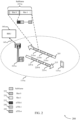
- FIG. 2 illustrates an example of a wireless communication system 200 that supports feedback processing techniques in wireless transmissions in accordance with various aspects of the present disclosure.
- Wireless communications system 200 includes base station 105-a and UE 115-a, which may be examples of aspects of the corresponding devices as described above with reference to FIG. 1 .
- the wireless communications system 200 may operate according to a radio access technology (RAT) such as a LTE, 5G, or NR RAT, although techniques described herein may be applied to any RAT and to systems that may concurrently use two or more different RATs.
- RAT radio access technology
- the wireless communication system 200 may be part of a C-RAN deployment, and a RRU 140-a may provide transmissions to a BBU at the base station 105-a for transmission to the UE 115-a.
- Base station 105-a may communicate with UE 115-a over an uplink carrier 205 and a downlink carrier 215. In some examples, base station 105-a may allocate resources for communication with UEs over uplink carrier 205 and downlink carrier 215. In C-RAN deployments, the RRU 140-a may allocate resources, and the BBU may transmit wireless transmissions according to the received transmissions from the RRU 140-a. For example, base station 105-a or RRU 140-a may allocate uplink subframes 210 in uplink carrier 205 for uplink transmissions from UE 115-a, and one or more uplink subframes 210 may correspond to a legacy LTE TTI of 1 ms.
- uplink subframes 210 may include a first uplink subframe 210-a, a second uplink subframe 210-b, and a third uplink subframe 210-c.
- Each of the uplink subframes 210 may include two slots, in which each slot may have seven OFDM symbols for a normal cyclic prefix.
- a first slot (slot 0) 225 and a second slot (slot 1) 230 may be included in the first subframe 210-a.
- Shortened TTIs may be included or coincide with a slot; sTTIs may include several sTTIs, like sTTI-0 235, sTTI-1, 240... , sTTI- n 245.
- TTI lengths may be used for transmissions over uplink carrier 205 and/or downlink carrier 215.
- two-symbol sTTI and 1-slot sTTI durations may be supported for physical uplink control channel (PUCCH) and physical uplink shared channel (PUSCH) transmissions (or shortened PUCCH (sPUCCH) and shortened PUSCH (sPUSCH) transmissions).
- UE 115-a may be semi-statically configured (e . g ., and/or dynamically triggered) with HRLLC while still maintaining legacy 1-ms TTI based communications.
- the possible combinations of 1-ms based TTI for a UE 115 may include 1-ms TTI with N+4 timing or N+3 timing.
- slot TTI or 2-symbol TTI lengths may be used with N+4 or N+6 timing.
- Such timing may be referred to as a processing timeline and may relate to the number of TTIs or sTTIs between a downlink transmission (e . g ., PDCCH, PUSCH, etc.) and a responsive uplink transmission ( e . g ., PUCCH, PUSCH, etc ., containing a HARQ feedback transmission).
- the timing may relate to an uplink transmission and a responsive downlink transmission (e . g ., PDSCH, retransmission, etc.).
- a processing timeline of n +4 with the maximum TA value of 667 ⁇ s may be assumed.
- the UE 115-a when receiving a transmission in a downlink TTI the UE 115-a, in a worst-case scenario, may have 3 ms minus the maximum TA for processing of the downlink transmission and preparing the responsive HARQ feedback transmission ( i . e ., 3 ms - 667 ⁇ s).
- this processing time may be reduced based on the shorter processing timelines that may be present in low latency communications.
- a maximum TA value may also be reduced, in order to provide the UE 115-a with sufficient processing time to receive a transmission, perform HARQ processing, and prepare the HARQ feedback transmission. Reducing the value of the maximum TA results in a corresponding reduction in the coverage area 110-a, as the UE 115-a may need to be closer to the base station 105-a.
- the maximum TA may be substantially reduced, which may limit the deployment scenarios where these features can be implemented.
- the propagation time between a RRU and BBU may be relatively large and processing timeline relative to when a RRU transmits a TTI may have a relatively large portion consumed be the TA associated with the RRC to BBU transmission.
- Various aspects of the present disclosure provide techniques that may allow a larger maximum TA to be used through configuring additional HARQ processes, as will be discussed in more detail below.
- FIG. 3 illustrates an example of uplink and downlink TTIs 300 in accordance with various aspects of the present disclosure.
- Uplink and downlink TTIs 300 may be used for communications between a UE 115 and a base station 105 such as discussed above with reference to FIGs. 1 and 2 .
- downlink TTIs 305 may be used for downlink transmissions from a base station 105 to a UE 115.
- uplink TTIs 310 may be used for uplink transmissions from a UE 115 to a base station 105.
- Uplink and downlink TTIs 300 illustrate aspects of n+4 timing and n+6 timing, as described above. As illustrated, uplink and downlink TTIs 300 each contain two slots.
- a first downlink TTI 320 may be transmitted to a UE 115, and the UE 115 may attempt to demodulate and decode the transmission and generate an ACK/NACK indication 325 that may be transmitted in uplink TTI 330, which may be a first uplink TTI that starts at or after n + 4 TTIs after the first downlink TTI 320.
- the base station may format a rescheduling and retransmission 335 to the UE, which may be transmitted in a first downlink TTI that starts at or after n+4 TTIs after the ACK/NACK indication 325, which in this example is downlink TTI-8 355.
- a round trip time in such a case is 8 TTIs.
- ACK/NACK feedback for downlink TTI-1 may be transmitted in uplink TTI-5
- ACK/NACK feedback for downlink TTI-2 may be transmitted in uplink TTI-6, and so on.
- a first downlink TTI 320 may be transmitted to a UE 115, and the UE 115 may attempt to demodulate and decode the transmission and generate an ACK/NACK indication 340 that may be transmitted in uplink TTI-6 345, which may be a first uplink TTI that starts at or after n + 6 TTIs after the first downlink TTI 320.
- the base station may format a rescheduling and retransmission 350 to the UE, which may be transmitted in a first downlink TTI that starts at or after n+6 TTIs after the ACK/NACK indication 340, which in this example is downlink TTI-12 360, thereby providing a RTT of 12 TTIs.
- additional HARQ processes may be dynamically configured at UE 115-a such that the HARQ processing may be performed.
- a processing timeline also may be adjusted based on UE capability.
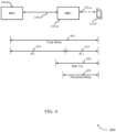
- FIG. 4 illustrates an example of a system 400 with a RRU and BBU, and related propagation delays, in accordance with various aspects of the present disclosure.
- system 400 may implement aspects of wireless communication system 100.
- System 400 may be an example of a portion of a C-RAN deployment, for example.
- a RRU 140-b may be connected with a BBU 105-b (which may be an example of a base station 105) or a network BBU device via, for example, a fiber connection 145-b.
- the BBU 105-b may transmit and receive wireless transmissions to and from UE 115-b via communications link 125-a.
- RRU 140-b may be connected to multiple BBUs, and each BBU may serve multiple UEs 115 in its coverage area.
- a total delay 405 may include a first delay 410 associated with the fiber connection 145-b and a second delay 415 associated with the communications link 125-a.
- an effective maximum TA in such a deployment is ⁇ T 1 + ⁇ T 2, or a combined maximum that includes propagation delays of both the connection 145-b and the communications link 125-a.
- a maximum TA 420 may be specified based on a service type, for example.
- the length of the fiber connection 145-b may be relatively long and result in a ⁇ T 1 that may be relatively large, e.g ., up to 200 ⁇ s ( e . g ., in deployments that have tens of kilometers between the BBU 105-b and RRU 140-b).
- ⁇ T 2 could be tens of ⁇ s.
- the net effect is that the overall TA from the total delay 405 could be large, which may imposes some burden on UE 115-b processing.
- a first number of HARQ processes may be configured, and if the second delay 415 is at or above the threshold delay 425, a second number of HARQ processes may be configured that is larger than the first number of HARQ processes.
- the number of HARQ processes is greater or equal to 2 ⁇ k , where k may be defined as discussed above (e.g., 16 HARQ processes for n+4 and n+6, and in such cases the number of HARQ processes may be fixed and not configurable).
- the UE 115-b may be configured a processing timeline with n + k when k may be defined as discussed above, for each service type, and the maximum TA may be defined only based on ⁇ T 2 415.
- a small TA value such as 67us can be chosen in all cases, and a HARQ processing timeline may be n + 4 or n + 6 for a 2-symbol TTI operation.
- HARQ processes For slot and 1ms TTIs, only one additional HARQ processes may needed. For example, when the processing timing is based on n + 4, instead of 8 HARQ processes, 10 HARQ processes may be configured for a 2-symbol operation, and 9 HARQ processes may be configured for the other two cases. In order to accommodate the additional HARQ processes, a 4-bit HARQ ID may be used to identify the HARQ processes. Furthermore, in some cases, additional HARQ processes, up to 16 HARQ processes, may be configured. Thus, instead of forcing UE 115-b to transmit earlier based on a larger TA, a UE 115-b may its UL later based on a smaller TA, but the difference is filled with additional HARQ processes. In some cases, the number of HARQ processes to consider is dependent on the value of ⁇ T 1 .
- a number of HARQ processes can be configurable, and under the n + 4 processing timing, it could may be either 8 or a new number of HARQ processes (e.g., 10 or up to 16).
- Such a configuration may be indicated to the UE 115-b either via a higher layer signaling ( e . g ., RRC signaling) or based on the DCI format signaled in DCI.
- the number of soft buffers may be defined based on the HARQ timing (e.g. 8 if n + 4 is adopted) or determined based on the UE capability ( e . g ., either 8 or the configured higher number of HARQ processes).
- the RTT could still be defined based on 2*k ( i . e ., the k in n+k).
- the UE 115-b may expect retransmissions starting at the eighth TTI even though 16 HARQs may be configured.
- a 2-symbol TTI the UE 115-b may expect re-transmission at the 10th TTI, but it may happen that some processing can be done faster and the RTT may remain 8 TTIs.
- the BBU 105-b may have all the modulated information and can re-transmit new packets with different redundancy versions (RVs), in which case the RTT may be 2*k as well.
- RVs redundancy versions
- the HARQ timing and TA are defined based on ⁇ T 2 , it is necessary to send the TTIs at the right location from BBU 105-b. For example, each 2-symbol sTTI should be sent at the defined TTI starting points in order to properly align with TTI boundaries.
- the RRU 140-b may estimate ⁇ T 1 and make sure that each packet arrives at BBU 105-b at the TTI boundary.
- the BBU 105-b may self-adjust such that each packet is transmitted to the UE 115-b at the TTI boundary.
- FIG. 5 illustrates an example of a process flow 500 that supports feedback processing techniques in wireless transmissions in accordance with various aspects of the present disclosure.
- process flow 500 may implement aspects of wireless communication system 100.
- Process flow 500 may include a base station 105-c and a UE 115-c, which may be examples of a base station and UE as discussed above.
- base station 105-c may establish a connection with UE 115-c.
- the connection established at 505 may be an example of a communication link 125 as described with reference to FIG. 1 .
- the wireless communications system within which UE 115-c and base station 105-c establish the connection at 505 may support a first wireless service having a TTI duration that is a 2-symbol or slot TTI.
- the first wireless service may be for HRLLC.
- the first wireless service may additionally or alternatively have a first target latency value and a second wireless service may have a second target latency value that is higher than the first target latency value.
- base station 105-c may identify a processing timeline and TTI duration for communications with UE 115-c.
- the processing timeline may be determined based on a TTI duration of the wireless service, and in some examples may also be based on capabilities of the UE 115-c.
- UE 115-c may transmit an indication of its processing capabilities as part of the connection establishment procedure 505, and lower capability UEs may be configured with a larger processing timeline ( e . g ., an n+6 timeline versus an n+4 timeline).
- the base station 105-c may identify TA values associated with transmissions to the UE 115-c.
- the TA values may be identified, for example, based on a reported TA value from the UE 115-c.
- the TA value may be based on two TA values, a first TA value associated with a transmission from a RRU to a BBC, and a second TA value based on propagation delay between the UE 115-c and base station 105-c.
- the TA values may be simply based on a TA value associated with the UE 115-c and base station 105-c, which may be a relatively large TA based on a location of the UE 115-c in coverage area of the base station 105-c.
- the base station 105-c may configure a number of HARQ processes at the UE 115-c. In some case, the base station 105-c may configure the number of HARQ processes based at least in part on the processing timeline, the TA, a TTI duration, or any combination thereof. Additionally or alternatively, the processing capability of the UE 115-c may also be considered in determining the number of HARQ processes to configure.
- the TA of the UE 115-c may be compared to a threshold propagation delay value, and if the TA is less than the threshold value, a first number of HARQ processes may be configured, and if the TA exceeds the threshold value one or more additional HARQ processes may be configured to allow the UE 115-c additional processing time.
- the base station 105-c may transmit configuration information 525 to the UE 115-c.
- a number of HARQ processes may be configured (e . g ., 16 HARQ processes) that is greater than a number of HARQ that would be needed for a particular HARQ timeline ( e . g ., greater than 2k HARQ processes for an n+k timeline).
- the UE 115-c may receive the configuration information 525 and, at block 530, configure HARQ processes.
- the number of HARQ processes configured at the UE 115-c may be based on information in the configuration information, which may be transmitted using RRC signaling or may be indicated in DCI, for example.
- the base station 105-c may transmit downlink transmission 535, which may be received at the UE 115-c.
- the UE 115-c, as part of receiving the downlink transmission 535, may perform HARQ processing at block 540, according to the HARQ configuration.
- the UE 115-c may transmit HARQ feedback message 545 to the base station 105-e, which may include ACK/NACK information for one or more received TTIs.
- the base station 105-c may determine, at block 550, whether a retransmission of the downlink transmission is needed, and if so may transmit downlink retransmission 555 to the UE 115-c.
- the RTT for the downlink retransmission 555 may be based on the configured processing timeline irrespective of a number of HARQ processes configured at the UE 115-c.
- FIG. 6 illustrates an example of a process flow 600 that supports feedback processing techniques in wireless transmissions in accordance with various aspects of the present disclosure.
- process flow 600 may implement aspects of wireless communication system 100.
- Process flow 600 may include a base station 105-d, which in this example, may be a BBU, a UE 115-d, and a RRU 140-c, which may be examples of a BBU, RRU, and UE as discussed above.
- RRU 140-c via BBU 105-d, may establish a connection with UE 115-d.
- the connection established at 605 may be an example of a communication link 125 as described with reference to FIG. 1 .
- the wireless communications system within which UE 115-d and BBU 105-d establish the connection at 605 may support a first wireless service having a TTI duration that is a 2-symbol or slot TTI.
- the first wireless service may be for HRLLC.
- the first wireless service may additionally or alternatively have a first target latency value and a second wireless service may have a second target latency value that is higher than the first target latency value.
- a maximum TA value at the UE 115-d may be based only on a TA between the UE 115-d and the BBU 105-d.
- timing adjustments for the connection between the BBU 105-d and the RRU 140-c may need to be accounted for. As discussed above, such adjustments may be made at either the RRU 140-c or the BBU 105-d.
- the RRU 140-c may estimate a RRU-BBU delay.
- the RRU-BBU delay may be a fixed delay based on a length of a fiber connection that connects the RRU and BBU. In some cases, the delay may be measured at one or both of the RRU 140-c or BBU 105-d, or may be configured.
- the RRU 140-c may adjust transmission times for transmissions such that they arrive at the BBU 105-d aligned with TTIs.
- the RRU 140-c may transmit downlink transmission 620-a to the BBU 105-d, which may in turn transmit downlink transmission 625-a to the UE 115-d.
- the BBU 105-d may estimate a RRU-BBU delay.
- the RRU-BBU delay may be a fixed delay based on a length of a fiber connection that connects the RRU and BBU. In some cases, the delay may be measured at one or both of the RRU 140-c or BBU 105-d, or may be configured.
- the BBU 105-d may receive downlink transmission 620-b from the RRU 140-c and, at block 635, the BBU 105-d may delay the transmission to be aligned with a TTI boundary. The BBU 105-d may then transmit downlink transmission 625-b to the UE 115-d.
- FIG. 7 shows a block diagram 700 of a wireless device 705 that supports feedback processing techniques in wireless transmissions in accordance with aspects of the present disclosure.
- Wireless device 705 may be an example of aspects of a base station 105 as described with reference to FIG. 1 .
- Wireless device 705 may include receiver 710, base station hybrid automatic repeat request (HARQ) manager 715, and transmitter 720.
- HARQ base station hybrid automatic repeat request
- Wireless device 705 may also include a processor. Each of these components may be in communication with one another (e.g., via one or more buses).
- Receiver 710 may receive information such as packets, user data, or control information associated with various information channels (e . g ., control channels, data channels, and information related to feedback processing techniques in wireless transmissions, etc.). Information may be passed on to other components of the device.
- the receiver 710 may be an example of aspects of the transceiver 1035 described with reference to FIG. 10 .
- the receiver 710 may utilize a single antenna or a set of antennas.
- Base station HARQ manager 715 may be an example of aspects of the base station HARQ manager 1015 described with reference to FIG. 10 .
- Base station HARQ manager 715 and/or at least some of its various sub-components may be implemented in hardware, software executed by a processor, firmware, or any combination thereof. If implemented in software executed by a processor, the functions of the base station HARQ manager 715 and/or at least some of its various sub-components may be executed by a general-purpose processor, a digital signal processor (DSP), an application-specific integrated circuit (ASIC), an field-programmable gate array (FPGA) or other programmable logic device, discrete gate or transistor logic, discrete hardware components, or any combination thereof designed to perform the functions described in the present disclosure.
- DSP digital signal processor
- ASIC application-specific integrated circuit
- FPGA field-programmable gate array
- the base station HARQ manager 715 and/or at least some of its various sub-components may be physically located at various positions, including being distributed such that portions of functions are implemented at different physical locations by one or more physical devices.
- base station HARQ manager 715 and/or at least some of its various sub-components may be a separate and distinct component in accordance with various aspects of the present disclosure.
- base station HARQ manager 715 and/or at least some of its various sub-components may be combined with one or more other hardware components, including but not limited to an I/O component, a transceiver, a network server, another computing device, one or more other components described in the present disclosure, or a combination thereof in accordance with various aspects of the present disclosure.
- Base station HARQ manager 715 identifies a processing timeline for a user equipment (UE) to transmit a HARQ feedback transmission in response to a downlink transmission, the processing timeline including a duration of time between the downlink transmission and an uplink transmission that includes the HARQ feedback, determines a configuration establishing a number of HARQ processes for use by the UE, the number of HARQ processes based on the processing timeline, a TA of the UE, and a duration of transmission time interval (TTI)s associated with the HARQ feedback transmission, and transmits the configuration to the UE.
- TTI transmission time interval
- Transmitter 720 may transmit signals generated by other components of the device.
- the transmitter 720 may be collocated with a receiver 710 in a transceiver module.
- the transmitter 720 may be an example of aspects of the transceiver 1035 described with reference to FIG. 10 .
- the transmitter 720 may utilize a single antenna or a set of antennas.
- FIG. 8 shows a block diagram 800 of a wireless device 805 that supports feedback processing techniques in wireless transmissions in accordance with aspects of the present disclosure.
- Wireless device 805 may be an example of aspects of a wireless device 705 or a base station 105 as described with reference to FIG. 7 .
- Wireless device 805 may include receiver 810, base station HARQ manager 815, and transmitter 820.
- Wireless device 805 may also include a processor. Each of these components may be in communication with one another (e.g., via one or more buses).
- Receiver 810 may receive information such as packets, user data, or control information associated with various information channels (e . g ., control channels, data channels, and information related to feedback processing techniques in wireless transmissions, etc.). Information may be passed on to other components of the device.
- the receiver 810 may be an example of aspects of the transceiver 1035 described with reference to FIG. 10 .
- the receiver 810 may utilize a single antenna or a set of antennas.
- Base station HARQ manager 815 may be an example of aspects of the base station HARQ manager 1015 described with reference to FIG. 10 .
- Base station HARQ manager 815 may also include processing timeline component 825, configuration manager 830, and transmission manager 835.
- Processing timeline component 825 identifies a processing timeline for a UE to transmit a HARQ feedback transmission in response to a downlink transmission, the processing timeline including a duration of time between the downlink transmission and an uplink transmission that includes the HARQ feedback.
- Configuration manager 830 determines a configuration establishing a number of HARQ processes for use by the UE, the number of HARQ processes based on the processing timeline, a TA of the UE, a duration of TTIs associated with the HARQ feedback transmission, or any combination thereof.
- the determining the configuration further includes identifying a threshold TA value for setting the number of HARQ processes at the UE, comparing the TA of the UE to the threshold propagation delay value, and setting a first number of HARQ processes or a second number of HARQ processes for use by the UE based on whether the TA of the UE is less than or greater than the threshold propagation delay value, where the first number of HARQ processes is less than the second number of HARQ processes.
- the threshold propagation delay value corresponds to a value of a propagation delay at which the UE is capable of performing HARQ processing using the first number of HARQ processes.
- a maximum TA value is determined for the UE based on a coverage area of a base station serving the UE.
- the determining the configuration further includes identifying the TA of the UE based on a first TA value for transmissions between the UE and a BBU and a second TA value for transmissions between the BBU and a RRU, and where the number of HARQ processes is based on the second TA value.
- the determining the configuration further includes comparing the second TA value to a threshold TA value, and where the number of HARQ processes is further determined based on the comparing.
- the first TA value is based on a wireless propagation delay between the UE and the BBU and the second TA value is based on a fiber connection propagation delay between the BBU and the RRU.
- the identifying the processing timeline further includes determining a maximum TA value for the UE, and determining the processing timeline based on the maximum TA value. In some cases, the processing timeline is further based on a processing capability of the UE.
- Transmission manager 835 transmits the configuration to the UE.
- the transmitting the configuration to the UE includes transmitting radio resource control (RRC) signaling to the UE or downlink control information (DCI) to the UE that includes configuration information.
- RRC radio resource control
- DCI downlink control information
- Transmitter 820 may transmit signals generated by other components of the device.
- the transmitter 820 may be collocated with a receiver 810 in a transceiver module.
- the transmitter 820 may be an example of aspects of the transceiver 1035 described with reference to FIG. 10 .
- the transmitter 820 may utilize a single antenna or a set of antennas.
- FIG. 9 shows a block diagram 900 of a base station HARQ manager 915 that supports feedback processing techniques in wireless transmissions in accordance with aspects of the present disclosure.
- the base station HARQ manager 915 may be an example of aspects of a base station HARQ manager 715, a base station HARQ manager 815, or a base station HARQ manager 1015 described with reference to FIGs. 7 , 8 , and 10 .
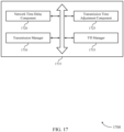
- the base station HARQ manager 915 may include processing timeline component 920, configuration manager 925, transmission manager 930, processing capability component 935, TTI manager 940, HARQ ID manager 945, and RTT manager 950. Each of these modules may communicate, directly or indirectly, with one another ( e . g ., via one or more buses).
- Processing timeline component 920 identifies a processing timeline for a UE to transmit a HARQ feedback transmission in response to a downlink transmission, the processing timeline including a duration of time between the downlink transmission and an uplink transmission that includes the HARQ feedback.
- Configuration manager 925 determines a configuration establishing a number of HARQ processes for use by the UE, the number of HARQ processes based on the processing timeline, a TA of the UE, and a duration of TTIs associated with the HARQ feedback transmission.
- the determining the configuration further includes identifying a threshold TA value for setting the number of HARQ processes at the UE, comparing the TA of the UE to the threshold propagation delay value, and setting a first number of HARQ processes or a second number of HARQ processes for use by the UE based on whether the TA of the UE is less than or greater than the threshold propagation delay value, where the first number of HARQ processes is less than the second number of HARQ processes.
- the threshold propagation delay value corresponds to a value of a propagation delay at which the UE is capable of performing HARQ processing using the first number of HARQ processes.
- a maximum TA value is determined for the UE based on a coverage area of a base station serving the UE.
- the determining the configuration further includes identifying the TA of the UE based on a first TA value for transmissions between the UE and a BBU and a second TA value for transmissions between the BBU and a RRU, and where the number of HARQ processes is based on the second TA value.
- the determining the configuration further includes comparing the second TA value to a threshold TA value, and where the number of HARQ processes is further determined based on the comparing.
- the first TA value is based on a wireless propagation delay between the UE and the BBU and the second TA value is based on a fiber connection propagation delay between the BBU and the RRU.
- the identifying the processing timeline further includes determining a maximum TA value for the UE, and determining the processing timeline based on the maximum TA value. In some cases, the processing timeline is further based on a processing capability of the UE.
- Transmission manager 930 transmits the configuration to the UE.
- the transmitting the configuration to the UE includes transmitting RRC signaling to the UE or DCI to the UE that includes configuration information.
- Processing capability component 935 may configure UEs having a greater processing capability with fewer HARQ processes than UEs having lower processing capability.
- the determining the configuration further includes identifying a processing capability of the UE, and determining the number of HARQ processes based on the processing capability of the UE and the TA of the UE.
- the UE reports a UE capability, such as UE class.
- TTI manager 940 may manage TTIs based on a TTI duration.
- a first TTI of the first transmission corresponds to a 2-symbol TTI or a slot TTI, and where the processing timeline is based on the TTI duration of the first transmission
- a second TTI of a second transmission corresponds to a 1-ms TTI and has a different processing timeline, such as a N+3 processing timeline or an N+4 processing timeline.
- HARQ ID manager 945 may assign a HARQ ID to different HARQ processes for different TTIs. In some cases, the HARQ feedback transmission is associated with a four-bit HARQ ID.
- RTT manager 950 may configure a RTT for the HARQ feedback transmission and an associated retransmission of the downlink transmission, the RTT based on the processing timeline irrespective of the number of HARQ processes.
- the RTT is set based on a TTI duration of the TTI and the number of HARQ processes is based on the processing timeline, the TTI duration, and the TA between the BBU and the RRU.
- FIG. 10 shows a diagram of a system 1000 including a device 1005 that supports feedback processing techniques in wireless transmissions in accordance with aspects of the present disclosure.
- Device 1005 may be an example of or include the components of wireless device 705, wireless device 805, or a base station 105 as described above, e . g ., with reference to FIGs. 7 and 8 .
- Device 1005 may include components for bi-directional voice and data communications including components for transmitting and receiving communications, including base station HARQ manager 1015, processor 1020, memory 1025, software 1030, transceiver 1035, antenna 1040, network communications manager 1045, and inter-station communications manager 1050. These components may be in electronic communication via one or more busses ( e . g ., bus 1010).
- Device 1005 may communicate wirelessly with one or more UEs 115.
- Processor 1020 may include an intelligent hardware device, (e . g ., a general-purpose processor, a DSP, a central processing unit (CPU), a microcontroller, an ASIC, an FPGA, a programmable logic device, a discrete gate or transistor logic component, a discrete hardware component, or any combination thereof).
- processor 1020 may be configured to operate a memory array using a memory controller.
- a memory controller may be integrated into processor 1020.
- Processor 1020 may be configured to execute computer-readable instructions stored in a memory to perform various functions (e . g ., functions or tasks supporting feedback processing techniques in wireless transmissions).
- Memory 1025 may include random access memory (RAM) and read only memory (ROM).
- the memory 1025 may store computer-readable, computer-executable software 1030 including instructions that, when executed, cause the processor to perform various functions described herein.
- the memory 1025 may contain, among other things, a basic input/output system (BIOS) which may control basic hardware and/or software operation such as the interaction with peripheral components or devices.
- BIOS basic input/output system
- Software 1030 may include code to implement aspects of the present disclosure, including code to support feedback processing techniques in wireless transmissions.
- Software 1030 may be stored in a non-transitory computer-readable medium such as system memory or other memory. In some cases, the software 1030 may not be directly executable by the processor but may cause a computer ( e . g ., when compiled and executed) to perform functions described herein.
- Transceiver 1035 may communicate bi-directionally, via one or more antennas, wired, or wireless links as described above.
- the transceiver 1035 may represent a wireless transceiver and may communicate bi-directionally with another wireless transceiver.
- the transceiver 1035 may also include a modem to modulate the packets and provide the modulated packets to the antennas for transmission, and to demodulate packets received from the antennas.
- the wireless device may include a single antenna 1040. However, in some cases the device may have more than one antenna 1040, which may be capable of concurrently transmitting or receiving multiple wireless transmissions.
- Network communications manager 1045 may manage communications with the core network ( e . g ., via one or more wired backhaul links). For example, the network communications manager 1045 may manage the transfer of data communications for client devices, such as one or more UEs 115.
- Inter-station communications manager 1050 may manage communications with other base station 105, and may include a controller or scheduler for controlling communications with UEs 115 in cooperation with other base stations 105. For example, the inter-station communications manager 1050 may coordinate scheduling for transmissions to UEs 115 for various interference mitigation techniques such as beamforming or joint transmission. In some examples, inter-station communications manager 1050 may provide an X2 interface within an Long Term Evolution (LTE)/LTE-A wireless communication network technology to provide communication between base stations 105.
- LTE Long Term Evolution
- LTE-A wireless communication network technology to provide communication between base stations 105.
- FIG. 11 shows a block diagram 1100 of a wireless device 1105 that supports feedback processing techniques in wireless transmissions in accordance with aspects of the present disclosure.
- Wireless device 1105 may be an example of aspects of a UE 115 as described with reference to FIG. 1 .
- Wireless device 1105 may include receiver 1110, UE HARQ manager 1115, and transmitter 1120.
- Wireless device 1105 may also include a processor. Each of these components may be in communication with one another ( e . g ., via one or more buses).
- Receiver 1110 may receive information such as packets, user data, or control information associated with various information channels (e . g ., control channels, data channels, and information related to feedback processing techniques in wireless transmissions, etc.). Information may be passed on to other components of the device.
- the receiver 1110 may be an example of aspects of the transceiver 1435 described with reference to FIG. 14 .
- the receiver 1110 may utilize a single antenna or a set of antennas.
- Receiver 1110 may receive the downlink transmission from the base station. In some cases, receiver may receive configuration information via RRC signaling or DCI.
- UE HARQ manager 1115 may be an example of aspects of the UE HARQ manager 1415 described with reference to FIG. 14 .
- UE HARQ manager 1115 and/or at least some of its various sub-components may be implemented in hardware, software executed by a processor, firmware, or any combination thereof. If implemented in software executed by a processor, the functions of the UE HARQ manager 1115 and/or at least some of its various sub-components may be executed by a general-purpose processor, a DSP, an ASIC, an FPGA or other programmable logic device, discrete gate or transistor logic, discrete hardware components, or any combination thereof designed to perform the functions described in the present disclosure.
- the UE HARQ manager 1115 and/or at least some of its various sub-components may be physically located at various positions, including being distributed such that portions of functions are implemented at different physical locations by one or more physical devices.
- UE HARQ manager 1115 and/or at least some of its various sub-components may be a separate and distinct component in accordance with various aspects of the present disclosure. In other examples, UE HARQ manager 1115 and/or at least some of its various sub-components may be combined with one or more other hardware components, including but not limited to an I/O component, a transceiver, a network server, another computing device, one or more other components described in the present disclosure, or a combination thereof in accordance with various aspects of the present disclosure.
- UE HARQ manager 1115 identifies a TA for transmissions between the UE and a base station, transmit an indication of the TA to the base station, and receives configuration information from the base station that indicates a number of HARQ processes that are to be configured at the UE based on the TA and a duration of TTIs associated with the HARQ processes.
- Transmitter 1120 may transmit signals generated by other components of the device.
- the transmitter 1120 may be collocated with a receiver 1110 in a transceiver module.
- the transmitter 1120 may be an example of aspects of the transceiver 1435 described with reference to FIG. 14 .
- the transmitter 1120 may utilize a single antenna or a set of antennas.
- FIG. 12 shows a block diagram 1200 of a wireless device 1205 that supports feedback processing techniques in wireless transmissions in accordance with aspects of the present disclosure.
- Wireless device 1205 may be an example of aspects of a wireless device 1105 or a UE 115 as described with reference to FIG. 11 .
- Wireless device 1205 may include receiver 1210, UE HARQ manager 1215, and transmitter 1220.
- Wireless device 1205 may also include a processor. Each of these components may be in communication with one another (e.g., via one or more buses).
- Receiver 1210 may receive information such as packets, user data, or control information associated with various information channels (e.g., control channels, data channels, and information related to feedback processing techniques in wireless transmissions, etc.). Information may be passed on to other components of the device.
- the receiver 1210 may be an example of aspects of the transceiver 1435 described with reference to FIG. 14 .
- the receiver 1210 may utilize a single antenna or a set of antennas.
- UE HARQ manager 1215 may be an example of aspects of the UE HARQ manager 1415 described with reference to FIG. 14 .
- UE HARQ manager 1215 may also include TA manager 1225 and configuration manager 1230.
- TA manager 1225 identifies at a UE, a TA for transmissions between the UE and a base station and transmits an indication of the TA to the base station.
- Configuration manager 1230 receives configuration information from the base station that indicates a number of HARQ processes that are to be configured at the UE based on the TA and a duration of TTIs associated with the HARQ processes.
- the configuration information includes a threshold TA value for setting the number of HARQ processes at the UE, and where the TA may be compared to the threshold propagation delay value, and a first number of HARQ processes or a second number of HARQ processes set based on whether the TA is less than or greater than the threshold propagation delay value, where the first number of HARQ processes is less than the second number of HARQ processes.
- Transmitter 1220 may transmit signals generated by other components of the device.
- the transmitter 1220 may be collocated with a receiver 1210 in a transceiver module.
- the transmitter 1220 may be an example of aspects of the transceiver 1435 described with reference to FIG. 14 .
- the transmitter 1220 may utilize a single antenna or a set of antennas.
- FIG. 13 shows a block diagram 1300 of a UE HARQ manager 1315 that supports feedback processing techniques in wireless transmissions in accordance with aspects of the present disclosure.
- the UE HARQ manager 1315 may be an example of aspects of a UE HARQ manager 1415 described with reference to FIGs. 11 , 12 , and 14 .
- the UE HARQ manager 1315 may include TA manager 1320, configuration manager 1325, processing timeline component 1330, decoding component 1335, acknowledgement (ACK)/negative acknowledgement (NACK) component 1340, processing capability component 1345, soft buffer manager 1350, and RTT manager 1355. Each of these modules may communicate, directly or indirectly, with one another ( e . g ., via one or more buses).
- TA manager 1320 identifies, at a UE, a TA for transmissions between the UE and a base station and transmits an indication of the TA to the base station.
- Configuration manager 1325 receives configuration information from the base station that indicates a number of HARQ processes that are to be configured at the UE based on the TA and a duration of TTIs associated with the HARQ processes.
- the configuration information includes a threshold TA value for setting the number of HARQ processes at the UE, and the TA may be compared to the threshold propagation delay value, and a first number of HARQ processes or a second number of HARQ processes set based on whether the TA is less than or greater than the threshold propagation delay value, where the first number of HARQ processes is less than the second number of HARQ processes.
- Processing timeline component 1330 receives a processing timeline in the configuration information, the processing timeline including a duration of time between a downlink transmission from the base station and an uplink transmission to the base station that includes HARQ feedback, the processing timeline based on the duration of the TTIs.
- the processing timeline is based on a maximum TA value for the UE.
- the processing timeline is further based on a processing capability of the UE.
- Decoding component 1335 may process the downlink transmission according to a first HARQ process to generate ACK/NACK feedback, the first HARQ process associated with a four-bit HARQ ID.
- ACK/NACK component 1340 may transmit the ACK/NACK feedback according to the processing timeline.
- Processing capability component 1345 may transmit an indication of a processing capability of the UE to the base station, and where the number of HARQ processes is further based on the processing capability.
- Soft buffer manager 1350 may configure a set of soft buffers for buffering received transmissions associated with one or more of the HARQ processes, a number of the soft buffers based on a number of TTIs in a processing timeline or the number of HARQ processes.
- RTT manager 1355 may manage RTTs for different transmissions.
- the configuration information further includes an indication of a RTT for HARQ feedback transmissions and associated retransmissions, the RTT based on a processing timeline for HARQ feedback and irrespective of the number of HARQ processes.
- FIG. 14 shows a diagram of a system 1400 including a device 1405 that supports feedback processing techniques in wireless transmissions in accordance with aspects of the present disclosure.
- Device 1405 may be an example of or include the components of UE 115 as described above, e . g ., with reference to FIG. 1 .
- Device 1405 may include components for bi-directional voice and data communications including components for transmitting and receiving communications, including UE HARQ manager 1415, processor 1420, memory 1425, software 1430, transceiver 1435, antenna 1440, and I/O controller 1445. These components may be in electronic communication via one or more busses ( e . g ., bus 1410).
- Device 1405 may communicate wirelessly with one or more base stations 105.
- Processor 1420 may include an intelligent hardware device, (e . g ., a general-purpose processor, a DSP, a CPU, a microcontroller, an ASIC, an FPGA, a programmable logic device, a discrete gate or transistor logic component, a discrete hardware component, or any combination thereof).
- processor 1420 may be configured to operate a memory array using a memory controller.
- a memory controller may be integrated into processor 1420.
- Processor 1420 may be configured to execute computer-readable instructions stored in a memory to perform various functions (e.g., functions or tasks supporting feedback processing techniques in wireless transmissions).
- Memory 1425 may include RAM and ROM.
- the memory 1425 may store computer-readable, computer-executable software 1430 including instructions that, when executed, cause the processor to perform various functions described herein.
- the memory 1425 may contain, among other things, a BIOS which may control basic hardware and/or software operation such as the interaction with peripheral components or devices.
- Software 1430 may include code to implement aspects of the present disclosure, including code to support feedback processing techniques in wireless transmissions.
- Software 1430 may be stored in a non-transitory computer-readable medium such as system memory or other memory. In some cases, the software 1430 may not be directly executable by the processor but may cause a computer ( e . g ., when compiled and executed) to perform functions described herein.
- Transceiver 1435 may communicate bi-directionally, via one or more antennas, wired, or wireless links as described above.
- the transceiver 1435 may represent a wireless transceiver and may communicate bi-directionally with another wireless transceiver.
- the transceiver 1435 may also include a modem to modulate the packets and provide the modulated packets to the antennas for transmission, and to demodulate packets received from the antennas.
- the wireless device may include a single antenna 1440. However, in some cases the device may have more than one antenna 1440, which may be capable of concurrently transmitting or receiving multiple wireless transmissions.
- I/O controller 1445 may manage input and output signals for device 1405. I/O controller 1445 may also manage peripherals not integrated into device 1405. In some cases, I/O controller 1445 may represent a physical connection or port to an external peripheral. In some cases, I/O controller 1445 may utilize an operating system such as iOS ® , ANDROID ® , MS-DOS ® , MS-WINDOWS ® , OS/2 ® , UNIX ® , LINUX ® , or another known operating system. In other cases, I/O controller 1445 may represent or interact with a modem, a keyboard, a mouse, a touchscreen, or a similar device. In some cases, I/O controller 1445 may be implemented as part of a processor. In some cases, a user may interact with device 1405 via I/O controller 1445 or via hardware components controlled by I/O controller 1445.
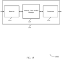
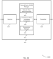
- FIG. 15 shows a block diagram 1500 of a wireless device 1505 that supports feedback processing techniques in wireless transmissions in accordance with aspects of the present disclosure.
- Wireless device 1505 may be an example of aspects of a network entity RRU 140 or BBU as described with reference to FIG. 1 .
- Wireless device 1505 may include receiver 1510, network entity HARQ manager 1515, and transmitter 1520.
- Wireless device 1505 may also include a processor. Each of these components may be in communication with one another ( e . g ., via one or more buses).
- Receiver 1510 may receive information such as packets, user data, or control information associated with various information channels (e . g ., control channels, data channels, and information related to feedback processing techniques in wireless transmissions, etc.). Information may be passed on to other components of the device.
- the receiver 1510 may be an example of aspects of the transceiver 1835 described with reference to FIG. 18 .
- the receiver 1510 may utilize a single antenna or a set of antennas.
- Network entity HARQ manager 1515 may be an example of aspects of the network entity HARQ manager 1815 described with reference to FIG. 18 .
- Network entity HARQ manager 1515 and/or at least some of its various sub-components may be implemented in hardware, software executed by a processor, firmware, or any combination thereof. If implemented in software executed by a processor, the functions of the network entity HARQ manager 1515 and/or at least some of its various sub-components may be executed by a general-purpose processor, a DSP, an ASIC, an FPGA or other programmable logic device, discrete gate or transistor logic, discrete hardware components, or any combination thereof designed to perform the functions described in the present disclosure. The network entity HARQ manager 1515 and/or at least some of its various sub-components may be physically located at various positions, including being distributed such that portions of functions are implemented at different physical locations by one or more physical devices.
- network entity HARQ manager 1515 and/or at least some of its various sub-components may be a separate and distinct component in accordance with various aspects of the present disclosure.
- network entity HARQ manager 1515 and/or at least some of its various sub-components may be combined with one or more other hardware components, including but not limited to an I/O component, a transceiver, a network server, another computing device, one or more other components described in the present disclosure, or a combination thereof in accordance with various aspects of the present disclosure.
- Network entity HARQ manager 1515 may identify, at a central network node, a time delay associated with a first transmission from the central network node to a BBU, where the first transmission is to be transmitted from the BBU to a UE over a wireless communications link, adjust a transmission time of the first transmission based on the time delay to provide that the first transmission arrives at the BBU for transmission to the UE at a start of a first TTI associated with the first transmission, and transmit the first transmission to the BBU according to the adjusted transmission time.
- the network entity HARQ manager 1515 may also receive, at a BBU, a first transmission from a central network node, where the first transmission is to be transmitted from the BBU to a UE over a wireless communications link, identify a time delay associated with the first transmission from the central network node, adjust a transmission time for transmitting the first transmission to the UE based on the time delay to align a start of the first transmission with a starting boundary of a first TTI associated with the first transmission, and transmit the first transmission to the UE according to the adjusted transmission time.
- Transmitter 1520 may transmit signals generated by other components of the device.
- the transmitter 1520 may be collocated with a receiver 1510 in a transceiver module.
- the transmitter 1520 may be an example of aspects of the transceiver 1835 described with reference to FIG. 18 .
- the transmitter 1520 may utilize a single antenna or a set of antennas.
- FIG. 16 shows a block diagram 1600 of a wireless device 1605 that supports feedback processing techniques in wireless transmissions in accordance with aspects of the present disclosure.
- Wireless device 1605 may be an example of aspects of a wireless device 1505 a network entity RRU 140, or a BBU as described with reference to FIG. 15 .
- Wireless device 1605 may include receiver 1610, network entity HARQ manager 1615, and transmitter 1620.
- Wireless device 1605 may also include a processor. Each of these components may be in communication with one another ( e . g ., via one or more buses).
- Receiver 1610 may receive information such as packets, user data, or control information associated with various information channels (e.g., control channels, data channels, and information related to feedback processing techniques in wireless transmissions, etc.). Information may be passed on to other components of the device.
- the receiver 1610 may be an example of aspects of the transceiver 1835 described with reference to FIG. 18 .
- the receiver 1610 may utilize a single antenna or a set of antennas.
- Network entity HARQ manager 1615 may be an example of aspects of the network entity HARQ manager 1815 described with reference to FIG. 18 .
- Network entity HARQ manager 1615 may also include network time delay component 1625, transmission time adjustment component 1630, and transmission manager 1635.
- Network time delay component 1625 may identify, at a central network node, a time delay associated with a first transmission from the central network node to a BBU, where the first transmission is to be transmitted from the BBU to a UE over a wireless communications link and identify a time delay associated with the first transmission from the central network node.
- the time delay is associated with a propagation delay of a fiber connection between the central network node and the BBU. In some cases, the time delay is associated with a propagation delay of a fiber connection between the central network node and the BBU.
- Transmission time adjustment component 1630 may adjust a transmission time of the first transmission based on the time delay to provide that the first transmission arrives at the BBU for transmission to the UE at a start of a first TTI associated with the first transmission and adjust a transmission time for transmitting the first transmission to the UE based on the time delay to align a start of the first transmission with a starting boundary of a first TTI associated with the first transmission.
- Transmission manager 1635 may transmit the first transmission to the BBU according to the adjusted transmission time, receive, at a BBU, a first transmission from a central network node, where the first transmission is to be transmitted from the BBU to a UE over a wireless communications link, and transmit the first transmission to the UE according to the adjusted transmission time.
- Transmitter 1620 may transmit signals generated by other components of the device.
- the transmitter 1620 may be collocated with a receiver 1610 in a transceiver module.
- the transmitter 1620 may be an example of aspects of the transceiver 1835 described with reference to FIG. 18 .
- the transmitter 1620 may utilize a single antenna or a set of antennas.
- FIG. 17 shows a block diagram 1700 of a network entity HARQ manager 1715 that supports feedback processing techniques in wireless transmissions in accordance with aspects of the present disclosure.
- the network entity HARQ manager 1715 may be an example of aspects of a network entity HARQ manager 1815 described with reference to FIGs. 15 , 16 , and 18 .
- the network entity HARQ manager 1715 may include network time delay component 1720, transmission time adjustment component 1725, transmission manager 1730, and TTI manager 1735. Each of these modules may communicate, directly or indirectly, with one another ( e . g ., via one or more buses).
- Network time delay component 1720 may identify, at a central network node, a time delay associated with a first transmission from the central network node to a BBU, where the first transmission is to be transmitted from the BBU to a UE over a wireless communications link and identify a time delay associated with the first transmission from the central network node.
- the time delay is associated with a propagation delay of a fiber connection between the central network node and the BBU. In some cases, the time delay is associated with a propagation delay of a fiber connection between the central network node and the BBU.
- Transmission time adjustment component 1725 may adjust a transmission time of the first transmission based on the time delay to provide that the first transmission arrives at the BBU for transmission to the UE at a start of a first TTI associated with the first transmission and adjust a transmission time for transmitting the first transmission to the UE based on the time delay to align a start of the first transmission with a starting boundary of a first TTI associated with the first transmission.
- Transmission manager 1730 may transmit the first transmission to the BBU according to the adjusted transmission time, receive, at a BBU, a first transmission from a central network node, where the first transmission is to be transmitted from the BBU to a UE over a wireless communications link, and transmit the first transmission to the UE according to the adjusted transmission time.
- TTI manager 1735 may identify a TTI duration for one or more wireless services.
- the first TTI of the first transmission is shorter than a second TTI of a second transmission from the central network node to the BBU.
- the first TTI is a 2-symbol or slot TTI
- the second TTI is a 1-ms TTI.
- the first TTI of the first transmission is shorter than a second TTI of a second transmission from the central network node to the BBU.
- the first TTI is a 2-symbol or slot TTI
- the second TTI is a 1-ms TTI.
- FIG. 18 shows a diagram of a system 1800 including a device 1805 that supports feedback processing techniques in wireless transmissions in accordance with aspects of the present disclosure.
- Device 1805 may be an example of or include the components of network entity RRU 140 or BBU as described above, e . g ., with reference to FIG. 1 .
- Device 1805 may include components for bi-directional voice and data communications including components for transmitting and receiving communications, including network entity HARQ manager 1815, processor 1820, memory 1825, software 1830, transceiver 1835, and I/O controller 1840. These components may be in electronic communication via one or more busses ( e . g ., bus 1810).
- busses e . g ., bus 1810
- Processor 1820 may include an intelligent hardware device, (e . g ., a general-purpose processor, a DSP, a CPU, a microcontroller, an ASIC, an FPGA, a programmable logic device, a discrete gate or transistor logic component, a discrete hardware component, or any combination thereof).
- processor 1820 may be configured to operate a memory array using a memory controller.
- a memory controller may be integrated into processor 1820.
- Processor 1820 may be configured to execute computer-readable instructions stored in a memory to perform various functions (e . g ., functions or tasks supporting feedback processing techniques in wireless transmissions).
- Memory 1825 may include RAM and ROM.
- the memory 1825 may store computer-readable, computer-executable software 1830 including instructions that, when executed, cause the processor to perform various functions described herein.
- the memory 1825 may contain, among other things, a BIOS which may control basic hardware and/or software operation such as the interaction with peripheral components or devices.
- Software 1830 may include code to implement aspects of the present disclosure, including code to support feedback processing techniques in wireless transmissions.
- Software 1830 may be stored in a non-transitory computer-readable medium such as system memory or other memory. In some cases, the software 1830 may not be directly executable by the processor but may cause a computer ( e . g ., when compiled and executed) to perform functions described herein.
- Transceiver 1835 may communicate bi-directionally, via one or more antennas, wired, or wireless links as described above.
- the transceiver 1835 may represent a wireless transceiver and may communicate bi-directionally with another wireless transceiver.
- the transceiver 1835 may also include a modem to modulate the packets and provide the modulated packets to the antennas for transmission, and to demodulate packets received from the antennas.
- I/O controller 1840 may manage input and output signals for device 1805. I/O controller 1840 may also manage peripherals not integrated into device 1805. In some cases, I/O controller 1840 may represent a physical connection or port to an external peripheral. In some cases, I/O controller 1840 may utilize an operating system such as iOS ® , ANDROID ® , MS-DOS ® , MS-WINDOWS ® , OS/2 ® , UNIX ® , LINUX ® , or another known operating system. In other cases, I/O controller 1840 may represent or interact with a modem, a keyboard, a mouse, a touchscreen, or a similar device. In some cases, I/O controller 1840 may be implemented as part of a processor. In some cases, a user may interact with device 1805 via I/O controller 1840 or via hardware components controlled by I/O controller 1840.
- FIG. 19 shows a flowchart illustrating a method 1900 for feedback processing techniques in wireless transmissions in accordance with aspects of the present disclosure.
- the operations of method 1900 may be implemented by a base station 105 or its components as described herein.
- the operations of method 1900 may be performed by a base station HARQ manager as described with reference to FIGs. 7 through 10 .
- a base station 105 may execute a set of codes to control the functional elements of the device to perform the functions described below. Additionally or alternatively, the base station 105 may perform aspects of the functions described below using special-purpose hardware.
- the base station 105 identifies, a processing timeline for a UE to transmit a HARQ feedback transmission in response to a downlink transmission, the processing timeline comprising a duration of time between the downlink transmission and an uplink transmission that includes the HARQ feedback.
- the operations of block 1905 may be performed according to the methods described herein. In certain examples, aspects of the operations of block 1905 may be performed by a processing timeline component as described with reference to FIGs. 7 through 10 .
- the base station 105 determines a configuration establishing a number of HARQ processes for use by the UE, the number of HARQ processes based at least in part on the processing timeline, a TA of the UE, and a duration of TTIs associated with the HARQ feedback transmission.
- the operations of block 1910 may be performed according to the methods described herein. In certain examples, aspects of the operations of block 1910 may be performed by a configuration manager as described with reference to FIGs. 7 through 10 .
- the base station 105 transmits the configuration to the UE.
- the operations of block 1915 may be performed according to the methods described herein. In certain examples, aspects of the operations of block 1915 may be performed by a transmission manager as described with reference to FIGs. 7 through 10 .
- FIG. 20 shows a flowchart illustrating a method 2000 for feedback processing techniques in wireless transmissions in accordance with aspects of the present disclosure.
- the operations of method 2000 may be implemented by a UE 115 or its components as described herein.
- the operations of method 2000 may be performed by a UE HARQ manager as described with reference to FIGs. 11 through 14 .
- a UE 115 may execute a set of codes to control the functional elements of the device to perform the functions described below. Additionally or alternatively, the UE 115 may perform aspects of the functions described below using special-purpose hardware.
- the UE 115 identifies a TA for transmissions between the UE and a base station.
- the operations of block 2005 may be performed according to the methods described herein. In certain examples, aspects of the operations of block 2005 may be performed by a TA manager as described with reference to FIGs. 11 through 14 .
- the UE 115 transmits an indication of the TA to the base station.
- the operations of block 2010 may be performed according to the methods described herein. In certain examples, aspects of the operations of block 2010 may be performed by a TA manager as described with reference to FIGs. 11 through 14 .
- the indication may be a UE capability indication or an indication of timelines that the UE can support.
- the UE 115 receives configuration information from the base station that indicates a number of HARQ processes that are to be configured at the UE based at least in part on the TA and a duration of TTIs associated with the HARQ processes.
- the operations of block 2015 may be performed according to the methods described herein. In certain examples, aspects of the operations of block 2015 may be performed by a configuration manager as described with reference to FIGs. 11 through 14 .
- FIG. 21 shows a flowchart illustrating a method 2100 for feedback processing techniques in wireless transmissions in accordance with aspects of the present disclosure.
- the operations of method 2100 may be implemented by a UE 115 or its components as described herein.
- the operations of method 2100 may be performed by a UE HARQ manager as described with reference to FIGs. 11 through 14 .
- a UE 115 may execute a set of codes to control the functional elements of the device to perform the functions described below. Additionally or alternatively, the UE 115 may perform aspects of the functions described below using special-purpose hardware.
- the UE 115 may transmit an indication of a processing capability of the UE to the base station, where the number of HARQ processes may be based at least in part on the processing capability of the UE.
- the operations of block 2105 may be performed according to the methods described herein. In certain examples, aspects of the operations of block 2105 may be performed by a processing capability component as described with reference to FIGs. 11 through 14 .
- the UE 115 identifies a TA for transmissions between the UE and a base station.
- the operations of block 2110 may be performed according to the methods described herein. In certain examples, aspects of the operations of block 2110 may be performed by a TA manager as described with reference to FIGs. 11 through 14 .
- the UE 115 transmits an indication of the TA to the base station.
- the operations of block 2115 may be performed according to the methods described herein. In certain examples, aspects of the operations of block 2115 may be performed by a TA manager as described with reference to FIGs. 11 through 14 .
- the UE 115 receives configuration information from the base station that indicates a number of HARQ processes that are to be configured at the UE based at least in part on the TA and a duration of TTIs associated with the HARQ processes.
- the operations of block 2120 may be performed according to the methods described herein. In certain examples, aspects of the operations of block 2120 may be performed by a configuration manager as described with reference to FIGs. 11 through 14 .
- the UE 115 receives a processing timeline in the configuration information, the processing timeline comprising a duration of time between a downlink transmission from the base station and an uplink transmission to the base station that includes HARQ feedback, the processing timeline based at least in part on the duration of the TTIs.
- the operations of block 2125 may be performed according to the methods described herein. In certain examples, aspects of the operations of block 2125 may be performed by a processing timeline component as described with reference to FIGs. 11 through 14 .
- the UE 115 may receive the downlink transmission from the base station.
- the operations of block 2130 may be performed according to the methods described herein. In certain examples, aspects of the operations of block 2130 may be performed by a receiver as described with reference to FIGs. 11 through 14 .
- the UE 115 may process the downlink transmission according to a first HARQ process to generate ACK/NACK feedback, the first HARQ process associated with a four-bit HARQ ID.
- the operations of block 2135 may be performed according to the methods described herein. In certain examples, aspects of the operations of block 2135 may be performed by a decoding component as described with reference to FIGs. 11 through 14 .
- the UE 115 may transmit the ACK/NACK feedback according to the processing timeline.
- the operations of block 2140 may be performed according to the methods described herein. In certain examples, aspects of the operations of block 2140 may be performed by a ACK/NACK component as described with reference to FIGs. 11 through 14 .
- FIG. 22 shows a flowchart illustrating a method 2200 for feedback processing techniques in wireless transmissions in accordance with aspects of the present disclosure.
- the operations of method 2200 may be implemented by a network entity 140 or its components as described herein.
- the operations of method 2200 may be performed by a network entity HARQ manager of a RRU as described with reference to FIGs. 15 through 18 .
- a RRU also referred to as a network entity 140, may execute a set of codes to control the functional elements of the device to perform the functions described below.
- the network entity 140 may perform aspects of the functions described below using special-purpose hardware.
- the network entity 140 may identify, at a central network node, a time delay associated with a first transmission from the central network node to a BBU, wherein the first transmission is to be transmitted from the BBU to a UE over a wireless communications link.
- the operations of block 2205 may be performed according to the methods described herein. In certain examples, aspects of the operations of block 2205 may be performed by a network time delay component as described with reference to FIGs. 15 through 18 .
- the network entity 140 may adjust a transmission time of the first transmission based at least in part on the time delay to provide that the first transmission arrives at the BBU for transmission to the UE at a start of a first TTI associated with the first transmission.
- the operations of block 2210 may be performed according to the methods described herein. In certain examples, aspects of the operations of block 2210 may be performed by a transmission time adjustment component as described with reference to FIGs. 15 through 18 .
- the network entity 140 may transmit the first transmission to the BBU according to the adjusted transmission time.
- the operations of block 2215 may be performed according to the methods described herein. In certain examples, aspects of the operations of block 2215 may be performed by a transmission manager as described with reference to FIGs. 15 through 18 .
- FIG. 23 shows a flowchart illustrating a method 2300 for feedback processing techniques in wireless transmissions in accordance with aspects of the present disclosure.
- the operations of method 2300 may be implemented by a BBU or its components as described herein.
- the operations of method 2300 may be performed by a network entity HARQ manager as described with reference to FIGs. 15 through 18 .
- a network entity BBU may execute a set of codes to control the functional elements of the device to perform the functions described below. Additionally or alternatively, the network entity BBU may perform aspects of the functions described below using special-purpose hardware.
- the network entity BBU may receive a first transmission from a central network node, where the first transmission is to be transmitted from the BBU to a UE over a wireless communications link.
- the operations of block 2305 may be performed according to the methods described herein. In certain examples, aspects of the operations of block 2305 may be performed by a transmission manager as described with reference to FIGs. 15 through 18 .
- the network entity BBU may identify a time delay associated with the first transmission from the central network node.
- the operations of block 2310 may be performed according to the methods described herein. In certain examples, aspects of the operations of block 2310 may be performed by a network time delay component as described with reference to FIGs. 15 through 18 .
- the network entity BBU may adjust a transmission time for transmitting the first transmission to the UE based at least in part on the time delay to align a start of the first transmission with a starting boundary of a first TTI associated with the first transmission.
- the operations of block 2315 may be performed according to the methods described herein. In certain examples, aspects of the operations of block 2315 may be performed by a transmission time adjustment component as described with reference to FIGs. 15 through 18 .
- the network entity BBU may transmit the first transmission to the UE according to the adjusted transmission time.
- the operations of block 2320 may be performed according to the methods described herein. In certain examples, aspects of the operations of block 2320 may be performed by a transmission manager as described with reference to FIGs. 15 through 18 .
- CDMA code division multiple access
- TDMA time division multiple access
- FDMA frequency division multiple access
- OFDMA orthogonal frequency division multiple access
- SC-FDMA single carrier frequency division multiple access
- CDMA2000 covers IS-2000, IS-95, and IS-856 standards.
- IS-2000 Releases may be commonly referred to as CDMA2000 1X, 1X, etc.
- IS-856 (TIA-856) is commonly referred to as CDMA2000 1xEV-DO, High Rate Packet Data (HRPD), etc.
- UTRA includes Wideband CDMA (WCDMA) and other variants of CDMA.
- WCDMA Wideband CDMA
- a TDMA system may implement a radio technology such as Global System for Mobile Communications (GSM).
- GSM Global System for Mobile Communications
- An OFDMA system may implement a radio technology such as Ultra Mobile Broadband (UMB), Evolved UTRA (E-UTRA), Institute of Electrical and Electronics Engineers (IEEE) 802.11 (Wi-Fi), IEEE 802.16 (WiMAX), IEEE 802.20, Flash-OFDM, etc.
- UMB Ultra Mobile Broadband
- E-UTRA Evolved UTRA
- IEEE Institute of Electrical and Electronics Engineers
- Wi-Fi Wi-Fi
- WiMAX IEEE 802.16
- IEEE 802.20 Flash-OFDM
- UMB Ultra Mobile Broadband
- E-UTRA Evolved UTRA
- IEEE 802.11 Wi-Fi
- WiMAX IEEE 802.16
- Flash-OFDM Flash-OFDM
- UTRA and E-UTRA are part of Universal Mobile Telecommunications System (UMTS).
- LTE and LTE-A are releases of UMTS that use E-UTRA.
- LTE or NR may be described for purposes of example, and LTE or NR terminology may be used in much of the description, the techniques described herein are applicable beyond LTE or NR applications.
- the term evolved node B may be generally used to describe the base stations.
- the wireless communications system or systems described herein may include a heterogeneous LTE/LTE-A or NR network in which different types of eNBs provide coverage for various geographical regions.
- each eNB, next generation NodeB (gNB), or base station may provide communication coverage for a macro cell, a small cell, or other types of cell.
- the term "cell” may be used to describe a base station, a carrier or component carrier associated with a base station, or a coverage area (e.g., sector, etc.) of a carrier or base station, depending on context.
- Base stations may include or may be referred to by those skilled in the art as a base transceiver station, a radio base station, an access point, a radio transceiver, a NodeB, eNodeB (eNB), gNB, Home NodeB, a Home eNodeB, or some other suitable terminology.
- the geographic coverage area for a base station may be divided into sectors making up only a portion of the coverage area.
- the wireless communications system or systems described herein may include base stations of different types (e . g ., macro or small cell base stations).
- the UEs described herein may be able to communicate with various types of base stations and network equipment including macro eNBs, small cell eNBs, gNBs, relay base stations, and the like. There may be overlapping geographic coverage areas for different technologies.
- a macro cell generally covers a relatively large geographic area (e . g ., several kilometers in radius) and may allow unrestricted access by UEs with service subscriptions with the network provider.
- a small cell is a lower-powered base station, as compared with a macro cell, that may operate in the same or different ( e . g ., licensed, unlicensed, etc.) frequency bands as macro cells.
- Small cells may include pico cells, femto cells, and micro cells according to various examples.
- a pico cell for example, may cover a small geographic area and may allow unrestricted access by UEs with service subscriptions with the network provider.
- a femto cell may also cover a small geographic area ( e .
- An eNB for a macro cell may be referred to as a macro eNB.
- An eNB for a small cell may be referred to as a small cell eNB, a pico eNB, a femto eNB, or a home eNB.
- An eNB may support one or multiple ( e . g ., two, three, four, and the like) cells ( e . g ., component carriers).
- the wireless communications system or systems described herein may support synchronous or asynchronous operation.
- the base stations may have similar frame timing, and transmissions from different base stations may be approximately aligned in time.
- the base stations may have different frame timing, and transmissions from different base stations may not be aligned in time.
- the techniques described herein may be used for either synchronous or asynchronous operations.
- Information and signals described herein may be represented using any of a variety of different technologies and techniques.
- data, instructions, commands, information, signals, bits, symbols, and chips that may be referenced throughout the above description may be represented by voltages, currents, electromagnetic waves, magnetic fields or particles, optical fields or particles, or any combination thereof.
- a general-purpose processor may be a microprocessor, but in the alternative, the processor may be any conventional processor, controller, microcontroller, or state machine.
- a processor may also be implemented as a combination of computing devices (e . g ., a combination of a DSP and a microprocessor, multiple microprocessors, one or more microprocessors in conjunction with a DSP core, or any other such configuration).
- the functions described herein may be implemented in hardware, software executed by a processor, firmware, or any combination thereof. If implemented in software executed by a processor, the functions may be stored on or transmitted over as one or more instructions or code on a computer-readable medium. Other examples and implementations are within the scope of the disclosure and appended claims. For example, due to the nature of software, functions described above can be implemented using software executed by a processor, hardware, firmware, hardwiring, or combinations of any of these. Features implementing functions may also be physically located at various positions, including being distributed such that portions of functions are implemented at different physical locations.
- Computer-readable media includes both non-transitory computer storage media and communication media including any medium that facilitates transfer of a computer program from one place to another.
- a non-transitory storage medium may be any available medium that can be accessed by a general purpose or special purpose computer.
- non-transitory computer-readable media may comprise RAM, ROM, electrically erasable programmable read only memory (EEPROM), compact disk (CD) ROM or other optical disk storage, magnetic disk storage or other magnetic storage devices, or any other non-transitory medium that can be used to carry or store desired program code means in the form of instructions or data structures and that can be accessed by a general-purpose or special-purpose computer, or a general-purpose or special-purpose processor.
- RAM random access memory
- ROM read only memory
- EEPROM electrically erasable programmable read only memory
- CD compact disk
- magnetic disk storage or other magnetic storage devices or any other non-transitory medium that can be used to carry or store desired program code means in the form of instructions or data structures
- any connection is properly termed a computer-readable medium.
- the software is transmitted from a website, server, or other remote source using a coaxial cable, fiber optic cable, twisted pair, digital subscriber line (DSL), or wireless technologies such as infrared, radio, and microwave
- the coaxial cable, fiber optic cable, twisted pair, DSL, or wireless technologies such as infrared, radio, and microwave are included in the definition of medium.
- Disk and disc include CD, laser disc, optical disc, digital versatile disc (DVD), floppy disk and Blu-ray disc where disks usually reproduce data magnetically, while discs reproduce data optically with lasers. Combinations of the above are also included within the scope of computer-readable media.
Landscapes
- Engineering & Computer Science (AREA)
- Signal Processing (AREA)
- Computer Networks & Wireless Communication (AREA)
- Mobile Radio Communication Systems (AREA)
Description
- The present Application for Patent claims priority to
U.S. Provisional Patent Application No. 62/478,571 by Hosseini, et al., entitled "Feedback Processing Techniques in Wireless Transmissions," filed March 29, 2017 U.S. Provisional Patent Application No. 62/479,297 by Hosseini, et al., entitled "Feedback Processing Techniques in Wireless Transmissions," filed March 30, 2017 U.S. Patent Application No. 15/937,247 by Hosseini, et al., entitled "Feedback Processing Techniques in Wireless Transmissions," filed March 27, 2018 - The following relates generally to wireless communication, and more specifically to feedback processing techniques in wireless transmissions.
- Wireless multiple-access technologies have been adopted in various telecommunication standards to provide a common protocol that enables different wireless devices to communicate on a municipal, national, regional, and even global level. An example telecommunication standard is Long Term Evolution (LTE). LTE is designed to improve spectral efficiency, lower costs, improve services, make use of new spectrum, and better integrate with other open standards. LTE may use OFDMA on the downlink (DL), single-carrier frequency division multiple access (SC-FDMA) on the uplink (UL), and multiple-input multiple-output (MIMO) antenna technology.
- In some examples, a wireless multiple-access communication system may include a number of base stations, each simultaneously supporting communication for multiple communication devices, otherwise known as user equipment (UEs). In a LTE or LTE-Advanced (LTE-A) networks, a set of one or more base stations may define an eNodeB (eNB). In other examples (e.g., in a next generation new radio (NR) or 5G network), a wireless multiple access communication system may include a number of smart radio heads (RHs) in communication with a number of access node controllers (ANCs), where a set of one or more RHs, in communication with an ANC, defines a base station (e.g., an eNB or gNB). In other examples, such as a cloud radio access network (C-RAN) or centralized RAN, a remote radio unit (RRU) or central unit may be connected to multiple baseband units (BBUs) through a fiber connection, and the BBUs may transmit wireless transmissions to one or more UEs. A base station may communicate with a set of UEs on downlink (DL) channels (e.g., for transmissions from a base station to a UE) and uplink (UL) channels (e.g., for transmissions from a UE to a base station).
- Different UEs within a multiple-access communications system may have varying standards from one another based on particular applications or deployments. Systems may therefore need to support multiple wireless communication services. In some cases, wireless communications services may have relatively low latency requirements and may use shorter transmission time intervals (TTIs) compared with services that have higher latency requirements. In some cases, reliability for wireless communications may be enhanced through feedback mechanisms that may provide for retransmission of unsuccessfully received transmissions, such as according to hybrid acknowledgment repeat request (HARQ) feedback techniques.
- Document CATT, "Considerations on timing relationships and number of HARQ" (3GPP Draft, R1-1704584) is directed to considerations on timing relationships and number of HARQ.
- D2 (Fraunhofer HHI, "HARQ timing and number of HARQ processes for NR", 3GPP Draft, R1-1703330) discusses HARQ timing relationships, minimum processing time and number of HARQ.
- D3 (Samsung, "Processing time and number of HARQ processes", 3GPP Draft, R1-1702991) considers aspects of processing time and number of HARQ processes in NR.
- D4 (Ericsson, "On the number of HARQ processes", 3GPP Draft, R1-1700696) is related to a determination of the number of HARQ processes considering multiple factors.
- Some wireless communication systems may be operable to support a several wireless communications service types using various enhancements to resource configurations, feedback mechanisms, and the like. A system may, for example, support a service type associated with communications having high reliability and low-latency. In such systems, these high reliability, low latency communications (HRLLCs) may be configured to coexist with other service types with different (e.g., more relaxed) latency and reliability constraints. Considerations for such systems may include configuration of HRLLC and hybrid acknowledgment repeat request (HARQ) process adjustments based on transmission time interval (TTI) durations, timing advance (TA) values, and UE processing capabilities. In some cases, a central node, or remote radio unit (RRU) may provide data to be transmitted to a baseband unit (BBU) for radio transmission to UEs. Propagation delays associated with the connection (e.g., a fiber connection) between a RRU and BBU may be accounted for at either the RRU or BBU in order to provide wireless transmissions from the BBU that are aligned with TTIs for the transmissions. Various methods, systems, and apparatuses, are described herein that support high reliability, low latency configurations.
- A method of wireless communication is provided according to
independent claim 1. - Another method of wireless communication is further provided according to
independent claim 7. - An apparatus for wireless communication is further provided according to
independent claim 10. - Another apparatus for wireless communication is provided according to independent claim 13.
- Preferred embodiments are described in the dependent claims.
-
-
FIG. 1 illustrates an example of a system for wireless communication that supports feedback processing techniques in wireless transmissions in accordance with aspects of the present disclosure. -
FIG. 2 illustrates an example of a wireless communication system that supports feedback processing techniques in wireless transmissions in accordance with aspects of the present disclosure. -
FIG. 3 illustrates example uplink and downlink transmission time intervals (TTIs) that support feedback processing techniques in wireless transmissions in accordance with aspects of the present disclosure. -
FIG. 4 illustrates an example of a remote radio unit (RRU) and baseband unit (BBU) and related propagation delays in accordance with aspects of the present disclosure. -
FIG. 5 illustrates an example of a process flow that supports feedback processing techniques in wireless transmissions in accordance with aspects of the present disclosure. -
FIG. 6 illustrates an example of a process flow that supports time alignment of wireless transmissions in TTIs in accordance with aspects of the present disclosure. -
FIGs. 7 through 9 show block diagrams of a device that supports feedback processing techniques in wireless transmissions in accordance with aspects of the present disclosure. -
FIG. 10 illustrates a block diagram of a system including a base station that supports feedback processing techniques in wireless transmissions in accordance with aspects of the present disclosure. -
FIGs. 11 through 13 show block diagrams of a device that supports feedback processing techniques in wireless transmissions in accordance with aspects of the present disclosure. -
FIG. 14 illustrates a block diagram of a system including a UE that supports feedback processing techniques in wireless transmissions in accordance with aspects of the present disclosure. -
FIGs. 15 through 17 show block diagrams of a device that supports feedback processing techniques in wireless transmissions in accordance with aspects of the present disclosure. -
FIG. 18 illustrates a block diagram of a system including a network entity that supports feedback processing techniques in wireless transmissions in accordance with aspects of the present disclosure. -
FIGs. 19 through 23 illustrate methods for feedback processing techniques in wireless transmissions in accordance with aspects of the present disclosure. - Wireless communications systems as described herein may be configured to support a plurality of service types with different latency, reliability, or throughput rates or standards. One such service type may be referred to herein as high-reliability, low latency communication (HRLLC). Various techniques described may be employed to improve HRLLC performance while supporting coexistence with legacy service types or other service types that may be supported by the wireless communications system. The described techniques may be employed for HRLLC enhancements and hybrid acknowledgment repeat request (HARQ) process adjustments based on transmission time interval (TTI) durations, timing advance (TA) values, and user equipment (UE) processing capabilities.
- By way of example, a base station in some LTE or NR deployments may identify a processing timeline for a UE to transmit a HARQ feedback transmission in response to a downlink transmission, such as an N+4 or N+6 timeline, and determine a configuration for a number of HARQ processes for use by the UE. In some cases, the processing timeline may be a timeline for the UE to transmit an uplink shared channel transmission (e.g., a PUSCH transmission) after receiving an uplink grant from a base station. The number of HARQ processes may be based on the processing timeline, a timing advance (TA) of the UE, and a duration of transmission time intervals (TTIs) for communications between the UE and the base station. The base station may transmit the configuration to the UE, and the UE may operate according to the number of configured HARQ processes. In some cases, a first number of HARQ processes may be used if a TA of the UE is below a threshold value, and a second larger number of HARQ processes may be used in the TA of the UE is above the threshold. Additionally or alternatively, the number of HARQ processes may be based on a processing capability of the UE.
- In some cases, such as in C-RAN configurations, a central node, or remote radio unit (RRU) may provide data to be transmitted to a baseband unit (BBU) for radio transmission to UEs. Propagation delays associated with the connection (e.g., a fiber connection) between a RRU and BBU may be accounted for at either the RRU or BBU in order to provide wireless transmissions from the BBU that are aligned with TTIs for the transmissions.
- Aspects of the disclosure are initially described in the context of a wireless communications system. Aspects of the disclosure are further illustrated by and described with reference to apparatus diagrams, system diagrams, and flowcharts that relate to feedback processing techniques in wireless transmissions.
-
FIG. 1 illustrates an example of awireless communications system 100 in accordance with various aspects of the present disclosure. Thewireless communications system 100 includesbase stations 105, UEs 115, and acore network 130. In some examples, thewireless communications system 100 may be a Long Term Evolution (LTE), LTE-Advanced (LTE-A) network, or a New Radio (NR) network. In some cases,wireless communications system 100 may support enhanced broadband communications, ultra-reliable (i.e., mission critical) communications, low latency communications, and communications with low-cost and low-complexity devices.System 100 may be configured to provide multiple wireless communication services, including, for example high reliability low latency communications and may configure HARQ processes according to TTIs of communications, TAs of devices, processing timelines, UE capability, or any combination thereof. -
Base stations 105 may wirelessly communicate withUEs 115 via one or more base station antennas. Eachbase station 105 may provide communication coverage for a respectivegeographic coverage area 110.Communication links 125 shown inwireless communications system 100 may include uplink transmissions from aUE 115 to abase station 105, or downlink transmissions, from abase station 105 to aUE 115. Control information and data may be multiplexed on an uplink channel or downlink according to various techniques. Control information and data may be multiplexed on a downlink channel, for example, using time division multiplexing (TDM) techniques, frequency division multiplexing (FDM) techniques, or hybrid TDM-FDM techniques. In some examples, the control information transmitted during a TTI of a downlink channel may be distributed between different control regions in a cascaded manner (e.g., between a common control region and one or more UE-specific control regions). -
UEs 115 may be dispersed throughout thewireless communications system 100, and eachUE 115 may be stationary or mobile. AUE 115 may also be referred to as a mobile station, a subscriber station, a mobile unit, a subscriber unit, a wireless unit, a remote unit, a mobile device, a wireless device, a wireless communications device, a remote device, a mobile subscriber station, an access terminal, a mobile terminal, a wireless terminal, a remote terminal, a handset, a user agent, a mobile client, a client, or some other suitable terminology. AUE 115 may also be a cellular phone, a personal digital assistant (PDA), a wireless modem, a wireless communication device, a handheld device, a tablet computer, a laptop computer, a cordless phone, a personal electronic device, a handheld device, a personal computer, a wireless local loop (WLL) station, an Internet of Things (IoT) device, an Internet of Everything (IoE) device, a machine type communication (MTC) device, an appliance, an automobile, or the like. - Some
UEs 115, such as MTC or IoT devices, may be low cost or low complexity devices, and may provide for automated communication between machines, i.e., Machine-to-Machine (M2M) communication. M2M or MTC may refer to data communication technologies that allow devices to communicate with one another or a base station without human intervention. For example, M2M or MTC may refer to communications from devices that integrate sensors or meters to measure or capture information and relay that information to a central server or application program that can make use of the information or present the information to humans interacting with the program or application. SomeUEs 115 may be designed to collect information or enable automated behavior of machines. Examples of applications for MTC devices include smart metering, inventory monitoring, water level monitoring, equipment monitoring, healthcare monitoring, wildlife monitoring, weather and geological event monitoring, fleet management and tracking, remote security sensing, physical access control, and transaction-based business charging. In some cases, MTC or IoT devices may be designed to support mission critical functions and wireless communications system may be configured to provide ultra-reliable communications for these functions. -
Base stations 105 may communicate with thecore network 130 and with one another. For example,base stations 105 may interface with thecore network 130 through backhaul links 132 (e.g., S1, etc.).Base stations 105 may communicate with one another over backhaul links 134 (e.g., X2, etc.) either directly or indirectly (e.g., through core network 130).Base stations 105 may perform radio configuration and scheduling for communication withUEs 115, or may operate under the control of a base station controller (not shown). In some examples,base stations 105 may be macro cells, small cells, hot spots, or the like.Base stations 105 may also be referred to as evolved NodeBs (eNBs) 105. In some cases, such as in C-RAN deployments,base stations 105 may include one or more BBUs, which may be connected by afiber connection 145 to aRRU 140.RRU 140, also referred to as a central unit or central network device, may be connected withcore network 130 viabackhaul link 132. - The
core network 130 may provide user authentication, access authorization, tracking, Internet Protocol (IP) connectivity, and other access, routing, or mobility functions. In some deployments, at least some of the network devices, such asbase station 105 may include subcomponents such as an access network entity, which may be an example of an access node controller (ANC). Each access network entity may communicate with a number ofUEs 115 through a number of other access network transmission entities, each of which may be an example of a smart radio head, or a transmission/reception point (TRP). In some configurations, various functions of each access network entity orbase station 105 may be distributed across various network devices (e.g., radio heads and access network controllers) or consolidated into a single network device (e.g., a base station 105). - In some cases,
wireless communications system 100 may be a packet-based network that operate according to a layered protocol stack. In the user plane, communications at the bearer or Packet Data Convergence Protocol (PDCP) layer may be IP-based. A Radio Link Control (RLC) layer may in some cases perform packet segmentation and reassembly to communicate over logical channels A Medium Access Control (MAC) layer may perform priority handling and multiplexing of logical channels into transport channels. The MAC layer may also use HARQ to provide retransmission at the MAC layer to improve link efficiency. In the control plane, the Radio Resource Control (RRC) protocol layer may provide establishment, configuration, and maintenance of an RRC connection between aUE 115 and a network device 105-c, network device 105-b, orcore network 130 supporting radio bearers for user plane data. At the Physical (PHY) layer, transport channels may be mapped to physical channels. - HARQ enables the overhead of error correction to be adapted dynamically depending on the channel quality. When HARQ is used, if errors are able to be corrected using forward error correction (FEC) techniques, then no retransmission is requested. If errors are detected but not corrected, a retransmission is requested. Thus, HARQ is be a method of ensuring that data is received correctly over a
wireless communication link 125. HARQ may include a combination of error detection (e.g., using a cyclic redundancy check (CRC)), FEC, and retransmission (e.g., automatic repeat request (ARQ)) and may improve throughput at the MAC layer in poor radio conditions. In Incremental Redundancy HARQ, incorrectly received data may be stored in a soft buffer and combined with subsequent transmissions to improve the overall likelihood of successfully decoding the data. In some cases, redundancy bits are added to each message prior to transmission. This may be useful in poor conditions. In other cases, redundancy bits are not added to each transmission, but are retransmitted after the transmitter of the original message receives a negative acknowledgement (NACK) indicating a failed attempt to decode the information. The chain of transmission, response and retransmission may be referred to as a HARQ process. In some cases, a limited number of HARQ processes may be used for a givencommunication link 125, with the number of HARQ processes being dynamically configurable by abase station 105 based on conditions at aUE 115. - Time intervals in LTE or NR may be expressed in multiples of a basic time unit (which may be a sampling period of Ts = 1/30,720,000 seconds). Time resources may be organized according to radio frames of length of 10ms (Tf= 307200Ts), which may be identified by a system frame number (SFN) ranging from 0 to 1023. Each frame may include ten 1ms subframes numbered from 0 to 9. A subframe may be further divided into two .5ms slots, each of which contains 6 or 7 modulation symbol periods (depending on the length of the cyclic prefix prepended to each symbol). Excluding the cyclic prefix, each symbol contains 2048 sample periods. In some cases the subframe may be the smallest scheduling unit, also known as a TTI. In other cases, a TTI may be shorter than a subframe or may be dynamically selected (e.g., in short TTI bursts or in selected component carriers using short TTIs).
- In some cases,
wireless communications system 100 may utilize enhanced component carriers (eCCs). An eCC may be characterized by one or more features including: wider bandwidth, shorter symbol duration, shorter TTIs, and modified control channel configuration. In some cases, an eCC may be associated with a carrier aggregation configuration or a dual connectivity configuration (e.g., when multiple serving cells have a suboptimal or non-ideal backhaul link). An eCC may also be configured for use in unlicensed spectrum or shared spectrum (where more than one operator is allowed to use the spectrum). An eCC characterized by wide bandwidth may include one or more segments that may be utilized byUEs 115 that are not capable of monitoring the whole bandwidth or prefer to use a limited bandwidth (e.g., to conserve power). In some cases, an eCC may utilize a different symbol duration than other CCs, which may include use of a reduced symbol duration as compared with symbol durations of the other CCs. A shorter symbol duration is associated with increased subcarrier spacing. A device, such as aUE 115 orbase station 105, utilizing eCCs may transmit wideband signals (e.g., 20, 40, 60, 80 MHz, etc.) at reduced symbol durations (e.g., 16.67 microseconds). A TTI in eCC may consist of one or multiple symbols. In some cases, the TTI duration (that is, the number of symbols in a TTI) may be variable. - In some cases, a
base station 105 may identify a processing timeline for aUE 115 to transmit a HARQ feedback transmission in response to a downlink transmission, such as an N+4 or N+6 timeline, and determine a configuration for a number of HARQ processes for use by the UE. The number of HARQ processes may be based on the processing timeline, a TA of the UE, a duration of TTIs for communications between theUE 115 and thebase station 105, aUE 115 processing capability, or any combination thereof. Thebase station 105 may transmit the configuration to theUE 115, and theUE 115 may operate according to the number of configured HARQ processes. In some cases, a first number of HARQ processes may be used if a TA of theUE 115 is below a threshold value, and a second larger number of HARQ processes may be used in the TA of theUE 115 is above the threshold. Additionally or alternatively, the number of HARQ processes may be based on a processing capability of theUE 115. - In some cases, such as in C-RAN configurations, a central node, or remote radio unit (RRU) 140 may provide data to be transmitted to a baseband unit (BBU) for radio transmission to
UEs 115. Propagation delays associated with the connection (e.g., a fiber connection) between a RRU and BBU may be accounted for at either the RRU or BBU in order to provide wireless transmissions from the BBU that are aligned with TTIs for the transmissions. -
FIG. 2 illustrates an example of awireless communication system 200 that supports feedback processing techniques in wireless transmissions in accordance with various aspects of the present disclosure.Wireless communications system 200 includes base station 105-a and UE 115-a, which may be examples of aspects of the corresponding devices as described above with reference toFIG. 1 . In the example ofFIG. 2 , thewireless communications system 200 may operate according to a radio access technology (RAT) such as a LTE, 5G, or NR RAT, although techniques described herein may be applied to any RAT and to systems that may concurrently use two or more different RATs. In some cases, thewireless communication system 200 may be part of a C-RAN deployment, and a RRU 140-a may provide transmissions to a BBU at the base station 105-a for transmission to the UE 115-a. - Base station 105-a may communicate with UE 115-a over an
uplink carrier 205 and adownlink carrier 215. In some examples, base station 105-a may allocate resources for communication with UEs overuplink carrier 205 anddownlink carrier 215. In C-RAN deployments, the RRU 140-a may allocate resources, and the BBU may transmit wireless transmissions according to the received transmissions from the RRU 140-a. For example, base station 105-a or RRU 140-a may allocateuplink subframes 210 inuplink carrier 205 for uplink transmissions from UE 115-a, and one ormore uplink subframes 210 may correspond to a legacy LTE TTI of 1 ms. In this example,uplink subframes 210 may include a first uplink subframe 210-a, a second uplink subframe 210-b, and a third uplink subframe 210-c. Each of theuplink subframes 210 may include two slots, in which each slot may have seven OFDM symbols for a normal cyclic prefix. In this example, a first slot (slot 0) 225 and a second slot (slot 1) 230 may be included in the first subframe 210-a. Shortened TTIs may be included or coincide with a slot; sTTIs may include several sTTIs, like sTTI-0 235, sTTI-1, 240... , sTTI-n 245. - As indicated above, in a low latency
wireless communication system 200, different TTI lengths may be used for transmissions overuplink carrier 205 and/ordownlink carrier 215. For example, two-symbol sTTI and 1-slot sTTI durations may be supported for physical uplink control channel (PUCCH) and physical uplink shared channel (PUSCH) transmissions (or shortened PUCCH (sPUCCH) and shortened PUSCH (sPUSCH) transmissions). In some examples, UE 115-a may be semi-statically configured (e.g., and/or dynamically triggered) with HRLLC while still maintaining legacy 1-ms TTI based communications. By way of example, the possible combinations of 1-ms based TTI for aUE 115 may include 1-ms TTI with N+4 timing or N+3 timing. In some examples, slot TTI or 2-symbol TTI lengths may be used with N+4 or N+6 timing. Such timing may be referred to as a processing timeline and may relate to the number of TTIs or sTTIs between a downlink transmission (e.g., PDCCH, PUSCH, etc.) and a responsive uplink transmission (e.g., PUCCH, PUSCH, etc., containing a HARQ feedback transmission). Or the timing may relate to an uplink transmission and a responsive downlink transmission (e.g., PDSCH, retransmission, etc.). - In existing LTE deployments, a processing timeline of n+4 with the maximum TA value of 667µs may be assumed. In cases where N+4 timing is used, when receiving a transmission in a downlink TTI the UE 115-a, in a worst-case scenario, may have 3 ms minus the maximum TA for processing of the downlink transmission and preparing the responsive HARQ feedback transmission (i.e., 3 ms - 667 µs). In low latency communications, this processing time may be reduced based on the shorter processing timelines that may be present in low latency communications. In some cases, a maximum TA value may also be reduced, in order to provide the UE 115-a with sufficient processing time to receive a transmission, perform HARQ processing, and prepare the HARQ feedback transmission. Reducing the value of the maximum TA results in a corresponding reduction in the coverage area 110-a, as the UE 115-a may need to be closer to the base station 105-a. In some cases, such as a 2-symbol TTI that has an N+4 processing timeline, depending upon UE 115-a capabilities, the maximum TA may be substantially reduced, which may limit the deployment scenarios where these features can be implemented. Furthermore, in some deployments, such as C-RAN deployments, the propagation time between a RRU and BBU may be relatively large and processing timeline relative to when a RRU transmits a TTI may have a relatively large portion consumed be the TA associated with the RRC to BBU transmission. Various aspects of the present disclosure provide techniques that may allow a larger maximum TA to be used through configuring additional HARQ processes, as will be discussed in more detail below.
-
FIG. 3 illustrates an example of uplink and downlinkTTIs 300 in accordance with various aspects of the present disclosure. Uplink and downlinkTTIs 300 may be used for communications between aUE 115 and abase station 105 such as discussed above with reference toFIGs. 1 and2 . In this example,downlink TTIs 305 may be used for downlink transmissions from abase station 105 to aUE 115. Similarly, uplinkTTIs 310 may be used for uplink transmissions from aUE 115 to abase station 105. Uplink and downlinkTTIs 300 illustrate aspects of n+4 timing and n+6 timing, as described above. As illustrated, uplink and downlinkTTIs 300 each contain two slots. - As an example, a
first downlink TTI 320 may be transmitted to aUE 115, and theUE 115 may attempt to demodulate and decode the transmission and generate an ACK/NACK indication 325 that may be transmitted inuplink TTI 330, which may be a first uplink TTI that starts at or after n+4 TTIs after thefirst downlink TTI 320. In the event that the ACK/NACK indication is a NACK, the base station may format a rescheduling andretransmission 335 to the UE, which may be transmitted in a first downlink TTI that starts at or after n+4 TTIs after the ACK/NACK indication 325, which in this example is downlink TTI-8 355. Thus, a round trip time (RTT) in such a case is 8 TTIs. Similarly, ACK/NACK feedback for downlink TTI-1 may be transmitted in uplink TTI-5, ACK/NACK feedback for downlink TTI-2 may be transmitted in uplink TTI-6, and so on. - As a second example, a
first downlink TTI 320 may be transmitted to aUE 115, and theUE 115 may attempt to demodulate and decode the transmission and generate an ACK/NACK indication 340 that may be transmitted in uplink TTI-6 345, which may be a first uplink TTI that starts at or after n+6 TTIs after thefirst downlink TTI 320. In the event that the ACK/NACK indication is a NACK, the base station may format a rescheduling andretransmission 350 to the UE, which may be transmitted in a first downlink TTI that starts at or after n+6 TTIs after the ACK/NACK indication 340, which in this example is downlink TTI-12 360, thereby providing a RTT of 12 TTIs. - As discussed above, in cases where a deployment may benefit from allowing low latency communications with a maximum TA that, coupled with UE processing capabilities and propagation delays associated with transmissions may otherwise not allow for provision of such a low latency service. In some cases, additional HARQ processes may be dynamically configured at UE 115-a such that the HARQ processing may be performed. In some cases, a processing timeline also may be adjusted based on UE capability.
-
FIG. 4 illustrates an example of asystem 400 with a RRU and BBU, and related propagation delays, in accordance with various aspects of the present disclosure. In some examples,system 400 may implement aspects ofwireless communication system 100.System 400 may be an example of a portion of a C-RAN deployment, for example. - In this example, a RRU 140-b may be connected with a BBU 105-b (which may be an example of a base station 105) or a network BBU device via, for example, a fiber connection 145-b. The BBU 105-b may transmit and receive wireless transmissions to and from UE 115-b via communications link 125-a. In some C-RAN deployments, RRU 140-b may be connected to multiple BBUs, and each BBU may serve
multiple UEs 115 in its coverage area. Atotal delay 405 may include afirst delay 410 associated with the fiber connection 145-b and asecond delay 415 associated with the communications link 125-a. In this example, an effective maximum TA in such a deployment is ΔT1 + ΔT2, or a combined maximum that includes propagation delays of both the connection 145-b and the communications link 125-a. In some cases, amaximum TA 420 may be specified based on a service type, for example. In some cases, the length of the fiber connection 145-b may be relatively long and result in a ΔT 1 that may be relatively large, e.g., up to 200µs (e.g., in deployments that have tens of kilometers between the BBU 105-b and RRU 140-b). Based on a coverage area for BBU 105-b, ΔT 2 could be tens of µs. The net effect is that the overall TA from thetotal delay 405 could be large, which may imposes some burden on UE 115-b processing. In some cases, if thesecond delay 415 associated with communications link 125-a is below athreshold delay 425, a first number of HARQ processes may be configured, and if thesecond delay 415 is at or above thethreshold delay 425, a second number of HARQ processes may be configured that is larger than the first number of HARQ processes. The number of HARQ processes is greater or equal to 2 ∗ k, where k may be defined as discussed above (e.g., 16 HARQ processes for n+4 and n+6, and in such cases the number of HARQ processes may be fixed and not configurable). - As discussed above, in some cases, the UE 115-b may be configured a processing timeline with n + k when k may be defined as discussed above, for each service type, and the maximum TA may be defined only based on
ΔT 2 415. For example, a small TA value such as 67us can be chosen in all cases, and a HARQ processing timeline may be n + 4 or n + 6 for a 2-symbol TTI operation. In some cases, in order to compensate for ΔT 1 a number of HARQ processes may be increased. For example, if ΔT 1 = 200µs, and 2-symbol TTIs are used, two additional HARQ processes are needed, as a 2-symbol TTI is about 140µs. For slot and 1ms TTIs, only one additional HARQ processes may needed. For example, when the processing timing is based on n + 4, instead of 8 HARQ processes, 10 HARQ processes may be configured for a 2-symbol operation, and 9 HARQ processes may be configured for the other two cases. In order to accommodate the additional HARQ processes, a 4-bit HARQ ID may be used to identify the HARQ processes. Furthermore, in some cases, additional HARQ processes, up to 16 HARQ processes, may be configured. Thus, instead of forcing UE 115-b to transmit earlier based on a larger TA, a UE 115-b may its UL later based on a smaller TA, but the difference is filled with additional HARQ processes. In some cases, the number of HARQ processes to consider is dependent on the value of ΔT 1. - As discussed above, a number of HARQ processes can be configurable, and under the n + 4 processing timing, it could may be either 8 or a new number of HARQ processes (e.g., 10 or up to 16). Such a configuration may be indicated to the UE 115-b either via a higher layer signaling (e.g., RRC signaling) or based on the DCI format signaled in DCI. In some cases, when additional HARQ processes are configured, the number of soft buffers may be defined based on the HARQ timing (e.g. 8 if n + 4 is adopted) or determined based on the UE capability (e.g., either 8 or the configured higher number of HARQ processes). Furthermore, the RTT could still be defined based on 2*k (i.e., the k in n+k). For example under n + 4 processing timing, the UE 115-b may expect retransmissions starting at the eighth TTI even though 16 HARQs may be configured. In another example, a 2-symbol TTI, the UE 115-b may expect re-transmission at the 10th TTI, but it may happen that some processing can be done faster and the RTT may remain 8 TTIs. In some cases, the BBU 105-b may have all the modulated information and can re-transmit new packets with different redundancy versions (RVs), in which case the RTT may be 2*k as well.
- As also discussed above, in some cases, the HARQ timing and TA are defined based on ΔT 2, it is necessary to send the TTIs at the right location from BBU 105-b. For example, each 2-symbol sTTI should be sent at the defined TTI starting points in order to properly align with TTI boundaries. In some cases, the RRU 140-b may estimate ΔT 1 and make sure that each packet arrives at BBU 105-b at the TTI boundary. In other cases, the BBU 105-b may self-adjust such that each packet is transmitted to the UE 115-b at the TTI boundary.
-
FIG. 5 illustrates an example of aprocess flow 500 that supports feedback processing techniques in wireless transmissions in accordance with various aspects of the present disclosure. In some examples, process flow 500 may implement aspects ofwireless communication system 100.Process flow 500 may include a base station 105-c and a UE 115-c, which may be examples of a base station and UE as discussed above. - At 505, base station 105-c may establish a connection with UE 115-c. The connection established at 505 may be an example of a
communication link 125 as described with reference toFIG. 1 . In some cases, the wireless communications system within which UE 115-c and base station 105-c establish the connection at 505 may support a first wireless service having a TTI duration that is a 2-symbol or slot TTI. In some examples, the first wireless service may be for HRLLC. In some examples, the first wireless service may additionally or alternatively have a first target latency value and a second wireless service may have a second target latency value that is higher than the first target latency value. - At
block 510, base station 105-c may identify a processing timeline and TTI duration for communications with UE 115-c. The processing timeline may be determined based on a TTI duration of the wireless service, and in some examples may also be based on capabilities of the UE 115-c. In some cases, UE 115-c may transmit an indication of its processing capabilities as part of theconnection establishment procedure 505, and lower capability UEs may be configured with a larger processing timeline (e.g., an n+6 timeline versus an n+4 timeline). - At
block 515, the base station 105-c may identify TA values associated with transmissions to the UE 115-c. The TA values may be identified, for example, based on a reported TA value from the UE 115-c. In some cases, the TA value may be based on two TA values, a first TA value associated with a transmission from a RRU to a BBC, and a second TA value based on propagation delay between the UE 115-c and base station 105-c. In other cases, the TA values may be simply based on a TA value associated with the UE 115-c and base station 105-c, which may be a relatively large TA based on a location of the UE 115-c in coverage area of the base station 105-c. - At
block 520, the base station 105-c may configure a number of HARQ processes at the UE 115-c. In some case, the base station 105-c may configure the number of HARQ processes based at least in part on the processing timeline, the TA, a TTI duration, or any combination thereof. Additionally or alternatively, the processing capability of the UE 115-c may also be considered in determining the number of HARQ processes to configure. Furthermore, in some cases, the TA of the UE 115-c may be compared to a threshold propagation delay value, and if the TA is less than the threshold value, a first number of HARQ processes may be configured, and if the TA exceeds the threshold value one or more additional HARQ processes may be configured to allow the UE 115-c additional processing time. The base station 105-c may transmitconfiguration information 525 to the UE 115-c. In some cases, as indicated above with respect toFIG. 4 , a number of HARQ processes may be configured (e.g., 16 HARQ processes) that is greater than a number of HARQ that would be needed for a particular HARQ timeline (e.g., greater than 2k HARQ processes for an n+k timeline). - The UE 115-c may receive the
configuration information 525 and, atblock 530, configure HARQ processes. The number of HARQ processes configured at the UE 115-c may be based on information in the configuration information, which may be transmitted using RRC signaling or may be indicated in DCI, for example. The base station 105-c may transmitdownlink transmission 535, which may be received at the UE 115-c. The UE 115-c, as part of receiving thedownlink transmission 535, may perform HARQ processing atblock 540, according to the HARQ configuration. The UE 115-c may transmitHARQ feedback message 545 to the base station 105-e, which may include ACK/NACK information for one or more received TTIs. The base station 105-c may determine, atblock 550, whether a retransmission of the downlink transmission is needed, and if so may transmitdownlink retransmission 555 to the UE 115-c. In some cases, the RTT for thedownlink retransmission 555 may be based on the configured processing timeline irrespective of a number of HARQ processes configured at the UE 115-c. -
FIG. 6 illustrates an example of aprocess flow 600 that supports feedback processing techniques in wireless transmissions in accordance with various aspects of the present disclosure. In some examples, process flow 600 may implement aspects ofwireless communication system 100.Process flow 600 may include a base station 105-d, which in this example, may be a BBU, a UE 115-d, and a RRU 140-c, which may be examples of a BBU, RRU, and UE as discussed above. - At
block 605, RRU 140-c, via BBU 105-d, may establish a connection with UE 115-d. The connection established at 605 may be an example of acommunication link 125 as described with reference toFIG. 1 . In some cases, the wireless communications system within which UE 115-d and BBU 105-d establish the connection at 605 may support a first wireless service having a TTI duration that is a 2-symbol or slot TTI. In some examples, the first wireless service may be for HRLLC. In some examples, the first wireless service may additionally or alternatively have a first target latency value and a second wireless service may have a second target latency value that is higher than the first target latency value. - As discussed above, in some cases a maximum TA value at the UE 115-d may be based only on a TA between the UE 115-d and the BBU 105-d. Thus, timing adjustments for the connection between the BBU 105-d and the RRU 140-c may need to be accounted for. As discussed above, such adjustments may be made at either the RRU 140-c or the BBU 105-d.
- In examples where adjustments are made at the RRU 140-c, at
block 610 the RRU 140-c may estimate a RRU-BBU delay. In some cases, the RRU-BBU delay may be a fixed delay based on a length of a fiber connection that connects the RRU and BBU. In some cases, the delay may be measured at one or both of the RRU 140-c or BBU 105-d, or may be configured. Atblock 615, the RRU 140-c may adjust transmission times for transmissions such that they arrive at the BBU 105-d aligned with TTIs. The RRU 140-c may transmit downlink transmission 620-a to the BBU 105-d, which may in turn transmit downlink transmission 625-a to the UE 115-d. - In examples where adjustments are made at the BBU 105-d, at
block 630 the BBU 105-d may estimate a RRU-BBU delay. In some cases, similarly as discussed above, the RRU-BBU delay may be a fixed delay based on a length of a fiber connection that connects the RRU and BBU. In some cases, the delay may be measured at one or both of the RRU 140-c or BBU 105-d, or may be configured. The BBU 105-d may receive downlink transmission 620-b from the RRU 140-c and, atblock 635, the BBU 105-d may delay the transmission to be aligned with a TTI boundary. The BBU 105-d may then transmit downlink transmission 625-b to the UE 115-d. -
FIG. 7 shows a block diagram 700 of awireless device 705 that supports feedback processing techniques in wireless transmissions in accordance with aspects of the present disclosure.Wireless device 705 may be an example of aspects of abase station 105 as described with reference toFIG. 1 .Wireless device 705 may includereceiver 710, base station hybrid automatic repeat request (HARQ)manager 715, andtransmitter 720.Wireless device 705 may also include a processor. Each of these components may be in communication with one another (e.g., via one or more buses). -
Receiver 710 may receive information such as packets, user data, or control information associated with various information channels (e.g., control channels, data channels, and information related to feedback processing techniques in wireless transmissions, etc.). Information may be passed on to other components of the device. Thereceiver 710 may be an example of aspects of thetransceiver 1035 described with reference toFIG. 10 . Thereceiver 710 may utilize a single antenna or a set of antennas. - Base
station HARQ manager 715 may be an example of aspects of the basestation HARQ manager 1015 described with reference toFIG. 10 . - Base
station HARQ manager 715 and/or at least some of its various sub-components may be implemented in hardware, software executed by a processor, firmware, or any combination thereof. If implemented in software executed by a processor, the functions of the basestation HARQ manager 715 and/or at least some of its various sub-components may be executed by a general-purpose processor, a digital signal processor (DSP), an application-specific integrated circuit (ASIC), an field-programmable gate array (FPGA) or other programmable logic device, discrete gate or transistor logic, discrete hardware components, or any combination thereof designed to perform the functions described in the present disclosure. The basestation HARQ manager 715 and/or at least some of its various sub-components may be physically located at various positions, including being distributed such that portions of functions are implemented at different physical locations by one or more physical devices. In some examples, basestation HARQ manager 715 and/or at least some of its various sub-components may be a separate and distinct component in accordance with various aspects of the present disclosure. In other examples, basestation HARQ manager 715 and/or at least some of its various sub-components may be combined with one or more other hardware components, including but not limited to an I/O component, a transceiver, a network server, another computing device, one or more other components described in the present disclosure, or a combination thereof in accordance with various aspects of the present disclosure. - Base
station HARQ manager 715 identifies a processing timeline for a user equipment (UE) to transmit a HARQ feedback transmission in response to a downlink transmission, the processing timeline including a duration of time between the downlink transmission and an uplink transmission that includes the HARQ feedback, determines a configuration establishing a number of HARQ processes for use by the UE, the number of HARQ processes based on the processing timeline, a TA of the UE, and a duration of transmission time interval (TTI)s associated with the HARQ feedback transmission, and transmits the configuration to the UE. -
Transmitter 720 may transmit signals generated by other components of the device. In some examples, thetransmitter 720 may be collocated with areceiver 710 in a transceiver module. For example, thetransmitter 720 may be an example of aspects of thetransceiver 1035 described with reference toFIG. 10 . Thetransmitter 720 may utilize a single antenna or a set of antennas. -
FIG. 8 shows a block diagram 800 of awireless device 805 that supports feedback processing techniques in wireless transmissions in accordance with aspects of the present disclosure.Wireless device 805 may be an example of aspects of awireless device 705 or abase station 105 as described with reference toFIG. 7 .Wireless device 805 may includereceiver 810, basestation HARQ manager 815, andtransmitter 820.Wireless device 805 may also include a processor. Each of these components may be in communication with one another (e.g., via one or more buses). -
Receiver 810 may receive information such as packets, user data, or control information associated with various information channels (e.g., control channels, data channels, and information related to feedback processing techniques in wireless transmissions, etc.). Information may be passed on to other components of the device. Thereceiver 810 may be an example of aspects of thetransceiver 1035 described with reference toFIG. 10 . Thereceiver 810 may utilize a single antenna or a set of antennas. - Base
station HARQ manager 815 may be an example of aspects of the basestation HARQ manager 1015 described with reference toFIG. 10 . Basestation HARQ manager 815 may also includeprocessing timeline component 825,configuration manager 830, andtransmission manager 835. -
Processing timeline component 825 identifies a processing timeline for a UE to transmit a HARQ feedback transmission in response to a downlink transmission, the processing timeline including a duration of time between the downlink transmission and an uplink transmission that includes the HARQ feedback. -
Configuration manager 830 determines a configuration establishing a number of HARQ processes for use by the UE, the number of HARQ processes based on the processing timeline, a TA of the UE, a duration of TTIs associated with the HARQ feedback transmission, or any combination thereof. In some cases, the determining the configuration further includes identifying a threshold TA value for setting the number of HARQ processes at the UE, comparing the TA of the UE to the threshold propagation delay value, and setting a first number of HARQ processes or a second number of HARQ processes for use by the UE based on whether the TA of the UE is less than or greater than the threshold propagation delay value, where the first number of HARQ processes is less than the second number of HARQ processes. In some cases, the threshold propagation delay value corresponds to a value of a propagation delay at which the UE is capable of performing HARQ processing using the first number of HARQ processes. - In some cases, a maximum TA value is determined for the UE based on a coverage area of a base station serving the UE. In some cases, the determining the configuration further includes identifying the TA of the UE based on a first TA value for transmissions between the UE and a BBU and a second TA value for transmissions between the BBU and a RRU, and where the number of HARQ processes is based on the second TA value. In some cases, the determining the configuration further includes comparing the second TA value to a threshold TA value, and where the number of HARQ processes is further determined based on the comparing. In some cases, the first TA value is based on a wireless propagation delay between the UE and the BBU and the second TA value is based on a fiber connection propagation delay between the BBU and the RRU. In some cases, the identifying the processing timeline further includes determining a maximum TA value for the UE, and determining the processing timeline based on the maximum TA value. In some cases, the processing timeline is further based on a processing capability of the UE.
-
Transmission manager 835 transmits the configuration to the UE. In some cases, the transmitting the configuration to the UE includes transmitting radio resource control (RRC) signaling to the UE or downlink control information (DCI) to the UE that includes configuration information. -
Transmitter 820 may transmit signals generated by other components of the device. In some examples, thetransmitter 820 may be collocated with areceiver 810 in a transceiver module. For example, thetransmitter 820 may be an example of aspects of thetransceiver 1035 described with reference toFIG. 10 . Thetransmitter 820 may utilize a single antenna or a set of antennas. -
FIG. 9 shows a block diagram 900 of a basestation HARQ manager 915 that supports feedback processing techniques in wireless transmissions in accordance with aspects of the present disclosure. The basestation HARQ manager 915 may be an example of aspects of a basestation HARQ manager 715, a basestation HARQ manager 815, or a basestation HARQ manager 1015 described with reference toFIGs. 7 ,8 , and10 . The basestation HARQ manager 915 may includeprocessing timeline component 920,configuration manager 925,transmission manager 930,processing capability component 935,TTI manager 940,HARQ ID manager 945, andRTT manager 950. Each of these modules may communicate, directly or indirectly, with one another (e.g., via one or more buses). -
Processing timeline component 920 identifies a processing timeline for a UE to transmit a HARQ feedback transmission in response to a downlink transmission, the processing timeline including a duration of time between the downlink transmission and an uplink transmission that includes the HARQ feedback. -
Configuration manager 925 determines a configuration establishing a number of HARQ processes for use by the UE, the number of HARQ processes based on the processing timeline, a TA of the UE, and a duration of TTIs associated with the HARQ feedback transmission. In some cases, the determining the configuration further includes identifying a threshold TA value for setting the number of HARQ processes at the UE, comparing the TA of the UE to the threshold propagation delay value, and setting a first number of HARQ processes or a second number of HARQ processes for use by the UE based on whether the TA of the UE is less than or greater than the threshold propagation delay value, where the first number of HARQ processes is less than the second number of HARQ processes. In some cases, the threshold propagation delay value corresponds to a value of a propagation delay at which the UE is capable of performing HARQ processing using the first number of HARQ processes. - In some cases, a maximum TA value is determined for the UE based on a coverage area of a base station serving the UE. In some cases, the determining the configuration further includes identifying the TA of the UE based on a first TA value for transmissions between the UE and a BBU and a second TA value for transmissions between the BBU and a RRU, and where the number of HARQ processes is based on the second TA value. In some cases, the determining the configuration further includes comparing the second TA value to a threshold TA value, and where the number of HARQ processes is further determined based on the comparing. In some cases, the first TA value is based on a wireless propagation delay between the UE and the BBU and the second TA value is based on a fiber connection propagation delay between the BBU and the RRU. In some cases, the identifying the processing timeline further includes determining a maximum TA value for the UE, and determining the processing timeline based on the maximum TA value. In some cases, the processing timeline is further based on a processing capability of the UE.
-
Transmission manager 930 transmits the configuration to the UE. In some cases, the transmitting the configuration to the UE includes transmitting RRC signaling to the UE or DCI to the UE that includes configuration information. -
Processing capability component 935 may configure UEs having a greater processing capability with fewer HARQ processes than UEs having lower processing capability. In some cases, the determining the configuration further includes identifying a processing capability of the UE, and determining the number of HARQ processes based on the processing capability of the UE and the TA of the UE. In some cases, the UE reports a UE capability, such as UE class. -
TTI manager 940 may manage TTIs based on a TTI duration. In some cases, a first TTI of the first transmission corresponds to a 2-symbol TTI or a slot TTI, and where the processing timeline is based on the TTI duration of the first transmission, and where a second TTI of a second transmission corresponds to a 1-ms TTI and has a different processing timeline, such as a N+3 processing timeline or an N+4 processing timeline. -
HARQ ID manager 945 may assign a HARQ ID to different HARQ processes for different TTIs. In some cases, the HARQ feedback transmission is associated with a four-bit HARQ ID. -
RTT manager 950 may configure a RTT for the HARQ feedback transmission and an associated retransmission of the downlink transmission, the RTT based on the processing timeline irrespective of the number of HARQ processes. In some cases, the RTT is set based on a TTI duration of the TTI and the number of HARQ processes is based on the processing timeline, the TTI duration, and the TA between the BBU and the RRU. -
FIG. 10 shows a diagram of asystem 1000 including adevice 1005 that supports feedback processing techniques in wireless transmissions in accordance with aspects of the present disclosure.Device 1005 may be an example of or include the components ofwireless device 705,wireless device 805, or abase station 105 as described above, e.g., with reference toFIGs. 7 and8 .Device 1005 may include components for bi-directional voice and data communications including components for transmitting and receiving communications, including basestation HARQ manager 1015,processor 1020,memory 1025,software 1030,transceiver 1035,antenna 1040,network communications manager 1045, andinter-station communications manager 1050. These components may be in electronic communication via one or more busses (e.g., bus 1010).Device 1005 may communicate wirelessly with one ormore UEs 115. -
Processor 1020 may include an intelligent hardware device, (e.g., a general-purpose processor, a DSP, a central processing unit (CPU), a microcontroller, an ASIC, an FPGA, a programmable logic device, a discrete gate or transistor logic component, a discrete hardware component, or any combination thereof). In some cases,processor 1020 may be configured to operate a memory array using a memory controller. In other cases, a memory controller may be integrated intoprocessor 1020.Processor 1020 may be configured to execute computer-readable instructions stored in a memory to perform various functions (e.g., functions or tasks supporting feedback processing techniques in wireless transmissions). -
Memory 1025 may include random access memory (RAM) and read only memory (ROM). Thememory 1025 may store computer-readable, computer-executable software 1030 including instructions that, when executed, cause the processor to perform various functions described herein. In some cases, thememory 1025 may contain, among other things, a basic input/output system (BIOS) which may control basic hardware and/or software operation such as the interaction with peripheral components or devices. -
Software 1030 may include code to implement aspects of the present disclosure, including code to support feedback processing techniques in wireless transmissions.Software 1030 may be stored in a non-transitory computer-readable medium such as system memory or other memory. In some cases, thesoftware 1030 may not be directly executable by the processor but may cause a computer (e.g., when compiled and executed) to perform functions described herein. -
Transceiver 1035 may communicate bi-directionally, via one or more antennas, wired, or wireless links as described above. For example, thetransceiver 1035 may represent a wireless transceiver and may communicate bi-directionally with another wireless transceiver. Thetransceiver 1035 may also include a modem to modulate the packets and provide the modulated packets to the antennas for transmission, and to demodulate packets received from the antennas. - In some cases, the wireless device may include a
single antenna 1040. However, in some cases the device may have more than oneantenna 1040, which may be capable of concurrently transmitting or receiving multiple wireless transmissions. -
Network communications manager 1045 may manage communications with the core network (e.g., via one or more wired backhaul links). For example, thenetwork communications manager 1045 may manage the transfer of data communications for client devices, such as one ormore UEs 115. -
Inter-station communications manager 1050 may manage communications withother base station 105, and may include a controller or scheduler for controlling communications withUEs 115 in cooperation withother base stations 105. For example, theinter-station communications manager 1050 may coordinate scheduling for transmissions to UEs 115 for various interference mitigation techniques such as beamforming or joint transmission. In some examples,inter-station communications manager 1050 may provide an X2 interface within an Long Term Evolution (LTE)/LTE-A wireless communication network technology to provide communication betweenbase stations 105. -
FIG. 11 shows a block diagram 1100 of awireless device 1105 that supports feedback processing techniques in wireless transmissions in accordance with aspects of the present disclosure.Wireless device 1105 may be an example of aspects of aUE 115 as described with reference toFIG. 1 .Wireless device 1105 may includereceiver 1110,UE HARQ manager 1115, andtransmitter 1120.Wireless device 1105 may also include a processor. Each of these components may be in communication with one another (e.g., via one or more buses). -
Receiver 1110 may receive information such as packets, user data, or control information associated with various information channels (e.g., control channels, data channels, and information related to feedback processing techniques in wireless transmissions, etc.). Information may be passed on to other components of the device. Thereceiver 1110 may be an example of aspects of thetransceiver 1435 described with reference toFIG. 14 . Thereceiver 1110 may utilize a single antenna or a set of antennas.Receiver 1110 may receive the downlink transmission from the base station. In some cases, receiver may receive configuration information via RRC signaling or DCI. -
UE HARQ manager 1115 may be an example of aspects of theUE HARQ manager 1415 described with reference toFIG. 14 . -
UE HARQ manager 1115 and/or at least some of its various sub-components may be implemented in hardware, software executed by a processor, firmware, or any combination thereof. If implemented in software executed by a processor, the functions of theUE HARQ manager 1115 and/or at least some of its various sub-components may be executed by a general-purpose processor, a DSP, an ASIC, an FPGA or other programmable logic device, discrete gate or transistor logic, discrete hardware components, or any combination thereof designed to perform the functions described in the present disclosure. TheUE HARQ manager 1115 and/or at least some of its various sub-components may be physically located at various positions, including being distributed such that portions of functions are implemented at different physical locations by one or more physical devices. In some examples,UE HARQ manager 1115 and/or at least some of its various sub-components may be a separate and distinct component in accordance with various aspects of the present disclosure. In other examples,UE HARQ manager 1115 and/or at least some of its various sub-components may be combined with one or more other hardware components, including but not limited to an I/O component, a transceiver, a network server, another computing device, one or more other components described in the present disclosure, or a combination thereof in accordance with various aspects of the present disclosure. -
UE HARQ manager 1115 identifies a TA for transmissions between the UE and a base station, transmit an indication of the TA to the base station, and receives configuration information from the base station that indicates a number of HARQ processes that are to be configured at the UE based on the TA and a duration of TTIs associated with the HARQ processes. -
Transmitter 1120 may transmit signals generated by other components of the device. In some examples, thetransmitter 1120 may be collocated with areceiver 1110 in a transceiver module. For example, thetransmitter 1120 may be an example of aspects of thetransceiver 1435 described with reference toFIG. 14 . Thetransmitter 1120 may utilize a single antenna or a set of antennas. -
FIG. 12 shows a block diagram 1200 of awireless device 1205 that supports feedback processing techniques in wireless transmissions in accordance with aspects of the present disclosure.Wireless device 1205 may be an example of aspects of awireless device 1105 or aUE 115 as described with reference toFIG. 11 .Wireless device 1205 may includereceiver 1210,UE HARQ manager 1215, andtransmitter 1220.Wireless device 1205 may also include a processor. Each of these components may be in communication with one another (e.g., via one or more buses). -
Receiver 1210 may receive information such as packets, user data, or control information associated with various information channels (e.g., control channels, data channels, and information related to feedback processing techniques in wireless transmissions, etc.). Information may be passed on to other components of the device. Thereceiver 1210 may be an example of aspects of thetransceiver 1435 described with reference toFIG. 14 . Thereceiver 1210 may utilize a single antenna or a set of antennas. -
UE HARQ manager 1215 may be an example of aspects of theUE HARQ manager 1415 described with reference toFIG. 14 .UE HARQ manager 1215 may also includeTA manager 1225 andconfiguration manager 1230. -
TA manager 1225 identifies at a UE, a TA for transmissions between the UE and a base station and transmits an indication of the TA to the base station. -
Configuration manager 1230 receives configuration information from the base station that indicates a number of HARQ processes that are to be configured at the UE based on the TA and a duration of TTIs associated with the HARQ processes. In some cases, the configuration information includes a threshold TA value for setting the number of HARQ processes at the UE, and where the TA may be compared to the threshold propagation delay value, and a first number of HARQ processes or a second number of HARQ processes set based on whether the TA is less than or greater than the threshold propagation delay value, where the first number of HARQ processes is less than the second number of HARQ processes. -
Transmitter 1220 may transmit signals generated by other components of the device. In some examples, thetransmitter 1220 may be collocated with areceiver 1210 in a transceiver module. For example, thetransmitter 1220 may be an example of aspects of thetransceiver 1435 described with reference toFIG. 14 . Thetransmitter 1220 may utilize a single antenna or a set of antennas. -
FIG. 13 shows a block diagram 1300 of aUE HARQ manager 1315 that supports feedback processing techniques in wireless transmissions in accordance with aspects of the present disclosure. TheUE HARQ manager 1315 may be an example of aspects of aUE HARQ manager 1415 described with reference toFIGs. 11 ,12 , and14 . TheUE HARQ manager 1315 may includeTA manager 1320,configuration manager 1325,processing timeline component 1330,decoding component 1335, acknowledgement (ACK)/negative acknowledgement (NACK)component 1340,processing capability component 1345,soft buffer manager 1350, andRTT manager 1355. Each of these modules may communicate, directly or indirectly, with one another (e.g., via one or more buses). -
TA manager 1320 identifies, at a UE, a TA for transmissions between the UE and a base station and transmits an indication of the TA to the base station. -
Configuration manager 1325 receives configuration information from the base station that indicates a number of HARQ processes that are to be configured at the UE based on the TA and a duration of TTIs associated with the HARQ processes. In some cases, the configuration information includes a threshold TA value for setting the number of HARQ processes at the UE, and the TA may be compared to the threshold propagation delay value, and a first number of HARQ processes or a second number of HARQ processes set based on whether the TA is less than or greater than the threshold propagation delay value, where the first number of HARQ processes is less than the second number of HARQ processes. -
Processing timeline component 1330 receives a processing timeline in the configuration information, the processing timeline including a duration of time between a downlink transmission from the base station and an uplink transmission to the base station that includes HARQ feedback, the processing timeline based on the duration of the TTIs. In some cases, the processing timeline is based on a maximum TA value for the UE. In some cases, the processing timeline is further based on a processing capability of the UE. -
Decoding component 1335 may process the downlink transmission according to a first HARQ process to generate ACK/NACK feedback, the first HARQ process associated with a four-bit HARQ ID. ACK/NACK component 1340 may transmit the ACK/NACK feedback according to the processing timeline. -
Processing capability component 1345 may transmit an indication of a processing capability of the UE to the base station, and where the number of HARQ processes is further based on the processing capability.Soft buffer manager 1350 may configure a set of soft buffers for buffering received transmissions associated with one or more of the HARQ processes, a number of the soft buffers based on a number of TTIs in a processing timeline or the number of HARQ processes. -
RTT manager 1355 may manage RTTs for different transmissions. In some cases, the configuration information further includes an indication of a RTT for HARQ feedback transmissions and associated retransmissions, the RTT based on a processing timeline for HARQ feedback and irrespective of the number of HARQ processes. -
FIG. 14 shows a diagram of asystem 1400 including adevice 1405 that supports feedback processing techniques in wireless transmissions in accordance with aspects of the present disclosure.Device 1405 may be an example of or include the components ofUE 115 as described above, e.g., with reference toFIG. 1 .Device 1405 may include components for bi-directional voice and data communications including components for transmitting and receiving communications, includingUE HARQ manager 1415,processor 1420,memory 1425,software 1430,transceiver 1435,antenna 1440, and I/O controller 1445. These components may be in electronic communication via one or more busses (e.g., bus 1410).Device 1405 may communicate wirelessly with one ormore base stations 105. -
Processor 1420 may include an intelligent hardware device, (e.g., a general-purpose processor, a DSP, a CPU, a microcontroller, an ASIC, an FPGA, a programmable logic device, a discrete gate or transistor logic component, a discrete hardware component, or any combination thereof). In some cases,processor 1420 may be configured to operate a memory array using a memory controller. In other cases, a memory controller may be integrated intoprocessor 1420.Processor 1420 may be configured to execute computer-readable instructions stored in a memory to perform various functions (e.g., functions or tasks supporting feedback processing techniques in wireless transmissions). -
Memory 1425 may include RAM and ROM. Thememory 1425 may store computer-readable, computer-executable software 1430 including instructions that, when executed, cause the processor to perform various functions described herein. In some cases, thememory 1425 may contain, among other things, a BIOS which may control basic hardware and/or software operation such as the interaction with peripheral components or devices. -
Software 1430 may include code to implement aspects of the present disclosure, including code to support feedback processing techniques in wireless transmissions.Software 1430 may be stored in a non-transitory computer-readable medium such as system memory or other memory. In some cases, thesoftware 1430 may not be directly executable by the processor but may cause a computer (e.g., when compiled and executed) to perform functions described herein. -
Transceiver 1435 may communicate bi-directionally, via one or more antennas, wired, or wireless links as described above. For example, thetransceiver 1435 may represent a wireless transceiver and may communicate bi-directionally with another wireless transceiver. Thetransceiver 1435 may also include a modem to modulate the packets and provide the modulated packets to the antennas for transmission, and to demodulate packets received from the antennas. - In some cases, the wireless device may include a
single antenna 1440. However, in some cases the device may have more than oneantenna 1440, which may be capable of concurrently transmitting or receiving multiple wireless transmissions. - I/
O controller 1445 may manage input and output signals fordevice 1405. I/O controller 1445 may also manage peripherals not integrated intodevice 1405. In some cases, I/O controller 1445 may represent a physical connection or port to an external peripheral. In some cases, I/O controller 1445 may utilize an operating system such as iOS®, ANDROID®, MS-DOS®, MS-WINDOWS®, OS/2®, UNIX®, LINUX®, or another known operating system. In other cases, I/O controller 1445 may represent or interact with a modem, a keyboard, a mouse, a touchscreen, or a similar device. In some cases, I/O controller 1445 may be implemented as part of a processor. In some cases, a user may interact withdevice 1405 via I/O controller 1445 or via hardware components controlled by I/O controller 1445. -
FIG. 15 shows a block diagram 1500 of awireless device 1505 that supports feedback processing techniques in wireless transmissions in accordance with aspects of the present disclosure.Wireless device 1505 may be an example of aspects of anetwork entity RRU 140 or BBU as described with reference toFIG. 1 .Wireless device 1505 may includereceiver 1510, networkentity HARQ manager 1515, andtransmitter 1520.Wireless device 1505 may also include a processor. Each of these components may be in communication with one another (e.g., via one or more buses). -
Receiver 1510 may receive information such as packets, user data, or control information associated with various information channels (e.g., control channels, data channels, and information related to feedback processing techniques in wireless transmissions, etc.). Information may be passed on to other components of the device. Thereceiver 1510 may be an example of aspects of thetransceiver 1835 described with reference toFIG. 18 . Thereceiver 1510 may utilize a single antenna or a set of antennas. - Network
entity HARQ manager 1515 may be an example of aspects of the networkentity HARQ manager 1815 described with reference toFIG. 18 . - Network
entity HARQ manager 1515 and/or at least some of its various sub-components may be implemented in hardware, software executed by a processor, firmware, or any combination thereof. If implemented in software executed by a processor, the functions of the networkentity HARQ manager 1515 and/or at least some of its various sub-components may be executed by a general-purpose processor, a DSP, an ASIC, an FPGA or other programmable logic device, discrete gate or transistor logic, discrete hardware components, or any combination thereof designed to perform the functions described in the present disclosure. The networkentity HARQ manager 1515 and/or at least some of its various sub-components may be physically located at various positions, including being distributed such that portions of functions are implemented at different physical locations by one or more physical devices. In some examples, networkentity HARQ manager 1515 and/or at least some of its various sub-components may be a separate and distinct component in accordance with various aspects of the present disclosure. In other examples, networkentity HARQ manager 1515 and/or at least some of its various sub-components may be combined with one or more other hardware components, including but not limited to an I/O component, a transceiver, a network server, another computing device, one or more other components described in the present disclosure, or a combination thereof in accordance with various aspects of the present disclosure. - Network
entity HARQ manager 1515 may identify, at a central network node, a time delay associated with a first transmission from the central network node to a BBU, where the first transmission is to be transmitted from the BBU to a UE over a wireless communications link, adjust a transmission time of the first transmission based on the time delay to provide that the first transmission arrives at the BBU for transmission to the UE at a start of a first TTI associated with the first transmission, and transmit the first transmission to the BBU according to the adjusted transmission time. - The network
entity HARQ manager 1515 may also receive, at a BBU, a first transmission from a central network node, where the first transmission is to be transmitted from the BBU to a UE over a wireless communications link, identify a time delay associated with the first transmission from the central network node, adjust a transmission time for transmitting the first transmission to the UE based on the time delay to align a start of the first transmission with a starting boundary of a first TTI associated with the first transmission, and transmit the first transmission to the UE according to the adjusted transmission time. -
Transmitter 1520 may transmit signals generated by other components of the device. In some examples, thetransmitter 1520 may be collocated with areceiver 1510 in a transceiver module. For example, thetransmitter 1520 may be an example of aspects of thetransceiver 1835 described with reference toFIG. 18 . Thetransmitter 1520 may utilize a single antenna or a set of antennas. -
FIG. 16 shows a block diagram 1600 of awireless device 1605 that supports feedback processing techniques in wireless transmissions in accordance with aspects of the present disclosure.Wireless device 1605 may be an example of aspects of a wireless device 1505 anetwork entity RRU 140, or a BBU as described with reference toFIG. 15 .Wireless device 1605 may includereceiver 1610, networkentity HARQ manager 1615, andtransmitter 1620.Wireless device 1605 may also include a processor. Each of these components may be in communication with one another (e.g., via one or more buses). -
Receiver 1610 may receive information such as packets, user data, or control information associated with various information channels (e.g., control channels, data channels, and information related to feedback processing techniques in wireless transmissions, etc.). Information may be passed on to other components of the device. Thereceiver 1610 may be an example of aspects of thetransceiver 1835 described with reference toFIG. 18 . Thereceiver 1610 may utilize a single antenna or a set of antennas. - Network
entity HARQ manager 1615 may be an example of aspects of the networkentity HARQ manager 1815 described with reference toFIG. 18 . Networkentity HARQ manager 1615 may also include networktime delay component 1625, transmissiontime adjustment component 1630, andtransmission manager 1635. - Network
time delay component 1625 may identify, at a central network node, a time delay associated with a first transmission from the central network node to a BBU, where the first transmission is to be transmitted from the BBU to a UE over a wireless communications link and identify a time delay associated with the first transmission from the central network node. In some cases, the time delay is associated with a propagation delay of a fiber connection between the central network node and the BBU. In some cases, the time delay is associated with a propagation delay of a fiber connection between the central network node and the BBU. - Transmission
time adjustment component 1630 may adjust a transmission time of the first transmission based on the time delay to provide that the first transmission arrives at the BBU for transmission to the UE at a start of a first TTI associated with the first transmission and adjust a transmission time for transmitting the first transmission to the UE based on the time delay to align a start of the first transmission with a starting boundary of a first TTI associated with the first transmission. -
Transmission manager 1635 may transmit the first transmission to the BBU according to the adjusted transmission time, receive, at a BBU, a first transmission from a central network node, where the first transmission is to be transmitted from the BBU to a UE over a wireless communications link, and transmit the first transmission to the UE according to the adjusted transmission time. -
Transmitter 1620 may transmit signals generated by other components of the device. In some examples, thetransmitter 1620 may be collocated with areceiver 1610 in a transceiver module. For example, thetransmitter 1620 may be an example of aspects of thetransceiver 1835 described with reference toFIG. 18 . Thetransmitter 1620 may utilize a single antenna or a set of antennas. -
FIG. 17 shows a block diagram 1700 of a networkentity HARQ manager 1715 that supports feedback processing techniques in wireless transmissions in accordance with aspects of the present disclosure. The networkentity HARQ manager 1715 may be an example of aspects of a networkentity HARQ manager 1815 described with reference toFIGs. 15 ,16 , and18 . The networkentity HARQ manager 1715 may include networktime delay component 1720, transmissiontime adjustment component 1725,transmission manager 1730, andTTI manager 1735. Each of these modules may communicate, directly or indirectly, with one another (e.g., via one or more buses). - Network
time delay component 1720 may identify, at a central network node, a time delay associated with a first transmission from the central network node to a BBU, where the first transmission is to be transmitted from the BBU to a UE over a wireless communications link and identify a time delay associated with the first transmission from the central network node. In some cases, the time delay is associated with a propagation delay of a fiber connection between the central network node and the BBU. In some cases, the time delay is associated with a propagation delay of a fiber connection between the central network node and the BBU. - Transmission
time adjustment component 1725 may adjust a transmission time of the first transmission based on the time delay to provide that the first transmission arrives at the BBU for transmission to the UE at a start of a first TTI associated with the first transmission and adjust a transmission time for transmitting the first transmission to the UE based on the time delay to align a start of the first transmission with a starting boundary of a first TTI associated with the first transmission. -
Transmission manager 1730 may transmit the first transmission to the BBU according to the adjusted transmission time, receive, at a BBU, a first transmission from a central network node, where the first transmission is to be transmitted from the BBU to a UE over a wireless communications link, and transmit the first transmission to the UE according to the adjusted transmission time. -
TTI manager 1735 may identify a TTI duration for one or more wireless services. In some cases, the first TTI of the first transmission is shorter than a second TTI of a second transmission from the central network node to the BBU. In some cases, the first TTI is a 2-symbol or slot TTI, and the second TTI is a 1-ms TTI. In some cases, the first TTI of the first transmission is shorter than a second TTI of a second transmission from the central network node to the BBU. In some cases, the first TTI is a 2-symbol or slot TTI, and the second TTI is a 1-ms TTI. -
FIG. 18 shows a diagram of asystem 1800 including adevice 1805 that supports feedback processing techniques in wireless transmissions in accordance with aspects of the present disclosure.Device 1805 may be an example of or include the components ofnetwork entity RRU 140 or BBU as described above, e.g., with reference toFIG. 1 .Device 1805 may include components for bi-directional voice and data communications including components for transmitting and receiving communications, including networkentity HARQ manager 1815,processor 1820,memory 1825,software 1830,transceiver 1835, and I/O controller 1840. These components may be in electronic communication via one or more busses (e.g., bus 1810). -
Processor 1820 may include an intelligent hardware device, (e.g., a general-purpose processor, a DSP, a CPU, a microcontroller, an ASIC, an FPGA, a programmable logic device, a discrete gate or transistor logic component, a discrete hardware component, or any combination thereof). In some cases,processor 1820 may be configured to operate a memory array using a memory controller. In other cases, a memory controller may be integrated intoprocessor 1820.Processor 1820 may be configured to execute computer-readable instructions stored in a memory to perform various functions (e.g., functions or tasks supporting feedback processing techniques in wireless transmissions). -
Memory 1825 may include RAM and ROM. Thememory 1825 may store computer-readable, computer-executable software 1830 including instructions that, when executed, cause the processor to perform various functions described herein. In some cases, thememory 1825 may contain, among other things, a BIOS which may control basic hardware and/or software operation such as the interaction with peripheral components or devices. -
Software 1830 may include code to implement aspects of the present disclosure, including code to support feedback processing techniques in wireless transmissions.Software 1830 may be stored in a non-transitory computer-readable medium such as system memory or other memory. In some cases, thesoftware 1830 may not be directly executable by the processor but may cause a computer (e.g., when compiled and executed) to perform functions described herein. -
Transceiver 1835 may communicate bi-directionally, via one or more antennas, wired, or wireless links as described above. For example, thetransceiver 1835 may represent a wireless transceiver and may communicate bi-directionally with another wireless transceiver. Thetransceiver 1835 may also include a modem to modulate the packets and provide the modulated packets to the antennas for transmission, and to demodulate packets received from the antennas. - I/
O controller 1840 may manage input and output signals fordevice 1805. I/O controller 1840 may also manage peripherals not integrated intodevice 1805. In some cases, I/O controller 1840 may represent a physical connection or port to an external peripheral. In some cases, I/O controller 1840 may utilize an operating system such as iOS®, ANDROID®, MS-DOS®, MS-WINDOWS®, OS/2®, UNIX®, LINUX®, or another known operating system. In other cases, I/O controller 1840 may represent or interact with a modem, a keyboard, a mouse, a touchscreen, or a similar device. In some cases, I/O controller 1840 may be implemented as part of a processor. In some cases, a user may interact withdevice 1805 via I/O controller 1840 or via hardware components controlled by I/O controller 1840. -
FIG. 19 shows a flowchart illustrating amethod 1900 for feedback processing techniques in wireless transmissions in accordance with aspects of the present disclosure. The operations ofmethod 1900 may be implemented by abase station 105 or its components as described herein. For example, the operations ofmethod 1900 may be performed by a base station HARQ manager as described with reference toFIGs. 7 through 10 . In some examples, abase station 105 may execute a set of codes to control the functional elements of the device to perform the functions described below. Additionally or alternatively, thebase station 105 may perform aspects of the functions described below using special-purpose hardware. - At
block 1905 thebase station 105 identifies, a processing timeline for a UE to transmit a HARQ feedback transmission in response to a downlink transmission, the processing timeline comprising a duration of time between the downlink transmission and an uplink transmission that includes the HARQ feedback. The operations ofblock 1905 may be performed according to the methods described herein. In certain examples, aspects of the operations ofblock 1905 may be performed by a processing timeline component as described with reference toFIGs. 7 through 10 . - At
block 1910 thebase station 105 determines a configuration establishing a number of HARQ processes for use by the UE, the number of HARQ processes based at least in part on the processing timeline, a TA of the UE, and a duration of TTIs associated with the HARQ feedback transmission. The operations ofblock 1910 may be performed according to the methods described herein. In certain examples, aspects of the operations ofblock 1910 may be performed by a configuration manager as described with reference toFIGs. 7 through 10 . - At
block 1915 thebase station 105 transmits the configuration to the UE. The operations ofblock 1915 may be performed according to the methods described herein. In certain examples, aspects of the operations ofblock 1915 may be performed by a transmission manager as described with reference toFIGs. 7 through 10 . -
FIG. 20 shows a flowchart illustrating amethod 2000 for feedback processing techniques in wireless transmissions in accordance with aspects of the present disclosure. The operations ofmethod 2000 may be implemented by aUE 115 or its components as described herein. For example, the operations ofmethod 2000 may be performed by a UE HARQ manager as described with reference toFIGs. 11 through 14 . In some examples, aUE 115 may execute a set of codes to control the functional elements of the device to perform the functions described below. Additionally or alternatively, theUE 115 may perform aspects of the functions described below using special-purpose hardware. - At
block 2005 theUE 115 identifies a TA for transmissions between the UE and a base station. The operations ofblock 2005 may be performed according to the methods described herein. In certain examples, aspects of the operations ofblock 2005 may be performed by a TA manager as described with reference toFIGs. 11 through 14 . - At
block 2010 theUE 115 transmits an indication of the TA to the base station. The operations ofblock 2010 may be performed according to the methods described herein. In certain examples, aspects of the operations ofblock 2010 may be performed by a TA manager as described with reference toFIGs. 11 through 14 . In some cases, the indication may be a UE capability indication or an indication of timelines that the UE can support. - At block 2015 the
UE 115 receives configuration information from the base station that indicates a number of HARQ processes that are to be configured at the UE based at least in part on the TA and a duration of TTIs associated with the HARQ processes. The operations of block 2015 may be performed according to the methods described herein. In certain examples, aspects of the operations of block 2015 may be performed by a configuration manager as described with reference toFIGs. 11 through 14 . -
FIG. 21 shows a flowchart illustrating amethod 2100 for feedback processing techniques in wireless transmissions in accordance with aspects of the present disclosure. The operations ofmethod 2100 may be implemented by aUE 115 or its components as described herein. For example, the operations ofmethod 2100 may be performed by a UE HARQ manager as described with reference toFIGs. 11 through 14 . In some examples, aUE 115 may execute a set of codes to control the functional elements of the device to perform the functions described below. Additionally or alternatively, theUE 115 may perform aspects of the functions described below using special-purpose hardware. - At
block 2105 theUE 115 may transmit an indication of a processing capability of the UE to the base station, where the number of HARQ processes may be based at least in part on the processing capability of the UE. The operations ofblock 2105 may be performed according to the methods described herein. In certain examples, aspects of the operations ofblock 2105 may be performed by a processing capability component as described with reference toFIGs. 11 through 14 . - At
block 2110 theUE 115 identifies a TA for transmissions between the UE and a base station. The operations ofblock 2110 may be performed according to the methods described herein. In certain examples, aspects of the operations ofblock 2110 may be performed by a TA manager as described with reference toFIGs. 11 through 14 . - At
block 2115 theUE 115 transmits an indication of the TA to the base station. The operations ofblock 2115 may be performed according to the methods described herein. In certain examples, aspects of the operations ofblock 2115 may be performed by a TA manager as described with reference toFIGs. 11 through 14 . - At block 2120 the
UE 115 receives configuration information from the base station that indicates a number of HARQ processes that are to be configured at the UE based at least in part on the TA and a duration of TTIs associated with the HARQ processes. The operations of block 2120 may be performed according to the methods described herein. In certain examples, aspects of the operations of block 2120 may be performed by a configuration manager as described with reference toFIGs. 11 through 14 . - At
block 2125 theUE 115 receives a processing timeline in the configuration information, the processing timeline comprising a duration of time between a downlink transmission from the base station and an uplink transmission to the base station that includes HARQ feedback, the processing timeline based at least in part on the duration of the TTIs. The operations ofblock 2125 may be performed according to the methods described herein. In certain examples, aspects of the operations ofblock 2125 may be performed by a processing timeline component as described with reference toFIGs. 11 through 14 . - At
block 2130 theUE 115 may receive the downlink transmission from the base station. The operations ofblock 2130 may be performed according to the methods described herein. In certain examples, aspects of the operations ofblock 2130 may be performed by a receiver as described with reference toFIGs. 11 through 14 . - At
block 2135 theUE 115 may process the downlink transmission according to a first HARQ process to generate ACK/NACK feedback, the first HARQ process associated with a four-bit HARQ ID. The operations ofblock 2135 may be performed according to the methods described herein. In certain examples, aspects of the operations ofblock 2135 may be performed by a decoding component as described with reference toFIGs. 11 through 14 . - At
block 2140 theUE 115 may transmit the ACK/NACK feedback according to the processing timeline. The operations ofblock 2140 may be performed according to the methods described herein. In certain examples, aspects of the operations ofblock 2140 may be performed by a ACK/NACK component as described with reference toFIGs. 11 through 14 . -
FIG. 22 shows a flowchart illustrating amethod 2200 for feedback processing techniques in wireless transmissions in accordance with aspects of the present disclosure. The operations ofmethod 2200 may be implemented by anetwork entity 140 or its components as described herein. For example, the operations ofmethod 2200 may be performed by a network entity HARQ manager of a RRU as described with reference toFIGs. 15 through 18 . In some examples, a RRU, also referred to as anetwork entity 140, may execute a set of codes to control the functional elements of the device to perform the functions described below. Additionally or alternatively, thenetwork entity 140 may perform aspects of the functions described below using special-purpose hardware. - At
block 2205 thenetwork entity 140 may identify, at a central network node, a time delay associated with a first transmission from the central network node to a BBU, wherein the first transmission is to be transmitted from the BBU to a UE over a wireless communications link. The operations ofblock 2205 may be performed according to the methods described herein. In certain examples, aspects of the operations ofblock 2205 may be performed by a network time delay component as described with reference toFIGs. 15 through 18 . - At block 2210 the
network entity 140 may adjust a transmission time of the first transmission based at least in part on the time delay to provide that the first transmission arrives at the BBU for transmission to the UE at a start of a first TTI associated with the first transmission. The operations of block 2210 may be performed according to the methods described herein. In certain examples, aspects of the operations of block 2210 may be performed by a transmission time adjustment component as described with reference toFIGs. 15 through 18 . - At
block 2215 thenetwork entity 140 may transmit the first transmission to the BBU according to the adjusted transmission time. The operations ofblock 2215 may be performed according to the methods described herein. In certain examples, aspects of the operations ofblock 2215 may be performed by a transmission manager as described with reference toFIGs. 15 through 18 . -
FIG. 23 shows a flowchart illustrating amethod 2300 for feedback processing techniques in wireless transmissions in accordance with aspects of the present disclosure. The operations ofmethod 2300 may be implemented by a BBU or its components as described herein. For example, the operations ofmethod 2300 may be performed by a network entity HARQ manager as described with reference toFIGs. 15 through 18 . In some examples, a network entity BBU may execute a set of codes to control the functional elements of the device to perform the functions described below. Additionally or alternatively, the network entity BBU may perform aspects of the functions described below using special-purpose hardware. - At
block 2305 the network entity BBU may receive a first transmission from a central network node, where the first transmission is to be transmitted from the BBU to a UE over a wireless communications link. The operations ofblock 2305 may be performed according to the methods described herein. In certain examples, aspects of the operations ofblock 2305 may be performed by a transmission manager as described with reference toFIGs. 15 through 18 . - At
block 2310 the network entity BBU may identify a time delay associated with the first transmission from the central network node. The operations ofblock 2310 may be performed according to the methods described herein. In certain examples, aspects of the operations ofblock 2310 may be performed by a network time delay component as described with reference toFIGs. 15 through 18 . - At
block 2315 the network entity BBU may adjust a transmission time for transmitting the first transmission to the UE based at least in part on the time delay to align a start of the first transmission with a starting boundary of a first TTI associated with the first transmission. The operations ofblock 2315 may be performed according to the methods described herein. In certain examples, aspects of the operations ofblock 2315 may be performed by a transmission time adjustment component as described with reference toFIGs. 15 through 18 . - At
block 2320 the network entity BBU may transmit the first transmission to the UE according to the adjusted transmission time. The operations ofblock 2320 may be performed according to the methods described herein. In certain examples, aspects of the operations ofblock 2320 may be performed by a transmission manager as described with reference toFIGs. 15 through 18 . - It should be noted that the methods described above describe possible implementations, and that the operations and the steps may be rearranged or otherwise modified and that other implementations are possible. Furthermore, aspects from two or more of the methods may be combined.
- Techniques described herein may be used for various wireless communications systems such as code division multiple access (CDMA), time division multiple access (TDMA), frequency division multiple access (FDMA), orthogonal frequency division multiple access (OFDMA), single carrier frequency division multiple access (SC-FDMA), and other systems. The terms "system" and "network" are often used interchangeably. A code division multiple access (CDMA) system may implement a radio technology such as CDMA2000, Universal Terrestrial Radio Access (UTRA), etc. CDMA2000 covers IS-2000, IS-95, and IS-856 standards. IS-2000 Releases may be commonly referred to as CDMA2000 1X, 1X, etc. IS-856 (TIA-856) is commonly referred to as CDMA2000 1xEV-DO, High Rate Packet Data (HRPD), etc. UTRA includes Wideband CDMA (WCDMA) and other variants of CDMA. A TDMA system may implement a radio technology such as Global System for Mobile Communications (GSM).
- An OFDMA system may implement a radio technology such as Ultra Mobile Broadband (UMB), Evolved UTRA (E-UTRA), Institute of Electrical and Electronics Engineers (IEEE) 802.11 (Wi-Fi), IEEE 802.16 (WiMAX), IEEE 802.20, Flash-OFDM, etc. UTRA and E-UTRA are part of Universal Mobile Telecommunications System (UMTS). LTE and LTE-A are releases of UMTS that use E-UTRA. UTRA, E-UTRA, UMTS, LTE, LTE-A, NR, and GSM are described in documents from the organization named "3rd Generation Partnership Project" (3GPP). CDMA2000 and UMB are described in documents from an organization named "3rd
Generation Partnership Project 2" (3GPP2). The techniques described herein may be used for the systems and radio technologies mentioned above as well as other systems and radio technologies. While aspects of an LTE or an NR system may be described for purposes of example, and LTE or NR terminology may be used in much of the description, the techniques described herein are applicable beyond LTE or NR applications. - In LTE/LTE-A networks, including such networks described herein, the term evolved node B (eNB) may be generally used to describe the base stations. The wireless communications system or systems described herein may include a heterogeneous LTE/LTE-A or NR network in which different types of eNBs provide coverage for various geographical regions. For example, each eNB, next generation NodeB (gNB), or base station may provide communication coverage for a macro cell, a small cell, or other types of cell. The term "cell" may be used to describe a base station, a carrier or component carrier associated with a base station, or a coverage area (e.g., sector, etc.) of a carrier or base station, depending on context.
- Base stations may include or may be referred to by those skilled in the art as a base transceiver station, a radio base station, an access point, a radio transceiver, a NodeB, eNodeB (eNB), gNB, Home NodeB, a Home eNodeB, or some other suitable terminology. The geographic coverage area for a base station may be divided into sectors making up only a portion of the coverage area. The wireless communications system or systems described herein may include base stations of different types (e.g., macro or small cell base stations). The UEs described herein may be able to communicate with various types of base stations and network equipment including macro eNBs, small cell eNBs, gNBs, relay base stations, and the like. There may be overlapping geographic coverage areas for different technologies.
- A macro cell generally covers a relatively large geographic area (e.g., several kilometers in radius) and may allow unrestricted access by UEs with service subscriptions with the network provider. A small cell is a lower-powered base station, as compared with a macro cell, that may operate in the same or different (e.g., licensed, unlicensed, etc.) frequency bands as macro cells. Small cells may include pico cells, femto cells, and micro cells according to various examples. A pico cell, for example, may cover a small geographic area and may allow unrestricted access by UEs with service subscriptions with the network provider. A femto cell may also cover a small geographic area (e.g., a home) and may provide restricted access by UEs having an association with the femto cell (e.g., UEs in a closed subscriber group (CSG), UEs for users in the home, and the like). An eNB for a macro cell may be referred to as a macro eNB. An eNB for a small cell may be referred to as a small cell eNB, a pico eNB, a femto eNB, or a home eNB. An eNB may support one or multiple (e.g., two, three, four, and the like) cells (e.g., component carriers).
- The wireless communications system or systems described herein may support synchronous or asynchronous operation. For synchronous operation, the base stations may have similar frame timing, and transmissions from different base stations may be approximately aligned in time. For asynchronous operation, the base stations may have different frame timing, and transmissions from different base stations may not be aligned in time. The techniques described herein may be used for either synchronous or asynchronous operations.
- The downlink transmissions described herein may also be called forward link transmissions while the uplink transmissions may also be called reverse link transmissions. Each communication link described herein-including, for example,
wireless communications system FIGs. 1 and2 -may include one or more carriers, where each carrier may be a signal made up of multiple sub-carriers (e.g., waveform signals of different frequencies). - The description set forth herein, in connection with the appended drawings, describes example configurations and does not represent all the examples that may be implemented or that are within the scope of the claims. The term "exemplary" used herein means "serving as an example, instance, or illustration," and not "preferred" or "advantageous over other examples." The detailed description includes specific details for the purpose of providing an understanding of the described techniques. These techniques, however, may be practiced without these specific details. In some instances, well-known structures and devices are shown in block diagram form in order to avoid obscuring the concepts of the described examples.
- In the appended figures, similar components or features may have the same reference label. Further, various components of the same type may be distinguished by following the reference label by a dash and a second label that distinguishes among the similar components. If just the first reference label is used in the specification, the description is applicable to any one of the similar components having the same first reference label irrespective of the second reference label.
- Information and signals described herein may be represented using any of a variety of different technologies and techniques. For example, data, instructions, commands, information, signals, bits, symbols, and chips that may be referenced throughout the above description may be represented by voltages, currents, electromagnetic waves, magnetic fields or particles, optical fields or particles, or any combination thereof.
- The various illustrative blocks and modules described in connection with the disclosure herein may be implemented or performed with a general-purpose processor, a DSP, an ASIC, an FPGA or other programmable logic device, discrete gate or transistor logic, discrete hardware components, or any combination thereof designed to perform the functions described herein. A general-purpose processor may be a microprocessor, but in the alternative, the processor may be any conventional processor, controller, microcontroller, or state machine. A processor may also be implemented as a combination of computing devices (e.g., a combination of a DSP and a microprocessor, multiple microprocessors, one or more microprocessors in conjunction with a DSP core, or any other such configuration).
- The functions described herein may be implemented in hardware, software executed by a processor, firmware, or any combination thereof. If implemented in software executed by a processor, the functions may be stored on or transmitted over as one or more instructions or code on a computer-readable medium. Other examples and implementations are within the scope of the disclosure and appended claims. For example, due to the nature of software, functions described above can be implemented using software executed by a processor, hardware, firmware, hardwiring, or combinations of any of these. Features implementing functions may also be physically located at various positions, including being distributed such that portions of functions are implemented at different physical locations. Also, as used herein, including in the claims, "or" as used in a list of items (for example, a list of items prefaced by a phrase such as "at least one of" or "one or more of") indicates an inclusive list such that, for example, a list of at least one of A, B, or C means A or B or C or AB or AC or BC or ABC (i.e., A and B and C). Also, as used herein, the phrase "based on" shall not be construed as a reference to a closed set of conditions. For example, an exemplary step that is described as "based on condition A" may be based on both a condition A and a condition B without departing from the scope of the present disclosure. In other words, as used herein, the phrase "based on" shall be construed in the same manner as the phrase "based at least in part on."
- Computer-readable media includes both non-transitory computer storage media and communication media including any medium that facilitates transfer of a computer program from one place to another. A non-transitory storage medium may be any available medium that can be accessed by a general purpose or special purpose computer. By way of example, and not limitation, non-transitory computer-readable media may comprise RAM, ROM, electrically erasable programmable read only memory (EEPROM), compact disk (CD) ROM or other optical disk storage, magnetic disk storage or other magnetic storage devices, or any other non-transitory medium that can be used to carry or store desired program code means in the form of instructions or data structures and that can be accessed by a general-purpose or special-purpose computer, or a general-purpose or special-purpose processor. Also, any connection is properly termed a computer-readable medium. For example, if the software is transmitted from a website, server, or other remote source using a coaxial cable, fiber optic cable, twisted pair, digital subscriber line (DSL), or wireless technologies such as infrared, radio, and microwave, then the coaxial cable, fiber optic cable, twisted pair, DSL, or wireless technologies such as infrared, radio, and microwave are included in the definition of medium. Disk and disc, as used herein, include CD, laser disc, optical disc, digital versatile disc (DVD), floppy disk and Blu-ray disc where disks usually reproduce data magnetically, while discs reproduce data optically with lasers. Combinations of the above are also included within the scope of computer-readable media.
- The description herein is provided to enable a person skilled in the art to make or use the disclosure. Various modifications to the disclosure will be readily apparent to those skilled in the art, and the generic principles defined herein may be applied to other variations without departing from the scope of the appended claims.
Claims (15)
- A method (1900) for wireless communication, performed by a base station, BS, comprising:identifying (1905) a processing timeline for a user equipment, UE, to transmit a hybrid acknowledgment repeat request, HARQ, feedback transmission in response to a downlink transmission, the processing timeline comprising a duration of time between the downlink transmission and an uplink transmission that includes the HARQ feedback;determining (1910) a configuration establishing a number of HARQ processes for use by the UE, the number of HARQ processes based at least in part on the processing timeline, a timing advance, TA, of the UE, and a duration of transmission time intervals, TTIs, associated with the HARQ feedback transmission, and wherein the processing timeline corresponds to a number of TTIs, and the number of HARQ processes is set to be greater than or equal to twice the number of TTIs; andtransmitting (1915) the configuration to the UE.
- The method (1900) of claim 1, wherein the determining the configuration further comprises:identifying a processing capability of the UE, anddetermining the number of HARQ processes based at least in part on the processing capability of the UE and the TA of the UE.
- The method (1900) of claim 1, wherein the determining the configuration further comprises:identifying a threshold TA value for setting the number of HARQ processes at the UE;comparing the TA of the UE to the threshold TA value; andsetting a first number of HARQ processes or a second number of HARQ processes for use by the UE based at least in part on whether the TA of the UE is less than or greater than the threshold TA value, wherein the first number of HARQ processes is less than the second number of HARQ processes.
- The method (1900) of claim 1, wherein the determining the configuration further comprises:
identifying the TA of the UE based on a first TA value for transmissions between the UE and a baseband unit and a second TA value for transmissions between the baseband unit and a central network node, and wherein the number of HARQ processes is based at least in part on the second TA value, the first TA value, or any combination thereof. - The method (1900) of claim 1, wherein the identifying the processing timeline further comprises:determining a maximum TA value for the UE; anddetermining the processing timeline based at least in part on the maximum TA value.
- The method (1900) of claim 4, wherein the processing timeline is further based at least in part on a processing capability of the UE.
- A method (2000) for wireless communication, performed by a user equipment, UE, comprising:identifying (2005), at the UE, a timing advance, TA, for transmissions between the UE and a base station;transmitting (2010) an indication of the TA to the base station; andreceiving (2015) configuration information from the base station that indicates a number of hybrid acknowledgment repeat request, HARQ, processes that are to be configured at the UE based at least in part on the TA and a duration of transmission time intervals, TTIs, associated with the HARQ processes;receiving (2025) a processing timeline in the configuration information, the processing timeline comprising a duration of time between a downlink transmission from the base station and an uplink transmission to the base station that includes HARQ feedback or a shared channel uplink transmission, the processing timeline based at least in part on the duration of the TTIs, wherein the processing timeline corresponds to a number of TTIs, and the number of HARQ processes is set to be greater than or equal to twice the number of TTIs.
- The method (2000) of claim 7, wherein the processing timeline is further based at least in part on a processing capability of the UE.
- The method of claim 7, further comprising:
transmitting an indication of a processing capability of the UE to the base station, and wherein the number of HARQ processes is further based at least in part on the processing capability. - An apparatus for wireless communication, comprising:means for identifying a processing timeline for a UE to transmit a HARQ feedback transmission in response to a downlink transmission, the processing timeline comprising a duration of time between the downlink transmission and an uplink transmission that includes the HARQ feedback;means for determining a configuration establishing a number of HARQ processes for use by the UE, the number of HARQ processes based at least in part on the processing timeline, a TA of the UE, and a duration of TTIs associated with the HARQ feedback transmission, and wherein the processing timeline corresponds to a number of TTIs, and the number of HARQ processes is set to be greater than or equal to twice the number of TTIs; andmeans for transmitting the configuration to the UE.
- The apparatus of claim 10, wherein the means for determining the configuration identifies a processing capability of the UE, and determines the number of HARQ processes based at least in part on the processing capability of the UE and the TA of the UE.
- The apparatus of claim 10, wherein the means for determining the configuration identifies a threshold TA value for setting the number of HARQ processes at the UE, compares the TA of the UE to the threshold TA value, and sets a first number of HARQ processes or a second number of HARQ processes for use by the UE based at least in part on whether the TA of the UE is less than or greater than the threshold TA value, wherein the first number of HARQ processes is less than the second number of HARQ processes.
- An apparatus for wireless communication, comprising:means for identifying, at a UE, a TA for transmissions between the UE and a base station;means for transmitting an indication of the TA to the base station; andmeans for receiving configuration information from the base station that indicates a number of HARQ processes that are to be configured at the UE based at least in part on the TA and a duration of TTIs associated with the HARQ processes;means for receiving a processing timeline in the configuration information, the processing timeline comprising a duration of time between a downlink transmission from the base station and an uplink transmission to the base station that includes HARQ feedback or a shared channel uplink transmission, the processing timeline based at least in part on the duration of the TTIs, wherein the processing timeline corresponds to a number of TTIs, and the number of HARQ processes is set to be greater than or equal to twice the number of TTIs.
- The apparatus of claim 13, further comprising:means for receiving the downlink transmission from the base station;means for processing the downlink transmission according to a first HARQ process to generate acknowledgment/negative-acknowledgment, ACK/NACK, feedback, the first HARQ process associated with a four-bit HARQ ID; andmeans for transmitting the ACK/NACK feedback according to the processing timeline.
- The apparatus of claim 13, further comprising:
means for transmitting an indication of a processing capability of the UE to the base station, and wherein the number of HARQ processes is further based at least in part on the processing capability.
Applications Claiming Priority (4)
| Application Number | Priority Date | Filing Date | Title |
|---|---|---|---|
| US201762478571P | 2017-03-29 | 2017-03-29 | |
| US201762479297P | 2017-03-30 | 2017-03-30 | |
| US15/937,247 US10623167B2 (en) | 2017-03-29 | 2018-03-27 | Feedback processing techniques in wireless transmissions |
| PCT/US2018/024884 WO2018183530A1 (en) | 2017-03-29 | 2018-03-28 | Feedback processing techniques in wireless transmissions |
Publications (2)
| Publication Number | Publication Date |
|---|---|
| EP3602896A1 EP3602896A1 (en) | 2020-02-05 |
| EP3602896B1 true EP3602896B1 (en) | 2023-04-19 |
Family
ID=63671915
Family Applications (1)
| Application Number | Title | Priority Date | Filing Date |
|---|---|---|---|
| EP18718309.0A Active EP3602896B1 (en) | 2017-03-29 | 2018-03-28 | Feedback processing techniques in wireless transmissions |
Country Status (4)
| Country | Link |
|---|---|
| US (1) | US10623167B2 (en) |
| EP (1) | EP3602896B1 (en) |
| CN (1) | CN110463117B (en) |
| WO (1) | WO2018183530A1 (en) |
Families Citing this family (7)
| Publication number | Priority date | Publication date | Assignee | Title |
|---|---|---|---|---|
| US20190150007A1 (en) * | 2016-04-20 | 2019-05-16 | Telefonaktiebolaget Lm Ericsson (Publ) | Delaying Transmission Depending on Transmission Type and UE Processing Capabilities |
| WO2019192014A1 (en) * | 2018-04-06 | 2019-10-10 | Apple Inc. | Enhancing latency and throughput in lte and in an asymmetric en-dc configuration |
| CN113647178B (en) * | 2019-04-01 | 2022-07-01 | 日立能源瑞士股份公司 | Method and system for wireless TDMA scheduling including propagation delay aware scheduling for industrial machine-to-machine communication |
| CN110809314B (en) * | 2019-11-14 | 2022-01-11 | 深圳市银河风云网络系统股份有限公司 | Method for synchronizing wireless network beacon frame |
| CN111064539B (en) * | 2019-12-23 | 2021-10-26 | 展讯半导体(南京)有限公司 | Uplink synchronization method, communication device and storage medium |
| WO2022032519A1 (en) * | 2020-08-12 | 2022-02-17 | Qualcomm Incorporated | Harq-process specific user equipment configuration for reduced capability complexity reduction |
| WO2022033515A1 (en) * | 2020-08-12 | 2022-02-17 | Qualcomm Incorporated | Harq-process specific user equipment configuration for reduced capability complexity reduction |
Family Cites Families (8)
| Publication number | Priority date | Publication date | Assignee | Title |
|---|---|---|---|---|
| JP5789668B2 (en) * | 2010-09-30 | 2015-10-07 | パナソニック インテレクチュアル プロパティ コーポレーション オブアメリカPanasonic Intellectual Property Corporation of America | Timing advance configuration for multiple uplink component carriers |
| CN102647757A (en) * | 2011-02-17 | 2012-08-22 | 中兴通讯股份有限公司 | Sending method for TA (Time Advance) regulating command of LTE (Long Term Evolution) and base station |
| WO2013112093A1 (en) * | 2012-01-27 | 2013-08-01 | Telefonaktiebolaget L M Ericsson (Publ) | Terminal and method for handling timing reference in a wireless network |
| WO2013133679A1 (en) * | 2012-03-09 | 2013-09-12 | 엘지전자 주식회사 | Method for transreceiving signals and apparatus for same |
| JP6034485B2 (en) * | 2012-05-11 | 2016-11-30 | ▲ホア▼▲ウェイ▼技術有限公司Huawei Technologies Co.,Ltd. | Wireless communication method, user apparatus, and base station supporting HARQ |
| KR20160139018A (en) * | 2014-03-28 | 2016-12-06 | 인터디지탈 패튼 홀딩스, 인크 | Half duplex fdd wtru with single oscillator |
| US10218457B2 (en) * | 2015-08-24 | 2019-02-26 | Qualcomm Incorporated | Techniques for improving feedback processes based on a latency between a transmission time interval (TTI) and a feedback opportunity |
| WO2017119791A2 (en) * | 2016-01-08 | 2017-07-13 | 엘지전자 주식회사 | Method and apparatus for transmitting and receiving wireless signal in wireless communication system |
-
2018
- 2018-03-27 US US15/937,247 patent/US10623167B2/en active Active
- 2018-03-28 WO PCT/US2018/024884 patent/WO2018183530A1/en unknown
- 2018-03-28 CN CN201880022185.2A patent/CN110463117B/en active Active
- 2018-03-28 EP EP18718309.0A patent/EP3602896B1/en active Active
Also Published As
| Publication number | Publication date |
|---|---|
| EP3602896A1 (en) | 2020-02-05 |
| CN110463117B (en) | 2022-05-03 |
| US10623167B2 (en) | 2020-04-14 |
| WO2018183530A1 (en) | 2018-10-04 |
| US20180287764A1 (en) | 2018-10-04 |
| CN110463117A (en) | 2019-11-15 |
Similar Documents
| Publication | Publication Date | Title |
|---|---|---|
| US20230040839A1 (en) | Fountain harq for reliable low latency communication | |
| EP3602896B1 (en) | Feedback processing techniques in wireless transmissions | |
| EP4170949A1 (en) | Control and data multiplexing in uplink wireless transmissions | |
| EP3556036B1 (en) | Asymmetric downlink-uplink transmission time interval configurations for low latency operation | |
| JP7179745B2 (en) | Reliable, low-latency configuration for wireless communication systems | |
| EP3776965B9 (en) | Hybrid automatic repeat request feedback in a physical uplink channel | |
| EP3583720B1 (en) | Feedback-based retransmission using mixed-duration transmission time intervals | |
| EP3997822A1 (en) | Data transmission reliability with multiple downlink control information signals | |
| EP3874646B1 (en) | Hybrid automatic repeat request feedback for low latency transmissions | |
| WO2018148406A1 (en) | Feedback retransmission repetition coding for wireless communications | |
| KR20200022552A (en) | Hybrid automatic repeat request timing for reduced transmission time intervals | |
| CA3040732A1 (en) | Wireless transmission timing based on timing advance values in shortened transmission time interval transmissions | |
| WO2018089836A1 (en) | Timing advance reporting for latency reduction | |
| WO2017034737A1 (en) | Mitigating constrained backhaul availability between a radio access network (ran) and core network | |
| EP3224981B1 (en) | Techniques for reducing latency in a wireless communication system | |
| US11991001B2 (en) | Dynamic termination of hybrid automatic repeat request retransmissions | |
| CN110235403B (en) | Feedback timing management for low latency communications |
Legal Events
| Date | Code | Title | Description |
|---|---|---|---|
| STAA | Information on the status of an ep patent application or granted ep patent |
Free format text: STATUS: UNKNOWN |
|
| STAA | Information on the status of an ep patent application or granted ep patent |
Free format text: STATUS: THE INTERNATIONAL PUBLICATION HAS BEEN MADE |
|
| PUAI | Public reference made under article 153(3) epc to a published international application that has entered the european phase |
Free format text: ORIGINAL CODE: 0009012 |
|
| STAA | Information on the status of an ep patent application or granted ep patent |
Free format text: STATUS: REQUEST FOR EXAMINATION WAS MADE |
|
| 17P | Request for examination filed |
Effective date: 20191008 |
|
| AK | Designated contracting states |
Kind code of ref document: A1 Designated state(s): AL AT BE BG CH CY CZ DE DK EE ES FI FR GB GR HR HU IE IS IT LI LT LU LV MC MK MT NL NO PL PT RO RS SE SI SK SM TR |
|
| AX | Request for extension of the european patent |
Extension state: BA ME |
|
| DAV | Request for validation of the european patent (deleted) | ||
| DAX | Request for extension of the european patent (deleted) | ||
| STAA | Information on the status of an ep patent application or granted ep patent |
Free format text: STATUS: EXAMINATION IS IN PROGRESS |
|
| RIC1 | Information provided on ipc code assigned before grant |
Ipc: H04L 1/18 20060101AFI20210305BHEP Ipc: H04L 5/00 20060101ALI20210305BHEP |
|
| 17Q | First examination report despatched |
Effective date: 20210323 |
|
| GRAP | Despatch of communication of intention to grant a patent |
Free format text: ORIGINAL CODE: EPIDOSNIGR1 |
|
| STAA | Information on the status of an ep patent application or granted ep patent |
Free format text: STATUS: GRANT OF PATENT IS INTENDED |
|
| INTG | Intention to grant announced |
Effective date: 20221111 |
|
| GRAS | Grant fee paid |
Free format text: ORIGINAL CODE: EPIDOSNIGR3 |
|
| GRAA | (expected) grant |
Free format text: ORIGINAL CODE: 0009210 |
|
| STAA | Information on the status of an ep patent application or granted ep patent |
Free format text: STATUS: THE PATENT HAS BEEN GRANTED |
|
| AK | Designated contracting states |
Kind code of ref document: B1 Designated state(s): AL AT BE BG CH CY CZ DE DK EE ES FI FR GB GR HR HU IE IS IT LI LT LU LV MC MK MT NL NO PL PT RO RS SE SI SK SM TR |
|
| REG | Reference to a national code |
Ref country code: GB Ref legal event code: FG4D |
|
| REG | Reference to a national code |
Ref country code: DE Ref legal event code: R096 Ref document number: 602018048561 Country of ref document: DE |
|
| REG | Reference to a national code |
Ref country code: CH Ref legal event code: EP |
|
| REG | Reference to a national code |
Ref country code: IE Ref legal event code: FG4D |
|
| REG | Reference to a national code |
Ref country code: AT Ref legal event code: REF Ref document number: 1561992 Country of ref document: AT Kind code of ref document: T Effective date: 20230515 |
|
| REG | Reference to a national code |
Ref country code: LT Ref legal event code: MG9D |
|
| REG | Reference to a national code |
Ref country code: NL Ref legal event code: MP Effective date: 20230419 |
|
| REG | Reference to a national code |
Ref country code: AT Ref legal event code: MK05 Ref document number: 1561992 Country of ref document: AT Kind code of ref document: T Effective date: 20230419 |
|
| PG25 | Lapsed in a contracting state [announced via postgrant information from national office to epo] |
Ref country code: NL Free format text: LAPSE BECAUSE OF FAILURE TO SUBMIT A TRANSLATION OF THE DESCRIPTION OR TO PAY THE FEE WITHIN THE PRESCRIBED TIME-LIMIT Effective date: 20230419 |
|
| PG25 | Lapsed in a contracting state [announced via postgrant information from national office to epo] |
Ref country code: SE Free format text: LAPSE BECAUSE OF FAILURE TO SUBMIT A TRANSLATION OF THE DESCRIPTION OR TO PAY THE FEE WITHIN THE PRESCRIBED TIME-LIMIT Effective date: 20230419 Ref country code: PT Free format text: LAPSE BECAUSE OF FAILURE TO SUBMIT A TRANSLATION OF THE DESCRIPTION OR TO PAY THE FEE WITHIN THE PRESCRIBED TIME-LIMIT Effective date: 20230821 Ref country code: NO Free format text: LAPSE BECAUSE OF FAILURE TO SUBMIT A TRANSLATION OF THE DESCRIPTION OR TO PAY THE FEE WITHIN THE PRESCRIBED TIME-LIMIT Effective date: 20230719 Ref country code: ES Free format text: LAPSE BECAUSE OF FAILURE TO SUBMIT A TRANSLATION OF THE DESCRIPTION OR TO PAY THE FEE WITHIN THE PRESCRIBED TIME-LIMIT Effective date: 20230419 Ref country code: AT Free format text: LAPSE BECAUSE OF FAILURE TO SUBMIT A TRANSLATION OF THE DESCRIPTION OR TO PAY THE FEE WITHIN THE PRESCRIBED TIME-LIMIT Effective date: 20230419 |
|
| PG25 | Lapsed in a contracting state [announced via postgrant information from national office to epo] |
Ref country code: RS Free format text: LAPSE BECAUSE OF FAILURE TO SUBMIT A TRANSLATION OF THE DESCRIPTION OR TO PAY THE FEE WITHIN THE PRESCRIBED TIME-LIMIT Effective date: 20230419 Ref country code: PL Free format text: LAPSE BECAUSE OF FAILURE TO SUBMIT A TRANSLATION OF THE DESCRIPTION OR TO PAY THE FEE WITHIN THE PRESCRIBED TIME-LIMIT Effective date: 20230419 Ref country code: LV Free format text: LAPSE BECAUSE OF FAILURE TO SUBMIT A TRANSLATION OF THE DESCRIPTION OR TO PAY THE FEE WITHIN THE PRESCRIBED TIME-LIMIT Effective date: 20230419 Ref country code: LT Free format text: LAPSE BECAUSE OF FAILURE TO SUBMIT A TRANSLATION OF THE DESCRIPTION OR TO PAY THE FEE WITHIN THE PRESCRIBED TIME-LIMIT Effective date: 20230419 Ref country code: IS Free format text: LAPSE BECAUSE OF FAILURE TO SUBMIT A TRANSLATION OF THE DESCRIPTION OR TO PAY THE FEE WITHIN THE PRESCRIBED TIME-LIMIT Effective date: 20230819 Ref country code: HR Free format text: LAPSE BECAUSE OF FAILURE TO SUBMIT A TRANSLATION OF THE DESCRIPTION OR TO PAY THE FEE WITHIN THE PRESCRIBED TIME-LIMIT Effective date: 20230419 Ref country code: GR Free format text: LAPSE BECAUSE OF FAILURE TO SUBMIT A TRANSLATION OF THE DESCRIPTION OR TO PAY THE FEE WITHIN THE PRESCRIBED TIME-LIMIT Effective date: 20230720 Ref country code: AL Free format text: LAPSE BECAUSE OF FAILURE TO SUBMIT A TRANSLATION OF THE DESCRIPTION OR TO PAY THE FEE WITHIN THE PRESCRIBED TIME-LIMIT Effective date: 20230419 |
|
| PG25 | Lapsed in a contracting state [announced via postgrant information from national office to epo] |
Ref country code: FI Free format text: LAPSE BECAUSE OF FAILURE TO SUBMIT A TRANSLATION OF THE DESCRIPTION OR TO PAY THE FEE WITHIN THE PRESCRIBED TIME-LIMIT Effective date: 20230419 |
|
| PG25 | Lapsed in a contracting state [announced via postgrant information from national office to epo] |
Ref country code: SK Free format text: LAPSE BECAUSE OF FAILURE TO SUBMIT A TRANSLATION OF THE DESCRIPTION OR TO PAY THE FEE WITHIN THE PRESCRIBED TIME-LIMIT Effective date: 20230419 |
|
| REG | Reference to a national code |
Ref country code: DE Ref legal event code: R097 Ref document number: 602018048561 Country of ref document: DE |
|
| PG25 | Lapsed in a contracting state [announced via postgrant information from national office to epo] |
Ref country code: SM Free format text: LAPSE BECAUSE OF FAILURE TO SUBMIT A TRANSLATION OF THE DESCRIPTION OR TO PAY THE FEE WITHIN THE PRESCRIBED TIME-LIMIT Effective date: 20230419 Ref country code: SK Free format text: LAPSE BECAUSE OF FAILURE TO SUBMIT A TRANSLATION OF THE DESCRIPTION OR TO PAY THE FEE WITHIN THE PRESCRIBED TIME-LIMIT Effective date: 20230419 Ref country code: RO Free format text: LAPSE BECAUSE OF FAILURE TO SUBMIT A TRANSLATION OF THE DESCRIPTION OR TO PAY THE FEE WITHIN THE PRESCRIBED TIME-LIMIT Effective date: 20230419 Ref country code: EE Free format text: LAPSE BECAUSE OF FAILURE TO SUBMIT A TRANSLATION OF THE DESCRIPTION OR TO PAY THE FEE WITHIN THE PRESCRIBED TIME-LIMIT Effective date: 20230419 Ref country code: DK Free format text: LAPSE BECAUSE OF FAILURE TO SUBMIT A TRANSLATION OF THE DESCRIPTION OR TO PAY THE FEE WITHIN THE PRESCRIBED TIME-LIMIT Effective date: 20230419 Ref country code: CZ Free format text: LAPSE BECAUSE OF FAILURE TO SUBMIT A TRANSLATION OF THE DESCRIPTION OR TO PAY THE FEE WITHIN THE PRESCRIBED TIME-LIMIT Effective date: 20230419 |
|
| PLBE | No opposition filed within time limit |
Free format text: ORIGINAL CODE: 0009261 |
|
| STAA | Information on the status of an ep patent application or granted ep patent |
Free format text: STATUS: NO OPPOSITION FILED WITHIN TIME LIMIT |
|
| 26N | No opposition filed |
Effective date: 20240122 |
|
| PGFP | Annual fee paid to national office [announced via postgrant information from national office to epo] |
Ref country code: DE Payment date: 20240126 Year of fee payment: 7 Ref country code: GB Payment date: 20240208 Year of fee payment: 7 |
|
| PG25 | Lapsed in a contracting state [announced via postgrant information from national office to epo] |
Ref country code: SI Free format text: LAPSE BECAUSE OF FAILURE TO SUBMIT A TRANSLATION OF THE DESCRIPTION OR TO PAY THE FEE WITHIN THE PRESCRIBED TIME-LIMIT Effective date: 20230419 |
|
| PG25 | Lapsed in a contracting state [announced via postgrant information from national office to epo] |
Ref country code: SI Free format text: LAPSE BECAUSE OF FAILURE TO SUBMIT A TRANSLATION OF THE DESCRIPTION OR TO PAY THE FEE WITHIN THE PRESCRIBED TIME-LIMIT Effective date: 20230419 Ref country code: IT Free format text: LAPSE BECAUSE OF FAILURE TO SUBMIT A TRANSLATION OF THE DESCRIPTION OR TO PAY THE FEE WITHIN THE PRESCRIBED TIME-LIMIT Effective date: 20230419 |
|
| PGFP | Annual fee paid to national office [announced via postgrant information from national office to epo] |
Ref country code: FR Payment date: 20240209 Year of fee payment: 7 |