EP3556036B1 - Asymmetric downlink-uplink transmission time interval configurations for low latency operation - Google Patents
Asymmetric downlink-uplink transmission time interval configurations for low latency operation Download PDFInfo
- Publication number
- EP3556036B1 EP3556036B1 EP17826054.3A EP17826054A EP3556036B1 EP 3556036 B1 EP3556036 B1 EP 3556036B1 EP 17826054 A EP17826054 A EP 17826054A EP 3556036 B1 EP3556036 B1 EP 3556036B1
- Authority
- EP
- European Patent Office
- Prior art keywords
- downlink
- uplink
- tti
- transmission
- tti length
- Prior art date
- Legal status (The legal status is an assumption and is not a legal conclusion. Google has not performed a legal analysis and makes no representation as to the accuracy of the status listed.)
- Active
Links
Images


Classifications
-
- H—ELECTRICITY
- H04—ELECTRIC COMMUNICATION TECHNIQUE
- H04L—TRANSMISSION OF DIGITAL INFORMATION, e.g. TELEGRAPHIC COMMUNICATION
- H04L1/00—Arrangements for detecting or preventing errors in the information received
- H04L1/12—Arrangements for detecting or preventing errors in the information received by using return channel
- H04L1/16—Arrangements for detecting or preventing errors in the information received by using return channel in which the return channel carries supervisory signals, e.g. repetition request signals
- H04L1/18—Automatic repetition systems, e.g. Van Duuren systems
- H04L1/1867—Arrangements specially adapted for the transmitter end
- H04L1/1887—Scheduling and prioritising arrangements
-
- H—ELECTRICITY
- H04—ELECTRIC COMMUNICATION TECHNIQUE
- H04L—TRANSMISSION OF DIGITAL INFORMATION, e.g. TELEGRAPHIC COMMUNICATION
- H04L1/00—Arrangements for detecting or preventing errors in the information received
- H04L1/12—Arrangements for detecting or preventing errors in the information received by using return channel
- H04L1/16—Arrangements for detecting or preventing errors in the information received by using return channel in which the return channel carries supervisory signals, e.g. repetition request signals
- H04L1/18—Automatic repetition systems, e.g. Van Duuren systems
- H04L1/1825—Adaptation of specific ARQ protocol parameters according to transmission conditions
-
- H—ELECTRICITY
- H04—ELECTRIC COMMUNICATION TECHNIQUE
- H04L—TRANSMISSION OF DIGITAL INFORMATION, e.g. TELEGRAPHIC COMMUNICATION
- H04L1/00—Arrangements for detecting or preventing errors in the information received
- H04L1/12—Arrangements for detecting or preventing errors in the information received by using return channel
- H04L1/16—Arrangements for detecting or preventing errors in the information received by using return channel in which the return channel carries supervisory signals, e.g. repetition request signals
- H04L1/18—Automatic repetition systems, e.g. Van Duuren systems
- H04L1/1812—Hybrid protocols; Hybrid automatic repeat request [HARQ]
-
- H—ELECTRICITY
- H04—ELECTRIC COMMUNICATION TECHNIQUE
- H04L—TRANSMISSION OF DIGITAL INFORMATION, e.g. TELEGRAPHIC COMMUNICATION
- H04L1/00—Arrangements for detecting or preventing errors in the information received
- H04L1/12—Arrangements for detecting or preventing errors in the information received by using return channel
- H04L1/16—Arrangements for detecting or preventing errors in the information received by using return channel in which the return channel carries supervisory signals, e.g. repetition request signals
- H04L1/18—Automatic repetition systems, e.g. Van Duuren systems
- H04L1/1829—Arrangements specially adapted for the receiver end
- H04L1/1854—Scheduling and prioritising arrangements
-
- H—ELECTRICITY
- H04—ELECTRIC COMMUNICATION TECHNIQUE
- H04L—TRANSMISSION OF DIGITAL INFORMATION, e.g. TELEGRAPHIC COMMUNICATION
- H04L23/00—Apparatus or local circuits for systems other than those covered by groups H04L15/00 - H04L21/00
-
- H—ELECTRICITY
- H04—ELECTRIC COMMUNICATION TECHNIQUE
- H04W—WIRELESS COMMUNICATION NETWORKS
- H04W56/00—Synchronisation arrangements
- H04W56/004—Synchronisation arrangements compensating for timing error of reception due to propagation delay
- H04W56/0045—Synchronisation arrangements compensating for timing error of reception due to propagation delay compensating for timing error by altering transmission time
-
- H—ELECTRICITY
- H04—ELECTRIC COMMUNICATION TECHNIQUE
- H04W—WIRELESS COMMUNICATION NETWORKS
- H04W72/00—Local resource management
- H04W72/12—Wireless traffic scheduling
- H04W72/1215—Wireless traffic scheduling for collaboration of different radio technologies
-
- H—ELECTRICITY
- H04—ELECTRIC COMMUNICATION TECHNIQUE
- H04L—TRANSMISSION OF DIGITAL INFORMATION, e.g. TELEGRAPHIC COMMUNICATION
- H04L5/00—Arrangements affording multiple use of the transmission path
- H04L5/0001—Arrangements for dividing the transmission path
- H04L5/0003—Two-dimensional division
- H04L5/0005—Time-frequency
- H04L5/0007—Time-frequency the frequencies being orthogonal, e.g. OFDM(A) or DMT
- H04L5/001—Time-frequency the frequencies being orthogonal, e.g. OFDM(A) or DMT the frequencies being arranged in component carriers
-
- H—ELECTRICITY
- H04—ELECTRIC COMMUNICATION TECHNIQUE
- H04L—TRANSMISSION OF DIGITAL INFORMATION, e.g. TELEGRAPHIC COMMUNICATION
- H04L5/00—Arrangements affording multiple use of the transmission path
- H04L5/003—Arrangements for allocating sub-channels of the transmission path
- H04L5/0053—Allocation of signalling, i.e. of overhead other than pilot signals
- H04L5/0055—Physical resource allocation for ACK/NACK
-
- H—ELECTRICITY
- H04—ELECTRIC COMMUNICATION TECHNIQUE
- H04W—WIRELESS COMMUNICATION NETWORKS
- H04W72/00—Local resource management
- H04W72/20—Control channels or signalling for resource management
Definitions
- the following relates generally to wireless communication, and more specifically to asymmetric downlink-uplink transmission time interval (TTI) configurations for low latency operation.
- TTI transmission time interval
- LTE Long Term Evolution
- SC-FDMA single-carrier frequency division multiple access
- MIMO multiple-input multiple-output
- a wireless multiple-access communication system may include a number of base stations, each simultaneously supporting communication for multiple communication devices, otherwise known as user equipment (UEs).
- UEs user equipment
- a set of one or more base stations may define an eNodeB (eNB).
- eNB eNodeB
- a wireless multiple access communication system may include a number of smart radio heads (RHs) in communication with a number of access node controllers (ANCs), where a set of one or more RHs, in communication with an ANC, defines a base station (e.g., an eNB or giga-nodeB (gNB)).
- RHs smart radio heads
- ANCs access node controllers
- a base station may communicate with a set of UEs on downlink channels (e.g., for transmissions from a base station to a UE) and uplink channels (e.g., for transmissions from a UE to a base station).
- a base station in some LTE or NR deployments may transmit to one or more UEs using different length TTIs that may be reduced in length relative to legacy LTE TTIs.
- Such a reduced length TTI may be referred to as a shortened TTI (sTTI) and users communicating using sTTIs may be referred to as low latency users.
- An sTTI may be a subset of one or more subframes that correspond to legacy TTI subframes.
- a base station may allocate transmission resources for sTTIs to a UE that may include time resources, frequency resources, and one or more component carriers (CCs) to be used for sTTI transmissions. Efficient allocation of such resources for data, control information, and reference signal transmissions may help to increase the efficiency of a wireless communications system.
- CCs component carriers
- a base station may employ a multiplexing configuration based on latency and efficiency considerations.
- the base station may transmit a resource grant, a signal indicating the length of a downlink (DL) transmission time interval (TTI), and a signal indicating the length of a subsequent uplink (UL) TTI to one or more user equipment (UEs).
- the base station may dynamically select a new multiplexing configuration by, for example, setting the length of an UL TTI to zero or assigning multiple UEs resources in the same DLTTI.
- the described techniques relate to improved methods, systems, devices, or apparatuses that support wireless transmissions in systems that may have asymmetric transmission time intervals (TTIs) for uplink and downlink transmissions.
- Some transmissions may use shortened TTIs (sTTIs) for uplink or downlink transmissions, in which a length of the sTTI may be shorter than a legacy Long Term Evolution (LTE) TTI or a 1 ms TTI, and in which uplink transmissions and downlink transmissions may use different length TTIs or sTTIs.
- LTE Long Term Evolution
- Resources allocated for sTTI transmissions may be used for uplink and/or downlink communications that are relatively latency sensitive, referred to as low latency communications, relative to communications that may be relatively latency insensitive, such as enhanced mobile broadband (eMBB) transmissions that may use a 1 ms (or legacy LTE) TTI duration.
- eMBB enhanced mobile broadband
- an sTTI duration may correspond to one slot of a wireless subframe, or to two or three orthogonal frequency division multiplexing (OFDM) symbols, for example, and a 1 ms TTI duration may correspond to a duration of a 1 ms subframe.
- Such low latency communications may be used in systems, for example, that may support multiple different services for data communications. Such different services may be selected depending upon the nature of the communications. For example, communications that require low latency and high reliability, sometimes referred to as mission critical communications, may be served through a lower-latency service (e.g., an ultra-reliable low-latency communication (URLLC) service) that uses sTTIs.
- a lower-latency service e.g., an ultra-reliable low-latency communication (URLLC) service
- URLLC ultra-reliable low-latency communication
- communications that are more delay-tolerant may be served through a service that provides relatively higher throughput with somewhat higher latency, such as a mobile broadband service (e.g., an eMBB service) that uses 1 ms TTIs.
- a mobile broadband service e.g., an eMBB service
- communications may be with UEs that are incorporated into other devices (e.g., meters, vehicles, appliances, machinery, etc.), and a machine-type communication (MTC) service (e.g., massive MTC (mMTC)) may be used for such communications.
- MTC machine-type communication
- mMTC massive MTC
- different services e.g., eMBB, URLLC, mMTC
- TTIs different sub-carrier (or tone) spacing and different cyclic prefixes.
- next generation networks e.g., 5th Generation (5G) or new radio (NR) networks
- 5G next generation
- NR new radio
- HARQ hybrid automatic repeat request
- TTIs of different lengths may be transmitted in a wireless communications system.
- the described techniques provided in various examples provide for identifying an uplink TTI length for uplink transmissions, and a downlink TTI length for downlink transmissions, in which the uplink TTI length and the downlink TTI length may be different and one or both of the uplink and downlink TTIs may be sTTIs.
- the downlink TTI length may be sTTI length
- the uplink TTI length may be longer than the downlink sTTI length (e.g., a longer sTTI or a 1 ms TTI).
- Various parameters for transmissions between a user equipment (UE) and a base station may be determined based on one or more of the uplink TTI length or the downlink TTI length.
- one or more of a feedback process (e.g., a HARQ process) transmission timing, a timing advance (TA) value, a transport block size (TBS), a number of spatial layers, a number of component carriers (CCs), or a channel quality information (CQI) reporting type for uplink and/or downlink transmissions may be determined based on one or more of the uplink TTI length or the downlink TTI length.
- a feedback process e.g., a HARQ process
- TSS transport block size
- a downlink HARQ timing may be based on the downlink TTI length, and a timing between receipt of HARQ feedback and responsive transmissions or retransmissions of data may be based on the uplink TTI length.
- the downlink HARQ timing may be based on the downlink TTI length, and the timing between receipt of HARQ feedback and responsive transmissions or retransmissions of data may also be based on the downlink TTI length.
- a timing for transmission of HARQ feedback or timing of the responsive transmissions or retransmissions may be shifted to provide that the transmission aligns with a TTI or sTTI boundary.
- the downlink sTTI length may be shorter than the uplink sTTI or TTI length, and HARQ feedback information may be grouped and transmitted according to the downlink HARQ timing.
- a TA value may be determined based on the downlink TTI length, and a maximum TA value may be identified. Other parameters, such as a TBS, number of spatial layers, number of CCs, or CQI reporting type may be identified based at least in part on the TA value or maximum TA value.
- an uplink control channel transmission may include HARQ feedback for two or more downlink sTTIs, and coding (e.g., Reed-Muller coding or Turbo coding) may be used to code HARQ feedback.
- the TA value may be determined based on the uplink sTTI or TTI length, and processing timing (e.g., HARQ feedback transmission timing) may be based on the uplink sTTI or TTI length.
- aspects of the disclosure are initially described in the context of a wireless communications system. Various asymmetric TTI lengths with associated timings and transmissions are then described. Aspects of the disclosure are further illustrated by and described with reference to apparatus diagrams, system diagrams, and flowcharts that relate to asymmetric downlink-uplink transmission time interval configurations for low latency operation.
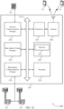
- FIG. 1 illustrates an example of a wireless communications system 100 in accordance with various aspects of the present disclosure.
- the wireless communications system 100 includes base stations 105, UEs 115, and a core network 130.
- the wireless communications system 100 may be an LTE, LTE-Advanced (LTE-A) network, or an NR network.
- LTE-A LTE-Advanced
- NR NR network.
- wireless communications system 100 may support enhanced broadband communications, ultra-reliable (e.g., mission critical) communications, low latency communications, and communications with low-cost and low-complexity devices.
- Wireless communications system 100 may provide for wireless transmissions in which uplink TTIs and downlink TTIs may be asymmetric, with various transmissions and timings based on one or both of the uplink or downlink TTI length.
- Base stations 105 may wirelessly communicate with UEs 115 via one or more base station antennas. Each base station 105 may provide communication coverage for a respective geographic coverage area 110.
- Communication links 125 shown in wireless communications system 100 may include uplink transmissions from a UE 115 to a base station 105, or downlink transmissions, from a base station 105 to a UE 115.
- Control information and data may be multiplexed on an uplink channel or downlink according to various techniques. Control information and data may be multiplexed on a downlink channel, for example, using time division multiplexing (TDM) techniques, frequency division multiplexing (FDM) techniques, or hybrid TDM-FDM techniques.
- TDM time division multiplexing
- FDM frequency division multiplexing
- hybrid TDM-FDM techniques hybrid TDM-FDM techniques.
- the control information transmitted during a TTI of a downlink channel may be distributed between different control regions in a cascaded manner (e.g., between a common control region and one or more
- UEs 115 may be dispersed throughout the wireless communications system 100, and each UE 115 may be stationary or mobile.
- a UE 115 may also be referred to as a mobile station, a subscriber station, a mobile unit, a subscriber unit, a wireless unit, a remote unit, a mobile device, a wireless device, a wireless communications device, a remote device, a mobile subscriber station, an access terminal, a mobile terminal, a wireless terminal, a remote terminal, a handset, a user agent, a mobile client, a client, or some other suitable terminology.
- a UE 115 may also be a cellular phone, a personal digital assistant (PDA), a wireless modem, a wireless communication device, a handheld device, a tablet computer, a laptop computer, a cordless phone, a personal electronic device, a handheld device, a personal computer, a wireless local loop (WLL) station, an Internet of things (IoT) device, an Internet of Everything (IoE) device, an MTC device, an appliance, an automobile, or the like.
- PDA personal digital assistant
- WLL wireless local loop
- IoT Internet of things
- IoE Internet of Everything
- a UE 115 may also be able to communicate directly with other UEs (e.g., using a peer-to-peer (P2P) or device-to-device (D2D) protocol).
- P2P peer-to-peer
- D2D device-to-device
- One or more of a group of UEs 115 utilizing D2D communications may be within the coverage area 110 of a cell. Other UEs 115 in such a group may be outside the coverage area 110 of a cell, or otherwise unable to receive transmissions from a base station 105.
- groups of UEs 115 communicating via D2D communications may utilize a one-to-many (1:M) system in which each UE 115 transmits to every other UE 115 in the group.
- a base station 105 facilitates the scheduling of resources for D2D communications.
- D2D communications are carried out independent of a base station 105.
- Some UEs 115 may be low cost or low complexity devices, and may provide for automated communication between machines, i.e., Machine-to-Machine (M2M) communication.
- M2M or MTC may refer to data communication technologies that allow devices to communicate with one another or a base station without human intervention.
- M2M or MTC may refer to communications from devices that integrate sensors or meters to measure or capture information and relay that information to a central server or application program that can make use of the information or present the information to humans interacting with the program or application.
- Some UEs 115 may be designed to collect information or enable automated behavior of machines. Examples of applications for MTC devices include smart metering, inventory monitoring, water level monitoring, equipment monitoring, healthcare monitoring, wildlife monitoring, weather and geological event monitoring, fleet management and tracking, remote security sensing, physical access control, and transaction-based business charging.
- an MTC device may operate using half-duplex (one-way) communications at a reduced peak rate. MTC devices may also be configured to enter a power saving "deep sleep" mode when not engaging in active communications. In some cases, MTC or IoT devices may be designed to support mission critical functions and wireless communications system may be configured to provide ultra-reliable communications for these functions.
- Base stations 105 may communicate with the core network 130 and with one another. For example, base stations 105 may interface with the core network 130 through backhaul links 132 (e.g., S1, etc.). Base stations 105 may communicate with one another over backhaul links 134 (e.g., X2, etc.) either directly or indirectly (e.g., through core network 130). Base stations 105 may perform radio configuration and scheduling for communication with UEs 115, or may operate under the control of a base station controller (not shown). In some examples, base stations 105 may be macro cells, small cells, hot spots, or the like. Base stations 105 may also be referred to as eNodeBs (eNBs) 105.
- eNodeBs eNodeBs
- a base station 105 may be connected by an S1 interface to the core network 130.
- the core network may be an evolved packet core (EPC), which may include at least one mobility management entity (MME), at least one serving gateway (S-GW), and at least one packet data network (PDN) gateway (P-GW).
- EPC evolved packet core
- MME mobility management entity
- S-GW serving gateway
- P-GW packet data network gateway
- IP Internet Protocol
- All user Internet Protocol (IP) packets may be transferred through the S-GW, which itself may be connected to the P-GW.
- the P-GW may provide IP address allocation as well as other functions.
- the P-GW may be connected to the network operators IP services.
- the operators IP services may include the Internet, the Intranet, an IP Multimedia Subsystem (IMS), and a Packet-Switched (PS) Streaming Service (PSS).
- IMS IP Multimedia Subsystem
- PSS Packet-Switched
- the core network 130 may provide user authentication, access authorization, tracking, IP connectivity, and other access, routing, or mobility functions.
- the network devices such as a base station 105 may include subcomponents such as an access network entity, which may be an example of an access node controller (ANC).
- ANC access node controller
- Each access network entity may communicate with a number of UEs 115 through one or more access network transmission entities, each of which may be an example of a smart radio head, or a transmission reception point (TRP).
- TRP transmission reception point
- various functions of each access network entity or base station 105 may be distributed across various network devices (e.g., radio heads and access network controllers) or consolidated into a single network device (e.g., a base station 105).
- Wireless communications system 100 may operate in an ultra high frequency (UHF) frequency region using frequency bands from 700 MHz to 2600 MHz (2.6 GHz), although in some cases, a wireless local area network (WLAN) may use frequencies as high as 4 GHz. This region may also be known as the decimeter band, since the wavelengths range from approximately one decimeter to one meter in length.
- UHF waves may propagate mainly by line of sight, and may be blocked by buildings and environmental features. However, the waves may penetrate walls sufficiently to provide service to UEs 115 located indoors. Transmission of UHF waves is characterized by smaller antennas and shorter range (e.g., less than 100 km) compared to transmission using the smaller frequencies (and longer waves) of the high frequency (HF) or very high frequency (VHF) portion of the spectrum.
- UHF high frequency
- VHF very high frequency
- wireless communications system 100 may also utilize extremely high frequency (EHF) portions of the spectrum (e.g., from 30 GHz to 300 GHz). This region may also be known as the millimeter band, since the wavelengths range from approximately one millimeter to one centimeter in length.
- EHF antennas may be even smaller and more closely spaced than UHF antennas. In some cases, this may facilitate use of antenna arrays within a UE 115 (e.g., for directional beamforming).
- wireless communications system 100 may be a packet-based network that operate according to a layered protocol stack.
- communications at the bearer or packet data convergence protocol (PDCP) layer may be IP-based.
- a radio link control (RLC) layer may in some cases perform packet segmentation and reassembly to communicate over logical channels.
- RLC radio link control
- a Medium Access Control (MAC) layer may perform priority handling and multiplexing of logical channels into transport channels.
- the MAC layer may also use HARQ to provide retransmission at the MAC layer to improve link efficiency.
- the radio resource control (RRC) protocol layer may provide establishment, configuration, and maintenance of an RRC connection between a UE 115 and a network device such as a base station 105 or core network 130 supporting radio bearers for user plane data.
- RRC radio resource control
- PHY Physical
- SFN system frame number
- Each frame may include ten 1 ms subframes numbered from 0 to 9.
- a subframe may be further divided into two .5ms slots, each of which contains 6 or 7 modulation symbol periods (depending on the length of the cyclic prefix prepended to each symbol). Excluding the cyclic prefix, each symbol contains 2048 sample periods.
- the subframe may be the smallest scheduling unit, also known as a TTI.
- a TTI may be shorter than a subframe or may be dynamically selected (e.g., in short TTI bursts or in selected component carriers using short TTIs).
- a resource element may consist of one symbol period and one subcarrier (e.g., a 15 kHz frequency range).
- a resource block may contain 12 consecutive subcarriers in the frequency domain and, for a normal cyclic prefix in each OFDM symbol, 7 consecutive OFDM symbols in the time domain (1 slot), or 84 resource elements.
- the number of bits carried by each resource element may depend on the modulation scheme (the configuration of symbols that may be selected during each symbol period, which may be referred to as a modulation and coding scheme (MCS)).
- MCS modulation and coding scheme
- Wireless communications system 100 may support operation on multiple cells or carriers, a feature which may be referred to as carrier aggregation (CA) or multi-carrier operation.
- a carrier may also be referred to as a CC, a layer, a channel, etc.
- the terms "carrier,” “component carrier,” “cell,” and “channel” may be used interchangeably herein.
- a UE 115 may be configured with multiple downlink CCs and one or more uplink CCs for carrier aggregation.
- Carrier aggregation may be used with both frequency division duplexing (FDD) and time division duplexing (TDD) component carriers.
- FDD frequency division duplexing
- TDD time division duplexing
- wireless communications system 100 may utilize enhanced component carriers (eCCs).
- eCC may be characterized by one or more features including: wider bandwidth, shorter symbol duration, shorter TTIs, and modified control channel configuration.
- an eCC may be associated with a carrier aggregation configuration or a dual connectivity configuration (e.g., when multiple serving cells have a suboptimal or non-ideal backhaul link).
- An eCC may also be configured for use in unlicensed spectrum or shared spectrum (where more than one operator is allowed to use the spectrum).
- An eCC characterized by wide bandwidth may include one or more segments that may be utilized by UEs 115 that are not capable of monitoring the whole bandwidth or prefer to use a limited bandwidth (e.g., to conserve power).
- an eCC may utilize a different symbol duration than other CCs, which may include use of a reduced symbol duration as compared with symbol durations of the other CCs.
- a shorter symbol duration may be associated with increased subcarrier spacing.
- a TTI in an eCC may consist of one or multiple symbols. In some cases, the TTI duration (that is, the number of symbols in a TTI) may be variable.
- wireless communications system 100 may utilize both licensed and unlicensed radio frequency spectrum bands.
- wireless communications system 100 may employ LTE License Assisted Access (LTE-LAA) or LTE Unlicensed (LTE U) radio access technology or NR technology in an unlicensed band such as the 5 GHz Industrial, Scientific, and Medical (ISM) band.
- LTE-LAA LTE License Assisted Access
- LTE U LTE Unlicensed
- NR NR technology
- an unlicensed band such as the 5 GHz Industrial, Scientific, and Medical (ISM) band.
- wireless devices such as base stations 105 and UEs 115 may employ listen-before-talk (LBT) procedures to ensure the channel is clear before transmitting data.
- LBT listen-before-talk
- operations in unlicensed bands may be based on a CA configuration in conjunction with CCs operating in a licensed band.
- Operations in unlicensed spectrum may include downlink transmissions, uplink transmissions, or both.
- Duplexing in unlicensed spectrum may be based on FDD,
- base stations 105 and UEs 115 may use a HARQ process to provide feedback (e.g., acknowledgment/negative-acknowledgment (ACK/NACK) feedback) of successful receipt of transmissions and to provide retransmissions in the event that a transmission is not successfully received.
- feedback e.g., acknowledgment/negative-acknowledgment (ACK/NACK) feedback
- Timings for generating and transmitting HARQ feedback and for generating and retransmitting unsuccessfully received transmissions may be based on pre-established rules for such timing between a reception TTI and a subsequent transmission. For example, an n+4 rule may be established in which the subsequent transmission is to be made four TTIs, or a first available TTI thereafter, following the reception TTI.
- a reception TTI is TTI-0
- the subsequent transmission would be made at TTI-4.
- various aspects of the present disclosure provide for techniques for determining timing and/or other parameters to account for the different TTI lengths for uplink and downlink transmissions. Such timing techniques may also be used for other timings as well, such as for timing between reception of downlink control information (DCI) and an associated uplink transmission, for example.
- DCI downlink control information
- a UE 115 may use a TA value that may compensate for propagation delay between when the UE 115 starts a transmission and when a base station 105 receives the transmission.
- the TA value is a negative offset, at the UE 115, between the start of a received downlink TTI and a transmitted uplink TTI. This offset at the UE 115 may help to ensure that the downlink and uplink TTI transmissions are synchronized at the base station 105.
- a UE 115 that is located relatively far from a serving base station 105 may encounter a larger propagation delay, so its uplink transmission is started earlier than another UE 115 that is closer to the same serving base station 105.
- maximum TA threshold values may be set to provide a UE 115 with sufficient processing time prior to the start of an uplink transmission.
- a TA value and maximum TA threshold value may be determined based in a TTI length of uplink or downlink transmissions, and one or more other parameters, such as a TBS, number of spatial layers, number of CCs, or CQI reporting type may be identified based at least in part on the TA value.
- FIG. 2 illustrates an example of a wireless communications system 200 for asymmetric downlink-uplink TTI configurations for low latency operation in accordance with various aspects of the present disclosure.
- Wireless communications system 200 includes base station 105-a and UE 115-a, which may be examples of aspects of a UE 115 as described above with reference to FIG. 1 .
- the wireless communications system 200 may operate according to a radio access technology (RAT) such as a 5G or NR RAT, although techniques described herein may be applied to any RAT and to systems that may concurrently use two or more different RATs.
- RAT radio access technology
- Base station 105-a may communicate with UE 115-a over an uplink carrier 205 and a downlink carrier 215.
- base station 105-a may allocate resources for communication with UEs 115 over uplink carrier 205 and downlink carrier 215.
- base station 105-a may allocate uplink subframes 210 in uplink carrier 205 for uplink transmissions from UE 115-a, and one or more uplink subframes 210 may correspond to a legacy LTE TTI of 1 ms.
- uplink subframes 210 may include a first uplink subframe 210-a, a second uplink subframe 210-b, and a third uplink subframe 210-c.
- Each of the uplink subframes 210 may include two slots, in which each slot may have seven OFDM symbols for a normal cyclic prefix.
- a first slot (slot 0) 225 and a second slot (slot 1) 230 may be included in the first uplink subframe 210-a.
- sTTI lengths may be used for transmissions over uplink carrier 205.
- two-symbol sTTI and 1-slot sTTI durations may be supported for physical uplink control channel (PUCCH) and physical uplink shared channel (PUSCH) transmissions (or shortened PUCCH (sPUCCH) and shortened PUSCH (sPUSCH) transmissions).
- PUCCH physical uplink control channel
- PUSCH physical uplink shared channel
- sPUSCH shortened PUCCH
- sPUSCH shortened PUSCH
- first slot 225 or second slot 230 there may be multiple sTTIs, such as a first sTTI (TTI-0) 235, a second sTTI (TTI-1) 240, and a third sTTI (TTI-2) 245, that may each have a two or three OFDM symbol duration.
- TTI durations may also apply to downlink subframes 220 transmitted on downlink carrier 215.
- different length TTIs may be used on the uplink carrier 205 and the downlink carrier 215, resulting in asymmetric TTI lengths for uplink and downlink transmissions.
- sTTI When a two-symbol sTTI is used, in some cases it may be desirable to have a fixed sTTI structure in which sTTI boundaries lie within slot boundaries or are aligned with slot boundaries, such as the boundaries of the first slot 225 or second slot 230, which may be referred to as slot-aligned sTTIs. As discussed above, when using a normal cyclic prefix, seven symbols are included in each of first slot and second slot 230, and thus each slot may include three sTTIs for slot-aligned sTTIs. In some cases, one of the sTTIs may be configured as a three-symbol TTI, so as to efficiently utilize each symbol of each slot.
- different patterns can be considered, such as having the three-symbol TTI located at the end of first slot 225 or second slot 230, or at the beginning of first slot 225 or second slot 230.
- sTTIs may be referred to as 2-symbol sTTIs.
- slot sTTIs When using sTTIs having a duration corresponding to one slot, such sTTIs may be referred to as slot sTTIs.
- TTIs having a duration correspond to a subframe, such TTIs may be referred to as 1 ms TTIs or legacy TTIs.
- a 2-symbol uplink transmission (such as PUCCH or sPUCCH) may not provide sufficient uplink coverage to provide reliable reception of the uplink transmissions.
- a longer sTTI e.g., a slot sPUCCH
- a 1 ms PUCCH may be employed for uplink transmissions.
- RTT round trip time
- the UE 115-a may be scheduled for a 2-symbol sTTI in a downlink transmission and may be configured to use either a 1-slot sPUCCH or a 1 ms PUCCH depending on its channel condition.
- the associated sPUCCH or PUCCH transmission may provide uplink information for multiple 2-symbol downlink sTTIs.
- 2-symbol downlink sTTIs may use a first pattern of symbols ⁇ 3,2,2,2,3 ⁇ for the two slots within a subframe boundary, or may use a second pattern of symbols ⁇ 2,3,2,2,2,3 ⁇ for such transmissions.
- the pattern to be used may be indicated in a physical control format indicator channel (PCFICH), in which a PCFICH value of 1 or 3 indicated the first pattern, and a PCFICH value of 2 indicates the second pattern.
- PCFICH physical control format indicator channel
- One of the following two patterns will also be specified for the uplink transmissions for 2-symbol sTTI transmissions: ⁇ 3,2,2,2,2,3 ⁇ or ⁇ 2,2,3,2,2,3 ⁇ .
- asymmetric uplink and downlink TTIs may be used, and this the timing for various transmissions may be determined based on one or more of the uplink TTI or downlink TTI.
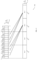
- FIG. 3 illustrates an example of asymmetric uplink and downlink TTIs 300 and associated timings for low latency operation, in accordance with various aspects of the disclosure.
- Asymmetric uplink and downlink TTIs 300 may be used for communications between a UE and a base station such as discussed above with respect to FIGs. 1 and 2 .
- downlink sTTIs 305 may be used for downlink transmissions from a base station to a UE, and be transmitted using the pattern ⁇ 3,2,2,2,2,3 ⁇ as discussed above.
- sTTI-0 315 may be a three-symbol sTTI
- sTTI-1 320 through sTTI-4 335 may be two-symbol sTTIs
- sTTI-5 340 and sTTI-6 345 may be three-symbol sTTIs in accordance with the downlink pattern.
- uplink sTTIs 310 may be used for uplink transmissions from the UE to the base station, and may have a longer TTI duration than downlink sTTIs 305.
- each of the uplink sTTIs 310 may be slot sTTIs, having a length that corresponds to a slot of a subframe.
- each slot sTTI 350 through 365 may have a duration that corresponds to seven OFDM symbols, and downlink sTTIs 305 and uplink sTTIs 310 may be slot-aligned.
- Such a configuration of asymmetric uplink and downlink TTIs may be referred to as a ⁇ 2,7 ⁇ configuration, with a 2-symbol sTTI for downlink transmissions and a slot sTTI (7 symbols) for uplink transmissions.
- Other configurations may be referred to using such a nomenclature, with ⁇ 2,2 ⁇ referring to 2-symbol sTTIs for both uplink and downlink, ⁇ 2,14 ⁇ referring to 2-symbol downlink and 1 ms uplink TTIs, and ⁇ 7,14 ⁇ referring to slot sTTI downlink and 1 ms uplink TTIs.
- the ACK/NACK transmission may be transmitted during a TTI that with the relationship n + 4 following the TTI in which a transmission is received. That is, for a downlink reception in TTI n , ACK/NACK feedback is to be transmitted at or after TTI n + 4 .
- ACK/NACK feedback information from multiple downlink sTTIs 305 may be reported in one uplink sTTI 310.
- the TTI length associated with downlink sTTIs 305 may be used to determine an uplink sTTI 310 that is to be used for transmitting ACK/NACK feedback, and ACK/NACK feedback for each downlink sTTI 305 in a slot may be reported in an uplink sTTI 310.
- the sTTI associated with the last downlink transmission is used as TTI n, which corresponds to sTTI-2 325 in this example.
- n + 4 Using a 2-symbol sTTI as the sTTI length, the value of n + 4 would result in a start time for the subsequent ACK/NACK transmission beginning at the last symbol of slot1 355, and with the sTTI associated with n + 4 spanning to the first symbol of slot2 360. In such cases, the start time of the subsequent transmission may be shifted to start at the beginning of slot2 360, and the ACK/NACK feedback for sTTI-0 315 through sTTI-2 may be reported in sPUCCH transmissions that are transmitted in the uplink sTTI corresponding to slot2 360. Similarly, the ACK/NACK feedback for downlink sTTIs 305 corresponding to slot1 355 may be transmitted in slot3 365.
- a UE groups ACK/NACK feedback across subframe boundaries and transmit the grouped feedback information according to a transmission timing associated with the sTTIs in the earlier subframe. For example, sTTIs within slot-2 360 (of subframe N ) may be grouped with sTTIs within slot-1 355 (of subframe N - 1 ) and HARQ ACK/NACK feedback may be transmitted to the base station in slot 0 (subframe N + 1) . Such grouping in this configuration provides a sufficient symbol gap for processing both at the UE and at the base station. Based on the n + 4 timing rule when n is the 2-symbol sTTI duration, this gap may be sufficient.
- the HARQ ACK/NAK of sTTI-4 and sTTI-5 of subframe N - 1 and sTTI-0 of subframe N will be mapped to uplink slot 0 of subframe N + 1.
- an uplink grant (e.g., received via a downlink sTTI 305) and a uplink transmission (e.g., for transmission via an sPUSCH in an uplink sTTI 310).
- an uplink grant for slot 0 in subframe 4 may be sent in sTTI-4 of subframe 1, sTTI-5 of subframe 1, or sTTI-0 of subframe 2.
- An uplink grant for slot 1 in subframe 4 may be transmitted in sTTI-1, sTTI-2, or sTTI-3 of subframe 2. In such cases, this may allow sufficient time for processing the uplink grant received in a downlink sTTI 305 before transmitting in an uplink sTTI 310.
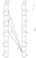
- FIG. 4 illustrates an example of symmetric uplink and downlink TTIs 400 with grouping for low latency operation in accordance with various aspects of the present disclosure.
- Symmetric uplink and downlink TTIs 400 may be used for communications between a UE and a base station such as discussed above with respect to FIGs. 1 and 2 .
- downlink sTTIs 405 may be used for downlink transmissions from a base station to a UE, and be transmitted using the pattern ⁇ 3,2,2,2,2,3 ⁇ as discussed above.
- Uplink sTTIs 410 may be used for uplink transmissions from a UE to a base station, and be transmitted using the pattern ⁇ 3,2,2,2,2,3 ⁇ as discussed above.
- downlink sTTIs 405 may include a three-symbol sTTI-0 415, sTTI-1 420 through sTTI-4 435 may be two-symbol sTTIs, and sTTI-5 440 and sTTI-6 445 may be three-symbol sTTIs in accordance with the downlink pattern.
- the uplink sTTIs 410 may have a same ⁇ 3,2,2,2,3 ⁇ pattern, although the techniques as described herein are applicable in cases where the uplink sTTIs 410 have a different pattern than the downlink sTTIs 405.
- Such a configuration of uplink and downlink TTIs may be referred to as a ⁇ 2,2 ⁇ configuration, with a 2-symbol sTTI for downlink and uplink transmissions.
- the ACK/NACK transmission may be transmitted during a TTI that with the relationship n +4 following the TTI in which a transmission is received.
- ACK/NACK feedback is to be transmitted at or after TTI n + 4 , which corresponds to uplink sTTI- 4 450.
- ACK/NACK feedback for downlink sTTI-1 420 may be transmitted in uplink sTTI-5 455, and ACK/NACK feedback for downlink sTTI-2 425 may be transmitted in uplink sTTI-6 460.
- the uplink sTTI-6 460 is a three-symbol sTTI
- the subsequent ACK/NACK transmission for downlink sTTI-3 430 would start in the last symbol of uplink sTTI-6 460, and thus the transmission of the ACK/NACK transmission for downlink sTTI-3 430 may be time shifted to align with uplink sTTI-7 465.
- ACK/NACK transmission for downlink sTTI-4 435 may align with uplink sTTI-7 465.
- ACK/NACK feedback for downlink sTTI-5 440 may be transmitted in uplink sTTI-9 475, with uplink sTTI-8 470 not carrying any HARQ ACK/NACK feedback information.
- the combined ACK/NACK feedback may be coded, such as according to a Turbo coding scheme or a RM coding scheme, for example.
- the average downlink HARQ delay is 6.66 symbols if a ⁇ 2,2 ⁇ configuration is assumed, and 9.33 symbols if a ⁇ 2,7 ⁇ configuration is assumed.
- the price of using a longer sTTI length in the uplink is increasing the downlink HARQ timing by about 190 microseconds ( ⁇ s), and thus increasing the overall RTT and latency relative to the ⁇ 2,2 ⁇ configuration.
- an increased uplink TTI length may be selected based on channel conditions. As channel conditions worsen, the likelihood for HARQ retransmissions increases, which may also impact latency in the system.
- the TTI length for uplink transmissions may be selected based at least in part on channel conditions, in which a longer uplink TTI may be selected when the associated increase in HARQ timing provides an overall benefit when taking into account an expected rate of retransmissions for relatively poor channel conditions.
- a base station may receive CQI information from a UE and may configure the UE for particular TTI durations based at least in part on the CQI.
- FIG. 5 illustrates an example of feedback reception to transmission or retransmission timing 500 for asymmetric downlink-uplink TTI configurations for low latency operation in accordance with various aspects of the present disclosure.
- Uplink and downlink transmission time intervals 500 may be used for communications between a UE and a base station such as discussed above with respect to FIGs. 1 and 2 .
- downlink sTTIs 505 may be used for downlink transmissions for a UE to a base station, and may include 1 ms TTIs, 2-symbol sTTIs or slot sTTIs.
- downlink slot n 515 through downlink slot n+4 are illustrated, along with uplink slot n 540 through uplink slot n+4 560.
- uplink sTTIs 510 may be slot sTTIs, and HARQ ACK/NACK feedback may be received by a base station from a UE during uplink slot n 565.
- the base station may process the AKC/NACK feedback and determine if a previous transmission is to be retransmitted, or if a new transmission may be transmitted, responsive to the ACK/NACK feedback. If the downlink sTTIs 505 have a length of a slot sTTI or 1 ms TTI, then the ACK/NAK to transmission/retransmission timing could be based on the n+4 rule, as indicated at arrow 565 is this example. In other cases, the downlink sTTIs 505 may be 2-symbol sTTIs, and the base station may prepare a new transmission or a retransmission more quickly than is the downlink sTTIs 505 were longer.
- the ACK/NAK to transmission/retransmission timing may be computed as a function of the uplink sTTI length, but under shortened processing time, e.g., n + 3 or n+2 as shown in the figure at arrow 570 and arrow 575, respectively.
- the processing timing at the base station may be based on the downlink TTI length or the uplink TTI length.
- the timing could be n + 2, n + 3 or n + 4, where n is the duration of the uplink TTI.
- the timing choice may be n + Z where n is the duration of the uplink TTI.
- a ⁇ 2,7 ⁇ configuration if the base station processing is based on n + 2 and slot duration, there will be 7 symbol gap between the ACK/NACK feedback reception and transmission/retransmission.
- a ⁇ 2,14 ⁇ configuration if the base station processing is based on n + 2 and 1 ms duration, there will be a 14 symbol gap between the ACK/NACK feedback reception and transmission/retransmission.
- processing timing at the base station may be based on the downlink TTI length, and n + k timing may be used (e.g., where k ⁇ 4 and n is the 2-symbol sTTI length), and thus the processing timing is based on the downlink sTTI length.
- the transmission/retransmission is not necessarily aligned with either the slot or subframe boundaries, and may be initiated based on the n + k timing. As an example, if the 7-symbol or the 14-symbol gap discussed above are not sufficient, or if more flexibility is desired in terms of the retransmission timings, this option may be selected.
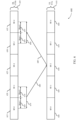
- FIG. 6 illustrates an example of feedback bundling across subframe boundaries 600 for asymmetric downlink-uplink TTI configurations for low latency operation in accordance with various aspects of the present disclosure.
- Feedback bundling across subframe boundaries 600 may be used for communications between a UE and a base station such as discussed above with respect to FIGs. 1 and 2 .
- downlink sTTIs 605 may be slot-aligned sTTIs used for downlink transmissions for a UE to a base station, and may include 2-symbol sTTIs.
- downlink subframe boundaries are illustrated for downlink subframe-0 615 through downlink subframe-4 635, along with uplink subframe-0 640 through uplink subframe-4 660.
- uplink TTIs 610 may be 1 ms TTIs.
- a UE groups ACK/NACK feedback across subframe boundaries and transmit the grouped feedback information according to a transmission timing associated with the sTTIs in the earlier subframe. For example, sTTIs within slot-1 665 of subframe-0 615 may be grouped with sTTIs within slot-0 670 of subframe-1 620 to generate feedback for a time period 675 that spans a subframe boundary, and HARQ ACK/NACK feedback 680 may be transmitted to the base station in uplink subframe-2 650.
- Such grouping in this configuration provides a 7-symbol gap for processing both at the UE and at the base station. Based on the n + 4 timing rule when n is the 2-symbol sTTI duration, this gap may be sufficient.
- the base station may process the ACK/NACK feedback and determine if a previous transmission is to be retransmitted, or if a new transmission may be transmitted, responsive to the ACK/NACK feedback.
- the new transmissions and/or retransmissions 685 may be transmitted in time period 690 that spans slot-1 695 of subframe-3 630 and in slot-0 697 of subframe-4 635.
- FIG. 7 illustrates an example of a process flow 700 for asymmetric downlink-uplink TTI configurations for low latency operation in accordance with various aspects of the present disclosure.
- Process flow 700 may include a base station 105-b, and a UE 115-b, which may be examples of the corresponding devices described with reference to FIG. 1-2 .
- the base station 105-b and the UE 115-b may establish a connection 705 according to connection establishment techniques for the wireless communications system.
- base station 105-b may configure the UE 115-b according to uplink and downlink TTI lengths. For example, the base station 105-b may determine that the UE 115-b may operate using low latency communications and may configure the UE 115-b to use sTTIs when low-latency data (e.g., URLLC data or MiCr data) is to be transmitted. In some cases, the base station 105-b may identify uplink channel conditions that may support certain TTI lengths and configure the UE 115-b for sTTI transmissions based on the channel conditions at the UE 115-b. The base station 105-b may transmit the configuration information 715 to the UE 115-b.
- low-latency data e.g., URLLC data or MiCr data
- the base station 105-b may identify uplink and downlink TTI lengths for one or more transmissions.
- the base station 105-b may, for example, identify that the UE 115-b is capable of low-latency communications using sTTIs and that the UE 115-b has been configured for sTTI transmissions.
- the base station 105-b may identify that low-latency data is present for transmission, such as based on a buffer status report (BSR) provided by the UE 115-b or buffered data to be transmitted to the UE 115-b, for example.
- BSR buffer status report
- the base station 105-b may determine that channel conditions at the UE 115-b may indicate that a longer uplink TTI length may improve coverage for the UE 115-b, and identify a longer uplink TTI length than the downlink TTI length.
- the base station 105-b may determine HARQ timing based on the uplink or downlink TTI length. For example, HARQ timing may be based on the downlink TTI length when the downlink TTI length is shorter than the uplink TTI length, as discussed above. In some examples, the base station 105-b may determine a timing for a HARQ retransmission or a new transmission following receipt of feedback information from the UE 115-b, which may be based on the downlink TTI length or the uplink TTI length, as discussed above. The base station 105-b may transmit downlink transmissions 730 using downlink TTIs having the determined downlink TTI length
- the UE 115-b may identify the uplink and downlink TTI lengths.
- the UE 115-b may make such an identification based on configuration information from the base station 105-b, a service associated with data to be transmitted, channel conditions at the UE, or PCFICH information, for example.
- the UE 115-b may identify that the uplink TTI length is different than the downlink TTI length, as discussed above.
- the UE 115-b may determine HARQ timing and a TA value based on the uplink TTI length, the downlink TTI length, or combinations thereof.
- the downlink TTI length may be shorter than the uplink TTI length, and HARQ timing and the TA value may be determined based in the downlink TTI length, as discussed above.
- a maximum TA value may also be determined based on the uplink TTI length and/or the downlink TTI length.
- the downlink HARQ timing man be based on n + k 1 , where, for example n may be the downlink sTTI index and k 1 may be counted in terms of the number of downlink TTIs (e.g., k 1 ⁇ 4). In some cases, a certain time shift may be applied so that the uplink transmission is aligned with uplink TTI boundaries.
- the downlink HARQ timing can be based on n + k 1 , where n is the downlink sTTI index and k 1 may be counted in terms of the number of downlink TTIs (e.g., k 1 ⁇ 4). A certain time shift may be applied as needed so that the uplink transmission is aligned with the uplink TTI boundaries.
- the ACK/NAK to transmission/retransmission timing may be based on n + k 2 , where n is the downlink TTI index and k 2 may be counted in terms of the number of downlink TTIs (e.g., k 2 ⁇ 4). Again, a certain time shift may be applied so that the downlink transmission is aligned with the downlink sTTI boundaries.
- k 1 and k 2 may be identical, or may not be identical.
- sTTIs of a second slot of a subframe n and the first slot of a subsequent subframe n + 1 can be grouped, and the processing timing at both the UE 115-b and the base station 105-b may be based on the n + k rule.
- a TA value and processing timing may be determined based on one or more of the uplink TTI length or the downlink TTI length.
- a maximum TA value may be set based on the downlink sTTI length or the uplink TTI length. In some examples, even if PUCCH uses a longer TTI length (e.g., in the case of ⁇ 2,7 ⁇ or ⁇ 2,14 ⁇ configuration), the maximum TA may be based on the downlink sTTI length.
- one or more other parameters may be dependent on the maximum TA value, such as TBS, number of spatial layers, number of CCs, or CQI reporting, for example, may also be devised based on the downlink sTTI length.
- a relatively longer PUCCH requires more time for transmission preparation.
- a slot sPUCCH or 1 ms PUCCH may need to provide ACK/NACK information for multiple downlink sTTIs, and may have to handle multiple ACK/NAK bits.
- RM coding or Turbo coding may be used for sPUCCH transmissions, such as based on PUCCH format 3.
- Such a longer uplink TTI length may be chosen if the UE 115-b has relatively poor coverage.
- the TA value may be set based on the longer uplink sTTI/TTI length.
- the processing timing can also be based on this TA value. For example, for a ⁇ 2,2 ⁇ configuration, an n + 4 timing may be used with TA1, while for ⁇ 2,7 ⁇ configuration, a n + 6 or n + 7 timing may be used with TA2, where TA2 > TA1.
- the UE 115-b may transmit uplink transmissions 745 to the base station 105-b based on the uplink TTI length.
- the uplink transmissions 745 may include feedback information based on the timing from the downlink transmissions 730.
- the base station may perform received signal processing. For example, the base station 105-b may process ACK/NACK feedback information and determine whether a retransmission of certain data is needed, and format a new transmission or the retransmission 755 for downlink transmission in a subsequent downlink TTI based on the timing between feedback reception and transmission or retransmission.
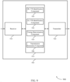
- FIG. 8 shows a block diagram 800 of a wireless device 805 that supports asymmetric downlink-uplink TTI configurations for low latency operation in accordance with various aspects of the present disclosure.
- Wireless device 805 may be an example of aspects of a UE 115 or base station 105 as described with reference to FIG. 1 .
- Wireless device 805 may include receiver 810, timing manager 815, and transmitter 820.
- Wireless device 805 may also include a processor. Each of these components may be in communication with one another (e.g., via one or more buses).
- Receiver 810 may receive information such as packets, user data, or control information associated with various information channels (e.g., control channels, data channels, and information related to asymmetric downlink-uplink TTI configurations for low latency operation, etc.). Information may be passed on to other components of the device.
- the receiver 810 may be an example of aspects of the transceiver 1135 described with reference to FIG. 11 .
- Timing manager 815 may be an example of aspects of the UE timing manager 1115 or a base station timing manager 1215 as described with reference to FIGs. 11 and 12 .
- Timing manager 815 and/or at least some of its various sub-components may be implemented in hardware, software executed by a processor, firmware, or any combination thereof. If implemented in software executed by a processor, the functions of the timing manager 815 and/or at least some of its various sub-components may be executed by a general-purpose processor, a digital signal processor (DSP), an application-specific integrated circuit (ASIC), an field-programmable gate array (FPGA) or other programmable logic device, discrete gate or transistor logic, discrete hardware components, or any combination thereof designed to perform the functions described in the present disclosure.
- DSP digital signal processor
- ASIC application-specific integrated circuit
- FPGA field-programmable gate array
- timing manager 815 and/or at least some of its various sub-components may be physically located at various positions, including being distributed such that portions of functions are implemented at different physical locations by one or more physical devices.
- timing manager 815 and/or at least some of its various sub-components may be a separate and distinct component in accordance with various aspects of the present disclosure.
- timing manager 815 and/or at least some of its various sub-components may be combined with one or more other hardware components, including but not limited to an I/O component, a transceiver, a network server, another computing device, one or more other components described in the present disclosure, or a combination thereof in accordance with various aspects of the present disclosure.
- Timing manager 815 may identify a first TTI length for downlink transmissions, identify a second TTI length for uplink transmissions, the second TTI length being different than the first TTI length, determine one or more of a feedback process transmission timing or a TA value based on one or more of the first TTI length or the second TTI length, and transmit a subsequent transmission according to one or more of the feedback process transmission timing or the TA value.
- Transmitter 820 may transmit signals generated by other components of the device.
- the transmitter 820 may be collocated with a receiver 810 in a transceiver module.
- the transmitter 820 may be an example of aspects of the transceiver 1135 described with reference to FIG. 11 .
- the transmitter 820 may include a single antenna, or it may include a set of antennas.
- FIG. 9 shows a block diagram 900 of a wireless device 905 that supports asymmetric downlink-uplink TTI configurations for low latency operation in accordance with various aspects of the present disclosure.
- Wireless device 905 may be an example of aspects of a wireless device 805 or a UE 115 or base station 105 as described with reference to FIGs. 1 and 8 .
- Wireless device 905 may include receiver 910, timing manager 915, and transmitter 920.
- Wireless device 905 may also include a processor. Each of these components may be in communication with one another (e.g., via one or more buses).
- Receiver 910 may receive information such as packets, user data, or control information associated with various information channels (e.g., control channels, data channels, and information related to asymmetric downlink-uplink TTI configurations for low latency operation, etc.). Information may be passed on to other components of the device.
- the receiver 910 may be an example of aspects of the transceiver 1135 described with reference to FIG. 11 .
- Timing manager 915 may be an example of aspects of the UE timing manager 1115 or a base station timing manager 1215 as described with reference to FIGs. 11 and 12 .
- Timing manager 915 may also include downlink TTI identification component 925, uplink TTI identification component 930, timing determination component 935, and transmission generation component 940.
- downlink TTI identification component 925 may identify a first TTI length for downlink transmissions.
- uplink TTI identification component 930 may identify a second TTI length for uplink transmissions, the second TTI length being different than the first TTI length.
- Timing determination component 935 may determine one or more of a feedback process transmission timing or a TA value based on one or more of the first TTI length or the second TTI length. In some cases, timing determination component 935 may shift a start time for the subsequent transmission that includes a new transmission or retransmission to align with a start of a downlink TTI having the first TTI length. In some cases, a start time for the subsequent transmission is shifted to align with a start of an uplink TTI having the second TTI length. In some cases, the second TTI length is selected based on a channel condition for the uplink transmissions.
- Transmission generation component 940 may format a subsequent transmission according to one or more of the feedback process transmission timing or the TA value.
- Transmitter 920 may transmit signals generated by other components of the device.
- the transmitter 920 may be collocated with a receiver 910 in a transceiver module.
- the transmitter 920 may be an example of aspects of the transceiver 1135 described with reference to FIG. 11 .
- the transmitter 920 may include a single antenna, or it may include a set of antennas.
- FIG. 10 shows a block diagram 1000 of a timing manager 1015 that supports asymmetric downlink-uplink TTI configurations for low latency operation in accordance with various aspects of the present disclosure.
- the timing manager 1015 may be an example of aspects of a timing manager 815, a timing manager 915, a UE timing manager 1115, or a base station timing manager 1215, as described with reference to FIGs. 8 , 9 , 11 and 12 .
- the timing manager 1015 may include downlink TTI identification component 1020, uplink TTI identification component 1025, timing determination component 1030, transmission generation component 1035, HARQ component 1040, HARQ grouping component 1045, TA component 1050, and transmission parameter determination component 1055. Each of these modules may communicate, directly or indirectly, with one another (e.g., via one or more buses).
- DL TTI identification component 1020 may identify a first TTI length for downlink transmissions.
- uplink TTI identification component 1025 may identify a second TTI length for uplink transmissions, the second TTI length being different than the first TTI length.
- Timing determination component 1030 may determine one or more of a feedback process transmission timing or a TA value based on one or more of the first TTI length or the second TTI length and in some cases shift a start time for the subsequent transmission that includes the new transmission or retransmission to align with a start of a downlink TTI having the first TTI length. In some cases, a start time for the subsequent transmission is shifted to align with a start of an uplink TTI having the second TTI length. In some cases, the second TTI length is selected based on a channel condition for the uplink transmissions.
- Transmission generation component 1035 may transmit a subsequent transmission according to one or more of the feedback process transmission timing or the TA value.
- HARQ component 1040 determines a second HARQ feedback process timing for transmitting HARQ acknowledgement ACK/NACK feedback based on the first TTI length for downlink transmissions, and where the first HARQ process timing and the second HARQ process timing for starting the subsequent transmission are based on different integer numbers of first TTI lengths.
- a HARQ feedback process timing for transmitting ACK/NACK feedback in the subsequent transmission is determined based on the first TTI length for downlink transmissions.
- a HARQ process timing for transmitting a new transmission or a retransmission in the subsequent transmission is determined based on the second TTI length.
- a first HARQ process timing for transmitting a new transmission or a retransmission is determined based on the first TTI length.
- HARQ grouping component 1045 in cases where first TTI length is shorter than the second TTI length, groups ACK/NACK feedback for two or more downlink transmissions to be transmitted in a single subsequent transmission.
- the first TTI length is shorter than the second TTI length, and feedback information for two or more downlink transmissions is grouped for transmission in the subsequent transmission.
- the two or more downlink transmissions are in different subframes and the feedback information is grouped across the different subframes.
- the grouped feedback information is coded for transmission in the subsequent transmission according to a Reed-Muller (RM) coding technique or a turbo coding technique.
- RM Reed-Muller
- TA component 1050 may determine the TA value for the subsequent transmission based on the first TTI length. In some cases, the TA value for the subsequent transmission is determined based on the second TTI length. In some cases, a HARQ process timing or a timing between an uplink grant and the uplink transmissions is determined based on the TA value.
- Transmission parameter determination component 1055 may determine, in some cases, one or more parameters for the subsequent transmission based on the first TTI length.
- the one or more parameters for the subsequent transmission include one or more of a TBS, a number of spatial layers for the subsequent transmission, a number of CCs to carry the subsequent transmission, or a CQI reporting type.
- FIG. 11 shows a diagram of a system 1100 including a device 1105 that supports asymmetric downlink-uplink TTI configurations for low latency operation in accordance with various aspects of the present disclosure.
- Device 1105 may be an example of or include the components of wireless device 805, wireless device 905, or a UE 115 as described above, e.g., with reference to FIGs. 1 , 8 and 9 .
- Device 1105 may include components for bi-directional voice and data communications including components for transmitting and receiving communications, including UE timing manager 1115, processor 1120, memory 1125, software 1130, transceiver 1135, antenna 1140, and I/O controller 1145. These components may be in electronic communication via one or more busses (e.g., bus 1110).
- Device 1105 may communicate wirelessly with one or more base stations 105.
- Processor 1120 may include an intelligent hardware device, (e.g., a general-purpose processor, a DSP, a central processing unit (CPU), a microcontroller, an ASIC, an FPGA, a programmable logic device, a discrete gate or transistor logic component, a discrete hardware component, or any combination thereof).
- processor 1120 may be configured to operate a memory array using a memory controller.
- a memory controller may be integrated into processor 1120.
- Processor 1120 may be configured to execute computer-readable instructions stored in a memory to perform various functions (e.g., functions or tasks supporting asymmetric downlink-uplink TTI configurations for low latency operation).
- Memory 1125 may include random access memory (RAM) and read only memory (ROM).
- RAM random access memory
- ROM read only memory
- the memory 1125 may store computer-readable, computer-executable software 1130 including instructions that, when executed, cause the processor to perform various functions described herein.
- the memory 1125 may contain, among other things, a basic input/output system (BIOS) which may control basic hardware and/or software operation such as the interaction with peripheral components or devices.
- BIOS basic input/output system
- Software 1130 may include code to implement aspects of the present disclosure, including code to support asymmetric downlink-uplink TTI configurations for low latency operation.
- Software 1130 may be stored in a non-transitory computer-readable medium such as system memory or other memory. In some cases, the software 1130 may not be directly executable by the processor but may cause a computer (e.g., when compiled and executed) to perform functions described herein.
- Transceiver 1135 may communicate bi-directionally, via one or more antennas, wired, or wireless links as described above.
- the transceiver 1135 may represent a wireless transceiver and may communicate bi-directionally with another wireless transceiver.
- the transceiver 1135 may also include a modem to modulate the packets and provide the modulated packets to the antennas for transmission, and to demodulate packets received from the antennas.
- the wireless device may include a single antenna 1140. However, in some cases the device may have more than one antenna 1140, which may be capable of concurrently transmitting or receiving multiple wireless transmissions.
- I/O controller 1145 may manage input and output signals for device 1105. I/O controller 1145 may also manage peripherals not integrated into device 1105. In some cases, I/O controller 1145 may represent a physical connection or port to an external peripheral. In some cases, I/O controller 1145 may utilize an operating system such as iOS ® , ANDROID ® , MS-DOS ® , MS-WINDOWS ® , OS/2 ® , UNIX ® , LINUX ® , or another known operating system. In other cases, I/O controller 1145 may represent or interact with a modem, a keyboard, a mouse, a touchscreen, or a similar device. In some cases, I/O controller 1145 may be implemented as part of a processor. In some cases, a user may interact with device 1105 via I/O controller 1145 or via hardware components controlled by I/O controller 1145.
- FIG. 12 shows a diagram of a system 1200 including a device 1205 that supports asymmetric downlink-uplink TTI configurations for low latency operation in accordance with various aspects of the present disclosure.
- Device 1205 may be an example of or include the components of wireless device 905, wireless device 1105, or a base station 105 as described above, e.g., with reference to FIGs. 1 , 9 , and 11 .
- Device 1205 may include components for bi-directional voice and data communications including components for transmitting and receiving communications, including base station timing manager 1215, processor 1220, memory 1225, software 1230, transceiver 1235, antenna 1240, network communications manager 1245, and base station communications manager 1250. These components may be in electronic communication via one or more busses (e.g., bus 1210).
- Device 1205 may communicate wirelessly with one or more UEs 115.
- Processor 1220 may include an intelligent hardware device, (e.g., a general-purpose processor, a DSP, a CPU, a microcontroller, an ASIC, an FPGA, a programmable logic device, a discrete gate or transistor logic component, a discrete hardware component, or any combination thereof).
- processor 1220 may be configured to operate a memory array using a memory controller.
- a memory controller may be integrated into processor 1220.
- Processor 1220 may be configured to execute computer-readable instructions stored in a memory to perform various functions (e.g., functions or tasks supporting asymmetric downlink-uplink TTI configurations for low latency operation).
- Memory 1225 may include RAM and ROM.
- the memory 1225 may store computer-readable, computer-executable software 1230 including instructions that, when executed, cause the processor to perform various functions described herein.
- the memory 1225 may contain, among other things, a BIOS which may control basic hardware and/or software operation such as the interaction with peripheral components or devices.
- Software 1230 may include code to implement aspects of the present disclosure, including code to support asymmetric downlink-uplink TTI configurations for low latency operation.
- Software 1230 may be stored in a non-transitory computer-readable medium such as system memory or other memory. In some cases, the software 1230 may not be directly executable by the processor but may cause a computer (e.g., when compiled and executed) to perform functions described herein.
- Transceiver 1235 may communicate bi-directionally, via one or more antennas, wired, or wireless links as described above.
- the transceiver 1235 may represent a wireless transceiver and may communicate bi-directionally with another wireless transceiver.
- the transceiver 1235 may also include a modem to modulate the packets and provide the modulated packets to the antennas for transmission, and to demodulate packets received from the antennas.
- the wireless device may include a single antenna 1240. However, in some cases the device may have more than one antenna 1240, which may be capable of concurrently transmitting or receiving multiple wireless transmissions.
- Network communications manager 1245 may manage communications with the core network (e.g., via one or more wired backhaul links). For example, the network communications manager 1245 may manage the transfer of data communications for client devices, such as one or more UEs 115.
- Base station communications manager 1250 may manage communications with other base station 105, and may include a controller or scheduler for controlling communications with UEs 115 in cooperation with other base stations 105. For example, the base station communications manager 1250 may coordinate scheduling for transmissions to UEs 115 for various interference mitigation techniques such as beamforming or joint transmission. In some examples, base station communications manager 1250 may provide an X2 interface within an Long Term Evolution (LTE)/LTE-A wireless communication network technology to provide communication between base stations 105.
- LTE Long Term Evolution
- LTE-A wireless communication network technology to provide communication between base stations 105.
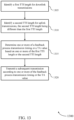
- FIG. 13 shows a flowchart illustrating a method 1300 for asymmetric downlink-uplink TTI configurations for low latency operation in accordance with various aspects of the present disclosure.
- the operations of method 1300 may be implemented by a UE 115 or base station 105 or its components as described herein.
- the operations of method 1300 may be performed by a timing manager as described with reference to FIGs. 8 through 10 .
- a UE 115 or base station 105 may execute a set of codes to control the functional elements of the device to perform the functions described below. Additionally or alternatively, the UE 115 or base station 105 may perform aspects of the functions described below using special-purpose hardware.
- the UE 115 or base station 105 may identify a first TTI length for downlink transmissions.
- the operations of block 1305 may be performed according to the methods described with reference to FIGs. 1 through 7 . In certain examples, aspects of the operations of block 1305 may be performed by a downlink TTI identification component as described with reference to FIGs. 8 through 10 .
- the UE 115 or base station 105 may identify a second TTI length for uplink transmissions, the second TTI length being different than the first TTI length.
- the operations of block 1310 may be performed according to the methods described with reference to FIGs. 1 through 7 . In certain examples, aspects of the operations of block 1310 may be performed by a uplink TTI identification component as described with reference to FIGs. 8 through 10 .
- the UE 115 or base station 105 may determine one or more of a feedback process transmission timing or a TA value based at least in part on one or more of the first TTI length or the second TTI length.
- the operations of block 1315 may be performed according to the methods described with reference to FIGs. 1 through 7 . In certain examples, aspects of the operations of block 1315 may be performed by a timing determination component as described with reference to FIGs. 8 through 10 .
- the UE 115 or base station 105 may transmit a subsequent transmission according to one or more of the feedback process transmission timing or the TA value.
- the operations of block 1320 may be performed according to the methods described with reference to FIGs. 1 through 7 . In certain examples, aspects of the operations of block 1320 may be performed by a transmission generation component as described with reference to FIGs. 8 through 10 .
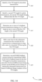
- FIG. 14 shows a flowchart illustrating a method 1400 for asymmetric downlink-uplink TTI configurations for low latency operation in accordance with various aspects of the present disclosure.
- the operations of method 1400 may be implemented by a UE 115 or base station 105 or its components as described herein.
- the operations of method 1400 may be performed by a timing manager as described with reference to FIGs. 8 through 10 .
- a UE 115 or base station 105 may execute a set of codes to control the functional elements of the device to perform the functions described below. Additionally or alternatively, the UE 115 or base station 105 may perform aspects of the functions described below using special-purpose hardware.
- the UE 115 or base station 105 may identify a first TTI length for downlink transmissions.
- the operations of block 1405 may be performed according to the methods described with reference to FIGs. 1 through 7 . In certain examples, aspects of the operations of block 1405 may be performed by a downlink TTI identification component as described with reference to FIGs. 8 through 10 .
- the UE 115 or base station 105 may identify a second TTI length for uplink transmissions, the second TTI length being different than the first TTI length.
- the operations of block 1410 may be performed according to the methods described with reference to FIGs. 1 through 7 . In certain examples, aspects of the operations of block 1410 may be performed by a uplink TTI identification component as described with reference to FIGs. 8 through 10 .
- the UE 115 or base station 105 may determine one or more of a feedback process transmission timing or a TA value based at least in part on one or more of the first TTI length or the second TTI length.
- the operations of block 1415 may be performed according to the methods described with reference to FIGs. 1 through 7 . In certain examples, aspects of the operations of block 1415 may be performed by a timing determination component as described with reference to FIGs. 8 through 10 .
- the UE 115 or base station 105 may shift a start time for the subsequent transmission that includes the new transmission or retransmission to align with a start of a downlink TTI having the first TTI length.
- the operations of block 1420 may be performed according to the methods described with reference to FIGs. 1 through 7 . In certain examples, aspects of the operations of block 1420 may be performed by a timing determination component as described with reference to FIGs. 8 through 10 .
- the UE 115 or base station 105 may determine a second HARQ feedback process timing for transmitting HARQ ACK/NACK feedback based on the first TTI length for downlink transmissions, and where the first HARQ process timing and the second HARQ process timing for starting the subsequent transmission are based on different integer numbers of first TTI lengths.
- the operations of block 1425 may be performed according to the methods described with reference to FIGs. 1 through 7 . In certain examples, aspects of the operations of block 1425 may be performed by a HARQ component as described with reference to FIGs. 8 through 10 .
- FIG. 15 shows a flowchart illustrating a method 1500 for asymmetric downlink-uplink TTI configurations for low latency operation in accordance with various aspects of the present disclosure.
- the operations of method 1500 may be implemented by a UE 115 or base station 105 or its components as described herein.
- the operations of method 1500 may be performed by a timing manager as described with reference to FIGs. 8 through 10 .
- a UE 115 or base station 105 may execute a set of codes to control the functional elements of the device to perform the functions described below. Additionally or alternatively, the UE 115 or base station 105 may perform aspects of the functions described below using special-purpose hardware.
- the UE 115 or base station 105 may identify a first TTI length for downlink transmissions.
- the operations of block 1505 may be performed according to the methods described with reference to FIGs. 1 through 7 . In certain examples, aspects of the operations of block 1505 may be performed by a downlink TTI identification component as described with reference to FIGs. 8 through 10 .
- the UE 115 or base station 105 may identify a second TTI length for uplink transmissions, the second TTI length being different than the first TTI length.
- the operations of block 1510 may be performed according to the methods described with reference to FIGs. 1 through 7 . In certain examples, aspects of the operations of block 1510 may be performed by a uplink TTI identification component as described with reference to FIGs. 8 through 10 .
- the UE 115 or base station 105 may determine one or more of a feedback process transmission timing or a TA value based at least in part on one or more of the first TTI length or the second TTI length.
- the operations of block 1515 may be performed according to the methods described with reference to FIGs. 1 through 7 . In certain examples, aspects of the operations of block 1515 may be performed by a timing determination component as described with reference to FIGs. 8 through 10 .
- the UE 115 or base station 105 may group ACK/NACK feedback for two or more downlink transmissions for transmission in a single subsequent transmission.
- the operations of block 1520 may be performed according to the methods described with reference to FIGs. 1 through 7 . In certain examples, aspects of the operations of block 1520 may be performed by a transmission generation component as described with reference to FIGs. 8 through 10 .
- the UE 115 or base station 105 may transmit the subsequent transmission.
- the operations of block 1525 may be performed according to the methods described with reference to FIGs. 1 through 7 . In certain examples, aspects of the operations of block 1525 may be performed by a transmission generation component as described with reference to FIGs. 8 through 10 , in conjunction with the transmitter.
- FIG. 16 shows a flowchart illustrating a method 1600 for asymmetric downlink-uplink TTI configurations for low latency operation in accordance with various aspects of the present disclosure.
- the operations of method 1600 may be implemented by a UE 115 or base station 105 or its components as described herein.
- the operations of method 1600 may be performed by a timing manager as described with reference to FIGs. 8 through 10 .
- a UE 115 or base station 105 may execute a set of codes to control the functional elements of the device to perform the functions described below. Additionally or alternatively, the UE 115 or base station 105 may perform aspects of the functions described below using special-purpose hardware.
- the UE 115 or base station 105 may identify a first TTI length for downlink transmissions.
- the operations of block 1605 may be performed according to the methods described with reference to FIGs. 1 through 7 . In certain examples, aspects of the operations of block 1605 may be performed by a downlink TTI identification component as described with reference to FIGs. 8 through 10 .
- the UE 115 or base station 105 may identify a second TTI length for uplink transmissions, the second TTI length being different than the first TTI length.
- the operations of block 1610 may be performed according to the methods described with reference to FIGs. 1 through 7 . In certain examples, aspects of the operations of block 1610 may be performed by a uplink TTI identification component as described with reference to FIGs. 8 through 10 .
- the UE 115 or base station 105 may determine one or more of a TBS, a number of spatial layers for the subsequent transmission, a number of CCs to carry the subsequent transmission, or a CQI reporting type for the subsequent transmission.
- the operations of block 1615 may be performed according to the methods described with reference to FIGs. 1 through 7 . In certain examples, aspects of the operations of block 1615 may be performed by a transmission parameter determination component as described with reference to FIGs. 8 through 10 .
- the UE 115 or base station 105 may transmit the subsequent transmission.
- the operations of block 1620 may be performed according to the methods described with reference to FIGs. 1 through 7 . In certain examples, aspects of the operations of block 1620 may be performed by a transmission generation component as described with reference to FIGs. 8 through 10 .
- CDMA code division multiple access
- TDMA time division multiple access
- FDMA frequency division multiple access
- OFDMA orthogonal frequency division multiple access
- SC-FDMA single carrier frequency division multiple access
- a CDMA system may implement a radio technology such as CDMA2000, Universal Terrestrial Radio Access (UTRA), etc.
- CDMA2000 covers IS-2000, IS-95, and IS-856 standards.
- IS-2000 Releases may be commonly referred to as CDMA2000 1X, 1X, etc.
- IS-856 TIA-856) is commonly referred to as CDMA2000 1xEV-DO, High Rate Packet Data (HRPD), etc.
- UTRA includes Wideband CDMA (WCDMA) and other variants of CDMA.
- a TDMA system may implement a radio technology such as Global System for Mobile Communications (GSM).
- GSM Global System for Mobile Communications
- An OFDMA system may implement a radio technology such as Ultra Mobile Broadband (UMB), Evolved UTRA (E-UTRA), Institute of Electrical and Electronics Engineers (IEEE) 802.11 (Wi-Fi), IEEE 802.16 (WiMAX), IEEE 802.20, Flash-OFDM, etc.
- UMB Ultra Mobile Broadband
- E-UTRA Evolved UTRA
- IEEE Institute of Electrical and Electronics Engineers
- Wi-Fi Wi-Fi
- WiMAX IEEE 802.16
- IEEE 802.20 Flash-OFDM
- UMB Ultra Mobile Broadband
- E-UTRA Evolved UTRA
- IEEE 802.11 Wi-Fi
- WiMAX IEEE 802.16
- Flash-OFDM Flash-OFDM
- UTRA and E-UTRA are part of Universal Mobile Telecommunications system (UMTS).
- 3GPP LTE and LTE-A are releases of UMTS that use E-UTRA.
- CDMA2000 and UMB are described in documents from an organization named "3rd Generation Partnership Project 2" (3GPP2).
- 3GPP2 3rd Generation Partnership Project 2
- the techniques described herein may be used for the systems and radio technologies mentioned above as well as other systems and radio technologies. While aspects an LTE or an NR system may be described for purposes of example, and LTE or NR terminology may be used in much of the description, the techniques described herein are applicable beyond LTE or NR applications.
- the term evolved node B may be generally used to describe the base stations.
- the wireless communications system or systems described herein may include a heterogeneous LTE/LTE-A or NR network in which different types of evolved node B (eNBs) provide coverage for various geographical regions.
- eNBs evolved node B
- each eNB, gNB or base station may provide communication coverage for a macro cell, a small cell, or other types of cell.
- the term "cell” may be used to describe a base station, a carrier or component carrier associated with a base station, or a coverage area (e.g., sector, etc.) of a carrier or base station, depending on context.
- Base stations may include or may be referred to by those skilled in the art as a base transceiver station, a radio base station, an access point, a radio transceiver, a NodeB, eNodeB (eNB), next generation NodeB (gNB), Home NodeB, a Home eNodeB, or some other suitable terminology.
- the geographic coverage area for a base station may be divided into sectors making up only a portion of the coverage area.
- the wireless communications system or systems described herein may include base stations of different types (e.g., macro or small cell base stations).
- the UEs described herein may be able to communicate with various types of base stations and network equipment including macro eNBs, small cell eNBs, gNBs, relay base stations, and the like. There may be overlapping geographic coverage areas for different technologies.
- a macro cell generally covers a relatively large geographic area (e.g., several kilometers in radius) and may allow unrestricted access by UEs with service subscriptions with the network provider.
- a small cell is a lower-powered base station, as compared with a macro cell, that may operate in the same or different (e.g., licensed, unlicensed, etc.) frequency bands as macro cells.
- Small cells may include pico cells, femto cells, and micro cells according to various examples.
- a pico cell for example, may cover a small geographic area and may allow unrestricted access by UEs with service subscriptions with the network provider.
- a femto cell may also cover a small geographic area (e.g., a home) and may provide restricted access by UEs having an association with the femto cell (e.g., UEs in a closed subscriber group (CSG), UEs for users in the home, and the like).
- An eNB for a macro cell may be referred to as a macro eNB.
- An eNB for a small cell may be referred to as a small cell eNB, a pico eNB, a femto eNB, or a home eNB.
- An eNB may support one or multiple (e.g., two, three, four, and the like) cells (e.g., component carriers).
- the wireless communications system or systems described herein may support synchronous or asynchronous operation.
- the base stations may have similar frame timing, and transmissions from different base stations may be approximately aligned in time.
- the base stations may have different frame timing, and transmissions from different base stations may not be aligned in time.
- the techniques described herein may be used for either synchronous or asynchronous operations.
- Information and signals described herein may be represented using any of a variety of different technologies and techniques.
- data, instructions, commands, information, signals, bits, symbols, and chips that may be referenced throughout the above description may be represented by voltages, currents, electromagnetic waves, magnetic fields or particles, optical fields or particles, or any combination thereof.
- a general-purpose processor may be a microprocessor, but in the alternative, the processor may be any conventional processor, controller, microcontroller, or state machine.
- a processor may also be implemented as a combination of computing devices (e.g., a combination of a DSP and a microprocessor, multiple microprocessors, one or more microprocessors in conjunction with a DSP core, or any other such configuration).
- the functions described herein may be implemented in hardware, software executed by a processor, firmware, or any combination thereof. If implemented in software executed by a processor, the functions may be stored on or transmitted over as one or more instructions or code on a computer-readable medium. Other examples and implementations are within the scope of the disclosure and appended claims. For example, due to the nature of software, functions described above can be implemented using software executed by a processor, hardware, firmware, hardwiring, or combinations of any of these. Features implementing functions may also be physically located at various positions, including being distributed such that portions of functions are implemented at different physical locations.
- Computer-readable media includes both non-transitory computer storage media and communication media including any medium that facilitates transfer of a computer program from one place to another.
- a non-transitory storage medium may be any available medium that can be accessed by a general purpose or special purpose computer.
- non-transitory computer-readable media may comprise RAM, ROM, electrically erasable programmable read only memory (EEPROM), compact disk (CD) ROM or other optical disk storage, magnetic disk storage or other magnetic storage devices, or any other non-transitory medium that can be used to carry or store desired program code means in the form of instructions or data structures and that can be accessed by a general-purpose or special-purpose computer, or a general-purpose or special-purpose processor.
- RAM random access memory
- ROM read only memory
- EEPROM electrically erasable programmable read only memory
- CD compact disk
- magnetic disk storage or other magnetic storage devices or any other non-transitory medium that can be used to carry or store desired program code means in the form of instructions or data structures
- any connection is properly termed a computer-readable medium.
- the software is transmitted from a website, server, or other remote source using a coaxial cable, fiber optic cable, twisted pair, digital subscriber line (DSL), or wireless technologies such as infrared, radio, and microwave
- the coaxial cable, fiber optic cable, twisted pair, digital subscriber line (DSL), or wireless technologies such as infrared, radio, and microwave are included in the definition of medium.
- Disk and disc include CD, laser disc, optical disc, digital versatile disc (DVD), floppy disk and Blu-ray disc where disks usually reproduce data magnetically, while discs reproduce data optically with lasers. Combinations of the above are also included within the scope of computer-readable media.
Landscapes
- Engineering & Computer Science (AREA)
- Computer Networks & Wireless Communication (AREA)
- Signal Processing (AREA)
- Mobile Radio Communication Systems (AREA)
Description
- The following relates generally to wireless communication, and more specifically to asymmetric downlink-uplink transmission time interval (TTI) configurations for low latency operation.
- Wireless multiple-access technologies have been adopted in various telecommunication standards to provide a common protocol that enables different wireless devices to communicate on a municipal, national, regional, and even global level. An example telecommunication standard is Long Term Evolution (LTE). LTE is designed to improve spectral efficiency, lower costs, improve services, make use of new spectrum, and better integrate with other open standards. LTE may use orthogonal frequency division multiple access (OFDMA) on the downlink, single-carrier frequency division multiple access (SC-FDMA) on the uplink, and multiple-input multiple-output (MIMO) antenna technology.
- In some examples, a wireless multiple-access communication system may include a number of base stations, each simultaneously supporting communication for multiple communication devices, otherwise known as user equipment (UEs). In a LTE or LTE-Advanced (LTE-A) network, a set of one or more base stations may define an eNodeB (eNB). In other examples (e.g., in a next generation new radio (NR) or 5th Generation (5G) network), a wireless multiple access communication system may include a number of smart radio heads (RHs) in communication with a number of access node controllers (ANCs), where a set of one or more RHs, in communication with an ANC, defines a base station (e.g., an eNB or giga-nodeB (gNB)). A base station may communicate with a set of UEs on downlink channels (e.g., for transmissions from a base station to a UE) and uplink channels (e.g., for transmissions from a UE to a base station).
- A base station in some LTE or NR deployments may transmit to one or more UEs using different length TTIs that may be reduced in length relative to legacy LTE TTIs. Such a reduced length TTI may be referred to as a shortened TTI (sTTI) and users communicating using sTTIs may be referred to as low latency users. An sTTI may be a subset of one or more subframes that correspond to legacy TTI subframes. A base station may allocate transmission resources for sTTIs to a UE that may include time resources, frequency resources, and one or more component carriers (CCs) to be used for sTTI transmissions. Efficient allocation of such resources for data, control information, and reference signal transmissions may help to increase the efficiency of a wireless communications system.
- " Views on processing time reduction and related procedures", 3GPP DRAFT, R1-1610049, Lisbon 14 October 2016 discusses process time reduction and related procedures for sTTI.
- " On reduced processing time for short TTI", 3GPP DRAFT, R1-1613394, Reno 19 November 2016 discusses aspects of processing time reduction for short TTI operation in LTE and related aspects.
-
US2016/119948 relates to methods, systems, and devices for wireless communication. A base station may employ a multiplexing configuration based on latency and efficiency considerations. The base station may transmit a resource grant, a signal indicating the length of a downlink (DL) transmission time interval (TTI), and a signal indicating the length of a subsequent uplink (UL) TTI to one or more user equipment (UEs). The base station may dynamically select a new multiplexing configuration by, for example, setting the length of an UL TTI to zero or assigning multiple UEs resources in the same DLTTI. - In accordance with the present invention, there is provided a method for wireless communication as set out in
claim 1, an apparatus for wireless communication as set out inclaim 10 and a computer readable medium storing code for wireless communication as set out inclaim 11. -
-
FIG. 1 illustrates an example of a system for wireless communication that supports asymmetric downlink-uplink transmission time interval (TTI) configurations for low latency operation in accordance with aspects of the present disclosure. -
FIG. 2 illustrates an example of a system for wireless communication that supports asymmetric downlink-uplink TTI configurations for low latency operation in accordance with aspects of the present disclosure. -
FIG. 3 illustrates an example of asymmetric uplink and downlink TTIs and associated timings for low latency operation in accordance with aspects of the present disclosure. -
FIG. 4 illustrates an example of symmetric uplink and downlink TTIs and associated timings for low latency operation in accordance with aspects of the present disclosure. -
FIG. 5 illustrates an example of feedback reception to transmission or retransmission timing for asymmetric uplink and downlink TTIs in accordance with aspects of the present disclosure. -
FIG. 6 illustrates an example of feedback bundling across subframe boundaries that supports asymmetric downlink-uplink TTI configurations for low latency operation in accordance with aspects of the present disclosure. -
FIG. 7 illustrates an example of a process flow that supports asymmetric downlink-uplink TTI configurations for low latency operation in accordance with aspects of the present disclosure. -
FIGs. 8 through 10 show block diagrams of a device that supports asymmetric downlink-uplink TTI configurations for low latency operation in accordance with aspects of the present disclosure. -
FIG. 11 illustrates a block diagram of a system including a user equipment (UE) that supports asymmetric downlink-uplink TTI configurations for low latency operation in accordance with aspects of the present disclosure. -
FIG. 12 illustrates a block diagram of a system including a base station that supports asymmetric downlink-uplink TTI configurations for low latency operation in accordance with aspects of the present disclosure. -
FIGs. 13 through 16 illustrate methods for asymmetric downlink-uplink TTI configurations for low latency operation in accordance with aspects of the present disclosure. - The described techniques relate to improved methods, systems, devices, or apparatuses that support wireless transmissions in systems that may have asymmetric transmission time intervals (TTIs) for uplink and downlink transmissions. Some transmissions may use shortened TTIs (sTTIs) for uplink or downlink transmissions, in which a length of the sTTI may be shorter than a legacy Long Term Evolution (LTE) TTI or a 1 ms TTI, and in which uplink transmissions and downlink transmissions may use different length TTIs or sTTIs. Resources allocated for sTTI transmissions may be used for uplink and/or downlink communications that are relatively latency sensitive, referred to as low latency communications, relative to communications that may be relatively latency insensitive, such as enhanced mobile broadband (eMBB) transmissions that may use a 1 ms (or legacy LTE) TTI duration. In some cases, an sTTI duration may correspond to one slot of a wireless subframe, or to two or three orthogonal frequency division multiplexing (OFDM) symbols, for example, and a 1 ms TTI duration may correspond to a duration of a 1 ms subframe.
- Such low latency communications may be used in systems, for example, that may support multiple different services for data communications. Such different services may be selected depending upon the nature of the communications. For example, communications that require low latency and high reliability, sometimes referred to as mission critical communications, may be served through a lower-latency service (e.g., an ultra-reliable low-latency communication (URLLC) service) that uses sTTIs. Correspondingly, communications that are more delay-tolerant may be served through a service that provides relatively higher throughput with somewhat higher latency, such as a mobile broadband service (e.g., an eMBB service) that uses 1 ms TTIs. In other examples, communications may be with UEs that are incorporated into other devices (e.g., meters, vehicles, appliances, machinery, etc.), and a machine-type communication (MTC) service (e.g., massive MTC (mMTC)) may be used for such communications. In some cases, different services (e.g., eMBB, URLLC, mMTC) may have different TTIs, different sub-carrier (or tone) spacing and different cyclic prefixes.
- The present disclosure describes various techniques with reference to next generation networks (e.g., 5th Generation (5G) or new radio (NR) networks) that are being designed to support features such as high bandwidth operations, more dynamic subframe/slot types, and self-contained subframe/slot types (in which hybrid automatic repeat request (HARQ) feedback for a subframe/slot may be transmitted before the end of the subframe/slot). However, such techniques may be used for any system in which TTIs of different lengths may be transmitted in a wireless communications system.
- The described techniques provided in various examples provide for identifying an uplink TTI length for uplink transmissions, and a downlink TTI length for downlink transmissions, in which the uplink TTI length and the downlink TTI length may be different and one or both of the uplink and downlink TTIs may be sTTIs. For example, the downlink TTI length may be sTTI length, and the uplink TTI length may be longer than the downlink sTTI length (e.g., a longer sTTI or a 1 ms TTI). Various parameters for transmissions between a user equipment (UE) and a base station may be determined based on one or more of the uplink TTI length or the downlink TTI length. For example, one or more of a feedback process (e.g., a HARQ process) transmission timing, a timing advance (TA) value, a transport block size (TBS), a number of spatial layers, a number of component carriers (CCs), or a channel quality information (CQI) reporting type for uplink and/or downlink transmissions may be determined based on one or more of the uplink TTI length or the downlink TTI length.
- In some examples, a downlink HARQ timing may be based on the downlink TTI length, and a timing between receipt of HARQ feedback and responsive transmissions or retransmissions of data may be based on the uplink TTI length. In other examples, the downlink HARQ timing may be based on the downlink TTI length, and the timing between receipt of HARQ feedback and responsive transmissions or retransmissions of data may also be based on the downlink TTI length. In some cases, a timing for transmission of HARQ feedback or timing of the responsive transmissions or retransmissions may be shifted to provide that the transmission aligns with a TTI or sTTI boundary. In some cases, the downlink sTTI length may be shorter than the uplink sTTI or TTI length, and HARQ feedback information may be grouped and transmitted according to the downlink HARQ timing.
- In some examples, a TA value may be determined based on the downlink TTI length, and a maximum TA value may be identified. Other parameters, such as a TBS, number of spatial layers, number of CCs, or CQI reporting type may be identified based at least in part on the TA value or maximum TA value. In some cases, an uplink control channel transmission may include HARQ feedback for two or more downlink sTTIs, and coding (e.g., Reed-Muller coding or Turbo coding) may be used to code HARQ feedback. In some cases, the TA value may be determined based on the uplink sTTI or TTI length, and processing timing (e.g., HARQ feedback transmission timing) may be based on the uplink sTTI or TTI length.
- Aspects of the disclosure are initially described in the context of a wireless communications system. Various asymmetric TTI lengths with associated timings and transmissions are then described. Aspects of the disclosure are further illustrated by and described with reference to apparatus diagrams, system diagrams, and flowcharts that relate to asymmetric downlink-uplink transmission time interval configurations for low latency operation.
-
FIG. 1 illustrates an example of awireless communications system 100 in accordance with various aspects of the present disclosure. Thewireless communications system 100 includesbase stations 105, UEs 115, and acore network 130. In some examples, thewireless communications system 100 may be an LTE, LTE-Advanced (LTE-A) network, or an NR network. In some cases,wireless communications system 100 may support enhanced broadband communications, ultra-reliable (e.g., mission critical) communications, low latency communications, and communications with low-cost and low-complexity devices.Wireless communications system 100 may provide for wireless transmissions in which uplink TTIs and downlink TTIs may be asymmetric, with various transmissions and timings based on one or both of the uplink or downlink TTI length. -
Base stations 105 may wirelessly communicate withUEs 115 via one or more base station antennas. Eachbase station 105 may provide communication coverage for a respectivegeographic coverage area 110.Communication links 125 shown inwireless communications system 100 may include uplink transmissions from aUE 115 to abase station 105, or downlink transmissions, from abase station 105 to aUE 115. Control information and data may be multiplexed on an uplink channel or downlink according to various techniques. Control information and data may be multiplexed on a downlink channel, for example, using time division multiplexing (TDM) techniques, frequency division multiplexing (FDM) techniques, or hybrid TDM-FDM techniques. In some examples, the control information transmitted during a TTI of a downlink channel may be distributed between different control regions in a cascaded manner (e.g., between a common control region and one or more UE-specific control regions). -
UEs 115 may be dispersed throughout thewireless communications system 100, and eachUE 115 may be stationary or mobile. AUE 115 may also be referred to as a mobile station, a subscriber station, a mobile unit, a subscriber unit, a wireless unit, a remote unit, a mobile device, a wireless device, a wireless communications device, a remote device, a mobile subscriber station, an access terminal, a mobile terminal, a wireless terminal, a remote terminal, a handset, a user agent, a mobile client, a client, or some other suitable terminology. AUE 115 may also be a cellular phone, a personal digital assistant (PDA), a wireless modem, a wireless communication device, a handheld device, a tablet computer, a laptop computer, a cordless phone, a personal electronic device, a handheld device, a personal computer, a wireless local loop (WLL) station, an Internet of things (IoT) device, an Internet of Everything (IoE) device, an MTC device, an appliance, an automobile, or the like. - In some cases, a
UE 115 may also be able to communicate directly with other UEs (e.g., using a peer-to-peer (P2P) or device-to-device (D2D) protocol). One or more of a group ofUEs 115 utilizing D2D communications may be within thecoverage area 110 of a cell.Other UEs 115 in such a group may be outside thecoverage area 110 of a cell, or otherwise unable to receive transmissions from abase station 105. In some cases, groups ofUEs 115 communicating via D2D communications may utilize a one-to-many (1:M) system in which eachUE 115 transmits to everyother UE 115 in the group. In some cases, abase station 105 facilitates the scheduling of resources for D2D communications. In other cases, D2D communications are carried out independent of abase station 105. - Some
UEs 115, such as MTC or IoT devices, may be low cost or low complexity devices, and may provide for automated communication between machines, i.e., Machine-to-Machine (M2M) communication. M2M or MTC may refer to data communication technologies that allow devices to communicate with one another or a base station without human intervention. For example, M2M or MTC may refer to communications from devices that integrate sensors or meters to measure or capture information and relay that information to a central server or application program that can make use of the information or present the information to humans interacting with the program or application. SomeUEs 115 may be designed to collect information or enable automated behavior of machines. Examples of applications for MTC devices include smart metering, inventory monitoring, water level monitoring, equipment monitoring, healthcare monitoring, wildlife monitoring, weather and geological event monitoring, fleet management and tracking, remote security sensing, physical access control, and transaction-based business charging. - In some cases, an MTC device may operate using half-duplex (one-way) communications at a reduced peak rate. MTC devices may also be configured to enter a power saving "deep sleep" mode when not engaging in active communications. In some cases, MTC or IoT devices may be designed to support mission critical functions and wireless communications system may be configured to provide ultra-reliable communications for these functions.
-
Base stations 105 may communicate with thecore network 130 and with one another. For example,base stations 105 may interface with thecore network 130 through backhaul links 132 (e.g., S1, etc.).Base stations 105 may communicate with one another over backhaul links 134 (e.g., X2, etc.) either directly or indirectly (e.g., through core network 130).Base stations 105 may perform radio configuration and scheduling for communication withUEs 115, or may operate under the control of a base station controller (not shown). In some examples,base stations 105 may be macro cells, small cells, hot spots, or the like.Base stations 105 may also be referred to as eNodeBs (eNBs) 105. - A
base station 105 may be connected by an S1 interface to thecore network 130. The core network may be an evolved packet core (EPC), which may include at least one mobility management entity (MME), at least one serving gateway (S-GW), and at least one packet data network (PDN) gateway (P-GW). The MME may be the control node that processes the signaling between theUE 115 and the EPC. All user Internet Protocol (IP) packets may be transferred through the S-GW, which itself may be connected to the P-GW. The P-GW may provide IP address allocation as well as other functions. The P-GW may be connected to the network operators IP services. The operators IP services may include the Internet, the Intranet, an IP Multimedia Subsystem (IMS), and a Packet-Switched (PS) Streaming Service (PSS). - The
core network 130 may provide user authentication, access authorization, tracking, IP connectivity, and other access, routing, or mobility functions. At least some of the network devices, such as abase station 105 may include subcomponents such as an access network entity, which may be an example of an access node controller (ANC). Each access network entity may communicate with a number ofUEs 115 through one or more access network transmission entities, each of which may be an example of a smart radio head, or a transmission reception point (TRP). In some configurations, various functions of each access network entity orbase station 105 may be distributed across various network devices (e.g., radio heads and access network controllers) or consolidated into a single network device (e.g., a base station 105). -
Wireless communications system 100 may operate in an ultra high frequency (UHF) frequency region using frequency bands from 700 MHz to 2600 MHz (2.6 GHz), although in some cases, a wireless local area network (WLAN) may use frequencies as high as 4 GHz. This region may also be known as the decimeter band, since the wavelengths range from approximately one decimeter to one meter in length. UHF waves may propagate mainly by line of sight, and may be blocked by buildings and environmental features. However, the waves may penetrate walls sufficiently to provide service to UEs 115 located indoors. Transmission of UHF waves is characterized by smaller antennas and shorter range (e.g., less than 100 km) compared to transmission using the smaller frequencies (and longer waves) of the high frequency (HF) or very high frequency (VHF) portion of the spectrum. In some cases,wireless communications system 100 may also utilize extremely high frequency (EHF) portions of the spectrum (e.g., from 30 GHz to 300 GHz). This region may also be known as the millimeter band, since the wavelengths range from approximately one millimeter to one centimeter in length. Thus, EHF antennas may be even smaller and more closely spaced than UHF antennas. In some cases, this may facilitate use of antenna arrays within a UE 115 (e.g., for directional beamforming). - In some cases,
wireless communications system 100 may be a packet-based network that operate according to a layered protocol stack. In the user plane, communications at the bearer or packet data convergence protocol (PDCP) layer may be IP-based. A radio link control (RLC) layer may in some cases perform packet segmentation and reassembly to communicate over logical channels. A Medium Access Control (MAC) layer may perform priority handling and multiplexing of logical channels into transport channels. The MAC layer may also use HARQ to provide retransmission at the MAC layer to improve link efficiency. In the control plane, the radio resource control (RRC) protocol layer may provide establishment, configuration, and maintenance of an RRC connection between aUE 115 and a network device such as abase station 105 orcore network 130 supporting radio bearers for user plane data. At the Physical (PHY) layer, transport channels may be mapped to physical channels. - Time intervals in LTE or NR may be expressed in multiples of a basic time unit (which may be a sampling period of Ts = 1/30,720,000 seconds). Time resources may be organized according to radio frames of length of 10ms (Tf= 307200Ts), which may be identified by a system frame number (SFN) ranging from 0 to 1023. Each frame may include ten 1 ms subframes numbered from 0 to 9. A subframe may be further divided into two .5ms slots, each of which contains 6 or 7 modulation symbol periods (depending on the length of the cyclic prefix prepended to each symbol). Excluding the cyclic prefix, each symbol contains 2048 sample periods. In some cases the subframe may be the smallest scheduling unit, also known as a TTI. In other cases, a TTI may be shorter than a subframe or may be dynamically selected (e.g., in short TTI bursts or in selected component carriers using short TTIs).
- A resource element may consist of one symbol period and one subcarrier (e.g., a 15 kHz frequency range). A resource block may contain 12 consecutive subcarriers in the frequency domain and, for a normal cyclic prefix in each OFDM symbol, 7 consecutive OFDM symbols in the time domain (1 slot), or 84 resource elements. The number of bits carried by each resource element may depend on the modulation scheme (the configuration of symbols that may be selected during each symbol period, which may be referred to as a modulation and coding scheme (MCS)). Thus, the more resource blocks that a UE receives and the higher the modulation scheme, the higher the data rate may be.
-
Wireless communications system 100 may support operation on multiple cells or carriers, a feature which may be referred to as carrier aggregation (CA) or multi-carrier operation. A carrier may also be referred to as a CC, a layer, a channel, etc. The terms "carrier," "component carrier," "cell," and "channel" may be used interchangeably herein. AUE 115 may be configured with multiple downlink CCs and one or more uplink CCs for carrier aggregation. Carrier aggregation may be used with both frequency division duplexing (FDD) and time division duplexing (TDD) component carriers. - In some cases,
wireless communications system 100 may utilize enhanced component carriers (eCCs). An eCC may be characterized by one or more features including: wider bandwidth, shorter symbol duration, shorter TTIs, and modified control channel configuration. In some cases, an eCC may be associated with a carrier aggregation configuration or a dual connectivity configuration (e.g., when multiple serving cells have a suboptimal or non-ideal backhaul link). An eCC may also be configured for use in unlicensed spectrum or shared spectrum (where more than one operator is allowed to use the spectrum). An eCC characterized by wide bandwidth may include one or more segments that may be utilized byUEs 115 that are not capable of monitoring the whole bandwidth or prefer to use a limited bandwidth (e.g., to conserve power). In some cases, an eCC may utilize a different symbol duration than other CCs, which may include use of a reduced symbol duration as compared with symbol durations of the other CCs. A shorter symbol duration may be associated with increased subcarrier spacing. A TTI in an eCC may consist of one or multiple symbols. In some cases, the TTI duration (that is, the number of symbols in a TTI) may be variable. - In some cases,
wireless communications system 100 may utilize both licensed and unlicensed radio frequency spectrum bands. For example,wireless communications system 100 may employ LTE License Assisted Access (LTE-LAA) or LTE Unlicensed (LTE U) radio access technology or NR technology in an unlicensed band such as the 5 GHz Industrial, Scientific, and Medical (ISM) band. When operating in unlicensed radio frequency spectrum bands, wireless devices such asbase stations 105 andUEs 115 may employ listen-before-talk (LBT) procedures to ensure the channel is clear before transmitting data. In some cases, operations in unlicensed bands may be based on a CA configuration in conjunction with CCs operating in a licensed band. Operations in unlicensed spectrum may include downlink transmissions, uplink transmissions, or both. Duplexing in unlicensed spectrum may be based on FDD, TDD, or a combination of both. - As indicated above, in some cases,
base stations 105 andUEs 115 may use a HARQ process to provide feedback (e.g., acknowledgment/negative-acknowledgment (ACK/NACK) feedback) of successful receipt of transmissions and to provide retransmissions in the event that a transmission is not successfully received. Timings for generating and transmitting HARQ feedback and for generating and retransmitting unsuccessfully received transmissions may be based on pre-established rules for such timing between a reception TTI and a subsequent transmission. For example, an n+4 rule may be established in which the subsequent transmission is to be made four TTIs, or a first available TTI thereafter, following the reception TTI. In such cases, if a reception TTI is TTI-0, the subsequent transmission would be made at TTI-4. In cases, where asymmetric TTI lengths are used for uplink and downlink transmissions, various aspects of the present disclosure provide for techniques for determining timing and/or other parameters to account for the different TTI lengths for uplink and downlink transmissions. Such timing techniques may also be used for other timings as well, such as for timing between reception of downlink control information (DCI) and an associated uplink transmission, for example. - Further, when transmitting uplink transmissions, a
UE 115 may use a TA value that may compensate for propagation delay between when theUE 115 starts a transmission and when abase station 105 receives the transmission. The TA value is a negative offset, at theUE 115, between the start of a received downlink TTI and a transmitted uplink TTI. This offset at theUE 115 may help to ensure that the downlink and uplink TTI transmissions are synchronized at thebase station 105. AUE 115 that is located relatively far from a servingbase station 105 may encounter a larger propagation delay, so its uplink transmission is started earlier than anotherUE 115 that is closer to the sameserving base station 105. In some examples, maximum TA threshold values may be set to provide aUE 115 with sufficient processing time prior to the start of an uplink transmission. In some cases, a TA value and maximum TA threshold value may be determined based in a TTI length of uplink or downlink transmissions, and one or more other parameters, such as a TBS, number of spatial layers, number of CCs, or CQI reporting type may be identified based at least in part on the TA value. -
FIG. 2 illustrates an example of awireless communications system 200 for asymmetric downlink-uplink TTI configurations for low latency operation in accordance with various aspects of the present disclosure.Wireless communications system 200 includes base station 105-a and UE 115-a, which may be examples of aspects of aUE 115 as described above with reference toFIG. 1 . In the example ofFIG. 2 , thewireless communications system 200 may operate according to a radio access technology (RAT) such as a 5G or NR RAT, although techniques described herein may be applied to any RAT and to systems that may concurrently use two or more different RATs. - Base station 105-a may communicate with UE 115-a over an
uplink carrier 205 and adownlink carrier 215. In some examples, base station 105-a may allocate resources for communication withUEs 115 overuplink carrier 205 anddownlink carrier 215. For example, base station 105-a may allocateuplink subframes 210 inuplink carrier 205 for uplink transmissions from UE 115-a, and one ormore uplink subframes 210 may correspond to a legacy LTE TTI of 1 ms. In this example,uplink subframes 210 may include a first uplink subframe 210-a, a second uplink subframe 210-b, and a third uplink subframe 210-c. Each of theuplink subframes 210 may include two slots, in which each slot may have seven OFDM symbols for a normal cyclic prefix. In this example, a first slot (slot 0) 225 and a second slot (slot 1) 230 may be included in the first uplink subframe 210-a. - As indicated above, in the uplink of a low latency system, different sTTI lengths may be used for transmissions over
uplink carrier 205. For example, two-symbol sTTI and 1-slot sTTI durations may be supported for physical uplink control channel (PUCCH) and physical uplink shared channel (PUSCH) transmissions (or shortened PUCCH (sPUCCH) and shortened PUSCH (sPUSCH) transmissions). Thus, withinfirst slot 225 orsecond slot 230, there may be multiple sTTIs, such as a first sTTI (TTI-0) 235, a second sTTI (TTI-1) 240, and a third sTTI (TTI-2) 245, that may each have a two or three OFDM symbol duration. Such TTI durations may also apply to downlinksubframes 220 transmitted ondownlink carrier 215. In some examples, different length TTIs may be used on theuplink carrier 205 and thedownlink carrier 215, resulting in asymmetric TTI lengths for uplink and downlink transmissions. - When a two-symbol sTTI is used, in some cases it may be desirable to have a fixed sTTI structure in which sTTI boundaries lie within slot boundaries or are aligned with slot boundaries, such as the boundaries of the
first slot 225 orsecond slot 230, which may be referred to as slot-aligned sTTIs. As discussed above, when using a normal cyclic prefix, seven symbols are included in each of first slot andsecond slot 230, and thus each slot may include three sTTIs for slot-aligned sTTIs. In some cases, one of the sTTIs may be configured as a three-symbol TTI, so as to efficiently utilize each symbol of each slot. In such cases, different patterns can be considered, such as having the three-symbol TTI located at the end offirst slot 225 orsecond slot 230, or at the beginning offirst slot 225 orsecond slot 230. When using two-symbol sTTIs or a combination of two-symbol and three-symbol sTTIs, such sTTIs may be referred to as 2-symbol sTTIs. When using sTTIs having a duration corresponding to one slot, such sTTIs may be referred to as slot sTTIs. When using TTIs having a duration correspond to a subframe, such TTIs may be referred to as 1 ms TTIs or legacy TTIs. - In some cases, although UE 115-a may be served using a 2-symbol sTTI in downlink transmissions, a 2-symbol uplink transmission (such as PUCCH or sPUCCH) may not provide sufficient uplink coverage to provide reliable reception of the uplink transmissions. In such cases, a longer sTTI (e.g., a slot sPUCCH) or a 1 ms PUCCH, may be employed for uplink transmissions. The possibility of increasing the uplink coverage comes at the cost of increasing the HARQ round trip time (RTT) due to the asymmetry in the downlink and uplink TTI lengths. In such cases, the UE 115-a may be scheduled for a 2-symbol sTTI in a downlink transmission and may be configured to use either a 1-slot sPUCCH or a 1 ms PUCCH depending on its channel condition. In either case, the associated sPUCCH or PUCCH transmission may provide uplink information for multiple 2-symbol downlink sTTIs. In some examples, 2-symbol downlink sTTIs may use a first pattern of symbols {3,2,2,2,2,3} for the two slots within a subframe boundary, or may use a second pattern of symbols {2,3,2,2,2,3} for such transmissions. In some cases, the pattern to be used may be indicated in a physical control format indicator channel (PCFICH), in which a PCFICH value of 1 or 3 indicated the first pattern, and a PCFICH value of 2 indicates the second pattern. One of the following two patterns will also be specified for the uplink transmissions for 2-symbol sTTI transmissions: {3,2,2,2,2,3} or {2,2,3,2,2,3}. As indicated above, in some cases asymmetric uplink and downlink TTIs may be used, and this the timing for various transmissions may be determined based on one or more of the uplink TTI or downlink TTI.
-
FIG. 3 illustrates an example of asymmetric uplink and downlinkTTIs 300 and associated timings for low latency operation, in accordance with various aspects of the disclosure. Asymmetric uplink and downlinkTTIs 300 may be used for communications between a UE and a base station such as discussed above with respect toFIGs. 1 and2 . In this example, downlinksTTIs 305 may be used for downlink transmissions from a base station to a UE, and be transmitted using the pattern {3,2,2,2,2,3} as discussed above. In this example, sTTI-0 315 may be a three-symbol sTTI, sTTI-1 320 through sTTI-4 335 may be two-symbol sTTIs, and sTTI-5 340 and sTTI-6 345 may be three-symbol sTTIs in accordance with the downlink pattern. - Also in this example, uplink
sTTIs 310 may be used for uplink transmissions from the UE to the base station, and may have a longer TTI duration thandownlink sTTIs 305. In this example, each of theuplink sTTIs 310 may be slot sTTIs, having a length that corresponds to a slot of a subframe. As discussed above, assuming a normal cyclic prefix, eachslot sTTI 350 through 365 may have a duration that corresponds to seven OFDM symbols, and downlink sTTIs 305 and uplinksTTIs 310 may be slot-aligned. Such a configuration of asymmetric uplink and downlink TTIs may be referred to as a {2,7} configuration, with a 2-symbol sTTI for downlink transmissions and a slot sTTI (7 symbols) for uplink transmissions. Other configurations may be referred to using such a nomenclature, with {2,2} referring to 2-symbol sTTIs for both uplink and downlink, {2,14} referring to 2-symbol downlink and 1 ms uplink TTIs, and {7,14} referring to slot sTTI downlink and 1 ms uplink TTIs. - As discussed above, for HARQ ACK/NACK feedback, the ACK/NACK transmission may be transmitted during a TTI that with the relationship n+4 following the TTI in which a transmission is received. That is, for a downlink reception in TTI n, ACK/NACK feedback is to be transmitted at or after TTI n+4. However, when using asymmetric uplink and downlink TTIs, in which the
uplink TTIs 310 are longer than thedownlink sTTIs 305 such as inFIG. 3 , ACK/NACK feedback information frommultiple downlink sTTIs 305 may be reported in oneuplink sTTI 310. In this example, the TTI length associated withdownlink sTTIs 305 may be used to determine anuplink sTTI 310 that is to be used for transmitting ACK/NACK feedback, and ACK/NACK feedback for eachdownlink sTTI 305 in a slot may be reported in anuplink sTTI 310. Given the n+4 timing of this example, the sTTI associated with the last downlink transmission is used as TTI n, which corresponds to sTTI-2 325 in this example. Using a 2-symbol sTTI as the sTTI length, the value of n+4 would result in a start time for the subsequent ACK/NACK transmission beginning at the last symbol ofslot1 355, and with the sTTI associated with n+4 spanning to the first symbol ofslot2 360. In such cases, the start time of the subsequent transmission may be shifted to start at the beginning ofslot2 360, and the ACK/NACK feedback for sTTI-0 315 through sTTI-2 may be reported in sPUCCH transmissions that are transmitted in the uplink sTTI corresponding toslot2 360. Similarly, the ACK/NACK feedback fordownlink sTTIs 305 corresponding to slot1 355 may be transmitted inslot3 365. - A UE groups ACK/NACK feedback across subframe boundaries and transmit the grouped feedback information according to a transmission timing associated with the sTTIs in the earlier subframe. For example, sTTIs within slot-2 360 (of subframe N) may be grouped with sTTIs within slot-1 355 (of subframe N-1) and HARQ ACK/NACK feedback may be transmitted to the base station in slot 0 (subframe N+1). Such grouping in this configuration provides a sufficient symbol gap for processing both at the UE and at the base station. Based on the n + 4 timing rule when n is the 2-symbol sTTI duration, this gap may be sufficient. In another example, for n+6 timeline (e.g., k = 6), the HARQ ACK/NAK of sTTI-4 and sTTI-5 of subframe N - 1 and sTTI-0 of subframe N will be mapped to uplink
slot 0 of subframe N + 1. - Techniques may also be applicable and utilized for processing between an uplink grant (e.g., received via a downlink sTTI 305) and a uplink transmission (e.g., for transmission via an sPUSCH in an uplink sTTI 310). For example, an uplink grant for
slot 0 insubframe 4 may be sent in sTTI-4 ofsubframe 1, sTTI-5 ofsubframe 1, or sTTI-0 ofsubframe 2. An uplink grant forslot 1 insubframe 4 may be transmitted in sTTI-1, sTTI-2, or sTTI-3 ofsubframe 2. In such cases, this may allow sufficient time for processing the uplink grant received in adownlink sTTI 305 before transmitting in anuplink sTTI 310. -
FIG. 4 illustrates an example of symmetric uplink and downlinkTTIs 400 with grouping for low latency operation in accordance with various aspects of the present disclosure. Symmetric uplink and downlinkTTIs 400 may be used for communications between a UE and a base station such as discussed above with respect toFIGs. 1 and2 . In this example, downlinksTTIs 405 may be used for downlink transmissions from a base station to a UE, and be transmitted using the pattern {3,2,2,2,2,3} as discussed above.Uplink sTTIs 410 may be used for uplink transmissions from a UE to a base station, and be transmitted using the pattern {3,2,2,2,2,3} as discussed above. In this example, downlinksTTIs 405 may include a three-symbol sTTI-0 415, sTTI-1 420 through sTTI-4 435 may be two-symbol sTTIs, and sTTI-5 440 and sTTI-6 445 may be three-symbol sTTIs in accordance with the downlink pattern. Theuplink sTTIs 410 may have a same {3,2,2,2,2,3} pattern, although the techniques as described herein are applicable in cases where theuplink sTTIs 410 have a different pattern than thedownlink sTTIs 405. - Such a configuration of uplink and downlink TTIs may be referred to as a {2,2} configuration, with a 2-symbol sTTI for downlink and uplink transmissions. As discussed above, for HARQ ACK/NACK feedback, the ACK/NACK transmission may be transmitted during a TTI that with the relationship n+4 following the TTI in which a transmission is received. In this case, for a downlink reception in TTI n, which corresponds to sTTI-0 415 in this example, ACK/NACK feedback is to be transmitted at or after TTI n+4, which corresponds to uplink sTTI- 4 450. ACK/NACK feedback for downlink sTTI-1 420 may be transmitted in uplink sTTI-5 455, and ACK/NACK feedback for downlink sTTI-2 425 may be transmitted in uplink sTTI-6 460. However, as the uplink sTTI-6 460 is a three-symbol sTTI, the subsequent ACK/NACK transmission for downlink sTTI-3 430 would start in the last symbol of uplink sTTI-6 460, and thus the transmission of the ACK/NACK transmission for downlink sTTI-3 430 may be time shifted to align with uplink sTTI-7 465. Similarly, because of the two consecutive uplink three-symbol sTTIs sTTI-5 455 and sTTI-6 460, the ACK/NACK transmission for downlink sTTI-4 435 may align with uplink sTTI-7 465. Finally, in this example, ACK/NACK feedback for downlink sTTI-5 440 may be transmitted in uplink sTTI-9 475, with uplink sTTI-8 470 not carrying any HARQ ACK/NACK feedback information. In some cases, when ACK/NACK feedback for
multiple downlink sTTIs 405 are included in asingle uplink sTTI 410, the combined ACK/NACK feedback may be coded, such as according to a Turbo coding scheme or a RM coding scheme, for example. - Thus, overall HARQ feedback timing may be reduced when using shorter uplink sTTIs. For example, under the n+4 timing rule, the average downlink HARQ delay is 6.66 symbols if a {2,2} configuration is assumed, and 9.33 symbols if a {2,7} configuration is assumed. Thus, the price of using a longer sTTI length in the uplink is increasing the downlink HARQ timing by about 190 microseconds (µs), and thus increasing the overall RTT and latency relative to the {2,2} configuration. As indicated above, in some cases an increased uplink TTI length may be selected based on channel conditions. As channel conditions worsen, the likelihood for HARQ retransmissions increases, which may also impact latency in the system. Thus, in some examples, the TTI length for uplink transmissions may be selected based at least in part on channel conditions, in which a longer uplink TTI may be selected when the associated increase in HARQ timing provides an overall benefit when taking into account an expected rate of retransmissions for relatively poor channel conditions. In some cases, a base station may receive CQI information from a UE and may configure the UE for particular TTI durations based at least in part on the CQI.
-
FIG. 5 illustrates an example of feedback reception to transmission orretransmission timing 500 for asymmetric downlink-uplink TTI configurations for low latency operation in accordance with various aspects of the present disclosure. Uplink and downlinktransmission time intervals 500 may be used for communications between a UE and a base station such as discussed above with respect toFIGs. 1 and2 . In this example, downlinksTTIs 505 may be used for downlink transmissions for a UE to a base station, and may include 1 ms TTIs, 2-symbol sTTIs or slot sTTIs. In this example,downlink slot n 515 through downlink slot n+4 are illustrated, along withuplink slot n 540 through uplink slot n+4 560. In this example, uplinksTTIs 510 may be slot sTTIs, and HARQ ACK/NACK feedback may be received by a base station from a UE duringuplink slot n 565. - The base station may process the AKC/NACK feedback and determine if a previous transmission is to be retransmitted, or if a new transmission may be transmitted, responsive to the ACK/NACK feedback. If the
downlink sTTIs 505 have a length of a slot sTTI or 1 ms TTI, then the ACK/NAK to transmission/retransmission timing could be based on the n+4 rule, as indicated atarrow 565 is this example. In other cases, thedownlink sTTIs 505 may be 2-symbol sTTIs, and the base station may prepare a new transmission or a retransmission more quickly than is thedownlink sTTIs 505 were longer. This is due to the TBS being inversely proportional to the TTI length, although certain processing operations may not be performed faster at the base station for shorter TTIs, such as, channel estimation and sPUCCH decoding, for example. Thus, the ACK/NAK to transmission/retransmission timing may be computed as a function of the uplink sTTI length, but under shortened processing time, e.g., n+3 or n+2 as shown in the figure atarrow 570 andarrow 575, respectively. - In various examples, the processing timing at the base station may be based on the downlink TTI length or the uplink TTI length. In examples where the processing timing is based on the uplink TTI length (e.g., 1 slot or 1 ms), the timing could be n + 2, n + 3 or n + 4, where n is the duration of the uplink TTI. If the downlink sTTI length is 2 symbols, then the timing choice may be n + Z where n is the duration of the uplink TTI. In such examples, in a {2,7} configuration, if the base station processing is based on n + 2 and slot duration, there will be 7 symbol gap between the ACK/NACK feedback reception and transmission/retransmission. In a {2,14} configuration, if the base station processing is based on n + 2 and 1 ms duration, there will be a 14 symbol gap between the ACK/NACK feedback reception and transmission/retransmission.
- In other examples, processing timing at the base station may be based on the downlink TTI length, and n + k timing may be used (e.g., where k ≥ 4 and n is the 2-symbol sTTI length), and thus the processing timing is based on the downlink sTTI length. In some cases, the transmission/retransmission is not necessarily aligned with either the slot or subframe boundaries, and may be initiated based on the n + k timing. As an example, if the 7-symbol or the 14-symbol gap discussed above are not sufficient, or if more flexibility is desired in terms of the retransmission timings, this option may be selected.
-
FIG. 6 illustrates an example of feedback bundling acrosssubframe boundaries 600 for asymmetric downlink-uplink TTI configurations for low latency operation in accordance with various aspects of the present disclosure. Feedback bundling acrosssubframe boundaries 600 may be used for communications between a UE and a base station such as discussed above with respect toFIGs. 1 and2 . In this example, downlinksTTIs 605 may be slot-aligned sTTIs used for downlink transmissions for a UE to a base station, and may include 2-symbol sTTIs. In this example, downlink subframe boundaries are illustrated for downlink subframe-0 615 through downlink subframe-4 635, along with uplink subframe-0 640 through uplink subframe-4 660. In this example, uplinkTTIs 610 may be 1 ms TTIs. - In this example, a UE groups ACK/NACK feedback across subframe boundaries and transmit the grouped feedback information according to a transmission timing associated with the sTTIs in the earlier subframe. For example, sTTIs within slot-1 665 of subframe-0 615 may be grouped with sTTIs within slot-0 670 of subframe-1 620 to generate feedback for a
time period 675 that spans a subframe boundary, and HARQ ACK/NACK feedback 680 may be transmitted to the base station in uplink subframe-2 650. Such grouping in this configuration provides a 7-symbol gap for processing both at the UE and at the base station. Based on the n + 4 timing rule when n is the 2-symbol sTTI duration, this gap may be sufficient. - The base station may process the ACK/NACK feedback and determine if a previous transmission is to be retransmitted, or if a new transmission may be transmitted, responsive to the ACK/NACK feedback. The new transmissions and/or
retransmissions 685 may be transmitted intime period 690 that spans slot-1 695 of subframe-3 630 and in slot-0 697 of subframe-4 635. -
FIG. 7 illustrates an example of aprocess flow 700 for asymmetric downlink-uplink TTI configurations for low latency operation in accordance with various aspects of the present disclosure.Process flow 700 may include a base station 105-b, and a UE 115-b, which may be examples of the corresponding devices described with reference toFIG. 1-2 . The base station 105-b and the UE 115-b may establish aconnection 705 according to connection establishment techniques for the wireless communications system. - At
block 710, base station 105-b may configure the UE 115-b according to uplink and downlink TTI lengths. For example, the base station 105-b may determine that the UE 115-b may operate using low latency communications and may configure the UE 115-b to use sTTIs when low-latency data (e.g., URLLC data or MiCr data) is to be transmitted. In some cases, the base station 105-b may identify uplink channel conditions that may support certain TTI lengths and configure the UE 115-b for sTTI transmissions based on the channel conditions at the UE 115-b. The base station 105-b may transmit theconfiguration information 715 to the UE 115-b. - At
block 720, the base station 105-b may identify uplink and downlink TTI lengths for one or more transmissions. The base station 105-b may, for example, identify that the UE 115-b is capable of low-latency communications using sTTIs and that the UE 115-b has been configured for sTTI transmissions. The base station 105-b may identify that low-latency data is present for transmission, such as based on a buffer status report (BSR) provided by the UE 115-b or buffered data to be transmitted to the UE 115-b, for example. In some cases, the base station 105-b may determine that channel conditions at the UE 115-b may indicate that a longer uplink TTI length may improve coverage for the UE 115-b, and identify a longer uplink TTI length than the downlink TTI length. - At
block 725, the base station 105-b may determine HARQ timing based on the uplink or downlink TTI length. For example, HARQ timing may be based on the downlink TTI length when the downlink TTI length is shorter than the uplink TTI length, as discussed above. In some examples, the base station 105-b may determine a timing for a HARQ retransmission or a new transmission following receipt of feedback information from the UE 115-b, which may be based on the downlink TTI length or the uplink TTI length, as discussed above. The base station 105-b may transmitdownlink transmissions 730 using downlink TTIs having the determined downlink TTI length - At
block 735, the UE 115-b may identify the uplink and downlink TTI lengths. The UE 115-b may make such an identification based on configuration information from the base station 105-b, a service associated with data to be transmitted, channel conditions at the UE, or PCFICH information, for example. In some cases, the UE 115-b may identify that the uplink TTI length is different than the downlink TTI length, as discussed above. - At
block 740, the UE 115-b may determine HARQ timing and a TA value based on the uplink TTI length, the downlink TTI length, or combinations thereof. In some cases, the downlink TTI length may be shorter than the uplink TTI length, and HARQ timing and the TA value may be determined based in the downlink TTI length, as discussed above. In some cases, a maximum TA value may also be determined based on the uplink TTI length and/or the downlink TTI length. - In some examples, the downlink HARQ timing man be based on n + k 1, where, for example n may be the downlink sTTI index and k1 may be counted in terms of the number of downlink TTIs (e.g., k 1 ≥ 4). In some cases, a certain time shift may be applied so that the uplink transmission is aligned with uplink TTI boundaries. In some examples, the ACK/NAK feedback transmission to HARQ retransmission or new transmission timing can be based on n + k 2 , where n is the uplink TTI index and k 2 may be smaller than k1 (e.g., k 2 = 2 or 3 (for shortened processing timing) or 4). In other examples, the downlink HARQ timing can be based on n + k 1, where n is the downlink sTTI index and k1 may be counted in terms of the number of downlink TTIs (e.g., k 1 ≥ 4). A certain time shift may be applied as needed so that the uplink transmission is aligned with the uplink TTI boundaries.
- In some examples, the ACK/NAK to transmission/retransmission timing may be based on n + k 2, where n is the downlink TTI index and k 2 may be counted in terms of the number of downlink TTIs (e.g., k 2 ≥ 4). Again, a certain time shift may be applied so that the downlink transmission is aligned with the downlink sTTI boundaries. In some cases, k 1 and k 2 may be identical, or may not be identical. Additionally, for the {2,14} configuration, sTTIs of a second slot of a subframe n and the first slot of a subsequent subframe n + 1 can be grouped, and the processing timing at both the UE 115-b and the base station 105-b may be based on the n + k rule.
- As indicated above, in some cases, a TA value and processing timing may be determined based on one or more of the uplink TTI length or the downlink TTI length. In some cases, a maximum TA value may be set based on the downlink sTTI length or the uplink TTI length. In some examples, even if PUCCH uses a longer TTI length (e.g., in the case of {2,7} or {2,14} configuration), the maximum TA may be based on the downlink sTTI length. In some examples, one or more other parameters may be dependent on the maximum TA value, such as TBS, number of spatial layers, number of CCs, or CQI reporting, for example, may also be devised based on the downlink sTTI length. In some cases, a relatively longer PUCCH requires more time for transmission preparation. Additionally, a slot sPUCCH or 1 ms PUCCH may need to provide ACK/NACK information for multiple downlink sTTIs, and may have to handle multiple ACK/NAK bits. In some examples, RM coding or Turbo coding may be used for sPUCCH transmissions, such as based on
PUCCH format 3. Such a longer uplink TTI length may be chosen if the UE 115-b has relatively poor coverage. In cases where longer uplink TTI length is selected, the TA value may be set based on the longer uplink sTTI/TTI length. In addition, the processing timing can also be based on this TA value. For example, for a {2,2} configuration, an n + 4 timing may be used with TA1, while for {2,7} configuration, a n + 6 or n + 7 timing may be used with TA2, where TA2 > TA1. - The UE 115-b may transmit
uplink transmissions 745 to the base station 105-b based on the uplink TTI length. Theuplink transmissions 745 may include feedback information based on the timing from thedownlink transmissions 730. Atblock 750, the base station may perform received signal processing. For example, the base station 105-b may process ACK/NACK feedback information and determine whether a retransmission of certain data is needed, and format a new transmission or theretransmission 755 for downlink transmission in a subsequent downlink TTI based on the timing between feedback reception and transmission or retransmission. -
FIG. 8 shows a block diagram 800 of awireless device 805 that supports asymmetric downlink-uplink TTI configurations for low latency operation in accordance with various aspects of the present disclosure.Wireless device 805 may be an example of aspects of aUE 115 orbase station 105 as described with reference toFIG. 1 .Wireless device 805 may includereceiver 810,timing manager 815, andtransmitter 820.Wireless device 805 may also include a processor. Each of these components may be in communication with one another (e.g., via one or more buses). -
Receiver 810 may receive information such as packets, user data, or control information associated with various information channels (e.g., control channels, data channels, and information related to asymmetric downlink-uplink TTI configurations for low latency operation, etc.). Information may be passed on to other components of the device. Thereceiver 810 may be an example of aspects of thetransceiver 1135 described with reference toFIG. 11 . -
Timing manager 815 may be an example of aspects of theUE timing manager 1115 or a basestation timing manager 1215 as described with reference toFIGs. 11 and12 . -
Timing manager 815 and/or at least some of its various sub-components may be implemented in hardware, software executed by a processor, firmware, or any combination thereof. If implemented in software executed by a processor, the functions of thetiming manager 815 and/or at least some of its various sub-components may be executed by a general-purpose processor, a digital signal processor (DSP), an application-specific integrated circuit (ASIC), an field-programmable gate array (FPGA) or other programmable logic device, discrete gate or transistor logic, discrete hardware components, or any combination thereof designed to perform the functions described in the present disclosure. Thetiming manager 815 and/or at least some of its various sub-components may be physically located at various positions, including being distributed such that portions of functions are implemented at different physical locations by one or more physical devices. In some examples,timing manager 815 and/or at least some of its various sub-components may be a separate and distinct component in accordance with various aspects of the present disclosure. In other examples,timing manager 815 and/or at least some of its various sub-components may be combined with one or more other hardware components, including but not limited to an I/O component, a transceiver, a network server, another computing device, one or more other components described in the present disclosure, or a combination thereof in accordance with various aspects of the present disclosure. -
Timing manager 815 may identify a first TTI length for downlink transmissions, identify a second TTI length for uplink transmissions, the second TTI length being different than the first TTI length, determine one or more of a feedback process transmission timing or a TA value based on one or more of the first TTI length or the second TTI length, and transmit a subsequent transmission according to one or more of the feedback process transmission timing or the TA value. -
Transmitter 820 may transmit signals generated by other components of the device. In some examples, thetransmitter 820 may be collocated with areceiver 810 in a transceiver module. For example, thetransmitter 820 may be an example of aspects of thetransceiver 1135 described with reference toFIG. 11 . Thetransmitter 820 may include a single antenna, or it may include a set of antennas. -
FIG. 9 shows a block diagram 900 of awireless device 905 that supports asymmetric downlink-uplink TTI configurations for low latency operation in accordance with various aspects of the present disclosure.Wireless device 905 may be an example of aspects of awireless device 805 or aUE 115 orbase station 105 as described with reference toFIGs. 1 and8 .Wireless device 905 may includereceiver 910,timing manager 915, andtransmitter 920.Wireless device 905 may also include a processor. Each of these components may be in communication with one another (e.g., via one or more buses). -
Receiver 910 may receive information such as packets, user data, or control information associated with various information channels (e.g., control channels, data channels, and information related to asymmetric downlink-uplink TTI configurations for low latency operation, etc.). Information may be passed on to other components of the device. Thereceiver 910 may be an example of aspects of thetransceiver 1135 described with reference toFIG. 11 . -
Timing manager 915 may be an example of aspects of theUE timing manager 1115 or a basestation timing manager 1215 as described with reference toFIGs. 11 and12 . -
Timing manager 915 may also include downlinkTTI identification component 925, uplinkTTI identification component 930, timingdetermination component 935, andtransmission generation component 940. downlinkTTI identification component 925 may identify a first TTI length for downlink transmissions. uplinkTTI identification component 930 may identify a second TTI length for uplink transmissions, the second TTI length being different than the first TTI length. - Timing
determination component 935 may determine one or more of a feedback process transmission timing or a TA value based on one or more of the first TTI length or the second TTI length. In some cases, timingdetermination component 935 may shift a start time for the subsequent transmission that includes a new transmission or retransmission to align with a start of a downlink TTI having the first TTI length. In some cases, a start time for the subsequent transmission is shifted to align with a start of an uplink TTI having the second TTI length. In some cases, the second TTI length is selected based on a channel condition for the uplink transmissions. -
Transmission generation component 940 may format a subsequent transmission according to one or more of the feedback process transmission timing or the TA value. -
Transmitter 920 may transmit signals generated by other components of the device. In some examples, thetransmitter 920 may be collocated with areceiver 910 in a transceiver module. For example, thetransmitter 920 may be an example of aspects of thetransceiver 1135 described with reference toFIG. 11 . Thetransmitter 920 may include a single antenna, or it may include a set of antennas. -
FIG. 10 shows a block diagram 1000 of atiming manager 1015 that supports asymmetric downlink-uplink TTI configurations for low latency operation in accordance with various aspects of the present disclosure. Thetiming manager 1015 may be an example of aspects of atiming manager 815, atiming manager 915, aUE timing manager 1115, or a basestation timing manager 1215, as described with reference toFIGs. 8 ,9 ,11 and12 . Thetiming manager 1015 may include downlinkTTI identification component 1020, uplinkTTI identification component 1025, timingdetermination component 1030,transmission generation component 1035,HARQ component 1040,HARQ grouping component 1045,TA component 1050, and transmissionparameter determination component 1055. Each of these modules may communicate, directly or indirectly, with one another (e.g., via one or more buses). - DL
TTI identification component 1020 may identify a first TTI length for downlink transmissions. uplinkTTI identification component 1025 may identify a second TTI length for uplink transmissions, the second TTI length being different than the first TTI length. - Timing
determination component 1030 may determine one or more of a feedback process transmission timing or a TA value based on one or more of the first TTI length or the second TTI length and in some cases shift a start time for the subsequent transmission that includes the new transmission or retransmission to align with a start of a downlink TTI having the first TTI length. In some cases, a start time for the subsequent transmission is shifted to align with a start of an uplink TTI having the second TTI length. In some cases, the second TTI length is selected based on a channel condition for the uplink transmissions. -
Transmission generation component 1035 may transmit a subsequent transmission according to one or more of the feedback process transmission timing or the TA value. -
HARQ component 1040 determines a second HARQ feedback process timing for transmitting HARQ acknowledgement ACK/NACK feedback based on the first TTI length for downlink transmissions, and where the first HARQ process timing and the second HARQ process timing for starting the subsequent transmission are based on different integer numbers of first TTI lengths. A HARQ feedback process timing for transmitting ACK/NACK feedback in the subsequent transmission is determined based on the first TTI length for downlink transmissions. In some cases, a HARQ process timing for transmitting a new transmission or a retransmission in the subsequent transmission is determined based on the second TTI length. In some cases, a first HARQ process timing for transmitting a new transmission or a retransmission is determined based on the first TTI length. -
HARQ grouping component 1045, in cases where first TTI length is shorter than the second TTI length, groups ACK/NACK feedback for two or more downlink transmissions to be transmitted in a single subsequent transmission. The first TTI length is shorter than the second TTI length, and feedback information for two or more downlink transmissions is grouped for transmission in the subsequent transmission. In some cases, the two or more downlink transmissions are in different subframes and the feedback information is grouped across the different subframes. In some cases, the grouped feedback information is coded for transmission in the subsequent transmission according to a Reed-Muller (RM) coding technique or a turbo coding technique. -
TA component 1050 may determine the TA value for the subsequent transmission based on the first TTI length. In some cases, the TA value for the subsequent transmission is determined based on the second TTI length. In some cases, a HARQ process timing or a timing between an uplink grant and the uplink transmissions is determined based on the TA value. - Transmission
parameter determination component 1055 may determine, in some cases, one or more parameters for the subsequent transmission based on the first TTI length. In some cases, the one or more parameters for the subsequent transmission include one or more of a TBS, a number of spatial layers for the subsequent transmission, a number of CCs to carry the subsequent transmission, or a CQI reporting type. -
FIG. 11 shows a diagram of asystem 1100 including adevice 1105 that supports asymmetric downlink-uplink TTI configurations for low latency operation in accordance with various aspects of the present disclosure.Device 1105 may be an example of or include the components ofwireless device 805,wireless device 905, or aUE 115 as described above, e.g., with reference toFIGs. 1 ,8 and9 .Device 1105 may include components for bi-directional voice and data communications including components for transmitting and receiving communications, includingUE timing manager 1115,processor 1120,memory 1125,software 1130,transceiver 1135,antenna 1140, and I/O controller 1145. These components may be in electronic communication via one or more busses (e.g., bus 1110).Device 1105 may communicate wirelessly with one ormore base stations 105. -
Processor 1120 may include an intelligent hardware device, (e.g., a general-purpose processor, a DSP, a central processing unit (CPU), a microcontroller, an ASIC, an FPGA, a programmable logic device, a discrete gate or transistor logic component, a discrete hardware component, or any combination thereof). In some cases,processor 1120 may be configured to operate a memory array using a memory controller. In other cases, a memory controller may be integrated intoprocessor 1120.Processor 1120 may be configured to execute computer-readable instructions stored in a memory to perform various functions (e.g., functions or tasks supporting asymmetric downlink-uplink TTI configurations for low latency operation). -
Memory 1125 may include random access memory (RAM) and read only memory (ROM). Thememory 1125 may store computer-readable, computer-executable software 1130 including instructions that, when executed, cause the processor to perform various functions described herein. In some cases, thememory 1125 may contain, among other things, a basic input/output system (BIOS) which may control basic hardware and/or software operation such as the interaction with peripheral components or devices. -
Software 1130 may include code to implement aspects of the present disclosure, including code to support asymmetric downlink-uplink TTI configurations for low latency operation.Software 1130 may be stored in a non-transitory computer-readable medium such as system memory or other memory. In some cases, thesoftware 1130 may not be directly executable by the processor but may cause a computer (e.g., when compiled and executed) to perform functions described herein. -
Transceiver 1135 may communicate bi-directionally, via one or more antennas, wired, or wireless links as described above. For example, thetransceiver 1135 may represent a wireless transceiver and may communicate bi-directionally with another wireless transceiver. Thetransceiver 1135 may also include a modem to modulate the packets and provide the modulated packets to the antennas for transmission, and to demodulate packets received from the antennas. - In some cases, the wireless device may include a
single antenna 1140. However, in some cases the device may have more than oneantenna 1140, which may be capable of concurrently transmitting or receiving multiple wireless transmissions. - I/
O controller 1145 may manage input and output signals fordevice 1105. I/O controller 1145 may also manage peripherals not integrated intodevice 1105. In some cases, I/O controller 1145 may represent a physical connection or port to an external peripheral. In some cases, I/O controller 1145 may utilize an operating system such as iOS®, ANDROID®, MS-DOS®, MS-WINDOWS®, OS/2®, UNIX®, LINUX®, or another known operating system. In other cases, I/O controller 1145 may represent or interact with a modem, a keyboard, a mouse, a touchscreen, or a similar device. In some cases, I/O controller 1145 may be implemented as part of a processor. In some cases, a user may interact withdevice 1105 via I/O controller 1145 or via hardware components controlled by I/O controller 1145. -
FIG. 12 shows a diagram of asystem 1200 including adevice 1205 that supports asymmetric downlink-uplink TTI configurations for low latency operation in accordance with various aspects of the present disclosure.Device 1205 may be an example of or include the components ofwireless device 905,wireless device 1105, or abase station 105 as described above, e.g., with reference toFIGs. 1 ,9 , and11 .Device 1205 may include components for bi-directional voice and data communications including components for transmitting and receiving communications, including basestation timing manager 1215,processor 1220,memory 1225,software 1230,transceiver 1235,antenna 1240,network communications manager 1245, and basestation communications manager 1250. These components may be in electronic communication via one or more busses (e.g., bus 1210).Device 1205 may communicate wirelessly with one ormore UEs 115. -
Processor 1220 may include an intelligent hardware device, (e.g., a general-purpose processor, a DSP, a CPU, a microcontroller, an ASIC, an FPGA, a programmable logic device, a discrete gate or transistor logic component, a discrete hardware component, or any combination thereof). In some cases,processor 1220 may be configured to operate a memory array using a memory controller. In other cases, a memory controller may be integrated intoprocessor 1220.Processor 1220 may be configured to execute computer-readable instructions stored in a memory to perform various functions (e.g., functions or tasks supporting asymmetric downlink-uplink TTI configurations for low latency operation). -
Memory 1225 may include RAM and ROM. Thememory 1225 may store computer-readable, computer-executable software 1230 including instructions that, when executed, cause the processor to perform various functions described herein. In some cases, thememory 1225 may contain, among other things, a BIOS which may control basic hardware and/or software operation such as the interaction with peripheral components or devices. -
Software 1230 may include code to implement aspects of the present disclosure, including code to support asymmetric downlink-uplink TTI configurations for low latency operation.Software 1230 may be stored in a non-transitory computer-readable medium such as system memory or other memory. In some cases, thesoftware 1230 may not be directly executable by the processor but may cause a computer (e.g., when compiled and executed) to perform functions described herein. -
Transceiver 1235 may communicate bi-directionally, via one or more antennas, wired, or wireless links as described above. For example, thetransceiver 1235 may represent a wireless transceiver and may communicate bi-directionally with another wireless transceiver. Thetransceiver 1235 may also include a modem to modulate the packets and provide the modulated packets to the antennas for transmission, and to demodulate packets received from the antennas. - In some cases, the wireless device may include a
single antenna 1240. However, in some cases the device may have more than oneantenna 1240, which may be capable of concurrently transmitting or receiving multiple wireless transmissions. -
Network communications manager 1245 may manage communications with the core network (e.g., via one or more wired backhaul links). For example, thenetwork communications manager 1245 may manage the transfer of data communications for client devices, such as one ormore UEs 115. - Base
station communications manager 1250 may manage communications withother base station 105, and may include a controller or scheduler for controlling communications withUEs 115 in cooperation withother base stations 105. For example, the basestation communications manager 1250 may coordinate scheduling for transmissions to UEs 115 for various interference mitigation techniques such as beamforming or joint transmission. In some examples, basestation communications manager 1250 may provide an X2 interface within an Long Term Evolution (LTE)/LTE-A wireless communication network technology to provide communication betweenbase stations 105. -
FIG. 13 shows a flowchart illustrating amethod 1300 for asymmetric downlink-uplink TTI configurations for low latency operation in accordance with various aspects of the present disclosure. The operations ofmethod 1300 may be implemented by aUE 115 orbase station 105 or its components as described herein. For example, the operations ofmethod 1300 may be performed by a timing manager as described with reference toFIGs. 8 through 10 . In some examples, aUE 115 orbase station 105 may execute a set of codes to control the functional elements of the device to perform the functions described below. Additionally or alternatively, theUE 115 orbase station 105 may perform aspects of the functions described below using special-purpose hardware. - At
block 1305 theUE 115 orbase station 105 may identify a first TTI length for downlink transmissions. The operations ofblock 1305 may be performed according to the methods described with reference toFIGs. 1 through 7 . In certain examples, aspects of the operations ofblock 1305 may be performed by a downlink TTI identification component as described with reference toFIGs. 8 through 10 . - At
block 1310 theUE 115 orbase station 105 may identify a second TTI length for uplink transmissions, the second TTI length being different than the first TTI length. The operations ofblock 1310 may be performed according to the methods described with reference toFIGs. 1 through 7 . In certain examples, aspects of the operations ofblock 1310 may be performed by a uplink TTI identification component as described with reference toFIGs. 8 through 10 . - At
block 1315 theUE 115 orbase station 105 may determine one or more of a feedback process transmission timing or a TA value based at least in part on one or more of the first TTI length or the second TTI length. The operations ofblock 1315 may be performed according to the methods described with reference toFIGs. 1 through 7 . In certain examples, aspects of the operations ofblock 1315 may be performed by a timing determination component as described with reference toFIGs. 8 through 10 . - At
block 1320 theUE 115 orbase station 105 may transmit a subsequent transmission according to one or more of the feedback process transmission timing or the TA value. The operations ofblock 1320 may be performed according to the methods described with reference toFIGs. 1 through 7 . In certain examples, aspects of the operations ofblock 1320 may be performed by a transmission generation component as described with reference toFIGs. 8 through 10 . -
FIG. 14 shows a flowchart illustrating amethod 1400 for asymmetric downlink-uplink TTI configurations for low latency operation in accordance with various aspects of the present disclosure. The operations ofmethod 1400 may be implemented by aUE 115 orbase station 105 or its components as described herein. For example, the operations ofmethod 1400 may be performed by a timing manager as described with reference toFIGs. 8 through 10 . In some examples, aUE 115 orbase station 105 may execute a set of codes to control the functional elements of the device to perform the functions described below. Additionally or alternatively, theUE 115 orbase station 105 may perform aspects of the functions described below using special-purpose hardware. - At
block 1405 theUE 115 orbase station 105 may identify a first TTI length for downlink transmissions. The operations ofblock 1405 may be performed according to the methods described with reference toFIGs. 1 through 7 . In certain examples, aspects of the operations ofblock 1405 may be performed by a downlink TTI identification component as described with reference toFIGs. 8 through 10 . - At
block 1410 theUE 115 orbase station 105 may identify a second TTI length for uplink transmissions, the second TTI length being different than the first TTI length. The operations ofblock 1410 may be performed according to the methods described with reference toFIGs. 1 through 7 . In certain examples, aspects of the operations ofblock 1410 may be performed by a uplink TTI identification component as described with reference toFIGs. 8 through 10 . - At
block 1415 theUE 115 orbase station 105 may determine one or more of a feedback process transmission timing or a TA value based at least in part on one or more of the first TTI length or the second TTI length. The operations ofblock 1415 may be performed according to the methods described with reference toFIGs. 1 through 7 . In certain examples, aspects of the operations ofblock 1415 may be performed by a timing determination component as described with reference toFIGs. 8 through 10 . - At
block 1420 theUE 115 orbase station 105 may shift a start time for the subsequent transmission that includes the new transmission or retransmission to align with a start of a downlink TTI having the first TTI length. The operations ofblock 1420 may be performed according to the methods described with reference toFIGs. 1 through 7 . In certain examples, aspects of the operations ofblock 1420 may be performed by a timing determination component as described with reference toFIGs. 8 through 10 . - At
block 1425 theUE 115 orbase station 105 may determine a second HARQ feedback process timing for transmitting HARQ ACK/NACK feedback based on the first TTI length for downlink transmissions, and where the first HARQ process timing and the second HARQ process timing for starting the subsequent transmission are based on different integer numbers of first TTI lengths. The operations ofblock 1425 may be performed according to the methods described with reference toFIGs. 1 through 7 . In certain examples, aspects of the operations ofblock 1425 may be performed by a HARQ component as described with reference toFIGs. 8 through 10 . -
FIG. 15 shows a flowchart illustrating amethod 1500 for asymmetric downlink-uplink TTI configurations for low latency operation in accordance with various aspects of the present disclosure. The operations ofmethod 1500 may be implemented by aUE 115 orbase station 105 or its components as described herein. For example, the operations ofmethod 1500 may be performed by a timing manager as described with reference toFIGs. 8 through 10 . In some examples, aUE 115 orbase station 105 may execute a set of codes to control the functional elements of the device to perform the functions described below. Additionally or alternatively, theUE 115 orbase station 105 may perform aspects of the functions described below using special-purpose hardware. - At
block 1505 theUE 115 orbase station 105 may identify a first TTI length for downlink transmissions. The operations ofblock 1505 may be performed according to the methods described with reference toFIGs. 1 through 7 . In certain examples, aspects of the operations ofblock 1505 may be performed by a downlink TTI identification component as described with reference toFIGs. 8 through 10 . - At
block 1510 theUE 115 orbase station 105 may identify a second TTI length for uplink transmissions, the second TTI length being different than the first TTI length. The operations ofblock 1510 may be performed according to the methods described with reference toFIGs. 1 through 7 . In certain examples, aspects of the operations ofblock 1510 may be performed by a uplink TTI identification component as described with reference toFIGs. 8 through 10 . - At
block 1515 theUE 115 orbase station 105 may determine one or more of a feedback process transmission timing or a TA value based at least in part on one or more of the first TTI length or the second TTI length. The operations ofblock 1515 may be performed according to the methods described with reference toFIGs. 1 through 7 . In certain examples, aspects of the operations ofblock 1515 may be performed by a timing determination component as described with reference toFIGs. 8 through 10 . - At
block 1520 theUE 115 orbase station 105 may group ACK/NACK feedback for two or more downlink transmissions for transmission in a single subsequent transmission. The operations ofblock 1520 may be performed according to the methods described with reference toFIGs. 1 through 7 . In certain examples, aspects of the operations ofblock 1520 may be performed by a transmission generation component as described with reference toFIGs. 8 through 10 . - At
block 1525 theUE 115 orbase station 105 may transmit the subsequent transmission. The operations ofblock 1525 may be performed according to the methods described with reference toFIGs. 1 through 7 . In certain examples, aspects of the operations ofblock 1525 may be performed by a transmission generation component as described with reference toFIGs. 8 through 10 , in conjunction with the transmitter. -
FIG. 16 shows a flowchart illustrating amethod 1600 for asymmetric downlink-uplink TTI configurations for low latency operation in accordance with various aspects of the present disclosure. The operations ofmethod 1600 may be implemented by aUE 115 orbase station 105 or its components as described herein. For example, the operations ofmethod 1600 may be performed by a timing manager as described with reference toFIGs. 8 through 10 . In some examples, aUE 115 orbase station 105 may execute a set of codes to control the functional elements of the device to perform the functions described below. Additionally or alternatively, theUE 115 orbase station 105 may perform aspects of the functions described below using special-purpose hardware. - At
block 1605 theUE 115 orbase station 105 may identify a first TTI length for downlink transmissions. The operations ofblock 1605 may be performed according to the methods described with reference toFIGs. 1 through 7 . In certain examples, aspects of the operations ofblock 1605 may be performed by a downlink TTI identification component as described with reference toFIGs. 8 through 10 . - At
block 1610 theUE 115 orbase station 105 may identify a second TTI length for uplink transmissions, the second TTI length being different than the first TTI length. The operations ofblock 1610 may be performed according to the methods described with reference toFIGs. 1 through 7 . In certain examples, aspects of the operations ofblock 1610 may be performed by a uplink TTI identification component as described with reference toFIGs. 8 through 10 . - At
block 1615 theUE 115 orbase station 105 may determine one or more of a TBS, a number of spatial layers for the subsequent transmission, a number of CCs to carry the subsequent transmission, or a CQI reporting type for the subsequent transmission. The operations ofblock 1615 may be performed according to the methods described with reference toFIGs. 1 through 7 . In certain examples, aspects of the operations ofblock 1615 may be performed by a transmission parameter determination component as described with reference toFIGs. 8 through 10 . - At
block 1620 theUE 115 orbase station 105 may transmit the subsequent transmission. The operations ofblock 1620 may be performed according to the methods described with reference toFIGs. 1 through 7 . In certain examples, aspects of the operations ofblock 1620 may be performed by a transmission generation component as described with reference toFIGs. 8 through 10 . - It should be noted that the methods described above describe possible implementations, and that the operations and the steps may be rearranged or otherwise modified and that other implementations are possible. Further, aspects from two or more of the methods may be combined.
- Techniques described herein may be used for various wireless communications systems such as code division multiple access (CDMA), time division multiple access (TDMA), frequency division multiple access (FDMA), orthogonal frequency division multiple access (OFDMA), single carrier frequency division multiple access (SC-FDMA), and other systems. The terms "system" and "network" are often used interchangeably. A CDMA system may implement a radio technology such as CDMA2000, Universal Terrestrial Radio Access (UTRA), etc. CDMA2000 covers IS-2000, IS-95, and IS-856 standards. IS-2000 Releases may be commonly referred to as CDMA2000 1X, 1X, etc. IS-856 (TIA-856) is commonly referred to as CDMA2000 1xEV-DO, High Rate Packet Data (HRPD), etc. UTRA includes Wideband CDMA (WCDMA) and other variants of CDMA. A TDMA system may implement a radio technology such as Global System for Mobile Communications (GSM).
- An OFDMA system may implement a radio technology such as Ultra Mobile Broadband (UMB), Evolved UTRA (E-UTRA), Institute of Electrical and Electronics Engineers (IEEE) 802.11 (Wi-Fi), IEEE 802.16 (WiMAX), IEEE 802.20, Flash-OFDM, etc. UTRA and E-UTRA are part of Universal Mobile Telecommunications system (UMTS). 3GPP LTE and LTE-A are releases of UMTS that use E-UTRA. UTRA, E-UTRA, UMTS, LTE, LTE-A, NR, and GSM are described in documents from the organization named "3rd Generation Partnership Project" (3GPP). CDMA2000 and UMB are described in documents from an organization named "3rd
Generation Partnership Project 2" (3GPP2). The techniques described herein may be used for the systems and radio technologies mentioned above as well as other systems and radio technologies. While aspects an LTE or an NR system may be described for purposes of example, and LTE or NR terminology may be used in much of the description, the techniques described herein are applicable beyond LTE or NR applications. - In LTE/LTE-A networks, including such networks described herein, the term evolved node B (eNB) may be generally used to describe the base stations. The wireless communications system or systems described herein may include a heterogeneous LTE/LTE-A or NR network in which different types of evolved node B (eNBs) provide coverage for various geographical regions. For example, each eNB, gNB or base station may provide communication coverage for a macro cell, a small cell, or other types of cell. The term "cell" may be used to describe a base station, a carrier or component carrier associated with a base station, or a coverage area (e.g., sector, etc.) of a carrier or base station, depending on context.
- Base stations may include or may be referred to by those skilled in the art as a base transceiver station, a radio base station, an access point, a radio transceiver, a NodeB, eNodeB (eNB), next generation NodeB (gNB), Home NodeB, a Home eNodeB, or some other suitable terminology. The geographic coverage area for a base station may be divided into sectors making up only a portion of the coverage area. The wireless communications system or systems described herein may include base stations of different types (e.g., macro or small cell base stations). The UEs described herein may be able to communicate with various types of base stations and network equipment including macro eNBs, small cell eNBs, gNBs, relay base stations, and the like. There may be overlapping geographic coverage areas for different technologies.
- A macro cell generally covers a relatively large geographic area (e.g., several kilometers in radius) and may allow unrestricted access by UEs with service subscriptions with the network provider. A small cell is a lower-powered base station, as compared with a macro cell, that may operate in the same or different (e.g., licensed, unlicensed, etc.) frequency bands as macro cells. Small cells may include pico cells, femto cells, and micro cells according to various examples. A pico cell, for example, may cover a small geographic area and may allow unrestricted access by UEs with service subscriptions with the network provider. A femto cell may also cover a small geographic area (e.g., a home) and may provide restricted access by UEs having an association with the femto cell (e.g., UEs in a closed subscriber group (CSG), UEs for users in the home, and the like). An eNB for a macro cell may be referred to as a macro eNB. An eNB for a small cell may be referred to as a small cell eNB, a pico eNB, a femto eNB, or a home eNB. An eNB may support one or multiple (e.g., two, three, four, and the like) cells (e.g., component carriers).
- The wireless communications system or systems described herein may support synchronous or asynchronous operation. For synchronous operation, the base stations may have similar frame timing, and transmissions from different base stations may be approximately aligned in time. For asynchronous operation, the base stations may have different frame timing, and transmissions from different base stations may not be aligned in time. The techniques described herein may be used for either synchronous or asynchronous operations.
- The downlink transmissions described herein may also be called forward link transmissions while the uplink transmissions may also be called reverse link transmissions. Each communication link described herein-including, for example,
wireless communications system FIGs. 1 and2 -may include one or more carriers, where each carrier may be a signal made up of multiple sub-carriers (e.g., waveform signals of different frequencies). - The description set forth herein, in connection with the appended drawings, describes example configurations and does not represent all the examples that may be implemented or that are within the scope of the claims. The term "exemplary" used herein means "serving as an example, instance, or illustration," and not "preferred" or "advantageous over other examples." The detailed description includes specific details for the purpose of providing an understanding of the described techniques. These techniques, however, may be practiced without these specific details. In some instances, well-known structures and devices are shown in block diagram form in order to avoid obscuring the concepts of the described examples.
- In the appended figures, similar components or features may have the same reference label. Further, various components of the same type may be distinguished by following the reference label by a dash and a second label that distinguishes among the similar components. If just the first reference label is used in the specification, the description is applicable to any one of the similar components having the same first reference label irrespective of the second reference label.
- Information and signals described herein may be represented using any of a variety of different technologies and techniques. For example, data, instructions, commands, information, signals, bits, symbols, and chips that may be referenced throughout the above description may be represented by voltages, currents, electromagnetic waves, magnetic fields or particles, optical fields or particles, or any combination thereof.
- The various illustrative blocks and modules described in connection with the disclosure herein may be implemented or performed with a general-purpose processor, a DSP, an ASIC, an FPGA or other programmable logic device, discrete gate or transistor logic, discrete hardware components, or any combination thereof designed to perform the functions described herein. A general-purpose processor may be a microprocessor, but in the alternative, the processor may be any conventional processor, controller, microcontroller, or state machine. A processor may also be implemented as a combination of computing devices (e.g., a combination of a DSP and a microprocessor, multiple microprocessors, one or more microprocessors in conjunction with a DSP core, or any other such configuration).
- The functions described herein may be implemented in hardware, software executed by a processor, firmware, or any combination thereof. If implemented in software executed by a processor, the functions may be stored on or transmitted over as one or more instructions or code on a computer-readable medium. Other examples and implementations are within the scope of the disclosure and appended claims. For example, due to the nature of software, functions described above can be implemented using software executed by a processor, hardware, firmware, hardwiring, or combinations of any of these. Features implementing functions may also be physically located at various positions, including being distributed such that portions of functions are implemented at different physical locations. Also, as used herein, including in the claims, "or" as used in a list of items (for example, a list of items prefaced by a phrase such as "at least one of" or "one or more of') indicates an inclusive list such that, for example, a list of at least one of A, B, or C means A or B or C or AB or AC or BC or ABC (i.e., A and B and C). Also, as used herein, the phrase "based on" shall not be construed as a reference to a closed set of conditions. For example, an exemplary step that is described as "based on condition A" may be based on both a condition A and a condition B without departing from the scope of the present disclosure. In other words, as used herein, the phrase "based on" shall be construed in the same manner as the phrase "based at least in part on"
- Computer-readable media includes both non-transitory computer storage media and communication media including any medium that facilitates transfer of a computer program from one place to another. A non-transitory storage medium may be any available medium that can be accessed by a general purpose or special purpose computer. By way of example, and not limitation, non-transitory computer-readable media may comprise RAM, ROM, electrically erasable programmable read only memory (EEPROM), compact disk (CD) ROM or other optical disk storage, magnetic disk storage or other magnetic storage devices, or any other non-transitory medium that can be used to carry or store desired program code means in the form of instructions or data structures and that can be accessed by a general-purpose or special-purpose computer, or a general-purpose or special-purpose processor. Also, any connection is properly termed a computer-readable medium. For example, if the software is transmitted from a website, server, or other remote source using a coaxial cable, fiber optic cable, twisted pair, digital subscriber line (DSL), or wireless technologies such as infrared, radio, and microwave, then the coaxial cable, fiber optic cable, twisted pair, digital subscriber line (DSL), or wireless technologies such as infrared, radio, and microwave are included in the definition of medium. Disk and disc, as used herein, include CD, laser disc, optical disc, digital versatile disc (DVD), floppy disk and Blu-ray disc where disks usually reproduce data magnetically, while discs reproduce data optically with lasers. Combinations of the above are also included within the scope of computer-readable media.
- The description herein is provided to enable a person skilled in the art to make or use the disclosure. The scope of protection of the invention is defined in the appended set of claims.
Claims (11)
- A method for wireless communication configured to operate in a 3GPP system, comprising:identifying (1505) a first transmission time interval, TTI, length for downlink transmissions;identifying (1510) a second TTI length for uplink transmissions, the second TTI length being longer than the first TTI length;receiving a plurality of downlink transmissions in adjacent subframes, each downlink transmission being received in a TTI having the first TTI length;determining (1515) a hybrid automatic repeat request, HARQ, HARQ ACK/NACK feedback process transmission timing for each received downlink transmission based at least in part on the first TTI length;grouping (1520) HARQ ACK/NACK feedback information across subframe boundaries for the plurality of downlink transmissions; andtransmitting (1525) the grouped HARQ ACK/NACK feedback information in a same subframe having the second TTI length according to the HARQ ACK/NACK feedback process timing associated with the downlink transmission received in the earlier subframe.
- The method of claim 1, wherein the determining comprises:
determining a HARQ process timing for transmitting a new transmission or a retransmission in a subsequent transmission based on the second TTI length. - The method of claim 1, wherein the determining comprises:
determining a first hybrid automatic repeat request, HARQ, process timing for transmitting a new transmission or a retransmission based on the first TTI length. - The method of claim 5, wherein the determining further comprises:
shifting a start time for the subsequent transmission that includes the new transmission or retransmission to align with a start of a downlink TTI having the first TTI length. - The method of claim 1, further comprising:
determining one or more parameters for a subsequent transmission based at least in part on the first TTI length, wherein the one or more parameters for the subsequent transmission include one or more of the TA value, a transport block size, TBS, a number of spatial layers for the subsequent transmission, a number of component carriers (CCs) to carry the subsequent transmission, or a channel quality information, CQI, reporting type. - The method of claim 1, wherein the determining comprises:
determining the TA value for the subsequent transmission based on the second TTI length. - The method of claim 1, further comprising:
coding the feedback information from the two or more downlink transmissions for transmission in the subsequent transmission according to a Reed-Muller, RM, coding technique or a turbo coding technique. - The method of claim 1, wherein the second TTI length is selected based at least in part on a channel condition for the uplink transmissions.
- The method of claim 5, wherein the determining further comprises:
determining a hybrid automatic repeat request, HARQ, process timing or a timing between an uplink grant and the uplink transmissions based at least in part on the TA value. - An apparatus for wireless communication configured to operate in a 3GPP system, comprising:
means for performing the method of any of claims 1 to 9. - A computer-readable medium comprising instructions which, when executed by a computer, cause the computer to carry out the method of any of claims 1-9.
Applications Claiming Priority (3)
| Application Number | Priority Date | Filing Date | Title |
|---|---|---|---|
| US201662433997P | 2016-12-14 | 2016-12-14 | |
| US15/841,278 US10396943B2 (en) | 2016-12-14 | 2017-12-13 | Asymmetric downlink-uplink transmission time interval configurations for low latency operation |
| PCT/US2017/066280 WO2018112131A1 (en) | 2016-12-14 | 2017-12-14 | Asymmetric downlink-uplink transmission time interval configurations for low latency operation |
Publications (3)
| Publication Number | Publication Date |
|---|---|
| EP3556036A1 EP3556036A1 (en) | 2019-10-23 |
| EP3556036C0 EP3556036C0 (en) | 2024-03-13 |
| EP3556036B1 true EP3556036B1 (en) | 2024-03-13 |
Family
ID=62489814
Family Applications (1)
| Application Number | Title | Priority Date | Filing Date |
|---|---|---|---|
| EP17826054.3A Active EP3556036B1 (en) | 2016-12-14 | 2017-12-14 | Asymmetric downlink-uplink transmission time interval configurations for low latency operation |
Country Status (5)
| Country | Link |
|---|---|
| US (1) | US10396943B2 (en) |
| EP (1) | EP3556036B1 (en) |
| CN (1) | CN110063037B (en) |
| TW (1) | TWI753979B (en) |
| WO (1) | WO2018112131A1 (en) |
Families Citing this family (18)
| Publication number | Priority date | Publication date | Assignee | Title |
|---|---|---|---|---|
| JP6692910B2 (en) * | 2016-03-30 | 2020-05-13 | パナソニック インテレクチュアル プロパティ コーポレーション オブ アメリカPanasonic Intellectual Property Corporation of America | Base station, terminal and communication method |
| US10517021B2 (en) | 2016-06-30 | 2019-12-24 | Evolve Cellular Inc. | Long term evolution-primary WiFi (LTE-PW) |
| US10397941B2 (en) * | 2016-08-12 | 2019-08-27 | Lg Electronics Inc. | Method of transmitting and receiving uplink signal in wireless communication system and apparatus therefor |
| US11071130B2 (en) * | 2017-02-05 | 2021-07-20 | Lg Electronics Inc. | Method for supporting plurality of transmission time intervals, plurality of subcarrier intervals or plurality of processing times in wireless communication system, and device therefor |
| US10251200B2 (en) | 2017-02-06 | 2019-04-02 | Qualcomm Incorporated | Techniques and apparatuses for handling collisions between legacy transmission time interval (TTI) communications and shortened TTI communications |
| US10624126B2 (en) * | 2018-02-16 | 2020-04-14 | At&T Intellectual Property I, L.P. | Close loop listen before talk to NR operation in unlicensed spectrum |
| CN112585928B (en) * | 2018-08-09 | 2023-10-27 | 上海诺基亚贝尔股份有限公司 | HARQ feedback transmission |
| CN110944400B (en) * | 2018-09-25 | 2021-11-16 | 中国电信股份有限公司 | ACK/NACK feedback method, system, base station and terminal |
| US11083005B2 (en) * | 2019-07-11 | 2021-08-03 | Rohde & Schwarz Gmbh & Co. Kg | Method for reporting scheduling decisions by a communication tester |
| CN112398595A (en) | 2019-08-16 | 2021-02-23 | 索尼公司 | Electronic device, wireless communication method, and computer-readable storage medium |
| CN110943772B (en) * | 2019-10-31 | 2021-09-03 | 西南电子技术研究所(中国电子科技集团公司第十研究所) | Time division duplex time slot scheduling method for large-span space-based data chain |
| CN114667771A (en) * | 2020-01-20 | 2022-06-24 | Oppo广东移动通信有限公司 | Time delay compensation method, device and equipment |
| US11764867B2 (en) * | 2020-01-30 | 2023-09-19 | Qualcomm Incorporated | Communication of satellite information for non-terrestrial networks |
| KR20210118542A (en) * | 2020-03-23 | 2021-10-01 | 주식회사 아이티엘 | Method and apparatus for drx for link between base station and user equipment based on device-to-device communication in wireless communication system |
| US11871410B2 (en) * | 2020-05-12 | 2024-01-09 | Qualcomm Incorporated | Joint shared channel timing allocation in downlink control information |
| US11997631B2 (en) * | 2020-08-17 | 2024-05-28 | Mediatek Singapore Pte. Ltd. | EHT error recovery in synchronous multiple-frame transmission in wireless communications |
| CN114666885A (en) * | 2020-12-23 | 2022-06-24 | 北京三星通信技术研究有限公司 | Synchronization method, apparatus, device and computer readable storage medium |
| BR112023021472A2 (en) * | 2021-05-10 | 2023-12-19 | Zte Corp | ADVANCEMENT OF TIMING FOR INFORMATION TRANSMISSION IN WIRELESS COMMUNICATION NETWORKS |
Family Cites Families (18)
| Publication number | Priority date | Publication date | Assignee | Title |
|---|---|---|---|---|
| CN101170809B (en) * | 2006-10-25 | 2010-12-08 | 华为技术有限公司 | Method for implementing delay compression, network entity and wireless access system |
| WO2008137430A1 (en) * | 2007-04-30 | 2008-11-13 | Interdigital Technology Corporation | Feedback signaling error detection and checking in mimo wireless communication systems |
| WO2010105439A1 (en) * | 2009-03-20 | 2010-09-23 | 华为技术有限公司 | Pre-coding control indication information receiving and feedback method, and the communication device thereof |
| US9337962B2 (en) * | 2010-02-17 | 2016-05-10 | Qualcomm Incorporated | Continuous mode operation for wireless communications systems |
| EP2966797B1 (en) * | 2011-03-15 | 2018-06-13 | Telefonaktiebolaget LM Ericsson (publ) | Methods and devices for determining timing of feedback information |
| US9526091B2 (en) * | 2012-03-16 | 2016-12-20 | Intel Corporation | Method and apparatus for coordination of self-optimization functions in a wireless network |
| KR102191142B1 (en) * | 2012-10-16 | 2020-12-15 | 삼성전자주식회사 | Method and apparatus for performing hybrid automatic repeat request operation in an asymmetric multicarrier communication network environment |
| US10219292B2 (en) | 2014-10-24 | 2019-02-26 | Qualcomm Incorporated | Flexible multiplexing and feedback for variable transmission time intervals |
| KR20160050481A (en) | 2014-10-29 | 2016-05-11 | 한국전자통신연구원 | Method and apparatus for transmitting in mobile communication system |
| EP3070870B1 (en) * | 2015-03-18 | 2018-02-21 | Panasonic Intellectual Property Corporation of America | Improved HARQ feedback mechanism for carrier aggregation beyond 5 carriers |
| CN106160838B (en) * | 2015-04-16 | 2020-02-07 | 电信科学技术研究院 | Method and equipment for transmitting data |
| HUE051858T2 (en) * | 2015-04-28 | 2021-03-29 | Ntt Docomo Inc | User device and base station |
| US9929834B2 (en) | 2015-04-28 | 2018-03-27 | Qualcomm Incorporated | Low latency operation with different hybrid automatic repeat request (HARQ) timing options |
| EP3993492B1 (en) * | 2015-05-14 | 2025-08-20 | Sierra Wireless, ULC | Method and apparatus for resource allocation for half duplex frequency division duplexing in a wireless communication system |
| CN107926016B (en) * | 2015-09-25 | 2022-08-02 | 苹果公司 | Supporting semi-persistent scheduling for different transmission time intervals |
| US20170289985A1 (en) * | 2016-04-01 | 2017-10-05 | Mediatek Inc. | Wireless Communication System Design |
| JP6596463B2 (en) * | 2016-05-12 | 2019-10-23 | 華碩電腦股▲ふん▼有限公司 | Method and apparatus for improving control channel structure within a reduced transmission time interval in a wireless communication system |
| US20170339675A1 (en) * | 2016-05-18 | 2017-11-23 | Futurewei Technologies, Inc. | Method of Operating a Cellular Network including High Frequency Burst Transmission |
-
2017
- 2017-12-13 US US15/841,278 patent/US10396943B2/en active Active
- 2017-12-14 EP EP17826054.3A patent/EP3556036B1/en active Active
- 2017-12-14 WO PCT/US2017/066280 patent/WO2018112131A1/en not_active Ceased
- 2017-12-14 TW TW106143985A patent/TWI753979B/en active
- 2017-12-14 CN CN201780076817.9A patent/CN110063037B/en active Active
Also Published As
| Publication number | Publication date |
|---|---|
| WO2018112131A1 (en) | 2018-06-21 |
| TWI753979B (en) | 2022-02-01 |
| CN110063037B (en) | 2022-03-08 |
| EP3556036C0 (en) | 2024-03-13 |
| US10396943B2 (en) | 2019-08-27 |
| CN110063037A (en) | 2019-07-26 |
| TW201830998A (en) | 2018-08-16 |
| EP3556036A1 (en) | 2019-10-23 |
| US20180167172A1 (en) | 2018-06-14 |
Similar Documents
| Publication | Publication Date | Title |
|---|---|---|
| EP3556036B1 (en) | Asymmetric downlink-uplink transmission time interval configurations for low latency operation | |
| EP3750266B1 (en) | Collision avoidance for scheduling requests and uplink control information | |
| US10667173B2 (en) | Feedback retransmission repetition coding for wireless communications | |
| EP3620001B1 (en) | Shortened transmission time interval configuration based on user equipment capabilities | |
| EP3539333B1 (en) | Timing advance reporting for latency reduction | |
| US20220078665A1 (en) | Feedback techniques for wireless communications | |
| EP3583720B1 (en) | Feedback-based retransmission using mixed-duration transmission time intervals | |
| WO2018224041A1 (en) | Collision handling mechanisms for dynamic tdd systems | |
| EP4247093A2 (en) | Periodic grants for multiple transmission time interval configurations | |
| EP3707934B1 (en) | Uplink transmission techniques in low-latency wireless communication | |
| US10925094B2 (en) | Scheduling request techniques in wireless transmissions | |
| EP3577817B9 (en) | Feedback timing management for low latency communications | |
| EP3635897B1 (en) | Frequency division duplexing hybrid automatic repeat request with mini-slots |
Legal Events
| Date | Code | Title | Description |
|---|---|---|---|
| STAA | Information on the status of an ep patent application or granted ep patent |
Free format text: STATUS: UNKNOWN |
|
| STAA | Information on the status of an ep patent application or granted ep patent |
Free format text: STATUS: THE INTERNATIONAL PUBLICATION HAS BEEN MADE |
|
| PUAI | Public reference made under article 153(3) epc to a published international application that has entered the european phase |
Free format text: ORIGINAL CODE: 0009012 |
|
| STAA | Information on the status of an ep patent application or granted ep patent |
Free format text: STATUS: REQUEST FOR EXAMINATION WAS MADE |
|
| 17P | Request for examination filed |
Effective date: 20190412 |
|
| AK | Designated contracting states |
Kind code of ref document: A1 Designated state(s): AL AT BE BG CH CY CZ DE DK EE ES FI FR GB GR HR HU IE IS IT LI LT LU LV MC MK MT NL NO PL PT RO RS SE SI SK SM TR |
|
| AX | Request for extension of the european patent |
Extension state: BA ME |
|
| DAV | Request for validation of the european patent (deleted) | ||
| DAX | Request for extension of the european patent (deleted) | ||
| STAA | Information on the status of an ep patent application or granted ep patent |
Free format text: STATUS: EXAMINATION IS IN PROGRESS |
|
| 17Q | First examination report despatched |
Effective date: 20201030 |
|
| GRAP | Despatch of communication of intention to grant a patent |
Free format text: ORIGINAL CODE: EPIDOSNIGR1 |
|
| STAA | Information on the status of an ep patent application or granted ep patent |
Free format text: STATUS: GRANT OF PATENT IS INTENDED |
|
| INTG | Intention to grant announced |
Effective date: 20231006 |
|
| GRAS | Grant fee paid |
Free format text: ORIGINAL CODE: EPIDOSNIGR3 |
|
| GRAA | (expected) grant |
Free format text: ORIGINAL CODE: 0009210 |
|
| STAA | Information on the status of an ep patent application or granted ep patent |
Free format text: STATUS: THE PATENT HAS BEEN GRANTED |
|
| AK | Designated contracting states |
Kind code of ref document: B1 Designated state(s): AL AT BE BG CH CY CZ DE DK EE ES FI FR GB GR HR HU IE IS IT LI LT LU LV MC MK MT NL NO PL PT RO RS SE SI SK SM TR |
|
| REG | Reference to a national code |
Ref country code: GB Ref legal event code: FG4D |
|
| REG | Reference to a national code |
Ref country code: CH Ref legal event code: EP |
|
| REG | Reference to a national code |
Ref country code: DE Ref legal event code: R096 Ref document number: 602017080038 Country of ref document: DE |
|
| REG | Reference to a national code |
Ref country code: IE Ref legal event code: FG4D |
|
| U01 | Request for unitary effect filed |
Effective date: 20240404 |
|
| U07 | Unitary effect registered |
Designated state(s): AT BE BG DE DK EE FI FR IT LT LU LV MT NL PT SE SI Effective date: 20240415 |
|
| PG25 | Lapsed in a contracting state [announced via postgrant information from national office to epo] |
Ref country code: GR Free format text: LAPSE BECAUSE OF FAILURE TO SUBMIT A TRANSLATION OF THE DESCRIPTION OR TO PAY THE FEE WITHIN THE PRESCRIBED TIME-LIMIT Effective date: 20240614 |
|
| PG25 | Lapsed in a contracting state [announced via postgrant information from national office to epo] |
Ref country code: RS Free format text: LAPSE BECAUSE OF FAILURE TO SUBMIT A TRANSLATION OF THE DESCRIPTION OR TO PAY THE FEE WITHIN THE PRESCRIBED TIME-LIMIT Effective date: 20240613 Ref country code: HR Free format text: LAPSE BECAUSE OF FAILURE TO SUBMIT A TRANSLATION OF THE DESCRIPTION OR TO PAY THE FEE WITHIN THE PRESCRIBED TIME-LIMIT Effective date: 20240313 |
|
| PG25 | Lapsed in a contracting state [announced via postgrant information from national office to epo] |
Ref country code: ES Free format text: LAPSE BECAUSE OF FAILURE TO SUBMIT A TRANSLATION OF THE DESCRIPTION OR TO PAY THE FEE WITHIN THE PRESCRIBED TIME-LIMIT Effective date: 20240313 |
|
| PG25 | Lapsed in a contracting state [announced via postgrant information from national office to epo] |
Ref country code: RS Free format text: LAPSE BECAUSE OF FAILURE TO SUBMIT A TRANSLATION OF THE DESCRIPTION OR TO PAY THE FEE WITHIN THE PRESCRIBED TIME-LIMIT Effective date: 20240613 Ref country code: NO Free format text: LAPSE BECAUSE OF FAILURE TO SUBMIT A TRANSLATION OF THE DESCRIPTION OR TO PAY THE FEE WITHIN THE PRESCRIBED TIME-LIMIT Effective date: 20240613 Ref country code: HR Free format text: LAPSE BECAUSE OF FAILURE TO SUBMIT A TRANSLATION OF THE DESCRIPTION OR TO PAY THE FEE WITHIN THE PRESCRIBED TIME-LIMIT Effective date: 20240313 Ref country code: GR Free format text: LAPSE BECAUSE OF FAILURE TO SUBMIT A TRANSLATION OF THE DESCRIPTION OR TO PAY THE FEE WITHIN THE PRESCRIBED TIME-LIMIT Effective date: 20240614 Ref country code: ES Free format text: LAPSE BECAUSE OF FAILURE TO SUBMIT A TRANSLATION OF THE DESCRIPTION OR TO PAY THE FEE WITHIN THE PRESCRIBED TIME-LIMIT Effective date: 20240313 |
|
| PG25 | Lapsed in a contracting state [announced via postgrant information from national office to epo] |
Ref country code: IS Free format text: LAPSE BECAUSE OF FAILURE TO SUBMIT A TRANSLATION OF THE DESCRIPTION OR TO PAY THE FEE WITHIN THE PRESCRIBED TIME-LIMIT Effective date: 20240713 |
|
| PG25 | Lapsed in a contracting state [announced via postgrant information from national office to epo] |
Ref country code: SM Free format text: LAPSE BECAUSE OF FAILURE TO SUBMIT A TRANSLATION OF THE DESCRIPTION OR TO PAY THE FEE WITHIN THE PRESCRIBED TIME-LIMIT Effective date: 20240313 |
|
| PG25 | Lapsed in a contracting state [announced via postgrant information from national office to epo] |
Ref country code: CZ Free format text: LAPSE BECAUSE OF FAILURE TO SUBMIT A TRANSLATION OF THE DESCRIPTION OR TO PAY THE FEE WITHIN THE PRESCRIBED TIME-LIMIT Effective date: 20240313 |
|
| PG25 | Lapsed in a contracting state [announced via postgrant information from national office to epo] |
Ref country code: PL Free format text: LAPSE BECAUSE OF FAILURE TO SUBMIT A TRANSLATION OF THE DESCRIPTION OR TO PAY THE FEE WITHIN THE PRESCRIBED TIME-LIMIT Effective date: 20240313 |
|
| PG25 | Lapsed in a contracting state [announced via postgrant information from national office to epo] |
Ref country code: SK Free format text: LAPSE BECAUSE OF FAILURE TO SUBMIT A TRANSLATION OF THE DESCRIPTION OR TO PAY THE FEE WITHIN THE PRESCRIBED TIME-LIMIT Effective date: 20240313 |
|
| PG25 | Lapsed in a contracting state [announced via postgrant information from national office to epo] |
Ref country code: SM Free format text: LAPSE BECAUSE OF FAILURE TO SUBMIT A TRANSLATION OF THE DESCRIPTION OR TO PAY THE FEE WITHIN THE PRESCRIBED TIME-LIMIT Effective date: 20240313 Ref country code: SK Free format text: LAPSE BECAUSE OF FAILURE TO SUBMIT A TRANSLATION OF THE DESCRIPTION OR TO PAY THE FEE WITHIN THE PRESCRIBED TIME-LIMIT Effective date: 20240313 Ref country code: RO Free format text: LAPSE BECAUSE OF FAILURE TO SUBMIT A TRANSLATION OF THE DESCRIPTION OR TO PAY THE FEE WITHIN THE PRESCRIBED TIME-LIMIT Effective date: 20240313 Ref country code: PL Free format text: LAPSE BECAUSE OF FAILURE TO SUBMIT A TRANSLATION OF THE DESCRIPTION OR TO PAY THE FEE WITHIN THE PRESCRIBED TIME-LIMIT Effective date: 20240313 Ref country code: IS Free format text: LAPSE BECAUSE OF FAILURE TO SUBMIT A TRANSLATION OF THE DESCRIPTION OR TO PAY THE FEE WITHIN THE PRESCRIBED TIME-LIMIT Effective date: 20240713 Ref country code: CZ Free format text: LAPSE BECAUSE OF FAILURE TO SUBMIT A TRANSLATION OF THE DESCRIPTION OR TO PAY THE FEE WITHIN THE PRESCRIBED TIME-LIMIT Effective date: 20240313 |
|
| REG | Reference to a national code |
Ref country code: DE Ref legal event code: R097 Ref document number: 602017080038 Country of ref document: DE |
|
| U20 | Renewal fee for the european patent with unitary effect paid |
Year of fee payment: 8 Effective date: 20241113 |
|
| PLBE | No opposition filed within time limit |
Free format text: ORIGINAL CODE: 0009261 |
|
| STAA | Information on the status of an ep patent application or granted ep patent |
Free format text: STATUS: NO OPPOSITION FILED WITHIN TIME LIMIT |
|
| 26N | No opposition filed |
Effective date: 20241216 |
|
| PG25 | Lapsed in a contracting state [announced via postgrant information from national office to epo] |
Ref country code: MC Free format text: LAPSE BECAUSE OF FAILURE TO SUBMIT A TRANSLATION OF THE DESCRIPTION OR TO PAY THE FEE WITHIN THE PRESCRIBED TIME-LIMIT Effective date: 20240313 |
|
| REG | Reference to a national code |
Ref country code: CH Ref legal event code: PL |
|
| PG25 | Lapsed in a contracting state [announced via postgrant information from national office to epo] |
Ref country code: CH Free format text: LAPSE BECAUSE OF NON-PAYMENT OF DUE FEES Effective date: 20241231 |
|
| U20 | Renewal fee for the european patent with unitary effect paid |
Year of fee payment: 9 Effective date: 20251112 |
|
| PGFP | Annual fee paid to national office [announced via postgrant information from national office to epo] |
Ref country code: GB Payment date: 20251113 Year of fee payment: 9 |
|
| PGFP | Annual fee paid to national office [announced via postgrant information from national office to epo] |
Ref country code: IE Payment date: 20251111 Year of fee payment: 9 |