EP3602196B1 - Method for manufacturing a timekeeping component and component obtained by the method - Google Patents
Method for manufacturing a timekeeping component and component obtained by the method Download PDFInfo
- Publication number
- EP3602196B1 EP3602196B1 EP18712471.4A EP18712471A EP3602196B1 EP 3602196 B1 EP3602196 B1 EP 3602196B1 EP 18712471 A EP18712471 A EP 18712471A EP 3602196 B1 EP3602196 B1 EP 3602196B1
- Authority
- EP
- European Patent Office
- Prior art keywords
- resin
- layer
- process according
- substrate
- metal deposit
- Prior art date
- Legal status (The legal status is an assumption and is not a legal conclusion. Google has not performed a legal analysis and makes no representation as to the accuracy of the status listed.)
- Active
Links
- 238000000034 method Methods 0.000 title claims description 68
- 238000004519 manufacturing process Methods 0.000 title claims description 16
- 229920005989 resin Polymers 0.000 claims description 133
- 239000011347 resin Substances 0.000 claims description 133
- 229910052751 metal Inorganic materials 0.000 claims description 116
- 239000002184 metal Substances 0.000 claims description 115
- 239000000758 substrate Substances 0.000 claims description 90
- 230000003197 catalytic effect Effects 0.000 claims description 66
- 230000008569 process Effects 0.000 claims description 55
- PXHVJJICTQNCMI-UHFFFAOYSA-N Nickel Chemical compound [Ni] PXHVJJICTQNCMI-UHFFFAOYSA-N 0.000 claims description 30
- 239000000463 material Substances 0.000 claims description 20
- BASFCYQUMIYNBI-UHFFFAOYSA-N platinum Chemical compound [Pt] BASFCYQUMIYNBI-UHFFFAOYSA-N 0.000 claims description 16
- 229910052759 nickel Inorganic materials 0.000 claims description 15
- KDLHZDBZIXYQEI-UHFFFAOYSA-N Palladium Chemical compound [Pd] KDLHZDBZIXYQEI-UHFFFAOYSA-N 0.000 claims description 14
- OAICVXFJPJFONN-UHFFFAOYSA-N Phosphorus Chemical compound [P] OAICVXFJPJFONN-UHFFFAOYSA-N 0.000 claims description 12
- 229910052698 phosphorus Inorganic materials 0.000 claims description 12
- 239000011574 phosphorus Substances 0.000 claims description 12
- PCHJSUWPFVWCPO-UHFFFAOYSA-N gold Chemical compound [Au] PCHJSUWPFVWCPO-UHFFFAOYSA-N 0.000 claims description 11
- 229910052737 gold Inorganic materials 0.000 claims description 11
- 239000010931 gold Substances 0.000 claims description 11
- XEEYBQQBJWHFJM-UHFFFAOYSA-N Iron Chemical compound [Fe] XEEYBQQBJWHFJM-UHFFFAOYSA-N 0.000 claims description 10
- 229910052697 platinum Inorganic materials 0.000 claims description 8
- 229910052709 silver Inorganic materials 0.000 claims description 8
- 239000004332 silver Substances 0.000 claims description 8
- BQCADISMDOOEFD-UHFFFAOYSA-N Silver Chemical compound [Ag] BQCADISMDOOEFD-UHFFFAOYSA-N 0.000 claims description 7
- 230000004913 activation Effects 0.000 claims description 7
- 239000000919 ceramic Substances 0.000 claims description 7
- 229910052763 palladium Inorganic materials 0.000 claims description 7
- 239000011521 glass Substances 0.000 claims description 5
- 229910052742 iron Inorganic materials 0.000 claims description 5
- 229910052710 silicon Inorganic materials 0.000 claims description 5
- 239000010703 silicon Substances 0.000 claims description 5
- VYZAMTAEIAYCRO-UHFFFAOYSA-N Chromium Chemical compound [Cr] VYZAMTAEIAYCRO-UHFFFAOYSA-N 0.000 claims description 4
- RYGMFSIKBFXOCR-UHFFFAOYSA-N Copper Chemical compound [Cu] RYGMFSIKBFXOCR-UHFFFAOYSA-N 0.000 claims description 4
- 229910052802 copper Inorganic materials 0.000 claims description 4
- 239000010949 copper Substances 0.000 claims description 4
- 229910052804 chromium Inorganic materials 0.000 claims description 3
- 239000011651 chromium Substances 0.000 claims description 3
- ATJFFYVFTNAWJD-UHFFFAOYSA-N Tin Chemical compound [Sn] ATJFFYVFTNAWJD-UHFFFAOYSA-N 0.000 claims description 2
- RTAQQCXQSZGOHL-UHFFFAOYSA-N Titanium Chemical compound [Ti] RTAQQCXQSZGOHL-UHFFFAOYSA-N 0.000 claims description 2
- 238000007772 electroless plating Methods 0.000 claims description 2
- 239000011135 tin Substances 0.000 claims description 2
- 229910052718 tin Inorganic materials 0.000 claims description 2
- 239000010936 titanium Substances 0.000 claims description 2
- 229910052719 titanium Inorganic materials 0.000 claims description 2
- 229910001092 metal group alloy Inorganic materials 0.000 claims 2
- 239000011133 lead Substances 0.000 claims 1
- 239000010410 layer Substances 0.000 description 144
- 230000015572 biosynthetic process Effects 0.000 description 42
- 238000000151 deposition Methods 0.000 description 36
- 230000008021 deposition Effects 0.000 description 31
- 239000000126 substance Substances 0.000 description 24
- 238000001465 metallisation Methods 0.000 description 23
- 150000003839 salts Chemical class 0.000 description 17
- 238000003754 machining Methods 0.000 description 10
- 238000004070 electrodeposition Methods 0.000 description 7
- 238000000926 separation method Methods 0.000 description 7
- 239000000956 alloy Substances 0.000 description 6
- 229910045601 alloy Inorganic materials 0.000 description 6
- 230000008901 benefit Effects 0.000 description 6
- 238000005234 chemical deposition Methods 0.000 description 6
- YEJRWHAVMIAJKC-UHFFFAOYSA-N 4-Butyrolactone Chemical compound O=C1CCCO1 YEJRWHAVMIAJKC-UHFFFAOYSA-N 0.000 description 4
- XUIMIQQOPSSXEZ-UHFFFAOYSA-N Silicon Chemical compound [Si] XUIMIQQOPSSXEZ-UHFFFAOYSA-N 0.000 description 4
- 229910052782 aluminium Inorganic materials 0.000 description 4
- XAGFODPZIPBFFR-UHFFFAOYSA-N aluminium Chemical compound [Al] XAGFODPZIPBFFR-UHFFFAOYSA-N 0.000 description 4
- OFNHPGDEEMZPFG-UHFFFAOYSA-N phosphanylidynenickel Chemical compound [P].[Ni] OFNHPGDEEMZPFG-UHFFFAOYSA-N 0.000 description 4
- 238000007747 plating Methods 0.000 description 4
- SQGYOTSLMSWVJD-UHFFFAOYSA-N silver(1+) nitrate Chemical compound [Ag+].[O-]N(=O)=O SQGYOTSLMSWVJD-UHFFFAOYSA-N 0.000 description 4
- 238000005844 autocatalytic reaction Methods 0.000 description 3
- 238000004090 dissolution Methods 0.000 description 3
- 238000009713 electroplating Methods 0.000 description 3
- 229940082150 encore Drugs 0.000 description 3
- 238000011049 filling Methods 0.000 description 3
- 150000002739 metals Chemical class 0.000 description 3
- 230000005855 radiation Effects 0.000 description 3
- 239000002904 solvent Substances 0.000 description 3
- ZOXJGFHDIHLPTG-UHFFFAOYSA-N Boron Chemical compound [B] ZOXJGFHDIHLPTG-UHFFFAOYSA-N 0.000 description 2
- XEKOWRVHYACXOJ-UHFFFAOYSA-N Ethyl acetate Natural products CCOC(C)=O XEKOWRVHYACXOJ-UHFFFAOYSA-N 0.000 description 2
- QIGBRXMKCJKVMJ-UHFFFAOYSA-N Hydroquinone Chemical compound OC1=CC=C(O)C=C1 QIGBRXMKCJKVMJ-UHFFFAOYSA-N 0.000 description 2
- 229910052796 boron Inorganic materials 0.000 description 2
- 239000003638 chemical reducing agent Substances 0.000 description 2
- 150000001805 chlorine compounds Chemical class 0.000 description 2
- 239000004020 conductor Substances 0.000 description 2
- 238000005034 decoration Methods 0.000 description 2
- 230000032798 delamination Effects 0.000 description 2
- 238000005323 electroforming Methods 0.000 description 2
- 238000000609 electron-beam lithography Methods 0.000 description 2
- 230000000977 initiatory effect Effects 0.000 description 2
- DNIAPMSPPWPWGF-UHFFFAOYSA-N monopropylene glycol Natural products CC(O)CO DNIAPMSPPWPWGF-UHFFFAOYSA-N 0.000 description 2
- 238000005498 polishing Methods 0.000 description 2
- 229920000642 polymer Polymers 0.000 description 2
- 239000004810 polytetrafluoroethylene Substances 0.000 description 2
- 229920001343 polytetrafluoroethylene Polymers 0.000 description 2
- 239000010970 precious metal Substances 0.000 description 2
- 238000006722 reduction reaction Methods 0.000 description 2
- 150000003378 silver Chemical class 0.000 description 2
- 229910001961 silver nitrate Inorganic materials 0.000 description 2
- 229910001220 stainless steel Inorganic materials 0.000 description 2
- 239000010935 stainless steel Substances 0.000 description 2
- 238000004381 surface treatment Methods 0.000 description 2
- RBWNDBNSJFCLBZ-UHFFFAOYSA-N 7-methyl-5,6,7,8-tetrahydro-3h-[1]benzothiolo[2,3-d]pyrimidine-4-thione Chemical compound N1=CNC(=S)C2=C1SC1=C2CCC(C)C1 RBWNDBNSJFCLBZ-UHFFFAOYSA-N 0.000 description 1
- 229910000599 Cr alloy Inorganic materials 0.000 description 1
- 239000004593 Epoxy Substances 0.000 description 1
- ZOKXTWBITQBERF-UHFFFAOYSA-N Molybdenum Chemical compound [Mo] ZOKXTWBITQBERF-UHFFFAOYSA-N 0.000 description 1
- 241001460678 Napo <wasp> Species 0.000 description 1
- 241001354471 Pseudobahia Species 0.000 description 1
- NRTOMJZYCJJWKI-UHFFFAOYSA-N Titanium nitride Chemical compound [Ti]#N NRTOMJZYCJJWKI-UHFFFAOYSA-N 0.000 description 1
- HCHKCACWOHOZIP-UHFFFAOYSA-N Zinc Chemical compound [Zn] HCHKCACWOHOZIP-UHFFFAOYSA-N 0.000 description 1
- 230000009471 action Effects 0.000 description 1
- 239000002313 adhesive film Substances 0.000 description 1
- 238000000137 annealing Methods 0.000 description 1
- 239000003054 catalyst Substances 0.000 description 1
- 230000008859 change Effects 0.000 description 1
- 239000013043 chemical agent Substances 0.000 description 1
- 238000006243 chemical reaction Methods 0.000 description 1
- 239000000788 chromium alloy Substances 0.000 description 1
- 229910017052 cobalt Inorganic materials 0.000 description 1
- 239000010941 cobalt Substances 0.000 description 1
- GUTLYIVDDKVIGB-UHFFFAOYSA-N cobalt atom Chemical compound [Co] GUTLYIVDDKVIGB-UHFFFAOYSA-N 0.000 description 1
- 239000002131 composite material Substances 0.000 description 1
- 238000005137 deposition process Methods 0.000 description 1
- 238000009826 distribution Methods 0.000 description 1
- 230000000694 effects Effects 0.000 description 1
- 238000010894 electron beam technology Methods 0.000 description 1
- 238000005516 engineering process Methods 0.000 description 1
- 239000003822 epoxy resin Substances 0.000 description 1
- 238000005530 etching Methods 0.000 description 1
- 238000010438 heat treatment Methods 0.000 description 1
- 238000007654 immersion Methods 0.000 description 1
- 238000010348 incorporation Methods 0.000 description 1
- OWZIYWAUNZMLRT-UHFFFAOYSA-L iron(2+);oxalate Chemical class [Fe+2].[O-]C(=O)C([O-])=O OWZIYWAUNZMLRT-UHFFFAOYSA-L 0.000 description 1
- 230000001678 irradiating effect Effects 0.000 description 1
- 230000001788 irregular Effects 0.000 description 1
- 230000005389 magnetism Effects 0.000 description 1
- 230000007246 mechanism Effects 0.000 description 1
- 229910021645 metal ion Inorganic materials 0.000 description 1
- 239000007769 metal material Substances 0.000 description 1
- 239000011859 microparticle Substances 0.000 description 1
- 229910052750 molybdenum Inorganic materials 0.000 description 1
- 239000011733 molybdenum Substances 0.000 description 1
- 239000002105 nanoparticle Substances 0.000 description 1
- 239000012811 non-conductive material Substances 0.000 description 1
- 230000006911 nucleation Effects 0.000 description 1
- 238000010899 nucleation Methods 0.000 description 1
- 230000003647 oxidation Effects 0.000 description 1
- 238000007254 oxidation reaction Methods 0.000 description 1
- 150000002940 palladium Chemical class 0.000 description 1
- 238000002161 passivation Methods 0.000 description 1
- 239000012071 phase Substances 0.000 description 1
- 229920000647 polyepoxide Polymers 0.000 description 1
- 238000006116 polymerization reaction Methods 0.000 description 1
- 239000011241 protective layer Substances 0.000 description 1
- 238000006479 redox reaction Methods 0.000 description 1
- 230000009467 reduction Effects 0.000 description 1
- 238000012163 sequencing technique Methods 0.000 description 1
- CQLFBEKRDQMJLZ-UHFFFAOYSA-M silver acetate Chemical compound [Ag+].CC([O-])=O CQLFBEKRDQMJLZ-UHFFFAOYSA-M 0.000 description 1
- 229940071536 silver acetate Drugs 0.000 description 1
- -1 silver halide Chemical class 0.000 description 1
- XNGYKPINNDWGGF-UHFFFAOYSA-L silver oxalate Chemical compound [Ag+].[Ag+].[O-]C(=O)C([O-])=O XNGYKPINNDWGGF-UHFFFAOYSA-L 0.000 description 1
- 239000002356 single layer Substances 0.000 description 1
- NQXGLOVMOABDLI-UHFFFAOYSA-N sodium oxido(oxo)phosphanium Chemical compound [Na+].[O-][PH+]=O NQXGLOVMOABDLI-UHFFFAOYSA-N 0.000 description 1
- 238000004528 spin coating Methods 0.000 description 1
- WFKWXMTUELFFGS-UHFFFAOYSA-N tungsten Chemical compound [W] WFKWXMTUELFFGS-UHFFFAOYSA-N 0.000 description 1
- 229910052721 tungsten Inorganic materials 0.000 description 1
- 239000010937 tungsten Substances 0.000 description 1
- 238000001947 vapour-phase growth Methods 0.000 description 1
- 239000011701 zinc Substances 0.000 description 1
- 229910052725 zinc Inorganic materials 0.000 description 1
Images


Classifications
-
- G—PHYSICS
- G03—PHOTOGRAPHY; CINEMATOGRAPHY; ANALOGOUS TECHNIQUES USING WAVES OTHER THAN OPTICAL WAVES; ELECTROGRAPHY; HOLOGRAPHY
- G03F—PHOTOMECHANICAL PRODUCTION OF TEXTURED OR PATTERNED SURFACES, e.g. FOR PRINTING, FOR PROCESSING OF SEMICONDUCTOR DEVICES; MATERIALS THEREFOR; ORIGINALS THEREFOR; APPARATUS SPECIALLY ADAPTED THEREFOR
- G03F7/00—Photomechanical, e.g. photolithographic, production of textured or patterned surfaces, e.g. printing surfaces; Materials therefor, e.g. comprising photoresists; Apparatus specially adapted therefor
-
- C—CHEMISTRY; METALLURGY
- C23—COATING METALLIC MATERIAL; COATING MATERIAL WITH METALLIC MATERIAL; CHEMICAL SURFACE TREATMENT; DIFFUSION TREATMENT OF METALLIC MATERIAL; COATING BY VACUUM EVAPORATION, BY SPUTTERING, BY ION IMPLANTATION OR BY CHEMICAL VAPOUR DEPOSITION, IN GENERAL; INHIBITING CORROSION OF METALLIC MATERIAL OR INCRUSTATION IN GENERAL
- C23C—COATING METALLIC MATERIAL; COATING MATERIAL WITH METALLIC MATERIAL; SURFACE TREATMENT OF METALLIC MATERIAL BY DIFFUSION INTO THE SURFACE, BY CHEMICAL CONVERSION OR SUBSTITUTION; COATING BY VACUUM EVAPORATION, BY SPUTTERING, BY ION IMPLANTATION OR BY CHEMICAL VAPOUR DEPOSITION, IN GENERAL
- C23C18/00—Chemical coating by decomposition of either liquid compounds or solutions of the coating forming compounds, without leaving reaction products of surface material in the coating; Contact plating
- C23C18/16—Chemical coating by decomposition of either liquid compounds or solutions of the coating forming compounds, without leaving reaction products of surface material in the coating; Contact plating by reduction or substitution, e.g. electroless plating
- C23C18/1601—Process or apparatus
- C23C18/1633—Process of electroless plating
- C23C18/1655—Process features
- C23C18/1657—Electroless forming, i.e. substrate removed or destroyed at the end of the process
-
- C—CHEMISTRY; METALLURGY
- C23—COATING METALLIC MATERIAL; COATING MATERIAL WITH METALLIC MATERIAL; CHEMICAL SURFACE TREATMENT; DIFFUSION TREATMENT OF METALLIC MATERIAL; COATING BY VACUUM EVAPORATION, BY SPUTTERING, BY ION IMPLANTATION OR BY CHEMICAL VAPOUR DEPOSITION, IN GENERAL; INHIBITING CORROSION OF METALLIC MATERIAL OR INCRUSTATION IN GENERAL
- C23C—COATING METALLIC MATERIAL; COATING MATERIAL WITH METALLIC MATERIAL; SURFACE TREATMENT OF METALLIC MATERIAL BY DIFFUSION INTO THE SURFACE, BY CHEMICAL CONVERSION OR SUBSTITUTION; COATING BY VACUUM EVAPORATION, BY SPUTTERING, BY ION IMPLANTATION OR BY CHEMICAL VAPOUR DEPOSITION, IN GENERAL
- C23C18/00—Chemical coating by decomposition of either liquid compounds or solutions of the coating forming compounds, without leaving reaction products of surface material in the coating; Contact plating
- C23C18/16—Chemical coating by decomposition of either liquid compounds or solutions of the coating forming compounds, without leaving reaction products of surface material in the coating; Contact plating by reduction or substitution, e.g. electroless plating
- C23C18/18—Pretreatment of the material to be coated
- C23C18/20—Pretreatment of the material to be coated of organic surfaces, e.g. resins
- C23C18/28—Sensitising or activating
- C23C18/285—Sensitising or activating with tin based compound or composition
-
- C—CHEMISTRY; METALLURGY
- C23—COATING METALLIC MATERIAL; COATING MATERIAL WITH METALLIC MATERIAL; CHEMICAL SURFACE TREATMENT; DIFFUSION TREATMENT OF METALLIC MATERIAL; COATING BY VACUUM EVAPORATION, BY SPUTTERING, BY ION IMPLANTATION OR BY CHEMICAL VAPOUR DEPOSITION, IN GENERAL; INHIBITING CORROSION OF METALLIC MATERIAL OR INCRUSTATION IN GENERAL
- C23C—COATING METALLIC MATERIAL; COATING MATERIAL WITH METALLIC MATERIAL; SURFACE TREATMENT OF METALLIC MATERIAL BY DIFFUSION INTO THE SURFACE, BY CHEMICAL CONVERSION OR SUBSTITUTION; COATING BY VACUUM EVAPORATION, BY SPUTTERING, BY ION IMPLANTATION OR BY CHEMICAL VAPOUR DEPOSITION, IN GENERAL
- C23C18/00—Chemical coating by decomposition of either liquid compounds or solutions of the coating forming compounds, without leaving reaction products of surface material in the coating; Contact plating
- C23C18/16—Chemical coating by decomposition of either liquid compounds or solutions of the coating forming compounds, without leaving reaction products of surface material in the coating; Contact plating by reduction or substitution, e.g. electroless plating
- C23C18/18—Pretreatment of the material to be coated
- C23C18/20—Pretreatment of the material to be coated of organic surfaces, e.g. resins
- C23C18/28—Sensitising or activating
- C23C18/30—Activating or accelerating or sensitising with palladium or other noble metal
-
- C—CHEMISTRY; METALLURGY
- C23—COATING METALLIC MATERIAL; COATING MATERIAL WITH METALLIC MATERIAL; CHEMICAL SURFACE TREATMENT; DIFFUSION TREATMENT OF METALLIC MATERIAL; COATING BY VACUUM EVAPORATION, BY SPUTTERING, BY ION IMPLANTATION OR BY CHEMICAL VAPOUR DEPOSITION, IN GENERAL; INHIBITING CORROSION OF METALLIC MATERIAL OR INCRUSTATION IN GENERAL
- C23C—COATING METALLIC MATERIAL; COATING MATERIAL WITH METALLIC MATERIAL; SURFACE TREATMENT OF METALLIC MATERIAL BY DIFFUSION INTO THE SURFACE, BY CHEMICAL CONVERSION OR SUBSTITUTION; COATING BY VACUUM EVAPORATION, BY SPUTTERING, BY ION IMPLANTATION OR BY CHEMICAL VAPOUR DEPOSITION, IN GENERAL
- C23C18/00—Chemical coating by decomposition of either liquid compounds or solutions of the coating forming compounds, without leaving reaction products of surface material in the coating; Contact plating
- C23C18/16—Chemical coating by decomposition of either liquid compounds or solutions of the coating forming compounds, without leaving reaction products of surface material in the coating; Contact plating by reduction or substitution, e.g. electroless plating
- C23C18/31—Coating with metals
- C23C18/32—Coating with nickel, cobalt or mixtures thereof with phosphorus or boron
-
- C—CHEMISTRY; METALLURGY
- C25—ELECTROLYTIC OR ELECTROPHORETIC PROCESSES; APPARATUS THEREFOR
- C25D—PROCESSES FOR THE ELECTROLYTIC OR ELECTROPHORETIC PRODUCTION OF COATINGS; ELECTROFORMING; APPARATUS THEREFOR
- C25D1/00—Electroforming
- C25D1/003—3D structures, e.g. superposed patterned layers
Definitions
- the present invention relates to a method for manufacturing a metallic watch component of complex shape with high precision, in an economical manner.
- the present invention also relates to the watch component thus obtained and a timepiece comprising said component.
- This process is derived from the LIGA technique (Lithographie Galvanoformung Abformung) which consists of depositing on a substrate a layer of 1 to 2000 ⁇ m of a photosensitive resin, of carrying out irradiation through a mask by means of a synchrotron or by a exposure to ultraviolet rays, to develop the irradiated (or non-irradiated) portions of the resin so as to form a resin mold, and to electroform a metal in this mold in order to obtain the micro metal part.
- LIGA technique Lithographie Galvanoformung Abformung
- Deposits made by electrodeposition tend to have an inhomogeneous and irregular surface due to the current field lines during galvanic growth.
- the production of components by electrodeposition therefore requires depositing the layer with an extra thickness and an additional rectification step (for example by polishing) in order to obtain an acceptable surface of the components.
- the document US2012/300596 A1 describes a process for manufacturing a watch component comprising the formation of a metallic deposit, used as a surface treatment, under electrical activation.
- the document entitled “New UV-LIGA type micro-structuring technologies and manufacturing of micromechanical components”, EPFL thesis 1770 (1998 ) describes the manufacture of a rotor by electroforming and a gear produced by chemical deposition of NiP-PTFE.
- the present invention relates to a method for manufacturing a watch component such as that which is the subject of claims 1 to 19, the resulting watch component as well as a timepiece comprising such a component.
- the active surface may consist of surfaces parallel to the face of the substrate and may include a first level which is the level closest to, or coincident with, the face.
- the active surface may include one or more second levels consisting of the next surfaces of a multi-stage mold.
- the metal deposit preferably has a thickness of at least 100 ⁇ m.
- chemical metallization refers exclusively to chemical metallizations free from electrical activation, such as for example autocatalysis.
- electrochemical metallization refers to current-activated metallizations, such as electrodeposition and electroplating.
- the metal deposition can be carried out in any metal capable of being deposited by a chemical metallization process, in particular a metal based on nickel or an alloy at least partly metallic based on nickel; by way of non-limiting example, a deposit of nickel phosphorus can be made from a bath of chemical nickel comprising the element phosphorus.
- the deposit can comprise between 2% and 20% phosphorus, preferably between 4% and 15% and can have a hardness of more than 400Hv, or even 500Hv.
- the structurable resin is deposited with a thickness greater than 100 ⁇ m; the thickness that can be obtained in one or more deposition steps.
- the deposit can be obtained in different ways, such as for example by spin-coating or by application of an adhesive film.
- the process disclosed here combines the advantages of chemical deposition combined with a structured resin, that is to say, the possibility of economically manufacturing a complex component of high precision without the disadvantages brought by electroplating, in particular the problems of current distribution across the entire substrate and structures in the resin mold.
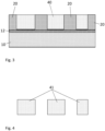
- FIG. 1 shows an example of a substrate 10 comprising a face 11 intended to receive a structurable resin 20.
- THE figures 2a And 2b schematically illustrate a process for manufacturing a metal watch component, according to one embodiment.
- the process is based on selective deposition of the metal using a layer of structured resin 20.
- the method comprises the steps of providing a substrate 10 comprising at least one face 11 on which a layer of structurable resin 20 is applied, directly or on one or more intermediate layers.
- the layer of resin 20 is then structured so as to form openings 21 in it which reveal an active surface 14, that is to say a surface intended to receive the metallic deposit.
- the active surface 14 can correspond to the exposed portions of the face 11 which are not covered by the resin 20, comprising a first primer layer (variant 1), or on the substrate itself (variant 2).
- the active surface 14 can also correspond to a first level 14' located on a resin layer, as illustrated in 3, defining in a similar manner the bottom 21 of the resin mold 20.
- Variant 4 shows the structured resin layer 20 having several levels (second levels 14" of the active surface 14).
- the shape of the contour of the openings 22 corresponds substantially in the shape of the component 41 to be produced.
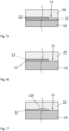
- a metal deposit 40 is then formed in the openings 21 of the structured resin layer 20 (which then forms a mold) by deposition of the metal (see the Figure 3 ).
- the mold By distributing the mold over several faces of the substrate, such as for example the two main faces of a substrate, which may for example have substantially the shape of a disk, it is possible to advantageously increase the number of components produced during of the same stage of a metal deposit.
- the metal deposit 40 formed is released from the resin 20 and the substrate 10 in order to obtain the component 41 (see the Figure 4 ).
- the particularity of the present process is that the metal deposit 40 is obtained by a chemical metallization process (electroless metal plating).
- the substrate 10 comprises a first primer layer 12 on the face 11, the metal deposit 40 being formed on the portions not being covered by the resin 20 (active surface 14).
- the first primer layer 12 is a catalytic layer or capable of being made catalytic.
- the first primer layer 12 may only partially cover the face 11 and/or the active surface 14.
- the first primer layer 12 may have a monatomic thickness or a certain thickness, or else be continuous or discontinuous.
- FIG. 5 illustrates the formation of the first primer layer 12 before deposition of the structurable resin 20, in which the primer layer 12 can cover the face 11 of the substrate 10 totally or partially.
- the first primer layer 12 can be formed on an adhesion and/or sacrificial layer 15 deposited on the substrate 10 before deposition of the structurable resin 20.
- adhesion is meant that the layer 15 facilitates the adhesion of the first primer layer 12, and by sacrificial, we mean that layer 15 facilitates the separation of the metal deposit from the substrate.
- FIG. 6 illustrates the formation of a first primer layer 12 on the face 11 of the substrate 10, as well as an insulating layer 13, that is to say a non-catalytic layer, formed on the first primer layer 12, before deposition of the structurable resin 20.
- the formation of layer 13 can be obtained by deposition or by reaction of the material of layer 12, such as for example metallic oxidation.
- FIG. 7 illustrates the first primer layer 12 which can comprise at least one portion of structured surface 120 and which is formed on the face 11.
- the first primer layer 12 can cover at least a portion of the face 11.
- at least a portion of surface we mean a part or the entirety of the surface.
- FIG 8 illustrates a variant in which the structurable resin 20 is deposited directly on the face 11 of the substrate 10 which can include a structuring 120 at least on a portion of the face 11.
- the substrate 10 can be made of a catalytic material or capable of being made catalytic.
- the first primer layer 12 is the face 11 of the substrate 10, and constitutes the first level 14' of the active surface 14 after obtaining the mold.
- FIG. 9 shows the variant of the Figure 6 after exposure and development of the structurable resin 20 and removal of the insulating layer 13 in the bottom of the openings 21 thus produced.
- the steps of applying the layer of structurable resin 20 and structuring the resin 20 are repeated in order to obtain a multi-level mold.
- the metal deposit 40 is formed in the openings 21 of the resin layer 20, once the multi-level mold has been formed.
- a multi-level mold is preferably produced with levels defined by geometries whose surface area increases starting from the first level on the substrate side, and whose geometry includes that of the opening made in the previous level, as by example illustrated in the figures 13 to 15 .
- a second conductive but non-catalytic primer layer 12' is formed on at least a portion of the second levels 14" of the active surface 14.
- the metal deposit 40 is formed at each of the steps of applying the layer of structurable resin 20 and of structuring the resin 20.
- the steps of applying the layer of structurable resin 20, of structuring the resin 20 and to form the metal deposit 40 are repeated in order to obtain a mold, filled with metal, at several levels.
- a second primer layer 12' which can be formed on at least a portion of the second levels 14" of the active surface 14 (see variant 4 in the figures 2a And 2b ), can be conductive and/or catalytic.
- it is possible to produce a multi-material component two levels being able to be produced in different materials.
- the same level of the component can also be made with more than one material, this making it possible to adapt the properties of each level of the component to the constraints to which it is subjected during its implementation in a mechanism.
- FIG. 10 illustrates the formation of a second primer layer 12' on the first level of a layer of structurable resin 20, before structuring.
- the second primer layer 12' can be formed on all or a portion of the face of the first level of the structurable resin layer 20.
- the second primer layer is in this case preferably conductive but not catalytic.
- FIG. 11 illustrates the formation of the second primer layer 12' on a first level of the structurable resin layer 20 after structuring.
- the primer layer 12' can be formed on all or a portion of the face of the first level of the structurable resin layer 20.
- the second primer layer is in this case preferably conductive but not catalytic.
- FIG. 12 illustrates the formation of the second primer layer 12' on a first level of the structurable resin layer 20 after structuring and after the deposition of a metal deposit 40 in the openings 21.
- the second primer layer 12' can be formed on all or a portion of the face of the first level of the structurable resin layer 20.
- the second primer layer 12' can therefore only cover the resin 20, the metal 40 or both.
- the primer layer can in this case be catalytic and/or conductive.
- FIG 13 illustrates the formation of a second level 20' of the structurable resin layer 20, after structuring of the previous level.
- a second primer layer 12' is included between a first level 20 of resin and the second level 20' of resin.
- the formation of the second level of resin 20' can be carried out before (for example Figure 15 ) or after (for example figures 10 to 14 ) the formation of a second primer layer 12' on the first level of structurable resin 20.
- the second level of resin 20' can be formed before the structuring of the first level of resin 20.
- the second primer layer is in this case preferably conductive but not catalytic.
- FIG. 14 illustrates the formation of a second level of resin 20', after structuring and deposition of the metal 40.
- a second primer layer 12' is formed on the first level of resin 20, before or after formation of the second level of resin 20'.
- the second primer layer 12' can in this case be catalytic and/or conductive.
- FIG. 15 illustrates the formation of a first primer layer 12 on the active surface 14 exposed by the openings 21 formed in the first level and of a second primer layer 12' on the surfaces parallel to the layers of the mold and exposed by the following levels of the resin mold.
- the active surface 14 comprises an exposed portion of the face 11 of the substrate 10 and an exposed portion of the first resin level 20 and can consist of a first primer layer 12 as well as a second primer layer 12 '.
- the method implements the use of a substrate 10 comprising a structure 16 in which the metal 40 can be deposited, for example by forming an active surface at the bottom of an opening of a layer of resin 20.
- the active surface 14 being in this case preferably obtained by the formation of a first primer layer 12, not illustrated but like that described in the examples of the figures 5 to 7 , made in the bottom of the structure 16 of the substrate.
- the active surface can be obtained by the formation of a catalytic layer or capable of being made catalytic or by the use of a catalytic substrate or capable of being made catalytic. catalytic.
- the prior structuring of the substrate offers the advantage of being able to produce a multilevel metal deposit 40 of which at least one level is obtained by the structuring of the substrate.
- the structurable resin mold can then include only one level, the other additional level(s) conforming to the structuring 16 of the substrate. It also makes it possible to produce geometries with non-vertical sides, such as bevels for example.
- the structure can also consist of a decoration which will be made on the substrate in the form of a negative imprint, to obtain the positive form on the component obtained. In this case, the negative imprint can be made set back from the main surface of the substrate which receives the layer of photostructurable resin, in a projecting manner, or a combination of the two.
- a variant still allows the geometries of the two techniques to be combined, such as for example a watch component comprising a drop and a hole in its center.
- the outer contour of the drop does not need to be as precise as the rest of the component and can result from the substrate structuring process.
- the through hole of the component can be produced during a single structuring and metal deposition step, in the two levels (the structure 16 and the resin layer 20) of the hybrid mold.
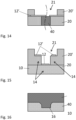
- FIG. 17 illustrates a variant of the method comprising a step of forming a structured layer 17 on the face 11 of the substrate 10.
- the structured layer 17 comprises openings 170 revealing an active surface 14, corresponding to that of the substrate 10 or to that of a layer covering the face 11 of the substrate 10, such as a first primer layer 12 or any variant proposed in the examples of the figures 1 to 8 .
- the blanks of the openings 170 of the structured layer 17 may comprise one or more patterns 171 so that the metal deposit 40 deposited in the opening(s) 170 comprises structured geometries such as threads, knurling or any other geometry involving structures. on the vertical sides of the metal deposit 40.
- the structured layer 17 can be deposited on the substrate after structuring, and can be made of any material, including a structurable resin.
- FIG. 18 illustrates a variant of the process in which an insert 18 is integrated into the metal deposit 40.
- the insert 18 can be made from a metallic or non-metallic catalytic material, such as for example a ceramic or other material, taking care to passivate its vertical sides in the case of a catalytic or conductive material.
- the insert 18 makes it possible to add, for example, complex structures (threads, etc.) on the sides of the deposited metal 40 as well as on its surfaces, the faces of the insert adjacent to the exterior faces of the metal deposit 40 produced being able to be structured and/or the insert 18 made of a particular material so as to allow extended functionalities of the component 41.
- the insert 18 can also be used for screwing, driving, guiding another component, etc., of the component 41 produced by the present process.
- the metal deposit 40 produced in a mold composed of a single layer of structured resin 20 or a mold composed of several levels of layers of structured resin 20 can be leveled or brought to thickness, for example by lapping.
- the thickness setting can be carried out for each step of deposition of the metal in a level.
- the layer of structurable resin 20 can also be set to thickness before structuring or after structuring.
- Figure 19 illustrates a machining process (counterboring, in this case) on a first face 42 of the metal deposit 40
- Figure 20 illustrates a machining process (for example beveling with a beveling tool 44 on a second face 43 of the metal deposit 40, after having previously turned over the layer of metallized resin 20.
- a support element 10' is mounted integrally (for example with a holding and/or sacrificial layer 15', as illustrated, to facilitate its holding and/or its separation) on the side of the metal deposit 40 (second face 42 of the metal deposit 40) opposite the substrate, the substrate then being removed (by delamination, dissolution, etc.), thus making it possible to release the first face of the metal deposit 40.
- This variant makes it possible in particular to produce non-vertical geometries, difficult to produce in a structured resin mold 20, in particular when the structuring is carried out by exposure to rays substantially perpendicular to the surface of the substrate.
- the variant illustrated in Figure 16 can be preceded by a step of filling the structuring produced in the substrate 10 with a layer of structurable resin 20 so as to obtain a level of the structured mold included in the thickness of the substrate and which can be defined by the structuring of the substrate and an optional step of structuring this resin layer 20.
- the process disclosed here makes it possible to economically produce complex, high-precision components up to medium-sized series.
- chemical metallization is advantageous over electrochemical metallization conventionally used for the growth of a metal in a structured resin mold.
- Chemical metallization is an auto-catalytic reaction which does not require the passage of a current in the deposition bath. For this reason, deposition facilities can be simpler and lower cost than in the case of galvanic deposition. It is also not necessary to know the area of the surfaces to be deposited in order to adapt the density of the deposition current.
- the growth of the deposit is also more regular and homogeneous than in the case of galvanic deposition, thus making it possible to eliminate the rectification step or at least to reduce the rectification time, for example, to obtain a mirror polish.
- the surfaces of the substrate 10 and of the structured resin 20 on which the metal is deposited must allow the initiation of the deposition, that is to say they must be made catalytic, or capable of being made catalytic, to a chemical deposition and made conductive, or capable of being made conductive, for an electrochemical deposition, and preferably cleaned.
- Obtaining a first primer layer 12 for the growth of the first level of the metal deposit can be obtained by any process allowing the formation of a catalytic layer or the activation of a material capable of being made catalytic.
- a material capable of being made catalytic we mean making it catalytic by changing its passivation potential or, in the case of a conductive and non-catalytic material, by putting it in contact with a catalytic material, which also makes it catalytic.
- a catalytic material which also makes it catalytic.
- gold is catalytic in a bath comprising boron, and conductive but not catalytic in a bath comprising phosphorus. In the latter case, it can be made catalytic by placing it in contact with a catalytic material, such as for example iron.
- a variant consists of depositing a catalytic material, such as for example platinum or palladium.
- a catalytic layer can be obtained by salt chemistry, which includes in particular the chemical reduction of catalytic metal salts, the use of photosensitive metal salts, such as for example silver salts (silver process), chlorides of gold, a solution of iron oxalate salts and platinum or palladium salts (platinotype process), or even the use of surface catalyst salts.
- the steps of deposition of photosensitive salts can include several steps whose order can be changed, certain steps can even be deleted.
- the deposition of photosensitive salts can be done on all or part of the primer surfaces to make them catalytic. This deposition can be done on a previously functionalized surface to allow better adhesion of the primer layer to the substrate. This step can therefore be carried out at several points in the process of producing the structured mold. Thus, it can for example be done before deposition of the first layer of structurable resin 20, after deposition of the structurable resin 20, and in this case, before or after exposure of the resin, or even after obtaining the mold by structuring. It is thus possible to generate a first partial or entire primer layer 12 on the first level of a mold, and this at several points in the process.
- the deposition of salts is generally carried out by immersion in a bath containing such salts, this technique being similar to the processes used in photography processes, particularly film photography.
- solutions containing silver salts such as a silver nitrate, a silver acetate, a silver oxalate, a silver halide or even a silver perchlorate can be used, although this last category presents risks linked to its handling.
- the salts are subjected to total or partial light exposure, in particular in order to make selective deposits, to freeze them on the surface.
- This revelation operation especially in the case of silver nitrate, gives metallic silver on the exposed parts, which makes the surface locally catalytic.
- the metallic silver is not catalytic, it is necessary to replace part of the metallic silver with platinum, palladium, gold or other precious metals. an oxidation-reduction reaction with salts of platinum, palladium, gold or other precious metals and the metal silver.
- An optional step of revealing the salts exposed in a developer, such as hydroquinone, makes it possible to obtain larger metal aggregates, thus making the surface more catalytic, which may be preferable to promote the initiation of growth in a chemical metallization process.
- a developer such as hydroquinone
- the metal deposition 40 can use a first step of metal deposition by chemical means on a first level, from a first layer of catalytic primer 12, and a subsequent step of metal deposition by electrochemical means (electrodeposition) on a next level, from a second primer layer 12' constituted by a conductive and/or catalytic surface (for example, in the case of a primer layer by metal salts, sufficiently close spacing of the catalytic salts allows growth by nucleation of the metal deposit).
- the substrate 10 and the structured resin 20 comprise an active surface 14 made or capable of being made catalytic from which the metal deposition is made.
- the substrate 10 can itself be non-catalytic and comprise, on its face 11, a first primer layer 12.
- the substrate 10 can comprise a silicon plate on the surface (face 11) of which is produced a first layer of catalytic primer 12.
- the substrate 10 may comprise a glass or a ceramic.
- the primer layer 12 is a conductive layer, this may in particular be a layer of nickel, copper, iron, platinum, palladium, stainless steel, gold or another metal and/or a combination of these layers.
- the substrate 10 can be made of a catalytic metallic material or capable of being made catalytic and can comprise, for example, an alloy comprising at least one metallic element chosen from aluminum, copper, iron, platinum, palladium, nickel, gold, or other suitable metal or alloy.
- a metal substrate 10 has the advantage of having a thermal expansion coefficient close to that of the deposited metal.
- a nickel phosphorus (NiP) is typically deposited at a temperature between approximately 70°C to 95°C. As it cools, a silicon substrate could strain slightly. This effect will be reduced with a metal substrate whose thermal expansion coefficient is close to that of the material deposited.
- catalytic material substrates may include a polymer, ceramic or glass doped with catalytic elements such as catalytic metal nano- and/or microparticles.
- a catalytic ceramic such as titanium nitride for example, can be used.
- the substrate 10 can be made of a non-catalytic and/or non-conductive material such as a polymer, a composite, a glass, a ceramic or a non-catalytic metal, the face 11 of the substrate 10 receiving the deposit 40 then being made catalytic, in part or entirely, by appropriate means.
- a non-catalytic and/or non-conductive material such as a polymer, a composite, a glass, a ceramic or a non-catalytic metal
- the face 11 of the substrate 10 receiving the deposit 40 then being made catalytic, in part or entirely, by appropriate means.
- Metals with low adhesion power such as gold, stainless steel, certain chromium alloys or aluminum may be favored to facilitate the removal of components.
- metal salts or chlorides can be used, such as for example salts of precious elements (such as silver, platinum, palladium or even gold). These salts may or may not be photo-reduced and/or chemically reduced.
- a second primer layer can be obtained by depositing a conductive material.
- This layer can be formed in different ways, such as for example by vapor phase deposition (generally PVD) or chemical phase deposition (generally CVD).
- PVD vapor phase deposition
- CVD chemical phase deposition
- different processes can be used, such as for example sparing or lift-off, to cover only the desired part of the surface, or even etching after deposition, to remove the parts not covered. desired layer.
- the structurable resin 20 will be chosen from the group comprising photosensitive resins, these being able to be of positive or negative type.
- the resin 20 is applied to the face 11 of the substrate 10.
- the resin 20 comprises a negative photosensitive resin based on epoxy.
- the resin may comprise an octofunctional epoxy resin of the SU-8 type which polymerizes under the action of UV radiation. Other resins can react to x-ray type radiation.
- the structuring of the resin layer 20 consists of irradiating through a mask 30 (see the figure 2 ), the layer of resin 20 previously applied to the face 11 of the substrate 10. This layer of resin 20 is polymerized according to the pattern of the mask 30 and the unpolymerized parts of the layer are eliminated by chemical means. The remaining part of resin 20 forms a mold comprising one or more cavities 21 and defining the contour 22 of the component 41.
- annealing of the photosensitive resin layer causes polymerization in areas that have received UV radiation. This polymerized part becomes insensitive to most solvents as opposed to the non-irradiated areas which are dissolved by a solvent.
- the structuring of the resin layer 20 consists of developing the non-exposed areas of the photosensitive resin layer 20 to reveal in places, that is to say in the openings 21, the face 11 of the substrate 10 (these exposed portions of face 11 then correspond to active surface 14).
- this operation can be carried out by dissolving the non-exposed areas using a solvent chosen from GBL (gammabutyrolactone) and PGMEA (propylene glycol methyl ethyl acetate).
- GBL gammabutyrolactone
- PGMEA propylene glycol methyl ethyl acetate
- the resin layer 20 can be deposited on the substrate 10 with a thickness of at least 50 ⁇ m, or even at least 100 ⁇ m. Depending on the type of resin used, it may be necessary to successively deposit more than one layer of resin 20 on the substrate 10 in order to achieve the thickness of the desired resin layer.
- the structurable resin will be chosen from the group comprising radiation-curable resins.
- the structuring is preferably done by exposure to an electron beam source.
- This process is most often referred to as e-beam lithography and has a number of advantages, including increased precision, in the nanometer range. While engraving by “e-beam lithography” is most often carried out without a mask, in a serial manner, it is also possible to combine it with the use of masks, which makes the process faster and overcomes speed problems. encountered in the application of the process without a mask. Such a possibility has already been presented in the documents US3544790 And US3681103 .
- a metal deposit 40 is then produced in the openings 21 of the resin mold 20 by a chemical metallization process, this chemical metallization being able to be combined, in a subsequent step, with a galvanic metallization step.
- the metal deposit 40 can be raw up to a thickness less than that of the resin layer 20, substantially the same thickness, or even beyond the upper surface of the resin 20.
- Figure 3 shows a metal deposit 40 produced substantially at the same thickness as the resin layer 20.
- the metal deposit 40 may comprise a layer of chemical nickel (or one of its alloys) or a layer obtained by chemical nickel plating.
- Electroless nickel plating is an electroless deposition process that occurs in the presence of a reducing agent, such as sodium hydrophosphite (NaPO 2 H 2 ⁇ H 2 O) that reacts with metal ions to deposit the metal.
- a reducing agent such as sodium hydrophosphite (NaPO 2 H 2 ⁇ H 2 O) that reacts with metal ions to deposit the metal.
- Nickel can be deposited with different percentages of phosphorus, for example between 2% and 5% (low phosphorus content), between 5% and 8% (medium phosphorus content) or between 8% and 15% (high phosphorus content). ), or even between 15% and 20%.
- the hardness without heat treatment of the chemical phosphorus nickel deposit is typically between 520 HV for low phosphorus content and 650 HV for high phosphorus content.
- compositions allowing thick deposits can be used, and more particularly but not limited to, baths containing at least one element from a group including cobalt, boron, phosphorus, nickel, copper and gold.
- baths containing at least one element from a group including cobalt, boron, phosphorus, nickel, copper and gold can be used, and more particularly but not limited to, baths containing at least one element from a group including cobalt, boron, phosphorus, nickel, copper and gold.
- These metals or alloys can further incorporate one or more elements including tungsten, molybdenum, chromium, tin, iron, to obtain alloys with modified properties.
- salts of these metals added to the base baths are co-reduced to improve properties such as hardness, coefficient of friction, magnetism or even the properties of expansion and thermoelasticity.
- the metal deposit 40 can be produced in the openings 21 with a thickness of at least 50 ⁇ m and preferably at least 100 ⁇ m. Thicknesses of the metal deposit 40 greater than 150 ⁇ m, or even 500 ⁇ m, are also possible. The thickness of the metal deposit 40 can be determined by the speed and time of deposition.
- a component 41 of complex shape at several levels can be produced in several stages, each stage being able to include the deposition then the structuring of a layer of resin 20 and the growth of a metal deposit 40 in the layer of structured resin 20.
- all the steps of structuring the multi-stage mold can be carried out before filling the mold with the metal deposit.
- the levels of the component thus manufactured are closely linked to each other thanks to the precision of the structuring of the mold.
- the metal deposit 40 may be necessary to level its upper face by a lapping operation, polishing, chemical machining, or any other equivalent means. Depending on the solidity of the substrate 10, this leveling operation can be done immediately after the chemical deposition, before the separation of the metal deposit 40 from the substrate 10. If necessary, the lower face of the component can also be subjected to the same operations, before or after separation from the mold. To carry out this operation before separation of the mold, it can be advantageous to hold the parts rigidly on a support element 10' as illustrated in Figure 20 .
- a mechanical machining operation of the components 41 on their substrate 10 has the advantage of benefiting from increased precision and repeatability of the geometries obtained due to the extremely precise positioning of the parts together on the one hand and of the reduction in the chain of odds resulting from this positioning.
- the substrate 10 so that the geometry of the component 41 obtained includes the inverse geometries of these geometries, as for example illustrated in Figure 16 .
- surface structures such as finishes, for example watchmaking decorations (Côtes de Genève, perlage, satin finishing, sunburst, etc.), engraving of information or even geometries including beveling, countersinking or other.
- the step of releasing the metal deposit 40 from the resin 20 and the substrate 10 can be carried out by dissolving the substrate 10 when the latter is soluble, as is the case with a silicon or aluminum substrate, as well as of the resin mold 20.
- the step of releasing the metal deposit 40 can also be carried out by dissolving the resin mold 20 only, when the metal deposit 40 is entirely supported by the mold 20, as illustrated on variants 3 and 4 of the figure 2a and 4 and 5 of the figure 2b .
- the first primer layer 12 can act as a sacrificial layer 15 which is dissolved, for example a layer 12 of titanium, zinc or aluminum, releasing the deposit 40 of the substrate 10, which can be constituted of a ceramic, a glass or a metal, such as nickel, which resists the chemical agent used for the dissolution of the primer layer 12.
- the Figure 4 represents the metal deposit 40 forming the component 41, released from the resin 20 and the substrate 10.
- the step of releasing the component 41 can also be carried out by mechanical separation (stripping), for example by delamination, of the metal deposit 40 from the substrate 10 and removal, for example by chemical dissolution, of the resin 20. Mechanical separation is possible when the adhesion between the deposit 40 and the substrate 10 is moderate. This is for example the case for a substrate 10 comprising a metallic layer 12 of chrome which allows moderate adhesion.
Description
La présente invention concerne un procédé pour la fabrication d'un composant horloger métallique de forme complexe avec une haute précision, de manière économique. La présente invention concerne également le composant horloger ainsi obtenu et une pièce d'horlogerie comprenant ledit composant.The present invention relates to a method for manufacturing a metallic watch component of complex shape with high precision, in an economical manner. The present invention also relates to the watch component thus obtained and a timepiece comprising said component.
Dans le but de réaliser des pièces ou composants mécaniques d'une très grande précision et ayant des épaisseurs de quelques centaines de microns, voire jusqu'à plusieurs millimètres, un procédé de fabrication par irradiation d'une couche photosensible aux rayons ultraviolets suivie d'une étape d'électroformage est connu et est décrit par exemple dans le brevet
Les dépôts réalisés par électrodéposition tendent à avoir une surface inhomogène et irrégulière dû aux lignes de champs de courant pendant la croissance galvanique. La réalisation de composants par électrodéposition nécessite donc de déposer la couche avec une surépaisseur et une étape supplémentaire de rectification (par exemple par polissage) afin d'obtenir une surface des composants acceptable.Deposits made by electrodeposition tend to have an inhomogeneous and irregular surface due to the current field lines during galvanic growth. The production of components by electrodeposition therefore requires depositing the layer with an extra thickness and an additional rectification step (for example by polishing) in order to obtain an acceptable surface of the components.
Une variante de ce procédé est notamment présentée dans le brevet
Le document
La présente invention concerne un procédé pour la fabrication d'un composant horloger tel que celui objet des revendications 1 à 19, du composant horloger qui en résulte ainsi que d'une pièce d'horlogerie comprenant un tel composant.The present invention relates to a method for manufacturing a watch component such as that which is the subject of
En particulier, la présente invention concerne un procédé comprenant les étapes de:
- se munir d'un substrat comportant au moins une face destinée à recevoir une résine structurable;
- appliquer une couche de résine structurable sur ladite au moins une face;
- structurer la résine de manière à former un moule comprenant des ouvertures laissant apparaitre une surface active, la surface active comportant au moins premier niveau;
- former un dépôt métallique dans les ouvertures du moule en résine;
- libérer le dépôt métallique du moule et du substrat de sorte à obtenir le composant;
- une première couche d'amorce étant formée sur, ou réalisée par, au moins une partie du premier niveau de ladite surface active, avant l'étape de former un dépôt métallique, cette première couche d'amorce étant catalytique ou susceptible d'être rendue catalytique;
- le dépôt métallique étant formé par un procédé de métallisation chimique exempt d'activation électrique (comme par exemple l'autocatalyse), dans lequel l'épaisseur de la résine est d'au moins 50 µm et le dépôt métallique est cru jusqu'à la même hauteur que la résine ou au-delà, de sorte à avoir une épaisseur d'au moins 50 µm, ou d'au moins 100 µm ou supérieur à 150 µm ou 500 µm.
- provide a substrate comprising at least one face intended to receive a structurable resin;
- apply a layer of structurable resin on said at least one face;
- structuring the resin so as to form a mold comprising openings revealing an active surface, the active surface comprising at least first level;
- forming a metal deposit in the openings of the resin mold;
- releasing the metal deposit from the mold and the substrate so as to obtain the component;
- a first primer layer being formed on, or produced by, at least part of the first level of said active surface, before the step of forming a metal deposit, this first primer layer being catalytic or capable of being rendered catalytic;
- the metal deposit being formed by a chemical metallization process free from electrical activation (such as for example autocatalysis), in which the thickness of the resin is at least 50 µm and the metal deposit is raw up to the same height as the resin or beyond, so as to have a thickness of at least 50 µm, or at least 100 µm or greater than 150 µm or 500 µm.
La surface active peut être constituée de surfaces parallèles à la face du substrat et peut comporter un premier niveau qui est le niveau le plus proche de, ou confondu avec, la face. La surface active peut comporter un ou plusieurs deuxièmes niveaux constitués des prochaines surfaces d'un moule à plusieurs étages.The active surface may consist of surfaces parallel to the face of the substrate and may include a first level which is the level closest to, or coincident with, the face. The active surface may include one or more second levels consisting of the next surfaces of a multi-stage mold.
Le dépôt métallique a de préférence une épaisseur d'au moins 100 µm. Dans le présent texte, le terme « métallisation chimique » fait exclusivement référence aux métallisations chimiques exemptes d'activation électrique, comme par exemple l'autocatalyse. De même, le terme « métallisation électrochimique » fait référence aux métallisations activées par un courant, comme l'électrodéposition et la galvanoplastie.The metal deposit preferably has a thickness of at least 100 μm. In this text, the term “chemical metallization” refers exclusively to chemical metallizations free from electrical activation, such as for example autocatalysis. Likewise, the term "electrochemical metallization" refers to current-activated metallizations, such as electrodeposition and electroplating.
Le procédé selon l'invention peut en outre comporter au moins une autre étape, incluant notamment une étape de:
- structurer le substrat de manière à obtenir une surface non plane et/ou non constante de dépôt de la résine, par exemple pour former des géométries supplémentaires fonctionnelles et/ou de décoration;
- avant dépôt de la résine structurable, recouvrir au moins partiellement la face catalytique d'une couche protectrice qui sera retirée dans une étape ultérieure, avant l'étape de dépôt métallique;
- rendre catalytique une partie au moins des surfaces dégagées après au moins une des étapes de structuration du moule en résine;
- mettre à niveau la résine structurable, avant et/ou entre et/ou après au moins une des étapes de structuration;
- mettre à niveau le dépôt métallique, en fin de dépôt et/ou entre les étapes de dépôt successives ;
- entre les étapes de formation et de libération du dépôt métallique, procéder à des opérations d'usinage mécanique, chimique ou autre, sur une ou plusieurs faces du dépôt;
- procéder à des étapes supplémentaires d'usinage sur au moins une autre face du dépôt métallique en fixant, le cas échéant, un élément de support à la face supérieure du dépôt avant de retirer le substrat, de manière à libérer la face inférieure du dépôt; ou
- intégrer au moins un composant réalisé au préalable en le positionnant par rapport au substrat et/ou au moule avant l'étape de formation du dépôt métallique, de manière à intégrer le au moins un composant dans la pièce réalisée par le procédé selon l'invention.
- structure the substrate so as to obtain a non-flat and/or non-constant surface for deposition of the resin, for example to form additional functional and/or decorative geometries;
- before deposition of the structurable resin, cover at least partially the catalytic face with a protective layer which will be removed in a subsequent step, before the metal deposition step;
- make at least part of the surfaces released after at least one of the steps of structuring the resin mold catalytic;
- leveling the structurable resin, before and/or between and/or after at least one of the structuring steps;
- level the metal deposit, at the end of the deposit and/or between successive deposit stages;
- between the stages of formation and release of the metal deposit, carry out mechanical, chemical or other machining operations on one or more faces of the deposit;
- carry out additional machining steps on at least one other face of the metal deposit by fixing, where appropriate, a support element to the upper face of the deposit before removing the substrate, so as to release the lower face of the deposit; Or
- integrate at least one component produced beforehand by positioning it relative to the substrate and/or the mold before the step of forming the metal deposit, so as to integrate the at least one component into the part produced by the method according to the invention .
Dans le présent texte, tous les pourcentages sont massiques lorsque pas spécifiés autrement.In this text, all percentages are by mass when not otherwise specified.
Le dépôt métallique peut être réalisé dans tout métal apte à être déposé par procédé de métallisation chimique, notamment un métal à base de nickel ou un alliage au moins en partie métallique à base de nickel; à titre d'exemple non limitatif, un dépôt de nickel phosphore peut être réalisé à partir d'un bain de nickel chimique comprenant l'élément phosphore. Le dépôt peut comprendre entre 2% et 20% de phosphore, de préférence entre 4% et 15% et peut avoir une dureté de plus de 400Hv, voire de 500Hv.The metal deposition can be carried out in any metal capable of being deposited by a chemical metallization process, in particular a metal based on nickel or an alloy at least partly metallic based on nickel; by way of non-limiting example, a deposit of nickel phosphorus can be made from a bath of chemical nickel comprising the element phosphorus. The deposit can comprise between 2% and 20% phosphorus, preferably between 4% and 15% and can have a hardness of more than 400Hv, or even 500Hv.
Selon un mode de réalisation, la résine structurable est déposée avec une épaisseur supérieure à 100 µm; l'épaisseur pouvant être obtenue en une ou plusieurs étapes de dépôt. Le dépôt peut être obtenu de différentes manières, comme par exemple par spin-coating ou par application d'un film adhésif.According to one embodiment, the structurable resin is deposited with a thickness greater than 100 µm; the thickness that can be obtained in one or more deposition steps. The deposit can be obtained in different ways, such as for example by spin-coating or by application of an adhesive film.
Le procédé divulgué ici combine les avantages de la déposition chimique combinée avec une résine structurée, c'est-à-dire, la possibilité de fabriquer économiquement un composant complexe de haute précision sans les inconvénients qu'apporte la galvanoplastie, notamment les problèmes de la distribution du courant à l'échelle du substrat entier et des structures dans le moule de résine.The process disclosed here combines the advantages of chemical deposition combined with a structured resin, that is to say, the possibility of economically manufacturing a complex component of high precision without the disadvantages brought by electroplating, in particular the problems of current distribution across the entire substrate and structures in the resin mold.
Des exemples de mise en oeuvre de l'invention sont indiqués dans la description illustrée par les figures annexées dans lesquelles:
- la
figure 1 montre un exemple d'un substrat comportant une face comprenant une première couche d'amorce, destinée à recevoir une résine structurable, selon un mode de réalisation; - les
figures 2a et2b illustrent de manière schématique un procédé pour la fabrication d'un composant horloger métallique, selon un mode de réalisation; - la
figure 3 montre un dépôt métallique formé dans des ouvertures d'un moule de la résine sur le substrat, selon un mode de réalisation; - la
figure 4 représente le dépôt métallique libéré de la résine et du substrat; - La
figure 5 illustre la formation de la première couche d'amorce, selon un mode de réalisation; - la
figure 6 illustre la formation de la première couche d'amorce, selon un autre mode de réalisation; - la
figure 7 illustre la formation de la première couche d'amorce, encore selon un autre mode de réalisation; - la
figure 8 illustre une étape de dépôt de la résine, selon un mode de réalisation; - la
figure 9 montre la formation de la première couche d'amorce selon lafigure 6 après exposition et développement de la résine, selon un mode de réalisation; - la
figure 10 illustre la formation de la deuxième couche d'amorce sur un premier niveau de la résine, selon un mode de réalisation; - la
figure 11 illustre la formation d'une deuxième couche d'amorce sur un premier niveau de la résine, selon un autre mode de réalisation; - la
figure 12 illustre la formation d'une deuxième couche d'amorce sur un premier niveau de la résine, encore selon un autre mode de réalisation; - la
figure 13 illustre la formation d'un deuxième niveau de la résine structurable, selon un mode de réalisation; - la
figure 14 illustre la formation d'un deuxième niveau de la résine structurable, selon un autre mode de réalisation; - la
figure 15 illustre la formation d'une première et d'une deuxième couches d'amorce, encore selon un autre mode de réalisation; - la
figure 16 , représente le substrat comportant une structure et le dépôt métallique remplissant cette structure, selon un mode de réalisation; - la
figure 17 illustre la formation d'une première couche structurée sur le substrat, selon un mode de réalisation; - la
figure 18 montre un insert inséré dans le dépôt métallique, selon un mode de réalisation; - la
figure 19 représente un procédé d'usinage sur une face du dépôt métallique, selon un mode de réalisation; et - la
figure 20 représente un procédé d'usinage sur une face du dépôt métallique, selon un autre mode de réalisation.
- there
figure 1 shows an example of a substrate comprising a face comprising a first primer layer, intended to receive a structurable resin, according to one embodiment; - THE
figures 2a And2b schematically illustrate a process for manufacturing a metal watch component, according to one embodiment; - there
Figure 3 shows a metal deposit formed in openings of a mold of the resin on the substrate, according to one embodiment; - there
Figure 4 represents the metal deposit released from the resin and the substrate; - There
Figure 5 illustrates the formation of the first primer layer, according to one embodiment; - there
Figure 6 illustrates the formation of the first primer layer, according to another embodiment; - there
Figure 7 illustrates the formation of the first primer layer, according to yet another embodiment; - there
figure 8 illustrates a step of depositing the resin, according to one embodiment; - there
Figure 9 shows the formation of the first primer layer according to theFigure 6 after exposure and development of the resin, according to one embodiment; - there
Figure 10 illustrates the formation of the second primer layer on a first level of the resin, according to one embodiment; - there
Figure 11 illustrates the formation of a second primer layer on a first level of the resin, according to another embodiment; - there
Figure 12 illustrates the formation of a second primer layer on a first level of the resin, according to yet another embodiment; - there
Figure 13 illustrates the formation of a second level of the structurable resin, according to one embodiment; - there
Figure 14 illustrates the formation of a second level of the structurable resin, according to another embodiment; - there
Figure 15 illustrates the formation of a first and a second primer layers, according to yet another embodiment; - there
Figure 16 , represents the substrate comprising a structure and the metal deposit filling this structure, according to one embodiment; - there
Figure 17 illustrates the formation of a first structured layer on the substrate, according to one embodiment; - there
Figure 18 shows an insert inserted into the metal deposit, according to one embodiment; - there
Figure 19 represents a machining process on one face of the metal deposit, according to one embodiment; And - there
Figure 20 represents a machining process on one face of the metal deposit, according to another embodiment.
La
Les
Dans les grandes lignes, le procédé comprend les étapes de fournir un substrat 10 comportant au moins une face 11 sur laquelle est appliquée, directement ou sur une ou plusieurs couches intermédiaires, une couche de résine structurable 20. La couche de résine 20 est ensuite structurée de manière à former dans celle-ci des ouvertures 21 qui laissent apparaitre une surface active 14, c'est-à-dire une surface destinée à recevoir le dépôt métallique. Dans l'exemple de la
Dans l'exemple des
La
La
La
La
La
Dans un mode de réalisation, les étapes d'appliquer la couche de résine structurable 20 et de structurer la résine 20 sont répétées afin d'obtenir un moule à plusieurs niveaux. Le dépôt métallique 40 est formé dans les ouvertures 21 de la couche de résine 20, une fois que le moule à plusieurs niveaux a été formé.In one embodiment, the steps of applying the layer of
Un moule à plusieurs niveaux est de manière préférentielle réalisé avec des niveaux définis par des géométries dont la superficie va de manière croissante en partant du premier niveau côté substrat, et dont la géométrie comprend celle de l'ouverture réalisée dans le niveau précédent, comme par exemple illustré dans les
Afin de permettre une croissance homogène du dépôt métallique multiniveaux, lorsqu'il est réalisé en une seule étape, il est préférable de former une deuxième couche d'amorce 12' conductrice mais non catalytique, sur au moins une portion des deuxièmes niveaux 14" de la surface active 14.In order to allow homogeneous growth of the multilevel metal deposit, when it is carried out in a single step, it is preferable to form a second conductive but
Dans une variante, le dépôt métallique 40 est formé à chacune des étapes d'appliquer la couche de résine structurable 20 et de structurer la résine 20. Autrement dit, les étapes d'appliquer la couche de résine structurable 20, de structurer la résine 20 et de former le dépôt métallique 40 sont répétées afin d'obtenir un moule, rempli de métal, à plusieurs niveaux. Dans ce cas, une deuxième couche d'amorce 12', qui peut être formée sur au moins une portion des deuxièmes niveaux 14" de la surface active 14 (voir la variante ④ dans les
La
La
La
La
La
La
Dans l'exemple de la
La structuration préalable du substrat offre l'avantage de pouvoir réaliser un dépôt métallique 40 multiniveaux dont au moins un niveau est obtenu par la structuration du substrat. Le moule en résine structurable peut alors ne comprendre qu'un seul niveau, le ou les autres niveaux supplémentaires étant conformes à la structuration 16 du substrat. Il permet aussi de réaliser des géométries à flancs non verticaux, tels que des anglages par exemple. La structure peut également consister en une décoration qui sera réalisée sur le substrat sous une forme d'empreinte négative, pour en obtenir la forme positive sur le composant obtenu. Dans ce cas, l'empreinte négative peut être réalisée en retrait de la surface principale du substrat qui reçoit la couche de résine photostructurable, de manière saillante, ou une combinaison des deux.The prior structuring of the substrate offers the advantage of being able to produce a
Une variante permet encore de combiner les géométries des deux techniques, comme par exemple un composant horloger comportant une goutte et un trou en son centre. Le contour extérieur de la goutte n'a pas besoin d'être aussi précis que le reste du composant et peut résulter du procédé de structuration du substrat. Le trou traversant du composant peut être réalisé lors d'une seule étape de structuration et de déposition métallique, dans les deux niveaux (la structure 16 et la couche de résine 20) du moule hybride.A variant still allows the geometries of the two techniques to be combined, such as for example a watch component comprising a drop and a hole in its center. The outer contour of the drop does not need to be as precise as the rest of the component and can result from the substrate structuring process. The through hole of the component can be produced during a single structuring and metal deposition step, in the two levels (the
La
La
Le dépôt métallique 40 réalisé dans un moule composé d'une seule couche de résine 20 structurée ou un moule composé de plusieurs niveaux de couches de résine 20 structuré peut être nivelé ou mis à l'épaisseur, par exemple par rodage. La mise à l'épaisseur peut être réalisée pour chaque étape de déposition du métal dans un niveau. La couche de résine 20 structurable peut également être mise à l'épaisseur avant la structuration ou après la structuration.The
D'autres procédés de surfaçage ou d'usinage après la déposition du métal 40 sont possibles notamment, par exemple, la
Ainsi, la variante illustrée en
Sans sortir du cadre de l'invention, les variantes décrites précédemment et illustrées de manière non exhaustive dans les
Le procédé divulgué ici permet de produire économiquement jusqu'à la moyenne série des composants complexes de haute précision. D'autre part, la métallisation chimique est avantageuse par rapport à la métallisation électrochimique conventionnellement utilisée pour la croissance d'un métal dans un moule de résine structuré. La métallisation chimique est une réaction auto-catalytique qui ne nécessite pas le passage d'un courant dans le bain de déposition. Pour cette raison, les installations de déposition peuvent être plus simples et de coût moindre que dans le cas de la déposition galvanique. Il n'est non plus pas nécessaire de connaître l'aire des surfaces à déposer afin d'adapter la densité du courant de déposition. La croissance du dépôt est également plus régulière et homogène que dans le cas d'une déposition galvanique, permettant ainsi d'éliminer l'étape de rectification ou du moins de réduire le temps de rectification, par exemple, pour obtenir un poli miroir.The process disclosed here makes it possible to economically produce complex, high-precision components up to medium-sized series. On the other hand, chemical metallization is advantageous over electrochemical metallization conventionally used for the growth of a metal in a structured resin mold. Chemical metallization is an auto-catalytic reaction which does not require the passage of a current in the deposition bath. For this reason, deposition facilities can be simpler and lower cost than in the case of galvanic deposition. It is also not necessary to know the area of the surfaces to be deposited in order to adapt the density of the deposition current. The growth of the deposit is also more regular and homogeneous than in the case of galvanic deposition, thus making it possible to eliminate the rectification step or at least to reduce the rectification time, for example, to obtain a mirror polish.
Les surfaces du substrat 10 et de la résine structurée 20 sur lesquelles le métal est déposé doivent permettre l'amorce de la déposition, c'est-à-dire qu'elles doivent être rendues catalytiques, ou susceptibles d'être rendues catalytiques, pour un dépôt chimique et rendues conductrices, ou susceptible d'être rendues conductrices, pour un dépôt électrochimique, et préférablement nettoyées.The surfaces of the
L'obtention d'une première couche d'amorce 12 pour la croissance du premier niveau du dépôt métallique peut être obtenue par tout procédé permettant la formation d'une couche catalytique ou l'activation d'un matériau susceptible d'être rendu catalytique.Obtaining a
Par activation d'un matériau susceptible d'être rendu catalytique, on entend le rendre catalytique en changeant son potentiel de passivation ou, dans le cas d'un matériau conducteur et non catalytique, en le mettant en contact avec un matériau catalytique, ce qui le rend lui aussi catalytique. A titre d'exemple, l'or est catalytique dans un bain comprenant du bore, et conducteur mais non catalytique dans un bain comprenant du phosphore. Dans ce dernier cas, il peut être rendu catalytique en le mettant en contact avec un matériau catalytique, comme par exemple le fer.By activation of a material capable of being made catalytic, we mean making it catalytic by changing its passivation potential or, in the case of a conductive and non-catalytic material, by putting it in contact with a catalytic material, which also makes it catalytic. For example, gold is catalytic in a bath comprising boron, and conductive but not catalytic in a bath comprising phosphorus. In the latter case, it can be made catalytic by placing it in contact with a catalytic material, such as for example iron.
Dans le cas de la formation d'une couche catalytique, une variante consiste à déposer un matériau catalytique, comme par exemple le platine ou le palladium. De manière alternative, une couche catalytique peut être obtenue par chimie des sels, qui comprend notamment la réduction chimique de sels métalliques catalytiques, l'emploi de sels métalliques photosensibles, comme par exemple des sels d'argent (procédé argentique), des chlorures d'or, une solution de sels d'oxalate de fer et de sels de platine ou palladium (procédé platinotypie), ou encore l'emploi de sels catalyseurs en surface. Les étapes de dépôt de sels photosensibles peuvent comprendre plusieurs étapes dont l'ordre peut être changé, certaines étapes pouvant même être supprimées.In the case of the formation of a catalytic layer, a variant consists of depositing a catalytic material, such as for example platinum or palladium. Alternatively, a catalytic layer can be obtained by salt chemistry, which includes in particular the chemical reduction of catalytic metal salts, the use of photosensitive metal salts, such as for example silver salts (silver process), chlorides of gold, a solution of iron oxalate salts and platinum or palladium salts (platinotype process), or even the use of surface catalyst salts. The steps of deposition of photosensitive salts can include several steps whose order can be changed, certain steps can even be deleted.
La déposition de sels photosensibles peut se faire sur toute ou partie des surfaces d'amorce pour les rendre catalytiques. Cette déposition peut se faire sur une surface préalablement fonctionnalisée pour permettre une meilleure adhésion de la couche d'amorce sur le substrat. Cette étape peut donc être réalisée à plusieurs moments du procédé de réalisation du moule structuré. Ainsi, elle peut par exemple se faire avant dépôt de la première couche de résine 20 structurable, après dépôt de la résine 20 structurable, et dans ce cas, avant ou après exposition de la résine, ou encore après obtention du moule par structuration. Il est ainsi possible de générer une première couche d'amorce 12 partielle ou entière sur le premier niveau d'un moule, et ce à plusieurs moments du procédés.The deposition of photosensitive salts can be done on all or part of the primer surfaces to make them catalytic. This deposition can be done on a previously functionalized surface to allow better adhesion of the primer layer to the substrate. This step can therefore be carried out at several points in the process of producing the structured mold. Thus, it can for example be done before deposition of the first layer of
La déposition des sels est généralement réalisée par immersion dans un bain contenant de tels sels, cette technique s'apparentant aux procédés utilisés dans les procédés de photographie, notamment argentique. Ainsi, il peut être fait appel à des solutions contentant des sels d'argent comme un nitrate d'argent, un acétate d'argent, un oxalate d'argent, un halogénure d'argent ou encore un perchlorate d'argent, bien que cette dernière catégorie présente des risques liées à sa manipulation.The deposition of salts is generally carried out by immersion in a bath containing such salts, this technique being similar to the processes used in photography processes, particularly film photography. Thus, solutions containing silver salts such as a silver nitrate, a silver acetate, a silver oxalate, a silver halide or even a silver perchlorate can be used, although this last category presents risks linked to its handling.
Une fois déposés et séchés, les sels sont soumis à une exposition lumineuse totale ou partielle, notamment afin de procéder des dépôts sélectifs, pour les figer sur la surface. Cette opération de révélation, notamment dans le cas du nitrate d'argent, donne de l'argent métallique sur les parties exposées, ce qui rend la surface localement catalytique. Pour les bains electroless où l'argent métal n'est pas catalytique, il est nécessaire de procéder à la substitution d'une partie de l'argent métallique par du platine, du palladium ,de l'or ou d'autre métaux précieux par une réaction d'oxydo-réduction avec des sels de platine, de palladium, d'or ou d'autre métaux précieux et le métal argent.Once deposited and dried, the salts are subjected to total or partial light exposure, in particular in order to make selective deposits, to freeze them on the surface. This revelation operation, especially in the case of silver nitrate, gives metallic silver on the exposed parts, which makes the surface locally catalytic. For electroless baths where the metallic silver is not catalytic, it is necessary to replace part of the metallic silver with platinum, palladium, gold or other precious metals. an oxidation-reduction reaction with salts of platinum, palladium, gold or other precious metals and the metal silver.
Une étape optionnelle de révélation des sels insolés dans un révélateur, comme par exemple de l'hydroquinone, permet d'obtenir des agrégats métalliques plus gros, rendant ainsi la surface plus catalytique, ce qui peut être préférable pour favoriser l'amorce de croissance dans un procédé de métallisation chimique. En prolongeant la croissance des agrégats métalliques, la surface peut passer de catalytique uniquement à conductrice, ce qui peut dans ce cas permettre la croissance par un procédé d'électrodéposition.An optional step of revealing the salts exposed in a developer, such as hydroquinone, makes it possible to obtain larger metal aggregates, thus making the surface more catalytic, which may be preferable to promote the initiation of growth in a chemical metallization process. By extending the growth of the metal aggregates, the surface can change from catalytic only to conductive, which in this case can allow growth through an electrodeposition process.
Ainsi, sans sortir du cadre de l'invention, le dépôt métallique 40 peut faire appel à une première étape de dépôt métallique par voie chimique sur un premier niveau, à partir d'une première couche d'amorce 12 catalytique, et une étape postérieure de dépôt métallique par voie électrochimique (électrodéposition) sur un niveau suivant, à partir d'une deuxième couche d'amorce 12' constituée par une surface conductrice et/ou catalytique (par exemple, dans le cas d'une couche d'amorce par sels métalliques, un espacement suffisamment proche des sels catalytiques permet la croissance par nucléation du dépôt métallique).Thus, without departing from the scope of the invention, the
Dans un mode de réalisation, le substrat 10 et la résine structurée 20 comprennent une surface active 14 rendue ou susceptible d'être rendue catalytique à partir de laquelle le dépôt métallique est réalisé. Le substrat 10 peut être lui-même non catalytique et comprendre, sur sa face 11, une première couche d'amorce 12. Par exemple, le substrat 10 peut comprendre une plaque en silicium à la surface (face 11) de laquelle est réalisée une première couche d'amorce 12 catalytique. Alternativement, le substrat 10 peut comprendre un verre ou une céramique. Dans le cas où la couche d'amorce 12 est une couche conductrice, celle-ci peut être notamment une couche de nickel, de cuivre, de fer, de platine, de palladium, d'acier inoxydable, d'or ou d'un autre métal et/ou une combinaison de ces couches.In one embodiment, the
Selon une autre forme d'exécution, le substrat 10 peut être réalisé dans un matériau métallique catalytique ou susceptible d'être rendu catalytique et peut comprendre, par exemple, un alliage comprenant au moins un élément métallique choisi parmi l'aluminium, le cuivre, le fer, le platine, le palladium, le nickel, l'or, ou un autre métal ou alliage approprié.According to another embodiment, the
Un substrat 10 métallique a l'avantage d'avoir un coefficient de dilatation thermique proche de celui du métal déposé. Par exemple, un nickel phosphore (NiP) est typiquement déposé à une température entre environ 70°C à 95°C. En refroidissant, un substrat en silicium pourrait légèrement se contraindre. Cet effet sera réduit avec un substrat métallique dont le coefficient de dilation thermique serait proche de celui du matériau déposé.A
D'autres substrats 10 en matériau catalytique peuvent inclure un polymère, une céramique ou un verre dopés avec des éléments catalytiques comme des nano- et/ou microparticules métalliques catalytiques. Dans une forme d'exécution particulière, une céramique catalytique comme un nitrure de titane par exemple, peut être utilisée.Other catalytic material substrates may include a polymer, ceramic or glass doped with catalytic elements such as catalytic metal nano- and/or microparticles. In a particular embodiment, a catalytic ceramic such as titanium nitride for example, can be used.
Selon une autre forme d'exécution, le substrat 10 peut être réalisé dans un matériau non catalytique et/ou non conducteur comme un polymère, un composite, un verre, une céramique ou un métal non catalytique, la face 11 du substrat 10 recevant le dépôt 40 étant alors rendue catalytique, en partie ou intégralement, par des moyens appropriés. Des métaux à faible pouvoir d'adhésion comme l'or, l'acier inoxydable, certains alliages de chrome ou l'aluminium pourront être favorisés pour faciliter le retrait des composants.According to another embodiment, the
Dans une forme d'exécution, des sels ou chlorures métalliques peuvent être utilisés, comme par exemple des sels d'éléments précieux (comme par exemple l'argent, le platine, le palladium ou encore l'or). Ces sels pourront ou non être photo-réduits et/ou réduits chimiquement.In one embodiment, metal salts or chlorides can be used, such as for example salts of precious elements (such as silver, platinum, palladium or even gold). These salts may or may not be photo-reduced and/or chemically reduced.
Dans une forme d'exécution, une seconde couche d'amorce peut être obtenue par le dépôt d'un matériau conducteur. Cette couche peut être formée de différentes manières, comme par exemple par un dépôt en phase vapeur (généralement un PVD) ou un dépôt en phase chimique (généralement un CVD). Afin d'obtenir une couche partiellement recouverte, différents procédés peuvent être employés, comme par exemple l'épargne ou le lift-off, pour ne recouvrir que la partie désirée de la surface, ou encore la gravure après déposition, pour retirer les parties non désirées de la couche.In one embodiment, a second primer layer can be obtained by depositing a conductive material. This layer can be formed in different ways, such as for example by vapor phase deposition (generally PVD) or chemical phase deposition (generally CVD). In order to obtain a partially covered layer, different processes can be used, such as for example sparing or lift-off, to cover only the desired part of the surface, or even etching after deposition, to remove the parts not covered. desired layer.
Selon un mode de réalisation de l'invention, la résine 20 structurable sera choisie parmi le groupe comprenant les résines photosensibles, celles-ci pouvant être de type positives ou négatives. La résine 20 est appliquée sur la face 11 du substrat 10. Selon une forme d'exécution préférée, la résine 20 comprend une résine photosensible négative à base d'époxy. Par exemple, la résine peut comprendre une résine époxy octofonctionnelle de type SU-8 qui polymérise sous l'action d'un rayonnement UV. D'autre résines peuvent réagir à des rayonnements de type rayons-x.According to one embodiment of the invention, the
Selon un mode de réalisation, la structuration de la couche de résine 20 consiste à irradier au travers d'un masque 30 (voir la
Dans le cas particulier d'une résine photosensible négative comme par exemple le SU8, un recuit de la couche de résine photosensible provoque la polymérisation dans les zones ayant reçu un rayonnement UV. Cette partie polymérisée devient insensible à la plupart des solvants par opposition aux zones non irradiées qui sont dissoutes par un solvant.In the particular case of a negative photosensitive resin such as for example SU8, annealing of the photosensitive resin layer causes polymerization in areas that have received UV radiation. This polymerized part becomes insensitive to most solvents as opposed to the non-irradiated areas which are dissolved by a solvent.
Dans un tel cas, la structuration de la couche de résine 20 consiste à développer les zones non insolées de la couche de résine 20 photosensible pour faire apparaître par endroits, c'est-à-dire dans les ouvertures 21, la face 11 du substrat 10 (ces portions exposées de la face 11 correspondent alors à la surface active 14). Dans le cas d'une résine de type SU-8, cette opération peut être réalisée par dissolution des zones non insolées au moyen d'un solvant choisi parmi la GBL (gammabutyrolactone) et le PGMEA (propylène glycol méthyle éthyle acétate). Un moule en résine photosensible insolée présentant les contours 22 de la structure métallique est ainsi réalisé.In such a case, the structuring of the
La couche de résine 20 peut être déposée sur le substrat 10 avec une épaisseur d'au moins 50 µm, voire d'au moins 100 µm. Selon le type de résine utilisée, il peut être nécessaire de déposer successivement plus d'une couche de résine 20 sur le substrat 10 afin d'atteindre l'épaisseur de la couche de résine souhaitée.The
Selon un autre mode de réalisation de l'invention, la résine 20 structurable sera choisie parmi le groupe comprenant des résines durcissables par radiation. Dans ce mode de réalisation, la structuration se fait de manière préférentielle par exposition à une source à faisceau d'électrons. Ce procédé est le plus souvent désigné sous le terme de lithographie à faisceau d'électrons (« e-beam lithography ») et présente un certain nombre d'avantages, notamment une précision accrue, de l'ordre du nanomètre. Alors que la gravure par « e-beam lithography » est le plus souvent réalisée sans masque, de manière sérielle, il est également possible de la combiner à l'utilisation de masques, ce qui rend le procédé plus rapide et pallie aux défauts de vitesse rencontrés dans l'application du procédé sans masque. Une telle possibilité a déjà été présentée dans les documents
Un dépôt métallique 40 est ensuite réalisé dans les ouvertures 21 du moule en résine 20 par un procédé de métallisation chimique, cette métallisation chimique pouvant être combinée, dans une étape ultérieure, avec une étape de métallisation galvanique. Le dépôt métallique 40 peut être cru jusqu'à une épaisseur inférieure à celle de la couche de résine 20, sensiblement la même épaisseur, ou encore au-delà de la surface supérieure de la résine 20. La
Le dépôt métallique 40 peut comprendre une couche de nickel (ou d'un de ses alliages) chimique ou une couche obtenue par nickelage chimique.The
Le nickelage chimique est un procédé de déposition auto-catalytique qui se produit en présence d'un agent réducteur, tel que l'hydrophosphite de sodium (NaPO2H2·H2O) qui réagit avec les ions métalliques pour déposer le métal. Le nickel peut être déposé avec différents pourcentages de phosphore, par exemple entre 2% et 5% (faible teneur en phosphore), entre 5% et 8% (teneur en phosphore moyenne) ou entre 8% et 15% (haute teneur en phosphore), voire encore entre 15% et 20%. La dureté sans traitement thermique du dépôt de nickel phosphore chimique est typiquement comprise entre 520 HV pour la faible teneur en phosphore et 650 HV pour la haute teneur en phosphore.Electroless nickel plating is an electroless deposition process that occurs in the presence of a reducing agent, such as sodium hydrophosphite (NaPO 2 H 2 ·H 2 O) that reacts with metal ions to deposit the metal. Nickel can be deposited with different percentages of phosphorus, for example between 2% and 5% (low phosphorus content), between 5% and 8% (medium phosphorus content) or between 8% and 15% (high phosphorus content). ), or even between 15% and 20%. The hardness without heat treatment of the chemical phosphorus nickel deposit is typically between 520 HV for low phosphorus content and 650 HV for high phosphorus content.
D'autres types de bains chimiques permettant des dépôts épais peuvent être utilisés, et plus particulièrement mais sans s'y limiter, des bains contenant au moins un élément d'un groupe comprenant le cobalt, le bore, le phosphore, le nickel, le cuivre et l'or. Ces métaux ou alliages peuvent en outre incorporer l'un ou plusieurs d'éléments comprenant le tungstène, le molybdène, le chrome, l'étain, le fer, pour obtenir des alliages avec des propriétés modifiées.Other types of chemical baths allowing thick deposits can be used, and more particularly but not limited to, baths containing at least one element from a group including cobalt, boron, phosphorus, nickel, copper and gold. These metals or alloys can further incorporate one or more elements including tungsten, molybdenum, chromium, tin, iron, to obtain alloys with modified properties.
Ainsi, des sels de ces métaux ajoutés aux bains de base sont co-réduits pour améliorer des propriétés comme la dureté, le coefficient de frottement, le magnétisme ou encore les propriétés de dilatation et de thermoélasticité.Thus, salts of these metals added to the base baths are co-reduced to improve properties such as hardness, coefficient of friction, magnetism or even the properties of expansion and thermoelasticity.
Le dépôt métallique 40 peut être réalisé dans les ouvertures 21 avec une épaisseur d'au moins 50 µm et de préférence d'au moins 100 µm. Des épaisseurs du dépôt métallique 40 supérieures à 150 µm, voire 500 µm sont également possibles. L'épaisseur du dépôt métallique 40 peut être déterminée par la vitesse et le temps de déposition.The
Un composant 41 de forme complexe à plusieurs niveaux, par exemple une roue dentée avec son pignon ou un plateau avec sa cheville, peut être réalisé en plusieurs étapes, chaque étape pouvant comporter la déposition puis la structuration d'une couche de résine 20 et la croissance d'un dépôt métallique 40 dans la couche de résine 20 structurée. De manière alternative, toutes les étapes de structuration du moule à plusieurs étages peuvent être réalisées avant le remplissage du moule par le dépôt métallique. Les niveaux du composant ainsi fabriqué sont intimement liés entre eux grâce à la précision de la structuration du moule.A
Dans une autre forme d'exécution, il est possible de réaliser un dépôt multimatériaux faisant appel à un procédé de déposition chimique ; cependant, il apparaît tout aussi évident qu'il devient dès lors possible d'alterner les procédés de déposition chimique et de métallisation électrochimique, pour combiner, si nécessaire, des matériaux issus des deux procédés.In another embodiment, it is possible to carry out a multimaterial deposition using a chemical deposition process; however, it appears just as obvious that it therefore becomes possible to alternate the processes of chemical deposition and electrochemical metallization, to combine, if necessary, materials from the two processes.
Une fois le dépôt métallique 40 réalisé, il peut être nécessaire de mettre à niveau sa face supérieure par une opération de rodage, de polissage, d'un usinage chimique, ou tout autre moyen équivalent. Selon la solidité du substrat 10, cette opération de mise à niveau peut se faire immédiatement après le dépôt chimique, avant la séparation du dépôt métallique 40 du substrat 10. Si nécessaire, la face inférieure du composant peut aussi être soumise aux mêmes opérations, avant ou après séparation du moule. Pour réaliser cette opération avant séparation du moule, il peut être avantageux de maintenir les pièces de manière rigide sur un élément de support 10' comme illustré en
De même, une opération d'usinage mécanique des composants 41 sur leur substrat 10 présente l'avantage de bénéficier d'une précision accrue et d'une répétabilité des géométries obtenues en raison du positionnement extrêmement précis des pièces entre elles d'une part et de la réduction de la chaîne de cotes résultant de ce positionnement.Likewise, a mechanical machining operation of the
Dans un autre mode de réalisation de l'invention, il est également possible de procéder à un positionnement de composants, réalisés au préalable, par des géométries du substrat 10 et/ou de la couche de résine 20 structurée, de manière à intégrer ces composants dans la géométrie du composant 41 final lors de la croissance métallique chimique.In another embodiment of the invention, it is also possible to position components, produced beforehand, by geometries of the
Dans un autre mode de réalisation encore, il est aussi possible de structurer le substrat 10 de sorte à ce que la géométrie du composant 41 obtenu comporte les géométries inverses de ces géométries, comme par exemple illustré en
Sans sortir du cadre de l'invention, il est également possible de combiner plusieurs de ces variantes pour obtenir un composant 41 à géométrie complexe et intégrant une pièce réalisée au préalable par tout procédé de réalisation connu.Without departing from the scope of the invention, it is also possible to combine several of these variants to obtain a
L'étape de libérer le dépôt métallique 40 de la résine 20 et du substrat 10 peut être réalisée par une dissolution du substrat 10 lorsque celui-ci est soluble, comme c'est le cas d'un substrat en silicium ou aluminium, ainsi que du moule en résine 20. L'étape de libérer le dépôt métallique 40 peut également être réalisée par une dissolution du moule en résine 20 uniquement, lorsque le dépôt métallique 40 est entièrement supporté par le moule 20, comme illustré sur les variantes ③ et ④ de la
L'étape de libérer le composant 41 peut également être réalisée par une séparation mécanique (stripping), par exemple par délamination, du dépôt métallique 40 du substrat 10 et un retrait, par exemple par dissolution chimique, de la résine 20. La séparation mécanique est possible lorsque l'accroche entre le dépôt 40 et le substrat 10 est modérée. Cela est par exemple le cas pour un substrat 10 comportant une couche métallique 12 en chrome qui permet une accroche modérée.The step of releasing the
The step of releasing the
- 1010
- substratsubstrate
- 10'10'
- élément de supportsupport element
- 1111
- faceface
- 1212
- première couche d'amorcefirst coat of primer
- 12'12'
- deuxième couche d'amorcesecond coat of primer
- 120120
- portion de surface structuréeportion of structured surface
- 1313
- couche isolanteinsulating layer
- 1414
- surface activeactive surface
- 14'14'
- premier niveau de la surface activefirst level of the active surface
- 14"14"
- deuxième niveau de la surface activesecond level of active surface
- 1515
- couche sacrificiellesacrificial layer
- 15'15'
- couche sacrificielle / de maintien supplémentairesacrificial/additional support layer
- 1616
- structure du substratsubstrate structure
- 1717
- couche structuréestructured layer
- 170170
- ouvertureopening
- 1818
- insertinsert
- 2020
- résineresin
- 2121
- ouvertureopening
- 2222
- contour du composantcomponent outline
- 3030
- masquemask
- 3131
- ouvertures du masquemask openings
- 4040
- dépôt métalliquemetal deposit
- 4141
- composantcomponent
- 4242
- première face du dépôt métalliquefirst face of the metal deposit
- 4343
- deuxième face du dépôt métalliquesecond face of the metal deposit
- 4444
- outil d'usinagemachining tool
Claims (20)
- A process for manufacturing a timepiece component, comprising the steps of:providing a substrate (10) with at least one face (11) designed to receive a structurable resin (20);applying a layer of structurable resin (20) to said at least one face (11);structuring the resin (20) so as to form a mould comprising openings (21) revealing an active surface (14), the active surface (14) comprising at least a first level (14');forming a metal deposit (40) in the openings (21) of the resin mould (20);releasing the metal deposit (40) from the mould (20) and the substrate (10) to obtain the component;in which a first primer layer (12) is formed on, or made by, at least part of the first level (14') of said active surface (14) prior to the step of forming a metal deposit (40), this first primer layer (12) being catalytic or capable of being made catalytic, characterized in thatthe metal deposit (40) is formed by an electroless plating process, free from electrical activation, in which the thickness of the resin is at least 50 µm and the metal deposit is grown to the same height as the resin or beyond, so as to have a thickness of at least 50 µm, or at least 100 µm or higher than 150 µm or 500 µm.
- The process according to claim 1, in which the substrate (10) is made of a material which is catalytic or can be made catalytic and the first primer layer (12) is the face (11) of the substrate (10).
- The process according to one of the preceding claims, in which the steps of applying the layer of structurable resin (20) and structuring the resin (20) are repeated in order to obtain a multi-level mould.
- The process according to claim 3, wherein a second primer layer (12') is formed on at least a second level (14") of the active surface (14).
- The process according to any of claims 3 or 4, wherein the metal deposit (40) is formed in the openings (21) of the resin layer (20), once the multi-level mould has been formed.
- The process according to claim 5, wherein the second primer layer (12') is conductive but not catalytic.
- The process according to one of claims 3 or 4, wherein the metal deposit (40) is formed at each of the steps of applying the layer of structurable resin (20) and structuring the resin (20).
- The process according to claim 7, wherein the second primer layer (12') is catalytic and may be conductive.
- The process according to any of the preceding claims, wherein the metal deposit (40) comprises a nickel-based metal or metal alloy.
- The process according to the preceding claim, in which the metal deposit (40) comprises between 2% and 20% phosphorus, preferably between 4% and 15% phosphorus.
- The process according to any of the preceding claims, wherein the step of releasing the metal deposit (40) comprises dissolving the mould (20).
- The process according to claim 11, the step of releasing the metal deposit (40) comprises at least one support means comprising the substrate (10), the first primer layer (12), and a sacrificial layer (15) or a holding and/or sacrificial layer (15').
- The process according to one of the preceding claims, in which the substrate (10) comprises silicon, a glass, a ceramic or a metal alloy.
- The process according to one of the preceding claims, wherein the first primer layer (12) comprises one or more elements from a group comprising nickel, palladium, platinum, copper, iron, chromium and gold.
- The process according to one of claims 5 to 14, wherein the second primer layer (12') comprises one or more elements from a group comprising chromium, silver, gold, tin, titanium and lead.
- The process according to one of the preceding claims, wherein the first primer layer (12) comprises at least one structured surface portion.
- The process according to one of the preceding claims, in which the substrate comprises a structure (16) adapted to produce a multi-level metal deposit, at least one level of which is obtained by structuring the substrate and/or adapted to produce a metal deposit, the geometry of which comprises non-vertical flanks.
- The process according to one of the preceding claims, comprising a step of forming a structured layer (17) comprising openings (170) revealing an active surface (14), the sides of the openings (170) comprising one or more patterns (171) adapted to produce geometries on the metal deposit.
- The process according to one of the preceding claims, further comprising the step of integrating an insert (18) into the metal deposit, the vertical flanks of which are passivated.
- Timepiece comprising a component (41) produced by the process according to one of the preceding claims.
Applications Claiming Priority (2)
| Application Number | Priority Date | Filing Date | Title |
|---|---|---|---|
| CH3902017 | 2017-03-24 | ||
| PCT/IB2018/051774 WO2018172894A1 (en) | 2017-03-24 | 2018-03-16 | Method for manufacturing a timekeeping component and component obtained by the method |
Publications (2)
| Publication Number | Publication Date |
|---|---|
| EP3602196A1 EP3602196A1 (en) | 2020-02-05 |
| EP3602196B1 true EP3602196B1 (en) | 2024-01-03 |
Family
ID=58464119
Family Applications (1)
| Application Number | Title | Priority Date | Filing Date |
|---|---|---|---|
| EP18712471.4A Active EP3602196B1 (en) | 2017-03-24 | 2018-03-16 | Method for manufacturing a timekeeping component and component obtained by the method |
Country Status (2)
| Country | Link |
|---|---|
| EP (1) | EP3602196B1 (en) |
| WO (1) | WO2018172894A1 (en) |
Families Citing this family (3)
| Publication number | Priority date | Publication date | Assignee | Title |
|---|---|---|---|---|
| WO2018172894A1 (en) | 2017-03-24 | 2018-09-27 | Montblanc Montre Sa | Method for manufacturing a timekeeping component and component obtained by the method |
| EP3839627B1 (en) * | 2019-12-18 | 2023-07-26 | Mimotec S.A. | Method for manufacturing a micromould for electroforming of micromechanical components |
| EP4350437A1 (en) * | 2022-10-07 | 2024-04-10 | Richemont International S.A. | Method for manufacturing a mould for forming metal parts by metal growth |
Citations (1)
| Publication number | Priority date | Publication date | Assignee | Title |
|---|---|---|---|---|
| WO2007104171A2 (en) * | 2006-03-15 | 2007-09-20 | Doniar S.A. | Uv-liga process for fabricating a multilayer metal structure having adjacent layers that are not entirely superposed, and structure obtained |
Family Cites Families (6)
| Publication number | Priority date | Publication date | Assignee | Title |
|---|---|---|---|---|
| US3544790A (en) | 1968-03-01 | 1970-12-01 | Western Electric Co | An electron beam masking arrangement |
| FR2757961B1 (en) | 1996-12-27 | 1999-02-26 | Ecole Polytech | PROCESS FOR PRODUCING MICROSTRUCTURES BY MULTILAYER CONFORMATION OF A PHOTOSENSITIVE RESIN AND MICROSTRUCTURES THUS OBTAINED |
| EP1916567B1 (en) | 2006-10-26 | 2010-04-07 | Mimotec S.A. | Mixed manufacturing method for parts by photolithography, adding inserts and electroforming |
| JP5370886B2 (en) * | 2009-03-10 | 2013-12-18 | 関東化学株式会社 | Electroless gold plating solution for forming gold microstructure, method for forming gold microstructure using the same, and gold microstructure using the same |
| JP5366318B2 (en) * | 2009-09-14 | 2013-12-11 | セイコーインスツル株式会社 | Detent escapement and method of manufacturing detent escapement operating lever |
| WO2018172894A1 (en) | 2017-03-24 | 2018-09-27 | Montblanc Montre Sa | Method for manufacturing a timekeeping component and component obtained by the method |
-
2018
- 2018-03-16 WO PCT/IB2018/051774 patent/WO2018172894A1/en active Application Filing
- 2018-03-16 EP EP18712471.4A patent/EP3602196B1/en active Active
Patent Citations (1)
| Publication number | Priority date | Publication date | Assignee | Title |
|---|---|---|---|---|
| WO2007104171A2 (en) * | 2006-03-15 | 2007-09-20 | Doniar S.A. | Uv-liga process for fabricating a multilayer metal structure having adjacent layers that are not entirely superposed, and structure obtained |
Non-Patent Citations (4)
| Title |
|---|
| FURUKAWA S ET AL: "Electroless plating of nickel on silicon for fabrication of high-aspect-ratio microstructures", SENSORS AND ACTUATORS A: PHYSICAL, ELSEVIER BV, NL, vol. 56, no. 3, 1 September 1996 (1996-09-01), pages 261 - 266, XP004049702, ISSN: 0924-4247, DOI: 10.1016/S0924-4247(96)01318-0 * |
| HUBERT LORENZ: "Nouvelles technologies de microstructuration de type UV-LIGA et fabrication de composants micromécaniques", THÈSE ECOLE POLYTECHNIQUE FÉDÉRALE DE LAUSANNE EPFL, 1 January 1998 (1998-01-01), XP055449101, Retrieved from the Internet <URL:https://infoscience.epfl.ch/record/32247?ln=en> [retrieved on 20180207] * |
| STEIGER E: "Nickelage chimique avec incorporation de PTFE", OBERFLÄCHE [SURFACE],, no. 10, 1 January 1990 (1990-01-01), pages 1 - 4, XP009536756, ISSN: 0048-1270 * |
| WINKLER FRANK ET AL: "Galvanisch-Nickel-Phosphor - eine Alternative zur stromlosen Beschichtung von Bauteilen oder ein Material für die Mikrosystemtechnick? - Eine Literatur- und Industrierecherche", 30 September 2004 (2004-09-30), XP055932830, Retrieved from the Internet <URL:https://www.researchgate.net/profile/Markus-Guttmann-2/publication/286655806_Electrodeposited_nickel-phosphorus_-_An_alternative_to_electroless_deposition_of_components_or_a_material_for_micro-system_technology/links/568e163908aead3f42edd052/Electrodeposited-nickel-phosphorus-An-alternative-to-elect> [retrieved on 20160107] * |
Also Published As
| Publication number | Publication date |
|---|---|
| WO2018172894A1 (en) | 2018-09-27 |
| EP3602196A1 (en) | 2020-02-05 |
Similar Documents
| Publication | Publication Date | Title |
|---|---|---|
| EP2229470B1 (en) | Method for obtaining a metal microstructure and microstructure obtained according to said method | |
| EP2347036B1 (en) | Heterogenous liga method | |
| EP3602196B1 (en) | Method for manufacturing a timekeeping component and component obtained by the method | |
| EP2004881B1 (en) | Process for the fabrication of liga-uv multilayer metallic structures, the layers being adjacent and not completely superimposed, and structure therefrom. | |
| EP3035128B1 (en) | Method for producing a decorated component of a timepiece or piece of jewellery | |
| WO2010020515A1 (en) | Process for fabricating multi-level metal parts by the uv-liga technique | |
| CH714739A2 (en) | Method of manufacturing a metallic decoration on a dial and dial obtained according to this method. | |
| EP1916567B1 (en) | Mixed manufacturing method for parts by photolithography, adding inserts and electroforming | |
| EP3839624B1 (en) | Method for manufacturing a timepiece component | |
| WO2009083487A2 (en) | Method for obtaining a metal microstructure and microstructure obtained according to said method | |
| EP3602197B1 (en) | Process for manufacturing a metal-ceramic timepiece component | |
| EP3454122B1 (en) | Method for manufacturing a metal microstructure using liga technology, comprising at least two levels | |
| EP3802920B1 (en) | Method for producing a metal decoration on a dial and dial obtained according to said method | |
| EP3839626B1 (en) | Method for manufacturing a timepiece component | |
| EP3839625A1 (en) | Method for manufacturing a timepiece component and component produced by this method | |
| EP3951512B1 (en) | Method for manufacturing a part comprising at least one three-dimensional metallised pattern | |
| EP3467151A1 (en) | Electroplating mould and method for manufacturing same | |
| EP2833204B1 (en) | Method for treating a layer of photosensitive resin and method for manufacturing a metal component | |
| CH716969A2 (en) | A method of manufacturing a watch component and a component obtained according to this method. | |
| CH720105A2 (en) | METHOD FOR MANUFACTURING A WATCH COMPONENT | |
| EP3266738A1 (en) | Method for manufacturing a part for a timepiece provided with a multi-level exterior element | |
| CH715028A2 (en) | Method of manufacturing a metallic decoration on a substrate and dial obtained by such a method. | |
| WO2023012035A1 (en) | Method for manufacturing a timepiece component | |
| EP3614205A1 (en) | Method for manufacturing a timepiece component and component produced by this method | |
| CH716966A2 (en) | A method of manufacturing a watch component and a component obtained according to this method. |
Legal Events
| Date | Code | Title | Description |
|---|---|---|---|
| STAA | Information on the status of an ep patent application or granted ep patent |
Free format text: STATUS: UNKNOWN |
|
| STAA | Information on the status of an ep patent application or granted ep patent |
Free format text: STATUS: THE INTERNATIONAL PUBLICATION HAS BEEN MADE |
|
| PUAI | Public reference made under article 153(3) epc to a published international application that has entered the european phase |
Free format text: ORIGINAL CODE: 0009012 |
|
| STAA | Information on the status of an ep patent application or granted ep patent |
Free format text: STATUS: REQUEST FOR EXAMINATION WAS MADE |
|
| 17P | Request for examination filed |
Effective date: 20190918 |
|
| AK | Designated contracting states |
Kind code of ref document: A1 Designated state(s): AL AT BE BG CH CY CZ DE DK EE ES FI FR GB GR HR HU IE IS IT LI LT LU LV MC MK MT NL NO PL PT RO RS SE SI SK SM TR |
|
| AX | Request for extension of the european patent |
Extension state: BA ME |
|
| DAV | Request for validation of the european patent (deleted) | ||
| DAX | Request for extension of the european patent (deleted) | ||
| TPAC | Observations filed by third parties |
Free format text: ORIGINAL CODE: EPIDOSNTIPA |
|
| STAA | Information on the status of an ep patent application or granted ep patent |
Free format text: STATUS: EXAMINATION IS IN PROGRESS |
|
| 17Q | First examination report despatched |
Effective date: 20220706 |
|
| GRAP | Despatch of communication of intention to grant a patent |
Free format text: ORIGINAL CODE: EPIDOSNIGR1 |
|
| STAA | Information on the status of an ep patent application or granted ep patent |
Free format text: STATUS: GRANT OF PATENT IS INTENDED |
|
| RIC1 | Information provided on ipc code assigned before grant |
Ipc: C25D 1/00 20060101ALI20230913BHEP Ipc: C23C 18/32 20060101ALI20230913BHEP Ipc: C23C 18/30 20060101ALI20230913BHEP Ipc: C23C 18/28 20060101ALI20230913BHEP Ipc: C23C 18/16 20060101ALI20230913BHEP Ipc: G03F 7/00 20060101AFI20230913BHEP |
|
| INTG | Intention to grant announced |
Effective date: 20231004 |
|
| GRAS | Grant fee paid |
Free format text: ORIGINAL CODE: EPIDOSNIGR3 |
|
| GRAA | (expected) grant |
Free format text: ORIGINAL CODE: 0009210 |
|
| STAA | Information on the status of an ep patent application or granted ep patent |
Free format text: STATUS: THE PATENT HAS BEEN GRANTED |
|
| AK | Designated contracting states |
Kind code of ref document: B1 Designated state(s): AL AT BE BG CH CY CZ DE DK EE ES FI FR GB GR HR HU IE IS IT LI LT LU LV MC MK MT NL NO PL PT RO RS SE SI SK SM TR |
|
| REG | Reference to a national code |
Ref country code: GB Ref legal event code: FG4D Free format text: NOT ENGLISH |
|
| REG | Reference to a national code |
Ref country code: CH Ref legal event code: EP |
|
| REG | Reference to a national code |
Ref country code: DE Ref legal event code: R096 Ref document number: 602018063560 Country of ref document: DE |
|
| REG | Reference to a national code |
Ref country code: IE Ref legal event code: FG4D Free format text: LANGUAGE OF EP DOCUMENT: FRENCH |