EP3602136B1 - Amplitudenkompensation von sammlungen von reverse-time-migration (rtm) zur avo/ava-analyse - Google Patents
Amplitudenkompensation von sammlungen von reverse-time-migration (rtm) zur avo/ava-analyse Download PDFInfo
- Publication number
- EP3602136B1 EP3602136B1 EP18718058.3A EP18718058A EP3602136B1 EP 3602136 B1 EP3602136 B1 EP 3602136B1 EP 18718058 A EP18718058 A EP 18718058A EP 3602136 B1 EP3602136 B1 EP 3602136B1
- Authority
- EP
- European Patent Office
- Prior art keywords
- seismic
- gathers
- amplitude
- migrated
- synthetic
- Prior art date
- Legal status (The legal status is an assumption and is not a legal conclusion. Google has not performed a legal analysis and makes no representation as to the accuracy of the status listed.)
- Active
Links
Images


Classifications
-
- G—PHYSICS
- G01—MEASURING; TESTING
- G01V—GEOPHYSICS; GRAVITATIONAL MEASUREMENTS; DETECTING MASSES OR OBJECTS; TAGS
- G01V1/00—Seismology; Seismic or acoustic prospecting or detecting
- G01V1/28—Processing seismic data, e.g. for interpretation or for event detection
- G01V1/30—Analysis
- G01V1/307—Analysis for determining seismic attributes, e.g. amplitude, instantaneous phase or frequency, reflection strength or polarity
-
- G—PHYSICS
- G01—MEASURING; TESTING
- G01V—GEOPHYSICS; GRAVITATIONAL MEASUREMENTS; DETECTING MASSES OR OBJECTS; TAGS
- G01V1/00—Seismology; Seismic or acoustic prospecting or detecting
- G01V1/28—Processing seismic data, e.g. for interpretation or for event detection
- G01V1/282—Application of seismic models, synthetic seismograms
-
- G—PHYSICS
- G01—MEASURING; TESTING
- G01V—GEOPHYSICS; GRAVITATIONAL MEASUREMENTS; DETECTING MASSES OR OBJECTS; TAGS
- G01V1/00—Seismology; Seismic or acoustic prospecting or detecting
- G01V1/28—Processing seismic data, e.g. for interpretation or for event detection
-
- G—PHYSICS
- G01—MEASURING; TESTING
- G01V—GEOPHYSICS; GRAVITATIONAL MEASUREMENTS; DETECTING MASSES OR OBJECTS; TAGS
- G01V1/00—Seismology; Seismic or acoustic prospecting or detecting
- G01V1/28—Processing seismic data, e.g. for interpretation or for event detection
- G01V1/36—Effecting static or dynamic corrections on records, e.g. correcting spread; Correlating seismic signals; Eliminating effects of unwanted energy
- G01V1/364—Seismic filtering
-
- G—PHYSICS
- G01—MEASURING; TESTING
- G01V—GEOPHYSICS; GRAVITATIONAL MEASUREMENTS; DETECTING MASSES OR OBJECTS; TAGS
- G01V2210/00—Details of seismic processing or analysis
- G01V2210/50—Corrections or adjustments related to wave propagation
- G01V2210/51—Migration
- G01V2210/512—Pre-stack
-
- G—PHYSICS
- G01—MEASURING; TESTING
- G01V—GEOPHYSICS; GRAVITATIONAL MEASUREMENTS; DETECTING MASSES OR OBJECTS; TAGS
- G01V2210/00—Details of seismic processing or analysis
- G01V2210/60—Analysis
- G01V2210/63—Seismic attributes, e.g. amplitude, polarity, instant phase
- G01V2210/632—Amplitude variation versus offset or angle of incidence [AVA, AVO, AVI]
Definitions
- This disclosure relates generally to geophysical exploration, and more specifically to seismic survey and imaging techniques.
- Suitable applications include, but are not limited to, amplitude compensation of reverse time migration (RTM) gathers, e.g., using amplitude versus offset (AVO) and/or amplitude versus angle (AVA) techniques to generate seismic images of subsurface reservoirs and other geological structures from acquired seismic wavefield data.
- RTM reverse time migration
- AVO amplitude versus offset
- AVA amplitude versus angle
- Seismic surveys are performed by deploying an array of seismic sensors or receivers over the region of interest, and monitoring the response to controlled emission of seismic energy via one or more seismic sources such as vibrators, air gun arrays, and explosive detonations. The response depends upon the seismic energy reflected from mineral reservoirs and other subsurface formations, allowing an image of the corresponding geological structures to be generated.
- Conventional marine seismic surveys typically proceed by towing an array of seismic sensors or receivers behind a survey vessel, with the receivers distributed along one or more streamer cables.
- a set of air guns or other seismic sources is used to generate the seismic energy, which propagates down through the water column to penetrate the ocean floor (or other bottom surface).
- a portion of the seismic energy is reflected from subsurface structures, and returns through the water column to be detected in the streamer array.
- the seismic receivers can also be disposed along an ocean-bottom cable, or provided in the form of autonomous seismic nodes distributed on the seabed.
- Geophysical data pertaining to subsurface structures is acquired by observing the reflected seismic energy with an array of seismic receiver components.
- Suitable seismic receivers include pressure sensors and particle motion detectors, which can either be provided individually or combined together in close proximity within a receiver module or seismic node.
- Suitable pressure sensors include hydrophones and hydrophone arrays adapted to record pressure measurements of the seismic wavefield propagating through the surrounding water column, or other seismic medium.
- Suitable particle motion sensors include accelerometers and geophones configured to provide single-axis or multi-axis (three-dimensional) velocity measurements, in order to characterize motion of the seismic medium in response to propagating seismic waves.
- Seismic signals from the sensor arrays can be processed to reconstruct the seismic wavefield, and to generate images characterizing features of the subsurface geology, including subsurface composition and structures in and around the survey area.
- Suitable migration and related analysis techniques are described, e.g., in Duoma, U.S. Publication No. 2013/0201792, Method and Apparatus for Processing Seismic Data, filed February 1, 2013 ; Hofland et al., U.S. Publication No. 2014/0112099, METHOD AND APPARATUS FOR SEISMIC NOISE REDUCTION, filed June 22, 2012 ; and Bloor, U.S. Patent No. 9,405,028, METHOD AND APPARATUS FOR MULTI-COMPONENT DATUMING, issued August 2, 2016 .
- XP055228354 discloses a method for compensating for Q effect in revers-time migration, which relies upon running acoustic propagators twice to estimate attenuated travel times along wavepaths that are then used to filter the conventional source and receiver wavefields to compensate for amplitude and phase effects prior to imaging.
- Methods and system are disclosed for geophysical exploration, including seismic survey systems and related seismic imaging techniques.
- Amplitude compensation is applied to reverse time migration (RTM) gathers and related seismic data acquired in a seismic survey, e.g., using amplitude versus offset (AVO) or amplitude versus angle (AVA) techniques (or both) to generate seismic images of subsurface reservoirs and other geological structures.
- RTM reverse time migration
- AVO amplitude versus offset
- AVA amplitude versus angle
- the present invention provides a method and a system of seismic imaging as defined by claims 1 and 12, respectively.
- the method may further include performing Amplitude Versus Offset and/or Amplitude Versus Angle analysis of the compensated gathers, and generating a seismic image of subsurface structures in the survey area, based on that Amplitude Versus Offset and/or Amplitude Versus Angle analysis.
- This imaging solution can be implemented on computer systems deploying algorithms to offer RTM at higher frequencies, facilitating a transition from structurally oriented RTM to stratigraphically oriented, higher frequency RTM.
- RTM for lower frequency migrations, for example about 20 Hz or lower
- more stratigraphic content can be imaged by 3D analysis up to 80Hz or higher, in order to generate not only the structural images that lower frequency migration provides, but also the higher frequencies needed to clearly identify the stratigraphic elements within a given geological structure of interest.
- Balancing the data can also impact data quality of the data, including, but not limited to, both shot by shot and global balancing, depending on the needs of a particular survey.
- the algorithm allows for more flexibility beyond the migration itself, including outputting both stack and illumination volumes, and a wide variety of gathers, as described herein.
- Gathers are a primary output of migration algorithms. They are used to facilitate velocity model building, for enhancement of the stacked image, and for post-migration attribute generation such as AVO and inversion. Some traditional wavefield extrapolation migration methods, however, do not necessarily produce suitable gathers, or suitable migrated gather data, and may instead primarily output data to a zero offset position.
- a variety of gather types are provided to meet various imaging needs, including, but not limited to, offset and vector offset based on the space-shifted imaging condition, time-shifted, and angle and vector angle based on Poynting vectors (e.g., Poynting vector gathers).
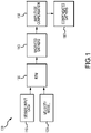
- FIG. 1 is an RTM amplitude recovery flow diagram 100; e.g., in the form of a block diagram depicting process flow for recovering amplitudes in reverse time migration for amplitude versus offset and/or amplitude versus angle analysis. More specifically, FIG. 1 is a block diagram depicting process flow for recovering amplitudes in reverse time migration for amplitude versus offset and/or amplitude versus angle analysis.
- seismic input data (step 110) and a velocity model (step 120) are used for reverse time migration (step 130), generating migrated gathers (step 140).
- Amplitude compensation (step 150) is performed to generate compensated gathers (step 160), for use in imaging the subsurface structure.
- FIG. 1 depicts the flow for recovering the amplitudes in RTM for AVO/AVA analysis.
- Seismic traces (step 110) and a velocity model (step 120) are the inputs to RTM (step 130).
- the velocity model used for migration is a relatively smooth model that may contain high reflectivity contrasts such as a water bottom interface and salt-sediment boundaries and can incorporate anisotropy.
- the output domain of the migrated gathers (step 140) could be in offset, sub-surface offset, time shift or angle gather. Amplitudes are then corrected post-migration (steps 150, 160).
- Migration of the seismic data builds an image of the Earth's interior surface from recorded field data, by repositioning the data to their "true" geological position in the subsurface; e.g., using numerical approximations from a wave or ray-based model or description of the propagation of sound waves in the subsurface.
- the migration can be performed in a number of stages, for both ray and wave-extrapolation based methods.
- the final stage of the migration process is that which forms the image, via an imaging condition.
- FIG. 2A is a detail view of an amplitude compensation algorithm or process 200; e.g., in the form of a block diagram illustrating an amplitude compensation algorithm suitable for use with the process flow illustrated in the block diagram of FIG. 1 .
- the amplitude compensation process 200 includes generating or providing one or more of a velocity model (step 120), a reflectivity model (step 210), and source-receiver geometry (step 220), which are used for numeric modeling (step 230), synthetics (step 235), RTM (step 240), and generating synthetic migrated gathers (step 245).
- the reflectivity model (step 210) and synthetic migrated gathers (step 245) used to generate a filter or filter algorithm (step 250).
- the migrated gathers (step 140) are filtered (step 255) to generate amplitude compensated gathers (step 260); e.g., for AVO/AVA processing (step 270) and imaging (step 280).
- FIG. 2A thus describes steps comprised in the amplitude compensation algorithm or process 200.
- synthetic seismograms are computed (step 235) by numeric modeling (step 230), using a process of, based on or akin to the inverse process of migration, sometimes referred to as Born modeling.
- Inputs to the modeling are the same velocity model 120 used for migrating the seismic data in FIG. 1 , an ad hoc reflectivity grid model (step 210) of the same or similar dimensions as the velocity model, and a source-receiver geometry (step 220) matching the geometry of the seismic data in FIG. 1 (step 110).
- the reflectivity model (step 210) is composed of a set of horizontal reflectors that span the space of the output migrated data.
- the computed synthetic seismograms (step 235) contain primary reflections created by the reflectivity model (step 210) with amplitudes that are solely or substantially due to transmission effects, but in contrast to the real seismic traces they may lack amplitude variations with offset introduced by elastic property contrasts of the real subsurface geology.
- the synthetic seismograms are then migrated with RTM (step 240), resulting in gathers (step 245) in the same domain of the migrated seismic traces of FIG. 1 .
- the amplitudes of the migrated synthetic gathers may not match the amplitudes of the input ad hoc reflectivity model (step 210). This difference is used in the second set of steps of process 200 in FIG. 2A to estimate a scalar correction filter (step 250) that compensates for the distortion at each reflectivity horizon level.
- the scalar filter (step 250) is then interpolated in the depth axis to produce a gridded volume of scalar filters (step 255) that are applied to the migrated seismic traces of FIG. 1 (step 140) to produce amplitude compensated gathers (step 260) as indicated in the third set of steps of process 200 in FIG. 2A .
- Suitable amplitude compensated gathers can be generated in a number of forms, e.g., offset gathers or vector offset gathers based on a space-shifted imaging condition, time-shifted gathers, and angle or vector angle gathers based on Poynting vectors (e.g., Poynting vector gathers).
- the amplitude compensated gathers (step 260) can be utilized for Amplitude Versus Offset (AVO) analysis or Amplitude Versus Angle (AVA) analysis, or both (step 270), in order to generate stacked images representative of the subsurface geology (step 280).
- AVO Amplitude Versus Offset
- AVA Amplitude Versus Angle
- one or both of the AVA/AVO (step 270) and stacked imaged (280) processing stees can be performed independently, or in parallel.
- the amplitude compensation process 200 restores amplitudes in depth and offset, subsurface-offset, time shift, angle or any other horizontal spatial axis.
- the compensation is robust given the fact that the migration velocity model (step 120) is often a relatively smooth model.
- image generation (step 280) is improved, provided higher fidelity images of the complex geological structures and other subsurface geology.
- FIG. 2B is a block diagram of a computer seismic imaging system 201 configured to perform seismic data processing, modeling and imaging according to methods 100 and 200 of FIGS. 1 and 2A .
- a suitable seismic imaging system 201 can include a computer processor 202 coupled with a combination of volatile and non-volatile (non-transitory) memory 203 for storing seismic data 205 and code 205, which can be executed on the processor 203 to perform data processing and imaging according to methods 100 and 200.
- a visual display or graphical user interface (GUI) 206 is provided for outputting the processed seismic data; e.g., in the form of seismic images representative of the subsurface geology.
- GUI graphical user interface
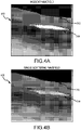
- FIG. 3A is a schematic illustration of a representative smooth velocity field or velocity model 310; e.g., a background velocity.
- FIG. 3B is a schematic illustration of a reflectivity R or reflectivity model 320; e.g., a secondary source reflectivity overlaying the background velocity.
- depth is plotted on the vertical axis, with xline position on the horizontal axis.
- the initial model may typically have a smooth velocity field
- a detailed interpretation of the water bottom (for marine data) and surface topography (for land data) can be incorporated; e.g., including relevant bottom features and subsurface structures 312, 314, etc.
- the information used to build the initial model may come from time-domain information such as picked time horizons, stacking velocity fields, interval velocities, vertical compaction gradients or well information, and anisotropic parameter estimates if available.
- FIG. 4A is a schematic illustration of a velocity model at which the incident wavefield 410 propagates; e.g., where the reflectivity 320 scatters the incident wavefield 410.
- FIG. 4B is a schematic illustration of the velocity model and reflectivity that scatters the wavefield; e.g., a single scattering wavefield that does not interact with the reflectivity 320.
- depth is plotted on the vertical axis, with xline position on the horizontal axis.
- the recorded signal is the upward propagating wavefield as measured at the receivers; e.g., based on the Earth's reflectivity response and the background model, convolved with the downward going source wavelet. There may be velocity contrast at the layer boundaries.
- the inputs to the Born modeling process 200 can include a smooth velocity field 310 ( FIG. 3A ); e.g., suitable for use as a velocity model (step 120), and a reflectivity 320 ( FIG. 3B ) that scatters an incident wavefield 410 ( FIG. 4A ), which may be suitable for use as a reflectivity model (step 210).
- the scattered wavefield 420 ( FIG. 4B ) can be independent of and not interact with the reflectivity; e.g., depending on embodiment, internal multiples are not necessarily modeled, and no internal multiples may be modeled.
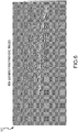
- FIG. 5 is a representative synthetic CSG plot 510.
- CSG plot 510 may be representative of computed synthetic seismograms according to step 235 of method 200 as shown in FIG. 2 , either alone or in combination with any one or more additional process steps performed to produce amplitude compensated gathers, as disclosed herein.
- the nature of the problem can thus be outlined with synthetic data derived from the model; e.g., with a smooth background velocity field.
- the appearance of the final migrated image will depend, inter alia, on the interplay of AVO and migration velocity.
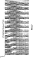
- FIG. 6 is a plot of representative RTM surface offset gathers 610 from synthetic traces.
- depth is plotted on the vertical axis, with xline/offset on the horizontal axis.
- RTM gathers 610 from synthetic traces may be representative of synthetic migrated gathers according to step 245 of method 200 as shown in FIG. 2 , either alone or in combination with any one or more additional process steps performed to produce amplitude compensated gathers, as disclosed herein.
- FIG. 7 is a plot of representative RTM amplitude compensation surface offset scalar filters 710. Depth is plotted on the vertical axis, with xline/offset on the horizontal axis.
- RTM scalar filter data 710 may be representative of scalar correction filter data that compensate for distortion at each reflectivity horizon level according to step 250 of method 200 as shown in FIG. 2 , or such data interpolated in the depth axis to produce a gridded volume of scalar filters applied to the migrated seismic traces according to step 255, either alone or in combination with any one or more additional process steps performed to produce amplitude compensated gathers, as disclosed herein.
- FIG. 8 is a plot of representative input RTM surface offset gathers 810, before amplitude compensation correction. Depth is plotted on the vertical axis, with xline/offset on the horizontal axis.
- RTM gathers 810 may be representative of migrated seismic traces according to step 140 of method 100 as shown in FIG. 1 , before a gridded volume of scalar filters are applied to the migrated seismic traces according to step 255 of process 200, either alone or in combination with any one or more additional process steps performed to produce amplitude compensated gathers, as disclosed herein.
- FIG. 9 is a plot of representative RTM surface offset gathers 910, after amplitude compensation correction. Depth is plotted on the vertical axis, with xline/offset on the horizontal axis.
- RTM gathers 910 may be representative of migrated seismic traces according to step 140 of method 100 as shown in FIG. 1 , after a gridded volume of scalar filters are applied to the migrated seismic traces according to step 255 of process 200, either alone or in combination with any one or more additional process steps performed to produce amplitude compensated gathers, as disclosed herein.
- Correcting the amplitude of the recorded signal can help compensate for variation in source output and receiver coupling, and provide a more stable correction in the presence of noise.
- Real data examples can also show that compensation enhances the higher-frequency components in complex geological structures.
- These amplitude compensation techniques can also be used in combination with other seismic imaging procedures to improve resolution of the subsurface structures, including, but not limited to, those disclosed in U.S. Patent Application Serial No. 15/375,471 , SYSTEM AND
- a method of seismic imaging comprising the steps of: obtaining seismic data acquired by a seismic receiver comprising at least one of a geophone and a hydrophone deployed to a seismic medium, the seismic data responsive to seismic energy generated by at least one seismic source and propagating through the seismic medium by reflection from a subsurface geology; and obtaining a set of seismic traces based on the acquired seismic data, each of the seismic traces including one or more samples of the seismic energy.
- the method also includes the additional steps of: generating a set of migrated gathers by performing reverse time migration on the seismic traces using a velocity model of the seismic energy propagating through the seismic medium, wherein the migrated gathers have amplitudes based at least in part on the reverse time migration and the velocity model; generating synthetic migrated seismograms based on the velocity model and a source-receiver geometry representative of the at least one source and seismic receiver; generating a filter based on the synthetic migrated gathers; generating amplitude compensated gathers from the migrated gathers, wherein the filter is applied to correct the amplitudes; and generating a seismic image of the subsurface geology, based on the amplitude compensated migrated gathers.
- the method may further comprise amplitude versus offset or amplitude versus angle analysis of the amplitude compensated gathers, or both, where the seismic image is based at least in part on the analysis.
- the method may further comprise numeric modeling of synthetic seismograms based on the velocity model and the source-receiver geometry and migrating the synthetic seismograms with reverse time migration to provide the synthetic migrated gathers in a same output domain as the migrated gathers.
- the output domain may be at least one of offset, sub-surface offset, time shift, or angle gather.
- the numeric modeling may be based on a reflectivity model of the seismic medium, the reflectivity model having same dimensions as the velocity model and being representative of a set of reflectors that span a space of the migrated gather, wherein the source-receiver geometry matches a geometry of the seismic traces.
- the synthetic seismograms are representative of primary reflections based on the reflectivity model with amplitudes due to transmission effects, and wherein the synthetic seismograms lack amplitude variations with offset introduced by elastic property contrasts of the subsurface geology.
- generating the filter comprises estimating a scalar correction filter based on a difference in amplitudes of the migrated gathers and amplitudes of the reflectivity model, wherein the scalar correction filter compensates for the distortion at each reflectivity horizon level in the reflectivity model.
- the method may further comprise interpolating the scalar correction filter in a depth axis to produce a gridded volume of scalar filters, wherein applying the filter comprises applying the scalar filters to the migrated gathers to provide the amplitude compensated gathers.
- the velocity model may represent the background velocity and the amplitude may comprise distortion due at least in part to the reverse time migration, and correcting the amplitudes may comprise reducing the distortion.
- the velocity model may be anisotropic.
- a method of geophysical exploration comprising: detecting, by a seismic receiver, seismic energy in a seismic medium through which a seismic wavefield propagates; obtaining a set of seismic traces based on the detected seismic energy, wherein the seismic traces are responsive to the seismic wavefield being reflected from a subsurface geology; reverse time migrating the seismic traces to generate migrated gathers based on a velocity model of the seismic medium, wherein the migrated gathers have amplitude distortion due to the reverse time migration; numeric modeling of synthetic traces based on the velocity model and a source-receiver geometry matching a geometry of the seismic traces; reverse time migrating the synthetic gathers to generate synthetic migrated gathers; generating amplitude compensated gathers from the migrated gathers, wherein a filter based on the synthetic migrated gathers is applied to at least partially correct the amplitude distortion; and generating a seismic image of the subsurface geology by performing one or both of amplitude versus offset and amplitude versus angle analysis of the
- the velocity model may be anisotropic and may contain reflectivity contrasts including a water bottom interface.
- the method may further comprise performing the reverse time migrating of the synthetic seismograms to generate the synthetic migrated gathers in a same output domain as the migrated gathers, wherein the output domain is at least one of offset, sub-surface offset, time shift, or angle gather.
- the method may generate the filter based on a difference in amplitudes of the synthetic migrated gathers and a reflectivity model of the seismic medium, the reflectivity model representing a set of reflectors that span a space of the migrated gathers.
- the method may further comprise estimating a scalar correction filter based on the difference in amplitudes of the synthetic migrated gathers and the reflectivity model, wherein the scalar correction filter at least partially compensates for the amplitude distortion.
- the method may comprise interpolating the scalar correction filter in a depth axis and optionally in the offset or angle axis to produce a gridded volume of scalar filters and applying the scalar filters to the migrated gathers to generate the amplitude compensated gathers.
- the numeric modeling may be based on the reflectivity model, with the reflectivity model having the same dimensions as the velocity model such that the synthetic traces are representative of primary reflections created by the reflectivity model.
- the synthetic traces may have amplitudes representative of transmission effects and lack amplitude variations with offset introduced by elastic property contrasts of the subsurface geology.
- a system comprising a computer processor and non-transitory memory for storing program code executable on the computer processor to perform a method of seismic imaging, the method comprising: obtaining a set of seismic traces based on seismic energy detected by a seismic receiver deployed to a seismic medium through which a seismic wavefield propagates, wherein the seismic traces are responsive to the seismic wavefield reflected from a subsurface geology; reverse time migrating the seismic traces to generate migrated gathers based on a velocity and a reflectivity model of the seismic medium, wherein the migrated gathers have amplitude distortion due to the reverse time migration; numeric modeling of synthetic traces based on the velocity model, a reflectivity model of the seismic medium having a same dimension as the velocity model, and a source-receiver geometry matching a geometry of the seismic traces; reverse time migrating the synthetic gathers to generate synthetic migrated gathers; generating a filter based on a difference in amplitudes of the synthetic migrated gathers and the reflectivity model, the
- generating the filter may comprise: estimating a scalar correction filter based on the difference in amplitudes of the synthetic migrated gathers and the reflectivity model, wherein the scalar correction filter at least partially compensates for the amplitude distortion; and interpolating the scalar correction filter in a depth axis, or in the depth axis and in the offset or angle axis, in order to produce a gridded volume of scalar filters; wherein applying the scalar filters are applied to the migrated gathers to generate the amplitude compensated gathers.
- Methods for geophysical exploration in a seismic survey area, comprising one or more steps of: acquiring, by a seismic receiver comprising at least one of a geophone and a hydrophone, seismic data responsive to seismic energy propagating through at least one seismic medium in the form of a seismic wavefield; obtaining a set of seismic traces based on the acquired seismic data, each of the seismic traces including one or more detected samples of the seismic wavefield.
- RTM reverse time migration
- the amplitudes of the migrated gathers can be corrected by computing synthetic seismograms to provide compensated gathers, performing amplitude versus offset and/or amplitude versus angle analysis of the compensated gathers, and generating a seismic image of subsurface structures in the survey area, based on the amplitude versus offset and/or amplitude versus angle analysis.
- the seismic model represents background velocity
- the amplitude may comprise distortion due at least in part to the RTM; e.g., where correcting the amplitudes comprises reducing the distortion.
- the amplitudes may be sufficiently corrected such that the resulting compensated gathers can be utilized for amplitude versus offset and/or amplitude versus angle analysis.
- the velocity model contains reflectivity contrasts, including a water bottom interface and salt-sediment boundaries.
- the velocity model may be anisotropic.
- the output domain for the migrated gathers is at least one of offset, sub-surface offset, time shift, or angle gather.
- the method may work irrespective of the angle transformation.
- computing synthetic seismograms comprises Born modeling.
- the velocity model used as input for RTM can also be used as input for correcting the amplitudes.
- inputs for correcting the amplitude further include a reflectivity grid model of the same or similar dimensions as the velocity model, and a source-receiver geometry that matches the geometry of the seismic traces.
- the reflectivity model may comprise a set of horizontal reflectors that span the space of the output migrated data.
- Some examples include estimating a scalar correction filter based on a difference in amplitudes of the migrated gathers and the amplitudes of the input reflectivity model; e.g., where the scalar correction filter compensates for the distortion at each reflectivity horizon level.
- the method can also include interpolating the scalar filter in the depth axis and optionally in the offset or angle axis to produce a gridded volume of scalar filters, which are applied to the migrated gathers to provide compensated gathers.
- the computed synthetic seismograms can contain primary reflections created by the reflectivity model with amplitudes that are due solely to transmission effects, or that lack amplitude variations with offset introduced by elastic property contrasts of the real subsurface geology.
- the method includes migrating the synthetic seismograms with RTM to provide gathers in the same domain as the migrated gathers.
- the amplitude compensation can restore amplitudes in depth and offset, subsurface-offset, time shift, and angle.
- a computer system can be provided with memory in communication with a computer processor, which is configured to execute a method according to any of the examples herein.
- a method of geophysical exploration can include one or more steps of detecting, by a seismic receiver, seismic energy in the form of acoustic waves or other disturbances of at least one medium through which a seismic wavefield propagates; and obtaining a set of seismic traces based on the detected seismic energy, each trace including one or more detected samples of the seismic energy. Further steps can include generating or receiving a velocity model, and, based on the measured seismic traces and the velocity model, carrying out reverse time migration (RTM) to provide migrated gathers; e.g., where the migrated gathers may have amplitude distortions due to the RTM.
- RTM reverse time migration
- the distorted amplitudes of the migrated gathers can be corrected by computing synthetic seismograms to provide compensated gathers, where the amplitudes are sufficiently corrected to that the resulting compensated gathers can be utilized for amplitude versus offset and/or amplitude versus angle analysis.
- the velocity model contains reflectivity contrasts, including a water bottom interface and salt-sediment boundaries.
- the velocity model may be anisotropic.
- the output domain for the migrated gathers is at least one of offset, sub-surface offset, time shift, or angle gather.
- the method can work irrespective of the angle transformation.
Landscapes
- Engineering & Computer Science (AREA)
- Remote Sensing (AREA)
- Physics & Mathematics (AREA)
- Life Sciences & Earth Sciences (AREA)
- Acoustics & Sound (AREA)
- Environmental & Geological Engineering (AREA)
- Geology (AREA)
- General Life Sciences & Earth Sciences (AREA)
- General Physics & Mathematics (AREA)
- Geophysics (AREA)
- Geophysics And Detection Of Objects (AREA)
Claims (13)
- Verfahren zur seismischen Abbildung, das Verfahren umfassend folgende Schritte:Erhalten von seismischen Daten (110), welche von einem seismischen Empfänger, welcher zumindest ein Geophon und/oder ein Hydrophon, welches in ein seismisches Medium eingebracht ist, umfasst, erfasst werden, wobei die seismischen Daten (110) empfindlich gegenüber seismischer Energie sind, welche von zumindest einer seismischen Quelle erzeugt wird und welche sich über Reflektion von einer Untergrundgeologie durch das seismische Medium ausbreitet;Erhalten eines Satzes an seismischen Spuren, welche auf den erfassten seismischen Daten (110) basieren, wobei jeder der seismischen Spuren eine oder mehrere Proben der seismischen Energie beinhaltet;Erzeugen eines Satzes an migrierten Datensätzen (140) durch Durchführung von Zeitverschiebung (130) der seismischen Spuren unter Verwendung eines Geschwindigkeitsmodells (120) der sich durch das seismische Medium ausbreitenden seismischen Energie, wobei die migrierten Datensätze (140) Amplituden aufweisen, welche zumindest teilweise auf der Zeitverschiebung (130) und dem Geschwindigkeitsmodell (120) basieren;Erzeugen von amplitudenkompensierten Datensätzen (260) aus den migrierten Datensätzen (140);
undErzeugen einer seismischen Abbildung (280) der Untergrundgeologie basierend auf den amplitudenkompensierten Datensätzen (260); dadurch gekennzeichnet, dass das Verfahren weiterhin die folgenden Schritte umfasst:Erzeugen künstlicher migrierter Datensätze (245) basierend auf dem Geschwindigkeitsmodell (120) und einer Quellenempfängergeometrie (220), welche repräsentativ für die zumindest eine Quelle und den seismischen Empfänger ist; undErzeugen eines Filters (250) basierend auf den künstlichen migrierten Datensätzen (245) und auf ein Reflektionsmodell (210), wobei der Filter (250) auf die migrierten Datensätze (140) angewandt wird um die Amplituden zu korrigieren. - Verfahren nach Anspruch 1, weiterhin umfassend eine Analyse von Amplitude gegen Versatz und/oder eine Analyse von Amplitude gegen Winkel der amplitudenkompensierten Datensätze, wobei das seismische Abbild zumindest teilweise auf der Analyse basiert.
- Verfahren nach Anspruch 1, weiterhin umfassend numerische Modellierung (230) von künstlichen Seismogrammen basierend auf dem Geschwindigkeitsmodell (120) und auf der Quellenempfängergeometrie (220) und Migrieren der künstlichen Seismogramme durch Zeitverschiebung (240) zur Verfügungstellung der künstlichen migrierten Datensätze (245) in einem selben Ausgangsbereich wie die migrierten Datensätze (140).
- Verfahren nach Anspruch 3, wobei der Ausgangsbereich zumindest einer der folgenden ist: Versatz, Untergrundversatz, Zeitverschiebung oder Winkelerfassung.
- Verfahren nach Anspruch 3, wobei die numerische Modellierung (230) auf dem Reflektionsmodell (210) des seismischen Mediums basiert, wobei das Reflektionsmodell (210) dieselben Dimensionen wie das Geschwindigkeitsmodell (120) aufweist und wobei das Reflektionsmodell (210) einen Satz an Reflektoren repräsentiert, welche einen Raum des migrierten Datensatzes (140) aufspannen, wobei die Quellenempfängergeometrie (220) mit einer Geometrie der seismischen Spuren übereinstimmt.
- Verfahren nach Anspruch 5, wobei die künstlichen Seismogramme repräsentativ für Primärreflektionen sind, welche auf dem Reflektionsmodell (210) mit Amplituden aufgrund von Transmissionseffekten basieren, und wobei den künstlichen Seismogramme Amplitudenvariationen mit Versatz fehlen, welche durch elastische Eigenschaftskontraste der Untergrundgeologie eingeführt werden.
- Verfahren nach Anspruch 5, wobei Erzeugen des Filters (250) Schätzen eines skalaren Korrekturfilters basierend auf einer Differenz von Amplituden der künstlich migrierten Datensätze (245) und Amplituden des Reflektionsmodells (210) umfasst, wobei der skalare Korrekturfilter die Verzerrung an jedem Reflektionshorizontniveau in dem Reflektionsmodell (210) kompensiert.
- Verfahren nach Anspruch 7, weiterhin umfassend Interpolieren des skalaren Korrekturfilters in einer oder mehrere von einer Tiefenachse und einer Versatz- oder Winkelachse, um ein gerastertes Volumen von Skalarfiltern zu produzieren, wobei die Anwendung des Filters das Anwenden des Skalarfilters auf den migrierten Datensatz umfasst, um den amplitudenkompensierten Datensatz bereitzustellen.
- Verfahren nach Anspruch 1, wobei das Geschwindigkeitsmodell (120) Untergrundgeschwindigkeit repräsentiert und die Amplitude Verzerrung aufweist, welche zumindest teilweise auf die umgekehrte Zeitverschiebung (130) zurückzuführen ist, und wobei die Korrektur der Amplituden die Verringerung der Verzerrung umfasst.
- Verfahren nach Anspruch 9, wobei das Geschwindigkeitsmodell (120) Reflektionskontraste umfasst, welche eine Wasser-Boden-Schnittstelle beinhalten, wobei das Geschwindigkeitsmodell (120) anisotrop ist.
- Verfahren nach einem der Ansprüche 1 bis 10, wobei das seismische Abbild zur Durchführung von geophysikalischen Untersuchungen verwendet wird.
- System umfassend einen Computerprozessor und nicht flüchtigen Speicher zur Speicherung von Programmcode, welcher durch den Computerprozessor ausführbar ist um ein Verfahren zur seismischen Abbildung auszuführen, das Verfahren umfassend die folgenden Schritte:Erhalten eines Satzes an seismischen Spuren (110) basierend auf seismischer Energie, welche durch einen seismischen Empfänger erfasst wird, welcher in ein seismisches Medium eingebracht ist, durch welches sich ein seismisches Wellenfeld ausbreitet, wobei die seismischen Spuren empfindlich für das von der Untergrundgeologie reflektierte seismische Wellenfeld sind;umgekehrte Zeitverschiebung (130) der seismischen Spuren zur Erzeugung von migrierten Datensätzen (140) basierend auf einem Geschwindigkeitsmodell (120) des seismischen Mediums, wobei die migrierten Datensätze (140) Amplitudenverzerrung durch die umgekehrte Zeitverschiebung (240) aufweisen;numerische Modellierung (230) von künstlichen Spuren basierend auf dem Geschwindigkeitsmodell (210), einem Reflektionsmodell (210) des seismischen Mediums mit einer gleichen Dimension des Geschwindigkeitsmodells (120), und einer Quellenempfängergeometrie (220), welche mit einer Geometrie der seismischen Spuren übereinstimmt;Erzeugen von amplitudenkompensierten Datensätzen (260) aus den migrierten Datensätzen (140);
undErzeugen eines seismischen Abbildes (280) der Untergrundgeologie durch Ausführen einer Analyse von Amplitude gegen Versatz und/oder einer Analyse von Amplitude gegen Winkel der amplitudenkompensierten Datensätze (260);umgekehrte Zeitverschiebung (240) der künstlichen Spuren zur Erzeugung von künstlichen migrierten Datensätzen (245); undErzeugen eines Filters (250) basierend auf einer Differenz von Amplituden der künstlichen migrierten Datensätze (245) und des Reflektionsmodells (210), wobei das Reflektionsmodell (210) einen Satz an Reflektoren, welche einen Raum der migrierten Datensätze (140) aufspannen, repräsentiert, wobei der Filter (250) auf die migrierten Datensätze (140) angewandt wird um zumindest teilweise die Amplitudenverzerrung zu korrigieren. - System nach Anspruch 12, wobei Erzeugen des Filters (250) folgendes umfasst:Schätzen eines skalaren Korrekturfilters basierend auf der Differenz von Amplituden der künstlichen migrierten Datensätze (245) und Amplituden des Reflektionsmodells (210), wobei die skalaren Korrekturfilter zumindest teilweise die Amplitudenverzerrung kompensieren; undInterpolieren des skalaren Korrekturfilters in eine oder mehrere von einer Tiefenachse und einer Versatz- oder Winkelachse um ein gerastertes Volumen von Skalarfiltern zu produzieren,wobei das Anwenden der Skalarfilter auf die migrierten Datensätze (140) angewandt wird um die amplitudenkompensierten Datensätze (260) zu erzeugen.
Applications Claiming Priority (2)
| Application Number | Priority Date | Filing Date | Title |
|---|---|---|---|
| US201762477237P | 2017-03-27 | 2017-03-27 | |
| PCT/US2018/024594 WO2018183346A1 (en) | 2017-03-27 | 2018-03-27 | Amplitude compensation of reverse time migration (rtm) gathers for avo/ava analysis |
Publications (2)
| Publication Number | Publication Date |
|---|---|
| EP3602136A1 EP3602136A1 (de) | 2020-02-05 |
| EP3602136B1 true EP3602136B1 (de) | 2022-05-18 |
Family
ID=61972622
Family Applications (1)
| Application Number | Title | Priority Date | Filing Date |
|---|---|---|---|
| EP18718058.3A Active EP3602136B1 (de) | 2017-03-27 | 2018-03-27 | Amplitudenkompensation von sammlungen von reverse-time-migration (rtm) zur avo/ava-analyse |
Country Status (4)
| Country | Link |
|---|---|
| US (1) | US10884148B2 (de) |
| EP (1) | EP3602136B1 (de) |
| AU (1) | AU2018246210A1 (de) |
| WO (1) | WO2018183346A1 (de) |
Families Citing this family (15)
| Publication number | Priority date | Publication date | Assignee | Title |
|---|---|---|---|---|
| WO2019060249A1 (en) * | 2017-09-21 | 2019-03-28 | The Regents Of The University Of California | TENSEUR RECONSTRUCTION OF MOMENT |
| US10670755B2 (en) * | 2018-04-02 | 2020-06-02 | Chevron U.S.A. Inc. | Systems and methods for refining estimated effects of parameters on amplitudes |
| WO2019234469A1 (en) * | 2018-06-08 | 2019-12-12 | Total Sa | Method for generating an image of a subsurface of an area of interest from seismic data |
| WO2020122915A1 (en) * | 2018-12-13 | 2020-06-18 | Halliburton Energy Services, Inc. | Seismic multiples mitigation in borehole seismic data using inversion |
| US11346967B2 (en) * | 2019-09-10 | 2022-05-31 | Advanced Geophysical Technology Inc. | Systems and methods for providing amplitude versus offset compliant migration gathers |
| CN112666601B (zh) * | 2019-10-15 | 2024-03-22 | 中国石油化工股份有限公司 | 一种地震数据振幅拟合有效时窗的方法及其系统 |
| CN110673212B (zh) * | 2019-10-25 | 2021-06-18 | 北京多分量地震技术研究院 | 一种模型约束的薄层多波ava联合反演方法 |
| US11914101B2 (en) | 2020-01-31 | 2024-02-27 | ExxonMobil Technology and Engineering Company | Method for partitioning a search direction when using least squares reverse time migration |
| CN111239804B (zh) * | 2020-02-12 | 2021-07-02 | 中国石油大学(华东) | 一种弹性能量逆时偏移成像方法、装置、设备及系统 |
| US20210255346A1 (en) * | 2020-02-19 | 2021-08-19 | Chevron U.S.A. Inc. | System and Method for Seismic Imaging with Amplitude Recovery |
| US12060781B2 (en) | 2020-02-20 | 2024-08-13 | ExxonMobil Technology and Engineering Company | Method for generating initial models for least squares migration using deep neural networks |
| CN113589379B (zh) * | 2020-04-30 | 2023-10-20 | 中国石油化工股份有限公司 | 叠前道集保真性振幅补偿优化方法 |
| CN112782767B (zh) * | 2020-12-26 | 2022-07-01 | 中油奥博(成都)科技有限公司 | 一种das采集vsp变偏移距波场径向补偿方法与装置 |
| CN116009093A (zh) * | 2021-10-21 | 2023-04-25 | 中国石油化工股份有限公司 | 一种真地表面偏移方法、电子设备、介质及装置 |
| US12204060B2 (en) * | 2021-12-10 | 2025-01-21 | China Petroleum & Chemical Corporation | Full-wavefield angle gather for high-contrast inter thin-bed models |
Family Cites Families (13)
| Publication number | Priority date | Publication date | Assignee | Title |
|---|---|---|---|---|
| WO2010085493A1 (en) * | 2009-01-20 | 2010-07-29 | Spectraseis Ag | Time reverse imaging operators for source location |
| US9658353B2 (en) * | 2010-06-17 | 2017-05-23 | Westerngeco L.L.C. | Regulating coherent boundary reflections during generation of a modeled wavefield |
| US9625593B2 (en) * | 2011-04-26 | 2017-04-18 | Exxonmobil Upstream Research Company | Seismic data processing |
| EP2724181B1 (de) | 2011-06-24 | 2020-08-19 | ION Geophysical Corporation | Verfahren und vorrichtung für seismische rauschverminderung |
| US20130201792A1 (en) | 2012-02-03 | 2013-08-08 | Ion Geophysical Corporation | Method and apparatus for processing seismic data |
| US10061046B2 (en) | 2012-02-06 | 2018-08-28 | Ion Geophysical Corporation | Integrated passive and active seismic surveying using multiple arrays |
| US9405028B2 (en) | 2013-02-22 | 2016-08-02 | Ion Geophysical Corporation | Method and apparatus for multi-component datuming |
| WO2014165219A2 (en) | 2013-03-12 | 2014-10-09 | Ion Geophysical Corporation | Sensor system of buried seismic array |
| US9766357B2 (en) * | 2013-11-05 | 2017-09-19 | Exxonmobil Upstream Research Company | Seismic image dip decomposition estimation and recomposition |
| US10185046B2 (en) * | 2014-06-09 | 2019-01-22 | Exxonmobil Upstream Research Company | Method for temporal dispersion correction for seismic simulation, RTM and FWI |
| US9784867B2 (en) * | 2015-04-01 | 2017-10-10 | Schlumberger Technology Corporation | Seismic data processing |
| US10295683B2 (en) * | 2016-01-05 | 2019-05-21 | Schlumberger Technology Corporation | Amplitude inversion on partitioned depth image gathers using point spread functions |
| US10677949B2 (en) * | 2017-01-05 | 2020-06-09 | China Petroleum & Chemical Corporation | Anisotropy matching filtering for attenuation of seismic migration artifacts |
-
2018
- 2018-03-27 EP EP18718058.3A patent/EP3602136B1/de active Active
- 2018-03-27 AU AU2018246210A patent/AU2018246210A1/en not_active Abandoned
- 2018-03-27 WO PCT/US2018/024594 patent/WO2018183346A1/en not_active Ceased
- 2018-03-27 US US15/937,407 patent/US10884148B2/en active Active
Also Published As
| Publication number | Publication date |
|---|---|
| EP3602136A1 (de) | 2020-02-05 |
| WO2018183346A1 (en) | 2018-10-04 |
| US20180275302A1 (en) | 2018-09-27 |
| US10884148B2 (en) | 2021-01-05 |
| AU2018246210A1 (en) | 2019-10-31 |
Similar Documents
| Publication | Publication Date | Title |
|---|---|---|
| EP3602136B1 (de) | Amplitudenkompensation von sammlungen von reverse-time-migration (rtm) zur avo/ava-analyse | |
| US11487036B2 (en) | Reflection full waveform inversion methods with density and velocity models updated separately | |
| US10928534B2 (en) | Method of, and apparatus for, full waveform inversion | |
| AU2020363643B2 (en) | Determining properties of a subterranean formation using an acoustic wave equation with a reflectivity parameterization | |
| US8352190B2 (en) | Method for analyzing multiple geophysical data sets | |
| AU2010201504B2 (en) | Method for calculation of seismic attributes from seismic signals | |
| US8937848B2 (en) | Methods and systems to eliminate undesirable variations in time-lapse seismic surveys | |
| EP3094993B1 (de) | Vorrichtung und verfahren zum deghosting seismischer daten anhand einer geringen tau-p-inversion | |
| US11550072B2 (en) | Method and apparatus for deblending seismic data using a non-blended dataset | |
| US20130289879A1 (en) | Process for characterising the evolution of a reservoir | |
| US11029432B2 (en) | De-aliased source separation method | |
| US20220373703A1 (en) | Methods and systems for generating an image of a subterranean formation based on low frequency reconstructed seismic data | |
| US10012747B2 (en) | Device and method for joint 3-dimensional deghosting of multiple vintages | |
| US10107928B2 (en) | Method and device for removal of water bottom and/or geology from near-field hydrophone data | |
| Liu et al. | Time-lapse full-waveform inversion for elastic TTI media | |
| Tylor-Jones et al. | Processing Essentials | |
| Yu et al. | High-fidelity numerical simulation of ocean-bottom node 4C seismic data using the acoustic-elastic coupling equation | |
| NO20231372A1 (en) | Seismic data processing using a down-going annihilation operator | |
| Li et al. | Wave-equation Qs | |
| Al-Saleh | Application of prestack plane wave Kirchhoff depth migration of obc data |
Legal Events
| Date | Code | Title | Description |
|---|---|---|---|
| STAA | Information on the status of an ep patent application or granted ep patent |
Free format text: STATUS: UNKNOWN |
|
| STAA | Information on the status of an ep patent application or granted ep patent |
Free format text: STATUS: THE INTERNATIONAL PUBLICATION HAS BEEN MADE |
|
| PUAI | Public reference made under article 153(3) epc to a published international application that has entered the european phase |
Free format text: ORIGINAL CODE: 0009012 |
|
| STAA | Information on the status of an ep patent application or granted ep patent |
Free format text: STATUS: REQUEST FOR EXAMINATION WAS MADE |
|
| 17P | Request for examination filed |
Effective date: 20191025 |
|
| AK | Designated contracting states |
Kind code of ref document: A1 Designated state(s): AL AT BE BG CH CY CZ DE DK EE ES FI FR GB GR HR HU IE IS IT LI LT LU LV MC MK MT NL NO PL PT RO RS SE SI SK SM TR |
|
| AX | Request for extension of the european patent |
Extension state: BA ME |
|
| DAV | Request for validation of the european patent (deleted) | ||
| DAX | Request for extension of the european patent (deleted) | ||
| STAA | Information on the status of an ep patent application or granted ep patent |
Free format text: STATUS: EXAMINATION IS IN PROGRESS |
|
| 17Q | First examination report despatched |
Effective date: 20210715 |
|
| GRAP | Despatch of communication of intention to grant a patent |
Free format text: ORIGINAL CODE: EPIDOSNIGR1 |
|
| STAA | Information on the status of an ep patent application or granted ep patent |
Free format text: STATUS: GRANT OF PATENT IS INTENDED |
|
| INTG | Intention to grant announced |
Effective date: 20211201 |
|
| GRAS | Grant fee paid |
Free format text: ORIGINAL CODE: EPIDOSNIGR3 |
|
| GRAA | (expected) grant |
Free format text: ORIGINAL CODE: 0009210 |
|
| STAA | Information on the status of an ep patent application or granted ep patent |
Free format text: STATUS: THE PATENT HAS BEEN GRANTED |
|
| AK | Designated contracting states |
Kind code of ref document: B1 Designated state(s): AL AT BE BG CH CY CZ DE DK EE ES FI FR GB GR HR HU IE IS IT LI LT LU LV MC MK MT NL NO PL PT RO RS SE SI SK SM TR |
|
| REG | Reference to a national code |
Ref country code: GB Ref legal event code: FG4D |
|
| REG | Reference to a national code |
Ref country code: CH Ref legal event code: EP |
|
| REG | Reference to a national code |
Ref country code: IE Ref legal event code: FG4D |
|
| REG | Reference to a national code |
Ref country code: DE Ref legal event code: R096 Ref document number: 602018035738 Country of ref document: DE |
|
| REG | Reference to a national code |
Ref country code: AT Ref legal event code: REF Ref document number: 1493481 Country of ref document: AT Kind code of ref document: T Effective date: 20220615 |
|
| REG | Reference to a national code |
Ref country code: LT Ref legal event code: MG9D |
|
| REG | Reference to a national code |
Ref country code: NL Ref legal event code: MP Effective date: 20220518 |
|
| REG | Reference to a national code |
Ref country code: NO Ref legal event code: T2 Effective date: 20220518 |
|
| REG | Reference to a national code |
Ref country code: AT Ref legal event code: MK05 Ref document number: 1493481 Country of ref document: AT Kind code of ref document: T Effective date: 20220518 |
|
| PG25 | Lapsed in a contracting state [announced via postgrant information from national office to epo] |
Ref country code: SE Free format text: LAPSE BECAUSE OF FAILURE TO SUBMIT A TRANSLATION OF THE DESCRIPTION OR TO PAY THE FEE WITHIN THE PRESCRIBED TIME-LIMIT Effective date: 20220518 Ref country code: PT Free format text: LAPSE BECAUSE OF FAILURE TO SUBMIT A TRANSLATION OF THE DESCRIPTION OR TO PAY THE FEE WITHIN THE PRESCRIBED TIME-LIMIT Effective date: 20220919 Ref country code: NL Free format text: LAPSE BECAUSE OF FAILURE TO SUBMIT A TRANSLATION OF THE DESCRIPTION OR TO PAY THE FEE WITHIN THE PRESCRIBED TIME-LIMIT Effective date: 20220518 Ref country code: LT Free format text: LAPSE BECAUSE OF FAILURE TO SUBMIT A TRANSLATION OF THE DESCRIPTION OR TO PAY THE FEE WITHIN THE PRESCRIBED TIME-LIMIT Effective date: 20220518 Ref country code: HR Free format text: LAPSE BECAUSE OF FAILURE TO SUBMIT A TRANSLATION OF THE DESCRIPTION OR TO PAY THE FEE WITHIN THE PRESCRIBED TIME-LIMIT Effective date: 20220518 Ref country code: GR Free format text: LAPSE BECAUSE OF FAILURE TO SUBMIT A TRANSLATION OF THE DESCRIPTION OR TO PAY THE FEE WITHIN THE PRESCRIBED TIME-LIMIT Effective date: 20220819 Ref country code: FI Free format text: LAPSE BECAUSE OF FAILURE TO SUBMIT A TRANSLATION OF THE DESCRIPTION OR TO PAY THE FEE WITHIN THE PRESCRIBED TIME-LIMIT Effective date: 20220518 Ref country code: ES Free format text: LAPSE BECAUSE OF FAILURE TO SUBMIT A TRANSLATION OF THE DESCRIPTION OR TO PAY THE FEE WITHIN THE PRESCRIBED TIME-LIMIT Effective date: 20220518 Ref country code: BG Free format text: LAPSE BECAUSE OF FAILURE TO SUBMIT A TRANSLATION OF THE DESCRIPTION OR TO PAY THE FEE WITHIN THE PRESCRIBED TIME-LIMIT Effective date: 20220818 Ref country code: AT Free format text: LAPSE BECAUSE OF FAILURE TO SUBMIT A TRANSLATION OF THE DESCRIPTION OR TO PAY THE FEE WITHIN THE PRESCRIBED TIME-LIMIT Effective date: 20220518 |
|
| PG25 | Lapsed in a contracting state [announced via postgrant information from national office to epo] |
Ref country code: RS Free format text: LAPSE BECAUSE OF FAILURE TO SUBMIT A TRANSLATION OF THE DESCRIPTION OR TO PAY THE FEE WITHIN THE PRESCRIBED TIME-LIMIT Effective date: 20220518 Ref country code: PL Free format text: LAPSE BECAUSE OF FAILURE TO SUBMIT A TRANSLATION OF THE DESCRIPTION OR TO PAY THE FEE WITHIN THE PRESCRIBED TIME-LIMIT Effective date: 20220518 Ref country code: LV Free format text: LAPSE BECAUSE OF FAILURE TO SUBMIT A TRANSLATION OF THE DESCRIPTION OR TO PAY THE FEE WITHIN THE PRESCRIBED TIME-LIMIT Effective date: 20220518 Ref country code: IS Free format text: LAPSE BECAUSE OF FAILURE TO SUBMIT A TRANSLATION OF THE DESCRIPTION OR TO PAY THE FEE WITHIN THE PRESCRIBED TIME-LIMIT Effective date: 20220918 |
|
| REG | Reference to a national code |
Ref country code: GB Ref legal event code: 732E Free format text: REGISTERED BETWEEN 20221124 AND 20221130 |
|
| RAP2 | Party data changed (patent owner data changed or rights of a patent transferred) |
Owner name: TGS-NOPEC GEOPHYSICAL COMPANY |
|
| PG25 | Lapsed in a contracting state [announced via postgrant information from national office to epo] |
Ref country code: SM Free format text: LAPSE BECAUSE OF FAILURE TO SUBMIT A TRANSLATION OF THE DESCRIPTION OR TO PAY THE FEE WITHIN THE PRESCRIBED TIME-LIMIT Effective date: 20220518 Ref country code: SK Free format text: LAPSE BECAUSE OF FAILURE TO SUBMIT A TRANSLATION OF THE DESCRIPTION OR TO PAY THE FEE WITHIN THE PRESCRIBED TIME-LIMIT Effective date: 20220518 Ref country code: RO Free format text: LAPSE BECAUSE OF FAILURE TO SUBMIT A TRANSLATION OF THE DESCRIPTION OR TO PAY THE FEE WITHIN THE PRESCRIBED TIME-LIMIT Effective date: 20220518 Ref country code: EE Free format text: LAPSE BECAUSE OF FAILURE TO SUBMIT A TRANSLATION OF THE DESCRIPTION OR TO PAY THE FEE WITHIN THE PRESCRIBED TIME-LIMIT Effective date: 20220518 Ref country code: DK Free format text: LAPSE BECAUSE OF FAILURE TO SUBMIT A TRANSLATION OF THE DESCRIPTION OR TO PAY THE FEE WITHIN THE PRESCRIBED TIME-LIMIT Effective date: 20220518 Ref country code: CZ Free format text: LAPSE BECAUSE OF FAILURE TO SUBMIT A TRANSLATION OF THE DESCRIPTION OR TO PAY THE FEE WITHIN THE PRESCRIBED TIME-LIMIT Effective date: 20220518 |
|
| REG | Reference to a national code |
Ref country code: DE Ref legal event code: R097 Ref document number: 602018035738 Country of ref document: DE |
|
| PLBE | No opposition filed within time limit |
Free format text: ORIGINAL CODE: 0009261 |
|
| STAA | Information on the status of an ep patent application or granted ep patent |
Free format text: STATUS: NO OPPOSITION FILED WITHIN TIME LIMIT |
|
| PG25 | Lapsed in a contracting state [announced via postgrant information from national office to epo] |
Ref country code: AL Free format text: LAPSE BECAUSE OF FAILURE TO SUBMIT A TRANSLATION OF THE DESCRIPTION OR TO PAY THE FEE WITHIN THE PRESCRIBED TIME-LIMIT Effective date: 20220518 |
|
| 26N | No opposition filed |
Effective date: 20230221 |
|
| REG | Reference to a national code |
Ref country code: NO Ref legal event code: CREP Representative=s name: ZACCO NORWAY AS, POSTBOKS 488, 0213 OSLO, NORGE Ref country code: NO Ref legal event code: CHAD Owner name: TGS-NOPEC GEOPHYSICAL COMPANY, US |
|
| PG25 | Lapsed in a contracting state [announced via postgrant information from national office to epo] |
Ref country code: SI Free format text: LAPSE BECAUSE OF FAILURE TO SUBMIT A TRANSLATION OF THE DESCRIPTION OR TO PAY THE FEE WITHIN THE PRESCRIBED TIME-LIMIT Effective date: 20220518 |
|
| REG | Reference to a national code |
Ref country code: DE Ref legal event code: R119 Ref document number: 602018035738 Country of ref document: DE |
|
| PG25 | Lapsed in a contracting state [announced via postgrant information from national office to epo] |
Ref country code: MC Free format text: LAPSE BECAUSE OF FAILURE TO SUBMIT A TRANSLATION OF THE DESCRIPTION OR TO PAY THE FEE WITHIN THE PRESCRIBED TIME-LIMIT Effective date: 20220518 |
|
| REG | Reference to a national code |
Ref country code: CH Ref legal event code: PL |
|
| REG | Reference to a national code |
Ref country code: BE Ref legal event code: MM Effective date: 20230331 |
|
| PG25 | Lapsed in a contracting state [announced via postgrant information from national office to epo] |
Ref country code: LU Free format text: LAPSE BECAUSE OF NON-PAYMENT OF DUE FEES Effective date: 20230327 |
|
| REG | Reference to a national code |
Ref country code: IE Ref legal event code: MM4A |
|
| PG25 | Lapsed in a contracting state [announced via postgrant information from national office to epo] |
Ref country code: LI Free format text: LAPSE BECAUSE OF NON-PAYMENT OF DUE FEES Effective date: 20230331 Ref country code: IT Free format text: LAPSE BECAUSE OF FAILURE TO SUBMIT A TRANSLATION OF THE DESCRIPTION OR TO PAY THE FEE WITHIN THE PRESCRIBED TIME-LIMIT Effective date: 20220518 Ref country code: IE Free format text: LAPSE BECAUSE OF NON-PAYMENT OF DUE FEES Effective date: 20230327 Ref country code: DE Free format text: LAPSE BECAUSE OF NON-PAYMENT OF DUE FEES Effective date: 20231003 Ref country code: CH Free format text: LAPSE BECAUSE OF NON-PAYMENT OF DUE FEES Effective date: 20230331 |
|
| PG25 | Lapsed in a contracting state [announced via postgrant information from national office to epo] |
Ref country code: BE Free format text: LAPSE BECAUSE OF NON-PAYMENT OF DUE FEES Effective date: 20230331 |
|
| PG25 | Lapsed in a contracting state [announced via postgrant information from national office to epo] |
Ref country code: BG Free format text: LAPSE BECAUSE OF FAILURE TO SUBMIT A TRANSLATION OF THE DESCRIPTION OR TO PAY THE FEE WITHIN THE PRESCRIBED TIME-LIMIT Effective date: 20220518 |
|
| PG25 | Lapsed in a contracting state [announced via postgrant information from national office to epo] |
Ref country code: BG Free format text: LAPSE BECAUSE OF FAILURE TO SUBMIT A TRANSLATION OF THE DESCRIPTION OR TO PAY THE FEE WITHIN THE PRESCRIBED TIME-LIMIT Effective date: 20220518 |
|
| PG25 | Lapsed in a contracting state [announced via postgrant information from national office to epo] |
Ref country code: CY Free format text: LAPSE BECAUSE OF FAILURE TO SUBMIT A TRANSLATION OF THE DESCRIPTION OR TO PAY THE FEE WITHIN THE PRESCRIBED TIME-LIMIT; INVALID AB INITIO Effective date: 20180327 |
|
| PG25 | Lapsed in a contracting state [announced via postgrant information from national office to epo] |
Ref country code: HU Free format text: LAPSE BECAUSE OF FAILURE TO SUBMIT A TRANSLATION OF THE DESCRIPTION OR TO PAY THE FEE WITHIN THE PRESCRIBED TIME-LIMIT; INVALID AB INITIO Effective date: 20180327 |
|
| PG25 | Lapsed in a contracting state [announced via postgrant information from national office to epo] |
Ref country code: TR Free format text: LAPSE BECAUSE OF FAILURE TO SUBMIT A TRANSLATION OF THE DESCRIPTION OR TO PAY THE FEE WITHIN THE PRESCRIBED TIME-LIMIT Effective date: 20220518 |
|
| PGFP | Annual fee paid to national office [announced via postgrant information from national office to epo] |
Ref country code: GB Payment date: 20260128 Year of fee payment: 9 |
|
| PGFP | Annual fee paid to national office [announced via postgrant information from national office to epo] |
Ref country code: NO Payment date: 20260227 Year of fee payment: 9 |
|
| PGFP | Annual fee paid to national office [announced via postgrant information from national office to epo] |
Ref country code: FR Payment date: 20260123 Year of fee payment: 9 |