US11487036B2 - Reflection full waveform inversion methods with density and velocity models updated separately - Google Patents
Reflection full waveform inversion methods with density and velocity models updated separately Download PDFInfo
- Publication number
- US11487036B2 US11487036B2 US15/865,905 US201815865905A US11487036B2 US 11487036 B2 US11487036 B2 US 11487036B2 US 201815865905 A US201815865905 A US 201815865905A US 11487036 B2 US11487036 B2 US 11487036B2
- Authority
- US
- United States
- Prior art keywords
- model
- updated
- density
- dataset
- updating
- Prior art date
- Legal status (The legal status is an assumption and is not a legal conclusion. Google has not performed a legal analysis and makes no representation as to the accuracy of the status listed.)
- Active, expires
Links
- 238000000034 method Methods 0.000 title claims abstract description 75
- 230000015572 biosynthetic process Effects 0.000 claims abstract description 42
- 230000001172 regenerating effect Effects 0.000 claims description 9
- 238000005553 drilling Methods 0.000 claims description 7
- 230000000694 effects Effects 0.000 claims description 3
- 238000005755 formation reaction Methods 0.000 description 25
- 230000006870 function Effects 0.000 description 22
- 230000005012 migration Effects 0.000 description 10
- 238000013508 migration Methods 0.000 description 10
- 230000009189 diving Effects 0.000 description 7
- 238000012545 processing Methods 0.000 description 5
- 238000002310 reflectometry Methods 0.000 description 5
- 239000013049 sediment Substances 0.000 description 5
- 230000006872 improvement Effects 0.000 description 4
- 238000005457 optimization Methods 0.000 description 4
- 150000003839 salts Chemical class 0.000 description 4
- 238000013459 approach Methods 0.000 description 3
- 230000008901 benefit Effects 0.000 description 3
- 230000005284 excitation Effects 0.000 description 3
- 238000003325 tomography Methods 0.000 description 3
- 241000283973 Oryctolagus cuniculus Species 0.000 description 2
- 230000008859 change Effects 0.000 description 2
- 238000000354 decomposition reaction Methods 0.000 description 2
- 210000005069 ears Anatomy 0.000 description 2
- 238000003384 imaging method Methods 0.000 description 2
- 230000007246 mechanism Effects 0.000 description 2
- 238000005070 sampling Methods 0.000 description 2
- 238000000926 separation method Methods 0.000 description 2
- XLYOFNOQVPJJNP-UHFFFAOYSA-N water Substances O XLYOFNOQVPJJNP-UHFFFAOYSA-N 0.000 description 2
- 239000004215 Carbon black (E152) Substances 0.000 description 1
- 230000003044 adaptive effect Effects 0.000 description 1
- 230000002730 additional effect Effects 0.000 description 1
- 230000009286 beneficial effect Effects 0.000 description 1
- 230000008878 coupling Effects 0.000 description 1
- 238000010168 coupling process Methods 0.000 description 1
- 238000005859 coupling reaction Methods 0.000 description 1
- 238000013500 data storage Methods 0.000 description 1
- 238000001514 detection method Methods 0.000 description 1
- 238000010586 diagram Methods 0.000 description 1
- 238000001914 filtration Methods 0.000 description 1
- 229930195733 hydrocarbon Natural products 0.000 description 1
- 150000002430 hydrocarbons Chemical class 0.000 description 1
- 229910052500 inorganic mineral Inorganic materials 0.000 description 1
- 238000011835 investigation Methods 0.000 description 1
- 238000005259 measurement Methods 0.000 description 1
- 239000011707 mineral Substances 0.000 description 1
- 238000012986 modification Methods 0.000 description 1
- 230000004048 modification Effects 0.000 description 1
- 239000002245 particle Substances 0.000 description 1
- 230000008092 positive effect Effects 0.000 description 1
- 238000007781 pre-processing Methods 0.000 description 1
- 230000008569 process Effects 0.000 description 1
- 238000011160 research Methods 0.000 description 1
- 239000011435 rock Substances 0.000 description 1
- 239000000523 sample Substances 0.000 description 1
- 239000013535 sea water Substances 0.000 description 1
- 238000004088 simulation Methods 0.000 description 1
- 239000007787 solid Substances 0.000 description 1
- 238000002945 steepest descent method Methods 0.000 description 1
- 230000002123 temporal effect Effects 0.000 description 1
- 238000012795 verification Methods 0.000 description 1
- 230000000007 visual effect Effects 0.000 description 1
Images


Classifications
-
- G—PHYSICS
- G01—MEASURING; TESTING
- G01V—GEOPHYSICS; GRAVITATIONAL MEASUREMENTS; DETECTING MASSES OR OBJECTS; TAGS
- G01V1/00—Seismology; Seismic or acoustic prospecting or detecting
- G01V1/28—Processing seismic data, e.g. for interpretation or for event detection
- G01V1/30—Analysis
- G01V1/303—Analysis for determining velocity profiles or travel times
-
- G—PHYSICS
- G01—MEASURING; TESTING
- G01V—GEOPHYSICS; GRAVITATIONAL MEASUREMENTS; DETECTING MASSES OR OBJECTS; TAGS
- G01V1/00—Seismology; Seismic or acoustic prospecting or detecting
- G01V1/28—Processing seismic data, e.g. for interpretation or for event detection
- G01V1/36—Effecting static or dynamic corrections on records, e.g. correcting spread; Correlating seismic signals; Eliminating effects of unwanted energy
- G01V1/362—Effecting static or dynamic corrections; Stacking
-
- G—PHYSICS
- G01—MEASURING; TESTING
- G01V—GEOPHYSICS; GRAVITATIONAL MEASUREMENTS; DETECTING MASSES OR OBJECTS; TAGS
- G01V1/00—Seismology; Seismic or acoustic prospecting or detecting
- G01V1/28—Processing seismic data, e.g. for interpretation or for event detection
- G01V1/282—Application of seismic models, synthetic seismograms
-
- G—PHYSICS
- G01—MEASURING; TESTING
- G01V—GEOPHYSICS; GRAVITATIONAL MEASUREMENTS; DETECTING MASSES OR OBJECTS; TAGS
- G01V1/00—Seismology; Seismic or acoustic prospecting or detecting
- G01V1/38—Seismology; Seismic or acoustic prospecting or detecting specially adapted for water-covered areas
- G01V1/3808—Seismic data acquisition, e.g. survey design
-
- G—PHYSICS
- G01—MEASURING; TESTING
- G01V—GEOPHYSICS; GRAVITATIONAL MEASUREMENTS; DETECTING MASSES OR OBJECTS; TAGS
- G01V2210/00—Details of seismic processing or analysis
- G01V2210/40—Transforming data representation
- G01V2210/44—F-k domain
-
- G—PHYSICS
- G01—MEASURING; TESTING
- G01V—GEOPHYSICS; GRAVITATIONAL MEASUREMENTS; DETECTING MASSES OR OBJECTS; TAGS
- G01V2210/00—Details of seismic processing or analysis
- G01V2210/60—Analysis
- G01V2210/61—Analysis by combining or comparing a seismic data set with other data
- G01V2210/616—Data from specific type of measurement
- G01V2210/6161—Seismic or acoustic, e.g. land or sea measurements
-
- G—PHYSICS
- G01—MEASURING; TESTING
- G01V—GEOPHYSICS; GRAVITATIONAL MEASUREMENTS; DETECTING MASSES OR OBJECTS; TAGS
- G01V2210/00—Details of seismic processing or analysis
- G01V2210/60—Analysis
- G01V2210/62—Physical property of subsurface
- G01V2210/622—Velocity, density or impedance
- G01V2210/6222—Velocity; travel time
-
- G—PHYSICS
- G01—MEASURING; TESTING
- G01V—GEOPHYSICS; GRAVITATIONAL MEASUREMENTS; DETECTING MASSES OR OBJECTS; TAGS
- G01V2210/00—Details of seismic processing or analysis
- G01V2210/60—Analysis
- G01V2210/62—Physical property of subsurface
- G01V2210/622—Velocity, density or impedance
- G01V2210/6224—Density
Definitions
- Embodiments of the subject matter disclosed herein generally relate to methods and systems performing reflection full waveform inversion (RFWI) and, more particularly, to mechanisms and techniques that estimate high-wavenumber and low-wavenumber of the full waveform inversion's gradient and use them separately to update the density and velocity models, respectively.
- RFWI reflection full waveform inversion
- Seismic surveys are used in geophysical exploration to probe underground formations based on seismic waves detected after traveling therethrough.
- a controlled seismic source generates seismic waves injected into the probed formation, and seismic sensors detect reflections of the seismic waves emerging from the formation, recording them as seismic data.
- Seismic data are series time and amplitude pairs recorded at a detection location.
- the seismic waves travel through various layers characterized by different propagation velocities, and part of the waves' energy is reflected and refracted at interfaces of the layers.
- a layer's impedance is a product of density and propagation velocity. The change in impedance at an interface determines the seismic waves to be partially reflected and partially refracted (i.e., reflectivity).
- the amplitude values correspond to seismic energy arriving at the sensors.
- Seismic data is processed to generate a structural image of the probed geophysical formation. This image enables those trained in the field to assess the presence or absence of natural resources, such as oil and/or gas. Providing a high-resolution image of the subsurface is an ongoing process in the exploration of natural resources. Seismic data may be gathered on land or in marine environments.
- a velocity model is a visual representation of the seismic wave's propagation velocity inside the underground formation.
- a seismic wave traveling from a source to a receiver may have different velocities depending on location, from about 1,500 m/s in seawater, to up to 6,000 m/s in different types of rock, depending on lithology.
- FIG. 1 illustrates direct waves 110 , diving waves 160 , incident waves 120 , and reflected waves 130 traveling from a source 100 to a seismic sensor 140 .
- the diving wave is refracted when a velocity increase “bends” the wave towards the surface.
- Reflected wave 130 may be reflected at interface 150 because the propagation velocity changes (i.e., the propagation velocity above interface 150 is different from the propagation velocity below interface 150 ).
- reflected wave 130 can be generated by density contrasts alone, even if there is no velocity variation.
- reflection data contains information about deeper areas of the model, but its use in conventional FWI is difficult due to poor initial model, lack of low frequencies and dependency on an accurate density model.
- reflection data can provide valuable low-wavenumber information to the FWI gradient, which is important to update the kinematics of the velocity model. In the shallow regions, this low-wavenumber information can also be obtained from the diving waves. However, in the deeper parts of the model, only reflection data is available.
- the present inventive concept is based on using high-wavenumber and low-wavenumber components of the FWI gradient separately to update density and velocity models, respectively. These updates come from reflection data, which extends the applicability of conventional FWI workflow to areas deeper than probed by diving waves alone.
- the method includes receiving a seismic dataset recorded by seismic sensors detecting seismic waves emerging from the explored subsurface formation.
- the method further includes generating a model-based dataset corresponding to the seismic dataset using a velocity model and a density model to calculate a gradient of an objective function measuring difference between the seismic dataset and the model-based dataset, and updating the density model using a high-wavenumber component of the gradient.
- the method then includes regenerating the model-based dataset for the subsurface formation using the velocity model and the updated density model, to calculate an updated gradient of an updated objective function, and updating the velocity model using a low-wavenumber component of the updated gradient.
- the method finally includes generating a structural image of the subsurface formation using the updated velocity model, for planning a drilling path therethrough.
- a computing device for exploring a subsurface formation using seismic waves.
- the computing device has an interface and a processor connected to the interface.
- the interface is configured to receive a seismic dataset recorded by seismic sensors detecting seismic waves emerging from the explored subsurface formation.
- the processor is configured to generate a model-based dataset for the subsurface formation using a velocity model and a density model for calculating a gradient of an objective function measuring difference between the seismic dataset and the model-based dataset, to update the density model using a high-wavenumber component of the gradient, to regenerate the model-based dataset using the velocity model and the updated density model for calculating an updated gradient of an updated objective function, to update the velocity model using a low-wavenumber component of the updated gradient, and to generate a structural image of the subsurface formation using the updated velocity model, for planning a drilling path therethrough.
- a non-transitory computer readable recording medium storing executable codes which when executed by a computer make the computer perform a method for exploring a subsurface formation using seismic waves.
- the method includes receiving a seismic dataset recorded by seismic sensors detecting seismic waves emerging from the explored subsurface formation.
- the method further includes generating a model-based dataset corresponding to the seismic dataset using a velocity model and a density model to calculate a gradient of an objective function measuring difference between the seismic dataset and the model-based dataset, and updating the density model using a high-wavenumber component of the gradient.
- the method then includes regenerating the model-based dataset for the subsurface formation using the velocity model and the updated density model, to calculate an updated gradient of an updated objective function, and updating the velocity model using a low-wavenumber component of the updated gradient.
- the method finally includes generating a structural image of the subsurface formation using the updated velocity model, for planning a drilling path therethrough.
- FIG. 1 illustrates direct waves, diving waves and reflected waves in seismic data acquisition
- FIG. 2 is a flowchart of a method according to an embodiment
- FIG. 3 illustrates marine seismic data acquisition
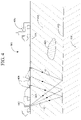
- FIG. 4 illustrates land seismic data acquisition
- FIGS. 5A and 5B illustrate low-wavenumber component of gradient and high-wavenumber component of gradient
- FIG. 6 is a workflow of a RFWI method according to an embodiment
- FIG. 7 is a workflow of a RFWI method according to another embodiment
- FIG. 8 is a schematic diagram of a computing device that can implement any of the methods discussed herein;
- FIGS. 9A and 9B are dip vertical slices of sediment flood reverse time migration before and after applying the RFWI method according to an embodiment
- FIGS. 10A and 10B are strike vertical slices of sediment flood reverse time migration before and after applying the RFWI method according to an embodiment.
- FIGS. 11A and 11B illustrate surface offset gathers before and after applying the RFWI method according to an embodiment.
- FIG. 2 is a flowchart of a method 200 according to an embodiment, and it is set forth at the beginning of this section to provide a roadmap for the ensuing descriptions of various embodiments and enablement aspects.
- Method 200 includes receiving a seismic dataset at 210 , generating a model-based dataset corresponding to the seismic dataset, and calculating a gradient of an objective function measuring the difference between the seismic dataset and the model-based dataset at 220 .
- Method 200 further includes updating the density model using a high-wavenumber component of the gradient at 230 .
- method 200 After regenerating the model-based dataset for the subsurface formation and calculating an updated gradient of an updated objective function at 240 , method 200 includes updating the velocity model using a low-wavenumber component of the updated gradient at 250 . Finally, a structural image of the subsurface formation is generated using the updated velocity at 260 , in order to plan a drilling path through the subsurface formation.
- the structural image may be used for other purposes, such as, for example, determining presence and location of mineral deposits.
- Steps 220 - 250 may be performed repeatedly. Alternatively or additionally, steps 220 - 230 may be performed with iteratively enhanced density models before performing steps 240 and 250 , which may also be performed with iteratively enhanced velocity models. In one embodiment, steps 220 - 250 are performed a until a predetermined condition is met. The condition may be a predetermined number of iterations or a convergence criterion.
- anisotropy, elastic effects and attenuation are taken into consideration in steps 220 and/or 240 .
- the updating in step 230 and/or 250 may be subject to constraints so as the updated density model and/or velocity model to be closer to a physical reality of the explored subsurface than the density and/or velocity model prior to the respective updating.
- the constraints may be based on additional structural information such as well logs.
- the density model may also be updated in step 250 .
- a reflectivity model may be updated instead of the density model in step 230 .
- FIG. 3 illustrates marine seismic data acquisition.
- a vessel 310 tows at least one cable 314 housing plural seismic sensors 312 .
- Cable 314 and seismic sensors 312 are referred to as a streamer 316 .
- Vessel 310 may tow plural parallel streamers (only one is visible in this vertical view).
- the streamers may lie in a plane at a constant depth z 1 relative to the ocean surface 318 .
- the plural streamers may be slanted with respect to the ocean surface as disclosed in U.S. Pat. No. 4,992,992, the entire content of which is incorporated herein by reference.
- the streamers may have a curved profile as described, for example, in U.S. Pat. No. 8,593,904, the entire content of which is incorporated herein by reference.
- Vessel 310 may also tow a seismic source 320 configured to generate acoustic waves that penetrate the seafloor 324 and are reflected, for example, at the layer interface 326 (e.g., by a reflecting structure R). Reflected acoustic waves may be detected by a seismic sensor as up-going from the seafloor or after being reflected by the water surface.
- FIG. 3 illustrates two wave-propagating paths from the source to a sensor 312 (here, down-going segments are labeled 321 and up-going segments 322 ).
- FIG. 4 illustrates seismic data being acquired on land.
- Land seismic data acquisition system 400 includes a source 402 carried by a truck and consisting of a vibrator configured to generate a seismic excitation, seismic sensors 404 that detect seismic waves and a recorder 406 (also mounted on a truck) for storing the seismic data generated by the sensors.
- Source 402 , sensors 404 and recorder 406 are positioned on the surface of the ground 408 but, alternatively or additionally, sensors and source may be buried underground.
- the seismic excitation generated by source 402 propagates as surface waves 410 (known as ground roll or Rayleigh waves), and penetrates underground as transmitted waves 412 that are reflected (see waves 414 ) when encountering an interface 415 between two geological layers 416 and 418 (with different seismic wave propagation speeds).
- the seismic excitation is a combination of P-waves (pressure waves) and S-waves (shear waves).
- P-waves pressure waves
- S-waves shear waves
- Sensors 404 detect both the surface waves and the reflected waves, and are typically geophones (while hydrophones are more often used in a marine environment). However, multi-sensors, geophones, hydrophones, differential pressure sensors and accelerometers may be used as seismic sensors in a marine environment and on land. Note also that the sensors may be deployed temporarily or left for repeated measurements at different calendar times, may be housed in towed cables or placed at the ocean bottom, may be buried at different locations or placed along a wellbore, etc. The image of the underground geological formation enables assessing the presence and location of hydrocarbon reservoirs such as 420 .
- FWI estimates properties of the subsurface, such as P-wave velocity, by minimizing the difference between the recorded seismic data d and synthetic seismic data ⁇ tilde over (d) ⁇ .
- Synthetic data may be obtained by forward modeling using a current velocity and/or density model. For example, in an approach using velocity model only, synthetic data is obtained using the acoustic constant-density wave equation:
- ⁇ 2 ⁇ p ⁇ t 2 v 2 ⁇ ⁇ 2 ⁇ p + f , ( 2 )
- p is the wavefield that is to be extracted at the sensor locations to obtain ⁇ tilde over (d) ⁇
- v is the current velocity model
- ⁇ 2 is the Laplacian operator
- f is a source term.
- the gradient g can be efficiently calculated using an adjoint-state method (as described in the previously-mentioned article by Tarantola):
- Conventional FWI performs: (A) generating synthetic data d using a current velocity model, (B) calculating residual between recorded seismic data and synthetic data d ⁇ tilde over (d) ⁇ , (C) calculating the gradient of the objective function using equation (4), and (D) updating the velocity model as in equation (3). Steps (A)-(D) are repeated until a stop condition is met. The steps may be repeated for several frequencies or frequency bands until a satisfactory result is achieved (as described in the article, “Seismic waveform inversion in the frequency domain, Part 1: Theory and verification in a physical scale model,” by R. G. Pratt, published in Geophysics , Vol. 64, No. 3, pp. 888-901, 1999, and in the article, “Multiscale seismic waveform inversion,” by Bunks et al., published in Geophysics , Vol. 60, No. 5, pp. 1457-1473, 1995, which are incorporated herein by references).
- reflection data also contains information about deeper areas of the model.
- reflection data has been used by ray-based tomography methods to derive deep and low-wavenumber updates (see, e.g., “Stereotomography,” by G. Lambaré, published in Geophysics , Vol. 73, No. 5, pp. VE25-VE34, 2008).
- the high-wavenumber component also known as migration term or migration “smile”
- the low-wavenumber component also known as tomographic term or “rabbit ears.”
- FIGS. 5A and 5B illustrate these gradient components as nuances of gray in a vertical slice. While the migration term is more directly associated with the practical challenges previously described, the tomographic term is generated along the wavepath and provides a low-wavenumber update to the velocity model, including deeper areas, beyond the reach of transmitted waves.
- a different FWI method needs to be used, i.e., a reflection FWI (RFWI).
- RFWI reflection FWI
- a first requirement for RFWI is to extract the low-wavenumber component of the gradient in order to avoid interference from the migration term.
- the gradient components can be distinguished based on the direction of propagation of the source and residual wavefields (as described in the above-cited article by P. Mora, which is incorporated by reference in its entirety).
- the low-wavenumber component is formed by cross-correlation of wavefields traveling in the same direction, while the high-wavenumber component is formed by wavefields traveling in opposite directions.
- the separation can be achieved in many ways, such as inverse-scattering imaging condition (as described in the article, “A robust FWI gradient for high-resolution velocity model building,” by Ramos-Martinez et al., published in SEG Technical Program Expanded Abstracts 2016, pp. 1258-1262), wavefield decomposition (as described in the article, “Reflection FWI,” by Irabor et al., published in SEG Technical Program Expanded Abstracts 2016, pp. 1136-1140), and Born modeling (as described in the article, “Earth-model building from shallow to deep with full-waveform inversion,” by Vigh et al., published in The Leading Edge , December 2016, pp. 1025-1030). All cited articles are incorporated by reference in their entirety.
- the above-described techniques for generating synthetic data and calculating low-wavenumber and high-wavenumber components of an objective function's gradient are relevant to both steps 220 and 240 of the method illustrated in FIG. 2 .
- the low-wavenumber and high-wavenumber components are used separately in method 200 .
- FIG. 6 A workflow of a method according to an embodiment is illustrated in FIG. 6 .
- a synthetic (model-based) dataset is generated at 630 by solving, for example, the acoustic wave equation with variable density (p):
- Additional information 615 may be used to constrain density and/or velocity models. For example, additional model properties such as anisotropy or attenuation parameters may be extracted from well log information. These additional properties may also be updated when updating the density and/or the velocity model.
- An objective function measuring the difference between the recorded seismic dataset and the synthetic dataset is calculated based on the residuals between the two datasets. Then, the high-wavenumber component of the objective function's gradient relative to the model parameters is calculated using equation (5). This manner of processing is based on comparing the synthetic and the recorded datasets.
- the density model is updated at 640 using this high-wavenumber component.
- a velocity perturbation related to the high-wavenumber component may be converted into density perturbation using, for example, Gardner's relation (as described in the article, “Formation velocity and density—the diagnostic basics for stratigraphic traps,” by Gardner et al., published in Geophysics , Vol. 39, No. 6, pp. 770-780, 1974, which is incorporated herein by reference in its entirety).
- a new synthetic dataset is generated using the velocity model and the updated density model, for example, by solving the acoustic wave equation with variable density (equation (6)). Then, at 650 , an updated objective function is calculated based on residual between recorded seismic dataset and new synthetic dataset. A low-wavenumber component of the updated objective function's gradient may then be calculated using equation (5). As pointed out above, this manner of processing is based on comparing the synthetic and the recorded datasets. At 660 , the velocity model is updated using this low-wavenumber component.
- Steps 630 - 660 may be repeated until a stop criterion is reached.
- the stop criterion may be a predetermined number of iterations.
- the outcome (models) of a current iteration may be compared with the outcome of one or more prior iterations and the optimization is stopped when significant improvement is no longer observed.
- the flow can also be repeated for several frequencies or frequency bands until a satisfactory result is achieved.
- Pre-processing (such as wavelength filtering) may be applied to the density model and/or the velocity model prior to steps 640 and 660 .
- the velocity model may be updated in addition to updating the density model.
- the reflectivity model may be updated instead of the density model.
- the updated objective function may be calculated differently than how the objective function is calculated in step 640 .
- Alternative ways of calculating objective function are L2 norm (as in equation (1)), cross-correlation of corresponding traces, or a data matching approach.
- the backscattered energy is generated by the density contrasts introduced in the first phase (step 640 ). This, in turn, yields the “rabbit ears” (low-wavenumber component of the updated objective function's gradient) used to update the velocity model in the second phase (step 660 ).
- the first phase does not change the kinematics of the velocity model that is updated in the second phase.
- the density and velocity models may be updated locally, in a predefined region, and the updating may be constrained by incorporating additional a priori information, such as, 4D differences or a tomographic Earth model update, etc.
- Imposing numerical optimization constraints may promote a specific behavior or belief in the Earth model, such as bound, or box constraint, edge-preserving constraint, total-variation constraint, hinge-loss one-sided constraint, etc., and all possible combinations of the above.
- the software implementation may use different modeling engines, such as Kirchhoff, downward continuation, two-way wave equation or beam, or combinations of these modeling engines.
- the above methods may use subsets of the recorded dataset, such as the near or far offsets, data in a specific time or space window. Different subsets may be used for updating the density model and for updating the velocity model.
- the model-based dataset generation and updating may be performed in different domains such as temporal, frequency, curvelet, etc., and over one dimension, two dimensions, or three dimensions.
- Steps 730 and 750 correspond to steps 630 and 650 .
- Steps 640 and 660 are divided into more explicit sub-steps to emphasize that the residues are calculated first at 735 and 755 , and are then used to update in turn the density and velocity models, at 740 and 760 , respectively.
- Computing device 800 of FIG. 8 is an exemplary computing structure that may be used in connection with such a system.
- One advantage of the above-described embodiments i.e., using the high-wavenumber component of the gradient to update the density model without changing the kinematics of the model
- reflectivity-based inversions is a definite decrease of computing costs, since extra propagations are not required to explicitly compute the scattered wavefields during the velocity update, which is the case for reflectivity-based methods.
- the computing converges to physically meaningful results faster.
- Exemplary computing device 800 suitable for performing the activities described in the exemplary embodiments may include a server 801 .
- a server 801 may include a central processor (CPU) 802 and a graphics processor (GPU) coupled to a random access memory (RAM) 804 and to a read-only memory (ROM) 806 .
- ROM 806 may also be other types of storage media to store programs, such as programmable ROM (PROM), erasable PROM (EPROM), etc.
- Processor 802 may communicate with other internal and external components through input/output (I/O) circuitry 808 and bussing 810 to provide control signals and the like.
- I/O input/output
- Processor 802 carries out a variety of functions as are known in the art, as dictated by software and/or firmware instructions.
- Server 801 may also include one or more data storage devices, including hard drives 812 , CD-ROM drives 814 and other hardware capable of reading and/or storing information, such as DVD, etc.
- software for carrying out the above-discussed steps may be stored and distributed on a CD-ROM or DVD 816 , a USB storage device 818 or other form of media capable of portably storing information. These storage media may be inserted into, and read by, devices such as CD-ROM drive 814 , disk drive 812 , etc.
- Server 801 may be coupled to a display 820 , which may be any type of known display or presentation screen, such as LCD, plasma display, cathode ray tube (CRT), etc.
- a user input interface 822 is provided, including one or more user interface mechanisms such as a mouse, keyboard, microphone, touchpad, touch screen, voice-recognition system, etc.
- Server 801 may be coupled to other devices, such as sources, seismic sensors, etc.
- the server may be part of a larger network configuration as in a global area network (GAN) such as the Internet 828 , which allows ultimate connection to various landline and/or mobile computing devices.
- GAN global area network
- a deep-water (1500-3500 m) wide-area azimuth (+/ ⁇ 8100 m and +/ ⁇ 4200 m inline and cross-line offsets) example illustrated in FIGS. 9-11 shows that the above-described RFWI methods improve the velocity model in an area below the salt, to a depth far greater than conventional FWI methods could, which resulted in a significant improvement of the image of the exploration target layers.
- the FWI gradient's high-wavenumber and low-wavenumber components have been obtained based on the propagation direction of the wavefields, and have been used alternately to update density and velocity models, respectively.
- the density model update introduces the deep reflectors needed for the recalculation of low-wavenumber component used for velocity model update.
- this RFWI method improves the velocity model for the sediment mini-basins, the salt and subsalt where both ray-based tomography and FWI had limited success, and yields a better salt geometry interpretation and subsalt image.
- FIGS. 9-11 illustrate data processing improvements when using RFWI.
- FIG. 9A is a dip vertical slice illustrating the target sediments, obtained by reverse time migration (RTM), before applying the RFWI method
- FIG. 9B shows the same slice after applying the RFWI method according to an embodiment.
- Arrows 910 - 940 point to areas under the bottom of the salt (BOS) that were poorly imagined initially, and improved upon applying the RFWI method.
- FIG. 10A is a strike vertical slice (i.e., a slice perpendicular to the slice in FIG. 9A ) of the target sediments, obtained by RTM, before applying the RFWI method
- FIG. 10B shows the same slice after applying the RFWI method according to an embodiment.
- Arrows 1010 - 1040 point to areas under the BOS whose image is improved upon applying the RFWI method.
- FIG. 11A illustrates SOGs before applying RFWI method
- FIG. 11B illustrates the same SOGs after applying RFWI (labels 1110 - 1140 indicating where RFWI improves in SOGs definition and flatness).
- the disclosed exemplary embodiments provide a computing device, software instructions and a method for performing RFWI, updating density and velocity models of an explored underground formation separately using high-wavenumber and low-wavenumber of the FWI gradient, respectively. It should be understood that this description is not intended to limit the invention. On the contrary, the exemplary embodiments are intended to cover alternatives, modifications and equivalents, which are included in the spirit and scope of the invention as defined by the appended claims. Further, in the detailed description of the exemplary embodiments, numerous specific details are set forth in order to provide a comprehensive understanding of the claimed invention. However, one skilled in the art would understand that various embodiments may be practiced without such specific details.
Landscapes
- Engineering & Computer Science (AREA)
- Remote Sensing (AREA)
- Physics & Mathematics (AREA)
- Life Sciences & Earth Sciences (AREA)
- Acoustics & Sound (AREA)
- Environmental & Geological Engineering (AREA)
- Geology (AREA)
- General Life Sciences & Earth Sciences (AREA)
- General Physics & Mathematics (AREA)
- Geophysics (AREA)
- Geophysics And Detection Of Objects (AREA)
Abstract
Description
J=∥d−{tilde over (d)}∥ 2 (1)
∥⋅∥ denoting the L-2 norm.
where p is the wavefield that is to be extracted at the sensor locations to obtain {tilde over (d)}, v is the current velocity model, ∇2 is the Laplacian operator and f is a source term.
v k+1 =v k−αk g k, (3)
where k denotes the iteration index, α is a constant scalar called the step-length (which may be obtained by a line-search) and g represents the gradient of J, i.e., the derivative of J with respect to the model parameters being inverted.
where λ is the back-propagated data residual (d−{tilde over (d)}).
-
- 1. A reflection is not generated by a contrast in one parameter alone. It can be formed by a contrast in the P-wave velocity, the density, or by variations in both parameters.
- 2. It requires a good background velocity model, containing some level of contrast or detail, to both generate and correctly place the reflections and avoid the so-called cycle-skipping (as pointed out in “An overview of full-waveform inversion in exploration geophysics,” by Virieux et al., published in Geophysics, Vol. 74, No. 6, pp. WCC1-WCC26, 2009).
- 3. It requires elastic modeling, or at least an accurate density model, to obtain amplitudes comparable to the recorded seismic data (as pointed out in “On the velocity-density ambiguity in acoustic full-waveform inversion,” by A. Guitton, presented at the 76th EAGE Conference and Exhibition in Amsterdam, The Netherlands, 2014).
Claims (20)
Priority Applications (1)
| Application Number | Priority Date | Filing Date | Title |
|---|---|---|---|
| US15/865,905 US11487036B2 (en) | 2017-01-12 | 2018-01-09 | Reflection full waveform inversion methods with density and velocity models updated separately |
Applications Claiming Priority (2)
| Application Number | Priority Date | Filing Date | Title |
|---|---|---|---|
| US201762445344P | 2017-01-12 | 2017-01-12 | |
| US15/865,905 US11487036B2 (en) | 2017-01-12 | 2018-01-09 | Reflection full waveform inversion methods with density and velocity models updated separately |
Publications (2)
| Publication Number | Publication Date |
|---|---|
| US20180196154A1 US20180196154A1 (en) | 2018-07-12 |
| US11487036B2 true US11487036B2 (en) | 2022-11-01 |
Family
ID=62783045
Family Applications (1)
| Application Number | Title | Priority Date | Filing Date |
|---|---|---|---|
| US15/865,905 Active 2040-11-23 US11487036B2 (en) | 2017-01-12 | 2018-01-09 | Reflection full waveform inversion methods with density and velocity models updated separately |
Country Status (1)
| Country | Link |
|---|---|
| US (1) | US11487036B2 (en) |
Families Citing this family (19)
| Publication number | Priority date | Publication date | Assignee | Title |
|---|---|---|---|---|
| US11487036B2 (en) * | 2017-01-12 | 2022-11-01 | Cgg Services Sas | Reflection full waveform inversion methods with density and velocity models updated separately |
| CN108802818B (en) * | 2018-06-11 | 2019-06-25 | 中国石油大学(北京) | The chromatography component extraction method of original gradient in a kind of full waveform inversion |
| CN109116415B (en) * | 2018-10-11 | 2020-06-09 | 中国石油天然气股份有限公司 | Seismic wave data separation method, device and storage medium |
| CN109116424B (en) * | 2018-10-11 | 2020-06-09 | 中国石油天然气股份有限公司 | Low wave number noise separation method and device for seismic wave data and storage medium |
| CN111665545A (en) * | 2019-03-07 | 2020-09-15 | 中普宝信(北京)科技有限公司 | Acoustic parameter acquisition method for rare metal detection |
| CN111665553A (en) * | 2019-03-07 | 2020-09-15 | 中普宝信(北京)科技有限公司 | Acoustic parameter acquisition method for river and lake sediment detection |
| US11340368B2 (en) * | 2019-03-21 | 2022-05-24 | Saudi Arabian Oil Company | Generating a velocity model and a density model of a subsurface structure of a reservoir |
| CN112630830B (en) * | 2019-10-08 | 2024-04-09 | 中国石油化工股份有限公司 | Reflection wave full waveform inversion method and system based on Gaussian weighting |
| CN112649843B (en) * | 2019-10-10 | 2024-01-23 | 中国石油化工股份有限公司 | Initial model construction method and system based on layer speed constraint |
| CN110764146B (en) * | 2019-10-24 | 2020-05-19 | 南京信息工程大学 | Space cross-correlation elastic wave reflection waveform inversion method based on acoustic wave operator |
| US11255995B2 (en) * | 2020-03-25 | 2022-02-22 | Advanced Geophysical Technology Inc. | Methods and systems for determining subsurface feature using broadband full waveform inversion |
| US11320557B2 (en) | 2020-03-30 | 2022-05-03 | Saudi Arabian Oil Company | Post-stack time domain image with broadened spectrum |
| CN113589366B (en) * | 2020-04-30 | 2023-10-20 | 中国石油化工股份有限公司 | Broadband fusion modeling method based on full waveform inversion |
| CN112463401A (en) * | 2020-10-30 | 2021-03-09 | 中国石油天然气集团有限公司 | Seismic data correlation method and device based on GPU |
| US11880009B2 (en) * | 2021-03-29 | 2024-01-23 | Cgg Services Sas | Methods and devices for joint time-lapse full-waveform inversion with a time-lag cost function |
| US11867857B2 (en) * | 2021-07-13 | 2024-01-09 | Saudi Arabian Oil Company | Method and system for updating a seismic velocity model |
| US20230037886A1 (en) * | 2021-08-05 | 2023-02-09 | Saudi Arabian Oil Company | Method and system for determination of seismic propagation velocities using nonlinear transformations |
| CN113589385B (en) * | 2021-08-11 | 2023-08-04 | 成都理工大学 | Reservoir characteristic inversion method based on seismic scattered wave field analysis |
| CN116009085B (en) * | 2023-02-02 | 2024-03-12 | 哈尔滨工业大学 | Soft stratum transverse wave speed measurement method and device based on full waveform inversion |
Citations (51)
| Publication number | Priority date | Publication date | Assignee | Title |
|---|---|---|---|---|
| US4953142A (en) * | 1989-01-06 | 1990-08-28 | Marathon Oil Company | Model-based depth processing of seismic data |
| US4992992A (en) | 1988-10-21 | 1991-02-12 | Western Atlas International, Inc. | Processing for seismic data from slanted cable |
| US20070203673A1 (en) * | 2005-11-04 | 2007-08-30 | Sherrill Francis G | 3d pre-stack full waveform inversion |
| US20070282535A1 (en) * | 2006-05-31 | 2007-12-06 | Bp Corporation North America Inc. | System and method for 3d frequency domain waveform inversion based on 3d time-domain forward modeling |
| US20100118651A1 (en) * | 2008-11-10 | 2010-05-13 | Chevron U.S.A. Inc. | Method for generation of images related to a subsurface region of interest |
| US20100142316A1 (en) * | 2008-12-07 | 2010-06-10 | Henk Keers | Using waveform inversion to determine properties of a subsurface medium |
| US20100302906A1 (en) * | 2009-05-28 | 2010-12-02 | Chevron U.S.A. Inc. | Method for wavefield-based data processing including utilizing multiples to determine subsurface characteristics of a suburface region |
| US20100322032A1 (en) * | 2009-06-17 | 2010-12-23 | Shin Chang-Soo | Apparatus and method for imaging subsurface structure of target area by using waveform inversion |
| US20110000678A1 (en) * | 2008-03-21 | 2011-01-06 | Krebs Jerome R | Efficient Method For Inversion of Geophysical Data |
| US20110085413A1 (en) * | 2009-10-08 | 2011-04-14 | Westerngeco L. L. C. | Migration Velocity Analysis Using Seismic Data |
| US20110090760A1 (en) * | 2009-10-19 | 2011-04-21 | James Rickett | Full-waveform inversion in the traveltime domain |
| US20110317519A1 (en) * | 2010-06-24 | 2011-12-29 | Chevron U.S.A. Inc. | Reverse time migration with absorbing and random boundaries |
| US20120259601A1 (en) * | 2011-04-05 | 2012-10-11 | Rodrigo Fuck | Waveform inversion using a response of forward modeling |
| US8437998B2 (en) * | 2010-09-27 | 2013-05-07 | Exxonmobil Upstream Research Company | Hybrid method for full waveform inversion using simultaneous and sequential source method |
| US20130138408A1 (en) * | 2011-11-29 | 2013-05-30 | Sunwoong Lee | Methods for Approximating Hessian Times Vector Operation in Full Wavefield Inversion |
| US20130238249A1 (en) * | 2012-03-09 | 2013-09-12 | Cggveritas Services Sa | Seismic reflection full waveform inversion for reflected seismic data |
| US20130311149A1 (en) * | 2012-05-17 | 2013-11-21 | Yaxun Tang | Tomographically Enhanced Full Wavefield Inversion |
| US8593904B2 (en) * | 2010-10-14 | 2013-11-26 | Cggveritas Services Sa | Method and device to acquire seismic data |
| US20130343154A1 (en) * | 2012-04-19 | 2013-12-26 | Cggveritas Services Sa | Seismic data processing including compensating for source and receiver ghost effects in reverse time migration |
| US20140129479A1 (en) * | 2011-05-23 | 2014-05-08 | Imperial Innovations Limited | Method to aid in the exploration, mine design, evaluation and/or extraction of metalliferous mineral and/or diamond deposits |
| US20150012256A1 (en) * | 2011-03-30 | 2015-01-08 | Partha S. Routh | Convergence Rate of Full Wavefield Inversion Using Spectral Shaping |
| US20150120200A1 (en) * | 2013-10-28 | 2015-04-30 | Bp Corporation North America Inc. | Two stage seismic velocity model generation |
| US20150362622A1 (en) * | 2014-06-17 | 2015-12-17 | Huseyin Denli | Fast Viscoacoustic and Viscoelastic Full Wavefield Inversion |
| US20160047924A1 (en) * | 2014-08-14 | 2016-02-18 | Christine Krohn | Determination of Subsurface Properties in the Vicinity of a Well by Full Wavefield Inversion |
| US20160097870A1 (en) * | 2014-10-03 | 2016-04-07 | Partha S. Routh | Seismic Survey Design Using Full Wavefield Inversion |
| US20160146961A1 (en) * | 2014-11-25 | 2016-05-26 | Cgg Services Sa | Method for elastic model perturbation estimation from reverse time migration |
| US20160187506A1 (en) * | 2014-04-14 | 2016-06-30 | Cgg Services Sa | Method for iterative inversion of data from composite sources |
| US20160216389A1 (en) * | 2015-01-23 | 2016-07-28 | Advanced Geophysical Technology Inc. | Beat tone full waveform inversion |
| US20160238729A1 (en) * | 2013-10-29 | 2016-08-18 | Imperial Innovations Limited | Method of, and apparatus for, full waveform inversion |
| US20160245941A1 (en) * | 2015-02-20 | 2016-08-25 | Pgs Geophysical As | Amplitude-versus-angle Analysis for Quantitative Interpretation |
| US20160282490A1 (en) * | 2015-03-27 | 2016-09-29 | Cgg Services Sa | Full waveform inversion method for seismic data processing using preserved amplitude reverse time migration |
| US20160320505A1 (en) * | 2014-01-10 | 2016-11-03 | Cgg Services (U.S.) Inc. | Device and method for mitigating cycle-skipping in full waveform inversion |
| US20160334527A1 (en) * | 2014-01-10 | 2016-11-17 | Statoil Petroleum As | Determining a component of a wave field |
| US20170131418A1 (en) * | 2015-11-05 | 2017-05-11 | Cgg Services Sa | Device and method for full waveform inversion |
| US20170168178A1 (en) * | 2015-12-10 | 2017-06-15 | Pgs Geophysical As | Velocity Model Update with an Inversion Gradient |
| US20170168177A1 (en) * | 2015-12-11 | 2017-06-15 | Ion Geophysical Corporation | System and method for reconstructed wavefield inversion |
| US20170176613A1 (en) * | 2015-12-18 | 2017-06-22 | William A. Burnett | Method To Design Geophysical Surveys Using Full Wavefield Inversion Point- Spread Function Analysis |
| US9702993B2 (en) * | 2013-05-24 | 2017-07-11 | Exxonmobil Upstream Research Company | Multi-parameter inversion through offset dependent elastic FWI |
| US20170205520A1 (en) * | 2014-06-19 | 2017-07-20 | Westerngeco Llc | System and Method to Acquire Ultra-long Offset Seismic Data for Full Waveform Inversion (FWI) Using Unmanned Marine Vehicle (UMV) |
| US20180045839A1 (en) * | 2016-08-12 | 2018-02-15 | Yaxun Tang | Tomographically Enhanced Full Wavefield Inversion |
| US9910174B2 (en) * | 2014-07-25 | 2018-03-06 | Seoul National University R&Db Foundation | Seismic imaging apparatus and method for performing iterative application of direct waveform inversion |
| US9921328B2 (en) * | 2013-06-13 | 2018-03-20 | Cgg Services Sas | Adaptable seismic source for seismic surveys and method |
| US20180120464A1 (en) * | 2015-03-26 | 2018-05-03 | Schlumberger Technology Corporation | Seismic Waveform Inversion |
| US20180164453A1 (en) * | 2015-05-29 | 2018-06-14 | Sub Salt Solutions Limited | Method for Improved Geophysical Investigation |
| US20180172858A1 (en) * | 2016-12-20 | 2018-06-21 | Ion Geophysical Corporation | System and method for reconstructed wavefield imaging |
| US20180196154A1 (en) * | 2017-01-12 | 2018-07-12 | Cgg Services Sas | Reflection full waveform inversion methods with density and velocity models updated separately |
| US10048394B2 (en) * | 2013-10-01 | 2018-08-14 | Cgg Services Sas | System and method for discontinuous spectrum emission in seismic exploration |
| US20190196038A1 (en) * | 2017-12-22 | 2019-06-27 | Dennis E. Willen | Full Wavefield Inversion of Ocean Bottom Seismic Data |
| US20190257968A1 (en) * | 2018-02-21 | 2019-08-22 | Pgs Geophysical As | Inversion with Exponentially Encoded Seismic Data |
| US20190302293A1 (en) * | 2018-03-30 | 2019-10-03 | Cgg Services Sas | Methods using travel-time full waveform inversion for imaging subsurface formations with salt bodies |
| US10520619B2 (en) * | 2015-10-15 | 2019-12-31 | Exxonmobil Upstream Research Company | FWI model domain angle stacks with amplitude preservation |
-
2018
- 2018-01-09 US US15/865,905 patent/US11487036B2/en active Active
Patent Citations (52)
| Publication number | Priority date | Publication date | Assignee | Title |
|---|---|---|---|---|
| US4992992A (en) | 1988-10-21 | 1991-02-12 | Western Atlas International, Inc. | Processing for seismic data from slanted cable |
| US4953142A (en) * | 1989-01-06 | 1990-08-28 | Marathon Oil Company | Model-based depth processing of seismic data |
| US20070203673A1 (en) * | 2005-11-04 | 2007-08-30 | Sherrill Francis G | 3d pre-stack full waveform inversion |
| US20070282535A1 (en) * | 2006-05-31 | 2007-12-06 | Bp Corporation North America Inc. | System and method for 3d frequency domain waveform inversion based on 3d time-domain forward modeling |
| US20110000678A1 (en) * | 2008-03-21 | 2011-01-06 | Krebs Jerome R | Efficient Method For Inversion of Geophysical Data |
| US20100118651A1 (en) * | 2008-11-10 | 2010-05-13 | Chevron U.S.A. Inc. | Method for generation of images related to a subsurface region of interest |
| US20100142316A1 (en) * | 2008-12-07 | 2010-06-10 | Henk Keers | Using waveform inversion to determine properties of a subsurface medium |
| US20100302906A1 (en) * | 2009-05-28 | 2010-12-02 | Chevron U.S.A. Inc. | Method for wavefield-based data processing including utilizing multiples to determine subsurface characteristics of a suburface region |
| US20100322032A1 (en) * | 2009-06-17 | 2010-12-23 | Shin Chang-Soo | Apparatus and method for imaging subsurface structure of target area by using waveform inversion |
| US20110085413A1 (en) * | 2009-10-08 | 2011-04-14 | Westerngeco L. L. C. | Migration Velocity Analysis Using Seismic Data |
| US20110090760A1 (en) * | 2009-10-19 | 2011-04-21 | James Rickett | Full-waveform inversion in the traveltime domain |
| US20110317519A1 (en) * | 2010-06-24 | 2011-12-29 | Chevron U.S.A. Inc. | Reverse time migration with absorbing and random boundaries |
| US8437998B2 (en) * | 2010-09-27 | 2013-05-07 | Exxonmobil Upstream Research Company | Hybrid method for full waveform inversion using simultaneous and sequential source method |
| US8593904B2 (en) * | 2010-10-14 | 2013-11-26 | Cggveritas Services Sa | Method and device to acquire seismic data |
| US20150012256A1 (en) * | 2011-03-30 | 2015-01-08 | Partha S. Routh | Convergence Rate of Full Wavefield Inversion Using Spectral Shaping |
| US20120259601A1 (en) * | 2011-04-05 | 2012-10-11 | Rodrigo Fuck | Waveform inversion using a response of forward modeling |
| US20140129479A1 (en) * | 2011-05-23 | 2014-05-08 | Imperial Innovations Limited | Method to aid in the exploration, mine design, evaluation and/or extraction of metalliferous mineral and/or diamond deposits |
| US20130138408A1 (en) * | 2011-11-29 | 2013-05-30 | Sunwoong Lee | Methods for Approximating Hessian Times Vector Operation in Full Wavefield Inversion |
| US20130238249A1 (en) * | 2012-03-09 | 2013-09-12 | Cggveritas Services Sa | Seismic reflection full waveform inversion for reflected seismic data |
| US10310123B2 (en) * | 2012-03-09 | 2019-06-04 | Cgg Services Sas | Seismic reflection full waveform inversion for reflected seismic data |
| US20130343154A1 (en) * | 2012-04-19 | 2013-12-26 | Cggveritas Services Sa | Seismic data processing including compensating for source and receiver ghost effects in reverse time migration |
| US20130311149A1 (en) * | 2012-05-17 | 2013-11-21 | Yaxun Tang | Tomographically Enhanced Full Wavefield Inversion |
| US9702993B2 (en) * | 2013-05-24 | 2017-07-11 | Exxonmobil Upstream Research Company | Multi-parameter inversion through offset dependent elastic FWI |
| US9921328B2 (en) * | 2013-06-13 | 2018-03-20 | Cgg Services Sas | Adaptable seismic source for seismic surveys and method |
| US10048394B2 (en) * | 2013-10-01 | 2018-08-14 | Cgg Services Sas | System and method for discontinuous spectrum emission in seismic exploration |
| US20150120200A1 (en) * | 2013-10-28 | 2015-04-30 | Bp Corporation North America Inc. | Two stage seismic velocity model generation |
| US20160238729A1 (en) * | 2013-10-29 | 2016-08-18 | Imperial Innovations Limited | Method of, and apparatus for, full waveform inversion |
| US20160334527A1 (en) * | 2014-01-10 | 2016-11-17 | Statoil Petroleum As | Determining a component of a wave field |
| US20160320505A1 (en) * | 2014-01-10 | 2016-11-03 | Cgg Services (U.S.) Inc. | Device and method for mitigating cycle-skipping in full waveform inversion |
| US20160187506A1 (en) * | 2014-04-14 | 2016-06-30 | Cgg Services Sa | Method for iterative inversion of data from composite sources |
| US20150362622A1 (en) * | 2014-06-17 | 2015-12-17 | Huseyin Denli | Fast Viscoacoustic and Viscoelastic Full Wavefield Inversion |
| US20170205520A1 (en) * | 2014-06-19 | 2017-07-20 | Westerngeco Llc | System and Method to Acquire Ultra-long Offset Seismic Data for Full Waveform Inversion (FWI) Using Unmanned Marine Vehicle (UMV) |
| US9910174B2 (en) * | 2014-07-25 | 2018-03-06 | Seoul National University R&Db Foundation | Seismic imaging apparatus and method for performing iterative application of direct waveform inversion |
| US20160047924A1 (en) * | 2014-08-14 | 2016-02-18 | Christine Krohn | Determination of Subsurface Properties in the Vicinity of a Well by Full Wavefield Inversion |
| US20160097870A1 (en) * | 2014-10-03 | 2016-04-07 | Partha S. Routh | Seismic Survey Design Using Full Wavefield Inversion |
| US20160146961A1 (en) * | 2014-11-25 | 2016-05-26 | Cgg Services Sa | Method for elastic model perturbation estimation from reverse time migration |
| US20160216389A1 (en) * | 2015-01-23 | 2016-07-28 | Advanced Geophysical Technology Inc. | Beat tone full waveform inversion |
| US20160245941A1 (en) * | 2015-02-20 | 2016-08-25 | Pgs Geophysical As | Amplitude-versus-angle Analysis for Quantitative Interpretation |
| US20180120464A1 (en) * | 2015-03-26 | 2018-05-03 | Schlumberger Technology Corporation | Seismic Waveform Inversion |
| US20160282490A1 (en) * | 2015-03-27 | 2016-09-29 | Cgg Services Sa | Full waveform inversion method for seismic data processing using preserved amplitude reverse time migration |
| US20180164453A1 (en) * | 2015-05-29 | 2018-06-14 | Sub Salt Solutions Limited | Method for Improved Geophysical Investigation |
| US10520619B2 (en) * | 2015-10-15 | 2019-12-31 | Exxonmobil Upstream Research Company | FWI model domain angle stacks with amplitude preservation |
| US20170131418A1 (en) * | 2015-11-05 | 2017-05-11 | Cgg Services Sa | Device and method for full waveform inversion |
| US20170168178A1 (en) * | 2015-12-10 | 2017-06-15 | Pgs Geophysical As | Velocity Model Update with an Inversion Gradient |
| US20170168177A1 (en) * | 2015-12-11 | 2017-06-15 | Ion Geophysical Corporation | System and method for reconstructed wavefield inversion |
| US20170176613A1 (en) * | 2015-12-18 | 2017-06-22 | William A. Burnett | Method To Design Geophysical Surveys Using Full Wavefield Inversion Point- Spread Function Analysis |
| US20180045839A1 (en) * | 2016-08-12 | 2018-02-15 | Yaxun Tang | Tomographically Enhanced Full Wavefield Inversion |
| US20180172858A1 (en) * | 2016-12-20 | 2018-06-21 | Ion Geophysical Corporation | System and method for reconstructed wavefield imaging |
| US20180196154A1 (en) * | 2017-01-12 | 2018-07-12 | Cgg Services Sas | Reflection full waveform inversion methods with density and velocity models updated separately |
| US20190196038A1 (en) * | 2017-12-22 | 2019-06-27 | Dennis E. Willen | Full Wavefield Inversion of Ocean Bottom Seismic Data |
| US20190257968A1 (en) * | 2018-02-21 | 2019-08-22 | Pgs Geophysical As | Inversion with Exponentially Encoded Seismic Data |
| US20190302293A1 (en) * | 2018-03-30 | 2019-10-03 | Cgg Services Sas | Methods using travel-time full waveform inversion for imaging subsurface formations with salt bodies |
Non-Patent Citations (24)
| Title |
|---|
| A. Guitton, "On the velocity-density ambiguity in acoustic full-waveform inversion", 76th EAGE Conference & Exhibition, Amsterdam, The Netherlands, Jun. 16-19, 2014. |
| A. Ratcliffe et al., "Full Waveform Inversion—A North Sea OBC Case Study—Reloaded", 76th EAGE Conference & Exhibition, Jun. 16-19, 2014, Amsterdam, The Netherlands. |
| Albert Tarantola, "Inversion of seismic reflection data in the acoustic approximation", Geophysics, Aug. 1984, pp. 1259-1266, vol. 49, No. 8. |
| Amsalu Y. Anagaw et al., "Full waveform inversion with simultaneous sources using the full Newton Method", SEG Technical Program Expanded Abstracts, SEG Las Vegas 2012 Annual Meeting, Nov. 4-9, 2012, pp. 1-5. |
| Carey Bunks et al., "Multiscale seismic waveform inversion", Geophysics, Sep.-Oct. 1995, pp. 1457-1473, vol. 60, No. 5. |
| Denes Vigh et al., "Earth-model building from shallow to deep with full-waveform inversion", The Leading Edge, Dec. 2016, pp. 1025-1030. |
| Faqi Liu et al., "An effective imaging condition for reverse-time migration using wavefield decomposition", Geophysics, Jan.-Feb. 2011, pp. S29-S39, vol. 76, No. 1. |
| G.H.F. Gardner et al., "Formation velocity and density—the diagnostic basics for stratigraphic traps", Geophysics, Dec. 1974, pp. 770-780, vol. 39, No. 6. |
| Gilles Lambaré, "Stereotomography", Geophysics, Sep.-Oct. 2008, pp. VE25-VE34, vol. 73, No. 5. |
| J. Virieux et al., "An overview of full-waveform inversion in exploration geophysics". Geophysics, Nov.-Dec. 2009, pp. WCC1-WCC-26, vol. 74, No. 6. |
| Jaime Ramos-Martinez et al., "A robust FWI gradient for high-resolution velocity model building", SEG Internationa Exposition and 86th Annual Meeting, Oct. 16-21, 2016, Dallas, Texas, pp. 1258-1262. |
| Jorge Nocedal et al., "Numerical optimization", Springer Series in Operations Research, 1999. |
| Kenneth Irabor et al., "Reflection FWI", SEG International Exposition and 86th Annual Meeting, Dallas, Texas, Oct. 16-21, 2016, pp. 1136-1140. |
| Michael Warner et al., "Adaptive waveform inversion: Theory", Geophysics, Nov.-Dec. 2016, pp. R429-R445, vol. 81, No. 6. |
| Michael Warner et al., "Anisotropic 3D full-waveform inversion", Geophysics, Mar.-Apr. 2013, pp. R59-R80, vol. 78, No. 2. |
| Nicolas Chazalnoel et al., "Revealing shallow and deep complex geological features with FWI: Lessons learned", 79th EAGE Conference & Exhibition, Paris, France, Jun. 12-15, 2017. |
| Nuno V. Da Silva et al., "A new parameter set for anisotropic multiparameter full-waveform inversion and application to a North Sea data set", Geophysics, Jul.-Aug. 2016, pp. U25-U38, vol. 81, No. 4. |
| Peter Mora, "Inversion = migration + tomography", Geophysics, Dec. 1989, pp. 1575-1586, vol. 54, No. 12. |
| R. Gerhard Pratt, "Seismic waveform inversion in the frequency domain, Part 1: Theory and verification in a physical scale model", Geophysics, May-Jun. 1999, pp. 888-901, vol. 64, No. 3. |
| Ramos-Martinez et al. (A robust FWI gradient for high-resolution velocity model building, 2016, SEG international Exposition and 86th Annual Meeting, pp. 1258-1262) (Year: 2016). * |
| Sheng Xu et al., "Inversion on Reflected Seismic Wave", SEG Las Vegas 2012 Annual Meeting, Nov. 4-9, 2012, Las Vegas, Nevada, pp. 1-7. |
| Wei Zhou et al., "Full waveform inversion of diving & reflected waves for velocity model building with impedance inversion based on scale separation". Geophysical Journal International, 2015, pp. 1535-1554, vol. 202. |
| Yaxun Tang et al., "Tomographically enhanced full wavefield inversion", SEG Houston 2013 Annual Meeting, Houston, Texas, Sep. 22-27, 2013, pp. 1037-1041. |
| Zhou et al. (Full waveform inversion of diving & reflected waves for velocity model building with impedance inversion based on scale separation, Geophys. J Int. (2015) 202, 1535-1551) (Year: 2015). * |
Also Published As
| Publication number | Publication date |
|---|---|
| US20180196154A1 (en) | 2018-07-12 |
Similar Documents
| Publication | Publication Date | Title |
|---|---|---|
| US11487036B2 (en) | Reflection full waveform inversion methods with density and velocity models updated separately | |
| US11048001B2 (en) | Methods using travel-time full waveform inversion for imaging subsurface formations with salt bodies | |
| US11428834B2 (en) | Processes and systems for generating a high-resolution velocity model of a subterranean formation using iterative full-waveform inversion | |
| US10386515B2 (en) | Method and apparatus for analyzing fractures using AVOAz inversion | |
| EP3073296B1 (en) | Full waveform inversion method for seismic data processing using preserved amplitude reverse time migration | |
| US8352190B2 (en) | Method for analyzing multiple geophysical data sets | |
| Warner et al. | Anisotropic 3D full-waveform inversion | |
| US9279898B2 (en) | Methods and systems for correction of streamer-depth bias in marine seismic surveys | |
| US10884148B2 (en) | Amplitude compensation of reverse time migration (RTM) gathers for AVO/AVA analysis | |
| US10353092B2 (en) | Velocity model update with an inversion gradient | |
| EP3358376B1 (en) | Method and apparatus for unambiguously estimating seismic anisotropy parameters | |
| AU2012202582B2 (en) | Methods and apparatus for seismic exploration using pressure changes caused by sea-surface variations | |
| US10345468B2 (en) | System and method for seismic data processing of seismic data sets with different spatial sampling and temporal bandwidths | |
| US9857489B2 (en) | System and method for ray based tomography guided by waveform inversion | |
| US10459097B2 (en) | Methods and systems for extrapolating wavefields | |
| US20220373703A1 (en) | Methods and systems for generating an image of a subterranean formation based on low frequency reconstructed seismic data | |
| US11635540B2 (en) | Methods and devices performing adaptive quadratic Wasserstein full-waveform inversion | |
| Cho et al. | Laplace–Fourier-domain full waveform inversion of deep-sea seismic data acquired with limited offsets | |
| US10782430B2 (en) | Method for seismic exploration using a multiple-inclusive source wavelet | |
| US20240295666A1 (en) | Joint preconditioning for time-lapse full waveform inversion method and system | |
| US20230305176A1 (en) | Determining properties of a subterranean formation using an acoustic wave equation with a reflectivity parameterization | |
| Biondi et al. | Target-oriented elastic full-waveform inversion through extended image-space redatuming | |
| WO2024194150A1 (en) | Determining angle gathers from inversion of velocity and reflectivity of a subterranean formation | |
| Liu et al. | Time-lapse full-waveform inversion for elastic TTI media |
Legal Events
| Date | Code | Title | Description |
|---|---|---|---|
| FEPP | Fee payment procedure |
Free format text: ENTITY STATUS SET TO UNDISCOUNTED (ORIGINAL EVENT CODE: BIG.); ENTITY STATUS OF PATENT OWNER: LARGE ENTITY |
|
| AS | Assignment |
Owner name: CGG SERVICES SAS, FRANCE Free format text: ASSIGNMENT OF ASSIGNORS INTEREST;ASSIGNORS:GOMES, ADRIANO;CHAZALNOEL, NICOLAS;REEL/FRAME:044624/0947 Effective date: 20180111 |
|
| STPP | Information on status: patent application and granting procedure in general |
Free format text: DOCKETED NEW CASE - READY FOR EXAMINATION |
|
| STPP | Information on status: patent application and granting procedure in general |
Free format text: NON FINAL ACTION MAILED |
|
| STPP | Information on status: patent application and granting procedure in general |
Free format text: RESPONSE TO NON-FINAL OFFICE ACTION ENTERED AND FORWARDED TO EXAMINER |
|
| STPP | Information on status: patent application and granting procedure in general |
Free format text: FINAL REJECTION MAILED |
|
| STCV | Information on status: appeal procedure |
Free format text: NOTICE OF APPEAL FILED |
|
| STCV | Information on status: appeal procedure |
Free format text: APPEAL BRIEF (OR SUPPLEMENTAL BRIEF) ENTERED AND FORWARDED TO EXAMINER |
|
| STCV | Information on status: appeal procedure |
Free format text: EXAMINER'S ANSWER TO APPEAL BRIEF MAILED |
|
| STCV | Information on status: appeal procedure |
Free format text: ON APPEAL -- AWAITING DECISION BY THE BOARD OF APPEALS |
|
| STCV | Information on status: appeal procedure |
Free format text: BOARD OF APPEALS DECISION RENDERED |
|
| STPP | Information on status: patent application and granting procedure in general |
Free format text: NOTICE OF ALLOWANCE MAILED -- APPLICATION RECEIVED IN OFFICE OF PUBLICATIONS |
|
| STPP | Information on status: patent application and granting procedure in general |
Free format text: PUBLICATIONS -- ISSUE FEE PAYMENT VERIFIED |
|
| STCF | Information on status: patent grant |
Free format text: PATENTED CASE |