EP3601969B1 - Method and device for determining a temperature distribution in a mould plate for a metal-making process - Google Patents
Method and device for determining a temperature distribution in a mould plate for a metal-making process Download PDFInfo
- Publication number
- EP3601969B1 EP3601969B1 EP18709360.4A EP18709360A EP3601969B1 EP 3601969 B1 EP3601969 B1 EP 3601969B1 EP 18709360 A EP18709360 A EP 18709360A EP 3601969 B1 EP3601969 B1 EP 3601969B1
- Authority
- EP
- European Patent Office
- Prior art keywords
- temperature
- mould plate
- sensor
- mould
- fibre
- Prior art date
- Legal status (The legal status is an assumption and is not a legal conclusion. Google has not performed a legal analysis and makes no representation as to the accuracy of the status listed.)
- Active
Links
Images

Classifications
-
- B—PERFORMING OPERATIONS; TRANSPORTING
- B22—CASTING; POWDER METALLURGY
- B22D—CASTING OF METALS; CASTING OF OTHER SUBSTANCES BY THE SAME PROCESSES OR DEVICES
- B22D2/00—Arrangement of indicating or measuring devices, e.g. for temperature or viscosity of the fused mass
-
- G—PHYSICS
- G01—MEASURING; TESTING
- G01K—MEASURING TEMPERATURE; MEASURING QUANTITY OF HEAT; THERMALLY-SENSITIVE ELEMENTS NOT OTHERWISE PROVIDED FOR
- G01K11/00—Measuring temperature based upon physical or chemical changes not covered by groups G01K3/00, G01K5/00, G01K7/00 or G01K9/00
- G01K11/32—Measuring temperature based upon physical or chemical changes not covered by groups G01K3/00, G01K5/00, G01K7/00 or G01K9/00 using changes in transmittance, scattering or luminescence in optical fibres
- G01K11/3206—Measuring temperature based upon physical or chemical changes not covered by groups G01K3/00, G01K5/00, G01K7/00 or G01K9/00 using changes in transmittance, scattering or luminescence in optical fibres at discrete locations in the fibre, e.g. using Bragg scattering
-
- G—PHYSICS
- G01—MEASURING; TESTING
- G01K—MEASURING TEMPERATURE; MEASURING QUANTITY OF HEAT; THERMALLY-SENSITIVE ELEMENTS NOT OTHERWISE PROVIDED FOR
- G01K7/00—Measuring temperature based on the use of electric or magnetic elements directly sensitive to heat ; Power supply therefor, e.g. using thermoelectric elements
- G01K7/02—Measuring temperature based on the use of electric or magnetic elements directly sensitive to heat ; Power supply therefor, e.g. using thermoelectric elements using thermoelectric elements, e.g. thermocouples
-
- G—PHYSICS
- G01—MEASURING; TESTING
- G01K—MEASURING TEMPERATURE; MEASURING QUANTITY OF HEAT; THERMALLY-SENSITIVE ELEMENTS NOT OTHERWISE PROVIDED FOR
- G01K7/00—Measuring temperature based on the use of electric or magnetic elements directly sensitive to heat ; Power supply therefor, e.g. using thermoelectric elements
- G01K7/42—Circuits effecting compensation of thermal inertia; Circuits for predicting the stationary value of a temperature
- G01K7/427—Temperature calculation based on spatial modeling, e.g. spatial inter- or extrapolation
-
- G—PHYSICS
- G01—MEASURING; TESTING
- G01K—MEASURING TEMPERATURE; MEASURING QUANTITY OF HEAT; THERMALLY-SENSITIVE ELEMENTS NOT OTHERWISE PROVIDED FOR
- G01K2213/00—Temperature mapping
Definitions
- the present disclosure generally relates to metal-making and in particular to a method and device for determining a temperature distribution in a mould plate of a mould for a metal-making process.
- a mould In metal-making such as continuous casting a mould is used for shaping and for cooling the molten metal to thereby obtain a metal product which has a solidified shell.
- the solidified shell of a cast slab is obtained by mould cooling at the top of the mould and grows thicker further down the strand as more heat is extracted from the strand. Due to various reasons, the solidified shell may be locally thinner at some places, thus risking breakage of the shell.
- An event in which the liquid steel in the strand spills out due to this local thinning is called a breakout and causes major damage and stop time to the caster.
- a sticker is when the lubricating mould flux layer between the steel strand and the mould opens up a gap and the solidified steel shell makes contact and sticks to the mould copper plate. This may rupture the shell causing degraded quality or process handling problems. A surface crack also leads to downgrade of the final slab.
- An inhomogeneous solidification around the perimeter of the mould leads to inhomogeneous internal material properties of the cast product.
- Taper is the slant angle of the narrow face mould plates in a slab caster that optimally should be in constant contact with the strand for maximum strand cooling. At insufficient taper, the strand is not cooled at the bottom of the narrow sides of the mould.
- the temperature distribution in the molten steel is also of interest to find deviations of the molten metal flow pattern from normal or desired conditions.
- thermocouples around the upper half of the mould. The thermocouples are either pushed from the back-up plate onto the mould copper plate surface by springs, or placed in drilled holes in the copper plate.
- thermocouple technology is a widely spread solution for thermal monitoring in a casting mould, where a few thermocouples are coarsely arranged in the mould plate.
- the thermocouple sensors are typically located a distance below the molten metal level at positions where mechanical bolts are present to mount a back-up plate onto the mould plate to mechanically strengthen the mould.
- the water cooling channels commonly located at the back end of the mould plate have been separated by an extra distance, usually placing the bolts and the thermocouples in the middle symmetrically between the cooling channels, with an equal distance from the thermocouple sensor to both adjacent cooling channels.
- the heat transfer from the hot mould surface to the cooling channels at the back end of the mould plate is, at the position of a thermocouple, directed perpendicular to the hot mould surface and can be accurately described by a one-dimensional heat transfer model.
- the temperature distribution across the mould plate thickness at the position of the thermocouple may hence be solved by a one-dimensional method as is described in EP 3 100 802 A1 .
- Fibre optical temperature sensors for example, Fibre Bragg grating (FBG) temperature sensors may provide an order of magnitude higher sensor density, and thus a higher thermal measurement resolution.
- FBG Fibre Bragg grating
- WO2017/032392 relates to a casting mold and a method of measuring temperature of a casting mold.
- an object of the present disclosure is to provide a method of determining a temperature distribution in a mould plate which solves, or at least mitigates, the problems of the prior art.
- a method of determining a temperature distribution in a mould plate of a mould for a metal-making process comprises: obtaining a temperature value from each of a plurality of temperature sensors arranged in the mould plate, each temperature sensor being spaced apart from a respective reference point in the mould plate, determining for each temperature value a reference point temperature value at the corresponding reference point using either a respective linear function or a respective non-linear function, wherein a correction factor and correction term of the linear function or a set of parameters in a general non-linear formulation of the non-linear function is obtained from a plurality of initial temperature relationships, wherein each initial temperature relationship is between a simulated temperature at the corresponding temperature sensor in the mould plate and a simulated temperature at the corresponding reference point in the mould plate, each simulated temperature being obtained based on a respective simulation of a model of the mould plate for a unique mould plate thermal condition as given by a complete and explicit specification of the thermal boundary conditions at all
- An effect which may be obtained thereby is online calculation of an accurate thermal distribution in the mould plate, obtained from of a dense grid of temperature sensors, applicable for all types of casting moulds with all types of cooling methodologies.
- the estimated temperature distribution gives a much more representative thermal picture of what temperature the hot face of the mould plate is exposed to, and indirectly information about the state of the cast metal in the caster strand, independent of the mould type. Therefore, more appropriate actions can be taken for different types of shell defects and melt flow irregularities, and as a result a much safer and cheaper metal making process can be achieved. Also, better product quality may be obtained when using the thermal distribution information in conjunction with a flow modifying device to arrive at the optimal fluid flow patterns etc.
- the correction factor and the correction term of the linear function is unique for the temperature sensor in question.
- the correction factor is a first constant which is multiplied with the corresponding temperature value to obtain a product and the correction term is a second constant added to the product.
- the set of parameters in the general non-linear formulation is unique for the temperature sensor in question.
- the general non-linear formulation of the non-linear function is a non-linear function polynomial expansion and the set of correction coefficients of the non-linear function polynomial expansion is unique for the temperature sensor in question.
- each reference point is a point of the hot face of the mould plate.
- each temperature sensor is a fibre optical sensor that may be any type of the types: Fibre Bragg grating (FBG) sensor, interferometric fibre sensor, optical fibre polarimetric sensor, fibre optic micro bend sensor, distributed fibre optic sensor in either the time or frequency domain based on Raman, Brillouin or Rayleigh scattering.
- FBG Fibre Bragg grating
- interferometric fibre sensor interferometric fibre sensor
- optical fibre polarimetric sensor optical fibre polarimetric sensor
- fibre optic micro bend sensor distributed fibre optic sensor in either the time or frequency domain based on Raman, Brillouin or Rayleigh scattering.
- a computer program comprising computer-executable code which when executed by a temperature calculating device performs the method according to the first aspect disclosed herein.
- a third aspect of the present disclosure provided a computer program product comprising a storage medium provided with the computer program of the second aspect.
- a system for determining a temperature distribution in a mould plate of a mould for a metal-making process comprising: a temperature calculating device according to the fourth aspect, and a plurality of fibre optical sensors configured to be arranged in the mould plate and configured to provide temperature values concerning the temperature in the mould plate to the temperature calculating device.
- Fig. 1 shows an example of a temperature calculating device 1 for determining a temperature distribution in a mould plate of a mould for a metal-making process.
- a metal-making process is typically a continuous casting process, for example for steelmaking, aluminium, copper or lead-making.
- the temperature calculating device 1 comprises processing circuitry 3 and a storage medium 5.
- the storage medium 5 comprises computer code which when executed by the processing circuitry 3 causes the temperature calculating device 1 to perform the methods disclosed herein.
- the processing circuitry 3 uses any combination of one or more of a suitable central processing unit (CPU), multiprocessor, microcontroller, programmable logic controller (PLC), digital signal processor (DSP), application specific integrated circuit (ASIC), field programmable gate arrays (FPGA) etc., capable of executing any herein disclosed operations concerning temperature distribution calculations.
- CPU central processing unit
- PLC programmable logic controller
- DSP digital signal processor
- ASIC application specific integrated circuit
- FPGA field programmable gate arrays
- the storage medium 5 may for example be embodied as a memory, such as a random-access memory (RAM), a read-only memory (ROM), an erasable programmable read-only memory (EPROM), or an electrically erasable programmable read-only memory (EEPROM) and more particularly as a non-volatile storage medium of a device in an external memory such as a USB (Universal Serial Bus) memory or a Flash memory, such as a compact Flash memory.
- RAM random-access memory
- ROM read-only memory
- EPROM erasable programmable read-only memory
- EEPROM electrically erasable programmable read-only memory
- Fig. 2a shows a section through a mould plate 7 having a hot face H configured to face molten metal M. It may be noted that during regular casting conditions, the mould plate and the molten metal are typically separated by a thin layer of lubricating mould flux.
- the mould plate 7 is configured to be cooled by a coolant.
- the mould plate comprises a plurality of cooling slots in which the coolant is able to flow to cool the mould plate 7 and thus the molten metal M.
- the coolant is typically water, and the cooling slots are in this case water cooling slots. For reasons of clarity, the cooling slots have been omitted in Fig. 2a .
- the mould plate 7 comprises a plurality of temperature sensors 9a-9n, at least part of which may not have a placement in the mould plate where the heat transfer direction is linearly aligned with the normal direction to the mould plate hot surface. At least part of the temperature sensors 9a-9n may not have a symmetric placement in respective of adjacent cooling channels, or at least part of the temperature sensors must be positioned above the molten metal level or close to adjacent mould plates, or at least part of the temperature sensors are located in regions of mould plate topological complexities such as curvature, chamfered edges or corners.
- Each temperature sensor 9a-9n is configured to detect a temperature in the mould plate 7 at the location where it is installed in the mould plate 7. In this manner a plurality of temperature values in the mould plate 7 may be obtained from the temperature sensors 9a-9n.
- Each temperature sensor 9a-9n is associated with coordinates in a coordinate system defined by the three axes x, y, and z shown in Figs 2a and 2b , z typically being the vertical axis.
- the location of each temperature sensor 9a-9n in the coordinate system is defined by its coordinates.
- the coordinates of a temperature sensor 9k has coordinates in the form (x 9k , y 9k , z 9k ).
- the temperature value measured by a temperature sensor 9a-9n is the temperature at the location of the temperature sensor 9a-9n in question.
- Each temperature sensor 9a-9n is associated with a respective reference point 13a-13n located in the coordinate system in the mould plate 7.
- temperature sensor 9a is associated with the reference point 13a
- temperature sensor 9b is associated with the reference point 13b.
- the reference points 13a-13n may be any points located in the mould plate 7, spaced apart from the temperature sensors 9a-9n.
- the reference points 13a-13n are typically located close to or on the hot face H of the mould plate 7 in order to be able to obtain a temperature estimation at the hot face H.
- each temperature sensor 9a-9n is a fibre optical sensor but they could alternatively be for example thermocouples.
- the mould plate 7 comprises a plurality of optical fibres 11j-11r extending from one end of the mould plate 7 to an opposite end thereof.
- Each optical fibre 11j-11r comprises a plurality of temperature sensors 9a-9n, e.g. FBGs, distributed along the longitudinal direction of the optical fibre 11j-11r.
- FBGs temperature sensors 9a-9n
- a dense grid, or matrix, of temperature sensors 9a-9n may be obtained in the x-z plane.
- Fig. 2a only one such optical fibre 11j is shown, while Fig. 2b shows a plurality of optical fibres 11j-11r distributed along the x-axis of the mould plate 7, extending longitudinally along the z-axis.
- the present method enables the estimation of the temperature at the reference points 13a-13n based on the temperature values obtained from the temperature sensors 9a-9n as will be explained in the following.
- the temperature calculating device 1 obtains temperature values from each of the plurality of sensors 9a-9n arranged in the mould plate 7, typically from a plurality of the optical fibres 11j-11r distributed in the mould plate 7 along the x-axis.
- a reference point temperature value is determined for each temperature value obtained from the temperature sensors 9a-9n in step Si.
- This reference point temperature value for each temperature value is determined by means of either a respective linear function or a respective non-linear function.
- Either the linear function or the non-linear function describes a temperature relationship between the corresponding temperature value and an estimated temperature at the corresponding reference point.
- the corresponding function transforms the temperature value T 9a to a reference point temperature value T 13a , which is the estimated temperature at the reference point 13a.
- the estimated temperature may be obtained by simulation.
- the linear function may be expressed as shown in equation (1) below.
- i is a number between 1 and n*r
- c 9i is a correction factor
- d 9i is a correction term for temperature sensor 9i.
- Each linear function f 9i includes the correction factor c 9i which is a constant and the correction term d 9i which also is a constant.
- the function f 9i is unique for each pair of associated temperature sensor and reference point 9i and 13i.
- a general non-linear function formulation may be used to describe a temperature relationship between the temperature value obtained from a temperature sensor and an estimated temperature at the corresponding reference point.
- the function f 9i is unique for each pair of associated temperature sensor and reference point 9i and 13i.
- c 9i,k is a set of correction coefficients for sensor point 9i
- k is the order of the non-linear expansion term and the expansion sums over a range of polynomial orders from 0,1,2,... to N, where N is the maximum order of the non-linear expansion.
- the function f 9i is unique for each pair of associated temperature sensor and reference point 9i and 13i.
- each reference point temperature value is determined using the corresponding function f 9i by multiplying the correction factor with the corresponding temperature value to obtain a product and add the correction term.
- the correction factor and correction term for each reference point is extracted by the processing circuitry 3 from the storage medium 5; while when a general non-linear function expressed in equation (2) is used, each reference point temperature value is determined by using a set of parameters d l .
- the constant parameters are extracted by the processing circuitry 3 from the storage medium 5.
- each reference point temperature value is determined by using a set of higher-order correction coefficients c 9i,k .
- the correction coefficients are extracted by the processing circuitry 3 from the storage medium 5. In this manner the reference point temperature values, which are estimations of the temperature at the reference points, are obtained.
- an estimated temperature distribution at the reference points 13a-13n is obtained by means of the reference point temperature values T 13i .
- the temperature distribution provides for each reference point a reference point temperature value. This temperature distribution may as an example be presented visually on a display or used for further data analysis.
- an online three-dimensional temperature distribution in the mould plate 7 may be obtained.
- the reference points 13a-13n are selected to be at the hot face H, an estimation of the temperature distribution at the hot face may be obtained.
- the density of the grid formed by the temperature sensors 9a-9n in the plurality of optical fibres 11j-11r is selected to be high enough, a high-resolution temperature distribution in the mould plate 7 can be obtained.
- the functions f 9i which transform the temperature values measured by the temperature sensors 9a-9n can be determined as follows.
- the thermal asymmetry and the non-perpendicular heat flux directions in the mould plate 7 can be determined based on a model of the mould plate 7. Determination of the thermal asymmetry and the non-perpendicular heat flux may in particular involve solving partial differential equations for heat transfer in solid media with boundary conditions of the cooling slots and an ideal homogeneous heat profile of the hot face of the mould plate. An estimated heat distribution in the mould plate 7 may in this manner be obtained in three dimensions for a certain mould plate condition. An initial temperature relationship between a simulated temperature at each temperature sensor and the corresponding reference points may in this manner be obtained for the mould plate condition in question.
- a respective equation system associated with each temperature sensor 9a-9n can be obtained, each containing at least two initial temperature relationships.
- the correction factor c 9i and the correction term d 9i associated with the temperature sensors 9a-9n may be obtained, which reflect the three-dimensional temperature distribution, non-perpendicular heat transfer and/or the thermal asymmetry of the mould plate 7, and the temperature relationships in equation (1) are hence obtained with each c 9i and d 9i being known.
- the reference point temperature values may be determined in step S2 as previously explained.
- the present invention may not be limited to one-dimensional heat transfer perpendicular to the mould plate hot surface.
- This non-perpendicular heat transfer at the sensing points may be caused by the asymmetrical placement of the fibre optical sensors, a non-flat mould plate within a particular area of the plate, a non-homogeneous cooling channel arrangement at the back end of the mould plate, placement of the temperature sensors above the molten metal level or close to adjacent mould plates or corners, which thus results in a non-perpendicular heat transfer direction.
- the temperature calculating device 1 may be utilised in a system which comprises the temperature calculating device 1 and a plurality of temperature sensors 9a-9n, in particular a plurality of fibre optical sensors configured to be arranged in a mould plate, the fibre optical sensors may be for example any of the types Fibre Bragg grating (FBG) sensors, interferometric fibre sensors, optical fibre polarimetric sensors, fibre optic micro bend sensors, distributed fibre optic sensors in either the time or frequency domain based on Raman, Brillouin or Rayleigh scattering.
- FBG Fibre Bragg grating
Landscapes
- Physics & Mathematics (AREA)
- General Physics & Mathematics (AREA)
- Engineering & Computer Science (AREA)
- Mechanical Engineering (AREA)
- Measuring Temperature Or Quantity Of Heat (AREA)
Description
- The present disclosure generally relates to metal-making and in particular to a method and device for determining a temperature distribution in a mould plate of a mould for a metal-making process.
- In metal-making such as continuous casting a mould is used for shaping and for cooling the molten metal to thereby obtain a metal product which has a solidified shell. The solidified shell of a cast slab is obtained by mould cooling at the top of the mould and grows thicker further down the strand as more heat is extracted from the strand. Due to various reasons, the solidified shell may be locally thinner at some places, thus risking breakage of the shell. An event in which the liquid steel in the strand spills out due to this local thinning is called a breakout and causes major damage and stop time to the caster. By monitoring the temperatures and heat fluxes of the strand, breakouts can be predicted quickly, thus allowing countermeasures to be applied before the event has become severe.
- Other quality issues during casting in the mould are stickers, cracks, inhomogeneous solidification and insufficient taper contact. A sticker is when the lubricating mould flux layer between the steel strand and the mould opens up a gap and the solidified steel shell makes contact and sticks to the mould copper plate. This may rupture the shell causing degraded quality or process handling problems. A surface crack also leads to downgrade of the final slab. An inhomogeneous solidification around the perimeter of the mould leads to inhomogeneous internal material properties of the cast product. Taper is the slant angle of the narrow face mould plates in a slab caster that optimally should be in constant contact with the strand for maximum strand cooling. At insufficient taper, the strand is not cooled at the bottom of the narrow sides of the mould.
- The temperature distribution in the molten steel is also of interest to find deviations of the molten metal flow pattern from normal or desired conditions.
- All these phenomena can be observed by sensing the temperature distribution in the mould copper plates with high resolution. Ideally, the temperature of the slab would be measured, but the mould plates, being constructed of thermally conducting copper, make it possible to measure the temperature of the copper plates and deduce the thermal events in the steel shell and melt indirectly.
- The temperature in continuous casting slab moulds is conventionally measured at an array of locations in order to monitor the stability of solidification around the entire slab surface. A common breakout protection/sticker detection system consists of up to 60-100 thermocouples around the upper half of the mould. The thermocouples are either pushed from the back-up plate onto the mould copper plate surface by springs, or placed in drilled holes in the copper plate.
- Conventional thermocouple technology is a widely spread solution for thermal monitoring in a casting mould, where a few thermocouples are coarsely arranged in the mould plate. The thermocouple sensors are typically located a distance below the molten metal level at positions where mechanical bolts are present to mount a back-up plate onto the mould plate to mechanically strengthen the mould. To make room for the bolts, the water cooling channels commonly located at the back end of the mould plate have been separated by an extra distance, usually placing the bolts and the thermocouples in the middle symmetrically between the cooling channels, with an equal distance from the thermocouple sensor to both adjacent cooling channels. Thus, the heat transfer from the hot mould surface to the cooling channels at the back end of the mould plate is, at the position of a thermocouple, directed perpendicular to the hot mould surface and can be accurately described by a one-dimensional heat transfer model. The temperature distribution across the mould plate thickness at the position of the thermocouple may hence be solved by a one-dimensional method as is described in
EP 3 100 802 A1 - Fibre optical temperature sensors, for example, Fibre Bragg grating (FBG) temperature sensors may provide an order of magnitude higher sensor density, and thus a higher thermal measurement resolution.
US201186262 discloses the use of FBG temperature sensors in a casting mould -
WO2017/032392 relates to a casting mold and a method of measuring temperature of a casting mold. - The thermal transport from the hot face of the plate to the location of the temperature sensors is not trivial for moulds with more complex geometries or topologies. It has been found by the present inventors that the application of a dense array of temperature sensors, implemented for example by means of fibre optical sensors, needs to be complemented with information about the mould geometry and cooling arrangement to be able to accurately monitor the hot face temperatures by analysing data from the temperature sensors located deeper in the mould copper plates.
- In view of the above, an object of the present disclosure is to provide a method of determining a temperature distribution in a mould plate which solves, or at least mitigates, the problems of the prior art.
- There is hence according to a first aspect of the present disclosure provided a method of determining a temperature distribution in a mould plate of a mould for a metal-making process, wherein the method comprises: obtaining a temperature value from each of a plurality of temperature sensors arranged in the mould plate, each temperature sensor being spaced apart from a respective reference point in the mould plate, determining for each temperature value a reference point temperature value at the corresponding reference point using either a respective linear function or a respective non-linear function, wherein a correction factor and correction term of the linear function or a set of parameters in a general non-linear formulation of the non-linear function is obtained from a plurality of initial temperature relationships, wherein each initial temperature relationship is between a simulated temperature at the corresponding temperature sensor in the mould plate and a simulated temperature at the corresponding reference point in the mould plate, each simulated temperature being obtained based on a respective simulation of a model of the mould plate for a unique mould plate thermal condition as given by a complete and explicit specification of the thermal boundary conditions at all outer surfaces of the mould plate, and obtaining an estimated temperature distribution at the reference points in the mould plate by means of the reference point temperature values.
- An effect which may be obtained thereby is online calculation of an accurate thermal distribution in the mould plate, obtained from of a dense grid of temperature sensors, applicable for all types of casting moulds with all types of cooling methodologies.
- The estimated temperature distribution gives a much more representative thermal picture of what temperature the hot face of the mould plate is exposed to, and indirectly information about the state of the cast metal in the caster strand, independent of the mould type. Therefore, more appropriate actions can be taken for different types of shell defects and melt flow irregularities, and as a result a much safer and cheaper metal making process can be achieved. Also, better product quality may be obtained when using the thermal distribution information in conjunction with a flow modifying device to arrive at the optimal fluid flow patterns etc.
- According to one embodiment, the correction factor and the correction term of the linear function is unique for the temperature sensor in question.
- According to one embodiment, the correction factor is a first constant which is multiplied with the corresponding temperature value to obtain a product and the correction term is a second constant added to the product. According to a further embodiment, the set of parameters in the general non-linear formulation is unique for the temperature sensor in question.
- According to a further embodiment, the general non-linear formulation of the non-linear function is a non-linear function polynomial expansion and the set of correction coefficients of the non-linear function polynomial expansion is unique for the temperature sensor in question.
- According to one embodiment each reference point is a point of the hot face of the mould plate.
- According to one embodiment each temperature sensor is a fibre optical sensor that may be any type of the types: Fibre Bragg grating (FBG) sensor, interferometric fibre sensor, optical fibre polarimetric sensor, fibre optic micro bend sensor, distributed fibre optic sensor in either the time or frequency domain based on Raman, Brillouin or Rayleigh scattering. By using fibre optical sensors, very detailed information about the thermal distribution inside the mould may be provided.
- There is according to a second aspect of the present disclosure provided a computer program comprising computer-executable code which when executed by a temperature calculating device performs the method according to the first aspect disclosed herein.
- There is according to a third aspect of the present disclosure provided a computer program product comprising a storage medium provided with the computer program of the second aspect.
- There is according to a fourth aspect of the present disclosure provided a temperature calculating device for performing the method steps defined in claims 1-7.
- There is according to a fifth aspect of the present disclosure provided a system for determining a temperature distribution in a mould plate of a mould for a metal-making process, wherein the system comprises: a temperature calculating device according to the fourth aspect, and a plurality of fibre optical sensors configured to be arranged in the mould plate and configured to provide temperature values concerning the temperature in the mould plate to the temperature calculating device.
- Generally, all terms used in the claims are to be interpreted according to their ordinary meaning in the technical field, unless explicitly defined otherwise herein. All references to a/an/the element, apparatus, component, means, etc. are to be interpreted openly as referring to at least one instance of the element, apparatus, component, means, etc., unless explicitly stated otherwise.
- The specific embodiments of the inventive concept will now be described, by way of example, with reference to the accompanying drawings, in which:
-
Fig. 1 schematically shows an example of a temperature calculating device for determining a temperature distribution in a mould plate; -
Fig. 2a depicts a section in a y-z plane of a broad face of mould plate; -
Fig. 2b shows a section in an x-y plane of the broad face of the mould plate inFig. 2a ; and -
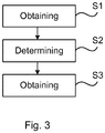
Fig. 3 is a flowchart of a method of determining a temperature distribution in a mould plate. - The inventive concept will now be described more fully hereinafter with reference to the accompanying drawings, in which exemplifying embodiments are shown. The inventive concept may, however, be embodied in many different forms and should not be construed as limited to the embodiments set forth herein; rather, these embodiments are provided by way of example so that this disclosure will be thorough and complete, and will fully convey the scope of the inventive concept to those skilled in the art. Like numbers refer to like elements throughout the description.
-
Fig. 1 shows an example of a temperature calculatingdevice 1 for determining a temperature distribution in a mould plate of a mould for a metal-making process. Such a metal-making process is typically a continuous casting process, for example for steelmaking, aluminium, copper or lead-making. - The
temperature calculating device 1 comprisesprocessing circuitry 3 and astorage medium 5. Thestorage medium 5 comprises computer code which when executed by theprocessing circuitry 3 causes thetemperature calculating device 1 to perform the methods disclosed herein. - The
processing circuitry 3 uses any combination of one or more of a suitable central processing unit (CPU), multiprocessor, microcontroller, programmable logic controller (PLC), digital signal processor (DSP), application specific integrated circuit (ASIC), field programmable gate arrays (FPGA) etc., capable of executing any herein disclosed operations concerning temperature distribution calculations. - The
storage medium 5 may for example be embodied as a memory, such as a random-access memory (RAM), a read-only memory (ROM), an erasable programmable read-only memory (EPROM), or an electrically erasable programmable read-only memory (EEPROM) and more particularly as a non-volatile storage medium of a device in an external memory such as a USB (Universal Serial Bus) memory or a Flash memory, such as a compact Flash memory. -
Fig. 2a shows a section through amould plate 7 having a hot face H configured to face molten metal M. It may be noted that during regular casting conditions, the mould plate and the molten metal are typically separated by a thin layer of lubricating mould flux. Themould plate 7 is configured to be cooled by a coolant. To this end, the mould plate comprises a plurality of cooling slots in which the coolant is able to flow to cool themould plate 7 and thus the molten metal M. The coolant is typically water, and the cooling slots are in this case water cooling slots. For reasons of clarity, the cooling slots have been omitted inFig. 2a . - The
mould plate 7 comprises a plurality oftemperature sensors 9a-9n, at least part of which may not have a placement in the mould plate where the heat transfer direction is linearly aligned with the normal direction to the mould plate hot surface. At least part of thetemperature sensors 9a-9n may not have a symmetric placement in respective of adjacent cooling channels, or at least part of the temperature sensors must be positioned above the molten metal level or close to adjacent mould plates, or at least part of the temperature sensors are located in regions of mould plate topological complexities such as curvature, chamfered edges or corners. - Each
temperature sensor 9a-9n is configured to detect a temperature in themould plate 7 at the location where it is installed in themould plate 7. In this manner a plurality of temperature values in themould plate 7 may be obtained from thetemperature sensors 9a-9n. - Each
temperature sensor 9a-9n is associated with coordinates in a coordinate system defined by the three axes x, y, and z shown inFigs 2a and 2b , z typically being the vertical axis. The location of eachtemperature sensor 9a-9n in the coordinate system is defined by its coordinates. The coordinates of a temperature sensor 9k has coordinates in the form (x9k, y9k, z9k). The temperature value measured by atemperature sensor 9a-9n is the temperature at the location of thetemperature sensor 9a-9n in question. - Each
temperature sensor 9a-9n is associated with arespective reference point 13a-13n located in the coordinate system in themould plate 7. For example,temperature sensor 9a is associated with thereference point 13a andtemperature sensor 9b is associated with thereference point 13b. Thereference points 13a-13n may be any points located in themould plate 7, spaced apart from thetemperature sensors 9a-9n. Thereference points 13a-13n are typically located close to or on the hot face H of themould plate 7 in order to be able to obtain a temperature estimation at the hot face H. - According to the present example, each
temperature sensor 9a-9n is a fibre optical sensor but they could alternatively be for example thermocouples. Themould plate 7 comprises a plurality ofoptical fibres 11j-11r extending from one end of themould plate 7 to an opposite end thereof. Eachoptical fibre 11j-11r comprises a plurality oftemperature sensors 9a-9n, e.g. FBGs, distributed along the longitudinal direction of theoptical fibre 11j-11r. In this manner a dense grid, or matrix, oftemperature sensors 9a-9n may be obtained in the x-z plane. In the section depicted inFig. 2a , only one suchoptical fibre 11j is shown, whileFig. 2b shows a plurality ofoptical fibres 11j-11r distributed along the x-axis of themould plate 7, extending longitudinally along the z-axis. - The present method enables the estimation of the temperature at the
reference points 13a-13n based on the temperature values obtained from thetemperature sensors 9a-9n as will be explained in the following. - In a step Si the
temperature calculating device 1 obtains temperature values from each of the plurality ofsensors 9a-9n arranged in themould plate 7, typically from a plurality of theoptical fibres 11j-11r distributed in themould plate 7 along the x-axis. - In a step S2, a reference point temperature value is determined for each temperature value obtained from the
temperature sensors 9a-9n in step Si. This reference point temperature value for each temperature value is determined by means of either a respective linear function or a respective non-linear function. Either the linear function or the non-linear function describes a temperature relationship between the corresponding temperature value and an estimated temperature at the corresponding reference point. As an example, when a temperature value T9a is obtained from thetemperature sensor 9a, the corresponding function transforms the temperature value T9a to a reference point temperature value T13a, which is the estimated temperature at thereference point 13a. The estimated temperature may be obtained by simulation. - The linear function may be expressed as shown in equation (1) below.

- Alternatively, a general non-linear function formulation may be used to describe a temperature relationship between the temperature value obtained from a temperature sensor and an estimated temperature at the corresponding reference point. This general formulation may be expressed as in equation (2) below,

- As an example, such a non-linear function may be formulated as a polynomial Taylor expansion as in equation (3) below,

- Thus, in step S2, when a linear function as expressed in equation (1) is used, each reference point temperature value is determined using the corresponding function f9i by multiplying the correction factor with the corresponding temperature value to obtain a product and add the correction term. The correction factor and correction term for each reference point is extracted by the
processing circuitry 3 from thestorage medium 5; while when a general non-linear function expressed in equation (2) is used, each reference point temperature value is determined by using a set of parameters dl . The constant parameters are extracted by theprocessing circuitry 3 from thestorage medium 5. When the general non-linear function being presented as a non-linear polynomial function expressed in equation (3) is used, each reference point temperature value is determined by using a set of higher-order correction coefficients c9i,k. The correction coefficients are extracted by theprocessing circuitry 3 from thestorage medium 5. In this manner the reference point temperature values, which are estimations of the temperature at the reference points, are obtained. - In a step S3, an estimated temperature distribution at the
reference points 13a-13n is obtained by means of the reference point temperature values T13i. The temperature distribution provides for each reference point a reference point temperature value. This temperature distribution may as an example be presented visually on a display or used for further data analysis. - By means of the presented method, an online three-dimensional temperature distribution in the
mould plate 7 may be obtained. In particular, if thereference points 13a-13n are selected to be at the hot face H, an estimation of the temperature distribution at the hot face may be obtained. In case the density of the grid formed by thetemperature sensors 9a-9n in the plurality ofoptical fibres 11j-11r, is selected to be high enough, a high-resolution temperature distribution in themould plate 7 can be obtained. - Taking the linear function of equation (1) as an example, the functions f9i which transform the temperature values measured by the
temperature sensors 9a-9n can be determined as follows. - The thermal asymmetry and the non-perpendicular heat flux directions in the
mould plate 7 can be determined based on a model of themould plate 7. Determination of the thermal asymmetry and the non-perpendicular heat flux may in particular involve solving partial differential equations for heat transfer in solid media with boundary conditions of the cooling slots and an ideal homogeneous heat profile of the hot face of the mould plate. An estimated heat distribution in themould plate 7 may in this manner be obtained in three dimensions for a certain mould plate condition. An initial temperature relationship between a simulated temperature at each temperature sensor and the corresponding reference points may in this manner be obtained for the mould plate condition in question. For example, if a simulation of the model, using a specific mould plate condition of a homogeneously distributed temperature over the hot face of the mould plate, a cooling water temperature and heat transfer coefficient as boundary condition for the mould-water interfaces, and heat transfer coefficients between the mould and the ambient materials for the rest of the mould surfaces, results in a simulated temperature of T9i = 250 °C at the location of a temperature sensor and a simulated temperature of T13i = 500 °C for the corresponding reference point, there will be two unknown constants in equation (1) associated with eachtemperature sensor 9a-9n, with T9i and T13i being known. These unknown constants are the corresponding correction factor c9i and correction term d9i. By using at least two different unique mould plate thermal conditions, and simulating for each case, a respective equation system associated with eachtemperature sensor 9a-9n can be obtained, each containing at least two initial temperature relationships. Solving each such equation system, the correction factor c9i and the correction term d9i associated with thetemperature sensors 9a-9n may be obtained, which reflect the three-dimensional temperature distribution, non-perpendicular heat transfer and/or the thermal asymmetry of themould plate 7, and the temperature relationships in equation (1) are hence obtained with each c9i and d9i being known. In this manner, the reference point temperature values may be determined in step S2 as previously explained. Thus, the present invention may not be limited to one-dimensional heat transfer perpendicular to the mould plate hot surface. This non-perpendicular heat transfer at the sensing points may be caused by the asymmetrical placement of the fibre optical sensors, a non-flat mould plate within a particular area of the plate, a non-homogeneous cooling channel arrangement at the back end of the mould plate, placement of the temperature sensors above the molten metal level or close to adjacent mould plates or corners, which thus results in a non-perpendicular heat transfer direction. - A similar principle is applicable to the case of a polynomial or general non-linear function.
- The
temperature calculating device 1 may be utilised in a system which comprises thetemperature calculating device 1 and a plurality oftemperature sensors 9a-9n, in particular a plurality of fibre optical sensors configured to be arranged in a mould plate, the fibre optical sensors may be for example any of the types Fibre Bragg grating (FBG) sensors, interferometric fibre sensors, optical fibre polarimetric sensors, fibre optic micro bend sensors, distributed fibre optic sensors in either the time or frequency domain based on Raman, Brillouin or Rayleigh scattering.
Claims (14)
- A method of determining a temperature distribution in a mould plate (7) of a mould for a metal-making process, wherein the method comprises:obtaining (S1) a temperature value from each of a plurality of temperature sensors (9a-9n) arranged in the mould plate, each temperature sensor (9a-9n) being a sensing point and being spaced apart from a respective reference point (13a-13n) in the mould plate (7),for each of the sensing points, obtaining, from a plurality of initial temperature relationships, the correction factor and correction term of a linear function or a set of parameters in a general non-linear formulation of a non-linear function, wherein each initial temperature relationship is between a simulated temperature at the corresponding temperature sensor in the mould plate and a simulated temperature at a corresponding reference point (13a-13n) in the mould plate, each simulated temperature being obtained based on a respective simulation of a model of the mould plate (7) for a unique thermal mould plate condition wherein the thermal boundary conditions of the mould plate have been completely, explicitly and uniquely stated,determining (S2) for each temperature value the reference point temperature value at the corresponding reference point (13a-13n) using either the respective linear function or the respective non-linear function, andobtaining (S3) an estimated temperature distribution at the reference points (13a-13n) in the mould plate (7) by means of the reference point temperature values.
- The method as claimed in claim 1, wherein the correction factor and the correction term of the linear function is unique for the temperature sensor (9a-9n) in question.
- The method as claimed in claim 2, wherein the correction factor is a first constant which is multiplied with the corresponding temperature value to obtain a product and the correction term is a second constant added to the product.
- The method as claimed in claim 1, wherein the set of parameters of the general non-linear function is unique for the temperature sensor (9a-9n) in question.
- The method as claimed in claim 1, wherein the general non-linear formulation of the non-linear function is a non-linear function polynomial expansion and the set of correction coefficients of the non-linear function polynomial expansion is unique for the temperature sensor (9a-9n) in question.
- The method as claimed in any of the preceding claims, wherein each reference point (13a-13n) is a point on the hot face (7a) of the mould plate (7).
- The method as claimed in any of the preceding claims, wherein each temperature sensor (9a-9n) is a fibre optical sensor.
- The method as claimed in claim 7, wherein the fibre optical sensor is any kind of Fibre Bragg grating (FBG) sensor, interferometric fibre sensor, optical fibre polarimetric sensor, fibre optic micro bend sensor, distributed fibre optic sensor in either the time or frequency domain based on Raman, Brillouin or Rayleigh scattering.
- The method as claimed in any of the preceding claims, wherein the unique thermal mould plate condition is of homogeneously distributed temperature over the hot face of the mould plate, a cooling water temperature and heat transfer coefficient as boundary condition for the mould-water interfaces, and heat transfer coefficients between the mould and the ambient materials for the rest of the mould surfaces.
- A computer program comprising computer-executable code which when executed by a temperature calculating device (1) performs the method as claimed in any of claims 1-9.
- A computer program product comprising a storage medium (5) provided with the computer program of claim 10.
- A temperature calculating device (1) for determining a temperature distribution in a mould plate (7) of a mould for a metal-making process, wherein the temperature calculating device (1) comprises:processing circuitry (3), anda storage medium (5) comprising computer-executable code which when executed by the processing circuitry (3) causes the temperature calculating device (1) to perform method steps of claims 1 to 9.
- A system for determining a temperature distribution in a mould plate (7) of a mould for a metal-making process, wherein the system comprises:a temperature calculating device (1) as claimed in claim 12, anda plurality of fibre optical sensors (9a-9n) configured to be arranged in the mould plate (7) and configured to provide temperature values concerning the temperature in the mould plate (7) to the temperature calculating device (1).
- The system as claimed in claim 13, wherein the fibre optical sensor is any kind of Fibre Bragg grating (FBG) sensor, interferometric fibre sensor, optical fibre polarimetric sensor, fibre optic micro bend sensor, distributed fibre optic sensor in either the time or frequency domain based on Raman, Brillouin or Rayleigh scattering.
Applications Claiming Priority (2)
| Application Number | Priority Date | Filing Date | Title |
|---|---|---|---|
| EP17161984.4A EP3379217A1 (en) | 2017-03-21 | 2017-03-21 | Method and device for determining a temperature distribution in a mould plate for a metal-making process |
| PCT/EP2018/056101 WO2018172124A1 (en) | 2017-03-21 | 2018-03-12 | Method and device for determining a temperature distribution in a mould plate for a metal-making process |
Publications (2)
| Publication Number | Publication Date |
|---|---|
| EP3601969A1 EP3601969A1 (en) | 2020-02-05 |
| EP3601969B1 true EP3601969B1 (en) | 2021-05-05 |
Family
ID=58398073
Family Applications (2)
| Application Number | Title | Priority Date | Filing Date |
|---|---|---|---|
| EP17161984.4A Withdrawn EP3379217A1 (en) | 2017-03-21 | 2017-03-21 | Method and device for determining a temperature distribution in a mould plate for a metal-making process |
| EP18709360.4A Active EP3601969B1 (en) | 2017-03-21 | 2018-03-12 | Method and device for determining a temperature distribution in a mould plate for a metal-making process |
Family Applications Before (1)
| Application Number | Title | Priority Date | Filing Date |
|---|---|---|---|
| EP17161984.4A Withdrawn EP3379217A1 (en) | 2017-03-21 | 2017-03-21 | Method and device for determining a temperature distribution in a mould plate for a metal-making process |
Country Status (6)
| Country | Link |
|---|---|
| US (1) | US10974314B2 (en) |
| EP (2) | EP3379217A1 (en) |
| JP (1) | JP6688942B2 (en) |
| KR (1) | KR102077440B1 (en) |
| CN (1) | CN110446911B (en) |
| WO (1) | WO2018172124A1 (en) |
Families Citing this family (1)
| Publication number | Priority date | Publication date | Assignee | Title |
|---|---|---|---|---|
| EP4684895A1 (en) * | 2025-07-07 | 2026-01-28 | Primetals Technologies Austria GmbH | Method for determining the installation heights of horizontally oriented optical fiber sensors in a continuous casting mold and a correspondent data model, method for continuous casting and continuous casting mold |
Family Cites Families (18)
| Publication number | Priority date | Publication date | Assignee | Title |
|---|---|---|---|---|
| JPH0446658A (en) * | 1990-06-12 | 1992-02-17 | Toshiba Corp | Device for predicting breakout in continuous casting apparatus |
| US6142662A (en) * | 1998-06-16 | 2000-11-07 | New Jersey Institute Of Technology | Apparatus and method for simultaneously determining thermal conductivity and thermal contact resistance |
| US20060182832A1 (en) | 2005-02-17 | 2006-08-17 | Sif Universal Pte Ltd | Semiconductor molding temperature and pressure sensors |
| JP4579820B2 (en) * | 2005-12-19 | 2010-11-10 | 新日本製鐵株式会社 | Apparatus and method for determining operating state of mold or mold operating surface, method for operating mold or mold, computer program, and computer-readable recording medium |
| DE102008003962B4 (en) * | 2007-01-12 | 2013-10-17 | Nissan Motor Co., Ltd. | Solidification analysis method and apparatus |
| DE102008029742A1 (en) | 2008-06-25 | 2009-12-31 | Sms Siemag Aktiengesellschaft | Mold for casting metal |
| JP4914429B2 (en) * | 2008-12-05 | 2012-04-11 | 株式会社豊田中央研究所 | Solidification analysis method and solidification analysis program for molten alloy |
| ES2372829B1 (en) * | 2009-02-24 | 2012-12-13 | Daniel Gaude Fugarolas | PROCEDURE FOR REDUCTION OF INTERSTICIAL ELEMENTS IN ALLOY LAYER AND MOLD FOR THE PERFORMANCE OF THIS PROCEDURE. |
| FR2945118B1 (en) * | 2009-04-29 | 2011-06-17 | Avemis | SENSOR AND METHOD FOR MEASURING THE LEVEL OF THE SURFACE OF A LIQUID PHASE METAL |
| US8974952B2 (en) | 2009-10-13 | 2015-03-10 | Samsung Sdi Co., Ltd. | Rechargeable battery |
| US20110144790A1 (en) * | 2009-12-15 | 2011-06-16 | Terry Gerritsen | Thermal Sensing for Material Processing Assemblies |
| DE102011085932A1 (en) | 2011-06-07 | 2012-12-13 | Sms Siemag Ag | Method for regulating the height of the casting mirror in a mold of a continuous casting plant |
| JP6381868B2 (en) * | 2013-01-25 | 2018-08-29 | 株式会社神戸製鋼所 | Continuous casting method of ingot made of titanium or titanium alloy |
| CN106413942B (en) * | 2014-01-31 | 2020-03-10 | 日本制铁株式会社 | Method, device and program for judging casting state of continuous casting |
| US20150343530A1 (en) * | 2014-05-30 | 2015-12-03 | Elwha Llc | Systems and methods for monitoring castings |
| JP6515329B2 (en) * | 2015-04-08 | 2019-05-22 | 日本製鉄株式会社 | Continuous casting mold |
| WO2017032392A1 (en) * | 2015-08-21 | 2017-03-02 | Abb Schweiz Ag | A casting mold and a method for measuring temperature of a casting mold |
| CN105880501B (en) * | 2016-06-03 | 2018-02-23 | 中南大学 | A kind of method of covering slag and crystallizer interface resistance in measurement continuous cast mold |
-
2017
- 2017-03-21 EP EP17161984.4A patent/EP3379217A1/en not_active Withdrawn
-
2018
- 2018-03-12 US US16/496,307 patent/US10974314B2/en active Active
- 2018-03-12 JP JP2019551930A patent/JP6688942B2/en active Active
- 2018-03-12 WO PCT/EP2018/056101 patent/WO2018172124A1/en not_active Ceased
- 2018-03-12 EP EP18709360.4A patent/EP3601969B1/en active Active
- 2018-03-12 KR KR1020197030769A patent/KR102077440B1/en active Active
- 2018-03-12 CN CN201880019937.XA patent/CN110446911B/en active Active
Also Published As
| Publication number | Publication date |
|---|---|
| CN110446911B (en) | 2020-11-03 |
| EP3379217A1 (en) | 2018-09-26 |
| WO2018172124A1 (en) | 2018-09-27 |
| EP3601969A1 (en) | 2020-02-05 |
| JP2020511660A (en) | 2020-04-16 |
| CN110446911A (en) | 2019-11-12 |
| KR102077440B1 (en) | 2020-02-13 |
| JP6688942B2 (en) | 2020-04-28 |
| US10974314B2 (en) | 2021-04-13 |
| KR20190126166A (en) | 2019-11-08 |
| US20210039159A1 (en) | 2021-02-11 |
Similar Documents
| Publication | Publication Date | Title |
|---|---|---|
| CN107921527B (en) | Casting mold and method for detecting temperature distribution of molten metal in casting mold | |
| JP5505086B2 (en) | Method, apparatus and program for estimating state in mold in continuous casting | |
| JP5387508B2 (en) | Continuous casting method, continuous casting control device and program | |
| Lieftucht et al. | HD mold—A new fiber-optical-based mold monitoring system | |
| Balogun et al. | Shell measurements and mold thermal mapping approach to characterize steel shell formation in peritectic grade steels | |
| US20170232505A1 (en) | Apparatus, method, and program for detecting molten metal surface level in continuous casting mold | |
| US10974314B2 (en) | Method and device for determining a temperature distribution in a mold plate for a metal-making process | |
| Zappulla et al. | Simulation of longitudinal surface defect in steel continuous casting | |
| JP5408040B2 (en) | Continuous casting method, continuous casting control device and program | |
| CN115128124A (en) | Casting equipment and method for measuring interface heat exchange coefficient by adopting same | |
| EP4372301B1 (en) | Method for monitoring the wear of a refractory lining of a blast furnace | |
| Hedin et al. | Exploring opportunities in mold temperature monitoring utilizing Fiber Bragg Gratings | |
| JP4828366B2 (en) | Longitudinal detection method and continuous casting method based on mold heat flux | |
| JP7135728B2 (en) | Slab Quality Estimating Method, Steel Manufacturing Method, Slab Quality Estimating Device, and Program | |
| JP2016065811A (en) | Device and method for measuring temperature | |
| Balogun | Peritectic Behavior Detection and Prediction in Fe-C-Si-Mn-Al System | |
| EP4442387A1 (en) | Continuous casting start timing determination method, continuous casting facility operation method, slab manufacturing method, determining device, continuous casting start determination system, and display terminal device | |
| KR970033269A (en) | How to measure cast iron defects in continuous casting of steel small section billet | |
| JP5387506B2 (en) | Continuous casting method, continuous casting control device and program | |
| Balogun et al. | A Fiber-Optic-Distributed Temperature Mapping Technique to Characterize Shell Solidification in Peritectic-Grade Steels | |
| KR20160037527A (en) | Casting apparatus and visualization method for meniscus | |
| Woolley et al. | Aluminum Sand Casting Interfacial Heat Flux Estimation Based on Corrected Temperature Measurements | |
| Woodbury et al. | Relationship between casting distortion, mold filling, and interfacial heat transfer. Annual technical report, September 1997-September 1998 |
Legal Events
| Date | Code | Title | Description |
|---|---|---|---|
| STAA | Information on the status of an ep patent application or granted ep patent |
Free format text: STATUS: UNKNOWN |
|
| STAA | Information on the status of an ep patent application or granted ep patent |
Free format text: STATUS: THE INTERNATIONAL PUBLICATION HAS BEEN MADE |
|
| PUAI | Public reference made under article 153(3) epc to a published international application that has entered the european phase |
Free format text: ORIGINAL CODE: 0009012 |
|
| STAA | Information on the status of an ep patent application or granted ep patent |
Free format text: STATUS: REQUEST FOR EXAMINATION WAS MADE |
|
| 17P | Request for examination filed |
Effective date: 20191003 |
|
| AK | Designated contracting states |
Kind code of ref document: A1 Designated state(s): AL AT BE BG CH CY CZ DE DK EE ES FI FR GB GR HR HU IE IS IT LI LT LU LV MC MK MT NL NO PL PT RO RS SE SI SK SM TR |
|
| AX | Request for extension of the european patent |
Extension state: BA ME |
|
| DAV | Request for validation of the european patent (deleted) | ||
| DAX | Request for extension of the european patent (deleted) | ||
| GRAP | Despatch of communication of intention to grant a patent |
Free format text: ORIGINAL CODE: EPIDOSNIGR1 |
|
| STAA | Information on the status of an ep patent application or granted ep patent |
Free format text: STATUS: GRANT OF PATENT IS INTENDED |
|
| INTG | Intention to grant announced |
Effective date: 20201105 |
|
| GRAS | Grant fee paid |
Free format text: ORIGINAL CODE: EPIDOSNIGR3 |
|
| RAP1 | Party data changed (applicant data changed or rights of an application transferred) |
Owner name: ABB SCHWEIZ AG |
|
| GRAA | (expected) grant |
Free format text: ORIGINAL CODE: 0009210 |
|
| STAA | Information on the status of an ep patent application or granted ep patent |
Free format text: STATUS: THE PATENT HAS BEEN GRANTED |
|
| AK | Designated contracting states |
Kind code of ref document: B1 Designated state(s): AL AT BE BG CH CY CZ DE DK EE ES FI FR GB GR HR HU IE IS IT LI LT LU LV MC MK MT NL NO PL PT RO RS SE SI SK SM TR |
|
| REG | Reference to a national code |
Ref country code: GB Ref legal event code: FG4D |
|
| REG | Reference to a national code |
Ref country code: CH Ref legal event code: EP |
|
| REG | Reference to a national code |
Ref country code: AT Ref legal event code: REF Ref document number: 1390391 Country of ref document: AT Kind code of ref document: T Effective date: 20210515 |
|
| REG | Reference to a national code |
Ref country code: IE Ref legal event code: FG4D |
|
| REG | Reference to a national code |
Ref country code: DE Ref legal event code: R096 Ref document number: 602018016628 Country of ref document: DE |
|
| REG | Reference to a national code |
Ref country code: NL Ref legal event code: FP |
|
| REG | Reference to a national code |
Ref country code: LT Ref legal event code: MG9D |
|
| PG25 | Lapsed in a contracting state [announced via postgrant information from national office to epo] |
Ref country code: FI Free format text: LAPSE BECAUSE OF FAILURE TO SUBMIT A TRANSLATION OF THE DESCRIPTION OR TO PAY THE FEE WITHIN THE PRESCRIBED TIME-LIMIT Effective date: 20210505 Ref country code: HR Free format text: LAPSE BECAUSE OF FAILURE TO SUBMIT A TRANSLATION OF THE DESCRIPTION OR TO PAY THE FEE WITHIN THE PRESCRIBED TIME-LIMIT Effective date: 20210505 Ref country code: LT Free format text: LAPSE BECAUSE OF FAILURE TO SUBMIT A TRANSLATION OF THE DESCRIPTION OR TO PAY THE FEE WITHIN THE PRESCRIBED TIME-LIMIT Effective date: 20210505 Ref country code: BG Free format text: LAPSE BECAUSE OF FAILURE TO SUBMIT A TRANSLATION OF THE DESCRIPTION OR TO PAY THE FEE WITHIN THE PRESCRIBED TIME-LIMIT Effective date: 20210805 |
|
| PG25 | Lapsed in a contracting state [announced via postgrant information from national office to epo] |
Ref country code: GR Free format text: LAPSE BECAUSE OF FAILURE TO SUBMIT A TRANSLATION OF THE DESCRIPTION OR TO PAY THE FEE WITHIN THE PRESCRIBED TIME-LIMIT Effective date: 20210806 Ref country code: IS Free format text: LAPSE BECAUSE OF FAILURE TO SUBMIT A TRANSLATION OF THE DESCRIPTION OR TO PAY THE FEE WITHIN THE PRESCRIBED TIME-LIMIT Effective date: 20210905 Ref country code: NO Free format text: LAPSE BECAUSE OF FAILURE TO SUBMIT A TRANSLATION OF THE DESCRIPTION OR TO PAY THE FEE WITHIN THE PRESCRIBED TIME-LIMIT Effective date: 20210805 Ref country code: LV Free format text: LAPSE BECAUSE OF FAILURE TO SUBMIT A TRANSLATION OF THE DESCRIPTION OR TO PAY THE FEE WITHIN THE PRESCRIBED TIME-LIMIT Effective date: 20210505 Ref country code: PL Free format text: LAPSE BECAUSE OF FAILURE TO SUBMIT A TRANSLATION OF THE DESCRIPTION OR TO PAY THE FEE WITHIN THE PRESCRIBED TIME-LIMIT Effective date: 20210505 Ref country code: PT Free format text: LAPSE BECAUSE OF FAILURE TO SUBMIT A TRANSLATION OF THE DESCRIPTION OR TO PAY THE FEE WITHIN THE PRESCRIBED TIME-LIMIT Effective date: 20210906 Ref country code: RS Free format text: LAPSE BECAUSE OF FAILURE TO SUBMIT A TRANSLATION OF THE DESCRIPTION OR TO PAY THE FEE WITHIN THE PRESCRIBED TIME-LIMIT Effective date: 20210505 Ref country code: SE Free format text: LAPSE BECAUSE OF FAILURE TO SUBMIT A TRANSLATION OF THE DESCRIPTION OR TO PAY THE FEE WITHIN THE PRESCRIBED TIME-LIMIT Effective date: 20210505 |
|
| REG | Reference to a national code |
Ref country code: AT Ref legal event code: UEP Ref document number: 1390391 Country of ref document: AT Kind code of ref document: T Effective date: 20210505 |
|
| PG25 | Lapsed in a contracting state [announced via postgrant information from national office to epo] |
Ref country code: SK Free format text: LAPSE BECAUSE OF FAILURE TO SUBMIT A TRANSLATION OF THE DESCRIPTION OR TO PAY THE FEE WITHIN THE PRESCRIBED TIME-LIMIT Effective date: 20210505 Ref country code: SM Free format text: LAPSE BECAUSE OF FAILURE TO SUBMIT A TRANSLATION OF THE DESCRIPTION OR TO PAY THE FEE WITHIN THE PRESCRIBED TIME-LIMIT Effective date: 20210505 Ref country code: ES Free format text: LAPSE BECAUSE OF FAILURE TO SUBMIT A TRANSLATION OF THE DESCRIPTION OR TO PAY THE FEE WITHIN THE PRESCRIBED TIME-LIMIT Effective date: 20210505 Ref country code: EE Free format text: LAPSE BECAUSE OF FAILURE TO SUBMIT A TRANSLATION OF THE DESCRIPTION OR TO PAY THE FEE WITHIN THE PRESCRIBED TIME-LIMIT Effective date: 20210505 Ref country code: RO Free format text: LAPSE BECAUSE OF FAILURE TO SUBMIT A TRANSLATION OF THE DESCRIPTION OR TO PAY THE FEE WITHIN THE PRESCRIBED TIME-LIMIT Effective date: 20210505 Ref country code: DK Free format text: LAPSE BECAUSE OF FAILURE TO SUBMIT A TRANSLATION OF THE DESCRIPTION OR TO PAY THE FEE WITHIN THE PRESCRIBED TIME-LIMIT Effective date: 20210505 Ref country code: CZ Free format text: LAPSE BECAUSE OF FAILURE TO SUBMIT A TRANSLATION OF THE DESCRIPTION OR TO PAY THE FEE WITHIN THE PRESCRIBED TIME-LIMIT Effective date: 20210505 |
|
| REG | Reference to a national code |
Ref country code: DE Ref legal event code: R097 Ref document number: 602018016628 Country of ref document: DE |
|
| PLBE | No opposition filed within time limit |
Free format text: ORIGINAL CODE: 0009261 |
|
| STAA | Information on the status of an ep patent application or granted ep patent |
Free format text: STATUS: NO OPPOSITION FILED WITHIN TIME LIMIT |
|
| 26N | No opposition filed |
Effective date: 20220208 |
|
| PG25 | Lapsed in a contracting state [announced via postgrant information from national office to epo] |
Ref country code: IS Free format text: LAPSE BECAUSE OF FAILURE TO SUBMIT A TRANSLATION OF THE DESCRIPTION OR TO PAY THE FEE WITHIN THE PRESCRIBED TIME-LIMIT Effective date: 20210905 Ref country code: AL Free format text: LAPSE BECAUSE OF FAILURE TO SUBMIT A TRANSLATION OF THE DESCRIPTION OR TO PAY THE FEE WITHIN THE PRESCRIBED TIME-LIMIT Effective date: 20210505 |
|
| PG25 | Lapsed in a contracting state [announced via postgrant information from national office to epo] |
Ref country code: MC Free format text: LAPSE BECAUSE OF FAILURE TO SUBMIT A TRANSLATION OF THE DESCRIPTION OR TO PAY THE FEE WITHIN THE PRESCRIBED TIME-LIMIT Effective date: 20210505 |
|
| REG | Reference to a national code |
Ref country code: CH Ref legal event code: PL |
|
| REG | Reference to a national code |
Ref country code: BE Ref legal event code: MM Effective date: 20220331 |
|
| PG25 | Lapsed in a contracting state [announced via postgrant information from national office to epo] |
Ref country code: LU Free format text: LAPSE BECAUSE OF NON-PAYMENT OF DUE FEES Effective date: 20220312 Ref country code: LI Free format text: LAPSE BECAUSE OF NON-PAYMENT OF DUE FEES Effective date: 20220331 Ref country code: IE Free format text: LAPSE BECAUSE OF NON-PAYMENT OF DUE FEES Effective date: 20220312 Ref country code: FR Free format text: LAPSE BECAUSE OF NON-PAYMENT OF DUE FEES Effective date: 20220331 Ref country code: CH Free format text: LAPSE BECAUSE OF NON-PAYMENT OF DUE FEES Effective date: 20220331 |
|
| PG25 | Lapsed in a contracting state [announced via postgrant information from national office to epo] |
Ref country code: BE Free format text: LAPSE BECAUSE OF NON-PAYMENT OF DUE FEES Effective date: 20220331 |
|
| PG25 | Lapsed in a contracting state [announced via postgrant information from national office to epo] |
Ref country code: MK Free format text: LAPSE BECAUSE OF FAILURE TO SUBMIT A TRANSLATION OF THE DESCRIPTION OR TO PAY THE FEE WITHIN THE PRESCRIBED TIME-LIMIT Effective date: 20210505 Ref country code: CY Free format text: LAPSE BECAUSE OF FAILURE TO SUBMIT A TRANSLATION OF THE DESCRIPTION OR TO PAY THE FEE WITHIN THE PRESCRIBED TIME-LIMIT Effective date: 20210505 |
|
| PG25 | Lapsed in a contracting state [announced via postgrant information from national office to epo] |
Ref country code: HU Free format text: LAPSE BECAUSE OF FAILURE TO SUBMIT A TRANSLATION OF THE DESCRIPTION OR TO PAY THE FEE WITHIN THE PRESCRIBED TIME-LIMIT; INVALID AB INITIO Effective date: 20180312 |
|
| PG25 | Lapsed in a contracting state [announced via postgrant information from national office to epo] |
Ref country code: MT Free format text: LAPSE BECAUSE OF FAILURE TO SUBMIT A TRANSLATION OF THE DESCRIPTION OR TO PAY THE FEE WITHIN THE PRESCRIBED TIME-LIMIT Effective date: 20210505 |
|
| PG25 | Lapsed in a contracting state [announced via postgrant information from national office to epo] |
Ref country code: TR Free format text: LAPSE BECAUSE OF FAILURE TO SUBMIT A TRANSLATION OF THE DESCRIPTION OR TO PAY THE FEE WITHIN THE PRESCRIBED TIME-LIMIT Effective date: 20210505 |
|
| PGFP | Annual fee paid to national office [announced via postgrant information from national office to epo] |
Ref country code: GB Payment date: 20260324 Year of fee payment: 9 |
|
| PGFP | Annual fee paid to national office [announced via postgrant information from national office to epo] |
Ref country code: DE Payment date: 20260319 Year of fee payment: 9 |
|
| PGFP | Annual fee paid to national office [announced via postgrant information from national office to epo] |
Ref country code: AT Payment date: 20260320 Year of fee payment: 9 |
|
| PGFP | Annual fee paid to national office [announced via postgrant information from national office to epo] |
Ref country code: IT Payment date: 20260324 Year of fee payment: 9 |
|
| PGFP | Annual fee paid to national office [announced via postgrant information from national office to epo] |
Ref country code: NL Payment date: 20260319 Year of fee payment: 9 |