EP3600996B1 - Integriertes anhängersteuermodul (tcv) mit externer elektropneumatischer handbremseinheit (eph) - Google Patents
Integriertes anhängersteuermodul (tcv) mit externer elektropneumatischer handbremseinheit (eph) Download PDFInfo
- Publication number
- EP3600996B1 EP3600996B1 EP18715524.7A EP18715524A EP3600996B1 EP 3600996 B1 EP3600996 B1 EP 3600996B1 EP 18715524 A EP18715524 A EP 18715524A EP 3600996 B1 EP3600996 B1 EP 3600996B1
- Authority
- EP
- European Patent Office
- Prior art keywords
- pressure
- brake
- valve
- trailer
- control
- Prior art date
- Legal status (The legal status is an assumption and is not a legal conclusion. Google has not performed a legal analysis and makes no representation as to the accuracy of the status listed.)
- Active
Links
- 238000011144 upstream manufacturing Methods 0.000 claims description 3
- 230000003100 immobilizing effect Effects 0.000 claims 10
- 238000012544 monitoring process Methods 0.000 claims 3
- 230000001419 dependent effect Effects 0.000 claims 1
- 238000013022 venting Methods 0.000 description 7
- 230000008901 benefit Effects 0.000 description 5
- 230000008878 coupling Effects 0.000 description 5
- 238000010168 coupling process Methods 0.000 description 5
- 238000005859 coupling reaction Methods 0.000 description 5
- 230000010354 integration Effects 0.000 description 5
- 238000013459 approach Methods 0.000 description 4
- 238000011161 development Methods 0.000 description 4
- 238000010276 construction Methods 0.000 description 3
- 238000013461 design Methods 0.000 description 3
- 238000002360 preparation method Methods 0.000 description 3
- 230000007423 decrease Effects 0.000 description 2
- 238000001514 detection method Methods 0.000 description 2
- 238000005259 measurement Methods 0.000 description 2
- 238000003825 pressing Methods 0.000 description 2
- 241000310247 Amyna axis Species 0.000 description 1
- 238000007792 addition Methods 0.000 description 1
- 230000033228 biological regulation Effects 0.000 description 1
- 238000009530 blood pressure measurement Methods 0.000 description 1
- 230000008859 change Effects 0.000 description 1
- 238000004891 communication Methods 0.000 description 1
- 230000037406 food intake Effects 0.000 description 1
- 238000009434 installation Methods 0.000 description 1
- 230000003993 interaction Effects 0.000 description 1
- 230000002452 interceptive effect Effects 0.000 description 1
- 230000007246 mechanism Effects 0.000 description 1
- RXQCGGRTAILOIN-UHFFFAOYSA-N mephentermine Chemical compound CNC(C)(C)CC1=CC=CC=C1 RXQCGGRTAILOIN-UHFFFAOYSA-N 0.000 description 1
- 229960002342 mephentermine Drugs 0.000 description 1
- 238000000034 method Methods 0.000 description 1
- 238000012986 modification Methods 0.000 description 1
- 230000004048 modification Effects 0.000 description 1
- 230000002093 peripheral effect Effects 0.000 description 1
- 238000007639 printing Methods 0.000 description 1
- 230000008569 process Effects 0.000 description 1
- 230000003584 silencer Effects 0.000 description 1
- 239000000725 suspension Substances 0.000 description 1
- 238000009423 ventilation Methods 0.000 description 1
Images


Classifications
-
- B—PERFORMING OPERATIONS; TRANSPORTING
- B60—VEHICLES IN GENERAL
- B60T—VEHICLE BRAKE CONTROL SYSTEMS OR PARTS THEREOF; BRAKE CONTROL SYSTEMS OR PARTS THEREOF, IN GENERAL; ARRANGEMENT OF BRAKING ELEMENTS ON VEHICLES IN GENERAL; PORTABLE DEVICES FOR PREVENTING UNWANTED MOVEMENT OF VEHICLES; VEHICLE MODIFICATIONS TO FACILITATE COOLING OF BRAKES
- B60T8/00—Arrangements for adjusting wheel-braking force to meet varying vehicular or ground-surface conditions, e.g. limiting or varying distribution of braking force
- B60T8/32—Arrangements for adjusting wheel-braking force to meet varying vehicular or ground-surface conditions, e.g. limiting or varying distribution of braking force responsive to a speed condition, e.g. acceleration or deceleration
- B60T8/34—Arrangements for adjusting wheel-braking force to meet varying vehicular or ground-surface conditions, e.g. limiting or varying distribution of braking force responsive to a speed condition, e.g. acceleration or deceleration having a fluid pressure regulator responsive to a speed condition
- B60T8/36—Arrangements for adjusting wheel-braking force to meet varying vehicular or ground-surface conditions, e.g. limiting or varying distribution of braking force responsive to a speed condition, e.g. acceleration or deceleration having a fluid pressure regulator responsive to a speed condition including a pilot valve responding to an electromagnetic force
- B60T8/3615—Electromagnetic valves specially adapted for anti-lock brake and traction control systems
- B60T8/362—Electromagnetic valves specially adapted for anti-lock brake and traction control systems in pneumatic systems
-
- B—PERFORMING OPERATIONS; TRANSPORTING
- B60—VEHICLES IN GENERAL
- B60T—VEHICLE BRAKE CONTROL SYSTEMS OR PARTS THEREOF; BRAKE CONTROL SYSTEMS OR PARTS THEREOF, IN GENERAL; ARRANGEMENT OF BRAKING ELEMENTS ON VEHICLES IN GENERAL; PORTABLE DEVICES FOR PREVENTING UNWANTED MOVEMENT OF VEHICLES; VEHICLE MODIFICATIONS TO FACILITATE COOLING OF BRAKES
- B60T13/00—Transmitting braking action from initiating means to ultimate brake actuator with power assistance or drive; Brake systems incorporating such transmitting means, e.g. air-pressure brake systems
- B60T13/10—Transmitting braking action from initiating means to ultimate brake actuator with power assistance or drive; Brake systems incorporating such transmitting means, e.g. air-pressure brake systems with fluid assistance, drive, or release
- B60T13/66—Electrical control in fluid-pressure brake systems
- B60T13/68—Electrical control in fluid-pressure brake systems by electrically-controlled valves
- B60T13/683—Electrical control in fluid-pressure brake systems by electrically-controlled valves in pneumatic systems or parts thereof
-
- B—PERFORMING OPERATIONS; TRANSPORTING
- B60—VEHICLES IN GENERAL
- B60T—VEHICLE BRAKE CONTROL SYSTEMS OR PARTS THEREOF; BRAKE CONTROL SYSTEMS OR PARTS THEREOF, IN GENERAL; ARRANGEMENT OF BRAKING ELEMENTS ON VEHICLES IN GENERAL; PORTABLE DEVICES FOR PREVENTING UNWANTED MOVEMENT OF VEHICLES; VEHICLE MODIFICATIONS TO FACILITATE COOLING OF BRAKES
- B60T15/00—Construction arrangement, or operation of valves incorporated in power brake systems and not covered by groups B60T11/00 or B60T13/00
- B60T15/02—Application and release valves
- B60T15/025—Electrically controlled valves
- B60T15/027—Electrically controlled valves in pneumatic systems
-
- B—PERFORMING OPERATIONS; TRANSPORTING
- B60—VEHICLES IN GENERAL
- B60T—VEHICLE BRAKE CONTROL SYSTEMS OR PARTS THEREOF; BRAKE CONTROL SYSTEMS OR PARTS THEREOF, IN GENERAL; ARRANGEMENT OF BRAKING ELEMENTS ON VEHICLES IN GENERAL; PORTABLE DEVICES FOR PREVENTING UNWANTED MOVEMENT OF VEHICLES; VEHICLE MODIFICATIONS TO FACILITATE COOLING OF BRAKES
- B60T8/00—Arrangements for adjusting wheel-braking force to meet varying vehicular or ground-surface conditions, e.g. limiting or varying distribution of braking force
- B60T8/17—Using electrical or electronic regulation means to control braking
- B60T8/1701—Braking or traction control means specially adapted for particular types of vehicles
- B60T8/1708—Braking or traction control means specially adapted for particular types of vehicles for lorries or tractor-trailer combinations
-
- B—PERFORMING OPERATIONS; TRANSPORTING
- B60—VEHICLES IN GENERAL
- B60T—VEHICLE BRAKE CONTROL SYSTEMS OR PARTS THEREOF; BRAKE CONTROL SYSTEMS OR PARTS THEREOF, IN GENERAL; ARRANGEMENT OF BRAKING ELEMENTS ON VEHICLES IN GENERAL; PORTABLE DEVICES FOR PREVENTING UNWANTED MOVEMENT OF VEHICLES; VEHICLE MODIFICATIONS TO FACILITATE COOLING OF BRAKES
- B60T13/00—Transmitting braking action from initiating means to ultimate brake actuator with power assistance or drive; Brake systems incorporating such transmitting means, e.g. air-pressure brake systems
- B60T13/10—Transmitting braking action from initiating means to ultimate brake actuator with power assistance or drive; Brake systems incorporating such transmitting means, e.g. air-pressure brake systems with fluid assistance, drive, or release
- B60T13/24—Transmitting braking action from initiating means to ultimate brake actuator with power assistance or drive; Brake systems incorporating such transmitting means, e.g. air-pressure brake systems with fluid assistance, drive, or release the fluid being gaseous
- B60T13/26—Compressed-air systems
- B60T13/261—Compressed-air systems systems with both indirect application and application by springs or weights and released by compressed air
- B60T13/263—Compressed-air systems systems with both indirect application and application by springs or weights and released by compressed air specially adapted for coupling with dependent systems, e.g. tractor-trailer systems
Definitions
- the invention relates to an electro-pneumatic trailer control module for an electronically controllable pneumatic brake system for a vehicle train with a towing vehicle and a trailer, with an electronic control device, a pneumatic supply input that can be connected to a compressed air supply, a trailer control valve unit with one or more electro-pneumatic valves, a Trailer brake pressure connection and a trailer supply pressure connection.
- the invention also relates to a vehicle train with an electropneumatic trailer control module of the above type.
- EBS electronic brake system
- ABS anti-lock braking system
- ECU control unit
- the brake system has a trailer control unit, also called a Trailer Control Valve (TCV), which is provided for the purpose of applying the target vehicle decelerations specified by the towing vehicle via connections, namely a trailer brake pressure connection and a trailer supply pressure connection, which also known as yellow and red coupling heads, pneumatic to control.
- TCV Trailer Control Valve
- the trailer is supplied with a supply pressure from a supply of the towing vehicle provided for this purpose via the trailer supply pressure connection, while the corresponding brake pressure is controlled via the trailer brake pressure connection.
- brake systems of the above type have a parking brake unit, in particular an electropneumatic handbrake (EPH) or a conventional, purely pneumatic parking brake unit.
- EPH electropneumatic handbrake
- Such parking brake units are usually operated with so-called spring accumulators, that is to say braking devices that brake one or more axles of the approach vehicle due to a spring force. The brakes are released in the ventilated state and braked in the vented state. In a pressureless state, the corresponding vehicle is therefore braked.
- an electric handbrake switch is usually provided in the driver's cab of the towing vehicle, via which a corresponding signal can be output to an electronic control unit, which then switches one or more electropneumatic valves so that the Spring accumulator can be either vented or pressurized.
- a valve is generally provided in the driver's cab, via which a control pressure for venting or ventilating the spring accumulator can be controlled when appropriately switched.
- the parking brake unit i.e. the electropneumatic handbrake
- the spring accumulators are at least partially vented in order to use them in addition or as an alternative to braking.
- a so-called inverse relay valve is used as a rule, which controls an increasing pressure based on a falling pressure in the spring accumulators.
- Such inverse relay valves are complex in their design and have several control pistons that have different control surfaces and different control chambers interact with each other. So z. B.
- the service brakes in the towing vehicle are not activated when the brakes are purely auxiliary.
- a redundancy mode can also be implemented, where e.g. B. in the event of a circuit failure on the rear axle, the spring accumulator can be used as an alternative to the service brakes.
- the front axle can still be braked using service brakes, and the trailer can also be braked using service brakes.
- a first approach to integration is, for example, in DE 10 2016 003 034 A1 disclosed. While the parking brake unit (EPH) was often integrated into a compressed air preparation unit in the past, hits DE 10 2016 003 034 A1 propose to integrate the parking brake unit (EPH) into the trailer control unit (TCV). This enables a particularly simple integration of the electropneumatic components into the vehicle. The same should apply if the control device is at least partially integrated in such a trailer device.
- an electropneumatic device in particular an air preparation device, an axle modulator, a trailer control valve, a control device of an electronic brake system or a vehicle dynamics control device, and / or an electropneumatic device of the vehicle, in particular an air preparation device or an air suspension device with a parking brake function integrated therein.
- the control unit has a common control unit (ECU) for both a parking brake unit (EPH) and a trailer control unit (TCV).
- ECU parking brake unit
- TCV trailer control unit
- an electropneumatic control device of an electropneumatic brake system of a towing vehicle-trailer combination at least for controlling the parking brake of the towing vehicle-trailer combination and the auxiliary braking of the towing vehicle-trailer combination as well as the service braking of at least the trailer, with at least one housing in or on which the following the following is arranged: a) a pneumatic control input connection for a control line leading to a pneumatic channel of a service brake actuation device of the towing vehicle, b) a pneumatic supply connection for a supply line leading to at least one compressed air supply of the towing vehicle, c) a pneumatic control output connection for a "brake" coupling head service line leading to the towing vehicle, d) a pneumatic supply output connection for a supply line leading to a coupling head "supply" of the towing vehicle, e) a parking brake output connection luss for a brake line leading to a spring brake cylinder of the
- the two control pistons of the second relay valve can be controlled via an electromagnetic valve device in such a way that on the one hand service braking of the trailer and auxiliary braking are performed by means of the first control piston when the spring accumulators of the towing vehicle are used for braking.
- the second control piston is used for redundancy used when the vehicle driver manually controls a redundant pressure using a brake pedal.
- the construction of the relay valve with two control pistons in a relay valve is complex.
- EP 2 615 003 A1 discloses a parking brake module for a pressure medium-operated brake system of a vehicle with a parking brake function and a bistable control valve for controlling a trailer control valve.
- the trailer control module should be small in terms of installation space, inexpensive and less prone to errors.
- an electro-pneumatic trailer control module having a parking brake signal input for receiving an electronic brake representation signal that represents the actuation of a parking brake of the towing vehicle, the electronic control unit being set up based on the brake representation signal at least to switch a valve of the one or more electropneumatic valves of the trailer control valve unit in order to control a brake pressure at the trailer brake pressure connection.
- the electro-pneumatic trailer control module can be easily installed in an existing towing vehicle of a vehicle train. It is not necessary to replace the existing electropneumatic handbrake or the conventional, purely pneumatic parking brake unit.
- a brake representation signal is understood to be a signal that represents actual braking by means of the parking brakes or parking brakes or a braking request for the parking brakes or parking brakes.
- a brake representation signal can be provided directly by a further control device, for example a central module (for example via CAN bus) or a handbrake switch (for example via LIN bus).
- a further control device for example a central module (for example via CAN bus) or a handbrake switch (for example via LIN bus).
- it can also be an electronic signal from a pressure sensor that detects a brake pressure.
- the pressure sensor can be internal, that is, within of the electro-pneumatic trailer control module, or external to this.
- the parking brake signal input is preferably formed on the electronic control unit (ECU).
- the electro-pneumatic trailer control module of the present invention is able to perform both an auxiliary braking by means of the service brakes of the trailer in the event that the parking brakes of the towing vehicle are used as an auxiliary brake, as well as a Parking brakes using the service brakes if a European trailer control is implemented.
- the electro-pneumatic trailer control module of the present invention is therefore able to allow these functionalities to be easily retrofitted without interfering too much in the existing towing vehicle.
- the trailer control valve unit has at least one inlet valve with a first inlet valve port and a second inlet valve port, the first inlet valve port being connected to the supply inlet and the electronic control unit being set up to switch the inlet valve based on the brake representation signal to control a brake pressure at the trailer brake pressure connection.
- the inlet valve can for example be designed as a 2/2-way valve with a first and a second switching state, the inlet valve preferably remaining in the first switching state without current.
- the inlet valve can also be designed as a 3/2-way valve and thus simultaneously exercise a further functionality, such as for example venting.
- the electronic control unit is set up to receive the brake representation signal from a further control unit.
- This additional control unit is not the electronic control unit (ECU) of the electro-pneumatic trailer control module.
- the further control unit is an electronic control unit of a parking brake unit.
- the further control unit is a central module.
- the central module is that module which controls the brake system centrally and which usually provides a corresponding service brake signal to the one or more service brakes of the towing vehicle.
- the central module also usually provides an auxiliary brake request in the event that the parking brakes are to be used for auxiliary braking. It is therefore a particularly simple solution if the electronic control unit is set up to receive the brake representation signal from the central module.
- a service brake signal input and / or the parking brake signal input are preferably connected to a corresponding output of the central module.
- the brake representation signal provided by the central module is in this case an electronic signal and can be the same signal that is sent to the parking brakes or the electropneumatic parking brake unit of the towing vehicle for auxiliary braking, or a corresponding or a derived signal. It can also be provided that the central module sends a separate brake signal which is provided specifically for the trailer, which in this case then forms the brake representation signal.
- the parking brake unit controls the parking brakes, which in particular include spring accumulators.
- the parking brake unit provides the brake representation signal at the parking brake signal input of the electro-pneumatic trailer control module. This embodiment is particularly preferred when a fallback level is to be created in the brake system in the event of failure of the central module. In this case, according to this embodiment, it is possible to brake the trailer as a function of the parking brakes.
- the parking brake signal input is designed to be connected to a pressure sensor, the electronic control unit being designed to send the electronic brake representation signal to receive from this pressure sensor.
- the electronic pressure signal which is provided by the pressure sensor forms the brake representation signal.
- the pressure sensor is preferably set up to detect a brake pressure of at least one parking brake, preferably a pressure in a cylinder of a spring accumulator of the towing vehicle.
- the pressure sensor is set up to detect a pressure of a pilot control unit of an electropneumatic handbrake unit (EPH) or a conventional, purely pneumatic parking brake unit of the towing vehicle, in particular a control pressure that is used to control a brake pressure on the at least one parking brake, in particular the spring brake.
- EPH electropneumatic handbrake unit
- a pneumatic trailer parking brake pressure can also be recorded by the pressure sensor.
- the electro-pneumatic trailer control module has a parking brake pressure input for receiving a pressure from a pneumatic parking brake of the towing vehicle. It is particularly preferred that the electro-pneumatic trailer control module has the pressure sensor, the pressure sensor detecting the pressure at the parking brake pressure input of the trailer control module and being connected to the parking brake signal input in order to provide an electronic pressure signal as a brake representation signal to the control unit. In this way, the electro-pneumatic trailer control module can be integrated into a towing vehicle even more easily. It is not necessary for the electro-pneumatic trailer control module to be connected to a superordinate unit, for example the central module, by an electrical signal line and for this superordinate control unit to be able to provide an electronic brake representation signal.
- a superordinate unit for example the central module
- the trailer control module has a parking brake valve unit with a pneumatically controlled switching valve, which has a pneumatic control input for receiving a pneumatic control pressure, the pneumatically controlled switching valve being switched when the parking brake pressure input is vented so that a brake pressure at the trailer brake pressure connection can be controlled.
- the parking brake valve unit thus serves to control a corresponding brake pressure at the trailer brake pressure connection when the spring accumulator is vented, ie when the parking brakes are engaged, in order to apply the brake on the service brakes of the trailer vehicle.
- the pneumatic control pressure is the pressure at the spring-loaded connection.
- the pneumatically controlled switching valve is in the second switching position, and when the spring accumulator connection is connected to a pressure sink and the spring accumulators are vented, the pneumatically controlled switching valve is in the second switch position spent.
- the pneumatic control pressure is a parking brake control pressure in an upstream pilot control unit of the parking brake unit.
- a pressure which corresponds or is equivalent to the pressure at the spring-loaded connection can also be used, such as, in particular, a control pressure for the parking brakes.
- the control pressure on a relay valve of the parking brake unit both an electropneumatic handbrake (EPH) and a conventional, purely pneumatic parking brake unit.
- EPH electropneumatic handbrake
- it can also be a pneumatic trailer parking brake pressure. So it is possible both the work pressure, the actually applied to at least one of the spring accumulators, to be used as a control pressure for the pneumatically controlled switching valve, as well as a control pressure which modulates the working pressure of the spring accumulator.
- the electropneumatic control device has a redundancy pressure connection with a first redundancy pressure line for connecting a brake value transmitter or the brake or control pressure of one of the other vehicle axles, via the z.
- a pneumatic brake pressure at the trailer brake pressure connection can be controlled by pressing a brake pedal.
- the brake signal transmitter can be designed purely pneumatically, electropneumatically or in some other way.
- the redundancy pressure connection is used to receive a target vehicle deceleration from a vehicle driver, which the driver manually controls by means of the brake value transmitter. In the event of an error, the vehicle driver can B. if the supply voltage fails, control a brake pressure purely pneumatically.
- the pneumatically controlled switching valve is connected to an outlet with a second redundancy pressure line, to which the first redundancy pressure line can also be connected, so that when the pneumatically controlled switching valve is switched, a pressure in the second redundancy pressure line can be controlled. Consequently, a pneumatic brake pressure at the trailer brake pressure connection can preferably be controlled by switching the pneumatically controlled switching valve.
- a redundancy valve is preferably arranged, which can be designed as a 2/2-way valve, for example. The redundancy valve is used to lock out the redundancy pressure during normal driving.
- the (downstream) redundancy valve can be used for that of the pneumatically controlled one Lock out switching valve controlled pressure. This makes it possible to carry out a "trailer control position", as will be described in more detail below. This further simplifies the construction and layout, since only one line, namely the second redundancy pressure line, is used to control both the redundancy pressure and the pressure from the pneumatically controlled switching valve (parking brake pressure). It has been shown that this is possible because the redundancy pressure is only controlled when the vehicle train is in operation, but the parking brake pressure only when the vehicle train is parked. This saves components and the structure can be made more compact.
- the pneumatically controlled switching valve is designed as a 3/2-way valve with a first, a second and a third connection.
- the third connection is preferably connected to the second redundancy pressure line, as described above, and is designed as an outlet.
- the first connection of the 3/2-way valve is connected to the redundancy pressure connection and the second connection of the 3/2-way valve is connected to the supply inlet.
- the 3/2-way valve switches back and forth between the redundancy pressure connection and the supply input depending on the pneumatic control pressure at the control input and controls this pressure in the second redundancy pressure line.
- the first connection of the 3/2-way valve is preferably connected to the redundancy pressure connection via the first redundancy pressure line. If the spring accumulators are consequently vented, the 3/2-way valve switches to the first switching position due to the falling control pressure at the control input, so that the supply input is connected to the second redundancy pressure line. When the spring accumulator is vented, it is therefore not possible to control a manually entered redundancy pressure; the redundancy pressure connection is connected to the first connection of the 3/2-way valve, which is blocked in this switching state.
- the first connection of the pneumatically controlled 3/2-way valve is connected to a pressure sink.
- the redundancy pressure connection can be connected to the second redundancy pressure line via a second valve, for example a 2/2-way valve.
- the third connection of the pneumatically controlled 3/2-way valve is connected to a first changeover valve input of a changeover valve, a second changeover valve input of the changeover valve is connected to the redundancy pressure connection and a changeover valve output of the changeover valve is connected to the second redundancy pressure line.
- the shuttle valve is preferably designed as a so-called select high valve with a double-acting check valve. This means that the higher pressure that is present at the first and second shuttle valve inlet is always controlled at the shuttle valve outlet.
- a shuttle valve is a relatively small component that is preferably integrated with the pneumatically controlled 3/2-way valve.
- an electronic switching valve is arranged between an outlet of the pneumatically controlled switching valve and the trailer brake pressure connection, so that when the spring-loaded connection is connected to the pressure sink, modulation of a brake pressure at the trailer brake pressure connection can be prevented.
- the electronic switching valve is preferably designed as a 3/2-way valve or 2/2-way valve. It is preferably open in a de-energized position.
- the outlet of the pneumatically controlled switching valve can be blocked by the electronic switching valve. If the outlet is blocked, no Brake pressure controlled at the trailer brake pressure connection.
- the outlet of the pneumatically controlled switching valve is preferably the third connection of the pneumatically controlled 3/2-way valve if the pneumatically controlled switching valve is designed as a 3/2-way valve.
- a trailer control position is used to check whether the vehicle train is standing in the trailer vehicle even without the service brakes being applied by the spring accumulator in the towing vehicle. For example, if the vehicle train is parked at a point with a slight slope, the driver should be able to engage a trailer control position in order to check this. This is for safety if the braking force of the service brakes decreases over time due to a leak when the vehicle train is parked for a long time.
- the driver In order to engage the "trailer control position", in the case of an electropneumatic handbrake (EPH), the driver preferably actuates a corresponding switch which, via the control unit (ECU), causes the electronic switching valve to be switched and the outlet of the pneumatically controlled switching valve to be blocked. After a predetermined time, the electronic switching valve is released again and switched to the open position, preferably without current, so that a brake pressure is then controlled at the trailer brake pressure connection that can be used to apply the service brakes of the trailer. In a similar way, this can be solved with a conventional purely pneumatic parking brake unit.
- ECU electropneumatic handbrake
- an electrical switch can be provided for the trailer control position, or the parking brake valve for actuating the parking brake in the driver's cab has a third switch position for the trailer control position.
- the parking brake valve is designed to control two different control pressures: 1.) the control pressure for the spring accumulator and 2.) the control pressure for the trailer or the trailer control unit (TCV).
- TCV trailer control unit
- ambient pressure is controlled as control pressure for the spring accumulator
- supply pressure is controlled as control pressure for the trailer or the trailer control unit (TCV).
- the spring accumulators are tensioned while the trailer remains unbraked (the control pressure for the trailer is inverted in the trailer control unit). If the parking brake valve is now brought into the parking position, the same control pressure is applied to the trailer control unit that is also applied to the spring accumulator, in this case ambient pressure.
- the trailer control unit has a relay valve which has a relay valve working input connected to the supply input, a relay valve output connected to the trailer brake pressure connection, a relay valve venting output via which the relay valve output can be connected to a pressure sink, and has a relay valve control input which opens into a common inner control chamber, the relay valve control input being connectable via the trailer control valve unit to the supply input and / or a pressure sink in order to control a brake pressure at the trailer brake pressure connection, with both a service brake in the common control chamber -Control pressure and a redundancy pressure can be controlled.
- the relay valve preferably has a single control chamber.
- the trailer control valve unit preferably has an inlet valve and an outlet valve, the relay valve control inlet being connectable to the supply inlet by means of the inlet valve and being connectable to the pressure sink by means of the outlet valve.
- the inlet and outlet valves can each be designed as a 2/2-way valve, or they are integrated together as a 3/2-way valve.
- a particularly simple relay valve is used which has only a single control chamber. It can be provided that several inlets open into this control chamber. However, only a single relay valve control input is preferably provided.
- the common control chamber of the relay valve is preferably delimited by a single control piston.
- the relay valve preferably also has only a single control piston. This further simplifies the construction and reduces costs.
- control chamber can be connected to the supply inlet via an electronically switchable inlet valve.
- the control chamber can preferably be connected to the second redundancy pressure line.
- a further valve for example an electronically switchable 2/2-way valve, to be provided.
- Variants also include a simple T-piece, a second relay valve control inlet that opens into the same control chamber, a 3/2-way valve or a Select-High valve.
- control chamber is connected to the first redundancy pressure line.
- the relay valve control input is preferably connected to the first redundancy pressure line. Provision can be made for a 2/2-way valve to be provided between the first redundancy pressure line and the relay valve control input in order to be able to lock out the redundancy pressure during normal driving.
- the electro-pneumatic trailer control module has an input on the electronic control unit for a trailer control position signal.
- the trailer control module is able to execute a trailer control position. In this trailer control position, the parking brakes of the towing vehicle are engaged in the "European trailer control", but at the same time the control of a brake pressure for the service brakes of the trailer is blocked. The aim of this is to check whether the vehicle train is also standing safely using the parking brakes of the towing vehicle.
- a switch is preferably provided in the driver's cab of the towing vehicle, in particular an electrical switch which is operated by the vehicle driver.
- This switch can be integrated into the handbrake switch.
- the electro-pneumatic trailer control module therefore preferably has an input for a trailer control position signal which is provided by the trailer control position switch or a further unit.
- the control unit is designed to to switch at least one valve based on the trailer control position signal, so that the modulation of a brake pressure at the trailer brake pressure connection is blocked.
- This embodiment of the invention is particularly suitable when the towing vehicle has an electropneumatic handbrake (EPH), since in this case the signal for the trailer control position can be transmitted electronically.
- EPH electropneumatic handbrake
- the electronic control unit of the trailer control module is preferably set up to receive the trailer control position signal digitally, analogously and / or via a CAN bus. That means, on the one hand, it is conceivable that the input for the trailer control position signal is directly connected to a corresponding switch, or the input is connected to a control device via a CAN bus line, in particular the control device of the electropneumatic handbrake or, in a variant, the central module, connected and receives from this the trailer control position signal.
- a parking brake actuator for example an electric handbrake switch in the case of an electropneumatic handbrake, is usually used by the driver to request a mode in which the parking brakes, in particular spring accumulators, are or remain and the service brake of the trailer is released ("trailer control position"). In conventional parking brake systems, this is done pneumatically in the parking brake valve via the additional switch position. In the case of electropneumatic parking brake systems, as are preferred in this embodiment, this mode (“trailer control position”) is generally implemented by an additional switch position of the parking brake actuator, in particular a handbrake switch.
- the trailer control position signal can come directly from the switch or from a sensor that detects a parking brake pressure. It can also be provided that a sensor purifies the control pressure of the parking brake valve in a conventional manner pneumatic parking brake unit and thus provides an electronic trailer control position signal.
- the electronic control unit of the electro-pneumatic trailer control module is set up to shut off the brake pressure for the service brakes of the trailer for a predetermined period of time after the parking brakes have been actuated. So a trailer control position is "forced".
- the application of the service brakes of the trailer only takes place after the predetermined period of time has elapsed. For example, this period of time can be three minutes.
- the parking brakes are therefore initially activated, in particular the spring accumulators are vented and, after the predetermined period of time, a parking brake pressure is also applied to the trailer brake pressure connection in order to apply the service brakes of the trailer vehicle.
- the electro-pneumatic trailer control module has a connection for receiving a redundant electronic brake representation signal, the trailer control module being set up to switch at least one valve of the trailer control valve unit depending on the received redundant electronic brake representation signal so that a corresponding brake pressure is applied to the Trailer brake pressure connection is controlled.
- the redundant electronic brake representation signal is provided, for example, by a manually operated brake value transmitter.
- an electronic brake signal is provided by a further control device, for example a central module. In the event that this further control device fails, the electro-pneumatic trailer control module according to this embodiment is set up to receive a redundant electronic brake representation signal and to use this.
- the redundant electronic brake representation signal is preferably provided by an electronic control unit of the parking brake unit (EPH), which preferably controls at least the parking brakes for redundant braking in the event of a fault of the towing vehicle. This makes it possible to brake the trailer in accordance with the braking initiated by the parking brake unit.
- EPH parking brake unit
- the electro-pneumatic trailer control module has a redundant pressure sensor which is arranged on the first and / or second redundancy pressure line and / or the redundancy pressure connection and is designed to detect the pneumatic redundancy pressure on the redundancy pressure connection or in the first redundancy pressure line and a provide corresponding redundancy pressure signal as the redundant electronic brake representation signal on the control unit.
- the redundancy pressure signal provided by the redundant pressure sensor represents a driver's request, since the pressure sensor detects the redundancy pressure manually controlled by means of the brake value transmitter.
- the control unit is preferably set up to compare the brake representation signal, which it receives from the pressure sensor as a redundancy pressure signal, with an operating brake signal which is received from the central module or a further control unit (e.g. control unit for autonomous driving).
- the control unit initiates the switching of at least one valve of the trailer control valve unit in order to enable a brake pressure to be controlled at the trailer brake pressure connection based on the redundancy pressure.
- the further control unit is locked out and the driver takes over manually.
- the electropneumatic trailer control module can be controlled via the parking brake unit by means of the redundant electronic brake representation signal.
- the above-mentioned object is achieved by a towing vehicle that has an electropneumatic trailer control module according to one of the preferred embodiments described above an electro-pneumatic trailer control module according to the first aspect of the invention.
- Fig. 1 First illustrates the overall structure with the aid of a vehicle train 500, which comprises a towing vehicle 502 and a trailer vehicle 504.
- the trailer 504 is shown here only schematically, namely only one axle 506 of the trailer 504.
- the trailer 504 has a trailer service brake system 508, which is only shown schematically and which is connected via corresponding connections 511, 512 and pneumatic lines 513, 514 with corresponding connections 515, 516 can be connected to the train carriage 502.
- the trailer 504 can be connected to a reservoir 525 via the connection 515, and a brake pressure is passed on via the connection 516.
- the trailer service brake system 508 has schematically illustrated service brakes 510a, 510b.
- the towing vehicle 502 has a brake system 520 which has a first compressed air supply 521 for a rear axle brake circuit 522, a second compressed air supply 523 for a front axle brake circuit 524 and a third compressed air supply 525 for a trailer brake circuit 542.
- a central module 527 which works purely electrically is provided as the central and superordinate control unit. It is connected to an electropneumatic brake signal transmitter (BST) 528 and controls the service braking while driving.
- BST electropneumatic brake signal transmitter
- the central module 527 is connected to a front axle modulator 529, which controls the braking force in two front service brakes 530a, 530b, and a rear axle modulator 531, which controls the braking force in two service brakes 532a, 532b of the rear axle.
- the service brakes 532a, 532b are designed here as so-called tristop brakes and include both conventional hydraulic brake cylinders as service brakes and integrated spring-loaded parking brakes, as will be described in more detail below.
- the brake system 520 also has an electrical handbrake switch (HCU) 534.
- the electric handbrake switch is connected to an electropneumatic handbrake unit (EPH) or parking brake unit 541.
- the parking brake unit (EPH) 541 has its own control unit (not shown separately) and controls a parking brake pressure P P at the tristop brakes 532a, 532b in accordance with the request from the electric handbrake switch (HCU) 534.
- the brake system 520 also includes an electropneumatic trailer control module 1 according to the invention.
- the electro-pneumatic trailer control module 1 has a supply input 11 which is connected to the third compressed air supply 525 by means of a supply pressure supply line 562a.
- the electro-pneumatic trailer control module also has a redundancy pressure connection 42, to which a redundancy pressure supply line 552 is connected, which leads to a bypass 533, which in turn is connected to a pneumatic control output 528a of the braking value transmitter 528.
- the electro-pneumatic trailer control module 1 is connected via a pneumatic parking brake pressure line 550 to the handbrake unit (EPH) 541, via which the electro-pneumatic trailer control module 1 can receive the parking brake pressure controlled at the Tristop brakes 532a, 532b.
- the electro-pneumatic trailer control module 1 is connected to the central module 527 via a CAN bus connection 202 by means of a direct CAN bus 554.
- the control unit of the parking brake unit 541 is optionally connected to a CAN bus connection 202a of the electropneumatic trailer control module 1 by means of a CAN bus 555. Even if a direct connection between the electro-pneumatic trailer control module 1 and the parking brake unit 541 is shown here, it is also conceivable to connect these two components to one another via a vehicle bus 538.
- Fig. 1 The others in Fig. 1 The elements shown are purely illustrative in this exemplary embodiment and include, for example, ABS modules 535a, 535b, a control unit 536 for autonomous driving, an energy source 537 for electrical energy, steering angle sensors 539, as well as sensors 540a, 540b, 540c, 540d for the brake pad wear detection.
- the electro-pneumatic trailer control module 1 is connected via a trailer supply pressure connection 21 to the connection 515, which is also referred to as the "red coupling head”, and via a trailer brake pressure connection 22 to the connection 516, which is also referred to as the "yellow coupling head”.
- the connections and their function in relation to the electro-pneumatic trailer control module 1 will be explained in more detail below.
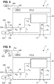
- the trailer control module 1 is shown in detail according to a first embodiment.
- the electro-pneumatic trailer control module 1 has a housing 2 in which an electronic control unit ECU and a trailer control valve unit 65 are arranged.
- the trailer control valve unit 65 has a plurality of valves, which are described in detail below.
- a supply inlet 11 is formed on the housing 2 and is connected to the third compressed air supply 525 via a supply pressure supply line 526.
- a redundancy pressure connection 42 to which a redundancy pressure supply line 552 is connected
- a parking brake pressure input 43 to which a parking brake pressure line 550 is connected, which in this exemplary embodiment is in turn connected to the electropneumatic handbrake unit (EPH) 541 (cf. Fig.
- the trailer control module 1 also has two pneumatic outputs, namely on the one hand a trailer supply pressure connection 21, to which the supply pressure P V is applied, and a trailer brake pressure connection 22, at which a brake pressure P B can be controlled.
- a supply pressure distribution line 50 runs from the supply inlet 11, via which various components of the trailer control module 1 are supplied with supply pressure P V.
- the trailer control valve unit 65 has an inlet-outlet valve unit 66, also referred to as a pilot control unit, which has an inlet valve IV, an outlet valve OV and a switching valve, designed here as a redundancy valve RV. Furthermore, the trailer control valve unit 65 has a first relay valve 20 which is not designed as an inverse relay valve, but rather as a "normal relay valve”.
- the inlet valve IV is designed as a 2/2-way valve and has a first inlet valve connection 67a and a second inlet valve connection 67b.
- the first inlet valve connection 67a is connected to a first supply pressure branch line 68 branching off from the supply distribution line, and the second inlet valve connection 67b is connected to a first control line 69.
- a service brake control pressure (first control pressure) P 1 can be controlled in the first control line 69 by electrically switching the inlet valve IV based on a signal S 1 from the control unit ECU.
- the first control line 69 is connected to a relay valve control input 25 of the relay valve 20.
- the relay valve 20 also has a relay valve working input 23, a relay valve output 24 and a relay valve venting output 26.
- the relay valve vent outlet 26 is connected to a pressure sink 3.
- the relay valve working input 23 serves to receive a supply pressure P V and is initially connected to a second supply pressure branch line 71, which is connected to a first connection 72a of a trailer demolition valve 73.
- the trailer demolition valve 73 is designed as a pneumatically switched 2/2-way valve and open without pressure, in which in Fig. 2 switching position shown.
- the first connection 72a of the trailer demolition valve 73 is connected via a throttle to the second connection 72b of the trailer demolition valve 73, which in turn is connected to the supply pressure distribution line 50 via a third supply pressure branch line 74.
- the trailer demolition valve 73 is in the in Fig. 2 position shown, so that the supply pressure P V is applied to the relay valve working input 23.
- the trailer supply connection 21 is also supplied with supply pressure P V by means of a trailer supply line 86.
- the relay valve 20 If the relay valve 20 now receives the service brake control pressure P 1 at the relay valve control input 25, the relay valve 20 controls a corresponding relay working pressure P 2 at the relay valve output 24 and provides this via a trailer brake pressure line 75 to the trailer brake pressure connection 22 as brake pressure P B .
- a brake pressure sensor 76 is provided for the trailer control module 1, which is connected to the trailer brake pressure line 75 via a brake pressure measurement line 77 and provides a corresponding pressure signal S DA to the control unit ECU.
- the outlet valve OV is switched electro-pneumatically and upon receipt of a signal S 2 from the control unit ECU from the first in Fig. 2 de-energized switching state shown, in which it is closed, to an open switching state, which is shown in Fig. 2 is not shown, relocatable.
- the outlet valve OV is provided for venting the service brakes 510a, 510b of the trailer truck 504 and thus for reducing a brake pressure P B at the trailer brake pressure connection 22.
- the outlet valve OV like the inlet valve IV, is designed as a 2/2-way valve and has a first outlet valve port 78a and a second outlet valve port 78b.
- the first outlet valve connection 78a is connected to the first control line 69 and the second outlet valve connection 78b to a pressure sink 3.
- inlet and outlet valves IV / OV are integrated and designed as a 3/2-way valve, a first connection being connected to the first supply pressure branch line 68, a second connection to the first control line 69 and a third connection to the pressure sink 3.
- the trailer control module 1 has the redundancy pressure connection 42.
- a brake signal transmitter is connected to the redundancy pressure connection 42 via a redundancy pressure supply line 552 528 connected (cf. Fig. 1 ).
- a first redundancy pressure line 16 is connected to the redundancy pressure connection 42 inside the housing 2.
- the redundancy pressure line 16 runs to a pneumatic switching valve 13, more precisely it is with a first connection 14a of the switching valve 13 (which will be described in more detail below).
- the switching valve 13 is in the second switching position, not shown, and the first connection 14a is in connection with the third connection 14c.
- a second redundancy pressure line 17 is then connected to a third connection 14c of the switching valve 13, which in turn is connected to a first redundancy valve connection 80a of a redundancy valve RV.
- the second redundancy valve connection 80b is connected to a redundancy pressure control line 81 which opens into the first control line 69 and thus into the relay valve control input 25 of the relay valve 20.
- the redundancy valve RV is designed as a 2/2-way valve and has a first and a second switching position, it being shown in FIG Fig. 2 is shown in the first open switch position.
- the redundancy valve RV is open when de-energized and also serves to be able to control a brake pressure P B in the event of a fault in which the inlet-outlet valve unit 66 is de-energized.
- a redundancy pressure P R is controlled in the redundancy pressure supply line 552 by pressing the pedal 590 of the brake value transmitter 528, this redundancy pressure P R is applied via the first redundancy pressure line 16, the switching valve 13, the second redundancy pressure line 17, the open redundancy valve RV and the redundancy pressure control line 81 the relay valve control input 25 of the relay valve 20 is provided.
- the brake pressure P B is then controlled at the relay valve output 24 of the relay valve 20.
- a parking brake valve unit 12 provided with the pneumatically controlled switching valve 13, which is designed as a 3/2-way valve 14 and which has a pneumatic control input 15 for receiving a pneumatic control pressure P 3 , the pneumatically controlled switching valve 13 when the parking brake pressure input 43 is connected to the pressure sink 3, that is, when the parking brake 6 is vented, it is switched in such a way that a brake pressure P B at the trailer brake pressure connection 22 can be controlled.
- the third connection 14c is connected to the second connection 14b, to which a fourth supply pressure branch line 41 is connected, which in turn branches off from the supply pressure distribution line 50 and to which the supply pressure P V is applied.
- the particular advantage here is that an inverse relay piston does not have to be used, but rather the pneumatically controlled switching valve 13 is switched based on the control pressure P 3 , which in particular is independent of a flowing current.
- the parking brake pressure P P at the parking brake pressure input 43 is preferably used as the control pressure P 3 .
- This is in the specific embodiment shown in Fig. 2 is shown, released by a pneumatic control line 83 which connects the parking brake pressure input 43 to the control input 15 of the pneumatically controlled switching valve 13. That is to say, in this embodiment with an electropneumatic handbrake, the pressure of the spring accumulator 6 is applied to the control input 15 of the pneumatically controlled switching valve 13.
- the control pressure of the trailer connection of the parking brake valve in the driver's cab is preferably connected to the parking brake pressure input 43. This is then used to control the supply pressure in the first switch position (driving position), control the ambient pressure in the second switch position (parking position) and control the supply pressure in the third switch position (trailer control position).
- the pneumatically controlled switching valve 13 is in the second switching position, not shown, and the brake pressure is controlled P B at the trailer brake pressure connection 22 is prevented in this switching position.
- the spring accumulators 6 are pressurized, and thus the pneumatically controlled 3/2-way valve 14 is in the second (not shown) switching position, and the redundancy pressure P R is controlled at the third connection 14c (if one is specified).
- the redundancy valve RV is already de-energized in this status and is thus opened, and as a result the fourth control pressure P 4 is applied to the relay valve control input 25 of the relay valve 20. In this way, a corresponding brake pressure P B is controlled at the trailer brake pressure connection 22.
- the redundancy valve RV when parking begins or the parking brake is applied in stages, the redundancy valve RV is initially energized with the signal S 3 and closed; the control pressure P 4 output by the switching valve 13 is initially locked out.
- the application of the service brakes 510a, 510b of the trailer 504 is implemented at the beginning of the parking via the inlet / outlet valve unit 66, which is switched accordingly by the control unit ECU. That is, if, for example, the handbrake switch 534 is actuated, the redundancy valve RV initially remains closed.
- the control unit ECU switches the inlet valve IV so that the service brake control pressure P 1 is applied to the relay valve control input 25 and a corresponding brake pressure P B is controlled at the trailer brake pressure connection 22, while the spring accumulator 6 is gradually venting and develop their braking power.
- all valves RV, IV, OV of the inlet-outlet valve unit 66 are de-energized; the inlet valve IV closes while the redundancy valve RV is opened.
- the fourth control pressure P 4 is now applied to the relay valve control input 25 via the switching valve 13 and the redundancy valve RV and the braking pressure P B is controlled; the service brakes 510a, 510b of the trailer 504 remain engaged.
- the trailer control module 1 also has a first CAN bus connection 30 to which the first CAN bus line 554 is connected.
- This first CAN bus connection 30 is designed as an input 31 for a trailer control position signal S K. Since in this embodiment ( Fig. 1 , 2 ) an electropneumatic handbrake (EPH) is provided, the trailer control position signal S K is transmitted electronically.
- EPH electropneumatic handbrake
- the trailer control position signal S K is transmitted electronically.
- European trailer control for which the trailer control module 1 according to the first exemplary embodiment ( Fig. 2 ) is provided, it is necessary that the vehicle driver can engage a trailer control position.
- the trailer control position is used to check whether the vehicle train 500 is standing safely solely on the basis of the parking brakes 6, 532a, 532b of the towing vehicle 502.
- the control unit ECU is set up to process the trailer control position signal S K and to send a corresponding switching signal S 3 to the redundancy valve RV, so that the redundancy valve RV is in the second, in Fig. 2 switch position not shown switches so that the control pressure P 4 is locked out.
- the outlet valve OV must be opened briefly in order to vent any pressure that is currently locked in. In this case, there is no service brake control pressure P 1 at the relay valve control input 25, and no brake pressure P B is output at the trailer brake pressure connection 22.
- the parking brake valve (not shown) of the driver's cab via which the vehicle driver requests the parking position and also the trailer control position, is preferably connected to the parking brake pressure input 43 . If the vehicle driver selects the trailer control position by means of the parking brake valve, a control pressure is output at the parking brake pressure input 43, so that the switching valve 13 in the in Figure 2 The second switching position, not shown, remains and accordingly no control pressure P 4 is controlled. Consequently, no parking brake pressure P B is output at the trailer brake pressure connection 22 either. Thus the position of the trailer can be checked.
- the control unit ECU in this embodiment also has a parking brake signal input 200 for receiving a first electronic brake representation signal S B1 , which represents the actuation of a parking brake 6, 532a, 532b of the towing vehicle 502.
- the parking brake signal input 200 is in this embodiment ( Fig. 2 ) connected to a second CAN bus connection 202 to which a second CAN bus line 204 is connected, which in turn is connected to the central module 527.
- the first brake representation signal S B1 is in this case an electronic signal that is provided by the central module 527.
- the first brake representation signal S B1 represents braking by means of the parking brakes 6, 532a, 532b and, in a simple embodiment, can be the signal that the central module 527 sends to the handbrake unit 541.
- the first brake representation signal S B1 is one of them derived signal or an independent signal that is provided by the central module 527.
- the control unit ECU is set up to switch at least one valve, preferably the inlet valve IV, based on the received first brake representation signal S B1 by means of a signal S 1 , so that a brake pressure P B is controlled at the trailer brake pressure connection 22.
- a brake pressure P B is controlled at the trailer brake pressure connection 22.
- the relay valve 20 then controls a relay working pressure P 2 at the relay valve output 24, so that the brake pressure P B is applied to the trailer brake pressure connection 22.
- a particularly simple integration of the trailer control module 1 into an existing towing vehicle 502 is achieved. It is not necessary to provide an additional valve or the like in order to achieve a connection between the electropneumatic handbrake unit (EPH) 541 and the trailer control module 1. Rather, it is sufficient to provide a corresponding second CAN bus line 204 from the central module 527 to the second CAN bus connection 202, so that the first brake representation signal S B1 can be provided at the parking brake signal input 200.
- EPH electropneumatic handbrake unit
- the electro-pneumatic trailer control module 1 according to this embodiment ( Fig. 2 ), more precisely the electronic control unit ECU, also has a further connection 250 for receiving a redundant electronic brake representation signal S B4 .
- a redundant electronic brake representation signal S B4 can, for example, in addition to the usual received deceleration request signal for the service brakes 510a, 510b of the trailer 504 may be a redundant electronic signal controlled by a manual brake value transmitter 528.
- the braking value transmitter 528 has a position transmitter which converts an actuation of the pedal 590 into an electronic signal.
- connection 250 is connected to a signal line 252.
- Electropneumatic trailer control module 1 optionally has a CAN bus connection 202a (cf. Fig. 1 ), to which a CAN bus 555 is connected, which leads to the parking brake unit 541.
- the trailer control module 1 can also receive the redundant electronic brake representation signal S B4 via this CAN bus 555 in the event of a fault.
- the trailer control module 1 has an additional (in the Figure 2 not shown; see. Figure 7 and 10 ) Pressure sensor which redundantly detects the redundant pressure P R and provides a corresponding pressure signal S DR as the redundant brake representation signal S B4 at the connection 250.
- FIG. 3 to 9 now show further exemplary embodiments of the electro-pneumatic trailer control module, the trailer control valve unit 65 only being shown schematically as a "black box".
- the trailer control valve unit can in the embodiments of Figures 3 to 9 be designed as in the embodiment of Fig. 2 .
- the corresponding line connections are designated below. Identical and similar elements are provided with the same reference symbols, so that reference is made in full to the above description.
- a first difference in the embodiment according to FIG Fig. 3 to the embodiment according to Fig. 2 lies in the design of the pneumatically controlled switching valve 13.
- the third connection 14c of the switching valve 13 is connected to a first shuttle valve inlet 18a of a shuttle valve 18.
- the shuttle valve 18 is preferably designed as a double-acting check valve 19, that is to say as a so-called select high valve.
- the shuttle valve 18 has a second shuttle valve inlet 18b.
- the respective higher pressure at the shuttle valve inlets 18a, 18b is at the shuttle valve outlet 18c controlled.
- the first redundancy pressure line 16 is in this embodiment ( Fig. 3 ) not connected directly to the first connection 14a of the switching valve 13, but to the second shuttle valve inlet 18b.
- the in Fig. 3 In the in Fig.
- the depressurized switching position of the switching valve 13 shown is thus applied to the first changeover valve inlet 18a, the supply pressure P V , while the redundancy pressure P R is applied to the second changeover valve inlet 18b.
- a control pressure P 4 is output into the second redundancy pressure line 17, which is connected to the shuttle valve outlet 18c.
- the control pressure P 4 is the respective higher pressure of the supply pressure P V and the redundancy pressure P R.
- the parking brakes of the tractor 502 are released, so that a control pressure P 3 is applied to the control input 15 of the switching valve 13.
- the switching valve 13 is then in the in Fig. 3 second switching position, not shown, in which the first connection 14a is connected to the third connection 14c.
- the first connection 14a is in this exemplary embodiment ( Fig. 3 ) connected to a pressure sink 3. That is, during normal driving operation, ambient pressure P 0 is present at port 14c, so that only redundancy pressure P R can be output into second redundancy pressure line 17 as control pressure P 4 via shuttle valve 18. If the parking brakes of the towing vehicle are now applied, that is to say the spring accumulator 6 is vented, the switching valve 13 switches to the in Fig. 3 position shown. A control pressure P 4 is consequently output in the second redundancy pressure line 17, which leads to a braking pressure P B being output at the trailer brake pressure connection 22. The service brakes of trailer vehicle 504 are applied.
- the parking brake signal input 200 is designed to be connected to a pressure sensor 208.
- the pressure sensor 208 is designed as an external pressure sensor 209.
- the external pressure sensor 209 is connected to a pressure sensor connection 206 on the housing 2 of the trailer control module 1 by means of a signal line 210.
- the parking brake signal input 200 is in connection with the pressure sensor connection 206, so that the parking brake signal input 200 receives a signal from the external Pressure sensor 209 can receive.
- the external pressure sensor 209 preferably detects the pressure on a parking brake, in particular the pressure on a cylinder 6a of a spring accumulator 6, in order to provide a corresponding pressure signal S D as a second brake representation signal S B2 at the pressure sensor connection 206 and thus at the parking brake signal input 200.
- the external pressure sensor 209 can ultimately be installed somewhere in the train carriage 502. This makes it possible to achieve a particularly simple integration of the trailer control module 1 into an existing towing vehicle 502, especially with a conventional pneumatic parking brake. It is only necessary to lay a signal line from an existing external pressure sensor 209 to the pressure sensor connection 206 so that the brake representation signal S B2 can be provided in the form of the pressure signal S D at the parking brake signal input 200.
- the further functioning of the trailer control module 1 according to the second exemplary embodiment ( Fig. 3 ) is identical to that of the first exemplary embodiment ( Fig. 2 ).
- the third embodiment ( Fig. 4 ) is a combination of the first and second exemplary embodiment. While the parking brake valve unit 12 in the third embodiment ( Fig. 4 ) according to the second embodiment ( Fig. 2 ), the parking brake signal input 200 is according to the first embodiment ( Fig. 2 ) connected to the second CAN bus connection 202, to which the second CAN bus line 204 is connected, which in turn runs to the central module 527. In this respect, the above description of the Fig. 2 and 3 referenced.
- the parking brake signal input 200 is in turn designed to be connected to a pressure sensor 208.
- the pressure sensor 208 is designed as an internal pressure sensor 212.
- the parking brake signal input 200 is connected to the internal pressure sensor 212 via an internal interface 214.
- the internal pressure sensor 212 is connected via a measuring line 216 to the pneumatic control line 83, in which the control pressure P 3 is controlled via the parking brake pressure input 43.
- the internal pressure sensor 212 detects the parking brake pressure output at the parking brake pressure input 43, which corresponds to the brake pressure in the parking brakes, in particular spring accumulators 6, or an equivalent pressure of a pilot control unit for the parking brakes or the pressure that is output by a parking brake valve on the trailer connection.
- the internal pressure sensor 212 provides a pressure signal S DI at the internal interface 214, which is provided at the parking brake signal input 200 as a third brake representation signal S B3 .
- the pressure signal S DI thus forms the brake representation signal S B3 according to the fourth and fifth exemplary embodiments.
- the trailer control module 1 according to the fourth and fifth exemplary embodiments is identical to the first three exemplary embodiments. Again, it is a trailer control module 1 for a “European trailer control”, and to this extent the trailer control module has the parking brake valve unit 12.
- the parking brake valve unit 12 according to the fourth embodiment ( Fig. 5 ) corresponding to the second and third exemplary embodiment ( Fig. 3 and 4th ) is formed, the parking brake valve unit 12 in the fifth embodiment ( Fig. 6 ) according to the first embodiment ( Fig. 2 ) educated. That is, in the fourth embodiment ( Fig. 5 ) the control pressure P 4 is controlled via the shuttle valve 18, while in the fifth embodiment ( Fig. 6 ) a direct modulation of the control pressure P 4 via the 3/2-way valve 14 takes place.
- Fig. 7 now illustrates a sixth embodiment, which is basically based on the fifth embodiment ( Fig. 6 ) builds up. Identical and similar elements are provided with the same reference numerals and in this respect reference is made in full to the above description.
- the redundant pressure sensor 90 is connected to the first redundancy pressure line 16 via a redundancy pressure measuring line 91. As a result, the redundant pressure sensor 90 measures the redundant pressure P R in the first redundancy pressure line 16, which is controlled manually by actuating the brake pedal 590 at the redundancy pressure connection 42.
- the manually controlled redundancy pressure P R via the first redundancy pressure line 16 possibly the shuttle valve 18, the second redundancy pressure line 17, the redundancy valve RV, the redundancy pressure control line 81 and the relay valve 20 (cf. Fig. 2 ) leads to a brake pressure P B controlled at the trailer brake pressure connection 22.
- the redundant pressure sensor 90 can be used to detect a driver interaction with autonomous control of the brake system 520.
- the redundant pressure sensor 90 measures the manually controlled redundancy pressure P R and provides a corresponding redundancy pressure signal S DR to the control unit ECU.
- the redundancy pressure signal S DR provided by the redundant pressure sensor 90 represents a driver's request, since the redundant pressure sensor 90 detects the redundancy pressure P R controlled manually by means of the braking value transmitter 528.
- the control unit ECU is preferably set up to compare the redundancy pressure signal S DR , which it receives from the pressure sensor 90, with an autonomously controlled operating brake signal, which it receives, for example, from the control unit 536 for autonomous driving.
- the control unit ECU causes the redundancy valve RV to be switched in order, based on the redundancy pressure P R, to manually control a brake pressure P B at the trailer brake pressure connection 22 to enable.
- the control unit 536 is locked out and the driver takes over manually.
- the embodiments seven, eight, nine and ten now each show a trailer control module 1 for the "Scandinavian trailer control".
- the embodiments seven, eight, nine and ten differ therefore differ from the previous exemplary embodiments essentially in that they do not have a parking brake valve unit 12, since in the "Scandinavian trailer control" the control of a brake pressure P B at the trailer brake pressure connection 22 in the event that the parking brakes of the towing vehicle 502 are engaged should only take place temporarily , and the service brakes of the trailer are then released again in the parking position.
- the parking brake signal input 200 of the trailer control module 1 is set up to receive the brake representation signal S B1 from the central module 527.
- the electro-pneumatic trailer control module 1 can also send the brake representation signal S B1 via the third CAN bus 555 and the CAN bus termination 202a (cf. Fig. 1 ) received directly from the electronic control unit of the parking brake unit 541.
- the parking brake signal input 200 is designed to receive a pressure signal S D as a brake representation signal S B2 from a pressure sensor 208, in this case an external pressure sensor 209.
- a pressure sensor 208 in this case an external pressure sensor 209.
- the ninth embodiment ( Fig. 10 ) is again based on the seventh embodiment ( Fig. 8 ), but includes, like the sixth embodiment ( Fig. 7 ) a redundant pressure sensor 90.
- a redundant pressure sensor 90 For a detailed description of the redundant pressure sensor 90, reference is made to the above description of the sixth embodiment ( Fig. 7 ) referenced.
- the parking brake signal input 200 is designed to receive the brake representation signal SB3 as a pressure signal S DI from a pressure sensor 208, in this case an internal pressure sensor 212, to receive.
- a pressure sensor 208 in this case an internal pressure sensor 212
- the parking brake signal input 200 is designed accordingly.
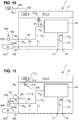
- FIGS Figures 12 and 13 now illustrate further variants of the trailer control valve unit 65, and it can be seen that the trailer control valve unit 65 according to FIGS Figures 12 and 13 those from the Figures 2 to 11 can replace each.
- the redundancy valve RV is designed as a 3/2-way valve 120.
- the main difference lies in the interconnection of the redundancy valve RV, which is designed as a 3/2-way valve 120.
- Another difference lies in the reversal of the outlet valve OV, which is reversed in the switching positions so that it is open when de-energized, as in FIG Fig. 10 switching position shown.
- the outlet valve is ( Fig. 2 ) with its second outlet valve port 78b is not connected directly to the pressure sink 3, but to a first connecting line 122 which connects the second outlet valve port 78b to the second redundancy valve port 80b.
- the third redundancy valve connection 80c of the 3/2-way valve 120 is connected to the pressure sink 3 via a further vent branch line 124.
- the mode of operation of this layout is as follows: In normal driving operation, the outlet valve OV is switched into the second, closed switching position, not shown, based on a signal S 2 provided by the control unit ECU. A service brake control pressure P 1 at the relay valve control input 25 of the relay valve 20 can then be controlled by switching the inlet valve IV based on the signal S 1 of the electronic control unit ECU, and based on this, in turn, a relay working pressure P 2 at the relay valve output 24 The redundancy valve RV is also in the Normal driving mode in the second shift position, not shown, based on a signal S 3 . In the currentless state (as in Fig.
- the first redundancy valve port 80a is connected to the second redundancy valve port 80b, so that the redundancy pressure P R can be controlled in the first connecting line 122.
- the redundancy pressure P R is locked out, and so the signal S 3 is applied in order to bring the redundancy valve RV into the second switching position, not shown.
- the second redundancy valve connection 80b is connected to the third redundancy valve connection 80c. That is, in the second switching position, not shown, of the redundancy valve RV, the pressure sink 3 is connected to the second outlet valve port 78b. Consequently, the relay valve control input 25 can be vented into the de-energized position via a corresponding switching of the outlet valve OV, so as not to control any brake pressure P B at the trailer brake pressure connection 22.
- a second variant is in Fig. 13 shown. Even with the in Fig. 13 The variant of the trailer control valve unit 65 shown here, the redundancy valve RV is designed as a 3/2-way valve 120.
- the first redundancy valve connection 80a is in turn connected to the redundancy pressure connection 42 via the first redundancy pressure line 16.
- the second redundancy valve connection 80b is, as is also the case in the first exemplary embodiment ( Fig. 2 ) is the case with a pneumatic line, here a second connecting line 126 connected.
- the third redundancy valve connection 80c is connected to the first supply pressure branch line 68.
- the second connecting line 126 is also connected to the first inlet valve port 67a and the second inlet valve port 67b is connected to the first control line 69, as is also the case in the first exemplary embodiment.
- the mode of operation of this circuit layout is as follows: In the de-energized state, that is to say without signal S 3 , the redundancy valve RV is in the in Fig. 13 first switch position shown. In the first currentless switching position, the first redundancy valve connection 80a is connected to the second redundancy valve connection 80b. In the de-energized position, a redundancy pressure P R can therefore be controlled on the second connecting line 126. During normal driving operation, however, a signal S 3 is switched so that the third redundancy valve connection 80c is connected to the second redundancy valve connection 80b and the supply pressure P V is controlled on the second connecting line 126.
- Inlet valve IV is normally open and in the first switching position (in Fig. 13 shown), the outlet valve OV is normally closed and in the first switching position (in Fig. 13 shown). During normal driving, the inlet valve IV is closed and a signal S 1 is present. If the inlet valve IV is now opened, the service brake control pressure P 1 can flow from the supply inlet 11 via the first supply branch line 68, the third redundancy valve connection 80c, the second redundancy valve connection 80b, the second connecting line 126, the first inlet valve connection 67a, the second inlet valve connection 67b and the first control line 69 can be controlled at the relay valve control input 25, which in turn controls a brake pressure P B at the trailer brake pressure connection 22.
- the electronic control unit ECU then sends a signal S 2 to the outlet valve OV, so that it is switched to the second switching position (open switching position) while the inlet valve is in operation IV is placed in the closed second switching position with a signal S 1 .
- the relay valve control input 25 is therefore connected to the pressure sink 3 via the first control line 69, the first outlet valve connection 78a, the second outlet valve connection 78b and the vent branch line 79 and can be vented.
- the brake pressure P B decreases again.
- the position of the valves RV, IV, OV is selected such that, in the event that the control unit ECU fails, a redundancy pressure P R at the redundancy pressure connection 42 results in a brake pressure P B being output at the trailer brake pressure connection 22 .
- the redundancy valve RV connects the redundancy pressure connection 42 to the second connecting line 126.
- the inlet valve IV is open when de-energized and the redundancy pressure P R can reach the first control line 69 via the inlet valve IV.
- the outlet valve OV is closed and blocks the first control line 69 from the pressure sink 3.
- the redundancy pressure PR is applied to the relay valve control input 25 and a brake pressure P B can be controlled at the trailer brake pressure connection 22.
- the relay valve 20 is different from the prior art, with a common control chamber 100, in this embodiment only a single control chamber 100, (cf. Fig. 14 ) educated.
- the relay valve 20 has a relay valve control input 25, the relay valve working input 23, to which the second supply pressure branch line 71 of the supply pressure distribution line 50 is connected and to which the pressure P V is applied, a relay valve output 24 which is supplied via the trailer brake pressure line 75 is connected to the trailer brake pressure connection 22 and via which the relay working pressure P 2 or the brake pressure P B can be controlled, as well as a relay valve venting output 26, through which the relay valve output 24 can be vented and which is connected to the pressure sink 3 .
- a pressure P 0 is consequently present at the relay valve vent outlet 26, which corresponds to the pressure of the pressure sink 3, in particular the environment.
- the relay valve 20 has a common control chamber 100 into which the single relay valve control inlet 25 opens. It can be provided that further control inputs open into the control chamber 100. Both the service brake control pressure P 1 and the redundancy pressure P R can be controlled into the common control chamber 100 via the relay valve control input 25; in this respect, only one common control chamber 100 is provided for the two control pressures P 1 , P R.
- the control chamber 100 thus fulfills two functions: on the one hand, the brake pressure P B can be controlled as a function of the service brake control pressure P 1 by means of the control chamber 100, and on the other hand, the brake pressure P B can also be controlled as a function of the redundancy pressure P R by means of the control chamber 100.
- the control chamber 100 acts on a single control piston 102.
- the single control piston 102 is guided along an axis A in an axially sliding manner.
- the control piston 102 can move with respect to Fig. 14 move downward and comes with a valve seat 104 in contact with a corresponding slide ring 106, which is spring-loaded into the axially upper position.
- a spiral spring 108 is provided for this purpose.
- the sliding ring 106 has a second valve seat 110, which seals against a projection 112 and thus initially keeps the relay valve operating inlet 23 closed.
- the control piston is in Fig. 14 shown in an open position. In its closing position, the valve seat 104 is in contact with the sliding ring 106. In the closing position, both the relay valve work inlet 23 and the relay valve outlet 24 are closed off from the relay valve vent outlet 26.
- a force acts on the control piston 102, which leads to the opening of the second valve seat 110 so that the pressure P V can jump into the working chamber 114.
- the pressure in the working chamber 114 rises and leads to a counterforce on the control piston 102, so that the control piston moves back into the closing position.
- a brake pressure P B is controlled at the relay valve output 24 and held there.
- Figure 15 now shows an eleventh embodiment. Basically it's similar in Figure 15 Brake system 520 shown corresponding to that Figure 1 and the same and similar elements are provided with the same reference symbols. In this respect, the above description of the Fig.1 Referenced. The following therefore essentially deals with the differences. The difference lies in the interconnection in the layout of the brake system 520; This change has little or no influence on the electro-pneumatic trailer control module 1.
- the redundancy connection 42 is not connected via the redundancy pressure supply line 552 to the bypass 553 and via this to the braking value transmitter 528; rather, the brake pressure of another vehicle axle, in this exemplary embodiment the front axle brake pressure P BV , is controlled at the redundancy connection 42.
- a third redundancy pressure supply line 694 is provided, which is connected to a front axle brake pressure line 693 via a T-piece 692.
- the front axle brake pressure P BV of the service brakes 530a, 530b of the front axle at the redundancy pressure connection 42 is controlled via this third redundancy pressure supply line 694.
- the braking value transmitter 528 is then different from the first embodiment ( Fig. 1 ) connected only to the bypass 533 and connected via this to the front axle modulator 529 in order to control the brake signal transmitter control pressure P BST redundantly at the front axle modulator 529.
- the brake signal transmitter control pressure P BST which is controlled manually by means of the foot pedal 590 Front axle modulator 529 to be controlled as redundancy pressure P R at redundancy pressure connection 42 of electropneumatic control module 1.
Landscapes
- Engineering & Computer Science (AREA)
- Transportation (AREA)
- Mechanical Engineering (AREA)
- Physics & Mathematics (AREA)
- Electromagnetism (AREA)
- Fluid Mechanics (AREA)
- Braking Systems And Boosters (AREA)
- Regulating Braking Force (AREA)
- Valves And Accessory Devices For Braking Systems (AREA)
Applications Claiming Priority (3)
| Application Number | Priority Date | Filing Date | Title |
|---|---|---|---|
| DE102017002953 | 2017-03-21 | ||
| DE102017005980.2A DE102017005980A1 (de) | 2017-03-21 | 2017-06-24 | Integriertes Anhängersteuermodul (TCV) mit externer elektropneumatischer Handbremseinheit (EPH) |
| PCT/EP2018/056995 WO2018172340A1 (de) | 2017-03-21 | 2018-03-20 | Integriertes anhängersteuermodul (tcv) mit externer elektropneumatischer handbremseinheit (eph) |
Publications (2)
| Publication Number | Publication Date |
|---|---|
| EP3600996A1 EP3600996A1 (de) | 2020-02-05 |
| EP3600996B1 true EP3600996B1 (de) | 2021-01-27 |
Family
ID=63449787
Family Applications (1)
| Application Number | Title | Priority Date | Filing Date |
|---|---|---|---|
| EP18715524.7A Active EP3600996B1 (de) | 2017-03-21 | 2018-03-20 | Integriertes anhängersteuermodul (tcv) mit externer elektropneumatischer handbremseinheit (eph) |
Country Status (5)
| Country | Link |
|---|---|
| US (1) | US11807208B2 (zh) |
| EP (1) | EP3600996B1 (zh) |
| CN (1) | CN110461672B (zh) |
| DE (1) | DE102017005980A1 (zh) |
| WO (1) | WO2018172340A1 (zh) |
Families Citing this family (10)
| Publication number | Priority date | Publication date | Assignee | Title |
|---|---|---|---|---|
| DE102017121761B4 (de) * | 2017-09-20 | 2021-02-18 | Knorr-Bremse Systeme für Nutzfahrzeuge GmbH | Elektropneumatisches Bremssystem mit Testmodus für den pneumatischen Backup-Bremskreis sowie Fahrzeug mit einem solchen Bremssystem |
| FR3083764B1 (fr) * | 2018-07-10 | 2020-09-25 | Poclain Hydraulics Ind | Procede et circuit de freinage hydraulique d'urgence ameliores pour attelage |
| DE102019100869A1 (de) * | 2019-01-15 | 2020-07-16 | Wabco Gmbh | Ventilanordnung eines hydraulisch gebremsten Zugfahrzeugs zur Steuerung des Bremsdruckes eines pneumatisch gebremsten Anhängerfahrzeugs |
| DE102019114270A1 (de) * | 2019-05-28 | 2020-12-03 | Wabco Gmbh | Elektronisch gesteuertes pneumatisches Bremssystem mit zwei Einkanal- Achsmodulatoren und ABS-Ventilen sowie Fahrzeug mit einem solchen Bremssystem |
| US11021142B2 (en) * | 2019-07-08 | 2021-06-01 | Bendix Commercial Vehicle Systems Llc | Trailer control valve with integrated trailer supply |
| US11724676B2 (en) | 2019-11-05 | 2023-08-15 | Bendix Commercial Vehicle Systems Llc | Trailer detection and control module |
| CN111055828B (zh) * | 2019-12-31 | 2021-02-02 | 威伯科汽车控制系统(中国)有限公司 | 一种支持商用车完全自动驾驶的冗余制动系统 |
| CN111959464A (zh) * | 2020-08-03 | 2020-11-20 | 浙江吉利新能源商用车集团有限公司 | 一种用于半挂汽车列车的制动控制方法、系统及车辆 |
| CN116601060A (zh) * | 2020-10-21 | 2023-08-15 | 采埃孚商用车系统欧洲有限公司 | 挂车制动控制模块 |
| EP4116161B1 (en) * | 2021-07-06 | 2024-03-06 | Volvo Truck Corporation | Heavy duty vehicle redundant braking system |
Family Cites Families (59)
| Publication number | Priority date | Publication date | Assignee | Title |
|---|---|---|---|---|
| US4372620A (en) * | 1981-02-04 | 1983-02-08 | The Budd Company | Anti-locking brake system for a vehicle |
| DE3514949A1 (de) * | 1985-04-25 | 1986-10-30 | Wabco Westinghouse Fahrzeugbremsen GmbH, 3000 Hannover | Druckmittel-bremsanlage fuer den anhaenger eines fahrzeuges |
| EP0387004A3 (en) * | 1989-03-08 | 1990-11-22 | LUCAS INDUSTRIES public limited company | Trailer braking system for a towing vehicle |
| US5061015A (en) * | 1990-04-12 | 1991-10-29 | Allied-Signal Inc. | Tractor protection control system |
| US5090780A (en) * | 1991-05-03 | 1992-02-25 | Westinghouse Air Brake Company | Binary weighted digital flow regulating system |
| GB9215510D0 (en) * | 1992-07-22 | 1992-09-02 | Grau Ltd | Braking systems |
| US5585554A (en) * | 1994-10-31 | 1996-12-17 | Handfield; Michael | System and method for monitoring a pneumatic tire |
| US20030111902A1 (en) * | 2001-12-17 | 2003-06-19 | David Thiede | Intelligent braking system and method |
| US7784879B2 (en) * | 2002-07-16 | 2010-08-31 | Haldex Brake Corporation | Electronic control air management with parking brake and trailer supply control |
| DE10320608B4 (de) | 2003-05-08 | 2005-08-11 | Knorr-Bremse Systeme für Nutzfahrzeuge GmbH | Bremsanlage für Fahrzeuge, insbesondere Nutzfahrzeuge mit mindestens zwei separaten elektronischen Bremssteuerkreisen |
| DE10336611A1 (de) * | 2003-08-08 | 2005-03-03 | Wabco Gmbh & Co.Ohg | Druckmittelbetriebene Bremsanlage für ein Fahrzeug |
| DE102004051309B4 (de) | 2004-10-21 | 2006-08-17 | Knorr-Bremse Systeme für Nutzfahrzeuge GmbH | Aus Moduln mit elektrischen und/oder pneumatischen Komponenten aufgebaute elektro-pneumatische Zentraleinheit eines Nutzfahzeugs |
| DE102005058799A1 (de) * | 2005-12-09 | 2007-06-14 | Wabco Gmbh | Elektropneumatische Bremssteuerungseinrichtung |
| DE102005060225A1 (de) * | 2005-12-16 | 2007-06-21 | Wabco Gmbh | Elektropneumatische Bremssteuerungseinrichtung |
| US7690735B2 (en) * | 2006-05-12 | 2010-04-06 | Bendix Commercial Vehicle Systems Llc | Service work brake arrangement |
| DE102006036748A1 (de) * | 2006-08-05 | 2008-02-07 | Wabco Gmbh | Elektrisch gesteuerte Bremsanlage |
| DE102006041009A1 (de) * | 2006-08-31 | 2008-03-06 | Wabco Gmbh | Bremsanlage für ein Fahrzeug |
| DE102006041011A1 (de) * | 2006-08-31 | 2008-03-06 | Wabco Gmbh | Ventileinheit für eine elektropneumatische Bremssteuerungseinrichtung |
| DE102006041010A1 (de) * | 2006-08-31 | 2008-03-06 | Wabco Gmbh | Ventileinheit sowie elektropneumatische Bremssteuerungseinrichtung für eine Fahrzeugfeststellbremse |
| DE102006041012A1 (de) * | 2006-08-31 | 2008-03-06 | Wabco Gmbh | Ventileinheit, Bremssteuerungseinrichtung, Fahrzeugbremsanlage sowie Fahrzeug |
| DE102007014423A1 (de) | 2007-03-22 | 2008-09-25 | Knorr-Bremse Systeme für Nutzfahrzeuge GmbH | Feststellbremsanlage für Nutzfahrzeuge und Betriebsverfahren für eine Feststellbremsanlage |
| GB2450468B (en) * | 2007-03-22 | 2011-06-01 | Knorr Bremse Systeme F R Nutzfahrzeuge Gmbh | Trailer electronic braking system |
| DE102007037346C5 (de) * | 2007-08-08 | 2017-11-23 | Knorr-Bremse Systeme für Nutzfahrzeuge GmbH | Steuergerät für eine Bremsanlage eines Nutzfahrzeugs und Verfahren zum Steuern einer Bremsanlage |
| DE102007047691A1 (de) * | 2007-10-05 | 2009-04-09 | Wabco Gmbh | Elektropneumatischer Feststellbremsmodulator zur Steuerung einer Feststellbremsfunktion von Bremsen eines Anhängefahrzeugs in einem Fahrzeugzug |
| US7517026B1 (en) * | 2007-12-05 | 2009-04-14 | Deere & Company | Control circuit for trailer brakes in a by-wire brake system |
| DE102008003380A1 (de) * | 2008-01-07 | 2009-07-09 | Wabco Gmbh | Bremsanlage für ein Fahrzeug |
| DE102008009882A1 (de) * | 2008-02-19 | 2009-08-20 | Wabco Gmbh | Feststellbremse für ein Fahrzeug und Verfahren zum Betrieb der Feststellbremse |
| DE102008014458A1 (de) | 2008-03-14 | 2009-09-17 | Wabco Gmbh | Bremsanlage für ein Fahrzeug |
| GB0812979D0 (en) * | 2008-07-16 | 2008-08-20 | Standen John P | Semi-trailer safety system for articulated vehicles |
| DE102008047632A1 (de) * | 2008-09-17 | 2010-03-25 | Knorr-Bremse Systeme für Nutzfahrzeuge GmbH | Feststellbremsanlage |
| US9415759B2 (en) * | 2008-11-26 | 2016-08-16 | Haldex Brake Corporation | Vehicle monitoring system with multiple inputs for a tractor-trailer |
| GB2472461B (en) * | 2009-08-07 | 2015-12-16 | Knorr Bremse Systeme | Trailer park brake valve arrangement |
| DE102010020266B4 (de) * | 2010-05-11 | 2014-02-13 | Knorr-Bremse Systeme für Nutzfahrzeuge GmbH | Vorrichtung zum Steuern einer elektro-pneumatischen Bremseinrichtung |
| DE102010050578A1 (de) * | 2010-11-05 | 2012-05-10 | Wabco Gmbh | System mit Ventileinrichtung für eine pneumatisch betriebene Bremsanlage, Ventileinrichtung, Bremsbestätigungseinrichtung, Anhängersteuerventileinrichtung und Einrichtung zur Steuerung für das System, Bremsanlage, Fahrzeug, Verwendung einer Komponente und Verfahren zum Umrüsten einer Bremsanlage |
| DE102011016740B4 (de) * | 2011-04-12 | 2017-05-11 | Knorr-Bremse Systeme für Nutzfahrzeuge GmbH | Elektro-pneumatische Feststellbremseinrichtung eines Fahrzeugs |
| US8465107B2 (en) * | 2011-06-15 | 2013-06-18 | Arvinmeritor Technology, Llc | Regenerative air brake module |
| KR20130037874A (ko) * | 2011-10-07 | 2013-04-17 | 주식회사 만도 | 차량용 전자제어 유압 브레이크시스템의 제동장치 |
| DE102012000435A1 (de) * | 2012-01-13 | 2013-07-18 | Wabco Gmbh | Feststellbremsmodul für eine druckmittelbetriebene Bremsanlage eines zur Ankoppelung eines Anhängers geeigneten Fahrzeugs, Bremsanlage sowie Fahrzeug mit dem Feststellbremsmodul und Verfahren hierzu |
| GB2499460B (en) * | 2012-02-20 | 2019-04-03 | Knorr Bremse Systeme Fuer Nutzfahrzeuge Gmbh | Trailer access point |
| DE102012105136A1 (de) * | 2012-06-13 | 2013-12-19 | Knorr-Bremse Systeme für Nutzfahrzeuge GmbH | Steuereinrichtung zur Steuerung der Bremsen einer Zugfahrzeug-Anhängerkombination |
| ITMO20120323A1 (it) * | 2012-12-21 | 2014-06-22 | Cnh Italia Spa | Apparato di controllo per controllare un freno di una unità trainata da un veicolo. |
| CN105324284B (zh) * | 2013-06-19 | 2017-10-24 | 克诺尔商用车制动系统有限公司 | 用于控制牵引车‑挂车组合的制动器的控制装置 |
| EP2821303B1 (en) * | 2013-07-05 | 2016-09-14 | KNORR-BREMSE Systeme für Nutzfahrzeuge GmbH | Electro-pneumatic parking brake |
| DE102013107503A1 (de) * | 2013-07-16 | 2015-01-22 | Knorr-Bremse Systeme für Nutzfahrzeuge GmbH | Feststellbremseinrichtung für ein Zugfahrzeug einer Zugfahrzeug-Anhängerkombination mit nachrüstbarer Streckbremsventileinrichtung |
| DE102014002614A1 (de) * | 2014-02-27 | 2015-08-27 | Wabco Gmbh | Bremsmodul für ein hydraulisch gebremstes Zugfahrzeug, welches mit einem pneumatisch gebremsten Anhängefahrzeug koppelbar ist. |
| DE102014108681B3 (de) * | 2014-04-11 | 2015-04-30 | Knorr-Bremse Systeme für Nutzfahrzeuge GmbH | Elektro-pneumatische Federspeicherbremseinrichtung eines Kraftfahrzeugs mit sprunghaftem Druckanstieg beim Bremslösen |
| DE102015107125B4 (de) * | 2015-05-07 | 2022-01-05 | Knorr-Bremse Systeme für Nutzfahrzeuge GmbH | Vorrichtung zum Steuern einer Bremsanlage für ein Nutzfahrzeug und Bremsanlage |
| DE102015008379A1 (de) * | 2015-06-29 | 2016-12-29 | Wabco Gmbh | Feststellbremsmodul, Bremsanlage mit einem derartigen Feststellbremsmodul, Fahrzeug damit sowie Verfahren zum Betreiben einer Feststellbremseinrichtung |
| DE102015112490B4 (de) | 2015-07-30 | 2018-07-19 | Knorr-Bremse Systeme für Nutzfahrzeuge GmbH | Elektro-pneumatische Steuereinrichtung einer elektro-pneumatischen Bremsanlage einer Zugfahrzeug-Anhängerkombination |
| WO2017050632A1 (en) * | 2015-09-23 | 2017-03-30 | Agco International Gmbh | A vehicle trailer brake system and method |
| DE102015119136A1 (de) * | 2015-11-06 | 2017-05-11 | Knorr-Bremse Systeme für Nutzfahrzeuge GmbH | Pneumatische Bremseinrichtung für ein Nutzfahrzeug |
| US9821779B2 (en) * | 2015-11-18 | 2017-11-21 | Bendix Commercial Vehicle Systems Llc | Controller and method for monitoring trailer brake applications |
| US9758140B2 (en) * | 2015-12-16 | 2017-09-12 | Bendix Commercial Vehicle Systems Llc | System and method for controlling pneumatic control signal |
| DE102016003034A1 (de) | 2016-03-12 | 2016-09-29 | Daimler Ag | Fahrzeug mit einer elektronischen Feststellbremse |
| CN105835859B (zh) * | 2016-04-08 | 2018-08-10 | 江苏大学 | 一种改善挂车制动迟滞特性的永磁复合式制动气室及其控制方法 |
| US10166956B2 (en) * | 2016-07-28 | 2019-01-01 | Deere & Company | Dual line hydraulic trailer brake control circuit and method of control thereof |
| US10328912B2 (en) * | 2016-07-28 | 2019-06-25 | Deere & Company | Pneumatic trailer brake circuit with breakaway detection and method thereof |
| DE102017005979A1 (de) * | 2017-03-21 | 2018-09-27 | Wabco Gmbh | Elektro-Pneumatische Handbremse (EPH) mit integrierten TCV (skandinavische Ansteuerung |
| DE102017006356A1 (de) * | 2017-03-21 | 2018-09-27 | Wabco Gmbh | Elektro-Pneumatische Handbremse (EPH) mit integriertem TCV (Europäische Ansteuerung) |
-
2017
- 2017-06-24 DE DE102017005980.2A patent/DE102017005980A1/de active Pending
-
2018
- 2018-03-20 WO PCT/EP2018/056995 patent/WO2018172340A1/de unknown
- 2018-03-20 US US16/494,357 patent/US11807208B2/en active Active
- 2018-03-20 CN CN201880019369.3A patent/CN110461672B/zh active Active
- 2018-03-20 EP EP18715524.7A patent/EP3600996B1/de active Active
Non-Patent Citations (1)
| Title |
|---|
| None * |
Also Published As
| Publication number | Publication date |
|---|---|
| US11807208B2 (en) | 2023-11-07 |
| DE102017005980A1 (de) | 2018-09-27 |
| CN110461672A (zh) | 2019-11-15 |
| EP3600996A1 (de) | 2020-02-05 |
| US20200047730A1 (en) | 2020-02-13 |
| CN110461672B (zh) | 2022-05-27 |
| WO2018172340A1 (de) | 2018-09-27 |
Similar Documents
| Publication | Publication Date | Title |
|---|---|---|
| EP3600991B1 (de) | Elektro-pneumatische handbremse (eph) mit integrierten tcv (skandinavische ansteuerung) | |
| EP3600996B1 (de) | Integriertes anhängersteuermodul (tcv) mit externer elektropneumatischer handbremseinheit (eph) | |
| EP3600981B1 (de) | Elektro-pneumatische handbremse (eph) mit integriertem tcv (europäische und skandinavische ansteuerung) | |
| EP3668766B1 (de) | Elektropneumatisches anhängerversorgungsmodul zum bereitstellen des anhängerversorgungsdrucks | |
| EP3755589B1 (de) | Elektropneumatische ausrüstung eines fahrzeugs | |
| EP2190706B1 (de) | Ventilanordnung zur steuerung einer bremsanlage eines anhängerfahrzeugs | |
| EP1188634B2 (de) | Anhängerbremsventil für Anhängefahrzeuge mit elektronischer Bremsregelung und erweiterter Sicherheit des geparkten Anhängers | |
| EP2133250B1 (de) | Parkbremsventilanordnung für ein Bremssystem eines Nutzfahrzeuges | |
| EP2338753B1 (de) | Elektrisch betätigbares Feststellbremssystem und Verfahren zum Steuern eines elektrisch betätigbaren Feststellbremssystems | |
| EP4061678B1 (de) | Bremssystem mit sicherer notstoppfunktion und verfahren hierzu | |
| EP2939891B1 (de) | Elektrische Feststellbremse | |
| EP3694755A1 (de) | Elektropneumatisches feststellbremsmodul für nutzfahrzeuge mit federspeicher-feststellbremsen | |
| EP3010772B1 (de) | Steuereinrichtung zur steuerung der bremsen einer zugfahrzeug-anhängerkombination | |
| DE102013106260A1 (de) | Elektropneumatische Bremsanlage | |
| EP2082935B1 (de) | Bremseinrichtung eines wenigstens zweiachsigen, eine gelenkte Vorderachse aufweisenden Anhängerfahrzeugs einer Zugfahrzeug-Anhängerkombination | |
| EP4069559A1 (de) | Monostabil und fehlertolerant ausgelegte feststellbremsventilanordnung | |
| EP3429898A1 (de) | Park-löse-ventil für ein anhängefahrzeug | |
| DE20122549U1 (de) | Anhängerbremsventil für Anhängefahrzeuge mit elektronischer Bremsregelung und erweiterter Sicherheit des geparkten Anhängers | |
| EP1914137A2 (de) | Anhängerbremsventil für Anhängefahrzeuge mit elektronischer Bremsregelung und erweiterter Sicherheit des geparkten Anhängers | |
| WO2020025225A1 (de) | Elektro-pneumatische handbremse (eph) mit teilweise entkoppelten tcv (europäische ansteuerung) | |
| EP3996962B1 (de) | Parkbremseinrichtung | |
| EP2925577B1 (de) | Ventilanordnung für ein elektropneumatisches bremssystem |
Legal Events
| Date | Code | Title | Description |
|---|---|---|---|
| STAA | Information on the status of an ep patent application or granted ep patent |
Free format text: STATUS: UNKNOWN |
|
| STAA | Information on the status of an ep patent application or granted ep patent |
Free format text: STATUS: THE INTERNATIONAL PUBLICATION HAS BEEN MADE |
|
| PUAI | Public reference made under article 153(3) epc to a published international application that has entered the european phase |
Free format text: ORIGINAL CODE: 0009012 |
|
| STAA | Information on the status of an ep patent application or granted ep patent |
Free format text: STATUS: REQUEST FOR EXAMINATION WAS MADE |
|
| 17P | Request for examination filed |
Effective date: 20191021 |
|
| AK | Designated contracting states |
Kind code of ref document: A1 Designated state(s): AL AT BE BG CH CY CZ DE DK EE ES FI FR GB GR HR HU IE IS IT LI LT LU LV MC MK MT NL NO PL PT RO RS SE SI SK SM TR |
|
| AX | Request for extension of the european patent |
Extension state: BA ME |
|
| RIN1 | Information on inventor provided before grant (corrected) |
Inventor name: VAN THIEL, JULIAN |
|
| DAV | Request for validation of the european patent (deleted) | ||
| DAX | Request for extension of the european patent (deleted) | ||
| GRAP | Despatch of communication of intention to grant a patent |
Free format text: ORIGINAL CODE: EPIDOSNIGR1 |
|
| STAA | Information on the status of an ep patent application or granted ep patent |
Free format text: STATUS: GRANT OF PATENT IS INTENDED |
|
| INTG | Intention to grant announced |
Effective date: 20201113 |
|
| GRAS | Grant fee paid |
Free format text: ORIGINAL CODE: EPIDOSNIGR3 |
|
| GRAA | (expected) grant |
Free format text: ORIGINAL CODE: 0009210 |
|
| STAA | Information on the status of an ep patent application or granted ep patent |
Free format text: STATUS: THE PATENT HAS BEEN GRANTED |
|
| AK | Designated contracting states |
Kind code of ref document: B1 Designated state(s): AL AT BE BG CH CY CZ DE DK EE ES FI FR GB GR HR HU IE IS IT LI LT LU LV MC MK MT NL NO PL PT RO RS SE SI SK SM TR |
|
| REG | Reference to a national code |
Ref country code: GB Ref legal event code: FG4D Free format text: NOT ENGLISH |
|
| REG | Reference to a national code |
Ref country code: CH Ref legal event code: EP |
|
| REG | Reference to a national code |
Ref country code: AT Ref legal event code: REF Ref document number: 1358074 Country of ref document: AT Kind code of ref document: T Effective date: 20210215 |
|
| REG | Reference to a national code |
Ref country code: IE Ref legal event code: FG4D Free format text: LANGUAGE OF EP DOCUMENT: GERMAN |
|
| REG | Reference to a national code |
Ref country code: DE Ref legal event code: R096 Ref document number: 502018003829 Country of ref document: DE |
|
| REG | Reference to a national code |
Ref country code: DE Ref legal event code: R081 Ref document number: 502018003829 Country of ref document: DE Owner name: ZF CV SYSTEMS EUROPE BV, BE Free format text: FORMER OWNER: WABCO GMBH, 30453 HANNOVER, DE Ref country code: DE Ref legal event code: R081 Ref document number: 502018003829 Country of ref document: DE Owner name: ZF CV SYSTEMS HANNOVER GMBH, DE Free format text: FORMER OWNER: WABCO GMBH, 30453 HANNOVER, DE |
|
| RAP4 | Party data changed (patent owner data changed or rights of a patent transferred) |
Owner name: ZF CV SYSTEMS HANNOVER GMBH |
|
| REG | Reference to a national code |
Ref country code: NL Ref legal event code: MP Effective date: 20210127 |
|
| REG | Reference to a national code |
Ref country code: LT Ref legal event code: MG9D |
|
| PG25 | Lapsed in a contracting state [announced via postgrant information from national office to epo] |
Ref country code: HR Free format text: LAPSE BECAUSE OF FAILURE TO SUBMIT A TRANSLATION OF THE DESCRIPTION OR TO PAY THE FEE WITHIN THE PRESCRIBED TIME-LIMIT Effective date: 20210127 Ref country code: FI Free format text: LAPSE BECAUSE OF FAILURE TO SUBMIT A TRANSLATION OF THE DESCRIPTION OR TO PAY THE FEE WITHIN THE PRESCRIBED TIME-LIMIT Effective date: 20210127 Ref country code: GR Free format text: LAPSE BECAUSE OF FAILURE TO SUBMIT A TRANSLATION OF THE DESCRIPTION OR TO PAY THE FEE WITHIN THE PRESCRIBED TIME-LIMIT Effective date: 20210428 Ref country code: BG Free format text: LAPSE BECAUSE OF FAILURE TO SUBMIT A TRANSLATION OF THE DESCRIPTION OR TO PAY THE FEE WITHIN THE PRESCRIBED TIME-LIMIT Effective date: 20210427 Ref country code: LT Free format text: LAPSE BECAUSE OF FAILURE TO SUBMIT A TRANSLATION OF THE DESCRIPTION OR TO PAY THE FEE WITHIN THE PRESCRIBED TIME-LIMIT Effective date: 20210127 Ref country code: NO Free format text: LAPSE BECAUSE OF FAILURE TO SUBMIT A TRANSLATION OF THE DESCRIPTION OR TO PAY THE FEE WITHIN THE PRESCRIBED TIME-LIMIT Effective date: 20210427 Ref country code: PT Free format text: LAPSE BECAUSE OF FAILURE TO SUBMIT A TRANSLATION OF THE DESCRIPTION OR TO PAY THE FEE WITHIN THE PRESCRIBED TIME-LIMIT Effective date: 20210527 |
|
| PG25 | Lapsed in a contracting state [announced via postgrant information from national office to epo] |
Ref country code: SE Free format text: LAPSE BECAUSE OF FAILURE TO SUBMIT A TRANSLATION OF THE DESCRIPTION OR TO PAY THE FEE WITHIN THE PRESCRIBED TIME-LIMIT Effective date: 20210127 Ref country code: PL Free format text: LAPSE BECAUSE OF FAILURE TO SUBMIT A TRANSLATION OF THE DESCRIPTION OR TO PAY THE FEE WITHIN THE PRESCRIBED TIME-LIMIT Effective date: 20210127 Ref country code: LV Free format text: LAPSE BECAUSE OF FAILURE TO SUBMIT A TRANSLATION OF THE DESCRIPTION OR TO PAY THE FEE WITHIN THE PRESCRIBED TIME-LIMIT Effective date: 20210127 Ref country code: RS Free format text: LAPSE BECAUSE OF FAILURE TO SUBMIT A TRANSLATION OF THE DESCRIPTION OR TO PAY THE FEE WITHIN THE PRESCRIBED TIME-LIMIT Effective date: 20210127 |
|
| PG25 | Lapsed in a contracting state [announced via postgrant information from national office to epo] |
Ref country code: IS Free format text: LAPSE BECAUSE OF FAILURE TO SUBMIT A TRANSLATION OF THE DESCRIPTION OR TO PAY THE FEE WITHIN THE PRESCRIBED TIME-LIMIT Effective date: 20210527 |
|
| REG | Reference to a national code |
Ref country code: DE Ref legal event code: R097 Ref document number: 502018003829 Country of ref document: DE |
|
| PG25 | Lapsed in a contracting state [announced via postgrant information from national office to epo] |
Ref country code: EE Free format text: LAPSE BECAUSE OF FAILURE TO SUBMIT A TRANSLATION OF THE DESCRIPTION OR TO PAY THE FEE WITHIN THE PRESCRIBED TIME-LIMIT Effective date: 20210127 Ref country code: CZ Free format text: LAPSE BECAUSE OF FAILURE TO SUBMIT A TRANSLATION OF THE DESCRIPTION OR TO PAY THE FEE WITHIN THE PRESCRIBED TIME-LIMIT Effective date: 20210127 Ref country code: MC Free format text: LAPSE BECAUSE OF FAILURE TO SUBMIT A TRANSLATION OF THE DESCRIPTION OR TO PAY THE FEE WITHIN THE PRESCRIBED TIME-LIMIT Effective date: 20210127 Ref country code: SM Free format text: LAPSE BECAUSE OF FAILURE TO SUBMIT A TRANSLATION OF THE DESCRIPTION OR TO PAY THE FEE WITHIN THE PRESCRIBED TIME-LIMIT Effective date: 20210127 |
|
| REG | Reference to a national code |
Ref country code: CH Ref legal event code: PL |
|
| PG25 | Lapsed in a contracting state [announced via postgrant information from national office to epo] |
Ref country code: DK Free format text: LAPSE BECAUSE OF FAILURE TO SUBMIT A TRANSLATION OF THE DESCRIPTION OR TO PAY THE FEE WITHIN THE PRESCRIBED TIME-LIMIT Effective date: 20210127 Ref country code: SK Free format text: LAPSE BECAUSE OF FAILURE TO SUBMIT A TRANSLATION OF THE DESCRIPTION OR TO PAY THE FEE WITHIN THE PRESCRIBED TIME-LIMIT Effective date: 20210127 Ref country code: RO Free format text: LAPSE BECAUSE OF FAILURE TO SUBMIT A TRANSLATION OF THE DESCRIPTION OR TO PAY THE FEE WITHIN THE PRESCRIBED TIME-LIMIT Effective date: 20210127 |
|
| PLBE | No opposition filed within time limit |
Free format text: ORIGINAL CODE: 0009261 |
|
| STAA | Information on the status of an ep patent application or granted ep patent |
Free format text: STATUS: NO OPPOSITION FILED WITHIN TIME LIMIT |
|
| REG | Reference to a national code |
Ref country code: BE Ref legal event code: MM Effective date: 20210331 |
|
| 26N | No opposition filed |
Effective date: 20211028 |
|
| PG25 | Lapsed in a contracting state [announced via postgrant information from national office to epo] |
Ref country code: ES Free format text: LAPSE BECAUSE OF FAILURE TO SUBMIT A TRANSLATION OF THE DESCRIPTION OR TO PAY THE FEE WITHIN THE PRESCRIBED TIME-LIMIT Effective date: 20210127 Ref country code: AL Free format text: LAPSE BECAUSE OF FAILURE TO SUBMIT A TRANSLATION OF THE DESCRIPTION OR TO PAY THE FEE WITHIN THE PRESCRIBED TIME-LIMIT Effective date: 20210127 Ref country code: LU Free format text: LAPSE BECAUSE OF NON-PAYMENT OF DUE FEES Effective date: 20210320 Ref country code: IE Free format text: LAPSE BECAUSE OF NON-PAYMENT OF DUE FEES Effective date: 20210320 Ref country code: LI Free format text: LAPSE BECAUSE OF NON-PAYMENT OF DUE FEES Effective date: 20210331 Ref country code: CH Free format text: LAPSE BECAUSE OF NON-PAYMENT OF DUE FEES Effective date: 20210331 |
|
| PG25 | Lapsed in a contracting state [announced via postgrant information from national office to epo] |
Ref country code: SI Free format text: LAPSE BECAUSE OF FAILURE TO SUBMIT A TRANSLATION OF THE DESCRIPTION OR TO PAY THE FEE WITHIN THE PRESCRIBED TIME-LIMIT Effective date: 20210127 |
|
| REG | Reference to a national code |
Ref country code: DE Ref legal event code: R081 Ref document number: 502018003829 Country of ref document: DE Owner name: ZF CV SYSTEMS EUROPE BV, BE Free format text: FORMER OWNER: ZF CV SYSTEMS HANNOVER GMBH, 30453 HANNOVER, DE |
|
| PG25 | Lapsed in a contracting state [announced via postgrant information from national office to epo] |
Ref country code: IT Free format text: LAPSE BECAUSE OF FAILURE TO SUBMIT A TRANSLATION OF THE DESCRIPTION OR TO PAY THE FEE WITHIN THE PRESCRIBED TIME-LIMIT Effective date: 20210127 |
|
| PG25 | Lapsed in a contracting state [announced via postgrant information from national office to epo] |
Ref country code: IS Free format text: LAPSE BECAUSE OF FAILURE TO SUBMIT A TRANSLATION OF THE DESCRIPTION OR TO PAY THE FEE WITHIN THE PRESCRIBED TIME-LIMIT Effective date: 20210527 |
|
| PG25 | Lapsed in a contracting state [announced via postgrant information from national office to epo] |
Ref country code: BE Free format text: LAPSE BECAUSE OF NON-PAYMENT OF DUE FEES Effective date: 20210331 |
|
| PGFP | Annual fee paid to national office [announced via postgrant information from national office to epo] |
Ref country code: FR Payment date: 20230321 Year of fee payment: 6 |
|
| PG25 | Lapsed in a contracting state [announced via postgrant information from national office to epo] |
Ref country code: NL Free format text: LAPSE BECAUSE OF NON-PAYMENT OF DUE FEES Effective date: 20210127 Ref country code: CY Free format text: LAPSE BECAUSE OF FAILURE TO SUBMIT A TRANSLATION OF THE DESCRIPTION OR TO PAY THE FEE WITHIN THE PRESCRIBED TIME-LIMIT Effective date: 20210127 |
|
| P01 | Opt-out of the competence of the unified patent court (upc) registered |
Effective date: 20230528 |
|
| PG25 | Lapsed in a contracting state [announced via postgrant information from national office to epo] |
Ref country code: HU Free format text: LAPSE BECAUSE OF FAILURE TO SUBMIT A TRANSLATION OF THE DESCRIPTION OR TO PAY THE FEE WITHIN THE PRESCRIBED TIME-LIMIT; INVALID AB INITIO Effective date: 20180320 |
|
| PG25 | Lapsed in a contracting state [announced via postgrant information from national office to epo] |
Ref country code: MK Free format text: LAPSE BECAUSE OF FAILURE TO SUBMIT A TRANSLATION OF THE DESCRIPTION OR TO PAY THE FEE WITHIN THE PRESCRIBED TIME-LIMIT Effective date: 20210127 |
|
| PGFP | Annual fee paid to national office [announced via postgrant information from national office to epo] |
Ref country code: DE Payment date: 20231229 Year of fee payment: 7 Ref country code: GB Payment date: 20240108 Year of fee payment: 7 |
|
| REG | Reference to a national code |
Ref country code: AT Ref legal event code: MM01 Ref document number: 1358074 Country of ref document: AT Kind code of ref document: T Effective date: 20230320 |