EP3600996B1 - Integrated trailer control module with external electro-pneumatic parking brake unit - Google Patents
Integrated trailer control module with external electro-pneumatic parking brake unit Download PDFInfo
- Publication number
- EP3600996B1 EP3600996B1 EP18715524.7A EP18715524A EP3600996B1 EP 3600996 B1 EP3600996 B1 EP 3600996B1 EP 18715524 A EP18715524 A EP 18715524A EP 3600996 B1 EP3600996 B1 EP 3600996B1
- Authority
- EP
- European Patent Office
- Prior art keywords
- pressure
- brake
- valve
- trailer
- control
- Prior art date
- Legal status (The legal status is an assumption and is not a legal conclusion. Google has not performed a legal analysis and makes no representation as to the accuracy of the status listed.)
- Active
Links
Images


Classifications
-
- B—PERFORMING OPERATIONS; TRANSPORTING
- B60—VEHICLES IN GENERAL
- B60T—VEHICLE BRAKE CONTROL SYSTEMS OR PARTS THEREOF; BRAKE CONTROL SYSTEMS OR PARTS THEREOF, IN GENERAL; ARRANGEMENT OF BRAKING ELEMENTS ON VEHICLES IN GENERAL; PORTABLE DEVICES FOR PREVENTING UNWANTED MOVEMENT OF VEHICLES; VEHICLE MODIFICATIONS TO FACILITATE COOLING OF BRAKES
- B60T8/00—Arrangements for adjusting wheel-braking force to meet varying vehicular or ground-surface conditions, e.g. limiting or varying distribution of braking force
- B60T8/32—Arrangements for adjusting wheel-braking force to meet varying vehicular or ground-surface conditions, e.g. limiting or varying distribution of braking force responsive to a speed condition, e.g. acceleration or deceleration
- B60T8/34—Arrangements for adjusting wheel-braking force to meet varying vehicular or ground-surface conditions, e.g. limiting or varying distribution of braking force responsive to a speed condition, e.g. acceleration or deceleration having a fluid pressure regulator responsive to a speed condition
- B60T8/36—Arrangements for adjusting wheel-braking force to meet varying vehicular or ground-surface conditions, e.g. limiting or varying distribution of braking force responsive to a speed condition, e.g. acceleration or deceleration having a fluid pressure regulator responsive to a speed condition including a pilot valve responding to an electromagnetic force
- B60T8/3615—Electromagnetic valves specially adapted for anti-lock brake and traction control systems
- B60T8/362—Electromagnetic valves specially adapted for anti-lock brake and traction control systems in pneumatic systems
-
- B—PERFORMING OPERATIONS; TRANSPORTING
- B60—VEHICLES IN GENERAL
- B60T—VEHICLE BRAKE CONTROL SYSTEMS OR PARTS THEREOF; BRAKE CONTROL SYSTEMS OR PARTS THEREOF, IN GENERAL; ARRANGEMENT OF BRAKING ELEMENTS ON VEHICLES IN GENERAL; PORTABLE DEVICES FOR PREVENTING UNWANTED MOVEMENT OF VEHICLES; VEHICLE MODIFICATIONS TO FACILITATE COOLING OF BRAKES
- B60T13/00—Transmitting braking action from initiating means to ultimate brake actuator with power assistance or drive; Brake systems incorporating such transmitting means, e.g. air-pressure brake systems
- B60T13/10—Transmitting braking action from initiating means to ultimate brake actuator with power assistance or drive; Brake systems incorporating such transmitting means, e.g. air-pressure brake systems with fluid assistance, drive, or release
- B60T13/66—Electrical control in fluid-pressure brake systems
- B60T13/68—Electrical control in fluid-pressure brake systems by electrically-controlled valves
- B60T13/683—Electrical control in fluid-pressure brake systems by electrically-controlled valves in pneumatic systems or parts thereof
-
- B—PERFORMING OPERATIONS; TRANSPORTING
- B60—VEHICLES IN GENERAL
- B60T—VEHICLE BRAKE CONTROL SYSTEMS OR PARTS THEREOF; BRAKE CONTROL SYSTEMS OR PARTS THEREOF, IN GENERAL; ARRANGEMENT OF BRAKING ELEMENTS ON VEHICLES IN GENERAL; PORTABLE DEVICES FOR PREVENTING UNWANTED MOVEMENT OF VEHICLES; VEHICLE MODIFICATIONS TO FACILITATE COOLING OF BRAKES
- B60T15/00—Construction arrangement, or operation of valves incorporated in power brake systems and not covered by groups B60T11/00 or B60T13/00
- B60T15/02—Application and release valves
- B60T15/025—Electrically controlled valves
- B60T15/027—Electrically controlled valves in pneumatic systems
-
- B—PERFORMING OPERATIONS; TRANSPORTING
- B60—VEHICLES IN GENERAL
- B60T—VEHICLE BRAKE CONTROL SYSTEMS OR PARTS THEREOF; BRAKE CONTROL SYSTEMS OR PARTS THEREOF, IN GENERAL; ARRANGEMENT OF BRAKING ELEMENTS ON VEHICLES IN GENERAL; PORTABLE DEVICES FOR PREVENTING UNWANTED MOVEMENT OF VEHICLES; VEHICLE MODIFICATIONS TO FACILITATE COOLING OF BRAKES
- B60T8/00—Arrangements for adjusting wheel-braking force to meet varying vehicular or ground-surface conditions, e.g. limiting or varying distribution of braking force
- B60T8/17—Using electrical or electronic regulation means to control braking
- B60T8/1701—Braking or traction control means specially adapted for particular types of vehicles
- B60T8/1708—Braking or traction control means specially adapted for particular types of vehicles for lorries or tractor-trailer combinations
-
- B—PERFORMING OPERATIONS; TRANSPORTING
- B60—VEHICLES IN GENERAL
- B60T—VEHICLE BRAKE CONTROL SYSTEMS OR PARTS THEREOF; BRAKE CONTROL SYSTEMS OR PARTS THEREOF, IN GENERAL; ARRANGEMENT OF BRAKING ELEMENTS ON VEHICLES IN GENERAL; PORTABLE DEVICES FOR PREVENTING UNWANTED MOVEMENT OF VEHICLES; VEHICLE MODIFICATIONS TO FACILITATE COOLING OF BRAKES
- B60T13/00—Transmitting braking action from initiating means to ultimate brake actuator with power assistance or drive; Brake systems incorporating such transmitting means, e.g. air-pressure brake systems
- B60T13/10—Transmitting braking action from initiating means to ultimate brake actuator with power assistance or drive; Brake systems incorporating such transmitting means, e.g. air-pressure brake systems with fluid assistance, drive, or release
- B60T13/24—Transmitting braking action from initiating means to ultimate brake actuator with power assistance or drive; Brake systems incorporating such transmitting means, e.g. air-pressure brake systems with fluid assistance, drive, or release the fluid being gaseous
- B60T13/26—Compressed-air systems
- B60T13/261—Compressed-air systems systems with both indirect application and application by springs or weights and released by compressed air
- B60T13/263—Compressed-air systems systems with both indirect application and application by springs or weights and released by compressed air specially adapted for coupling with dependent systems, e.g. tractor-trailer systems
Definitions
- the invention relates to an electro-pneumatic trailer control module for an electronically controllable pneumatic brake system for a vehicle train with a towing vehicle and a trailer, with an electronic control device, a pneumatic supply input that can be connected to a compressed air supply, a trailer control valve unit with one or more electro-pneumatic valves, a Trailer brake pressure connection and a trailer supply pressure connection.
- the invention also relates to a vehicle train with an electropneumatic trailer control module of the above type.
- EBS electronic brake system
- ABS anti-lock braking system
- ECU control unit
- the brake system has a trailer control unit, also called a Trailer Control Valve (TCV), which is provided for the purpose of applying the target vehicle decelerations specified by the towing vehicle via connections, namely a trailer brake pressure connection and a trailer supply pressure connection, which also known as yellow and red coupling heads, pneumatic to control.
- TCV Trailer Control Valve
- the trailer is supplied with a supply pressure from a supply of the towing vehicle provided for this purpose via the trailer supply pressure connection, while the corresponding brake pressure is controlled via the trailer brake pressure connection.
- brake systems of the above type have a parking brake unit, in particular an electropneumatic handbrake (EPH) or a conventional, purely pneumatic parking brake unit.
- EPH electropneumatic handbrake
- Such parking brake units are usually operated with so-called spring accumulators, that is to say braking devices that brake one or more axles of the approach vehicle due to a spring force. The brakes are released in the ventilated state and braked in the vented state. In a pressureless state, the corresponding vehicle is therefore braked.
- an electric handbrake switch is usually provided in the driver's cab of the towing vehicle, via which a corresponding signal can be output to an electronic control unit, which then switches one or more electropneumatic valves so that the Spring accumulator can be either vented or pressurized.
- a valve is generally provided in the driver's cab, via which a control pressure for venting or ventilating the spring accumulator can be controlled when appropriately switched.
- the parking brake unit i.e. the electropneumatic handbrake
- the spring accumulators are at least partially vented in order to use them in addition or as an alternative to braking.
- a so-called inverse relay valve is used as a rule, which controls an increasing pressure based on a falling pressure in the spring accumulators.
- Such inverse relay valves are complex in their design and have several control pistons that have different control surfaces and different control chambers interact with each other. So z. B.
- the service brakes in the towing vehicle are not activated when the brakes are purely auxiliary.
- a redundancy mode can also be implemented, where e.g. B. in the event of a circuit failure on the rear axle, the spring accumulator can be used as an alternative to the service brakes.
- the front axle can still be braked using service brakes, and the trailer can also be braked using service brakes.
- a first approach to integration is, for example, in DE 10 2016 003 034 A1 disclosed. While the parking brake unit (EPH) was often integrated into a compressed air preparation unit in the past, hits DE 10 2016 003 034 A1 propose to integrate the parking brake unit (EPH) into the trailer control unit (TCV). This enables a particularly simple integration of the electropneumatic components into the vehicle. The same should apply if the control device is at least partially integrated in such a trailer device.
- an electropneumatic device in particular an air preparation device, an axle modulator, a trailer control valve, a control device of an electronic brake system or a vehicle dynamics control device, and / or an electropneumatic device of the vehicle, in particular an air preparation device or an air suspension device with a parking brake function integrated therein.
- the control unit has a common control unit (ECU) for both a parking brake unit (EPH) and a trailer control unit (TCV).
- ECU parking brake unit
- TCV trailer control unit
- an electropneumatic control device of an electropneumatic brake system of a towing vehicle-trailer combination at least for controlling the parking brake of the towing vehicle-trailer combination and the auxiliary braking of the towing vehicle-trailer combination as well as the service braking of at least the trailer, with at least one housing in or on which the following the following is arranged: a) a pneumatic control input connection for a control line leading to a pneumatic channel of a service brake actuation device of the towing vehicle, b) a pneumatic supply connection for a supply line leading to at least one compressed air supply of the towing vehicle, c) a pneumatic control output connection for a "brake" coupling head service line leading to the towing vehicle, d) a pneumatic supply output connection for a supply line leading to a coupling head "supply" of the towing vehicle, e) a parking brake output connection luss for a brake line leading to a spring brake cylinder of the
- the two control pistons of the second relay valve can be controlled via an electromagnetic valve device in such a way that on the one hand service braking of the trailer and auxiliary braking are performed by means of the first control piston when the spring accumulators of the towing vehicle are used for braking.
- the second control piston is used for redundancy used when the vehicle driver manually controls a redundant pressure using a brake pedal.
- the construction of the relay valve with two control pistons in a relay valve is complex.
- EP 2 615 003 A1 discloses a parking brake module for a pressure medium-operated brake system of a vehicle with a parking brake function and a bistable control valve for controlling a trailer control valve.
- the trailer control module should be small in terms of installation space, inexpensive and less prone to errors.
- an electro-pneumatic trailer control module having a parking brake signal input for receiving an electronic brake representation signal that represents the actuation of a parking brake of the towing vehicle, the electronic control unit being set up based on the brake representation signal at least to switch a valve of the one or more electropneumatic valves of the trailer control valve unit in order to control a brake pressure at the trailer brake pressure connection.
- the electro-pneumatic trailer control module can be easily installed in an existing towing vehicle of a vehicle train. It is not necessary to replace the existing electropneumatic handbrake or the conventional, purely pneumatic parking brake unit.
- a brake representation signal is understood to be a signal that represents actual braking by means of the parking brakes or parking brakes or a braking request for the parking brakes or parking brakes.
- a brake representation signal can be provided directly by a further control device, for example a central module (for example via CAN bus) or a handbrake switch (for example via LIN bus).
- a further control device for example a central module (for example via CAN bus) or a handbrake switch (for example via LIN bus).
- it can also be an electronic signal from a pressure sensor that detects a brake pressure.
- the pressure sensor can be internal, that is, within of the electro-pneumatic trailer control module, or external to this.
- the parking brake signal input is preferably formed on the electronic control unit (ECU).
- the electro-pneumatic trailer control module of the present invention is able to perform both an auxiliary braking by means of the service brakes of the trailer in the event that the parking brakes of the towing vehicle are used as an auxiliary brake, as well as a Parking brakes using the service brakes if a European trailer control is implemented.
- the electro-pneumatic trailer control module of the present invention is therefore able to allow these functionalities to be easily retrofitted without interfering too much in the existing towing vehicle.
- the trailer control valve unit has at least one inlet valve with a first inlet valve port and a second inlet valve port, the first inlet valve port being connected to the supply inlet and the electronic control unit being set up to switch the inlet valve based on the brake representation signal to control a brake pressure at the trailer brake pressure connection.
- the inlet valve can for example be designed as a 2/2-way valve with a first and a second switching state, the inlet valve preferably remaining in the first switching state without current.
- the inlet valve can also be designed as a 3/2-way valve and thus simultaneously exercise a further functionality, such as for example venting.
- the electronic control unit is set up to receive the brake representation signal from a further control unit.
- This additional control unit is not the electronic control unit (ECU) of the electro-pneumatic trailer control module.
- the further control unit is an electronic control unit of a parking brake unit.
- the further control unit is a central module.
- the central module is that module which controls the brake system centrally and which usually provides a corresponding service brake signal to the one or more service brakes of the towing vehicle.
- the central module also usually provides an auxiliary brake request in the event that the parking brakes are to be used for auxiliary braking. It is therefore a particularly simple solution if the electronic control unit is set up to receive the brake representation signal from the central module.
- a service brake signal input and / or the parking brake signal input are preferably connected to a corresponding output of the central module.
- the brake representation signal provided by the central module is in this case an electronic signal and can be the same signal that is sent to the parking brakes or the electropneumatic parking brake unit of the towing vehicle for auxiliary braking, or a corresponding or a derived signal. It can also be provided that the central module sends a separate brake signal which is provided specifically for the trailer, which in this case then forms the brake representation signal.
- the parking brake unit controls the parking brakes, which in particular include spring accumulators.
- the parking brake unit provides the brake representation signal at the parking brake signal input of the electro-pneumatic trailer control module. This embodiment is particularly preferred when a fallback level is to be created in the brake system in the event of failure of the central module. In this case, according to this embodiment, it is possible to brake the trailer as a function of the parking brakes.
- the parking brake signal input is designed to be connected to a pressure sensor, the electronic control unit being designed to send the electronic brake representation signal to receive from this pressure sensor.
- the electronic pressure signal which is provided by the pressure sensor forms the brake representation signal.
- the pressure sensor is preferably set up to detect a brake pressure of at least one parking brake, preferably a pressure in a cylinder of a spring accumulator of the towing vehicle.
- the pressure sensor is set up to detect a pressure of a pilot control unit of an electropneumatic handbrake unit (EPH) or a conventional, purely pneumatic parking brake unit of the towing vehicle, in particular a control pressure that is used to control a brake pressure on the at least one parking brake, in particular the spring brake.
- EPH electropneumatic handbrake unit
- a pneumatic trailer parking brake pressure can also be recorded by the pressure sensor.
- the electro-pneumatic trailer control module has a parking brake pressure input for receiving a pressure from a pneumatic parking brake of the towing vehicle. It is particularly preferred that the electro-pneumatic trailer control module has the pressure sensor, the pressure sensor detecting the pressure at the parking brake pressure input of the trailer control module and being connected to the parking brake signal input in order to provide an electronic pressure signal as a brake representation signal to the control unit. In this way, the electro-pneumatic trailer control module can be integrated into a towing vehicle even more easily. It is not necessary for the electro-pneumatic trailer control module to be connected to a superordinate unit, for example the central module, by an electrical signal line and for this superordinate control unit to be able to provide an electronic brake representation signal.
- a superordinate unit for example the central module
- the trailer control module has a parking brake valve unit with a pneumatically controlled switching valve, which has a pneumatic control input for receiving a pneumatic control pressure, the pneumatically controlled switching valve being switched when the parking brake pressure input is vented so that a brake pressure at the trailer brake pressure connection can be controlled.
- the parking brake valve unit thus serves to control a corresponding brake pressure at the trailer brake pressure connection when the spring accumulator is vented, ie when the parking brakes are engaged, in order to apply the brake on the service brakes of the trailer vehicle.
- the pneumatic control pressure is the pressure at the spring-loaded connection.
- the pneumatically controlled switching valve is in the second switching position, and when the spring accumulator connection is connected to a pressure sink and the spring accumulators are vented, the pneumatically controlled switching valve is in the second switch position spent.
- the pneumatic control pressure is a parking brake control pressure in an upstream pilot control unit of the parking brake unit.
- a pressure which corresponds or is equivalent to the pressure at the spring-loaded connection can also be used, such as, in particular, a control pressure for the parking brakes.
- the control pressure on a relay valve of the parking brake unit both an electropneumatic handbrake (EPH) and a conventional, purely pneumatic parking brake unit.
- EPH electropneumatic handbrake
- it can also be a pneumatic trailer parking brake pressure. So it is possible both the work pressure, the actually applied to at least one of the spring accumulators, to be used as a control pressure for the pneumatically controlled switching valve, as well as a control pressure which modulates the working pressure of the spring accumulator.
- the electropneumatic control device has a redundancy pressure connection with a first redundancy pressure line for connecting a brake value transmitter or the brake or control pressure of one of the other vehicle axles, via the z.
- a pneumatic brake pressure at the trailer brake pressure connection can be controlled by pressing a brake pedal.
- the brake signal transmitter can be designed purely pneumatically, electropneumatically or in some other way.
- the redundancy pressure connection is used to receive a target vehicle deceleration from a vehicle driver, which the driver manually controls by means of the brake value transmitter. In the event of an error, the vehicle driver can B. if the supply voltage fails, control a brake pressure purely pneumatically.
- the pneumatically controlled switching valve is connected to an outlet with a second redundancy pressure line, to which the first redundancy pressure line can also be connected, so that when the pneumatically controlled switching valve is switched, a pressure in the second redundancy pressure line can be controlled. Consequently, a pneumatic brake pressure at the trailer brake pressure connection can preferably be controlled by switching the pneumatically controlled switching valve.
- a redundancy valve is preferably arranged, which can be designed as a 2/2-way valve, for example. The redundancy valve is used to lock out the redundancy pressure during normal driving.
- the (downstream) redundancy valve can be used for that of the pneumatically controlled one Lock out switching valve controlled pressure. This makes it possible to carry out a "trailer control position", as will be described in more detail below. This further simplifies the construction and layout, since only one line, namely the second redundancy pressure line, is used to control both the redundancy pressure and the pressure from the pneumatically controlled switching valve (parking brake pressure). It has been shown that this is possible because the redundancy pressure is only controlled when the vehicle train is in operation, but the parking brake pressure only when the vehicle train is parked. This saves components and the structure can be made more compact.
- the pneumatically controlled switching valve is designed as a 3/2-way valve with a first, a second and a third connection.
- the third connection is preferably connected to the second redundancy pressure line, as described above, and is designed as an outlet.
- the first connection of the 3/2-way valve is connected to the redundancy pressure connection and the second connection of the 3/2-way valve is connected to the supply inlet.
- the 3/2-way valve switches back and forth between the redundancy pressure connection and the supply input depending on the pneumatic control pressure at the control input and controls this pressure in the second redundancy pressure line.
- the first connection of the 3/2-way valve is preferably connected to the redundancy pressure connection via the first redundancy pressure line. If the spring accumulators are consequently vented, the 3/2-way valve switches to the first switching position due to the falling control pressure at the control input, so that the supply input is connected to the second redundancy pressure line. When the spring accumulator is vented, it is therefore not possible to control a manually entered redundancy pressure; the redundancy pressure connection is connected to the first connection of the 3/2-way valve, which is blocked in this switching state.
- the first connection of the pneumatically controlled 3/2-way valve is connected to a pressure sink.
- the redundancy pressure connection can be connected to the second redundancy pressure line via a second valve, for example a 2/2-way valve.
- the third connection of the pneumatically controlled 3/2-way valve is connected to a first changeover valve input of a changeover valve, a second changeover valve input of the changeover valve is connected to the redundancy pressure connection and a changeover valve output of the changeover valve is connected to the second redundancy pressure line.
- the shuttle valve is preferably designed as a so-called select high valve with a double-acting check valve. This means that the higher pressure that is present at the first and second shuttle valve inlet is always controlled at the shuttle valve outlet.
- a shuttle valve is a relatively small component that is preferably integrated with the pneumatically controlled 3/2-way valve.
- an electronic switching valve is arranged between an outlet of the pneumatically controlled switching valve and the trailer brake pressure connection, so that when the spring-loaded connection is connected to the pressure sink, modulation of a brake pressure at the trailer brake pressure connection can be prevented.
- the electronic switching valve is preferably designed as a 3/2-way valve or 2/2-way valve. It is preferably open in a de-energized position.
- the outlet of the pneumatically controlled switching valve can be blocked by the electronic switching valve. If the outlet is blocked, no Brake pressure controlled at the trailer brake pressure connection.
- the outlet of the pneumatically controlled switching valve is preferably the third connection of the pneumatically controlled 3/2-way valve if the pneumatically controlled switching valve is designed as a 3/2-way valve.
- a trailer control position is used to check whether the vehicle train is standing in the trailer vehicle even without the service brakes being applied by the spring accumulator in the towing vehicle. For example, if the vehicle train is parked at a point with a slight slope, the driver should be able to engage a trailer control position in order to check this. This is for safety if the braking force of the service brakes decreases over time due to a leak when the vehicle train is parked for a long time.
- the driver In order to engage the "trailer control position", in the case of an electropneumatic handbrake (EPH), the driver preferably actuates a corresponding switch which, via the control unit (ECU), causes the electronic switching valve to be switched and the outlet of the pneumatically controlled switching valve to be blocked. After a predetermined time, the electronic switching valve is released again and switched to the open position, preferably without current, so that a brake pressure is then controlled at the trailer brake pressure connection that can be used to apply the service brakes of the trailer. In a similar way, this can be solved with a conventional purely pneumatic parking brake unit.
- ECU electropneumatic handbrake
- an electrical switch can be provided for the trailer control position, or the parking brake valve for actuating the parking brake in the driver's cab has a third switch position for the trailer control position.
- the parking brake valve is designed to control two different control pressures: 1.) the control pressure for the spring accumulator and 2.) the control pressure for the trailer or the trailer control unit (TCV).
- TCV trailer control unit
- ambient pressure is controlled as control pressure for the spring accumulator
- supply pressure is controlled as control pressure for the trailer or the trailer control unit (TCV).
- the spring accumulators are tensioned while the trailer remains unbraked (the control pressure for the trailer is inverted in the trailer control unit). If the parking brake valve is now brought into the parking position, the same control pressure is applied to the trailer control unit that is also applied to the spring accumulator, in this case ambient pressure.
- the trailer control unit has a relay valve which has a relay valve working input connected to the supply input, a relay valve output connected to the trailer brake pressure connection, a relay valve venting output via which the relay valve output can be connected to a pressure sink, and has a relay valve control input which opens into a common inner control chamber, the relay valve control input being connectable via the trailer control valve unit to the supply input and / or a pressure sink in order to control a brake pressure at the trailer brake pressure connection, with both a service brake in the common control chamber -Control pressure and a redundancy pressure can be controlled.
- the relay valve preferably has a single control chamber.
- the trailer control valve unit preferably has an inlet valve and an outlet valve, the relay valve control inlet being connectable to the supply inlet by means of the inlet valve and being connectable to the pressure sink by means of the outlet valve.
- the inlet and outlet valves can each be designed as a 2/2-way valve, or they are integrated together as a 3/2-way valve.
- a particularly simple relay valve is used which has only a single control chamber. It can be provided that several inlets open into this control chamber. However, only a single relay valve control input is preferably provided.
- the common control chamber of the relay valve is preferably delimited by a single control piston.
- the relay valve preferably also has only a single control piston. This further simplifies the construction and reduces costs.
- control chamber can be connected to the supply inlet via an electronically switchable inlet valve.
- the control chamber can preferably be connected to the second redundancy pressure line.
- a further valve for example an electronically switchable 2/2-way valve, to be provided.
- Variants also include a simple T-piece, a second relay valve control inlet that opens into the same control chamber, a 3/2-way valve or a Select-High valve.
- control chamber is connected to the first redundancy pressure line.
- the relay valve control input is preferably connected to the first redundancy pressure line. Provision can be made for a 2/2-way valve to be provided between the first redundancy pressure line and the relay valve control input in order to be able to lock out the redundancy pressure during normal driving.
- the electro-pneumatic trailer control module has an input on the electronic control unit for a trailer control position signal.
- the trailer control module is able to execute a trailer control position. In this trailer control position, the parking brakes of the towing vehicle are engaged in the "European trailer control", but at the same time the control of a brake pressure for the service brakes of the trailer is blocked. The aim of this is to check whether the vehicle train is also standing safely using the parking brakes of the towing vehicle.
- a switch is preferably provided in the driver's cab of the towing vehicle, in particular an electrical switch which is operated by the vehicle driver.
- This switch can be integrated into the handbrake switch.
- the electro-pneumatic trailer control module therefore preferably has an input for a trailer control position signal which is provided by the trailer control position switch or a further unit.
- the control unit is designed to to switch at least one valve based on the trailer control position signal, so that the modulation of a brake pressure at the trailer brake pressure connection is blocked.
- This embodiment of the invention is particularly suitable when the towing vehicle has an electropneumatic handbrake (EPH), since in this case the signal for the trailer control position can be transmitted electronically.
- EPH electropneumatic handbrake
- the electronic control unit of the trailer control module is preferably set up to receive the trailer control position signal digitally, analogously and / or via a CAN bus. That means, on the one hand, it is conceivable that the input for the trailer control position signal is directly connected to a corresponding switch, or the input is connected to a control device via a CAN bus line, in particular the control device of the electropneumatic handbrake or, in a variant, the central module, connected and receives from this the trailer control position signal.
- a parking brake actuator for example an electric handbrake switch in the case of an electropneumatic handbrake, is usually used by the driver to request a mode in which the parking brakes, in particular spring accumulators, are or remain and the service brake of the trailer is released ("trailer control position"). In conventional parking brake systems, this is done pneumatically in the parking brake valve via the additional switch position. In the case of electropneumatic parking brake systems, as are preferred in this embodiment, this mode (“trailer control position”) is generally implemented by an additional switch position of the parking brake actuator, in particular a handbrake switch.
- the trailer control position signal can come directly from the switch or from a sensor that detects a parking brake pressure. It can also be provided that a sensor purifies the control pressure of the parking brake valve in a conventional manner pneumatic parking brake unit and thus provides an electronic trailer control position signal.
- the electronic control unit of the electro-pneumatic trailer control module is set up to shut off the brake pressure for the service brakes of the trailer for a predetermined period of time after the parking brakes have been actuated. So a trailer control position is "forced".
- the application of the service brakes of the trailer only takes place after the predetermined period of time has elapsed. For example, this period of time can be three minutes.
- the parking brakes are therefore initially activated, in particular the spring accumulators are vented and, after the predetermined period of time, a parking brake pressure is also applied to the trailer brake pressure connection in order to apply the service brakes of the trailer vehicle.
- the electro-pneumatic trailer control module has a connection for receiving a redundant electronic brake representation signal, the trailer control module being set up to switch at least one valve of the trailer control valve unit depending on the received redundant electronic brake representation signal so that a corresponding brake pressure is applied to the Trailer brake pressure connection is controlled.
- the redundant electronic brake representation signal is provided, for example, by a manually operated brake value transmitter.
- an electronic brake signal is provided by a further control device, for example a central module. In the event that this further control device fails, the electro-pneumatic trailer control module according to this embodiment is set up to receive a redundant electronic brake representation signal and to use this.
- the redundant electronic brake representation signal is preferably provided by an electronic control unit of the parking brake unit (EPH), which preferably controls at least the parking brakes for redundant braking in the event of a fault of the towing vehicle. This makes it possible to brake the trailer in accordance with the braking initiated by the parking brake unit.
- EPH parking brake unit
- the electro-pneumatic trailer control module has a redundant pressure sensor which is arranged on the first and / or second redundancy pressure line and / or the redundancy pressure connection and is designed to detect the pneumatic redundancy pressure on the redundancy pressure connection or in the first redundancy pressure line and a provide corresponding redundancy pressure signal as the redundant electronic brake representation signal on the control unit.
- the redundancy pressure signal provided by the redundant pressure sensor represents a driver's request, since the pressure sensor detects the redundancy pressure manually controlled by means of the brake value transmitter.
- the control unit is preferably set up to compare the brake representation signal, which it receives from the pressure sensor as a redundancy pressure signal, with an operating brake signal which is received from the central module or a further control unit (e.g. control unit for autonomous driving).
- the control unit initiates the switching of at least one valve of the trailer control valve unit in order to enable a brake pressure to be controlled at the trailer brake pressure connection based on the redundancy pressure.
- the further control unit is locked out and the driver takes over manually.
- the electropneumatic trailer control module can be controlled via the parking brake unit by means of the redundant electronic brake representation signal.
- the above-mentioned object is achieved by a towing vehicle that has an electropneumatic trailer control module according to one of the preferred embodiments described above an electro-pneumatic trailer control module according to the first aspect of the invention.
- Fig. 1 First illustrates the overall structure with the aid of a vehicle train 500, which comprises a towing vehicle 502 and a trailer vehicle 504.
- the trailer 504 is shown here only schematically, namely only one axle 506 of the trailer 504.
- the trailer 504 has a trailer service brake system 508, which is only shown schematically and which is connected via corresponding connections 511, 512 and pneumatic lines 513, 514 with corresponding connections 515, 516 can be connected to the train carriage 502.
- the trailer 504 can be connected to a reservoir 525 via the connection 515, and a brake pressure is passed on via the connection 516.
- the trailer service brake system 508 has schematically illustrated service brakes 510a, 510b.
- the towing vehicle 502 has a brake system 520 which has a first compressed air supply 521 for a rear axle brake circuit 522, a second compressed air supply 523 for a front axle brake circuit 524 and a third compressed air supply 525 for a trailer brake circuit 542.
- a central module 527 which works purely electrically is provided as the central and superordinate control unit. It is connected to an electropneumatic brake signal transmitter (BST) 528 and controls the service braking while driving.
- BST electropneumatic brake signal transmitter
- the central module 527 is connected to a front axle modulator 529, which controls the braking force in two front service brakes 530a, 530b, and a rear axle modulator 531, which controls the braking force in two service brakes 532a, 532b of the rear axle.
- the service brakes 532a, 532b are designed here as so-called tristop brakes and include both conventional hydraulic brake cylinders as service brakes and integrated spring-loaded parking brakes, as will be described in more detail below.
- the brake system 520 also has an electrical handbrake switch (HCU) 534.
- the electric handbrake switch is connected to an electropneumatic handbrake unit (EPH) or parking brake unit 541.
- the parking brake unit (EPH) 541 has its own control unit (not shown separately) and controls a parking brake pressure P P at the tristop brakes 532a, 532b in accordance with the request from the electric handbrake switch (HCU) 534.
- the brake system 520 also includes an electropneumatic trailer control module 1 according to the invention.
- the electro-pneumatic trailer control module 1 has a supply input 11 which is connected to the third compressed air supply 525 by means of a supply pressure supply line 562a.
- the electro-pneumatic trailer control module also has a redundancy pressure connection 42, to which a redundancy pressure supply line 552 is connected, which leads to a bypass 533, which in turn is connected to a pneumatic control output 528a of the braking value transmitter 528.
- the electro-pneumatic trailer control module 1 is connected via a pneumatic parking brake pressure line 550 to the handbrake unit (EPH) 541, via which the electro-pneumatic trailer control module 1 can receive the parking brake pressure controlled at the Tristop brakes 532a, 532b.
- the electro-pneumatic trailer control module 1 is connected to the central module 527 via a CAN bus connection 202 by means of a direct CAN bus 554.
- the control unit of the parking brake unit 541 is optionally connected to a CAN bus connection 202a of the electropneumatic trailer control module 1 by means of a CAN bus 555. Even if a direct connection between the electro-pneumatic trailer control module 1 and the parking brake unit 541 is shown here, it is also conceivable to connect these two components to one another via a vehicle bus 538.
- Fig. 1 The others in Fig. 1 The elements shown are purely illustrative in this exemplary embodiment and include, for example, ABS modules 535a, 535b, a control unit 536 for autonomous driving, an energy source 537 for electrical energy, steering angle sensors 539, as well as sensors 540a, 540b, 540c, 540d for the brake pad wear detection.
- the electro-pneumatic trailer control module 1 is connected via a trailer supply pressure connection 21 to the connection 515, which is also referred to as the "red coupling head”, and via a trailer brake pressure connection 22 to the connection 516, which is also referred to as the "yellow coupling head”.
- the connections and their function in relation to the electro-pneumatic trailer control module 1 will be explained in more detail below.
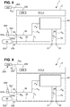
- the trailer control module 1 is shown in detail according to a first embodiment.
- the electro-pneumatic trailer control module 1 has a housing 2 in which an electronic control unit ECU and a trailer control valve unit 65 are arranged.
- the trailer control valve unit 65 has a plurality of valves, which are described in detail below.
- a supply inlet 11 is formed on the housing 2 and is connected to the third compressed air supply 525 via a supply pressure supply line 526.
- a redundancy pressure connection 42 to which a redundancy pressure supply line 552 is connected
- a parking brake pressure input 43 to which a parking brake pressure line 550 is connected, which in this exemplary embodiment is in turn connected to the electropneumatic handbrake unit (EPH) 541 (cf. Fig.
- the trailer control module 1 also has two pneumatic outputs, namely on the one hand a trailer supply pressure connection 21, to which the supply pressure P V is applied, and a trailer brake pressure connection 22, at which a brake pressure P B can be controlled.
- a supply pressure distribution line 50 runs from the supply inlet 11, via which various components of the trailer control module 1 are supplied with supply pressure P V.
- the trailer control valve unit 65 has an inlet-outlet valve unit 66, also referred to as a pilot control unit, which has an inlet valve IV, an outlet valve OV and a switching valve, designed here as a redundancy valve RV. Furthermore, the trailer control valve unit 65 has a first relay valve 20 which is not designed as an inverse relay valve, but rather as a "normal relay valve”.
- the inlet valve IV is designed as a 2/2-way valve and has a first inlet valve connection 67a and a second inlet valve connection 67b.
- the first inlet valve connection 67a is connected to a first supply pressure branch line 68 branching off from the supply distribution line, and the second inlet valve connection 67b is connected to a first control line 69.
- a service brake control pressure (first control pressure) P 1 can be controlled in the first control line 69 by electrically switching the inlet valve IV based on a signal S 1 from the control unit ECU.
- the first control line 69 is connected to a relay valve control input 25 of the relay valve 20.
- the relay valve 20 also has a relay valve working input 23, a relay valve output 24 and a relay valve venting output 26.
- the relay valve vent outlet 26 is connected to a pressure sink 3.
- the relay valve working input 23 serves to receive a supply pressure P V and is initially connected to a second supply pressure branch line 71, which is connected to a first connection 72a of a trailer demolition valve 73.
- the trailer demolition valve 73 is designed as a pneumatically switched 2/2-way valve and open without pressure, in which in Fig. 2 switching position shown.
- the first connection 72a of the trailer demolition valve 73 is connected via a throttle to the second connection 72b of the trailer demolition valve 73, which in turn is connected to the supply pressure distribution line 50 via a third supply pressure branch line 74.
- the trailer demolition valve 73 is in the in Fig. 2 position shown, so that the supply pressure P V is applied to the relay valve working input 23.
- the trailer supply connection 21 is also supplied with supply pressure P V by means of a trailer supply line 86.
- the relay valve 20 If the relay valve 20 now receives the service brake control pressure P 1 at the relay valve control input 25, the relay valve 20 controls a corresponding relay working pressure P 2 at the relay valve output 24 and provides this via a trailer brake pressure line 75 to the trailer brake pressure connection 22 as brake pressure P B .
- a brake pressure sensor 76 is provided for the trailer control module 1, which is connected to the trailer brake pressure line 75 via a brake pressure measurement line 77 and provides a corresponding pressure signal S DA to the control unit ECU.
- the outlet valve OV is switched electro-pneumatically and upon receipt of a signal S 2 from the control unit ECU from the first in Fig. 2 de-energized switching state shown, in which it is closed, to an open switching state, which is shown in Fig. 2 is not shown, relocatable.
- the outlet valve OV is provided for venting the service brakes 510a, 510b of the trailer truck 504 and thus for reducing a brake pressure P B at the trailer brake pressure connection 22.
- the outlet valve OV like the inlet valve IV, is designed as a 2/2-way valve and has a first outlet valve port 78a and a second outlet valve port 78b.
- the first outlet valve connection 78a is connected to the first control line 69 and the second outlet valve connection 78b to a pressure sink 3.
- inlet and outlet valves IV / OV are integrated and designed as a 3/2-way valve, a first connection being connected to the first supply pressure branch line 68, a second connection to the first control line 69 and a third connection to the pressure sink 3.
- the trailer control module 1 has the redundancy pressure connection 42.
- a brake signal transmitter is connected to the redundancy pressure connection 42 via a redundancy pressure supply line 552 528 connected (cf. Fig. 1 ).
- a first redundancy pressure line 16 is connected to the redundancy pressure connection 42 inside the housing 2.
- the redundancy pressure line 16 runs to a pneumatic switching valve 13, more precisely it is with a first connection 14a of the switching valve 13 (which will be described in more detail below).
- the switching valve 13 is in the second switching position, not shown, and the first connection 14a is in connection with the third connection 14c.
- a second redundancy pressure line 17 is then connected to a third connection 14c of the switching valve 13, which in turn is connected to a first redundancy valve connection 80a of a redundancy valve RV.
- the second redundancy valve connection 80b is connected to a redundancy pressure control line 81 which opens into the first control line 69 and thus into the relay valve control input 25 of the relay valve 20.
- the redundancy valve RV is designed as a 2/2-way valve and has a first and a second switching position, it being shown in FIG Fig. 2 is shown in the first open switch position.
- the redundancy valve RV is open when de-energized and also serves to be able to control a brake pressure P B in the event of a fault in which the inlet-outlet valve unit 66 is de-energized.
- a redundancy pressure P R is controlled in the redundancy pressure supply line 552 by pressing the pedal 590 of the brake value transmitter 528, this redundancy pressure P R is applied via the first redundancy pressure line 16, the switching valve 13, the second redundancy pressure line 17, the open redundancy valve RV and the redundancy pressure control line 81 the relay valve control input 25 of the relay valve 20 is provided.
- the brake pressure P B is then controlled at the relay valve output 24 of the relay valve 20.
- a parking brake valve unit 12 provided with the pneumatically controlled switching valve 13, which is designed as a 3/2-way valve 14 and which has a pneumatic control input 15 for receiving a pneumatic control pressure P 3 , the pneumatically controlled switching valve 13 when the parking brake pressure input 43 is connected to the pressure sink 3, that is, when the parking brake 6 is vented, it is switched in such a way that a brake pressure P B at the trailer brake pressure connection 22 can be controlled.
- the third connection 14c is connected to the second connection 14b, to which a fourth supply pressure branch line 41 is connected, which in turn branches off from the supply pressure distribution line 50 and to which the supply pressure P V is applied.
- the particular advantage here is that an inverse relay piston does not have to be used, but rather the pneumatically controlled switching valve 13 is switched based on the control pressure P 3 , which in particular is independent of a flowing current.
- the parking brake pressure P P at the parking brake pressure input 43 is preferably used as the control pressure P 3 .
- This is in the specific embodiment shown in Fig. 2 is shown, released by a pneumatic control line 83 which connects the parking brake pressure input 43 to the control input 15 of the pneumatically controlled switching valve 13. That is to say, in this embodiment with an electropneumatic handbrake, the pressure of the spring accumulator 6 is applied to the control input 15 of the pneumatically controlled switching valve 13.
- the control pressure of the trailer connection of the parking brake valve in the driver's cab is preferably connected to the parking brake pressure input 43. This is then used to control the supply pressure in the first switch position (driving position), control the ambient pressure in the second switch position (parking position) and control the supply pressure in the third switch position (trailer control position).
- the pneumatically controlled switching valve 13 is in the second switching position, not shown, and the brake pressure is controlled P B at the trailer brake pressure connection 22 is prevented in this switching position.
- the spring accumulators 6 are pressurized, and thus the pneumatically controlled 3/2-way valve 14 is in the second (not shown) switching position, and the redundancy pressure P R is controlled at the third connection 14c (if one is specified).
- the redundancy valve RV is already de-energized in this status and is thus opened, and as a result the fourth control pressure P 4 is applied to the relay valve control input 25 of the relay valve 20. In this way, a corresponding brake pressure P B is controlled at the trailer brake pressure connection 22.
- the redundancy valve RV when parking begins or the parking brake is applied in stages, the redundancy valve RV is initially energized with the signal S 3 and closed; the control pressure P 4 output by the switching valve 13 is initially locked out.
- the application of the service brakes 510a, 510b of the trailer 504 is implemented at the beginning of the parking via the inlet / outlet valve unit 66, which is switched accordingly by the control unit ECU. That is, if, for example, the handbrake switch 534 is actuated, the redundancy valve RV initially remains closed.
- the control unit ECU switches the inlet valve IV so that the service brake control pressure P 1 is applied to the relay valve control input 25 and a corresponding brake pressure P B is controlled at the trailer brake pressure connection 22, while the spring accumulator 6 is gradually venting and develop their braking power.
- all valves RV, IV, OV of the inlet-outlet valve unit 66 are de-energized; the inlet valve IV closes while the redundancy valve RV is opened.
- the fourth control pressure P 4 is now applied to the relay valve control input 25 via the switching valve 13 and the redundancy valve RV and the braking pressure P B is controlled; the service brakes 510a, 510b of the trailer 504 remain engaged.
- the trailer control module 1 also has a first CAN bus connection 30 to which the first CAN bus line 554 is connected.
- This first CAN bus connection 30 is designed as an input 31 for a trailer control position signal S K. Since in this embodiment ( Fig. 1 , 2 ) an electropneumatic handbrake (EPH) is provided, the trailer control position signal S K is transmitted electronically.
- EPH electropneumatic handbrake
- the trailer control position signal S K is transmitted electronically.
- European trailer control for which the trailer control module 1 according to the first exemplary embodiment ( Fig. 2 ) is provided, it is necessary that the vehicle driver can engage a trailer control position.
- the trailer control position is used to check whether the vehicle train 500 is standing safely solely on the basis of the parking brakes 6, 532a, 532b of the towing vehicle 502.
- the control unit ECU is set up to process the trailer control position signal S K and to send a corresponding switching signal S 3 to the redundancy valve RV, so that the redundancy valve RV is in the second, in Fig. 2 switch position not shown switches so that the control pressure P 4 is locked out.
- the outlet valve OV must be opened briefly in order to vent any pressure that is currently locked in. In this case, there is no service brake control pressure P 1 at the relay valve control input 25, and no brake pressure P B is output at the trailer brake pressure connection 22.
- the parking brake valve (not shown) of the driver's cab via which the vehicle driver requests the parking position and also the trailer control position, is preferably connected to the parking brake pressure input 43 . If the vehicle driver selects the trailer control position by means of the parking brake valve, a control pressure is output at the parking brake pressure input 43, so that the switching valve 13 in the in Figure 2 The second switching position, not shown, remains and accordingly no control pressure P 4 is controlled. Consequently, no parking brake pressure P B is output at the trailer brake pressure connection 22 either. Thus the position of the trailer can be checked.
- the control unit ECU in this embodiment also has a parking brake signal input 200 for receiving a first electronic brake representation signal S B1 , which represents the actuation of a parking brake 6, 532a, 532b of the towing vehicle 502.
- the parking brake signal input 200 is in this embodiment ( Fig. 2 ) connected to a second CAN bus connection 202 to which a second CAN bus line 204 is connected, which in turn is connected to the central module 527.
- the first brake representation signal S B1 is in this case an electronic signal that is provided by the central module 527.
- the first brake representation signal S B1 represents braking by means of the parking brakes 6, 532a, 532b and, in a simple embodiment, can be the signal that the central module 527 sends to the handbrake unit 541.
- the first brake representation signal S B1 is one of them derived signal or an independent signal that is provided by the central module 527.
- the control unit ECU is set up to switch at least one valve, preferably the inlet valve IV, based on the received first brake representation signal S B1 by means of a signal S 1 , so that a brake pressure P B is controlled at the trailer brake pressure connection 22.
- a brake pressure P B is controlled at the trailer brake pressure connection 22.
- the relay valve 20 then controls a relay working pressure P 2 at the relay valve output 24, so that the brake pressure P B is applied to the trailer brake pressure connection 22.
- a particularly simple integration of the trailer control module 1 into an existing towing vehicle 502 is achieved. It is not necessary to provide an additional valve or the like in order to achieve a connection between the electropneumatic handbrake unit (EPH) 541 and the trailer control module 1. Rather, it is sufficient to provide a corresponding second CAN bus line 204 from the central module 527 to the second CAN bus connection 202, so that the first brake representation signal S B1 can be provided at the parking brake signal input 200.
- EPH electropneumatic handbrake unit
- the electro-pneumatic trailer control module 1 according to this embodiment ( Fig. 2 ), more precisely the electronic control unit ECU, also has a further connection 250 for receiving a redundant electronic brake representation signal S B4 .
- a redundant electronic brake representation signal S B4 can, for example, in addition to the usual received deceleration request signal for the service brakes 510a, 510b of the trailer 504 may be a redundant electronic signal controlled by a manual brake value transmitter 528.
- the braking value transmitter 528 has a position transmitter which converts an actuation of the pedal 590 into an electronic signal.
- connection 250 is connected to a signal line 252.
- Electropneumatic trailer control module 1 optionally has a CAN bus connection 202a (cf. Fig. 1 ), to which a CAN bus 555 is connected, which leads to the parking brake unit 541.
- the trailer control module 1 can also receive the redundant electronic brake representation signal S B4 via this CAN bus 555 in the event of a fault.
- the trailer control module 1 has an additional (in the Figure 2 not shown; see. Figure 7 and 10 ) Pressure sensor which redundantly detects the redundant pressure P R and provides a corresponding pressure signal S DR as the redundant brake representation signal S B4 at the connection 250.
- FIG. 3 to 9 now show further exemplary embodiments of the electro-pneumatic trailer control module, the trailer control valve unit 65 only being shown schematically as a "black box".
- the trailer control valve unit can in the embodiments of Figures 3 to 9 be designed as in the embodiment of Fig. 2 .
- the corresponding line connections are designated below. Identical and similar elements are provided with the same reference symbols, so that reference is made in full to the above description.
- a first difference in the embodiment according to FIG Fig. 3 to the embodiment according to Fig. 2 lies in the design of the pneumatically controlled switching valve 13.
- the third connection 14c of the switching valve 13 is connected to a first shuttle valve inlet 18a of a shuttle valve 18.
- the shuttle valve 18 is preferably designed as a double-acting check valve 19, that is to say as a so-called select high valve.
- the shuttle valve 18 has a second shuttle valve inlet 18b.
- the respective higher pressure at the shuttle valve inlets 18a, 18b is at the shuttle valve outlet 18c controlled.
- the first redundancy pressure line 16 is in this embodiment ( Fig. 3 ) not connected directly to the first connection 14a of the switching valve 13, but to the second shuttle valve inlet 18b.
- the in Fig. 3 In the in Fig.
- the depressurized switching position of the switching valve 13 shown is thus applied to the first changeover valve inlet 18a, the supply pressure P V , while the redundancy pressure P R is applied to the second changeover valve inlet 18b.
- a control pressure P 4 is output into the second redundancy pressure line 17, which is connected to the shuttle valve outlet 18c.
- the control pressure P 4 is the respective higher pressure of the supply pressure P V and the redundancy pressure P R.
- the parking brakes of the tractor 502 are released, so that a control pressure P 3 is applied to the control input 15 of the switching valve 13.
- the switching valve 13 is then in the in Fig. 3 second switching position, not shown, in which the first connection 14a is connected to the third connection 14c.
- the first connection 14a is in this exemplary embodiment ( Fig. 3 ) connected to a pressure sink 3. That is, during normal driving operation, ambient pressure P 0 is present at port 14c, so that only redundancy pressure P R can be output into second redundancy pressure line 17 as control pressure P 4 via shuttle valve 18. If the parking brakes of the towing vehicle are now applied, that is to say the spring accumulator 6 is vented, the switching valve 13 switches to the in Fig. 3 position shown. A control pressure P 4 is consequently output in the second redundancy pressure line 17, which leads to a braking pressure P B being output at the trailer brake pressure connection 22. The service brakes of trailer vehicle 504 are applied.
- the parking brake signal input 200 is designed to be connected to a pressure sensor 208.
- the pressure sensor 208 is designed as an external pressure sensor 209.
- the external pressure sensor 209 is connected to a pressure sensor connection 206 on the housing 2 of the trailer control module 1 by means of a signal line 210.
- the parking brake signal input 200 is in connection with the pressure sensor connection 206, so that the parking brake signal input 200 receives a signal from the external Pressure sensor 209 can receive.
- the external pressure sensor 209 preferably detects the pressure on a parking brake, in particular the pressure on a cylinder 6a of a spring accumulator 6, in order to provide a corresponding pressure signal S D as a second brake representation signal S B2 at the pressure sensor connection 206 and thus at the parking brake signal input 200.
- the external pressure sensor 209 can ultimately be installed somewhere in the train carriage 502. This makes it possible to achieve a particularly simple integration of the trailer control module 1 into an existing towing vehicle 502, especially with a conventional pneumatic parking brake. It is only necessary to lay a signal line from an existing external pressure sensor 209 to the pressure sensor connection 206 so that the brake representation signal S B2 can be provided in the form of the pressure signal S D at the parking brake signal input 200.
- the further functioning of the trailer control module 1 according to the second exemplary embodiment ( Fig. 3 ) is identical to that of the first exemplary embodiment ( Fig. 2 ).
- the third embodiment ( Fig. 4 ) is a combination of the first and second exemplary embodiment. While the parking brake valve unit 12 in the third embodiment ( Fig. 4 ) according to the second embodiment ( Fig. 2 ), the parking brake signal input 200 is according to the first embodiment ( Fig. 2 ) connected to the second CAN bus connection 202, to which the second CAN bus line 204 is connected, which in turn runs to the central module 527. In this respect, the above description of the Fig. 2 and 3 referenced.
- the parking brake signal input 200 is in turn designed to be connected to a pressure sensor 208.
- the pressure sensor 208 is designed as an internal pressure sensor 212.
- the parking brake signal input 200 is connected to the internal pressure sensor 212 via an internal interface 214.
- the internal pressure sensor 212 is connected via a measuring line 216 to the pneumatic control line 83, in which the control pressure P 3 is controlled via the parking brake pressure input 43.
- the internal pressure sensor 212 detects the parking brake pressure output at the parking brake pressure input 43, which corresponds to the brake pressure in the parking brakes, in particular spring accumulators 6, or an equivalent pressure of a pilot control unit for the parking brakes or the pressure that is output by a parking brake valve on the trailer connection.
- the internal pressure sensor 212 provides a pressure signal S DI at the internal interface 214, which is provided at the parking brake signal input 200 as a third brake representation signal S B3 .
- the pressure signal S DI thus forms the brake representation signal S B3 according to the fourth and fifth exemplary embodiments.
- the trailer control module 1 according to the fourth and fifth exemplary embodiments is identical to the first three exemplary embodiments. Again, it is a trailer control module 1 for a “European trailer control”, and to this extent the trailer control module has the parking brake valve unit 12.
- the parking brake valve unit 12 according to the fourth embodiment ( Fig. 5 ) corresponding to the second and third exemplary embodiment ( Fig. 3 and 4th ) is formed, the parking brake valve unit 12 in the fifth embodiment ( Fig. 6 ) according to the first embodiment ( Fig. 2 ) educated. That is, in the fourth embodiment ( Fig. 5 ) the control pressure P 4 is controlled via the shuttle valve 18, while in the fifth embodiment ( Fig. 6 ) a direct modulation of the control pressure P 4 via the 3/2-way valve 14 takes place.
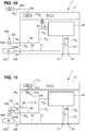
- Fig. 7 now illustrates a sixth embodiment, which is basically based on the fifth embodiment ( Fig. 6 ) builds up. Identical and similar elements are provided with the same reference numerals and in this respect reference is made in full to the above description.
- the redundant pressure sensor 90 is connected to the first redundancy pressure line 16 via a redundancy pressure measuring line 91. As a result, the redundant pressure sensor 90 measures the redundant pressure P R in the first redundancy pressure line 16, which is controlled manually by actuating the brake pedal 590 at the redundancy pressure connection 42.
- the manually controlled redundancy pressure P R via the first redundancy pressure line 16 possibly the shuttle valve 18, the second redundancy pressure line 17, the redundancy valve RV, the redundancy pressure control line 81 and the relay valve 20 (cf. Fig. 2 ) leads to a brake pressure P B controlled at the trailer brake pressure connection 22.
- the redundant pressure sensor 90 can be used to detect a driver interaction with autonomous control of the brake system 520.
- the redundant pressure sensor 90 measures the manually controlled redundancy pressure P R and provides a corresponding redundancy pressure signal S DR to the control unit ECU.
- the redundancy pressure signal S DR provided by the redundant pressure sensor 90 represents a driver's request, since the redundant pressure sensor 90 detects the redundancy pressure P R controlled manually by means of the braking value transmitter 528.
- the control unit ECU is preferably set up to compare the redundancy pressure signal S DR , which it receives from the pressure sensor 90, with an autonomously controlled operating brake signal, which it receives, for example, from the control unit 536 for autonomous driving.
- the control unit ECU causes the redundancy valve RV to be switched in order, based on the redundancy pressure P R, to manually control a brake pressure P B at the trailer brake pressure connection 22 to enable.
- the control unit 536 is locked out and the driver takes over manually.
- the embodiments seven, eight, nine and ten now each show a trailer control module 1 for the "Scandinavian trailer control".
- the embodiments seven, eight, nine and ten differ therefore differ from the previous exemplary embodiments essentially in that they do not have a parking brake valve unit 12, since in the "Scandinavian trailer control" the control of a brake pressure P B at the trailer brake pressure connection 22 in the event that the parking brakes of the towing vehicle 502 are engaged should only take place temporarily , and the service brakes of the trailer are then released again in the parking position.
- the parking brake signal input 200 of the trailer control module 1 is set up to receive the brake representation signal S B1 from the central module 527.
- the electro-pneumatic trailer control module 1 can also send the brake representation signal S B1 via the third CAN bus 555 and the CAN bus termination 202a (cf. Fig. 1 ) received directly from the electronic control unit of the parking brake unit 541.
- the parking brake signal input 200 is designed to receive a pressure signal S D as a brake representation signal S B2 from a pressure sensor 208, in this case an external pressure sensor 209.
- a pressure sensor 208 in this case an external pressure sensor 209.
- the ninth embodiment ( Fig. 10 ) is again based on the seventh embodiment ( Fig. 8 ), but includes, like the sixth embodiment ( Fig. 7 ) a redundant pressure sensor 90.
- a redundant pressure sensor 90 For a detailed description of the redundant pressure sensor 90, reference is made to the above description of the sixth embodiment ( Fig. 7 ) referenced.
- the parking brake signal input 200 is designed to receive the brake representation signal SB3 as a pressure signal S DI from a pressure sensor 208, in this case an internal pressure sensor 212, to receive.
- a pressure sensor 208 in this case an internal pressure sensor 212
- the parking brake signal input 200 is designed accordingly.
- FIGS Figures 12 and 13 now illustrate further variants of the trailer control valve unit 65, and it can be seen that the trailer control valve unit 65 according to FIGS Figures 12 and 13 those from the Figures 2 to 11 can replace each.
- the redundancy valve RV is designed as a 3/2-way valve 120.
- the main difference lies in the interconnection of the redundancy valve RV, which is designed as a 3/2-way valve 120.
- Another difference lies in the reversal of the outlet valve OV, which is reversed in the switching positions so that it is open when de-energized, as in FIG Fig. 10 switching position shown.
- the outlet valve is ( Fig. 2 ) with its second outlet valve port 78b is not connected directly to the pressure sink 3, but to a first connecting line 122 which connects the second outlet valve port 78b to the second redundancy valve port 80b.
- the third redundancy valve connection 80c of the 3/2-way valve 120 is connected to the pressure sink 3 via a further vent branch line 124.
- the mode of operation of this layout is as follows: In normal driving operation, the outlet valve OV is switched into the second, closed switching position, not shown, based on a signal S 2 provided by the control unit ECU. A service brake control pressure P 1 at the relay valve control input 25 of the relay valve 20 can then be controlled by switching the inlet valve IV based on the signal S 1 of the electronic control unit ECU, and based on this, in turn, a relay working pressure P 2 at the relay valve output 24 The redundancy valve RV is also in the Normal driving mode in the second shift position, not shown, based on a signal S 3 . In the currentless state (as in Fig.
- the first redundancy valve port 80a is connected to the second redundancy valve port 80b, so that the redundancy pressure P R can be controlled in the first connecting line 122.
- the redundancy pressure P R is locked out, and so the signal S 3 is applied in order to bring the redundancy valve RV into the second switching position, not shown.
- the second redundancy valve connection 80b is connected to the third redundancy valve connection 80c. That is, in the second switching position, not shown, of the redundancy valve RV, the pressure sink 3 is connected to the second outlet valve port 78b. Consequently, the relay valve control input 25 can be vented into the de-energized position via a corresponding switching of the outlet valve OV, so as not to control any brake pressure P B at the trailer brake pressure connection 22.
- a second variant is in Fig. 13 shown. Even with the in Fig. 13 The variant of the trailer control valve unit 65 shown here, the redundancy valve RV is designed as a 3/2-way valve 120.
- the first redundancy valve connection 80a is in turn connected to the redundancy pressure connection 42 via the first redundancy pressure line 16.
- the second redundancy valve connection 80b is, as is also the case in the first exemplary embodiment ( Fig. 2 ) is the case with a pneumatic line, here a second connecting line 126 connected.
- the third redundancy valve connection 80c is connected to the first supply pressure branch line 68.
- the second connecting line 126 is also connected to the first inlet valve port 67a and the second inlet valve port 67b is connected to the first control line 69, as is also the case in the first exemplary embodiment.
- the mode of operation of this circuit layout is as follows: In the de-energized state, that is to say without signal S 3 , the redundancy valve RV is in the in Fig. 13 first switch position shown. In the first currentless switching position, the first redundancy valve connection 80a is connected to the second redundancy valve connection 80b. In the de-energized position, a redundancy pressure P R can therefore be controlled on the second connecting line 126. During normal driving operation, however, a signal S 3 is switched so that the third redundancy valve connection 80c is connected to the second redundancy valve connection 80b and the supply pressure P V is controlled on the second connecting line 126.
- Inlet valve IV is normally open and in the first switching position (in Fig. 13 shown), the outlet valve OV is normally closed and in the first switching position (in Fig. 13 shown). During normal driving, the inlet valve IV is closed and a signal S 1 is present. If the inlet valve IV is now opened, the service brake control pressure P 1 can flow from the supply inlet 11 via the first supply branch line 68, the third redundancy valve connection 80c, the second redundancy valve connection 80b, the second connecting line 126, the first inlet valve connection 67a, the second inlet valve connection 67b and the first control line 69 can be controlled at the relay valve control input 25, which in turn controls a brake pressure P B at the trailer brake pressure connection 22.
- the electronic control unit ECU then sends a signal S 2 to the outlet valve OV, so that it is switched to the second switching position (open switching position) while the inlet valve is in operation IV is placed in the closed second switching position with a signal S 1 .
- the relay valve control input 25 is therefore connected to the pressure sink 3 via the first control line 69, the first outlet valve connection 78a, the second outlet valve connection 78b and the vent branch line 79 and can be vented.
- the brake pressure P B decreases again.
- the position of the valves RV, IV, OV is selected such that, in the event that the control unit ECU fails, a redundancy pressure P R at the redundancy pressure connection 42 results in a brake pressure P B being output at the trailer brake pressure connection 22 .
- the redundancy valve RV connects the redundancy pressure connection 42 to the second connecting line 126.
- the inlet valve IV is open when de-energized and the redundancy pressure P R can reach the first control line 69 via the inlet valve IV.
- the outlet valve OV is closed and blocks the first control line 69 from the pressure sink 3.
- the redundancy pressure PR is applied to the relay valve control input 25 and a brake pressure P B can be controlled at the trailer brake pressure connection 22.
- the relay valve 20 is different from the prior art, with a common control chamber 100, in this embodiment only a single control chamber 100, (cf. Fig. 14 ) educated.
- the relay valve 20 has a relay valve control input 25, the relay valve working input 23, to which the second supply pressure branch line 71 of the supply pressure distribution line 50 is connected and to which the pressure P V is applied, a relay valve output 24 which is supplied via the trailer brake pressure line 75 is connected to the trailer brake pressure connection 22 and via which the relay working pressure P 2 or the brake pressure P B can be controlled, as well as a relay valve venting output 26, through which the relay valve output 24 can be vented and which is connected to the pressure sink 3 .
- a pressure P 0 is consequently present at the relay valve vent outlet 26, which corresponds to the pressure of the pressure sink 3, in particular the environment.
- the relay valve 20 has a common control chamber 100 into which the single relay valve control inlet 25 opens. It can be provided that further control inputs open into the control chamber 100. Both the service brake control pressure P 1 and the redundancy pressure P R can be controlled into the common control chamber 100 via the relay valve control input 25; in this respect, only one common control chamber 100 is provided for the two control pressures P 1 , P R.
- the control chamber 100 thus fulfills two functions: on the one hand, the brake pressure P B can be controlled as a function of the service brake control pressure P 1 by means of the control chamber 100, and on the other hand, the brake pressure P B can also be controlled as a function of the redundancy pressure P R by means of the control chamber 100.
- the control chamber 100 acts on a single control piston 102.
- the single control piston 102 is guided along an axis A in an axially sliding manner.
- the control piston 102 can move with respect to Fig. 14 move downward and comes with a valve seat 104 in contact with a corresponding slide ring 106, which is spring-loaded into the axially upper position.
- a spiral spring 108 is provided for this purpose.
- the sliding ring 106 has a second valve seat 110, which seals against a projection 112 and thus initially keeps the relay valve operating inlet 23 closed.
- the control piston is in Fig. 14 shown in an open position. In its closing position, the valve seat 104 is in contact with the sliding ring 106. In the closing position, both the relay valve work inlet 23 and the relay valve outlet 24 are closed off from the relay valve vent outlet 26.
- a force acts on the control piston 102, which leads to the opening of the second valve seat 110 so that the pressure P V can jump into the working chamber 114.
- the pressure in the working chamber 114 rises and leads to a counterforce on the control piston 102, so that the control piston moves back into the closing position.
- a brake pressure P B is controlled at the relay valve output 24 and held there.
- Figure 15 now shows an eleventh embodiment. Basically it's similar in Figure 15 Brake system 520 shown corresponding to that Figure 1 and the same and similar elements are provided with the same reference symbols. In this respect, the above description of the Fig.1 Referenced. The following therefore essentially deals with the differences. The difference lies in the interconnection in the layout of the brake system 520; This change has little or no influence on the electro-pneumatic trailer control module 1.
- the redundancy connection 42 is not connected via the redundancy pressure supply line 552 to the bypass 553 and via this to the braking value transmitter 528; rather, the brake pressure of another vehicle axle, in this exemplary embodiment the front axle brake pressure P BV , is controlled at the redundancy connection 42.
- a third redundancy pressure supply line 694 is provided, which is connected to a front axle brake pressure line 693 via a T-piece 692.
- the front axle brake pressure P BV of the service brakes 530a, 530b of the front axle at the redundancy pressure connection 42 is controlled via this third redundancy pressure supply line 694.
- the braking value transmitter 528 is then different from the first embodiment ( Fig. 1 ) connected only to the bypass 533 and connected via this to the front axle modulator 529 in order to control the brake signal transmitter control pressure P BST redundantly at the front axle modulator 529.
- the brake signal transmitter control pressure P BST which is controlled manually by means of the foot pedal 590 Front axle modulator 529 to be controlled as redundancy pressure P R at redundancy pressure connection 42 of electropneumatic control module 1.
Description
Die Erfindung betrifft ein elektropneumatisches Anhängersteuermodul für ein elektronisch steuerbares pneumatisches Bremssystem für einen Fahrzeugzug mit einem Zugwagen und einem Anhängerwagen, mit einem elektronischen Steuergerät, einem pneumatischen Vorratseingang, der mit einem Druckluftvorrat verbindbar ist, einer Anhängersteuer-Ventileinheit mit einem oder mehreren elektropneumatischen Ventilen, einem Anhängerbremsdruckanschluss und einem Anhängerversorgungsdruckanschluss. Die Erfindung betrifft ferner einen Fahrzeugzug mit einem elektropneumatischen Anhängersteuermodul der vorstehenden Gattung.The invention relates to an electro-pneumatic trailer control module for an electronically controllable pneumatic brake system for a vehicle train with a towing vehicle and a trailer, with an electronic control device, a pneumatic supply input that can be connected to a compressed air supply, a trailer control valve unit with one or more electro-pneumatic valves, a Trailer brake pressure connection and a trailer supply pressure connection. The invention also relates to a vehicle train with an electropneumatic trailer control module of the above type.
In Fahrzeugen, insbesondere Nutzfahrzeugen, mit einem pneumatischen Bremssystem, insbesondere ausgebildet als elektronisches Bremssystem (EBS) oder Antiblockiersystem (ABS) können zum Aussteuern von Bremsdrücken von einem Steuergerät (ECU) elektropneumatische Ventile, beispielsweise Relaisventile oder Achsmodulatoren, angesteuert werden, die dann in Abhängigkeit einer angeforderten Fahrzeug-Soll-Verzögerung pneumatisch einen Bremsdruck an die Bremszylinder von Betriebsbremsen des Bremssystems weiterleiten.In vehicles, in particular commercial vehicles, with a pneumatic brake system, in particular designed as an electronic brake system (EBS) or anti-lock braking system (ABS), electropneumatic valves, for example relay valves or axle modulators, can be activated by a control unit (ECU) to control brake pressures a requested vehicle target deceleration pneumatically forward a brake pressure to the brake cylinders of the service brakes of the brake system.
Bei Bremssystemen für einen Fahrzeugzug weist das Bremssystem eine Anhängersteuereinheit, auch Trailer Control Valve (TCV) genannt, auf, die dazu vorgesehen ist, die von dem Zugwagen vorgegebenen Fahrzeug-Soll-Verzögerungen entsprechend auch über Anschlüsse, nämlich einen Anhängerbremsdruckanschluss und einen Anhängerversorgungsdruckanschluss, die auch als gelber und roter Kupplungskopf bezeichnet werden, pneumatisch auszusteuern. Über den Anhängerversorgungsdruckanschluss wird der Anhängerwagen mit einem Versorgungsdruck aus einem dafür vorgesehenen Vorrat des Zugwagens versorgt, während über den Anhängerbremsdruckanschluss der entsprechende Bremsdruck ausgesteuert wird.In the case of brake systems for a vehicle train, the brake system has a trailer control unit, also called a Trailer Control Valve (TCV), which is provided for the purpose of applying the target vehicle decelerations specified by the towing vehicle via connections, namely a trailer brake pressure connection and a trailer supply pressure connection, which also known as yellow and red coupling heads, pneumatic to control. The trailer is supplied with a supply pressure from a supply of the towing vehicle provided for this purpose via the trailer supply pressure connection, while the corresponding brake pressure is controlled via the trailer brake pressure connection.
Als ein weiteres Bauteil oder Modul weisen Bremssysteme der vorstehenden Gattung eine Feststellbremseinheit, insbesondere eine elektropneumatische Handbremse (EPH) oder eine konventionelle rein pneumatische Feststellbremseinheit, auf. Solche Feststellbremseinheiten werden üblicherweise mit sogenannten Federspeichern betrieben, also Bremseinrichtungen, die aufgrund einer Federkraft eine oder mehrere Achsen des Zufahrzeugs bremsen. Im belüfteten Zustand sind die Bremsen gelöst und im entlüfteten Zustand gebremst. In einem drucklosen Zustand wird das entsprechende Fahrzeug also gebremst. Zur Aktivierung der Feststellbremseinheit ist im Falle einer elektropneumatischen Handbremse (EPH) in der Regel in der Fahrerkabine des Zugwagens ein elektrischer Handbremsschalter vorgesehen, über den ein entsprechendes Signal an eine elektronische Steuereinheit ausgebbar ist, die dann ein oder mehrere elektropneumatische Ventile so schaltet, dass die Federspeicher entweder ent- oder belüftet werden. Bei konventionellen rein pneumatischen Feststellbremseinheiten ist in der Regel in der Fahrerkabine ein Ventil vorgesehen, über das bei entsprechender Schaltung ein Steuerdruck zum ent- oder belüften der Federspeicher aussteuerbar ist.As a further component or module, brake systems of the above type have a parking brake unit, in particular an electropneumatic handbrake (EPH) or a conventional, purely pneumatic parking brake unit. Such parking brake units are usually operated with so-called spring accumulators, that is to say braking devices that brake one or more axles of the approach vehicle due to a spring force. The brakes are released in the ventilated state and braked in the vented state. In a pressureless state, the corresponding vehicle is therefore braked. To activate the parking brake unit, in the case of an electropneumatic handbrake (EPH), an electric handbrake switch is usually provided in the driver's cab of the towing vehicle, via which a corresponding signal can be output to an electronic control unit, which then switches one or more electropneumatic valves so that the Spring accumulator can be either vented or pressurized. In the case of conventional, purely pneumatic parking brake units, a valve is generally provided in the driver's cab, via which a control pressure for venting or ventilating the spring accumulator can be controlled when appropriately switched.
Die Feststellbremseinheit, also die elektropneumatische Handbremse, wird zum Parken des Fahrzeugzugs aber auch als Zusatzbremse in besonderen Situationen verwendet. Das heißt, neben dem normalen Betriebsbremsen werden die Federspeicher wenigstens teilweise entlüftet, um diese zusätzlich oder alternativ zur Bremsung zu verwenden. Um hier ein entsprechendes Bremssignal auch für den Anhängerwagen pneumatisch auszusteuern, wird in der Regel ein sogenanntes inverses Relaisventil verwendet, welches basierend auf einem sinkenden Druck in den Federspeichern einen steigenden Druck aussteuert. Solche inversen Relaisventile sind in ihrer Bauart aufwendig und weisen mehrere Steuerkolben auf, die über verschiedene Steuerflächen und verschiedene Steuerkammern miteinander interagieren. So wird z. B. bei einem reinen Hilfsbremsen ausschließlich über Federspeicher im Zugwagen und Betriebsbremsen im Anhängerwagen gebremst. Die Betriebsbremsen im Zugwagen sind beim reinen Hilfsbremsen unbetätigt. Alternativ kann auch ein Redundanzmodus umgesetzt werden, wo z. B. bei einem Kreisausfall an der Hinterachse alternativ zu den Betriebsbremsen die Federspeicher zur Hilfe genommen werden. Die Vorderachse kann weiterhin über Betriebsbremsen gebremst werden, und der Anhängerwagen ebenfalls über Betriebsbremsen.The parking brake unit, i.e. the electropneumatic handbrake, is used to park the vehicle train but also as an additional brake in special situations. That is, in addition to the normal service brakes, the spring accumulators are at least partially vented in order to use them in addition or as an alternative to braking. In order to pneumatically control a corresponding brake signal for the trailer, a so-called inverse relay valve is used as a rule, which controls an increasing pressure based on a falling pressure in the spring accumulators. Such inverse relay valves are complex in their design and have several control pistons that have different control surfaces and different control chambers interact with each other. So z. B. with a pure auxiliary brakes braked exclusively via spring accumulators in the towing vehicle and service brakes in the trailer. The service brakes in the towing vehicle are not activated when the brakes are purely auxiliary. Alternatively, a redundancy mode can also be implemented, where e.g. B. in the event of a circuit failure on the rear axle, the spring accumulator can be used as an alternative to the service brakes. The front axle can still be braked using service brakes, and the trailer can also be braked using service brakes.
Ferner wird bei Bremssystemen der eingangs genannten Art zwischen der sogenannten "europäischen Anhängersteuerung" und der "skandinavischen Anhängersteuerung" unterschieden. Während bei der "europäischen Anhängersteuerung" im geparkten Zustand des Fahrzeugzugs ein den entlüfteten Federspeichern entsprechender positiver Bremsdruck an dem Anhängerwagen ausgesteuert wird, um diesen zusätzlich mittels der Anhängerbetriebsbremsen zu bremsen, ist bei der "skandinavischen Anhängersteuerung" das Gegenteil der Fall: Im abgestellten Zustand des Fahrzeugzugs sollen die Betriebsbremsen des Anhängerwagens gelöst sein. Das bedeutet, bei der "europäischen Anhängersteuerung" muss im abgestellten Zustand des Fahrzeugzugs, also im stromlosen Zustand, permanent ein positiver Bremsdruck über die Anhängersteuereinheit (TCV) an die Betriebsbremsen des Anhängerwagens ausgesteuert werden.Furthermore, a distinction is made between the so-called "European trailer control" and the "Scandinavian trailer control" in brake systems of the type mentioned at the beginning. While with the "European trailer control" when the vehicle train is parked, a positive brake pressure corresponding to the vented spring accumulators is applied to the trailer in order to additionally brake it using the trailer service brakes, the opposite is the case with the "Scandinavian trailer control": When the The trailer vehicle's service brakes should be released. This means that with the "European trailer control", when the vehicle combination is parked, i.e. when the vehicle is switched off, a positive brake pressure must be continuously applied to the trailer vehicle's service brakes via the trailer control unit (TCV).
Da in der Praxis also die Anhängersteuereinheit (TCV) und die Feststellbremseinheit (EPH) interagieren, hat sich eine Integration dieser beiden Module als wünschenswert herausgestellt. Ein erster Ansatz der Integration ist beispielsweise in
Auf ähnliche Weise schlägt auch
Eine praktische Ausführung für die "skandinavische Anhängersteuerung" ist in
Ferner ist aus
Darüber hinaus existieren streng modulare Ansätze, die es erlauben die Module zusammenzubringen, die für den jeweiligen Anwendungsfall benötigt werden. Ein solches System ist aus
Ein heutzutage wichtiger Aspekt ist auch die Nachrüstbarkeit einzelner Module und Komponenten oder deren Austausch. Daher ist ein integrierter Ansatz, wie er beispielsweise in
Daher ist es eine Aufgabe der vorliegenden Erfindung, ein elektropneumatisches Anhängersteuermodul anzugeben, bei dem die oben genannten Funktionalitäten, insbesondere in Bezug auf die "skandinavische" und die "europäische Anhängersteuerung", als auch ein Hilfsbremsen des Anhängerwagens möglich ist. Das Anhängersteuermodul soll klein im Bauraum, kostengünstig und wenig fehleranfällig sein.It is therefore an object of the present invention to provide an electro-pneumatic trailer control module in which the above-mentioned functionalities, in particular with regard to the "Scandinavian" and the "European Trailer control ", as well as auxiliary braking of the trailer vehicle is possible. The trailer control module should be small in terms of installation space, inexpensive and less prone to errors.
Diese Aufgabe wird bei einem elektropneumatischen Anhängersteuermodul nach Anspruch 1 gelöst, wobei das elektronische Steuergerät einen Parkbremssignal-Eingang zum Aufnehmen eines elektronischen Bremsrepräsentationssignals, das die Betätigung einer Feststellbremse des Zugwagens repräsentiert, aufweist, wobei die elektronische Steuereinheit dazu eingerichtet ist, basierend auf dem Bremsrepräsentationssignal wenigstens ein Ventil des einen oder der mehreren elektropneumatischen Ventile der Anhängersteuer-Ventileinheit zu schalten, um einen Bremsdruck an dem Anhängerbremsdruckanschluss auszusteuern. Auf diese Weise lässt sich das elektropneumatische Anhängersteuermodul einfach in ein bestehendes Zugwagen eines Fahrzeugzugs einbauen. Es ist nicht erforderlich, die vorhandene elektropneumatische Handbremse oder auch die konventionelle rein pneumatische Feststellbremseinheit auszutauschen. Es ist lediglich erforderlich, eine Verbindung zwischen einem anderen Steuergerät, beispielsweise der elektropneumatischen Handbremse, einem übergeordneten Steuergerät, einem Zentralmodul oder einem anderen Peripheriegerät, welches mit der Betätigung einer Feststellbremse befasst ist bzw. ein entsprechendes Signal erhält oder sendet und dem elektropneumatischen Anhängersteuermodul der vorliegenden Erfindung in Kommunikation zu bringen.This object is achieved with an electro-pneumatic trailer control module according to
Als Bremsrepräsentationssignal wird vorliegend ein Signal verstanden, das ein tatsächliches Bremsen mittels der Feststellbremsen bzw. Parkbremsen oder eine Bremsanforderung für die Feststellbremsen bzw. Parkbremsen repräsentiert. Ein solches Bremsrepräsentationssignal kann direkt von einem weiteren Steuergerät, beispielsweise einem Zentralmodul (etwa über CAN-Bus), oder einen Handbremsschalter (etwa über LIN-Bus) bereitgestellt werden. In einer Variante kann es auch ein elektronisches Signal eines Drucksensors sein, der einen Bremsdruck erfasst. Der Drucksensor kann intern, das heißt innerhalb des elektropneumatischen Anhängersteuermoduls, angeordnet sein oder extern zu diesem.In the present case, a brake representation signal is understood to be a signal that represents actual braking by means of the parking brakes or parking brakes or a braking request for the parking brakes or parking brakes. Such a brake representation signal can be provided directly by a further control device, for example a central module (for example via CAN bus) or a handbrake switch (for example via LIN bus). In one variant, it can also be an electronic signal from a pressure sensor that detects a brake pressure. The pressure sensor can be internal, that is, within of the electro-pneumatic trailer control module, or external to this.
Der Parkbremssignal-Eingang ist vorzugsweise an der elektronischen Steuereinheit (ECU) ausgebildet.The parking brake signal input is preferably formed on the electronic control unit (ECU).
Aufgrund der besonderen Gestaltung der elektronischen Steuereinheit mit dem Parkbremssignal-Eingang ist das elektropneumatische Anhängersteuermodul der vorliegenden Erfindung dazu in der Lage, sowohl ein Hilfsbremsen mittels der Betriebsbremsen des Anhängerwagens für den Fall auszuführen, dass die Feststellbremsen des Zugwagens als Hilfsbremse verwendet werden, als auch ein Parkbremsen mittels der Betriebsbremsen, wenn eine europäische Anhängersteuerung umgesetzt wird. Das elektropneumatische Anhängersteuermodul der vorliegenden Erfindung ist also dazu in der Lage, ein einfaches Nachrüsten dieser Funktionalitäten zu erlauben, ohne zu stark in den bestehenden Zugwagen einzugreifen.Due to the special design of the electronic control unit with the parking brake signal input, the electro-pneumatic trailer control module of the present invention is able to perform both an auxiliary braking by means of the service brakes of the trailer in the event that the parking brakes of the towing vehicle are used as an auxiliary brake, as well as a Parking brakes using the service brakes if a European trailer control is implemented. The electro-pneumatic trailer control module of the present invention is therefore able to allow these functionalities to be easily retrofitted without interfering too much in the existing towing vehicle.
Gemäß einer ersten bevorzugten Ausführungsform weist die Anhängersteuer-Ventileinheit wenigstens ein Einlassventil mit einem ersten Einlassventilanschluss und einem zweiten Einlassventilanschluss auf, wobei der erste Einlassventilanschluss mit dem Vorratseingang verbunden ist und die elektronische Steuereinheit dazu eingerichtet ist, basierend auf dem Bremsrepräsentationssignal das Einlassventil zu schalten, um einen Bremsdruck an dem Anhängerbremsdruckanschluss auszusteuern. Das Einlassventil kann beispielsweise als 2/2-Wegeventil ausgebildet sein mit einem ersten und einem zweiten Schaltzustand, wobei das Einlassventil vorzugsweise stromlos im ersten Schaltzustand verbleibt. In einer Alternative kann das Einlassventil auch als 3/2-Wegeventil ausgebildet sein und somit gleichzeitig eine weitere Funktionalität, wie beispielsweise ein Entlüften, ausüben.According to a first preferred embodiment, the trailer control valve unit has at least one inlet valve with a first inlet valve port and a second inlet valve port, the first inlet valve port being connected to the supply inlet and the electronic control unit being set up to switch the inlet valve based on the brake representation signal to control a brake pressure at the trailer brake pressure connection. The inlet valve can for example be designed as a 2/2-way valve with a first and a second switching state, the inlet valve preferably remaining in the first switching state without current. In an alternative, the inlet valve can also be designed as a 3/2-way valve and thus simultaneously exercise a further functionality, such as for example venting.
In einer weiteren bevorzugten Ausführungsform ist die elektronische Steuereinheit dazu eingerichtet das Bremsrepräsentationssignal von einer weiteren Steuereinheit zu empfangen. Diese weitere Steuereinheit ist nicht die elektronische Steuereinheit (ECU) des elektropneumatischen Anhängersteuermoduls. In einer ersten Alternative ist die weitere Steuereinheit eine elektronische Steuereinheit einer Feststellbremseinheit. In einer zweiten Alternative ist die weitere Steuereinheit ein Zentralmodul.In a further preferred embodiment, the electronic control unit is set up to receive the brake representation signal from a further control unit. This additional control unit is not the electronic control unit (ECU) of the electro-pneumatic trailer control module. In a In the first alternative, the further control unit is an electronic control unit of a parking brake unit. In a second alternative, the further control unit is a central module.
Das Zentralmodul ist dasjenige Modul, das zentral das Bremssystem steuert und welches üblicherweise ein entsprechendes Betriebsbremssignal an die eine oder die mehreren Betriebsbremsen des Zugwagens bereitstellt. Das Zentralmodul stellt darüber hinaus üblicherweise eine Hilfsbremsanforderung bereit, für den Fall, dass die Feststellbremsen zum Hilfsbremsen eingesetzt werden sollen. Daher ist es eine besonders einfache Lösung, wenn die elektronische Steuereinheit dazu eingerichtet ist, das Bremsrepräsentationssignal von dem Zentralmodul zu empfangen. Vorzugsweise ist ein Betriebsbremssignal-Eingang und/oder der Parkbremssignal-Eingang dazu mit einem entsprechenden Ausgang des Zentralmoduls verbunden. Das von dem Zentralmodul bereitgestellte Bremsrepräsentationssignal ist in diesem Fall ein elektronisches Signal und kann dasselbe Signal sein, welches zum Hilfsbremsen an die Feststellbremsen bzw. die elektropneumatische Feststellbremseinheit des Zugwagens gesendet wird, oder ein entsprechendes oder ein abgeleitetes Signal. Es kann auch vorgesehen sein, dass das Zentralmodul ein separates, eigens für den Anhängerwagen vorgesehenes Bremssignal sendet, welches in diesem Fall dann das Bremsrepräsentationssignal bildet.The central module is that module which controls the brake system centrally and which usually provides a corresponding service brake signal to the one or more service brakes of the towing vehicle. The central module also usually provides an auxiliary brake request in the event that the parking brakes are to be used for auxiliary braking. It is therefore a particularly simple solution if the electronic control unit is set up to receive the brake representation signal from the central module. For this purpose, a service brake signal input and / or the parking brake signal input are preferably connected to a corresponding output of the central module. The brake representation signal provided by the central module is in this case an electronic signal and can be the same signal that is sent to the parking brakes or the electropneumatic parking brake unit of the towing vehicle for auxiliary braking, or a corresponding or a derived signal. It can also be provided that the central module sends a separate brake signal which is provided specifically for the trailer, which in this case then forms the brake representation signal.
Die Feststellbremseinheit steuert die Feststellbremsen, die insbesondere Federspeicher umfassen. Die Feststellbremseinheit stellt in einer Alternative das Bremsrepräsentationssignal an dem Parkbremssignal-Eingang des elektropneumatischen Anhängersteuermoduls bereit. Diese Ausführungsform ist insbesondere dann bevorzugt, wenn in dem Bremssystem eine Rückfallebene für den Fall des Ausfalls des Zentralmoduls geschaffen werden soll. In diesem Fall ist es gemäß dieser Ausführungsform möglich, den Anhänger in Abhängigkeit der Feststellbremsen zu bremsen.The parking brake unit controls the parking brakes, which in particular include spring accumulators. In one alternative, the parking brake unit provides the brake representation signal at the parking brake signal input of the electro-pneumatic trailer control module. This embodiment is particularly preferred when a fallback level is to be created in the brake system in the event of failure of the central module. In this case, according to this embodiment, it is possible to brake the trailer as a function of the parking brakes.
Erfindungsgemäß ist der Parkbremssignal-Eingang dazu ausgebildet, mit einem Drucksensor verbunden zu werden, wobei die elektronische Steuereinheit dazu eingerichtet ist, das elektronische Bremsrepräsentationssignal von diesem Drucksensor zu empfangen. In diesem Fall bildet das elektronische Drucksignal, das von dem Drucksensor bereitgestellt wird, das Bremsrepräsentationssignal. Der Drucksensor ist vorzugsweise dazu eingerichtet, einen Bremsdruck von wenigstens einer Feststellbremse zu erfassen, vorzugsweise einen Druck in einem Zylinder eines Federspeichers des Zugwagens. Alternativ ist der Drucksensor dazu eingerichtet, einen Druck einer Vorsteuereinheit einer elektropneumatischen Handbremseinheit (EPH) oder einer konventionellen rein pneumatischen Feststellbremseinheit des Zugwagens zu erfassen, insbesondere einen Steuerdruck, der zur Aussteuerung eines Bremsdrucks an der wenigstens einen Feststellbremse, insbesondere dem Federspeicher, dient. Bei einer konventionellen rein pneumatischen Feststellbremseinheit mit europäischer Anhängeransteuerung kann auch ein pneumatischer Anhängerparkbremsdruck durch den Drucksensor erfasst werden.According to the invention, the parking brake signal input is designed to be connected to a pressure sensor, the electronic control unit being designed to send the electronic brake representation signal to receive from this pressure sensor. In this case, the electronic pressure signal which is provided by the pressure sensor forms the brake representation signal. The pressure sensor is preferably set up to detect a brake pressure of at least one parking brake, preferably a pressure in a cylinder of a spring accumulator of the towing vehicle. Alternatively, the pressure sensor is set up to detect a pressure of a pilot control unit of an electropneumatic handbrake unit (EPH) or a conventional, purely pneumatic parking brake unit of the towing vehicle, in particular a control pressure that is used to control a brake pressure on the at least one parking brake, in particular the spring brake. In the case of a conventional, purely pneumatic parking brake unit with European trailer control, a pneumatic trailer parking brake pressure can also be recorded by the pressure sensor.
Gemäß einer bevorzugten Variante weist das elektropneumatische Anhängersteuermodul einen Parkbremsdruckeingang zum Empfang eines Drucks einer pneumatischen Feststellbremse des Zugwagens auf. Hierbei ist besonders bevorzugt, dass das elektropneumatische Anhängersteuermodul den Drucksensor aufweist, wobei der Drucksensor den Druck an dem Parkbremsdruckeingang des Anhängersteuermoduls erfasst und mit dem Parkbremssignal-Eingang verbunden ist, um ein elektronisches Drucksignal als Bremsrepräsentationssignal an dem Steuergerät bereitzustellen. Auf diese Weise lässt sich das elektropneumatische Anhängersteuermodul noch einfacher in einen Zugwagen integrieren. Es ist nicht erforderlich, dass das elektropneumatische Anhängersteuermodul durch eine elektrische Signalleitung mit einer übergeordneten Einheit, beispielsweise dem Zentralmodul, verbunden ist und diese übergeordnete Steuereinheit dazu in der Lage ist, ein elektronisches Bremsrepräsentationssignal bereitzustellen. Vielmehr ist es ausreichend, eine pneumatische Leitung von einer Feststellbremse oder einer der Feststellbremse vorgeschalteten Vorsteuereinheit zu dem elektropneumatischen Anhängersteuermodul zu führen, sodass der Druck an dem Parkbremsdruckeingang mittels des internen Drucksensors des Anhängersteuermoduls erfasst werden kann.According to a preferred variant, the electro-pneumatic trailer control module has a parking brake pressure input for receiving a pressure from a pneumatic parking brake of the towing vehicle. It is particularly preferred that the electro-pneumatic trailer control module has the pressure sensor, the pressure sensor detecting the pressure at the parking brake pressure input of the trailer control module and being connected to the parking brake signal input in order to provide an electronic pressure signal as a brake representation signal to the control unit. In this way, the electro-pneumatic trailer control module can be integrated into a towing vehicle even more easily. It is not necessary for the electro-pneumatic trailer control module to be connected to a superordinate unit, for example the central module, by an electrical signal line and for this superordinate control unit to be able to provide an electronic brake representation signal. Rather, it is sufficient to lead a pneumatic line from a parking brake or a pilot control unit upstream of the parking brake to the electropneumatic trailer control module so that the pressure at the parking brake pressure input can be detected by means of the internal pressure sensor of the trailer control module.
Erfindungsgemäß weist das Anhängersteuermodul eine Parkbremsventileinheit mit einem pneumatisch gesteuerten Schaltventil auf, welches einen pneumatischen Steuereingang zum Aufnehmen eines pneumatischen Steuerdrucks aufweist, wobei das pneumatisch gesteuerte Schaltventil bei Entlüftung des Parkbremsdruckeingangs so geschaltet wird, dass ein Bremsdruck an dem Anhängerbremsdruckanschluss aussteuerbar ist. Die Parkbremsventileinheit dient also dazu, bei Entlüftung der Federspeicher, also bei Einlegen der Feststellbremsen, einen korrespondierenden Bremsdruck an dem Anhängerbremsdruckanschluss auszusteuern, um die Betriebsbremsen des Anhängerwagens einzubremsen. Dies ist insbesondere für die sogenannte "europäische Anhängersteuerung" von Vorteil, um in einem geparkten Zustand des Zugwagens stromlos nur auf Basis eines pneumatischen Steuerdrucks den Anhängerwagen zu bremsen.According to the invention, the trailer control module has a parking brake valve unit with a pneumatically controlled switching valve, which has a pneumatic control input for receiving a pneumatic control pressure, the pneumatically controlled switching valve being switched when the parking brake pressure input is vented so that a brake pressure at the trailer brake pressure connection can be controlled. The parking brake valve unit thus serves to control a corresponding brake pressure at the trailer brake pressure connection when the spring accumulator is vented, ie when the parking brakes are engaged, in order to apply the brake on the service brakes of the trailer vehicle. This is of particular advantage for the so-called “European trailer control”, in order to brake the trailer in a parked state of the towing vehicle without current only on the basis of a pneumatic control pressure.
Dementsprechend ist der pneumatische Steuerdruck in einer ersten Ausführungsform der Druck an dem Federspeicher-Anschluss. Solange also die Federspeicher gelöst sind und Zylinder der Federspeicher belüftet sind, ist das pneumatisch gesteuerte Schaltventil in der zweiten Schaltstellung, und wenn der Federspeicher-Anschluss mit einer Drucksenke verbunden ist und die Federspeicher entlüftet sind, wird das pneumatisch gesteuerte Schaltventil aufgrund der Federbelastung in die zweite Schaltstellung verbracht.Accordingly, in a first embodiment, the pneumatic control pressure is the pressure at the spring-loaded connection. As long as the spring accumulators are released and the cylinders of the spring accumulators are pressurized, the pneumatically controlled switching valve is in the second switching position, and when the spring accumulator connection is connected to a pressure sink and the spring accumulators are vented, the pneumatically controlled switching valve is in the second switch position spent.
Alternativ ist es in einer weiteren Ausführungsform möglich, dass der pneumatische Steuerdruck ein Feststellbrems-Steuerdruck in einer vorgeschalteten Vorsteuereinheit der Feststellbremseinheit ist. Es kann also ebenso ein dem Druck an dem Federspeicher-Anschluss entsprechender bzw. äquivalenter Druck verwendet werden, wie insbesondere ein Steuerdruck für die Feststellbremsen. Zum Beispiel ist es möglich, den Steuerdruck an einem Relaisventil der Feststellbremseinheit, sowohl einer elektropneumatischen Handbremse (EPH) als auch einer konventionellen rein pneumatischen Feststellbremseinheit, zu verwenden. Bei einer konventionellen rein pneumatischen Feststellbremseinheit mit europäischer Anhängeransteuerung kann es auch ein pneumatischer Anhängerparkbremsdruck sein. Es ist also möglich, sowohl den Arbeitsdruck, der tatsächlich an wenigstens einem der Federspeicher anliegt, als Steuerdruck für das pneumatisch gesteuerte Schaltventil zu verwenden, als auch einen den Arbeitsdruck der Federspeicher aussteuernden Steuerdruck.Alternatively, in a further embodiment it is possible that the pneumatic control pressure is a parking brake control pressure in an upstream pilot control unit of the parking brake unit. A pressure which corresponds or is equivalent to the pressure at the spring-loaded connection can also be used, such as, in particular, a control pressure for the parking brakes. For example, it is possible to use the control pressure on a relay valve of the parking brake unit, both an electropneumatic handbrake (EPH) and a conventional, purely pneumatic parking brake unit. In the case of a conventional, purely pneumatic parking brake unit with European trailer control, it can also be a pneumatic trailer parking brake pressure. So it is possible both the work pressure, the actually applied to at least one of the spring accumulators, to be used as a control pressure for the pneumatically controlled switching valve, as well as a control pressure which modulates the working pressure of the spring accumulator.
In einer weiteren bevorzugten Ausführungsform weist das elektropneumatische Steuergerät einen Redundanzdruckanschluss mit einer ersten Redundanzdruckleitung zum Anschluss eines Bremswertgebers oder des Brems- oder Steuerdrucks einer der anderen Fahrzeugachsen, über den z. B. durch Betätigung eines Bremspedals ein pneumatischer Bremsdruck am Anhängerbremsdruckanschluss aussteuerbar ist. Der Bremswertgeber kann rein pneumatisch, elektropneumatisch oder auf sonstige Weise ausgebildet sein. Der Redundanzdruckanschluss dient dazu, eine Fahrzeug-Soll-Verzögerung eines Fahrzeugführers zu empfangen, die dieser mittels des Bremswertgebers manuell einsteuert. Der Fahrzeugführer kann so in einem Fehlerfall, z. B. bei Ausfall der Versorgungsspannung rein pneumatisch einen Bremsdruck aussteuern. Alternativ wird an dem Redundanzdruckanschluss ein Brems- oder Steuerdruck einer anderen Fahrzeugachse, z. B. der Vorderachse, ausgesteuert. Hierdurch kann dann im Fehlerfall der Anhängerwagen in Übereinstimmung mit der anderen Achse gebremst werden.In a further preferred embodiment, the electropneumatic control device has a redundancy pressure connection with a first redundancy pressure line for connecting a brake value transmitter or the brake or control pressure of one of the other vehicle axles, via the z. B. a pneumatic brake pressure at the trailer brake pressure connection can be controlled by pressing a brake pedal. The brake signal transmitter can be designed purely pneumatically, electropneumatically or in some other way. The redundancy pressure connection is used to receive a target vehicle deceleration from a vehicle driver, which the driver manually controls by means of the brake value transmitter. In the event of an error, the vehicle driver can B. if the supply voltage fails, control a brake pressure purely pneumatically. Alternatively, a brake or control pressure from another vehicle axle, e.g. B. the front axle, controlled. In this way, in the event of a fault, the trailer can be braked in accordance with the other axle.
In einer bevorzugten Ausführungsform ist vorgesehen, dass das pneumatisch gesteuerte Schaltventil mit einem Auslass mit einer zweiten Redundanzdruckleitung verbunden ist, mit welcher auch die erste Redundanzdruckleitung verbindbar ist, sodass bei Schalten des pneumatisch gesteuerten Schaltventils ein Druck in die zweite Redundanzdruckleitung aussteuerbar ist. Vorzugsweise ist folglich durch Schalten des pneumatisch gesteuerten Schaltventils ein pneumatischer Bremsdruck am Anhängerbremsdruckanschluss aussteuerbar. In der Redundanzdruckleitung ist vorzugsweise ein Redundanzventil angeordnet, welches beispielsweise als 2/2-Wegeventil ausgebildet sein kann. Das Redundanzventil wird dazu verwendet den Redundanzdruck im üblichen Fahrbetrieb auszusperren. Indem das pneumatisch gesteuerte Schaltventil den Druck in die zweite Redundanzdruckleitung aussteuert, kann das (nachgeschaltete) Redundanzventil dazu eingesetzt werden den von dem pneumatisch gesteuerten Schaltventil ausgesteuerten Druck auszusperren. Hierdurch ist es möglich eine "Anhängerkontrollstellung" auszuführen, wie dies weiter unten noch genauer beschrieben werden wird. Weiterhin wird hierdurch die Bauweise und das Layout weiter vereinfacht, da nur eine Leitung, nämlich die zweite Redundanzdruckleitung, verwendet wird, um sowohl den Redundanzdruck als auch den Druck aus dem pneumatisch gesteuerten Schaltventil (Parkbremsdruck) auszusteuern. Es hat sich gezeigt, dass dies möglich ist, da der Redundanzdruck nur dann ausgesteuert wird, wenn der Fahrzeugzug im Betrieb ist, der Parkbremsdruck aber nur dann, wenn der Fahrzeugzug geparkt wird. Hierdurch werden Bauteile eingespart, und der Aufbau kann kompakter gestaltet werden.In a preferred embodiment it is provided that the pneumatically controlled switching valve is connected to an outlet with a second redundancy pressure line, to which the first redundancy pressure line can also be connected, so that when the pneumatically controlled switching valve is switched, a pressure in the second redundancy pressure line can be controlled. Consequently, a pneumatic brake pressure at the trailer brake pressure connection can preferably be controlled by switching the pneumatically controlled switching valve. In the redundancy pressure line, a redundancy valve is preferably arranged, which can be designed as a 2/2-way valve, for example. The redundancy valve is used to lock out the redundancy pressure during normal driving. Since the pneumatically controlled switching valve controls the pressure in the second redundancy pressure line, the (downstream) redundancy valve can be used for that of the pneumatically controlled one Lock out switching valve controlled pressure. This makes it possible to carry out a "trailer control position", as will be described in more detail below. This further simplifies the construction and layout, since only one line, namely the second redundancy pressure line, is used to control both the redundancy pressure and the pressure from the pneumatically controlled switching valve (parking brake pressure). It has been shown that this is possible because the redundancy pressure is only controlled when the vehicle train is in operation, but the parking brake pressure only when the vehicle train is parked. This saves components and the structure can be made more compact.
Weiterhin ist bevorzugt, dass das pneumatisch gesteuerte Schaltventil als 3/2-Wegeventil mit einem ersten, einem zweiten und einem dritten Anschluss ausgebildet ist. Der dritte Anschluss ist vorzugsweise wie oben beschrieben mit der zweiten Redundanzdruckleitung verbunden und als Auslass ausgebildet.It is also preferred that the pneumatically controlled switching valve is designed as a 3/2-way valve with a first, a second and a third connection. The third connection is preferably connected to the second redundancy pressure line, as described above, and is designed as an outlet.
In einer bevorzugten Variante ist der erste Anschluss des 3/2-Wegeventils mit dem Redundanzdruckanschluss und der zweite Anschluss des 3/2-Wegeventils mit dem Vorratseingang verbunden. Das 3/2-Wegeventil schaltet also in dieser Variante zwischen dem Redundanzdruckanschluss und dem Vorratseingang abhängig von dem pneumatischen Steuerdruck am Steuereingang hin und her und steuert diesen Druck in die zweite Redundanzdruckleitung aus. Der erste Anschluss des 3/2-Wegeventils ist vorzugsweise über die erste Redundanzdruckleitung mit dem Redundanzdruckanschluss verbunden. Werden folglich die Federspeicher entlüftet, schaltet das 3/2-Wegeventil aufgrund des sinkenden Steuerdrucks an dem Steuereingang auf die erste Schaltstellung, sodass der Vorratseingang mit der zweiten Redundanzdruckleitung verbunden ist. Im Fall der Entlüftung der Federspeicher ist somit das Aussteuern eines manuell eingegebenen Redundanzdrucks nicht möglich; der Redundanzdruckanschluss ist mit dem ersten Anschluss des 3/2-Wegeventils verbunden, der in diesem Schaltzustand gesperrt ist.In a preferred variant, the first connection of the 3/2-way valve is connected to the redundancy pressure connection and the second connection of the 3/2-way valve is connected to the supply inlet. In this variant, the 3/2-way valve switches back and forth between the redundancy pressure connection and the supply input depending on the pneumatic control pressure at the control input and controls this pressure in the second redundancy pressure line. The first connection of the 3/2-way valve is preferably connected to the redundancy pressure connection via the first redundancy pressure line. If the spring accumulators are consequently vented, the 3/2-way valve switches to the first switching position due to the falling control pressure at the control input, so that the supply input is connected to the second redundancy pressure line. When the spring accumulator is vented, it is therefore not possible to control a manually entered redundancy pressure; the redundancy pressure connection is connected to the first connection of the 3/2-way valve, which is blocked in this switching state.
In einer zweiten Variante ist der erste Anschluss des pneumatisch gesteuerten 3/2-Wegeventils mit einer Drucksenke verbunden. In dieser Variante schaltet das 3/2-Wegeventil zwischen dem Vorratseingang und der Drucksenke hin und her, sodass die zweite Redundanzdruckleitung, die mit dem dritten Anschluss des pneumatisch gesteuerten 3/2-Wegeventils verbunden ist, bei entsprechender Schaltstellung des 3/2-Wegeventils entlüftbar ist. Der Redundanzdruckanschluss kann in dieser Variante über ein zweites Ventil, beispielsweise ein 2/2-Wegeventil, mit der zweiten Redundanzdruckleitung verbunden sein.In a second variant, the first connection of the pneumatically controlled 3/2-way valve is connected to a pressure sink. In this variant switches the 3/2-way valve back and forth between the supply inlet and the pressure sink, so that the second redundancy pressure line, which is connected to the third connection of the pneumatically controlled 3/2-way valve, can be vented when the 3/2-way valve is in the corresponding switch position. In this variant, the redundancy pressure connection can be connected to the second redundancy pressure line via a second valve, for example a 2/2-way valve.
Besonders bevorzugt ist, dass der dritte Anschluss des pneumatisch gesteuerten 3/2-Wegeventils mit einem ersten Wechselventileingang eines Wechselventils verbunden ist, ein zweiter Wechselventileingang des Wechselventils mit dem Redundanzdruckanschluss verbunden ist und ein Wechselventilausgang des Wechselventils mit der zweiten Redundanzdruckleitung verbunden ist. Das Wechselventil ist vorzugsweise als sogenanntes Select-High-Ventil ausgebildet mit einem doppelwirkenden Rückschlagventil. Dies bedeutet, an dem Wechselventilausgang wird stets der höhere Druck, der an dem ersten und zweiten Wechselventileingang anliegt, ausgesteuert. In dieser Variante ist es möglich, trotz eingelegter oder teilweise eingelegter Parkbremse, wenn diese beispielsweise als Hilfsbremse verwendet wird, einen Redundanzdruck manuell auszusteuern und den Druck, der durch das pneumatisch gesteuerte 3/2-Wegeventil ausgesteuert wird, über das Wechselventil zu übersteuern. Hierdurch ist es möglich, auf ein weiteres 2/2-Wegeventil oder ein anderes Layout zu verzichten. Ein Wechselventil ist ein relativ kleines Bauteil, welches vorzugsweise mit dem pneumatisch gesteuerten 3/2-Wegeventil integriert ist.It is particularly preferred that the third connection of the pneumatically controlled 3/2-way valve is connected to a first changeover valve input of a changeover valve, a second changeover valve input of the changeover valve is connected to the redundancy pressure connection and a changeover valve output of the changeover valve is connected to the second redundancy pressure line. The shuttle valve is preferably designed as a so-called select high valve with a double-acting check valve. This means that the higher pressure that is present at the first and second shuttle valve inlet is always controlled at the shuttle valve outlet. In this variant it is possible to manually control a redundancy pressure and to override the pressure that is controlled by the pneumatically controlled 3/2-way valve via the shuttle valve, in spite of the applied or partially applied parking brake, if this is used, for example, as an auxiliary brake. This makes it possible to do without another 2/2-way valve or another layout. A shuttle valve is a relatively small component that is preferably integrated with the pneumatically controlled 3/2-way valve.
In einer bevorzugten Weiterbildung ist vorgesehen, dass zwischen einem Auslass des pneumatisch gesteuerten Schaltventils und dem Anhängerbremsdruckanschluss ein elektronisches Schaltventil angeordnet ist, sodass bei Verbinden des Federspeicher-Anschlusses mit der Drucksenke ein Aussteuern eines Bremsdrucks an dem Anhängerbremsdruckanschluss unterbunden werden kann. Das elektronische Schaltventil ist vorzugsweise als 3/2-Wegeventil oder 2/2-Wegeventil ausgebildet. Es ist vorzugsweise in einer stromlosen Stellung offen. Durch das elektronische Schaltventil lässt sich der Auslass des pneumatisch gesteuerten Schaltventils sperren. Ist der Auslass gesperrt, wird kein Bremsdruck an dem Anhängerbremsdruckanschluss ausgesteuert. Der Auslass des pneumatisch gesteuerten Schaltventils ist vorzugsweise der dritte Anschluss des pneumatisch gesteuerten 3/2-Wegeventils, wenn das pneumatisch gesteuerte Schaltventil als 3/2-Wegeventil ausgebildet ist.In a preferred development, it is provided that an electronic switching valve is arranged between an outlet of the pneumatically controlled switching valve and the trailer brake pressure connection, so that when the spring-loaded connection is connected to the pressure sink, modulation of a brake pressure at the trailer brake pressure connection can be prevented. The electronic switching valve is preferably designed as a 3/2-way valve or 2/2-way valve. It is preferably open in a de-energized position. The outlet of the pneumatically controlled switching valve can be blocked by the electronic switching valve. If the outlet is blocked, no Brake pressure controlled at the trailer brake pressure connection. The outlet of the pneumatically controlled switching valve is preferably the third connection of the pneumatically controlled 3/2-way valve if the pneumatically controlled switching valve is designed as a 3/2-way valve.
Die vorstehende Variante ist besonders dann bevorzugt, wenn die Ausführung einer sogenannten "Anhängerkontrollstellung" gewünscht ist. Eine Anhängerkontrollstellung dient dazu zu prüfen, ob der Fahrzeugzug auch ohne eingelegte Betriebsbremsen in dem Anhängerwagen allein durch die Federspeicher im Zugwagen steht. Ist beispielsweise der Fahrzeugzug an einer Stelle mit leichtem Gefälle abgestellt, soll der Fahrer eine Anhängerkontrollstellung einlegen können, um dies zu prüfen. Dies dient der Sicherheit, falls aufgrund einer Leckage die Bremskraft der Betriebsbremsen über die Zeit nachlässt, wenn der Fahrzeugzug über längere Zeit abgestellt ist. Zur Einlegung der "Anhängerkontrollstellung" betätigt der Fahrer im Falle einer elektropneumatischen Handbremse (EPH) vorzugsweise einen entsprechenden Schalter, der über die Steuereinheit (ECU) veranlasst, dass das elektronische Schaltventil geschaltet wird und den Auslass des pneumatisch gesteuerten Schaltventils sperrt. Nach einer vorbestimmten Zeit wird das elektronische Schaltventil wieder freigegeben und in die offene Stellung geschaltet, vorzugsweise stromlos, sodass dann an dem Anhängerbremsdruckanschluss ein Bremsdruck ausgesteuert wird, der zum Einlegen der Betriebsbremsen des Anhängers verwendet werden kann. Auf ähnliche Weise kann dies bei einer konventionellen rein pneumatischen Feststellbremseinheit gelöst werden. Hierbei kann einerseits ein elektrischer Schalter für die Anhängerkontrollstellung vorgesehen sein, oder das Parkbremsventil zur Betätigung der Feststellbremse in der Fahrerkabine weist eine dritte Schaltstellung für die Anhängerkontrollstellung auf. Das Parkbremsventil ist dazu ausgebildet zwei verschiedene Steuerdrücke auszusteuern: 1.) den Steuerdruck für die Federspeicher und 2.) den Steuerdruck für den Anhänger bzw. die Anhängersteuereinheit (TCV). In der dritten Schaltstellung des Parkbremsventils für die Anhängerkontrollstellung wird als Steuerdruck für die Federspeicher Umgebungsdruck ausgesteuert, und als Steuerdruck für den Anhänger bzw. die Anhängersteuereinheit (TCV) wird Vorratsdruck ausgesteuert. Hierdurch werden die Federspeicher zugespannt, während der Anhänger ungebremst bleibt (der Steuerdruck für den Anhänger wird in der Anhängersteuereinheit invertiert). Wird das Parkbremsventil nun in die Parkstellung gebracht, wird für die Anhängersteuereinheit derselbe Steuerdruck ausgesteuert, der auch für die Federspeicher ausgesteuert wird, in diesem Fall also Umgebungsdruck.The above variant is particularly preferred when the implementation of a so-called "trailer control position" is desired. A trailer control position is used to check whether the vehicle train is standing in the trailer vehicle even without the service brakes being applied by the spring accumulator in the towing vehicle. For example, if the vehicle train is parked at a point with a slight slope, the driver should be able to engage a trailer control position in order to check this. This is for safety if the braking force of the service brakes decreases over time due to a leak when the vehicle train is parked for a long time. In order to engage the "trailer control position", in the case of an electropneumatic handbrake (EPH), the driver preferably actuates a corresponding switch which, via the control unit (ECU), causes the electronic switching valve to be switched and the outlet of the pneumatically controlled switching valve to be blocked. After a predetermined time, the electronic switching valve is released again and switched to the open position, preferably without current, so that a brake pressure is then controlled at the trailer brake pressure connection that can be used to apply the service brakes of the trailer. In a similar way, this can be solved with a conventional purely pneumatic parking brake unit. Here, on the one hand, an electrical switch can be provided for the trailer control position, or the parking brake valve for actuating the parking brake in the driver's cab has a third switch position for the trailer control position. The parking brake valve is designed to control two different control pressures: 1.) the control pressure for the spring accumulator and 2.) the control pressure for the trailer or the trailer control unit (TCV). In the third switching position of the parking brake valve for the trailer control position, ambient pressure is controlled as control pressure for the spring accumulator, and supply pressure is controlled as control pressure for the trailer or the trailer control unit (TCV). As a result, the spring accumulators are tensioned while the trailer remains unbraked (the control pressure for the trailer is inverted in the trailer control unit). If the parking brake valve is now brought into the parking position, the same control pressure is applied to the trailer control unit that is also applied to the spring accumulator, in this case ambient pressure.
Eine bevorzugte Ausgestaltung sieht vor, dass die Anhängersteuereinheit ein Relaisventil aufweist, welches einen mit dem Vorratseingang verbundenen Relaisventil-Arbeitseingang, einen mit dem Anhängerbremsdruckanschluss verbundenen Relaisventil-Ausgang, einen Relaisventil-Entlüftungsausgang, über den der Relaisventil-Ausgang mit einer Drucksenke verbindbar ist, und einen Relaisventil-Steuereingang aufweist, der in eine gemeinsame innere Steuerkammer mündet, wobei der Relaisventil-Steuereingang über die Anhängersteuer-Ventileinheit mit dem Vorratseingang und/oder einer Drucksenke verbindbar ist, um einen Bremsdruck am Anhängerbremsdruckanschluss auszusteuern, wobei in die gemeinsame Steuerkammer sowohl ein Betriebsbrems-Steuerdruck, als auch ein Redundanzdruck aussteuerbar sind. Vorzugsweise weist das Relaisventil eine einzige Steuerkammer auf. Die Anhängersteuer-Ventileinheit weist dazu vorzugsweise ein Einlassventil und ein Auslassventil auf, wobei der Relaisventil-Steuereingang mittels des Einlassventils mit dem Vorratseingang verbindbar ist und mittels des Auslassventils mit der Drucksenke verbindbar ist. Einlass- und Auslassventil können jeweils als 2/2-Wegeventil ausgebildet sein, oder sie sind gemeinsam als 3/2-Wegeventil integriert. Durch diesen Aufbau wird ein besonders einfaches Relaisventil verwendet, welches nur eine einzige Steuerkammer aufweist. Es kann vorgesehen sein, dass mehrere Eingänge in diese Steuerkammer münden. Bevorzugt ist aber nur ein einziger Relaisventil-Steuereingang vorgesehen.A preferred embodiment provides that the trailer control unit has a relay valve which has a relay valve working input connected to the supply input, a relay valve output connected to the trailer brake pressure connection, a relay valve venting output via which the relay valve output can be connected to a pressure sink, and has a relay valve control input which opens into a common inner control chamber, the relay valve control input being connectable via the trailer control valve unit to the supply input and / or a pressure sink in order to control a brake pressure at the trailer brake pressure connection, with both a service brake in the common control chamber -Control pressure and a redundancy pressure can be controlled. The relay valve preferably has a single control chamber. For this purpose, the trailer control valve unit preferably has an inlet valve and an outlet valve, the relay valve control inlet being connectable to the supply inlet by means of the inlet valve and being connectable to the pressure sink by means of the outlet valve. The inlet and outlet valves can each be designed as a 2/2-way valve, or they are integrated together as a 3/2-way valve. With this structure, a particularly simple relay valve is used which has only a single control chamber. It can be provided that several inlets open into this control chamber. However, only a single relay valve control input is preferably provided.
Vorzugsweise ist die gemeinsame Steuerkammer des Relaisventils durch einen einzigen Steuerkolben begrenzt ist. Vorzugsweise weist das Relaisventil auch nur einen einzigen Steuerkolben auf. Hierdurch ist die Bauweise weiter vereinfacht, und Kosten werden reduziert.The common control chamber of the relay valve is preferably delimited by a single control piston. The relay valve preferably also has only a single control piston. This further simplifies the construction and reduces costs.
In einer bevorzugten Weiterbildung ist die Steuerkammer über ein elektronisch schaltbares Einlassventil mit dem Vorratseingang verbindbar. Vorzugsweise ist die Steuerkammer mit der zweiten Redundanzdruckleitung verbindbar. Hierzu ist es möglich, dass ein weiteres Ventil, beispielsweise ein elektronisch schaltbare 2/2-Wegeventil, vorgesehen ist. Varianten umfassen aber auch ein einfaches T-Stück, einen zweiten Relaisventil-Steuereingang, der in dieselbe Steuerkammer mündet, ein 3/2-Wegeventil oder ein Select-High-Ventil.In a preferred development, the control chamber can be connected to the supply inlet via an electronically switchable inlet valve. The control chamber can preferably be connected to the second redundancy pressure line. For this purpose, it is possible for a further valve, for example an electronically switchable 2/2-way valve, to be provided. Variants also include a simple T-piece, a second relay valve control inlet that opens into the same control chamber, a 3/2-way valve or a Select-High valve.
In einer Variante ist die Steuerkammer mit der ersten Redundanzdruckleitung verbunden. Vorzugsweise ist der Relaisventilsteuereingang mit der ersten Redundanzdruckleitung verbunden. Es kann vorgesehen sein, dass zwischen der ersten Redundanzdruckleitung und dem Relaisventilsteuereingang ein 2/2-Wegeventil vorgesehen ist, um den Redundanzdruck im normalen Fahrbetrieb aussperren zu können.In one variant, the control chamber is connected to the first redundancy pressure line. The relay valve control input is preferably connected to the first redundancy pressure line. Provision can be made for a 2/2-way valve to be provided between the first redundancy pressure line and the relay valve control input in order to be able to lock out the redundancy pressure during normal driving.
Gemäß einer weiteren bevorzugten Ausführungsform weist das elektropneumatische Anhängersteuermodul einen Eingang an der elektronischen Steuereinheit für ein Anhängerkontrollstellungs-Signal auf. Wie bereits weiter oben beschrieben ist bei der "europäischen Anhängersteuerung" bevorzugt, dass das Anhängersteuermodul dazu in der Lage ist, eine Anhängerkontrollstellung auszuführen. In dieser Anhängerkontrollstellung werden bei der "europäischen Anhängersteuerung" die Feststellbremsen des Zugwagens eingelegt, aber gleichzeitig die Aussteuerung eines Bremsdrucks für die Betriebsbremsen des Anhängerwagens gesperrt. Hierdurch soll geprüft werden, ob der Fahrzeugzug auch ausschließlich anhand der Feststellbremsen des Zugwagens sicher steht. Um eine solche Funktion auszuführen, ist in der Fahrerkabine des Zugwagens im Falle einer elektropneumatischen Handbremse vorzugsweise ein Schalter vorgesehen, insbesondere elektrischer Schalter, der durch den Fahrzeugführer betätigt wird. Dieser Schalter kann in den Handbremsschalter integriert sein. Das elektropneumatische Anhängersteuermodul weist gemäß dieser Ausführungsform daher vorzugsweise einen Eingang für ein Anhängerkontrollstellungs-Signal auf, welches von dem Anhängerkontrollstellungsschalter oder einer weiteren Einheit bereitgestellt wird. Die Steuereinheit ist dazu ausgebildet, basierend auf dem Anhängerkontrollstellungs-Signal wenigstens ein Ventil zu schalten, sodass die Aussteuerung eines Bremsdrucks an dem Anhängerbremsdruckanschluss gesperrt ist. Diese Ausführungsform der Erfindung eignet sich insbesondere dann, wenn der Zugwagen über eine elektropneumatische Handbremse (EPH) verfügt, da in diesem Fall das Signal für die Anhängerkontrollstellung elektronisch übermittelt werden kann. Im Falle einer konventionellen rein pneumatischen Feststellbremseinheit wird in der Regel kein elektronisches Signal für die Anhängerkontrollstellung übermittelt, sondern ausschließlich ein pneumatischer Steuerdruck, welcher ebenfalls dem elektropneumatischen Anhängersteuermodul zugeführt wird.According to a further preferred embodiment, the electro-pneumatic trailer control module has an input on the electronic control unit for a trailer control position signal. As already described above, it is preferred in the case of the “European trailer control” that the trailer control module is able to execute a trailer control position. In this trailer control position, the parking brakes of the towing vehicle are engaged in the "European trailer control", but at the same time the control of a brake pressure for the service brakes of the trailer is blocked. The aim of this is to check whether the vehicle train is also standing safely using the parking brakes of the towing vehicle. In order to carry out such a function, in the case of an electropneumatic handbrake, a switch is preferably provided in the driver's cab of the towing vehicle, in particular an electrical switch which is operated by the vehicle driver. This switch can be integrated into the handbrake switch. According to this embodiment, the electro-pneumatic trailer control module therefore preferably has an input for a trailer control position signal which is provided by the trailer control position switch or a further unit. The control unit is designed to to switch at least one valve based on the trailer control position signal, so that the modulation of a brake pressure at the trailer brake pressure connection is blocked. This embodiment of the invention is particularly suitable when the towing vehicle has an electropneumatic handbrake (EPH), since in this case the signal for the trailer control position can be transmitted electronically. In the case of a conventional, purely pneumatic parking brake unit, as a rule no electronic signal for the trailer control position is transmitted, but only a pneumatic control pressure which is also fed to the electro-pneumatic trailer control module.
Bei Systemen mit elektropneumatischer Handbremse ist die elektronische Steuereinheit des Anhängersteuermoduls vorzugsweise dazu eingerichtet, das Anhängerkontrollstellungs-Signal digital, analog und/oder über einen CAN-Bus zu empfangen. Das heißt, einerseits ist es denkbar, dass der Eingang für das Anhängerkontrollstellungssignal direkt mit einem entsprechenden Schalter verbunden ist, oder der Eingang ist über eine CAN-Bus-Leitung mit einem Steuergerät, insbesondere dem Steuergerät der elektropneumatischen Handbremse oder in Varianten auch dem Zentralmodul, verbunden und empfängt von diesem das Anhängerkontrollstellungs-Signal. Üblicherweise wird über einen Parkbremsaktuator, beispielsweise einen elektrischen Handbremsschalter im Falle einer elektropneumatischen Handbremse, von dem Fahrer ein Modus angefordert, in dem die Feststellbremsen, insbesondere Federspeicher, eingelegt werden bzw. bleiben und die Betriebsbremse des Anhängerwagens gelöst werden ("Anhängerkontrollstellung"). In konventionellen Parkbremssystemen wird dies pneumatisch im Parkbremsventil über die zusätzliche Schaltstellung realisiert. Bei elektropneumatischen Parkbremssystemen, wie sie in diese Ausführungsform bevorzugt sind, ist dieser Modus ("Anhängerkontrollstellung") in der Regel durch eine zusätzliche Schaltstellung des Parkbremsaktuators, insbesondere Handbremsschalters, realisiert. Das Anhängerkontrollstellungs-Signal kann also direkt von dem Schalter kommen oder auch von einem Sensor, der einen Parkbremsdruck erfasst. Es kann ebenso vorgesehen sein, dass ein Sensor den Steuerdruck des Parkbremsventils in einer konventionellen rein pneumatischen Feststellbremseinheit erfasst und so ein elektronisches Anhängerkontrollstellungssignal bereitstellt.In systems with an electropneumatic handbrake, the electronic control unit of the trailer control module is preferably set up to receive the trailer control position signal digitally, analogously and / or via a CAN bus. That means, on the one hand, it is conceivable that the input for the trailer control position signal is directly connected to a corresponding switch, or the input is connected to a control device via a CAN bus line, in particular the control device of the electropneumatic handbrake or, in a variant, the central module, connected and receives from this the trailer control position signal. A parking brake actuator, for example an electric handbrake switch in the case of an electropneumatic handbrake, is usually used by the driver to request a mode in which the parking brakes, in particular spring accumulators, are or remain and the service brake of the trailer is released ("trailer control position"). In conventional parking brake systems, this is done pneumatically in the parking brake valve via the additional switch position. In the case of electropneumatic parking brake systems, as are preferred in this embodiment, this mode ("trailer control position") is generally implemented by an additional switch position of the parking brake actuator, in particular a handbrake switch. The trailer control position signal can come directly from the switch or from a sensor that detects a parking brake pressure. It can also be provided that a sensor purifies the control pressure of the parking brake valve in a conventional manner pneumatic parking brake unit and thus provides an electronic trailer control position signal.
In einer bevorzugten Weiterbildung ist die elektronische Steuereinheit des elektropneumatischen Anhängersteuermoduls dazu eingerichtet, den Bremsdruck für die Betriebsbremsen des Anhängerwagens nach Betätigung der Feststellbremsen für eine vorbestimmte Zeitdauer abzusperren. So wird eine Anhängerkontrollstellung "erzwungen". Das Einlegen der Betriebsbremsen des Anhängerwagens erfolgt erst nach Ablauf der vorbestimmten Zeitdauer. Beispielsweise kann diese Zeitdauer drei Minuten betragen. Nach Betätigung eines Handbremsschalters durch den Fahrer werden also folglich zunächst die Feststellbremsen aktiviert, insbesondere die Federspeicher entlüftet und nach Ablauf der vorbestimmten Zeitdauer zusätzlich ein Parkbremsdruck an dem Anhängerbremsdruckanschluss ausgesteuert, um die Betriebsbremsen des Anhängerwagens einzubremsen.In a preferred development, the electronic control unit of the electro-pneumatic trailer control module is set up to shut off the brake pressure for the service brakes of the trailer for a predetermined period of time after the parking brakes have been actuated. So a trailer control position is "forced". The application of the service brakes of the trailer only takes place after the predetermined period of time has elapsed. For example, this period of time can be three minutes. After actuation of a handbrake switch by the driver, the parking brakes are therefore initially activated, in particular the spring accumulators are vented and, after the predetermined period of time, a parking brake pressure is also applied to the trailer brake pressure connection in order to apply the service brakes of the trailer vehicle.
In einer weiteren bevorzugten Ausführungsform weist das elektropneumatische Anhängersteuermodul einen Anschluss zum Empfang eines redundanten elektronischen Bremsrepräsentationssignals auf, wobei das Anhängersteuermodul dazu eingerichtet ist, in Abhängigkeit des empfangenen redundanten elektronischen Bremsrepräsentationssignals wenigstens ein Ventil der Anhängersteuer-Ventileinheit so zu schalten, dass ein entsprechender Bremsdruck an dem Anhängerbremsdruckanschluss ausgesteuert wird. Das redundante elektronische Bremsrepräsentationssignal wird beispielsweise von einem manuell betätigten Bremswertgeber bereitgestellt. Im üblichen Betrieb wird ein elektronisches Bremssignal von einem weiteren Steuergerät, zum Beispiel einem Zentralmodul, bereitgestellt. Für den Fall, dass dieses weitere Steuergerät ausfällt, ist das elektropneumatische Anhängersteuermodul gemäß dieser Ausführungsform dazu eingerichtet, ein redundantes elektronisches Bremsrepräsentationssignal zu empfangen und dieses zu verwenden. Das redundante elektronische Bremsrepräsentationssignal wird vorzugsweise von einer elektronischen Steuereinheit der Feststellbremseinheit (EPH) bereitgestellt, die vorzugsweise im Fehlerfall die Ansteuerung wenigstens der Feststellbremsen zur redundanten Bremsung des Zugwagens ansteuert. Hierdurch ist es möglich, den Anhänger in Übereinstimmung mit der von der Feststellbremseinheit veranlassten Bremsung einzubremsen.In a further preferred embodiment, the electro-pneumatic trailer control module has a connection for receiving a redundant electronic brake representation signal, the trailer control module being set up to switch at least one valve of the trailer control valve unit depending on the received redundant electronic brake representation signal so that a corresponding brake pressure is applied to the Trailer brake pressure connection is controlled. The redundant electronic brake representation signal is provided, for example, by a manually operated brake value transmitter. In normal operation, an electronic brake signal is provided by a further control device, for example a central module. In the event that this further control device fails, the electro-pneumatic trailer control module according to this embodiment is set up to receive a redundant electronic brake representation signal and to use this. The redundant electronic brake representation signal is preferably provided by an electronic control unit of the parking brake unit (EPH), which preferably controls at least the parking brakes for redundant braking in the event of a fault of the towing vehicle. This makes it possible to brake the trailer in accordance with the braking initiated by the parking brake unit.
Hierbei ist vorzugsweise vorgesehen, dass das elektropneumatische Anhängersteuermodul einen redundanten Drucksensor aufweist, der an der ersten und/oder zweiten Redundanzdruckleitung und/oder dem Redundanzdruckanschluss angeordnet ist und dazu ausgebildet ist, den pneumatischen Redundanzdruck an dem Redundanzdruckanschluss oder in der ersten Redundanzdruckleitung zu erfassen und ein entsprechendes Redundanzdrucksignal als das redundante elektronische Bremsrepräsentationssignal an der Steuereinheit bereitzustellen. Das von dem redundanten Drucksensor bereitgestellte Redundanzdrucksignal repräsentiert einen Fahrerwunsch, da der Drucksensor den manuell mittels des Bremswertgebers ausgesteuerten Redundanzdruck erfasst. Die Steuereinheit ist vorzugsweise dazu eingerichtet das Bremsrepräsentationssignal, das sie vom Drucksensor als Redundanzdrucksignal empfängt, mit einem Betriebs-Bremssignal zu vergleichen, das die von dem Zentralmodul oder einer weiteren Steuereinheit (z. B. Steuereinheit für autonomes Fahren) empfängt. Für den Fall, dass das Bremsrepräsentationssignal eine höhere Verzögerungsanforderung repräsentiert als das von einer weiteren Steuereinheit empfangene Betriebs-Bremssignal, veranlasst die Steuereinheit das Schalten wenigstens eines Ventils der Anhängersteuer-Ventileinheit, um basierend auf dem Redundanzdruck die Aussteuerung eines Bremsdrucks am Anhängerbremsdruckanschluss zu ermöglichen. Mit anderen Worten, für den Fall, dass der Fahrer eine stärkere Verzögerung fordert als die weitere Steuereinheit, wird die weitere Steuereinheit ausgesperrt und der Fahrer übernimmt manuell. Auch in diesem Fall kann die Ansteuerung des elektropneumatischen Anhängersteuermoduls über die Feststellbremseinheit mittels des redundanten elektronischen Bremsrepräsentationssignals erfolgen.It is preferably provided here that the electro-pneumatic trailer control module has a redundant pressure sensor which is arranged on the first and / or second redundancy pressure line and / or the redundancy pressure connection and is designed to detect the pneumatic redundancy pressure on the redundancy pressure connection or in the first redundancy pressure line and a provide corresponding redundancy pressure signal as the redundant electronic brake representation signal on the control unit. The redundancy pressure signal provided by the redundant pressure sensor represents a driver's request, since the pressure sensor detects the redundancy pressure manually controlled by means of the brake value transmitter. The control unit is preferably set up to compare the brake representation signal, which it receives from the pressure sensor as a redundancy pressure signal, with an operating brake signal which is received from the central module or a further control unit (e.g. control unit for autonomous driving). In the event that the brake representation signal represents a higher deceleration requirement than the service brake signal received from a further control unit, the control unit initiates the switching of at least one valve of the trailer control valve unit in order to enable a brake pressure to be controlled at the trailer brake pressure connection based on the redundancy pressure. In other words, in the event that the driver demands a greater deceleration than the further control unit, the further control unit is locked out and the driver takes over manually. In this case too, the electropneumatic trailer control module can be controlled via the parking brake unit by means of the redundant electronic brake representation signal.
Gemäß einem zweiten Aspekt der Erfindung wird die eingangs genannte Aufgabe durch einen Zugwagen gelöst, der ein elektropneumatisches Anhängersteuermodul nach einer der vorstehend beschriebenen bevorzugten Ausführungsformen eines elektropneumatischen Anhängersteuermoduls gemäß dem ersten Aspekt der Erfindung aufweist. Bezüglich der Ausgestaltungen der Ausführungsbeispiele sowie deren Vorteile wird vollumfänglich auf die obige Beschreibung Bezug genommen.According to a second aspect of the invention, the above-mentioned object is achieved by a towing vehicle that has an electropneumatic trailer control module according to one of the preferred embodiments described above an electro-pneumatic trailer control module according to the first aspect of the invention. With regard to the configurations of the exemplary embodiments and their advantages, reference is made in full to the above description.
Ausführungsformen der Erfindung werden nun nachfolgend anhand der Zeichnung beschrieben. Diese soll die Ausführungsformen nicht notwendigerweise maßstäblich darstellen, vielmehr ist die Zeichnung, wo zur Erläuterung dienlich, in schematisierter und/oder leicht verzerrter Form ausgeführt. Im Hinblick auf Ergänzungen der aus der Zeichnung unmittelbar erkennbaren Lehren wird auf den einschlägigen Stand der Technik verwiesen. Dabei ist zu berücksichtigen, dass vielfältige Modifikationen und Änderungen betreffend die Form und das Detail einer Ausführungsform vorgenommen werden können, ohne von der allgemeinen Idee der Erfindung abzuweichen. Die in der Beschreibung, in der Zeichnung sowie in den Ansprüchen offenbarten Merkmale der Erfindung können sowohl einzeln als auch in beliebiger Kombination für die Weiterbildung der Erfindung wesentlich sein. Zudem fallen in den Rahmen der Erfindung alle Kombinationen aus zumindest zwei der in der Beschreibung, der Zeichnung und/oder den Ansprüchen offenbarten Merkmale. Die allgemeine Idee der Erfindung ist nicht beschränkt auf die exakte Form oder das Detail der im Folgenden gezeigten und beschriebenen bevorzugten Ausführungsformen oder beschränkt auf einen Gegenstand, der eingeschränkt wäre im Vergleich zu dem in den Ansprüchen beanspruchten Gegenstand. Bei angegebenen Bemessungsbereichen sollen auch innerhalb der genannten Grenzen liegende Werte als Grenzwerte offenbart und beliebig einsetzbar und beanspruchbar sein. Der Einfachheit halber sind nachfolgend für identische oder ähnliche Teile oder Teile mit identischer oder ähnlicher Funktion gleiche Bezugszeichen verwendet.Embodiments of the invention will now be described below with reference to the drawing. This is not necessarily intended to represent the embodiments to scale; rather, the drawing, where useful for explanation, is shown in a schematic and / or slightly distorted form. With regard to additions to the teachings that can be seen directly from the drawing, reference is made to the relevant prior art. It must be taken into account here that various modifications and changes relating to the shape and detail of an embodiment can be made without deviating from the general idea of the invention. The features of the invention disclosed in the description, in the drawing and in the claims can be essential for the development of the invention both individually and in any combination. In addition, all combinations of at least two of the features disclosed in the description, the drawing and / or the claims fall within the scope of the invention. The general idea of the invention is not restricted to the exact form or the detail of the preferred embodiments shown and described below or restricted to an object that would be restricted in comparison to the object claimed in the claims. In the case of the specified measurement ranges, values lying within the stated limits should also be disclosed as limit values and be able to be used and claimed as required. For the sake of simplicity, the same reference symbols are used below for identical or similar parts or parts with identical or similar functions.
Weitere Vorteile, Merkmale und Einzelheiten der Erfindung ergeben sich aus der nachfolgenden Beschreibung der bevorzugten Ausführungsformen sowie anhand der Zeichnungen; diese zeigen in:
- Fig. 1
- ein schematisches Gesamtlayout eines Bremssystems für einen Fahrzeugzug mit einem erfindungsgemäßen elektropneumatischen Anhängersteuermodul;
- Fig. 2
- ein erstes Ausführungsbeispiel eines elektropneumatischen Anhängersteuermoduls;
- Fig. 3
- ein zweites Ausführungsbeispiel des elektropneumatischen Anhängersteuermoduls;
- Fig. 4
- ein drittes Ausführungsbeispiel des elektropneumatischen Anhängersteuermoduls;
- Fig. 5
- ein viertes Ausführungsbeispiel des elektropneumatischen Anhängersteuermodul gemäß der Erfindung;
- Fig. 6
- ein fünftes Ausführungsbeispiel des elektropneumatischen Anhängersteuermodul gemäß der Erfindung;
- Fig. 7
- ein sechstes Ausführungsbeispiel des elektropneumatischen Anhängersteuermodul gemäß der Erfindung;
- Fig. 8
- ein siebtes Ausführungsbeispiel des elektropneumatischen Anhängersteuermoduls;
- Fig. 9
- ein achtes Ausführungsbeispiel des elektropneumatischen Anhängersteuermoduls;
- Fig. 10
- ein neuntes Ausführungsbeispiel des elektropneumatischen Anhängersteuermoduls;
- Fig. 11
- ein zehntes Ausführungsbeispiel des elektropneumatischen Anhängersteuermoduls;
- Fig. 12
- eine Variante der Anhängersteuer-Ventileinheit;
- Fig. 13
- eine weitere Variante der Anhängersteuer-Ventileinheit;
- Fig. 14
- eine schematische Darstellung eines Relaisventils; und
- Fig. 15
- ein schematisches Gesamtlayout eines Bremssystems für einen Fahrzeugzug mit einem erfindungsgemäßen elektropneumatischen Anhängersteuermoduls gemäß einem elften Ausführungsbeispiel.
- Fig. 1
- a schematic overall layout of a braking system for a vehicle train with an electropneumatic trailer control module according to the invention;
- Fig. 2
- a first embodiment of an electro-pneumatic trailer control module;
- Fig. 3
- a second embodiment of the electro-pneumatic trailer control module;
- Fig. 4
- a third embodiment of the electro-pneumatic trailer control module;
- Fig. 5
- a fourth embodiment of the electro-pneumatic trailer control module according to the invention;
- Fig. 6
- a fifth embodiment of the electro-pneumatic trailer control module according to the invention;
- Fig. 7
- a sixth embodiment of the electro-pneumatic trailer control module according to the invention;
- Fig. 8
- a seventh embodiment of the electro-pneumatic trailer control module;
- Fig. 9
- an eighth embodiment of the electro-pneumatic trailer control module;
- Fig. 10
- a ninth embodiment of the electro-pneumatic trailer control module;
- Fig. 11
- a tenth embodiment of the electro-pneumatic trailer control module;
- Fig. 12
- a variant of the trailer control valve unit;
- Fig. 13
- another variant of the trailer control valve unit;
- Fig. 14
- a schematic representation of a relay valve; and
- Fig. 15
- a schematic overall layout of a brake system for a vehicle train with an electro-pneumatic trailer control module according to the invention according to an eleventh embodiment.
Der Zugwagen 502 weist ein Bremssystem 520 auf, welches einen ersten Druckluftvorrat 521 für einen Hinterachsbremskreislauf 522, einen zweiten Druckluftvorrat 523 für einen Vorderachsbremskreislauf 524 und einen dritten Druckluftvorrat 525 für einen Anhängerbremskreislauf 542.The towing
Als zentrale und übergeordnete Steuereinheit ist ein Zentralmodul 527 vorgesehen, welches rein elektrisch arbeitet. Es ist mit einem elektropneumatischen Bremswertgeber (BST) 528 verbunden und steuert das Betriebsbremsen während der Fahrt. Dazu ist das Zentralmodul 527 mit einem Vorderachsmodulator 529, der die Bremskraft in zwei vorderen Betriebsbremsen 530a, 530b steuert, und einem Hinterachsmodulator 531 verbunden, der die Bremskraft in zwei Betriebsbremsen 532a, 532b der Hinterachse steuert. Die Betriebsbremsen 532a, 532b sind hier als sogenannte Tristop-Bremsen ausgebildet und umfassen sowohl übliche hydraulische Bremszylinder als Betriebsbremsen als auch integrierte Federspeicher-Feststellbremsen, wie sie im Folgenden weiter unten genauer beschrieben werden.A
Zur Ansteuerung einer Feststellbremse in den Betriebsbremsen 532a, 532b weist das Bremssystem 520 ferner einen elektrischen Handbremsschalter (HCU) 534 auf. Der elektrische Handbremsschalter ist mit einer elektropneumatischen Handbremseinheit (EPH) bzw. Feststellbremseinheit 541 verbunden. Die Feststellbremseinheit (EPH) 541 weist eine eigene nicht separat gezeigte Steuereinheit auf und steuert entsprechend der Anforderung des elektrischen Handbremsschalters (HCU) 534 einen Feststellbremsdruck PP an den Tristop-Bremsen 532a, 532b aus.To control a parking brake in the
Das Bremssystem 520 umfasst in diesem Ausführungsbeispiel auch ein elektropneumatisches Anhängersteuermodul 1 gemäß der Erfindung. Das elektropneumatische Anhängersteuermodul 1 weist einen Vorratseingang 11 auf ist über diesen mittels einer Vorratsdruckzufuhrleitung 562a mit dem dritten Druckluftvorrat 525 verbunden. In diesem Ausführungsbeispiel weist das elektropneumatische Anhängersteuermodul auch einen Redundanzdruckanschluss 42 auf, an den eine Redundanzdruckzufuhrleitung 552 angeschlossen ist, die zu einem Bypass 533 führt, der seinerseits mit einem pneumatischen Steuerausgang 528a des Bremswertgebers 528 verbunden ist.In this exemplary embodiment, the
Darüber hinaus ist das elektropneumatische Anhängersteuermodul 1 über eine pneumatische Parkbremsdruckleitung 550 mit der Handbremseinheit (EPH) 541 verbunden, über die das elektropneumatische Anhängersteuermodul 1 den an den Tristop-Bremsen 532a, 532b ausgesteuerten Parkbremsdruck empfangen kann. Mittels eines direkten CAN-Bus 554 ist das elektropneumatische Anhängersteuermodul 1 mit dem Zentralmodul 527 über einen CAN-Bus Anschluss 202 verbunden. Die Steuereinheit der Feststellbremseinheit 541 ist optional mittels eines CAN-Bus 555 mit einem CAN-Bus Anschluss 202a des elektropneumatische Anhängersteuermodul 1 verbunden. Auch wenn hier eine direkte Verbindung zwischen dem elektropneumatischen Anhängersteuermodul 1 und der Feststellbremseinheit 541 gezeigt ist, ist es ebenso denkbar diese beiden Komponenten über einen Fahrzeugbus 538 miteinander zu verbinden.In addition, the electro-pneumatic
Die weiteren in
Zum Steuern des Anhängerwagens 504 ist das elektropneumatische Anhängersteuermodul 1 über einen Anhängerversorgungsdruckanschluss 21 mit dem Anschluss 515 verbunden, der auch als "roter Kupplungskopf" bezeichnet wird und über einen Anhängerbremsdruckanschluss 22 mit dem Anschluss 516, der auch als "gelber Kupplungskopf" bezeichnet wird. Die Anschlüsse und deren Funktion in Bezug auf das elektropneumatische Anhängersteuermodul 1 werden im Folgenden näher erläutert werden.To control the
In
Die Anhängersteuer-Ventileinheit 65 weist eine Einlass-Auslass-Ventileinheit 66, auch als Vorsteuereinheit bezeichnet, auf, die ein Einlassventil IV, ein Auslassventil OV und ein Schaltventil, hier als Redundanzventil RV ausgebildet, aufweist. Ferner weist die Anhängersteuer-Ventileinheit 65 ein erstes Relaisventil 20 auf, welches nicht als inverses Relaisventil ausgebildet ist, sondern als "normales Relaisventil". Das Einlassventil IV ist als 2/2-Wegeventil ausgebildet und weist einen ersten Einlassventil-Anschluss 67a und einen zweiten Einlassventil-Anschluss 67b auf. Der erste Einlassventil-Anschluss 67a ist mit einer von der Vorratsverteilleitung abzweigenden ersten Vorratsdruckabzweigleitung 68 verbunden, und der zweite Einlassventil-Anschluss 67b ist mit einer ersten Steuerleitung 69 verbunden. Während in der ersten Vorratsdruckabzweigleitung 68 der Vorratsdruck PV anliegt, ist durch elektrisches Schalten des Einlassventils IV basierend auf einem Signal S1 von der Steuereinheit ECU in der ersten Steuerleitung 69 ein Betriebsbrems-Steuerdruck (erster Steuerdruck) P1 aussteuerbar. Die erste Steuerleitung 69 ist mit einem Relaisventil-Steuereingang 25 des Relaisventils 20 verbunden.The trailer
Das Relaisventil 20 weist ferner einen Relaisventil-Arbeitseingang 23, einen Relaisventil-Ausgang 24 und einen Relaisventil-Entlüftungsausgang 26 auf. Der Relaisventil-Entlüftungsausgang 26 ist mit einer Drucksenke 3 verbunden. Der Relaisventil-Arbeitseingang 23 dient dazu, einen Vorratsdruck PV aufzunehmen und ist zunächst mit einer zweiten Vorratsdruckabzweigleitung 71 verbunden, die mit einem ersten Anschluss 72a eines Anhängerabrissventils 73 verbunden ist. Das Anhängerabrissventil 73 ist als pneumatisch geschaltetes 2/2-Wegeventil ausgebildet und drucklos offen, in der in
Empfängt nun das Relaisventil 20 den Betriebsbrems-Steuerdruck P1 an dem Relaisventil-Steuereingang 25, steuert das Relaisventil 20 an dem Relaisventil-Ausgang 24 einen entsprechenden Relaisarbeitsdruck P2 aus und stellt diesen über eine Anhängerbremsdruckleitung 75 an dem Anhängerbremsdruckanschluss 22 als Bremsdruck PB bereit. Für eine entsprechende Druckregelung ist ein Bremsdrucksensor 76 für das Anhängersteuermodul 1 vorgesehen, der über eine Bremsdruckmessleitung 77 mit der Anhängerbremsdruckleitung 75 verbunden ist und ein entsprechendes Drucksignal SDA an der Steuereinheit ECU bereitstellt.If the
Das Auslassventil OV ist elektropneumatisch geschaltet und beim Empfang eines Signals S2 von der Steuereinheit ECU von dem ersten in
Zur Entlüftung der Betriebsbremsen 510a, 510b des Anhängerwagens 504 und somit zur Reduktion eines Bremsdrucks PB am Anhängerbremsdruckanschluss 22 ist das Auslassventil OV vorgesehen. Das Auslassventil OV ist ebenso wie das Einlassventil IV als 2/2-Wegeventil ausgebildet und weist einen ersten Auslassventilanschluss 78a und einen zweiten Auslassventilanschluss 78b auf. Der erste Auslassventilanschluss 78a ist mit der ersten Steuerleitung 69 verbunden und der zweite Auslassventilanschluss 78b mit einer Drucksenke 3.The outlet valve OV is provided for venting the
In einer Variante sind Einlass- und Auslassventil IV/OV integriert und als 3/2-Wegeventil ausgebildet, wobei ein erster Anschluss mit der ersten Vorratsdruckabzweigleitung 68 verbunden ist, ein zweiter Anschluss mit der ersten Steuerleitung 69 und ein dritter Anschluss mit der Drucksenke 3.In one variant, inlet and outlet valves IV / OV are integrated and designed as a 3/2-way valve, a first connection being connected to the first supply
Um in einem Fehlerfall, in dem z. B. von der Steuereinheit ECU keine Signale S1, S2 bereitgestellt werden und Einlass- und Auslassventil IV, OV stromlos sind manuell den im Regelfall von der Steuereinheit ECU ausgesteuerten Bremsdruck PB ersetzen zu können, weist das Anhängersteuermodul 1 den Redundanzdruckanschluss 42 auf. An den Redundanzdruckanschluss 42 ist über eine Redundanzdruckzufuhrleitung 552 ein Bremswertgeber 528 angeschlossen (vgl.
Das Redundanzventil RV ist als 2/2-Wegeventil ausgebildet und weist eine erste und eine zweite Schaltstellung auf, wobei es in
Zur Verknüpfung des Anhängersteuermoduls 1 mit der Handbremseinheit (EPH) 541 um gemäß der "europäischen Anhängersteuerung", die Betriebsbremsen 510a, 510b des Anhängerwagens 504 auch als Parkbremsen zu verwenden und so im Parkzustand an dem Anhängerbremsdruckanschluss 22 einen Bremsdruck PB auszusteuern, während die Feststellbremse (Federspeicher) 6 der Tristop-Bremsen 532a, 532b entlüftet sind, ist eine Parkbremsventileinheit 12 vorgesehen mit dem pneumatisch gesteuerten Schaltventil 13, das als 3/2-wegeventil 14 ausgebildet ist und welches einen pneumatischen Steuereingang 15 zum Aufnehmen eines pneumatischen Steuerdrucks P3 aufweist, wobei das pneumatisch gesteuerte Schaltventil 13 bei Verbinden des Parkbremsdruckeingang 43 mit der Drucksenke 3, also bei Entlüften der Feststellbremse 6, so geschaltet wird, dass ein Bremsdruck PB an dem Anhängerbremsdruckanschluss 22 aussteuerbar ist. Dies ist dadurch realisiert, dass in der drucklosen Schaltstellung des Schaltventils 13 der dritte Anschluss 14c mit dem zweiten Anschluss 14b verbunden ist, an den eine vierte Vorratsdruckabzweigleitung 41 angeschlossen ist, die ihrerseits von der Vorratsdruckverteilleitung 50 abzweigt, und an dem somit der Vorratsdruck PV anliegt.To link the
Der besondere Vorteil liegt hierbei darin, dass kein inverser Relaiskolben verwendet werden muss, sondern das pneumatisch gesteuerte Schaltventil 13 basierend auf dem Steuerdruck P3, der insbesondere unabhängig von einem fließenden Strom ist, geschaltet wird. Als Steuerdruck P3 wird vorzugsweise der Feststellbremsdruck PP an dem Parkbremsdruckeingang 43 verwendet. Dies ist in der konkreten Ausführungsform, die in
Bei einem Bremssystem mit einer konventionellen pneumatischen Feststellbremse wird hingegen an dem Parkbremsdruckeingang 43 vorzugsweise der Steuerdruck des Anhänger-Anschluss des Parkbremsventils in der Fahrerkabine angeschlossen. Über dieses wird dann in der ersten Schaltstellung (Fahrstellung) der Vorratsdruck ausgesteuert, in der zweiten Schaltstellung (Parkstellung) der Umgebungsdruck ausgesteuert, und in der dritten Schaltstellung (Anhängerkontrollstellung) der Vorratsdruck ausgesteuert. In der dritte Schaltstellung des Parkbremsventils ist also das pneumatisch gesteuerte Schaltventil 13 in der zweiten, nicht gezeigten, Schaltstellung und das Aussteuern des Bremsdrucks PB am Anhängerbremsdruckanschluss 22 ist in dieser Schaltstellung verhindert.In the case of a brake system with a conventional pneumatic parking brake, on the other hand, the control pressure of the trailer connection of the parking brake valve in the driver's cab is preferably connected to the parking
Im normalen Fahrbetrieb sind die Federspeicher 6 belüftet, und somit ist das pneumatisch gesteuerte 3/2-Wegeventil 14 in der zweiten (nicht gezeigten) Schaltstellung, und an dem dritten Anschluss 14c wird der Redundanzdruck PR ausgesteuert (falls ein solcher vorgegeben wird).During normal driving, the
Wird nun der Federspeicher 6 entlüftet, sei es aufgrund der Einnahme einer Parkstellung oder aufgrund einer Hilfsbremsung mittels der Federspeicher 6, sinkt der Feststellbremsdruck PP und folglich wird auch der Steuerdruck P3 geringer, und das pneumatisch gesteuerte 3/2-Wegeventil 14 schaltet in die in
In einer Variante wird das Redundanzventil RV bereits in diesem Status stromlos geschaltet und somit geöffnet und in der Folge liegt an dem Relaisventil-Steuereingang 25 des Relaisventils 20 der vierte Steuerdruck P4 an. Auf diese Weise wird ein entsprechender Bremsdruck PB an dem Anhängerbremsdruckanschluss 22 ausgesteuert.In one variant, the redundancy valve RV is already de-energized in this status and is thus opened, and as a result the fourth control pressure P 4 is applied to the relay
In einer bevorzugten Variante allerdings, ist bei Beginn des Parkens oder gestuftem einlegen der Feststellbremse das Redundanzventil RV zunächst mit dem Signal S3 bestromt und geschlossen; der von dem Schaltventil 13 ausgesteuerte Steuerdruck P4 wird zunächst ausgesperrt. Das Einlegen der Betriebsbremsen 510a, 510b des Anhängerwagens 504 wird zu Beginn des Parkens über die Einlass-Auslass-Ventileinheit 66, die von der Steuereinheit ECU entsprechend geschaltet wird, realisiert. D.h. Wenn beispielsweise der Handbremsschalter 534 betätigt wird, bleibt das Redundanzventil RV zunächst geschlossen. Die Steuereinheit ECU schaltet aber das Einlassventil IV so, dass der Betriebsbrems-Steuerdruck P1 an dem Relaisventil-Steuereingang 25 anliegt und ein entsprechender Bremsdruck PB an dem Anhängerbremsdruckanschluss 22 ausgesteuert wird, während die Federspeicher 6 nach und nach entlüftet werden und ihre Bremskraft entfalten. Sobald die Federspeicher 6 zu einem gewissen Grad entlüftet sind, oder vollständig entlüftet sind, werden alle Ventile RV, IV, OV der Einlass-Auslass-Ventileinheit 66 stromlos geschaltet; das Einlassventil IV schließt, während das Redundanzventil RV geöffnet wird. Nun liegt über das Schaltventil 13 und das Redundanzventil RV der vierte Steuerdruck P4 an dem Relaisventil-Steuereingang 25 an und der Bremsdruck PB wird ausgesteuert; die Betriebsbremsen 510a, 510b des Anhängerwagens 504 bleiben eingelegt.In a preferred variant, however, when parking begins or the parking brake is applied in stages, the redundancy valve RV is initially energized with the signal S 3 and closed; the control pressure P 4 output by the switching
Das Anhängersteuermodul 1 weist ferner einen ersten CAN-Bus-Anschluss 30 auf, an den die erste CAN-Bus-Leitung 554 angeschlossen ist. Dieser erste CAN-Bus-Anschluss 30 ist als Eingang 31 für ein Anhängerkontrollstellungs-Signal SK ausgebildet. Da in diesem Ausführungsbeispiel (
Für den Fall, dass das elektropneumatische Anhängersteuermodul 1 gemäß dieser Erfindung mit einem konventionellen rein pneumatischen Feststellbremsmodul verwendet werden soll, wird an den Parkbremsdruckeingang 43 vorzugsweise das Parkbremsventil (nicht gezeigt) der Fahrerkabine, über das der Fahrzeugführer die Parkstellung und auch die Anhängerkontrollstellung anfordert, angeschlossen. Wählt der Fahrzeugführer mittels des Parkbremsventils die Anhängerkontrollstellung wird ein Steuerdruck an dem Parkbremsdruckeingang 43 ausgesteuert, sodass das Schaltventil 13 in der in
Gemäß der Erfindung weist die Steuereinheit ECU in diesem Ausführungsbeispiel (
Die Steuereinheit ECU ist dazu eingerichtet, basierend auf dem empfangenen ersten Bremsrepräsentationssignal SB1 wenigstens ein Ventil, vorzugsweise das Einlassventil IV, mittels eines Signals S1 zu schalten, sodass an dem Anhängerbremsdruckanschluss 22 ein Bremsdruck PB ausgesteuert wird. Hierdurch wird erreicht, dass der Anhängerwagen 504 in Übereinstimmung mit dem Zugwagen 502 gebremst wird, wenn die Feststellbremsen 6, 532a, 532b des Zugwagens 502 aktiviert werden. Im konkreten Ausführungsbeispiel gemäß
Zur Umsetzung einer Rückfallebene für den Fall, dass ein Fehler in dem Bremssystem auftritt, z. B. das Zentralmodul 527 ausfällt und stromlos ist, weist das elektropneumatische Anhängersteuermodul 1 gemäß diesem Ausführungsbeispiel (
Alternativ weist das Anhängersteuermodul 1 einen zusätzlichen (in der
Die
Ein erster Unterschied in dem Ausführungsbeispiel gemäß
Ein weiterer Unterschied in dem zweiten Ausführungsbeispiel (
Das dritte Ausführungsbeispiel (
In den vierten und fünften Ausführungsbeispielen (
Die übrige Funktionsweise des Anhängersteuermoduls 1 gemäß dem vierten und fünften Ausführungsbeispiel ist identisch zu den ersten drei Ausführungsbeispielen. Wiederum handelt es sich um ein Anhängersteuermodul 1 für eine "europäische Anhängersteuerung", und insofern weist das Anhängersteuermodul die Parkbremsventileinheit 12 auf.The rest of the functioning of the
Während die Parkbremsventileinheit 12 gemäß dem vierten Ausführungsbeispiel (
Der einzige Unterschied zwischen den vorherigen Ausführungsbeispielen liegt in einem redundanten Drucksensor 90. Der redundante Drucksensor 90 ist über eine Redundanzdruckmessleitung 91 mit der ersten Redundanzdruckleitung 16 verbunden. Folglich misst der redundante Drucksensor 90 den Redundanzdruck PR in der ersten Redundanzdruckleitung 16, der manuell durch Betätigung des Bremspedals 590 an dem Redundanzdruckanschluss 42 ausgesteuert wird. Mit Bezug auf die vorherigen Ausführungsbeispiele wurde bereits beschrieben, wie der manuell ausgesteuerte Redundanzdruck PR über die erste Redundanzdruckleitung 16, ggf. das Wechselventil 18, die zweite Redundanzdruckleitung 17, das Redundanzventil RV, die Redundanzdrucksteuerleitung 81 und das Relaisventil 20 (vgl.
Zur Erkennung einer Fahrerinteraktion bei autonomer Steuerung des Bremssystems 520, kann der redundante Drucksensor 90 genutzt werden. Der redundante Drucksensor 90 misst den manuell ausgesteuerten Redundanzdruck PR und stellt ein entsprechendes Redundanzdrucksignal SDR an der Steuereinheit ECU bereit.The
Das von dem redundanten Drucksensor 90 bereitgestellte Redundanzdrucksignal SDR repräsentiert einen Fahrerwunsch, da der redundante Drucksensor 90 den manuell mittels des Bremswertgebers 528 ausgesteuerten Redundanzdruck PR erfasst. Die Steuereinheit ECU ist vorzugsweise dazu eingerichtet das Redundanzdrucksignal SDR, das sie vom Drucksensor 90 empfängt, mit einem autonom ausgesteuerten Betriebs-Bremssignal, das sie beispielsweise von der Steuereinheit 536 für autonomes Fahren empfängt, zu vergleichen. Für den Fall, dass das Drucksignal SDR eine höhere Verzögerungsanforderung repräsentiert als das von der Steuereinheit 536 empfangene Betriebs-Bremssignal, veranlasst die Steuereinheit ECU das Schalten des Redundanzventils RV, um basierend auf dem Redundanzdruck PR die manuelle Aussteuerung eines Bremsdrucks PB am Anhängerbremsdruckanschluss 22 zu ermöglichen. Mit anderen Worten, für den Fall, dass der Fahrer eine stärkere Verzögerung fordert als die Steuereinheit 536 für autonomes Fahren, wird das die Steuereinheit 536 ausgesperrt und der Fahrer übernimmt manuell.The redundancy pressure signal S DR provided by the
Die Ausführungsbeispiele sieben, acht, neun und zehn (
Gemäß dem siebten Ausführungsbeispiel (
Gemäß dem achten Ausführungsbeispiel (
Das neunte Ausführungsbeispiel (
Gemäß dem zehnten Ausführungsbeispiel (
Die
Sowohl in der ersten Variante (
Mit Bezug auf die erste Variante (
Die Arbeitsweise dieses Layouts ist wie folgt: Im Normalfahrbetrieb wird das Auslassventil OV basierend auf einem von der Steuereinheit ECU bereitgestellten Signal S2 in die zweite, nicht gezeigte und geschlossene Schaltstellung, geschaltet. Über Schaltung des Einlassventils IV basierend auf dem Signal S1 der elektronischen Steuereinheit ECU kann dann ein Betriebsbrems-Steuerdruck P1 an dem Relaisventil-Steuereingang 25 des Relaisventils 20 ausgesteuert werden, und basierend auf diesem wiederum ein Relaisarbeitsdruck P2 an dem Relaisventil-Ausgang 24. Auch das Redundanzventil RV ist im Normalfahrbetrieb in der zweiten, nicht gezeigten Schaltstellung, basierend auf einem Signal S3. In dem stromlosen Zustand (wie in
Der Vorteil dieser Schaltung ist im Falle eines Fehlers zu erkennen, wenn kein Signal mehr durch die elektronische Steuereinheit ECU ausgesteuert werden kann. In diesem Fall befinden sich das Einlassventil IV, das Auslassventil OV und das Redundanzventil RV jeweils im stromlosen, in
Eine zweite Variante ist in
Die Funktionsweise dieses Schaltungslayouts ist wie folgt: Im stromlosen Zustand, das heißt ohne Signal S3 befindet sich das Redundanzventil RV in der in
Das Einlassventil IV ist stromlos offen und in der ersten Schaltstellung (in
Auch in diesem Layout ist die Stellung der Ventile RV, IV, OV so gewählt, dass für den Fall, dass die Steuereinheit ECU ausfällt, ein Redundanzdruck PR an dem Redundanzdruckanschluss 42 dazu führt, das an dem Anhängerbremsdruckanschluss 22 ein Bremsdruck PB ausgesteuert wird. Das Redundanzventil RV verbindet im stromlosen Zustand den Redundanzdruckanschluss 42 mit der zweiten Verbindungsleitung 126. Das Einlassventil IV ist stromlos offen und der Redundanzdruck PR kann über das Einlassventil IV in die erste Steuerleitung 69 gelangen. Stromlos ist das Auslassventil OV geschlossen und sperrt die erste Steuerleitung 69 gegenüber der Drucksenke 3 ab. Der Redundanzdruck PR liegt in diesem Fall also an dem Relaisventil-Steuereingang 25 an und ein Bremsdruck PB kann an dem Anhängerbremsdruckanschluss 22 ausgesteuert werden.In this layout, too, the position of the valves RV, IV, OV is selected such that, in the event that the control unit ECU fails, a redundancy pressure P R at the
Weiterhin ist das Relaisventil 20 anders als im Stand der Technik bekannt, mit einer gemeinsamen Steuerkammer 100, in diesem Ausführungsbeispiel nur einer einzigen Steuerkammer 100, (vgl.
Wie sich aus
Die Steuerkammer 100 wirkt auf einen einzigen Steuerkolben 102. Der einzige Steuerkolben 102 ist axial gleitend entlang einer Achse A geführt. Bei Belüftung des Relaisventil-Steuereingangs 25 mit dem Steuerdruck P3 kann sich der Steuerkolben 102 in Bezug auf
Der Steuerkolben ist in
Aufgrund des ausgesteuerten Steuerrucks P3 wirkt eine Kraft auf den Steuerkolben 102, die zum Öffnen des zweiten Ventilsitzes 110 führt, sodass der Druck PV in den Arbeitsraum 114 überspringen kann. Der Druck in dem Arbeitsraum 114 steigt an und führt zu einer Gegenkraft auf den Steuerkolben 102, sodass sich der Steuerkolben wieder in die Abschlussstellung bewegt. Entsprechend wird ein Bremsdruck PB an dem Relaisventil-Ausgang 24 ausgesteuert und dort gehalten.Due to the controlled pressure P 3, a force acts on the
Im Unterschied zum ersten Ausführungsbeispiel der
Der Bremswertgeber 528 ist dann abweichend zum ersten Ausführungsbeispiel (
- AA.
- Achseaxis
- ECUECU
- elektronische Steuereinheitelectronic control unit
- EPHEPH
- elektropneumatische Handbremseinheitelectro-pneumatic handbrake unit
- IVIV
- EinlassventilInlet valve
- OVOV
- Auslassventiloutlet valve
- P0 P 0
- UmgebungsdruckAmbient pressure
- P1 P 1
- Betriebsbrems-SteuerdruckService brake control pressure
- P2 P 2
- RelaisarbeitsdruckRelay working pressure
- P3 P 3
- SteuerdruckControl pressure
- P4 P 4
- vierter Steuerdruckfourth control pressure
- PB P B
- Bremsdruck (am Anhängerbremsdruckanschluss)Brake pressure (at the trailer brake pressure connection)
- PBV P BV
- Vorderachs-BremsdruckFront axle brake pressure
- PBST P BST
- Bremswertgeber-SteuerdruckBrake signal transmitter control pressure
- PP P P
- FeststellbremsdruckParking brake pressure
- PR P R
- RedundanzdruckRedundancy printing
- PV P V
- VorratsdruckSupply pressure
- RVRV
- RedundanzventilRedundancy valve
- S1 S 1
- Signal für EinlassventilSignal for inlet valve
- S2 S 2
- Signal für AuslassventilSignal for exhaust valve
- S3 S 3
- Signal für RedundanzventilSignal for redundancy valve
- SB1 S B1
- erstes Bremsrepräsentationssignalfirst brake representation signal
- SB2 S B2
- zweites Bremsrepräsentationssignalsecond brake representation signal
- SB3 S B3
- drittes Bremsrepräsentationssignalthird brake representation signal
- SB4 S B4
- redundantes Bremsrepräsentationssignalredundant brake representation signal
- SD S D
- Drucksignal (externer Sensor)Pressure signal (external sensor)
- SDI S DI
- Drucksignal (interner Sensor)Pressure signal (internal sensor)
- SDA S DA
- Drucksignal (Anhängerbremsdruckanschluss)Pressure signal (trailer brake pressure connection)
- SDR S DR
- RedundanzdrucksignalRedundancy pressure signal
- SK S K
- Anhängerkontrollstellungs-SignalTrailer control position signal
- TCVTCV
- AnhängersteuereinheitTrailer control unit
- 11
- elektropneumatisches Anhängersteuermodulelectro-pneumatic trailer control module
- 22
- Gehäusecasing
- 33
- DrucksenkePressure sink
- 66th
- FederspeicherSpring accumulator
- 6a6a
- Zylinder d. FederspeichersCylinder d. Spring accumulator
- 1111
- VorratseingangSupply entrance
- 1212
- ParkbremsventileinheitParking brake valve unit
- 1313
- pneumatisch gesteuertes Schaltventilpneumatically controlled switching valve
- 1414th
- 3/2-Wegeventil3/2-way valve
- 14a14a
- erster Anschlussfirst connection
- 14b14b
- zweiter Anschlusssecond connection
- 14c14c
- dritter Anschlussthird connection
- 1515th
- pneumatischer Steuereingangpneumatic control input
- 1616
- erste Redundanzdruckleitungfirst redundancy pressure line
- 1717th
- zweite Redundanzdruckleitungsecond redundancy pressure line
- 1818th
- WechselventilShuttle valve
- 18a18a
- erster Wechselventileingangfirst shuttle valve inlet
- 18b18b
- zweiter Wechselventileingangsecond shuttle valve inlet
- 18c18c
- WechselventilauslassShuttle valve outlet
- 1919th
- doppeltwirkendes Rückschlagventildouble-acting check valve
- 2020th
- RelaisventilRelay valve
- 2121st
- AnhängerversorgungsdruckanschlussTrailer supply pressure connection
- 2222nd
- AnhängerbremsdruckanschlussTrailer brake pressure connection
- 2323
- Relaisventil-ArbeitseingangRelay valve work input
- 2424
- Relaisventil-AusgangRelay valve output
- 2525th
- Relaisventil-SteuereingangRelay valve control input
- 2626th
- Relaisventil-EntlüftungsausgangRelay valve vent output
- 3030th
- erster CAN-Bus-Anschlussfirst CAN bus connection
- 3131
- Eingangentrance
- 4141
- vierte Vorratsdruckabzweigleitungfourth supply pressure branch line
- 4242
- RedundanzdruckanschlussRedundancy pressure connection
- 4343
- ParkbremsdruckeingangParking brake pressure input
- 5050
- VorratsdruckverteilleitungReservoir pressure distribution line
- 6565
- Anhängersteuer-VentileinheitTrailer control valve unit
- 6666
- Einlass-Auslass-VentileinheitInlet-outlet valve assembly
- 67a67a
- erster Einlassventil-Anschlussfirst inlet valve connection
- 67b67b
- zweiten Einlassventil-Anschlusssecond inlet valve connection
- 6868
- erste Vorratsdruckabzweigleitungfirst supply pressure branch line
- 6969
- erste Steuerleitungfirst control line
- 7171
- zweite Vorratsdruckabzweigleitungensecond supply pressure branch lines
- 72a72a
- erster Anschluss d. Anhängerabrissventilsfirst connection d. Trailer demolition valve
- 72b72b
- zweiter Anschluss d. Anhängerabrissventilssecond connection d. Trailer demolition valve
- 7373
- AnhängerabrissventilsTrailer demolition valve
- 7474
- dritte Vorratsdruckabzweigleitungthird supply pressure branch line
- 7575
- AnhängerbremsdruckleitungTrailer brake pressure line
- 7676
- BremsdrucksensorBrake pressure sensor
- 7777
- BremsdruckmessleitungBrake pressure measuring line
- 78a78a
- erster Auslassventil-Anschlussfirst exhaust valve connection
- 78b78b
- zweiter Auslassventil-Anschlusssecond outlet valve connection
- 7979
- EntlüftungsabzweigleitungVent branch line
- 80a80a
- erster Redundanzventilanschlussfirst redundancy valve connection
- 80b80b
- zweiter Redundanzventilanschlusssecond redundancy valve connection
- 80c80c
- dritte Redundanzventilanschlussthird redundancy valve connection
- 8181
- RedundanzdrucksteuerleitungRedundancy pressure control line
- 8383
- pneumatische Steuerleitungpneumatic control line
- 8686
- AnhängerversorgungsleitungTrailer supply line
- 9090
- redundanter Drucksensorredundant pressure sensor
- 9191
- RedundanzdruckmessleitungRedundancy pressure measuring line
- 100100
- SteuerkammerControl chamber
- 102102
- SteuerkolbenControl piston
- 104104
- VentilsitzValve seat
- 106106
- SchieberingSliding ring
- 108108
- SpiralfederCoil spring
- 110110
- zweiter Ventilsitzsecond valve seat
- 112112
- Vorsprunghead Start
- 114114
- Arbeitsraumworking space
- 120120
- 3/2-Wegeventil3/2-way valve
- 122122
- erste Verbindungsleitungfirst connection line
- 124124
- weitere Entlüftungsabzweigleitungfurther vent branch line
- 126126
- zweite Verbindungsleitungsecond connection line
- 130130
- GeräuschdämpferSilencer
- 200200
- Parkbremssignal-EingangParking brake signal input
- 202202
- zweiter CAN-Bus-Anschlusssecond CAN bus connection
- 202a202a
- dritter CAN-Bus Anschluss für EPHthird CAN bus connection for EPH
- 204204
- zweite CAN-Bus-Leitungsecond CAN bus line
- 206206
- DrucksensoranschlussPressure sensor connection
- 208208
- DrucksensorPressure sensor
- 209209
- externer Drucksensorexternal pressure sensor
- 210210
- SignalleitungSignal line
- 212212
- interner Drucksensorinternal pressure sensor
- 214214
- interne Schnittstelleinternal interface
- 216216
- MessleitungMeasurement line
- 250250
- Anschlussconnection
- 252252
- SignalleitungSignal line
- 500500
- FahrzeugzugVehicle train
- 502502
- ZugwagenTowing car
- 504504
- AnhängerwagenTrailer truck
- 506506
- Achseaxis
- 508508
- AnhängerbremssystemTrailer braking system
- 510a, 510b510a, 510b
- zwei Betriebsbremsentwo service brakes
- 511511
- Anschluss Versorgungsdruck AnhängerConnection of supply pressure trailer
- 512512
- Anschluss Steuerdruck AnhängerConnection control pressure trailer
- 513, 514513, 514
- pneumatische Leitungenpneumatic lines
- 515, 516515, 516
- AnschlüssenConnections
- 520520
- BremssystemBraking system
- 521521
- ersten Druckluftvorratfirst compressed air supply
- 522522
- HinterachsbremskreislaufRear axle brake circuit
- 523523
- zweiter Druckluftvorratsecond compressed air supply
- 524524
- VorderachsbremskreislaufFront axle brake circuit
- 525525
- dritter Druckluftvorratthird compressed air supply
- 526526
- VorratsdruckzufuhrleitungReservoir pressure supply line
- 527527
- ZentralmodulCentral module
- 528528
- elektropneumatischer Bremswertgeber (BST)electropneumatic brake signal transmitter (BST)
- 528a528a
- pneumatischer Steuerausgangpneumatic control output
- 529529
- VorderachsmodulatorFront axle modulator
- 530a, 530b530a, 530b
- zwei vordere Betriebsbremsentwo front service brakes
- 531531
- HinterachsmodulatorRear axle modulator
- 532a, 532b532a, 532b
- zwei (Tristop-)Betriebsbremsentwo (Tristop) service brakes
- 533533
- Bypassbypass
- 534534
- Handbremsschalter (HCU)Handbrake switch (HCU)
- 535a, 535b535a, 535b
- ABS-ModuleABS modules
- 536536
- SteuereinheitControl unit
- 537537
- EnergiequelleEnergy source
- 538538
- FahrzeugbusVehicle bus
- 539539
- Lenkwinkel-SensorenSteering angle sensors
- 540a, 540b, 540c, 540d540a, 540b, 540c, 540d
- Sensoren für die BremsbelagverschleißsensierungSensors for brake pad wear detection
- 541541
- elektropneumatische Handbremseinheit (EPH)electro-pneumatic handbrake unit (EPH)
- 542542
- AnhängerbremskreislaufTrailer brake circuit
- 550550
- pneumatische Parkbremsdruckleitungpneumatic parking brake pressure line
- 552552
- RedundanzdruckzufuhrleitungRedundancy pressure supply line
- 554554
- erster CAN-Busfirst CAN bus
- 555555
- dritter CAN-Bus zur EPHthird CAN bus to EPH
- 562a562a
- VorratsdruckzufuhrleitungReservoir pressure supply line
- 590590
- Pedalpedal
- 690690
- Vorderachs-WechselventilFront axle shuttle valve
- 692692
- T-StückTee
- 693693
- Vorderachs-BremsdruckleitungFront axle brake pressure line
- 694694
- dritte Redundanzdruckzufuhrleitungthird redundancy pressure supply line
Claims (27)
- Electropneumatic trailer control module (1) for an electronically controllable pneumatic brake system (520) for a vehicle combination (500) with a tractor vehicle (502) and a trailer vehicle (504), having:an electronic control unit (ECU),a pneumatic reservoir input (11), which is connectable to a compressed-air reservoir (525),a trailer control valve unit (65) with one or more electropneumatic valves (RV, IV, OV),a trailer brake pressure port (22), and a trailer supply pressure port (21),wherein the electronic control unit (ECU) has a parking brake signal input (200) for receiving an electronic brake representation signal (SB1, SB2, SB3) which represents the actuation of an immobilizing brake (6, 532a, 532b) of the tractor vehicle (502), whereinthe electronic control unit (ECU) is configured to, on the basis of the brake representation signal (SB1, SB2, SB3), switch at least one valve (IV) of the one or more electropneumatic valves (RV, IV, OV) of the trailer control valve unit (65) in order to output a brake pressure (PB) at the trailer brake pressure port (22), characterized in thatthe parking brake signal input (200) is designed to be connected to a pressure sensor (208, 209, 212), andthe electronic control unit (ECU) is configured to receive the electronic brake representation signal (SB2, SB3) from the pressure sensor (208, 209, 212),wherein the electropneumatic trailer control module (1) has a parking brake valve unit (12) with a pneumatically controlled switching valve (13) which has a pneumatic control input (15) for receiving a pneumatic control pressure (P3), wherein, when the parking brake pressure input (43) is ventilated, the pneumatically controlled switching valve (13) is switched such that a brake pressure (PB) can be output at the trailer brake pressure port (22).
- Electropneumatic trailer control module (1) according to Claim 1, wherein the trailer control valve unit (65) has at least one inlet valve (IV) with a first inlet valve port (67a) and with a second inlet valve port (67b), wherein the first inlet valve port (67a) is connected to the reservoir input (11) and the electronic control unit (ECU) is configured to, on the basis of the brake representation signal (SB1, SB2, SB3), switch the inlet valve (IV) in order to output a brake pressure (PB) at the trailer brake pressure port (22).
- Electropneumatic trailer control module (1) according to Claim 1 or 2, wherein the electronic control unit (ECU) is configured to receive the brake representation signal (SB1) from a further control unit.
- Electropneumatic trailer control module (1) according to Claim 1 or 2, wherein the electronic control unit (ECU) is configured to receive the brake representation signal (SB1) from an electronic control unit of an immobilizing brake unit (541).
- Electropneumatic trailer control module (1) according to Claim 1 or 2, wherein the electronic control unit (ECU) is configured to receive the brake representation signal (SB1) from a central module (527).
- Electropneumatic trailer control module (1) according to Claim 1, having a parking brake pressure input (43) for receiving an immobilizing brake pressure (Pp) of a pneumatic immobilizing brake (6, 532a, 532b) of the tractor vehicle (502).
- Electropneumatic trailer control module (1) according to Claim 6, having the pressure sensor (208, 212), wherein the pressure sensor (208, 212) detects the immobilizing brake pressure (Pp) at the parking brake pressure input (43) and is connected to the parking brake signal input (200) in order to provide an electronic pressure signal (SDi) as a brake representation signal (SB3) at the control unit (ECU) .
- Electropneumatic trailer control module according to Claim 1, wherein the pneumatic control pressure (P3) is the immobilizing brake pressure (PP) of the immobilizing brakes (6, 532a, 532b) or, in the case of a conventional purely pneumatic immobilizing brake, a trailer parking brake pressure of a parking brake valve.
- Electropneumatic trailer control module according to Claim 1, wherein the pneumatic control pressure (P3) is an immobilizing brake control pressure in an upstream pilot-control unit of the immobilizing brake unit (541).
- Electropneumatic trailer control module (1) according to any of the preceding Claims 1, 8 or 9, having a redundancy pressure port (42) with a first redundancy pressure line (16), and wherein the pneumatically controlled switching valve (13) is connected by means of a port (14c) to a second redundancy pressure line (17), to which the first redundancy pressure line (16) is also connectable, such that, when the pneumatically controlled switching valve (13) is switched, a pressure can be output into the second redundancy pressure line (17).
- Electropneumatic trailer control module (1) according to Claim 10, wherein a pneumatic control output (528a) of a brake transducer (528) can be connected to the redundancy pressure port (42).
- Electropneumatic trailer control module (1) according to Claim 10, wherein a third redundancy pressure line (694) is connectable to the redundancy pressure port (42) in order to output a service brake brake pressure (PBV) at the redundancy pressure port (42).
- Electropneumatic trailer control module (1) according to Claim 10, 11 or 12, wherein the pneumatically controlled switching valve (13) is formed as a 3/2 directional valve (14) with a first port (14a), a second port (14b) and a third port (14c).
- Electropneumatic trailer control module (1) according to Claim 13, wherein the second port (14b) is connected to the reservoir input (11) and the first port (14a) is connected to the redundancy pressure port (42).
- Electropneumatic trailer control module (1) according to Claim 13, wherein the first port (14a) of the pneumatically controlled 3/2 directional valve (14) is connected to a pressure sink (3).
- Electropneumatic trailer control module (1) according to any of the preceding Claims 10 to 15, wherein the third port (14c) of the pneumatically controlled switching valve (13) is connected to a first shuttle valve input (18a), a second shuttle valve input (18b) is connected to the redundancy pressure port (42), and a shuttle valve output (18c) is connected to the second redundancy pressure line (17).
- Electropneumatic trailer control module (1) according to Claim 16, wherein the shuttle valve (18) is designed as a check valve (19) with two inputs (select-high valve) (18a, 18b) and one output (18c).
- Electropneumatic trailer control module (1) according to any of the preceding claims, having a relay valve (20) which has a relay valve working input (23) connected to the reservoir input (11), a relay valve output (24) connected to the pneumatic trailer brake pressure port (22), and a relay valve control input (25), which opens into a common inner control chamber (100), wherein both a service brake control pressure (P1) and a redundancy pressure (PR) can be output into the common control chamber (100).
- Electropneumatic trailer control module (1) according to Claim 18, wherein the common control chamber (100) of the relay valve (20) is delimited by a single control piston (102).
- Electropneumatic trailer control module (1) according to Claim 18 or 17, wherein the control chamber (100) is connected to the reservoir input (11) by means of an electronically switchable inlet valve (IV).
- Electropneumatic trailer control module (1) according to Claim 18, wherein the control chamber (100) is connected to the first redundancy pressure line (16).
- Electropneumatic trailer control module (1) according to any of the preceding claims, having an input (31) on the electronic control unit (ECU) for a trailer monitoring setting signal (SK).
- Electropneumatic trailer control module (1) according to Claim 22, wherein the electronic control unit (ECU) is configured to receive the trailer monitoring setting signal (SK) in digital or analogue form and/or via a CAN bus (554).
- Electropneumatic trailer control module (1) according to Claims 22 or 23, wherein the control unit (ECU) is designed to, upon receiving a trailer monitoring setting signal (SK), switch at least one electropneumatic valve (RV, IV, OV) of the trailer control valve unit (65) such that the trailer brake pressure port (22) can be ventilated.
- Electropneumatic trailer control module (1) according to any of the preceding claims, having a connection (250) for receiving a redundant electronic brake representation signal (SB4), wherein the control unit (ECU) is configured to switch at least one valve (IV) of the trailer control valve unit (65) in a manner dependent on the received redundant electronic brake representation signal (SB4) such that a corresponding brake pressure (PB) is output at the trailer brake pressure port (22).
- Electropneumatic trailer control module (1) according to Claim 25, having a redundant pressure sensor (90), which is arranged on the first and/or second redundancy pressure line (16) and/or at the redundancy pressure port (42) and which is designed to detect the pneumatic pressure (PR) at the redundancy pressure port (42) and to provide a signal (SPR) , which represents the detected pressure, as the redundant electronic brake representation signal (SB4) at the control unit (ECU) .
- Vehicle (500) having an electropneumatic trailer control module (1) according to any of the preceding Claims 1 to 26.
Applications Claiming Priority (3)
| Application Number | Priority Date | Filing Date | Title |
|---|---|---|---|
| DE102017002953 | 2017-03-21 | ||
| DE102017005980.2A DE102017005980A1 (en) | 2017-03-21 | 2017-06-24 | Integrated trailer control module (TCV) with external electropneumatic manual brake unit (EPH) |
| PCT/EP2018/056995 WO2018172340A1 (en) | 2017-03-21 | 2018-03-20 | Integrated trailer control module (tcv) having an external electro-pneumatic hand brake unit (eph) |
Publications (2)
| Publication Number | Publication Date |
|---|---|
| EP3600996A1 EP3600996A1 (en) | 2020-02-05 |
| EP3600996B1 true EP3600996B1 (en) | 2021-01-27 |
Family
ID=63449787
Family Applications (1)
| Application Number | Title | Priority Date | Filing Date |
|---|---|---|---|
| EP18715524.7A Active EP3600996B1 (en) | 2017-03-21 | 2018-03-20 | Integrated trailer control module with external electro-pneumatic parking brake unit |
Country Status (5)
| Country | Link |
|---|---|
| US (1) | US11807208B2 (en) |
| EP (1) | EP3600996B1 (en) |
| CN (1) | CN110461672B (en) |
| DE (1) | DE102017005980A1 (en) |
| WO (1) | WO2018172340A1 (en) |
Families Citing this family (10)
| Publication number | Priority date | Publication date | Assignee | Title |
|---|---|---|---|---|
| DE102017121761B4 (en) * | 2017-09-20 | 2021-02-18 | Knorr-Bremse Systeme für Nutzfahrzeuge GmbH | Electropneumatic brake system with test mode for the pneumatic backup brake circuit and vehicle with such a brake system |
| FR3083764B1 (en) * | 2018-07-10 | 2020-09-25 | Poclain Hydraulics Ind | IMPROVED HYDRAULIC EMERGENCY BRAKING PROCESS AND CIRCUIT FOR COUPLING |
| DE102019100869A1 (en) * | 2019-01-15 | 2020-07-16 | Wabco Gmbh | Valve arrangement of a hydraulically braked towing vehicle for controlling the brake pressure of a pneumatically braked trailer vehicle |
| DE102019114270A1 (en) * | 2019-05-28 | 2020-12-03 | Wabco Gmbh | Electronically controlled pneumatic brake system with two single-channel axle modulators and ABS valves as well as the vehicle with such a brake system |
| US11021142B2 (en) * | 2019-07-08 | 2021-06-01 | Bendix Commercial Vehicle Systems Llc | Trailer control valve with integrated trailer supply |
| US11724676B2 (en) | 2019-11-05 | 2023-08-15 | Bendix Commercial Vehicle Systems Llc | Trailer detection and control module |
| CN111055828B (en) * | 2019-12-31 | 2021-02-02 | 威伯科汽车控制系统(中国)有限公司 | Redundant braking system supporting full automatic driving of commercial vehicle |
| CN111959464A (en) * | 2020-08-03 | 2020-11-20 | 浙江吉利新能源商用车集团有限公司 | Brake control method and system for semi-trailer train and vehicle |
| CN116601060A (en) * | 2020-10-21 | 2023-08-15 | 采埃孚商用车系统欧洲有限公司 | Trailer braking control module |
| EP4116161B1 (en) * | 2021-07-06 | 2024-03-06 | Volvo Truck Corporation | Heavy duty vehicle redundant braking system |
Family Cites Families (59)
| Publication number | Priority date | Publication date | Assignee | Title |
|---|---|---|---|---|
| US4372620A (en) * | 1981-02-04 | 1983-02-08 | The Budd Company | Anti-locking brake system for a vehicle |
| DE3514949A1 (en) * | 1985-04-25 | 1986-10-30 | Wabco Westinghouse Fahrzeugbremsen GmbH, 3000 Hannover | PRESSURE BRAKE SYSTEM FOR THE TRAILER OF A VEHICLE |
| EP0387004A3 (en) * | 1989-03-08 | 1990-11-22 | LUCAS INDUSTRIES public limited company | Trailer braking system for a towing vehicle |
| US5061015A (en) * | 1990-04-12 | 1991-10-29 | Allied-Signal Inc. | Tractor protection control system |
| US5090780A (en) * | 1991-05-03 | 1992-02-25 | Westinghouse Air Brake Company | Binary weighted digital flow regulating system |
| GB9215510D0 (en) * | 1992-07-22 | 1992-09-02 | Grau Ltd | Braking systems |
| US5540092A (en) * | 1994-10-31 | 1996-07-30 | Handfield; Michael | System and method for monitoring a pneumatic tire |
| US20030111902A1 (en) * | 2001-12-17 | 2003-06-19 | David Thiede | Intelligent braking system and method |
| US7784879B2 (en) * | 2002-07-16 | 2010-08-31 | Haldex Brake Corporation | Electronic control air management with parking brake and trailer supply control |
| DE10320608B4 (en) | 2003-05-08 | 2005-08-11 | Knorr-Bremse Systeme für Nutzfahrzeuge GmbH | Brake system for vehicles, in particular commercial vehicles with at least two separate electronic brake control circuits |
| DE10336611A1 (en) * | 2003-08-08 | 2005-03-03 | Wabco Gmbh & Co.Ohg | Pressure-medium-operated brake system for a vehicle |
| DE202004021530U1 (en) | 2004-10-21 | 2008-10-16 | KNORR BREMSE Systeme für Nutzfahrzeuge GmbH | From modules with electrical and / or pneumatic components constructed electro-pneumatic central unit of a commercial vehicle |
| DE102005058799A1 (en) * | 2005-12-09 | 2007-06-14 | Wabco Gmbh | Electropneumatic brake control device |
| DE102005060225A1 (en) * | 2005-12-16 | 2007-06-21 | Wabco Gmbh | Electro-pneumatic automotive parking brake has automatic throttled compressed air bleed line to the spring energy storage brake cylinder |
| US7690735B2 (en) * | 2006-05-12 | 2010-04-06 | Bendix Commercial Vehicle Systems Llc | Service work brake arrangement |
| DE102006036748A1 (en) * | 2006-08-05 | 2008-02-07 | Wabco Gmbh | Electrically controlled brake system |
| DE102006041011A1 (en) * | 2006-08-31 | 2008-03-06 | Wabco Gmbh | Valve unit for an electropneumatic brake control device |
| DE102006041009A1 (en) * | 2006-08-31 | 2008-03-06 | Wabco Gmbh | Brake system for a vehicle |
| DE102006041012A1 (en) * | 2006-08-31 | 2008-03-06 | Wabco Gmbh | Valve unit, brake control device, vehicle brake system and vehicle |
| DE102006041010A1 (en) * | 2006-08-31 | 2008-03-06 | Wabco Gmbh | Valve unit and electropneumatic brake control device for a vehicle parking brake |
| GB2450468B (en) * | 2007-03-22 | 2011-06-01 | Knorr Bremse Systeme F R Nutzfahrzeuge Gmbh | Trailer electronic braking system |
| DE102007014423A1 (en) * | 2007-03-22 | 2008-09-25 | Knorr-Bremse Systeme für Nutzfahrzeuge GmbH | Parking brake system for commercial vehicles and operating method for a parking brake system |
| DE102007037346C5 (en) * | 2007-08-08 | 2017-11-23 | Knorr-Bremse Systeme für Nutzfahrzeuge GmbH | Control unit for a brake system of a commercial vehicle and method for controlling a brake system |
| DE102007047691A1 (en) * | 2007-10-05 | 2009-04-09 | Wabco Gmbh | Electro-pneumatic parking brake modulator for controlling a parking brake function of brakes of a trailer in a vehicle train |
| US7517026B1 (en) * | 2007-12-05 | 2009-04-14 | Deere & Company | Control circuit for trailer brakes in a by-wire brake system |
| DE102008003380A1 (en) * | 2008-01-07 | 2009-07-09 | Wabco Gmbh | Brake system for a vehicle |
| DE102008009882A1 (en) * | 2008-02-19 | 2009-08-20 | Wabco Gmbh | Parking brake for a vehicle and method for operating the parking brake |
| DE102008014458A1 (en) | 2008-03-14 | 2009-09-17 | Wabco Gmbh | Brake system for a vehicle |
| GB0812979D0 (en) * | 2008-07-16 | 2008-08-20 | Standen John P | Semi-trailer safety system for articulated vehicles |
| DE102008047632A1 (en) * | 2008-09-17 | 2010-03-25 | Knorr-Bremse Systeme für Nutzfahrzeuge GmbH | Parking brake system |
| US9415759B2 (en) * | 2008-11-26 | 2016-08-16 | Haldex Brake Corporation | Vehicle monitoring system with multiple inputs for a tractor-trailer |
| GB2472461B (en) * | 2009-08-07 | 2015-12-16 | Knorr Bremse Systeme | Trailer park brake valve arrangement |
| DE102010020266B4 (en) * | 2010-05-11 | 2014-02-13 | Knorr-Bremse Systeme für Nutzfahrzeuge GmbH | Device for controlling an electro-pneumatic braking device |
| DE102010050578A1 (en) * | 2010-11-05 | 2012-05-10 | Wabco Gmbh | System with valve means for a pneumatically operated brake system, valve means, brake confirmation means, trailer control valve means and means for controlling the system, brake system, vehicle, use of a component and method of retooling a brake system |
| DE102011016740B4 (en) * | 2011-04-12 | 2017-05-11 | Knorr-Bremse Systeme für Nutzfahrzeuge GmbH | Electro-pneumatic parking brake device of a vehicle |
| US8465107B2 (en) * | 2011-06-15 | 2013-06-18 | Arvinmeritor Technology, Llc | Regenerative air brake module |
| KR20130037874A (en) * | 2011-10-07 | 2013-04-17 | 주식회사 만도 | Brake device of electro-hydraulic brake system for vehicle |
| DE102012000435A1 (en) | 2012-01-13 | 2013-07-18 | Wabco Gmbh | Parking brake module for a pressure-medium-operated brake system of a vehicle suitable for coupling a trailer, brake system and vehicle with the parking brake module and method therefor |
| GB2499460B (en) * | 2012-02-20 | 2019-04-03 | Knorr Bremse Systeme Fuer Nutzfahrzeuge Gmbh | Trailer access point |
| DE102012105136A1 (en) | 2012-06-13 | 2013-12-19 | Knorr-Bremse Systeme für Nutzfahrzeuge GmbH | Control device for parking brake of towing vehicle of towing vehicle-trailer combination, has control unit to control valve device so that terminal is connected with inlet or outlet of bi-stable valve, or with pressure port |
| ITMO20120323A1 (en) * | 2012-12-21 | 2014-06-22 | Cnh Italia Spa | CONTROL SYSTEM TO CONTROL A BRAKE OF A VEHICLE DRIVE UNIT. |
| WO2014202131A1 (en) * | 2013-06-19 | 2014-12-24 | Knorr-Bremse Systeme für Nutzfahrzeuge GmbH | Control device for controlling the brakes of a towing vehicle/trailer combination |
| EP2821303B1 (en) * | 2013-07-05 | 2016-09-14 | KNORR-BREMSE Systeme für Nutzfahrzeuge GmbH | Electro-pneumatic parking brake |
| DE102013107503A1 (en) * | 2013-07-16 | 2015-01-22 | Knorr-Bremse Systeme für Nutzfahrzeuge GmbH | Parking brake device for a towing vehicle of a tractor-trailer combination with retrofittable extension brake valve device |
| DE102014002614A1 (en) * | 2014-02-27 | 2015-08-27 | Wabco Gmbh | Brake module for a hydraulically braked towing vehicle, which can be coupled with a pneumatically braked trailer vehicle. |
| DE102014108681B3 (en) | 2014-04-11 | 2015-04-30 | Knorr-Bremse Systeme für Nutzfahrzeuge GmbH | Electro-pneumatic spring brake device of a motor vehicle with sudden pressure increase during brake release |
| DE102015107125B4 (en) * | 2015-05-07 | 2022-01-05 | Knorr-Bremse Systeme für Nutzfahrzeuge GmbH | Device for controlling a brake system for a commercial vehicle and brake system |
| DE102015008379A1 (en) * | 2015-06-29 | 2016-12-29 | Wabco Gmbh | Parking brake module, brake system with such a parking brake module, vehicle with it and method for operating a parking brake device |
| DE102015112490B4 (en) | 2015-07-30 | 2018-07-19 | Knorr-Bremse Systeme für Nutzfahrzeuge GmbH | Electro-pneumatic control device of an electro-pneumatic brake system of a tractor-trailer combination |
| WO2017050632A1 (en) * | 2015-09-23 | 2017-03-30 | Agco International Gmbh | A vehicle trailer brake system and method |
| DE102015119136A1 (en) * | 2015-11-06 | 2017-05-11 | Knorr-Bremse Systeme für Nutzfahrzeuge GmbH | Pneumatic braking device for a commercial vehicle |
| US9821779B2 (en) * | 2015-11-18 | 2017-11-21 | Bendix Commercial Vehicle Systems Llc | Controller and method for monitoring trailer brake applications |
| US9758140B2 (en) * | 2015-12-16 | 2017-09-12 | Bendix Commercial Vehicle Systems Llc | System and method for controlling pneumatic control signal |
| DE102016003034A1 (en) | 2016-03-12 | 2016-09-29 | Daimler Ag | Vehicle with an electronic parking brake |
| CN105835859B (en) * | 2016-04-08 | 2018-08-10 | 江苏大学 | A kind of permanent magnet combined brake chamber and its control method improving trailer braking protection valve lagging characteristics |
| US10166956B2 (en) * | 2016-07-28 | 2019-01-01 | Deere & Company | Dual line hydraulic trailer brake control circuit and method of control thereof |
| US10328912B2 (en) * | 2016-07-28 | 2019-06-25 | Deere & Company | Pneumatic trailer brake circuit with breakaway detection and method thereof |
| DE102017006356A1 (en) * | 2017-03-21 | 2018-09-27 | Wabco Gmbh | Electro-pneumatic handbrake (EPH) with integrated TCV (European control) |
| DE102017005979A1 (en) * | 2017-03-21 | 2018-09-27 | Wabco Gmbh | Electro-pneumatic handbrake (EPH) with integrated TCV (Scandinavian control |
-
2017
- 2017-06-24 DE DE102017005980.2A patent/DE102017005980A1/en active Pending
-
2018
- 2018-03-20 WO PCT/EP2018/056995 patent/WO2018172340A1/en unknown
- 2018-03-20 EP EP18715524.7A patent/EP3600996B1/en active Active
- 2018-03-20 US US16/494,357 patent/US11807208B2/en active Active
- 2018-03-20 CN CN201880019369.3A patent/CN110461672B/en active Active
Non-Patent Citations (1)
| Title |
|---|
| None * |
Also Published As
| Publication number | Publication date |
|---|---|
| CN110461672B (en) | 2022-05-27 |
| CN110461672A (en) | 2019-11-15 |
| US11807208B2 (en) | 2023-11-07 |
| EP3600996A1 (en) | 2020-02-05 |
| DE102017005980A1 (en) | 2018-09-27 |
| US20200047730A1 (en) | 2020-02-13 |
| WO2018172340A1 (en) | 2018-09-27 |
Similar Documents
| Publication | Publication Date | Title |
|---|---|---|
| EP3600991B1 (en) | Electro pneumatic hand brake with integrated tcv (scandinavian activation) | |
| EP3600996B1 (en) | Integrated trailer control module with external electro-pneumatic parking brake unit | |
| EP3600981B1 (en) | Electropneumatic hand brake (eph) having integrated tcv (european and scandinavian control) | |
| EP3668766B1 (en) | Electro pneumatic frailer supply module for providing a trailer pressure | |
| EP3755589B1 (en) | Electropneumatic equipment of a vehicle | |
| EP2190706B1 (en) | Valve arrangement for controlling a brake system of a trailer vehicle | |
| EP1188634B2 (en) | Trailer brake valve for trailer vehicles with electronic brake control and increased security of the parked trailer | |
| EP2133250B1 (en) | Park brake valve assembly for a braking system of a commercial vehicle | |
| EP2338753B1 (en) | Electrically actuated handbrake and method for controlling same | |
| EP4061678B1 (en) | Brake system with safer emergency stop function and method for same | |
| EP2939891B1 (en) | Electric parking brake | |
| EP3694755A1 (en) | Electropneumatic parking brake module for utility vehicles with spring-type parking brakes | |
| EP3010772B1 (en) | Control device for controlling the brakes of a towing vehicle/trailer combination | |
| DE102013106260A1 (en) | Electropneumatic brake system | |
| EP2082935B1 (en) | Brake device for a trailer vehicle with a steered front axle and at least two axles for a pulling vehicle trailer combination | |
| WO2021110641A1 (en) | Monostable and fault-tolerant parking brake valve assembly | |
| WO2017157500A1 (en) | Park release valve for a trailer vehicle | |
| DE20122549U1 (en) | Brake valve for trailers has first no-return valve rendered ineffective when supply connection has no pressure | |
| EP1914137A2 (en) | Trailer brake valve for trailer vehicles with electronic brake control and increased security of the parked trailer | |
| WO2020025225A1 (en) | Electropneumatic handbrake (eph) having a partially decoupled tcv (european actuation) | |
| EP3996962B1 (en) | Parking brake device | |
| EP2925577B1 (en) | Valve arrangement for an electropneumatic brake system |
Legal Events
| Date | Code | Title | Description |
|---|---|---|---|
| STAA | Information on the status of an ep patent application or granted ep patent |
Free format text: STATUS: UNKNOWN |
|
| STAA | Information on the status of an ep patent application or granted ep patent |
Free format text: STATUS: THE INTERNATIONAL PUBLICATION HAS BEEN MADE |
|
| PUAI | Public reference made under article 153(3) epc to a published international application that has entered the european phase |
Free format text: ORIGINAL CODE: 0009012 |
|
| STAA | Information on the status of an ep patent application or granted ep patent |
Free format text: STATUS: REQUEST FOR EXAMINATION WAS MADE |
|
| 17P | Request for examination filed |
Effective date: 20191021 |
|
| AK | Designated contracting states |
Kind code of ref document: A1 Designated state(s): AL AT BE BG CH CY CZ DE DK EE ES FI FR GB GR HR HU IE IS IT LI LT LU LV MC MK MT NL NO PL PT RO RS SE SI SK SM TR |
|
| AX | Request for extension of the european patent |
Extension state: BA ME |
|
| RIN1 | Information on inventor provided before grant (corrected) |
Inventor name: VAN THIEL, JULIAN |
|
| DAV | Request for validation of the european patent (deleted) | ||
| DAX | Request for extension of the european patent (deleted) | ||
| GRAP | Despatch of communication of intention to grant a patent |
Free format text: ORIGINAL CODE: EPIDOSNIGR1 |
|
| STAA | Information on the status of an ep patent application or granted ep patent |
Free format text: STATUS: GRANT OF PATENT IS INTENDED |
|
| INTG | Intention to grant announced |
Effective date: 20201113 |
|
| GRAS | Grant fee paid |
Free format text: ORIGINAL CODE: EPIDOSNIGR3 |
|
| GRAA | (expected) grant |
Free format text: ORIGINAL CODE: 0009210 |
|
| STAA | Information on the status of an ep patent application or granted ep patent |
Free format text: STATUS: THE PATENT HAS BEEN GRANTED |
|
| AK | Designated contracting states |
Kind code of ref document: B1 Designated state(s): AL AT BE BG CH CY CZ DE DK EE ES FI FR GB GR HR HU IE IS IT LI LT LU LV MC MK MT NL NO PL PT RO RS SE SI SK SM TR |
|
| REG | Reference to a national code |
Ref country code: GB Ref legal event code: FG4D Free format text: NOT ENGLISH |
|
| REG | Reference to a national code |
Ref country code: CH Ref legal event code: EP |
|
| REG | Reference to a national code |
Ref country code: AT Ref legal event code: REF Ref document number: 1358074 Country of ref document: AT Kind code of ref document: T Effective date: 20210215 |
|
| REG | Reference to a national code |
Ref country code: IE Ref legal event code: FG4D Free format text: LANGUAGE OF EP DOCUMENT: GERMAN |
|
| REG | Reference to a national code |
Ref country code: DE Ref legal event code: R096 Ref document number: 502018003829 Country of ref document: DE |
|
| REG | Reference to a national code |
Ref country code: DE Ref legal event code: R081 Ref document number: 502018003829 Country of ref document: DE Owner name: ZF CV SYSTEMS EUROPE BV, BE Free format text: FORMER OWNER: WABCO GMBH, 30453 HANNOVER, DE Ref country code: DE Ref legal event code: R081 Ref document number: 502018003829 Country of ref document: DE Owner name: ZF CV SYSTEMS HANNOVER GMBH, DE Free format text: FORMER OWNER: WABCO GMBH, 30453 HANNOVER, DE |
|
| RAP4 | Party data changed (patent owner data changed or rights of a patent transferred) |
Owner name: ZF CV SYSTEMS HANNOVER GMBH |
|
| REG | Reference to a national code |
Ref country code: NL Ref legal event code: MP Effective date: 20210127 |
|
| REG | Reference to a national code |
Ref country code: LT Ref legal event code: MG9D |
|
| PG25 | Lapsed in a contracting state [announced via postgrant information from national office to epo] |
Ref country code: HR Free format text: LAPSE BECAUSE OF FAILURE TO SUBMIT A TRANSLATION OF THE DESCRIPTION OR TO PAY THE FEE WITHIN THE PRESCRIBED TIME-LIMIT Effective date: 20210127 Ref country code: FI Free format text: LAPSE BECAUSE OF FAILURE TO SUBMIT A TRANSLATION OF THE DESCRIPTION OR TO PAY THE FEE WITHIN THE PRESCRIBED TIME-LIMIT Effective date: 20210127 Ref country code: GR Free format text: LAPSE BECAUSE OF FAILURE TO SUBMIT A TRANSLATION OF THE DESCRIPTION OR TO PAY THE FEE WITHIN THE PRESCRIBED TIME-LIMIT Effective date: 20210428 Ref country code: BG Free format text: LAPSE BECAUSE OF FAILURE TO SUBMIT A TRANSLATION OF THE DESCRIPTION OR TO PAY THE FEE WITHIN THE PRESCRIBED TIME-LIMIT Effective date: 20210427 Ref country code: LT Free format text: LAPSE BECAUSE OF FAILURE TO SUBMIT A TRANSLATION OF THE DESCRIPTION OR TO PAY THE FEE WITHIN THE PRESCRIBED TIME-LIMIT Effective date: 20210127 Ref country code: NO Free format text: LAPSE BECAUSE OF FAILURE TO SUBMIT A TRANSLATION OF THE DESCRIPTION OR TO PAY THE FEE WITHIN THE PRESCRIBED TIME-LIMIT Effective date: 20210427 Ref country code: PT Free format text: LAPSE BECAUSE OF FAILURE TO SUBMIT A TRANSLATION OF THE DESCRIPTION OR TO PAY THE FEE WITHIN THE PRESCRIBED TIME-LIMIT Effective date: 20210527 |
|
| PG25 | Lapsed in a contracting state [announced via postgrant information from national office to epo] |
Ref country code: SE Free format text: LAPSE BECAUSE OF FAILURE TO SUBMIT A TRANSLATION OF THE DESCRIPTION OR TO PAY THE FEE WITHIN THE PRESCRIBED TIME-LIMIT Effective date: 20210127 Ref country code: PL Free format text: LAPSE BECAUSE OF FAILURE TO SUBMIT A TRANSLATION OF THE DESCRIPTION OR TO PAY THE FEE WITHIN THE PRESCRIBED TIME-LIMIT Effective date: 20210127 Ref country code: LV Free format text: LAPSE BECAUSE OF FAILURE TO SUBMIT A TRANSLATION OF THE DESCRIPTION OR TO PAY THE FEE WITHIN THE PRESCRIBED TIME-LIMIT Effective date: 20210127 Ref country code: RS Free format text: LAPSE BECAUSE OF FAILURE TO SUBMIT A TRANSLATION OF THE DESCRIPTION OR TO PAY THE FEE WITHIN THE PRESCRIBED TIME-LIMIT Effective date: 20210127 |
|
| PG25 | Lapsed in a contracting state [announced via postgrant information from national office to epo] |
Ref country code: IS Free format text: LAPSE BECAUSE OF FAILURE TO SUBMIT A TRANSLATION OF THE DESCRIPTION OR TO PAY THE FEE WITHIN THE PRESCRIBED TIME-LIMIT Effective date: 20210527 |
|
| REG | Reference to a national code |
Ref country code: DE Ref legal event code: R097 Ref document number: 502018003829 Country of ref document: DE |
|
| PG25 | Lapsed in a contracting state [announced via postgrant information from national office to epo] |
Ref country code: EE Free format text: LAPSE BECAUSE OF FAILURE TO SUBMIT A TRANSLATION OF THE DESCRIPTION OR TO PAY THE FEE WITHIN THE PRESCRIBED TIME-LIMIT Effective date: 20210127 Ref country code: CZ Free format text: LAPSE BECAUSE OF FAILURE TO SUBMIT A TRANSLATION OF THE DESCRIPTION OR TO PAY THE FEE WITHIN THE PRESCRIBED TIME-LIMIT Effective date: 20210127 Ref country code: MC Free format text: LAPSE BECAUSE OF FAILURE TO SUBMIT A TRANSLATION OF THE DESCRIPTION OR TO PAY THE FEE WITHIN THE PRESCRIBED TIME-LIMIT Effective date: 20210127 Ref country code: SM Free format text: LAPSE BECAUSE OF FAILURE TO SUBMIT A TRANSLATION OF THE DESCRIPTION OR TO PAY THE FEE WITHIN THE PRESCRIBED TIME-LIMIT Effective date: 20210127 |
|
| REG | Reference to a national code |
Ref country code: CH Ref legal event code: PL |
|
| PG25 | Lapsed in a contracting state [announced via postgrant information from national office to epo] |
Ref country code: DK Free format text: LAPSE BECAUSE OF FAILURE TO SUBMIT A TRANSLATION OF THE DESCRIPTION OR TO PAY THE FEE WITHIN THE PRESCRIBED TIME-LIMIT Effective date: 20210127 Ref country code: SK Free format text: LAPSE BECAUSE OF FAILURE TO SUBMIT A TRANSLATION OF THE DESCRIPTION OR TO PAY THE FEE WITHIN THE PRESCRIBED TIME-LIMIT Effective date: 20210127 Ref country code: RO Free format text: LAPSE BECAUSE OF FAILURE TO SUBMIT A TRANSLATION OF THE DESCRIPTION OR TO PAY THE FEE WITHIN THE PRESCRIBED TIME-LIMIT Effective date: 20210127 |
|
| PLBE | No opposition filed within time limit |
Free format text: ORIGINAL CODE: 0009261 |
|
| STAA | Information on the status of an ep patent application or granted ep patent |
Free format text: STATUS: NO OPPOSITION FILED WITHIN TIME LIMIT |
|
| REG | Reference to a national code |
Ref country code: BE Ref legal event code: MM Effective date: 20210331 |
|
| 26N | No opposition filed |
Effective date: 20211028 |
|
| PG25 | Lapsed in a contracting state [announced via postgrant information from national office to epo] |
Ref country code: ES Free format text: LAPSE BECAUSE OF FAILURE TO SUBMIT A TRANSLATION OF THE DESCRIPTION OR TO PAY THE FEE WITHIN THE PRESCRIBED TIME-LIMIT Effective date: 20210127 Ref country code: AL Free format text: LAPSE BECAUSE OF FAILURE TO SUBMIT A TRANSLATION OF THE DESCRIPTION OR TO PAY THE FEE WITHIN THE PRESCRIBED TIME-LIMIT Effective date: 20210127 Ref country code: LU Free format text: LAPSE BECAUSE OF NON-PAYMENT OF DUE FEES Effective date: 20210320 Ref country code: IE Free format text: LAPSE BECAUSE OF NON-PAYMENT OF DUE FEES Effective date: 20210320 Ref country code: LI Free format text: LAPSE BECAUSE OF NON-PAYMENT OF DUE FEES Effective date: 20210331 Ref country code: CH Free format text: LAPSE BECAUSE OF NON-PAYMENT OF DUE FEES Effective date: 20210331 |
|
| PG25 | Lapsed in a contracting state [announced via postgrant information from national office to epo] |
Ref country code: SI Free format text: LAPSE BECAUSE OF FAILURE TO SUBMIT A TRANSLATION OF THE DESCRIPTION OR TO PAY THE FEE WITHIN THE PRESCRIBED TIME-LIMIT Effective date: 20210127 |
|
| REG | Reference to a national code |
Ref country code: DE Ref legal event code: R081 Ref document number: 502018003829 Country of ref document: DE Owner name: ZF CV SYSTEMS EUROPE BV, BE Free format text: FORMER OWNER: ZF CV SYSTEMS HANNOVER GMBH, 30453 HANNOVER, DE |
|
| PG25 | Lapsed in a contracting state [announced via postgrant information from national office to epo] |
Ref country code: IT Free format text: LAPSE BECAUSE OF FAILURE TO SUBMIT A TRANSLATION OF THE DESCRIPTION OR TO PAY THE FEE WITHIN THE PRESCRIBED TIME-LIMIT Effective date: 20210127 |
|
| PG25 | Lapsed in a contracting state [announced via postgrant information from national office to epo] |
Ref country code: IS Free format text: LAPSE BECAUSE OF FAILURE TO SUBMIT A TRANSLATION OF THE DESCRIPTION OR TO PAY THE FEE WITHIN THE PRESCRIBED TIME-LIMIT Effective date: 20210527 |
|
| PG25 | Lapsed in a contracting state [announced via postgrant information from national office to epo] |
Ref country code: BE Free format text: LAPSE BECAUSE OF NON-PAYMENT OF DUE FEES Effective date: 20210331 |
|
| PGFP | Annual fee paid to national office [announced via postgrant information from national office to epo] |
Ref country code: FR Payment date: 20230321 Year of fee payment: 6 |
|
| PGFP | Annual fee paid to national office [announced via postgrant information from national office to epo] |
Ref country code: GB Payment date: 20230323 Year of fee payment: 6 Ref country code: DE Payment date: 20230331 Year of fee payment: 6 |
|
| PG25 | Lapsed in a contracting state [announced via postgrant information from national office to epo] |
Ref country code: NL Free format text: LAPSE BECAUSE OF NON-PAYMENT OF DUE FEES Effective date: 20210127 Ref country code: CY Free format text: LAPSE BECAUSE OF FAILURE TO SUBMIT A TRANSLATION OF THE DESCRIPTION OR TO PAY THE FEE WITHIN THE PRESCRIBED TIME-LIMIT Effective date: 20210127 |
|
| P01 | Opt-out of the competence of the unified patent court (upc) registered |
Effective date: 20230528 |
|
| PG25 | Lapsed in a contracting state [announced via postgrant information from national office to epo] |
Ref country code: HU Free format text: LAPSE BECAUSE OF FAILURE TO SUBMIT A TRANSLATION OF THE DESCRIPTION OR TO PAY THE FEE WITHIN THE PRESCRIBED TIME-LIMIT; INVALID AB INITIO Effective date: 20180320 |