EP3600599B1 - Wasserfilter - Google Patents
Wasserfilter Download PDFInfo
- Publication number
- EP3600599B1 EP3600599B1 EP18774466.9A EP18774466A EP3600599B1 EP 3600599 B1 EP3600599 B1 EP 3600599B1 EP 18774466 A EP18774466 A EP 18774466A EP 3600599 B1 EP3600599 B1 EP 3600599B1
- Authority
- EP
- European Patent Office
- Prior art keywords
- filter
- configuration
- backwash
- deployed
- outlet
- Prior art date
- Legal status (The legal status is an assumption and is not a legal conclusion. Google has not performed a legal analysis and makes no representation as to the accuracy of the status listed.)
- Active
Links
Images


Classifications
-
- B—PERFORMING OPERATIONS; TRANSPORTING
- B01—PHYSICAL OR CHEMICAL PROCESSES OR APPARATUS IN GENERAL
- B01D—SEPARATION
- B01D33/00—Filters with filtering elements which move during the filtering operation
- B01D33/15—Filters with filtering elements which move during the filtering operation with rotary plane filtering surfaces
- B01D33/21—Filters with filtering elements which move during the filtering operation with rotary plane filtering surfaces with hollow filtering discs transversely mounted on a hollow rotary shaft
-
- B—PERFORMING OPERATIONS; TRANSPORTING
- B01—PHYSICAL OR CHEMICAL PROCESSES OR APPARATUS IN GENERAL
- B01D—SEPARATION
- B01D29/00—Filters with filtering elements stationary during filtration, e.g. pressure or suction filters, not covered by groups B01D24/00 - B01D27/00; Filtering elements therefor
- B01D29/39—Filters with filtering elements stationary during filtration, e.g. pressure or suction filters, not covered by groups B01D24/00 - B01D27/00; Filtering elements therefor with hollow discs side by side on, or around, one or more tubes, e.g. of the leaf type
- B01D29/41—Filters with filtering elements stationary during filtration, e.g. pressure or suction filters, not covered by groups B01D24/00 - B01D27/00; Filtering elements therefor with hollow discs side by side on, or around, one or more tubes, e.g. of the leaf type mounted transversely on the tube
- B01D29/413—Filters with filtering elements stationary during filtration, e.g. pressure or suction filters, not covered by groups B01D24/00 - B01D27/00; Filtering elements therefor with hollow discs side by side on, or around, one or more tubes, e.g. of the leaf type mounted transversely on the tube divided in sectors
-
- B—PERFORMING OPERATIONS; TRANSPORTING
- B01—PHYSICAL OR CHEMICAL PROCESSES OR APPARATUS IN GENERAL
- B01D—SEPARATION
- B01D29/00—Filters with filtering elements stationary during filtration, e.g. pressure or suction filters, not covered by groups B01D24/00 - B01D27/00; Filtering elements therefor
- B01D29/50—Filters with filtering elements stationary during filtration, e.g. pressure or suction filters, not covered by groups B01D24/00 - B01D27/00; Filtering elements therefor with multiple filtering elements, characterised by their mutual disposition
- B01D29/52—Filters with filtering elements stationary during filtration, e.g. pressure or suction filters, not covered by groups B01D24/00 - B01D27/00; Filtering elements therefor with multiple filtering elements, characterised by their mutual disposition in parallel connection
- B01D29/54—Filters with filtering elements stationary during filtration, e.g. pressure or suction filters, not covered by groups B01D24/00 - B01D27/00; Filtering elements therefor with multiple filtering elements, characterised by their mutual disposition in parallel connection arranged concentrically or coaxially
-
- B—PERFORMING OPERATIONS; TRANSPORTING
- B01—PHYSICAL OR CHEMICAL PROCESSES OR APPARATUS IN GENERAL
- B01D—SEPARATION
- B01D29/00—Filters with filtering elements stationary during filtration, e.g. pressure or suction filters, not covered by groups B01D24/00 - B01D27/00; Filtering elements therefor
- B01D29/50—Filters with filtering elements stationary during filtration, e.g. pressure or suction filters, not covered by groups B01D24/00 - B01D27/00; Filtering elements therefor with multiple filtering elements, characterised by their mutual disposition
- B01D29/56—Filters with filtering elements stationary during filtration, e.g. pressure or suction filters, not covered by groups B01D24/00 - B01D27/00; Filtering elements therefor with multiple filtering elements, characterised by their mutual disposition in series connection
- B01D29/58—Filters with filtering elements stationary during filtration, e.g. pressure or suction filters, not covered by groups B01D24/00 - B01D27/00; Filtering elements therefor with multiple filtering elements, characterised by their mutual disposition in series connection arranged concentrically or coaxially
-
- B—PERFORMING OPERATIONS; TRANSPORTING
- B01—PHYSICAL OR CHEMICAL PROCESSES OR APPARATUS IN GENERAL
- B01D—SEPARATION
- B01D29/00—Filters with filtering elements stationary during filtration, e.g. pressure or suction filters, not covered by groups B01D24/00 - B01D27/00; Filtering elements therefor
- B01D29/62—Regenerating the filter material in the filter
- B01D29/66—Regenerating the filter material in the filter by flushing, e.g. counter-current air-bumps
- B01D29/68—Regenerating the filter material in the filter by flushing, e.g. counter-current air-bumps with backwash arms, shoes or nozzles
-
- B—PERFORMING OPERATIONS; TRANSPORTING
- B01—PHYSICAL OR CHEMICAL PROCESSES OR APPARATUS IN GENERAL
- B01D—SEPARATION
- B01D33/00—Filters with filtering elements which move during the filtering operation
- B01D33/15—Filters with filtering elements which move during the filtering operation with rotary plane filtering surfaces
- B01D33/21—Filters with filtering elements which move during the filtering operation with rotary plane filtering surfaces with hollow filtering discs transversely mounted on a hollow rotary shaft
- B01D33/23—Construction of discs or component sectors thereof
-
- B—PERFORMING OPERATIONS; TRANSPORTING
- B01—PHYSICAL OR CHEMICAL PROCESSES OR APPARATUS IN GENERAL
- B01D—SEPARATION
- B01D33/00—Filters with filtering elements which move during the filtering operation
- B01D33/35—Filters with filtering elements which move during the filtering operation with multiple filtering elements characterised by their mutual disposition
- B01D33/37—Filters with filtering elements which move during the filtering operation with multiple filtering elements characterised by their mutual disposition in parallel connection
- B01D33/39—Filters with filtering elements which move during the filtering operation with multiple filtering elements characterised by their mutual disposition in parallel connection concentrically or coaxially
-
- B—PERFORMING OPERATIONS; TRANSPORTING
- B01—PHYSICAL OR CHEMICAL PROCESSES OR APPARATUS IN GENERAL
- B01D—SEPARATION
- B01D33/00—Filters with filtering elements which move during the filtering operation
- B01D33/44—Regenerating the filter material in the filter
-
- B—PERFORMING OPERATIONS; TRANSPORTING
- B01—PHYSICAL OR CHEMICAL PROCESSES OR APPARATUS IN GENERAL
- B01D—SEPARATION
- B01D33/00—Filters with filtering elements which move during the filtering operation
- B01D33/44—Regenerating the filter material in the filter
- B01D33/46—Regenerating the filter material in the filter by scrapers, brushes nozzles or the like acting on the cake-side of the filtering element
- B01D33/463—Regenerating the filter material in the filter by scrapers, brushes nozzles or the like acting on the cake-side of the filtering element nozzles
-
- B—PERFORMING OPERATIONS; TRANSPORTING
- B01—PHYSICAL OR CHEMICAL PROCESSES OR APPARATUS IN GENERAL
- B01D—SEPARATION
- B01D33/00—Filters with filtering elements which move during the filtering operation
- B01D33/44—Regenerating the filter material in the filter
- B01D33/48—Regenerating the filter material in the filter by flushing, e.g. counter-current air-bumps
- B01D33/50—Regenerating the filter material in the filter by flushing, e.g. counter-current air-bumps with backwash arms, shoes or nozzles
-
- B—PERFORMING OPERATIONS; TRANSPORTING
- B01—PHYSICAL OR CHEMICAL PROCESSES OR APPARATUS IN GENERAL
- B01D—SEPARATION
- B01D33/00—Filters with filtering elements which move during the filtering operation
- B01D33/44—Regenerating the filter material in the filter
- B01D33/52—Regenerating the filter material in the filter by forces created by movement of the filter element
-
- B—PERFORMING OPERATIONS; TRANSPORTING
- B01—PHYSICAL OR CHEMICAL PROCESSES OR APPARATUS IN GENERAL
- B01D—SEPARATION
- B01D33/00—Filters with filtering elements which move during the filtering operation
- B01D33/80—Accessories
Definitions
- the present invention relates to filters and, in particular, it concerns a filter providing two-stage filtering within a single pressure vessel and/or with flow throttling to avoid overload of a backwash cleaning system.
- filtering efficiency is improved by performing two-stage filtering, first removing coarse particles from the liquid (typically water, sea-water or fluids in industrial processes), and then performing a fine filtering process.
- liquid typically water, sea-water or fluids in industrial processes
- fine filtering process In high flow-volume systems operating under pressure, a large proportion of the cost of a filtering system is invested in the pressure vessel, and on instrumentation and accessories around the filter, such as valves, non-return valves, manifold brackets etc., making two-stage filtration systems bulky and expensive.
- Proper operation of the backflush cleaning arrangement is dependent on having a significant pressure differential between the downstream side of the filter screen and a backflush drain in order to cause reverse flow through the filter screen.
- solids may accumulate on the filter screen faster than the backwash system can remove them so that the filter becomes clogged, reducing the pressure on the downstream side of the filter screen to near drain pressure, in which case the backwash process fails and filter operation may be interrupted until the filter is serviced.
- the present invention is a filter providing two-stage filtering within a single pressure vessel and/or with flow throttling to avoid overload of a backwash cleaning system.
- a filter for filtering a flow of liquid comprising: (a) a pressure vessel having an inlet and an outlet; (b) a partition deployed within the pressure vessel so as to subdivide the pressure vessel into a first filter chamber and a second filter chamber; (c) a first filter configuration deployed within the first filter chamber, the first filter configuration comprising a filter screen having a first opening size; (d) a second filter configuration deployed within the second filter chamber, the second filter configuration comprising a filter screen having a second opening size smaller than the first opening size, wherein liquid flowing from the inlet to the outlet passes sequentially through the first filter configuration and through the second filter configuration; and (e) an automated cleaning arrangement deployed to remove accumulated solids from the filter screens of both the first filter configuration and the second filter configuration during operation of the filter.
- each of the first and second filter configurations is a filter disk comprising a spacer having first and second outward-facing filter screen support configurations, and having an outlet for flow of filtered liquid inwards to a central flow path, the first and second filter screen support configurations of the spacer supporting first and second filter screens forming corresponding first and second surfaces of the filter disk.
- a flow diverter deployed in the central flow path for diverting a flow of filtered liquid passing along the central flow path from the first filter configuration so as to flow outwards from the central flow path to undergo a second filtering in the second filter chamber.
- the pressure vessel has a cylindrical wall, and wherein the partition is formed with an elastomer seal for sealing against an internal surface of the cylindrical wall.
- the plurality of filter configurations includes at least a third filter configuration, and wherein the filter configurations and the partition are configured for assembling alternately in a first configuration in which the third filter configuration is deployed on a first side of the partition so as to be within the first filter chamber and a second configuration in which the third filter configuration is deployed on a second side of the partition so as to be within the second filter chamber, thereby varying a number of the filter configurations in each of the first and second filter chambers.
- the automated cleaning arrangement comprises a backwash assembly comprising a plurality of backwash nozzles including at least one backwash nozzle deployed for cleaning the filter screen of each of the first and second filter configurations, wherein the plurality of backwash nozzles are mounted so as to move together with a backwash assembly axle, the backwash assembly axle passing through the partition so as to extend within both the first and the second filter chambers.
- a filter for filtering a flow of liquid comprising: (a) a pressure vessel having an inlet and an outlet; (b) a filter assembly deployed within the pressure vessel, the filter assembly comprising a filter screen deployed to filter liquid passing from the inlet to the outlet; (c) an automated cleaning arrangement deployed to remove accumulated solids from the filter screen during operation of the filter; (d) an adjustable valve associated with the outlet and adjustable to vary a flow impedance for liquid flowing via the outlet; and (e) a controller deployed to control the adjustable valve, the controller having sensing connections to the pressure vessel and being configured to be responsive to a pressure difference between liquid pressure at the inlet and at the outlet such that, when the pressure difference exceeds a predetermined value, the controller controls the adjustable valve to constrict a rate of liquid flow via the outlet until operation of the automated cleaning arrangement stabilizes the pressure difference.
- the automated cleaning arrangement comprising a backwash assembly comprising: (a) a backwash conduit terminating in a suction nozzle deployed in facing relation to the filter screen, the backwash conduit being in fluid interconnection with a backwash drain; and (b) a drive mechanism for displacing at least one of the suction nozzle and the filter screen so as to generate a relative scanning motion of the suction nozzle across an area of the filter screen.
- the filter screen is flat, and wherein the suction nozzle traces a spiral path across a surface of the filter screen.
- the filter screen is cylindrical, and wherein the suction nozzle traces a helical path across a surface of the filter screen.
- the filter assembly comprises a plurality of filter disks coaxially arrayed along a central flow path in fluid communication with the outlet, the drive mechanism comprising a rotary driver for driving rotation of the filter assembly about an axis of the filter assembly.
- the backwash conduit extends along a backwash arm, the drive mechanism moving the backwash arm in a reciprocating arcuate motion so that the suction nozzle moves in a spiral path across a surface of the filter screen.
- the controller is an electronic controller comprising a processing system and an actuator operated by the processing system to adjust the adjustable valve, the sensing connections being implemented as electrical connections to pressure sensors deployed for sensing a pressure in the inlet and a pressure in the outlet.
- the controller is a hydraulic controller comprising at least one hydraulic actuator deployed to adjust the adjustable valve, the sensing connections being implemented as hydraulic connections to the inlet and the outlet.
- the present invention is a filter providing two-stage filtering within a single pressure vessel and/or with flow throttling to avoid overload of a backwash cleaning system.
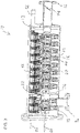
- FIGS. 1-6B illustrate various features of a filter, generally designated 10, constructed and operative according to an embodiment of the present invention, for filtering a flow of liquid.
- filter 10 is implemented as a pressure vessel 12 having an inlet 14 and an outlet 16.
- a filter assembly having a plurality of filter configurations 18 coaxially arrayed along a central flow path 20 in fluid communication with outlet 16.
- Each filter configuration has at least one filter screen 22 overlying one or more filtrate channels 24 which are in fluid connection with central flow path 20 such that liquid within pressure vessel 12 around the filter configurations 18 passes through filter screen 22 and along filtrate channels 24 to central flow path 20 .
- filter configurations 18 are double-sided disks having a filter screen 22 on each face of a spacer which defines internal filtrate channels 24.
- the filter assembly further includes a partition assembly including a partition 26 deployed so as to subdivide pressure vessel 12 into a first filter chamber 28 and a second filter chamber 30, each of which includes at least one of filter assemblies 18.
- the partition assembly also includes a flow diverter 32 deployed within, and interrupting, central flow path 20, so as to divert a flow of filtered liquid passing along central flow path 20 from first filter chamber 28 so as to flow outwards to undergo a second filtering in second filter chamber 30 .
- the effect of the partition assembly is to subdivide the volume of pressure vessel 12 into a two-stage filter configuration.
- Liquid delivered via inlet 14 first enters first filter chamber 28 where it passes through the filter screens of filter assemblies 18 within the first filter chamber and starts to flow along the central flow path 20 towards the second filter chamber.
- flow diverter 32 On reaching flow diverter 32, the liquid is released outwards into the main volume of second filter chamber 30 where it undergoes a second stage filtration at the filter screens of the remaining filter assemblies 18 and flows inwards to the second part of central flow path 20 where it flows to outlet 16.
- the filter preferably employs relatively coarse filter screens 22 with a first opening size in first filter chamber 28 and finer filter screens 22 with a second opening size, smaller than the first opening size, in second filter chamber 30, thereby achieving two-stage filtration within the overall form factor of a single pressure vessel 12.
- partition 26 is typically a flat plate of material shaped to fit the internal dimensions and shape of pressure vessel 12, and typically a round plate for fitting within a cylindrical pressure vessel. Scaling around the outer periphery of partition 26 may advantageously be provided by an elastomer seal 34 which bears an internal surface of the cylindrical wall.
- the rigid plate of partition 26 is formed somewhat undersize for the internal dimensions of the pressure vessel, and elastomer seal 34 is formed as a blade-type seal projecting outwards from the rigid plate. It will be noted that, under normal operating conditions, there is minimal pressure differential across the partition between first and second filter chambers, such that an elastomeric seal of the sort described is typically sufficient to prevent flow from bypassing the first stage of filtration.
- any leakage around the partition would not lead to contamination of the filter output, since it will anyway be subject to the finer second stage of filtering, so the seal does not need to be hermetic.
- the use of a blade-type seal with limited ability to withstand pressure differential between the chambers, is useful as a pressure release feature.
- any localized pressure build up in the first filter chamber is released by deflecting the elastomeric seal, acting as a pressure release valve, thereby avoiding risk of damage to the components of the filter. Filtering quality is maintained by the finer second stage filtering which continues as normal.
- Partition 26 has a near-central aperture within which accommodates flow deflector 32 incorporated into central flow path 20 .
- a collar 36 located within the aperture helps to maintain alignment of partition 26 perpendicular to the central flow path, and allows rotation of flow deflector 32 within the collar 36.
- a second aperture is provided with a tube segment 38 mounted in a bearing arrangement 40 which interconnects with adjacent tube segments to form a backflush axle and drain tube.
- the rigid part of partition 26 may be formed from two or more parts, typically subdivided along a line which passes through the aforementioned apertures.
- the parts are rigidly interconnected, for example, by bolting together of complementary flanges 42 on each side of the partition, as shown.
- Flow diverter 32 is typically a section of tube which has a closed end 44 and lateral openings 46.
- Flow diverter 32 preferably also feature through-bores 48 for accommodating assembly bolts which pass through, and clamp together, the entire filter assembly.
- filter configurations 18 are preferably double-sided disks having a filter screen 22 on each face of a spacer which defines internal filtrate channels 24. Details of various implementations of such filter disks may be found in the aforementioned PCT Patent Publication No. WO2016/030903 , although the invention is not limited to those specific implementations. Most preferably, filter configurations are assembled modularly, such as on the aforementioned set of assembly bolts, in any desired number, and can be arranged in different sequences with the partition assembly. In the configuration illustrated, the device is shown with two filter configurations in the first filter chamber prior to the partition assembly, followed by a sequence of 8 filter configurations in the second filter chamber.
- the components can be assembled in a different sequence, placing the partition assembly after three, or four, filter configurations (with suitable substitution of the filter screens for screens of the required grade).
- the number of filter configurations in the first filter chamber may be reduced, or the partition assembly may be omitted altogether to assemble a larger-area single-stage filter configuration, all according to the requirements of the specific application.
- This modularity provides flexibility to address the needs of each particular application, tailoring the filter solution to the properties of the available water supply and the filter output requirements.
- Filter 10 preferably includes an automated cleaning arrangement deployed to remove accumulated solids from filter screens 22 of the filter configurations 18 in both first filter chamber 28 and second filter chamber 30 during operation of the filter.
- the automated cleaning arrangement is implemented as a backwash assembly for cleaning filter screens 22.
- the backwash assembly preferably includes a plurality of backwash nozzles 50.
- the backwash assembly preferably provides for a scanning motion of backwash nozzles 50 over the surface of filter screens 22. This can be achieved with various different forms of relative motion, as is known in the art.
- backwash nozzles 50 are mounted on backwash arms 52 which connect to a hollow backwash axle 54.
- Axle 54 serves additionally as a conduit connecting the backwash assembly to a drain connection 56.
- a drive connection 58 projects from pressure vessel 12 and is linked to axle 54 so as to allow driving motion of the axle in angular reciprocation. This is preferably combined with a rotary motion of the filter assembly driven via a drive connection 60 aligned with central flow path 20.
- By driving drive connection 60 in continuous rotation and drive connection 58 in a reciprocating angular motion backwash nozzles 50 are made to follow a spiral scanning path across the surface of filter screens 22, thereby progressively sweeping across the entire active surface of the filter screens.
- the gaps between adjacent filter disk assemblies accommodate two backwash nozzles, one for cleaning the left surface of the right-side assembly and the other for cleaning the right surface of the left-side assembly.
- the backwash assembly thus far described is essentially similar to that of the aforementioned PCT Patent Publication No. WO2016/030903 , and further details of at least one non-limiting preferred implementation may be found therein.
- the aforementioned backwash assembly is preferably adapted to accommodate the subdivision of the pressure vessel into first and second filter chambers, while maintaining a common backwash axle 54 and drive system for the backwash arrangement in both filter chambers.
- tube segment 38 interlocks with the remaining modular segments of hollow axle 54 to provide a unified shaft passing through, and rotatable relative to, partition 26.
- flow diverter 32 united via rods passing through through-bores 48 with the other modular segments of central flow path 20 passing through the filter assemblies 18, forms a unitary central column of the filter assembly which passes through, and is rotatable relative to, partition 26.
- this relates to a system and corresponding method for operating a filter with an automated cleaning arrangement, such as a backwash cleaning arrangement, in which an adjustable valve 62 associated with outlet 16 is adjustable to vary a flow impedance for liquid flowing via the outlet.
- a controller 64 is deployed to control adjustable valve 62 responsively to a pressure difference between liquid pressure at the inlet and at the outlet such that, when the pressure difference exceeds a predetermined value, the controller controls the adjustable valve to constrict a rate of liquid flow via the outlet until operation of the automated cleaning arrangement stabilizes the pressure difference.
- Filter systems are preferably implemented such that, under normal operating conditions, there is a small pressure differential across the filter screen.
- the backwash cleaning system may run continuously, or intermittently, on a timer and/or when triggered by a slightly increased pressure difference indicative of accumulation of solids on the filter screens.
- there are large variations in the quantities of suspended solids in the supplied fluid which may vary by orders of magnitude, peaking at certain times.
- One such example is a water supply drawn from sources which at times include run-off rain water which may suddenly introduce unusual quantities of soil and other particles into a water source.
- the rate of accumulation of solids on the fiber screens may be such that the time taken between passes of each backwash nozzle over a certain region of filter screen exceeds the time taken for the fitter screen to become clogged. This results in a progressive build-up of solids on the filter screens, progressively choking the filtering process. If this accumulation continues unabated, the pressure downstream of the filter screen drops drastically, which in turn reduces the efficiency of the backwash process which requires a significant pressure differential between the downstream side of the screen and the drain in order to clean the screen. These effects would normally compound each other, leading rapidly to complete blockage of the filter. Once blocked, the backwash is ineffective, and the filter cannot be returned to operation without major servicing.
- This aspect of the present invention addresses this problem by responding to increased pressure difference across the filter so as to throttle liquid flow through the filter.
- the reduced rate of flow inherently reduces the rate of build-up of solids on the filter screen until a balance is reached at which the backwash system is keep up with the rate of accumulation of solids and maintain proper operation of the filter.
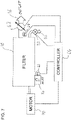
- FIG. 7 illustrates schematically a first system for implementing the above aspect of the present invention.
- Filter 10 is provided with sensing connections to the pressure vessel which allow sensing of a pressure differential between inlet 14 and outlet 16.
- these sensing connections are implemented as pressure sensors 66 and 68 which are deployed to generate respective signals indicative of the inlet and outlet pressures P1 and P2, respectively, which are supplied to controller 64.
- the controller is preferably implemented as an electronic controller, which may be implemented using analogue or digital electronics, and may be a dedicated device or a suitably-programmed device based on one or more general-purpose microprocessors.
- Controller 64 preferably includes outputs for selectively actuation a motor drive system 70 which is linked to drive the required motions of drive connections 58 and 60 (mechanical details omitted for simplicity) and an electrically-actuated open-closed valve 72 on drain 56. This allows controller 64 to control starting and stopping of the backwash cleaning cycle. Additionally, controller 64 has an output associated with an actuator of adjustable valve 62.
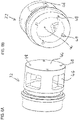
- adjustable valve 62 as shown in detail in FIG. 9 includes an electrically-controlled actuator 74 deployed to displace a linkage 76 which rotates a shutter element 78, here implemented as a centrally-pivoting disc. Pivoting of the shutter element between a state parallel to the flow and a state angled to the flow direction causes adjustment of the flow impedance through outlet 16, and thus of flow rates through the filter. It should be noted that adjustable valve essentially performs a throttling (flow reduction) function, and is not necessarily designed to achieve complete occlusion of the flow path in its maximum-throttling state.
- FIG. 8 illustrates a non-limiting exemplary flow process for operation of the system of FIG. 7 .
- the process monitors at 82 whether the pressure differential ("PD") between P1 and P2 exceeds a first threshold value, for example, 0.5 bar. If not, no action is taken and operation of the filter continues without intervention of the control system.
- a first threshold value for example, 0.5 bar. If not, no action is taken and operation of the filter continues without intervention of the control system.
- the backwash system is actuated (i.e., by actuating motor drive system 70 and opening drain valve 72. While the backwash system is operating, the PD is monitored for various different conditions. If PD falls back below a base value, typically somewhat lower than the first threshold value (e.g., 0.3 bar), the backwash is stopped and the filter returns to passive operation.
- a base value typically somewhat lower than the first threshold value (e.g., 0.3 bar)
- step 90 controller 64 controls adjustable valve 62 so as to reduce the flow rate through the filter until PD is controlled, keeping the PD within some target range.
- closed-loop adjustment of the flow rate is performed to stabilize the PD at or near a target value of, for example, 0.5 bar.
- sensing connections to the inlet and outlet pressure are pressure sensors generating electrical signals
- hydraulic sensing connections may also be used, and in some cases, the functions of the controller may be performed using a hydraulic controller/actuator integrated with adjustable valve 62.
- One such alternative implementation is illustrated schematically in FIG. 10 .
- FIG. 10 shows an outlet pipe 94 defining a flow path from central flow path 20 via a valve seat 96 to outlet 16.
- a closure element 98 is movable relative to valve seat 96 to adjust the flow impedance of the valve.
- Displacement of the closure element is controlled by a hydraulic actuator, which may be a piston-based actuator with a piston 100 as shown or a diaphragm-based actuator.
- the actuator has a first chamber 102 on one side of the piston acting to close closure element 98 in fluid connection with a source of inlet pressure, and a second chamber 104 on the opposite side of the piston acting to open closure element 98 in fluid connection with a source of outlet pressure.
- a spring 106 provides additional bias towards the open position.
- the present invention can equally be applied in other contexts in which a backwash cleaning system passes over the surface of a filter screen.
- Other suitable applications include cases in which the filter screen is cylindrical, and where a suction nozzle traces a helical path across a surface of the filter screen.
- the present invention may be applied to a range of other situations in which an automated cleaning arrangement operates to remove accumulated solids from the filter screens, including but not limited to arrangements with brushes or other mechanical arrangements for removing "cake" from filter screens, and sequential backwash arrangements in which reverse liquid pressure is applied sequentially to successive filter elements from a group of filter elements normally operating in parallel.
Landscapes
- Chemical & Material Sciences (AREA)
- Chemical Kinetics & Catalysis (AREA)
- Filtration Of Liquid (AREA)
- Centrifugal Separators (AREA)
- Water Treatment By Sorption (AREA)
- Fluid-Pressure Circuits (AREA)
Claims (9)
- Filter (10) zum Filtern eines Flüssigkeitsstroms, wobei der Filter Folgendes umfasst:(a) einen Druckbehälter (12) mit einem Einlass (14), einem Auslass (16) und einer zylindrischen Wand;(b) eine Trennwand (26), die innerhalb des Druckbehälters angeordnet ist, um den Druckbehälter in eine erste Filterkammer (28) und eine zweite Filterkammer (30) zu unterteilen, wobei die Trennwand (26) mit einer Elastomerdichtung zum Abdichten gegen eine Innenfläche der zylindrischen Wand ausgebildet ist;(c) eine erste Filterkonfiguration (18), die innerhalb der ersten Filterkammer (28) eingesetzt ist, wobei die erste Filterkonfiguration ein Filtersieb (22) mit einer ersten Öffnungsgröße umfasst;(d) eine zweite Filterkonfiguration (18), die innerhalb der zweiten Filterkammer (30) eingesetzt ist, wobei die zweite Filterkonfiguration ein Filtersieb (22) mit einer zweiten Öffnungsgröße aufweist, die kleiner als die erste Öffnungsgröße ist, wobei Flüssigkeit, die von dem Einlass zu dem Auslass fließt, sequentiell durch die erste Filterkonfiguration und durch die zweite Filterkonfiguration strömt; und(e) eine automatisierte Reinigungsanordnung, die eingesetzt wird, um angesammelte Feststoffe von den Filtersieben (22) sowohl der ersten Filterkonfiguration als auch der zweiten Filterkonfiguration während des Betriebs des Filters zu entfernen, wobei die automatisierte Reinigungsanordnung eine Rückspülanordnung umfasst, die mindestens eine Rückspüldüse (50) enthält, die zum Reinigen des Filtersiebs (22) von jeder der ersten und zweiten Filterkonfiguration eingesetzt wird,wobei jede der ersten und zweiten Filterkonfigurationen (18) eine Filterscheibe ist, die einen Abstandshalter mit ersten und zweiten nach außen weisenden Filtersiebträgerkonfigurationen umfasst, und einen Auslass zum Strömen von gefilterter Flüssigkeit nach innen zu einem zentralen Strömungsweg aufweist, wobei die ersten und zweiten Filtersiebträgerkonfigurationen des Abstandshalters erste und zweite Filtersiebe tragen, die entsprechende erste und zweite Oberflächen der Filterscheibe bilden,und dadurch, dass der Filter ferner einen Strömungsumlenker (32) umfasst, der in dem zentralen Strömungsweg eingesetzt ist, um einen Strom gefilterter Flüssigkeit abzulenken, der entlang des zentralen Strömungswegs von der ersten Filterkonfiguration strömt, um von dem zentralen Strömungsweg nach außen zu fließen, um in der zweiten Filterkammer einer zweiten Filterung unterzogen zu werden.
- Filter (10) nach Anspruch 1, wobei die Vielzahl von Filterkonfigurationen (18) mindestens eine dritte Filterkonfiguration umfassen, und wobei die Filterkonfigurationen (18) und die Trennwand (26) zum abwechselnden Zusammenbau in einer ersten Konfiguration konfiguriert sind, in der die dritte Filterkonfiguration auf einer ersten Seite der Trennwand eingesetzt ist, um innerhalb der ersten Filterkammer zu sein, und eine zweite Konfiguration, in der die dritte Filterkonfiguration auf einer zweiten Seite der Trennwand eingesetzt ist, um innerhalb der zweiten Filterkammer zu sein,
wodurch eine Anzahl der Filterkonfigurationen in jeder der ersten und zweiten Filterkammern variiert wird. - Filter (10) nach Anspruch 1, wobei die Vielzahl von Rückspüldüsen montiert sind, um sich zusammen mit einer Rückspülanordnungsachse (54) zu bewegen, wobei die Rückspülanordnungsachse durch die Trennwand (26) verläuft, um sich sowohl innerhalb der ersten als auch der zweiten Filterkammer (28, 30) zu erstrecken.
- Filter (10) nach Anspruch 1, wobei die automatisierte Reinigungsanordnung Folgendes umfasst:(i) mindestens zwei Rückspülleitungen (52), wobei jede der Rückspülleitungen in einer der Saugdüsen (50) endet, die gegenüber dem Filtersieb der ersten Filterkonfiguration oder der zweiten Filterkonfiguration angeordnet ist, wobei jede der Rückspülleitungen in Fluidverbindung mit einem Rückspülablauf (56) steht; und(ii) einen Antriebsmechanismus zum Verschieben der Saugdüse und/oder des Filtersiebs der ersten Filterkonfiguration und der zweiten Filterkonfiguration, um eine relative Abtastbewegung jeder der Saugdüsen über einen Bereich des Filtersiebs der ersten Filterkonfiguration und der zweiten Filterkonfiguration zu erzeugen,wobei der Filter ferner Folgendes umfasst:(a) ein einstellbares Ventil (62), das dem Auslass zugeordnet und einstellbar ist, um eine Strömungsimpedanz für Flüssigkeit, die über den Auslass (16) fließt, zu verändern; und(b) eine Steuerung (64), die eingesetzt wird, um das einstellbare Ventil zu steuern, wobei die Steuerung Erfassungsverbindungen zu dem Druckbehälter (12) aufweist und so konfiguriert ist, dass sie auf eine Druckdifferenz zwischen dem Flüssigkeitsdruck an dem Einlass (14) und an dem Auslass (16) anspricht, so dass, wenn die Druckdifferenz einen vorbestimmten Wert übersteigt, die Steuerung das einstellbare Ventil steuert, um eine Flüssigkeitsströmungsrate über den Auslass einzuschränken, bis der Betrieb der automatisierten Reinigungsanordnung die Druckdifferenz stabilisiert.
- Filter (10) nach Anspruch 4, wobei die Filtersiebe (22) der ersten Filterkonfiguration und der zweiten Filterkonfiguration flach sind, und wobei jede der Saugdüsen (50) einen spiralförmigen Weg über eine Oberfläche des Filtersiebs der ersten Filterkonfiguration oder der zweiten Filterkonfiguration verfolgt.
- Filter (10) nach Anspruch 4, wobei die Filterscheiben der ersten Filterkonfiguration und der zweiten Filterkonfiguration koaxial entlang eines zentralen Strömungswegs angeordnet sind, wobei der Antriebsmechanismus einen Drehantrieb zum Antreiben einer Drehung der Filteranordnung um eine Achse der Filteranordnung umfasst.
- Filter (10) nach Anspruch 6, wobei sich die Rückspülleitung entlang eines Rückspülarms (52) erstreckt, wobei der Antriebsmechanismus den Rückspülarm in einer bogenförmigen Hin- und Herbewegung bewegt, so dass sich die Saugdüse (50) auf einem spiralförmigen Weg über eine Oberfläche der Filtersiebe (22) bewegt.
- Filter ( 10 ) nach Anspruch 4, wobei die Steuerung ( 64 ) eine elektronische Steuerung ist, die ein Verarbeitungssystem und einen Aktuator umfasst, der von dem Verarbeitungssystem betrieben wird, um das einstellbare Ventil einzustellen, wobei die Erfassungsverbindungen als elektrische Verbindungen zu Drucksensoren (66, 68) implementiert sind, die zum Erfassen eines Drucks in dem Einlass (14) und eines Drucks in dem Auslass (16) eingesetzt sind.
- Filter (10) nach Anspruch 4, wobei die Steuerung (64) eine hydraulische Steuerung ist, die mindestens einen hydraulischen Aktuator umfasst, der eingesetzt wird, um das einstellbare Ventil einzustellen, wobei die Messverbindungen als hydraulische Verbindungen zu dem Einlass (14) und dem Auslass (16) implementiert sind.
Applications Claiming Priority (2)
| Application Number | Priority Date | Filing Date | Title |
|---|---|---|---|
| IL251485A IL251485A0 (en) | 2017-03-30 | 2017-03-30 | water filter |
| PCT/IL2018/050171 WO2018178965A1 (en) | 2017-03-30 | 2018-02-14 | Water filter |
Publications (3)
| Publication Number | Publication Date |
|---|---|
| EP3600599A1 EP3600599A1 (de) | 2020-02-05 |
| EP3600599A4 EP3600599A4 (de) | 2020-05-20 |
| EP3600599B1 true EP3600599B1 (de) | 2022-04-27 |
Family
ID=62242315
Family Applications (1)
| Application Number | Title | Priority Date | Filing Date |
|---|---|---|---|
| EP18774466.9A Active EP3600599B1 (de) | 2017-03-30 | 2018-02-14 | Wasserfilter |
Country Status (7)
| Country | Link |
|---|---|
| US (1) | US10994231B2 (de) |
| EP (1) | EP3600599B1 (de) |
| KR (1) | KR102530722B1 (de) |
| CN (1) | CN110062646B (de) |
| ES (1) | ES2923911T3 (de) |
| IL (1) | IL251485A0 (de) |
| WO (1) | WO2018178965A1 (de) |
Families Citing this family (10)
| Publication number | Priority date | Publication date | Assignee | Title |
|---|---|---|---|---|
| WO2019106673A1 (en) | 2017-11-29 | 2019-06-06 | Maagan Filtration Aca Ltd. | Filtration system |
| US11000791B2 (en) * | 2019-03-06 | 2021-05-11 | Veolia Water Solutions & Technologies Support | Rotary disc filter having backwash guides |
| CN112195635B (zh) * | 2020-10-22 | 2022-07-12 | 仁净(江苏)集成系统科技有限公司 | 一种环保设备除尘机 |
| CN114917666A (zh) * | 2021-01-31 | 2022-08-19 | 湖南迪易清环保科技有限公司 | 一种轮型滤芯及水处理装置 |
| CN113086085B (zh) * | 2021-04-22 | 2022-07-05 | 中船黄埔文冲船舶有限公司 | 一种海水滤器及使用方法 |
| CN113509782B (zh) * | 2021-04-28 | 2022-12-30 | 中船黄埔文冲船舶有限公司 | 一种船用多级海水滤器及使用方法 |
| CN113509783B (zh) * | 2021-04-28 | 2022-12-30 | 中船黄埔文冲船舶有限公司 | 一种多级海水滤芯、海水滤器及使用方法 |
| CN114307328B (zh) * | 2021-12-14 | 2022-12-27 | 泰州科聚新材料技术研究院有限公司 | 一种高分子废水过滤净化残渣干燥装置 |
| CN115581959B (zh) * | 2022-09-20 | 2025-06-13 | 上海市安装工程集团有限公司 | 过滤器及空调水系统冲洗过滤装置 |
| CN116966661A (zh) * | 2023-09-20 | 2023-10-31 | 山东锆石智能设备有限公司 | 一种环保型水利工程用过滤装置 |
Citations (1)
| Publication number | Priority date | Publication date | Assignee | Title |
|---|---|---|---|---|
| US20110297604A1 (en) * | 2008-11-04 | 2011-12-08 | Bryan Deborah M | Fluid interconnect |
Family Cites Families (17)
| Publication number | Priority date | Publication date | Assignee | Title |
|---|---|---|---|---|
| US2712387A (en) * | 1950-10-19 | 1955-07-05 | Frank W Young | Rotary filter with pulsating blowback means |
| GB1184066A (en) * | 1966-06-07 | 1970-03-11 | Euroflow Systems Ltd | Improvements in or relating to Filter Apparatus |
| US3497452A (en) * | 1968-09-09 | 1970-02-24 | Kostas Savas Arvanitakis | Method and apparatus for clarifying a liquid |
| FR2554735B1 (fr) * | 1983-11-16 | 1986-03-28 | Moatti Georges | Filtre a deux empilements distincts de filtration |
| JPS6190716A (ja) * | 1984-10-11 | 1986-05-08 | Kaname Miura | 動的ろ過装置 |
| AU3729495A (en) * | 1994-09-01 | 1996-03-22 | Pyrox, Inc. | High capacity ultrafiltration apparatus |
| US5914048A (en) * | 1997-11-13 | 1999-06-22 | Beloit Technologies, Inc. | Adjustable control valve system for rotating disc filter and method of operating the system |
| US6294098B1 (en) * | 2000-05-23 | 2001-09-25 | Aqua-Aerobics System, Inc. | High efficiency backwash shoe |
| US20030146171A1 (en) * | 2002-02-04 | 2003-08-07 | Karl-Heinz Herrmann | Liquid and solids separation apparatus and method with continuous cleaning using defferential pressure control |
| US8496821B2 (en) * | 2007-12-28 | 2013-07-30 | Caterpillar Inc. | Systems and methods for filtering fuel |
| EP2605848B1 (de) * | 2010-08-20 | 2019-01-23 | Trojan Technologies | Fluidfiltervorrichtung |
| DE102011100518A1 (de) * | 2011-05-05 | 2012-11-08 | Hydac Process Technology Gmbh | Filtervorrichtung |
| GB2490543B (en) * | 2011-05-06 | 2013-06-12 | Moss Hydro As | Filter arrangement |
| EA030903B1 (ru) * | 2013-04-17 | 2018-10-31 | Оутотек (Финлэнд) Ой | Дисковый фильтр и способ управления дисковым фильтром |
| DE102014103831A1 (de) * | 2014-03-20 | 2015-09-24 | Huber Se | Filtereinrichtung zur Filtration von Abwasser |
| KR101985583B1 (ko) * | 2014-08-31 | 2019-06-03 | 필터 아트 엘티디 | 적층식 필터 디스크 구조를 채용한 필터 |
| WO2018031884A1 (en) * | 2016-08-12 | 2018-02-15 | Evoqua Water Technologies Llc | Disc filter pre-screen dual media disc filter |
-
2017
- 2017-03-30 IL IL251485A patent/IL251485A0/en active IP Right Grant
-
2018
- 2018-02-14 US US16/473,644 patent/US10994231B2/en active Active
- 2018-02-14 ES ES18774466T patent/ES2923911T3/es active Active
- 2018-02-14 KR KR1020197016966A patent/KR102530722B1/ko active Active
- 2018-02-14 WO PCT/IL2018/050171 patent/WO2018178965A1/en not_active Ceased
- 2018-02-14 CN CN201880004991.7A patent/CN110062646B/zh active Active
- 2018-02-14 EP EP18774466.9A patent/EP3600599B1/de active Active
Patent Citations (1)
| Publication number | Priority date | Publication date | Assignee | Title |
|---|---|---|---|---|
| US20110297604A1 (en) * | 2008-11-04 | 2011-12-08 | Bryan Deborah M | Fluid interconnect |
Also Published As
| Publication number | Publication date |
|---|---|
| EP3600599A4 (de) | 2020-05-20 |
| WO2018178965A9 (en) | 2019-03-07 |
| EP3600599A1 (de) | 2020-02-05 |
| ES2923911T3 (es) | 2022-10-03 |
| CN110062646A (zh) | 2019-07-26 |
| CN110062646B (zh) | 2022-10-25 |
| US10994231B2 (en) | 2021-05-04 |
| KR102530722B1 (ko) | 2023-05-09 |
| US20200009484A1 (en) | 2020-01-09 |
| IL251485A0 (en) | 2017-05-29 |
| WO2018178965A1 (en) | 2018-10-04 |
| KR20190129824A (ko) | 2019-11-20 |
Similar Documents
| Publication | Publication Date | Title |
|---|---|---|
| EP3600599B1 (de) | Wasserfilter | |
| US5152891A (en) | Self-cleaning strainer | |
| KR101299806B1 (ko) | 유체 필터 | |
| US9669335B2 (en) | Filter apparatus | |
| US9744486B2 (en) | Filter device | |
| EP2903713B1 (de) | Servogesteuertes rückspülfiltersystem | |
| US5516426A (en) | Self-cleaning filter system | |
| US3389797A (en) | Filtering system having dual cleaning means | |
| KR101961088B1 (ko) | 여과 장치 | |
| GB2035115A (en) | Backwashable fluid filter | |
| CN110402164A (zh) | 过滤装置 | |
| CN111565813A (zh) | 过滤器设备 | |
| US7081207B2 (en) | Method for cleaning a filter element in a filtering chamber and filter carrying out the method | |
| JP2014094346A (ja) | 濾過装置 | |
| US20150090655A1 (en) | Filtration assembly with backwashing for pressurized fluid system | |
| EP4234063A1 (de) | Filteranordnung, fluidhandhabungssystem und verfahren | |
| WO2006051336A2 (en) | A fluid filtration system and method of filtering fluid | |
| WO2024263124A1 (en) | A self-cleaning filter assembly | |
| WO2014125056A1 (en) | Multi-basket filter | |
| HU205276B (en) | Filter | |
| IL161727A (en) | Filter and filter cleaning apparatus and related methods |
Legal Events
| Date | Code | Title | Description |
|---|---|---|---|
| STAA | Information on the status of an ep patent application or granted ep patent |
Free format text: STATUS: THE INTERNATIONAL PUBLICATION HAS BEEN MADE |
|
| PUAI | Public reference made under article 153(3) epc to a published international application that has entered the european phase |
Free format text: ORIGINAL CODE: 0009012 |
|
| STAA | Information on the status of an ep patent application or granted ep patent |
Free format text: STATUS: REQUEST FOR EXAMINATION WAS MADE |
|
| 17P | Request for examination filed |
Effective date: 20190626 |
|
| AK | Designated contracting states |
Kind code of ref document: A1 Designated state(s): AL AT BE BG CH CY CZ DE DK EE ES FI FR GB GR HR HU IE IS IT LI LT LU LV MC MK MT NL NO PL PT RO RS SE SI SK SM TR |
|
| AX | Request for extension of the european patent |
Extension state: BA ME |
|
| RIC1 | Information provided on ipc code assigned before grant |
Ipc: B01D 29/68 20060101ALI20200207BHEP Ipc: B01D 29/58 20060101ALI20200207BHEP Ipc: B01D 29/54 20060101ALI20200207BHEP Ipc: B01D 33/46 20060101ALI20200207BHEP Ipc: B01D 33/44 20060101ALI20200207BHEP Ipc: B01D 33/39 20060101ALI20200207BHEP Ipc: B01D 33/23 20060101ALI20200207BHEP Ipc: B01D 33/21 20060101AFI20200207BHEP Ipc: B01D 29/41 20060101ALI20200207BHEP Ipc: B01D 33/48 20060101ALI20200207BHEP Ipc: B01D 29/62 20060101ALI20200207BHEP |
|
| A4 | Supplementary search report drawn up and despatched |
Effective date: 20200422 |
|
| RIC1 | Information provided on ipc code assigned before grant |
Ipc: B01D 29/68 20060101ALI20200416BHEP Ipc: B01D 29/41 20060101ALI20200416BHEP Ipc: B01D 33/23 20060101ALI20200416BHEP Ipc: B01D 33/44 20060101ALI20200416BHEP Ipc: B01D 33/39 20060101ALI20200416BHEP Ipc: B01D 33/21 20060101AFI20200416BHEP Ipc: B01D 29/58 20060101ALI20200416BHEP Ipc: B01D 29/62 20060101ALI20200416BHEP Ipc: B01D 33/46 20060101ALI20200416BHEP Ipc: B01D 33/48 20060101ALI20200416BHEP Ipc: B01D 29/54 20060101ALI20200416BHEP |
|
| DAV | Request for validation of the european patent (deleted) | ||
| DAX | Request for extension of the european patent (deleted) | ||
| STAA | Information on the status of an ep patent application or granted ep patent |
Free format text: STATUS: EXAMINATION IS IN PROGRESS |
|
| 17Q | First examination report despatched |
Effective date: 20210223 |
|
| GRAP | Despatch of communication of intention to grant a patent |
Free format text: ORIGINAL CODE: EPIDOSNIGR1 |
|
| STAA | Information on the status of an ep patent application or granted ep patent |
Free format text: STATUS: GRANT OF PATENT IS INTENDED |
|
| RIN1 | Information on inventor provided before grant (corrected) |
Inventor name: ULIEL, ERAN |
|
| INTG | Intention to grant announced |
Effective date: 20211111 |
|
| GRAS | Grant fee paid |
Free format text: ORIGINAL CODE: EPIDOSNIGR3 |
|
| GRAA | (expected) grant |
Free format text: ORIGINAL CODE: 0009210 |
|
| STAA | Information on the status of an ep patent application or granted ep patent |
Free format text: STATUS: THE PATENT HAS BEEN GRANTED |
|
| AK | Designated contracting states |
Kind code of ref document: B1 Designated state(s): AL AT BE BG CH CY CZ DE DK EE ES FI FR GB GR HR HU IE IS IT LI LT LU LV MC MK MT NL NO PL PT RO RS SE SI SK SM TR |
|
| REG | Reference to a national code |
Ref country code: GB Ref legal event code: FG4D |
|
| REG | Reference to a national code |
Ref country code: CH Ref legal event code: EP |
|
| REG | Reference to a national code |
Ref country code: AT Ref legal event code: REF Ref document number: 1486475 Country of ref document: AT Kind code of ref document: T Effective date: 20220515 |
|
| REG | Reference to a national code |
Ref country code: DE Ref legal event code: R096 Ref document number: 602018034578 Country of ref document: DE |
|
| REG | Reference to a national code |
Ref country code: IE Ref legal event code: FG4D |
|
| REG | Reference to a national code |
Ref country code: NL Ref legal event code: FP |
|
| REG | Reference to a national code |
Ref country code: LT Ref legal event code: MG9D |
|
| REG | Reference to a national code |
Ref country code: AT Ref legal event code: MK05 Ref document number: 1486475 Country of ref document: AT Kind code of ref document: T Effective date: 20220427 |
|
| REG | Reference to a national code |
Ref country code: ES Ref legal event code: FG2A Ref document number: 2923911 Country of ref document: ES Kind code of ref document: T3 Effective date: 20221003 |
|
| PG25 | Lapsed in a contracting state [announced via postgrant information from national office to epo] |
Ref country code: SE Free format text: LAPSE BECAUSE OF FAILURE TO SUBMIT A TRANSLATION OF THE DESCRIPTION OR TO PAY THE FEE WITHIN THE PRESCRIBED TIME-LIMIT Effective date: 20220427 Ref country code: PT Free format text: LAPSE BECAUSE OF FAILURE TO SUBMIT A TRANSLATION OF THE DESCRIPTION OR TO PAY THE FEE WITHIN THE PRESCRIBED TIME-LIMIT Effective date: 20220829 Ref country code: NO Free format text: LAPSE BECAUSE OF FAILURE TO SUBMIT A TRANSLATION OF THE DESCRIPTION OR TO PAY THE FEE WITHIN THE PRESCRIBED TIME-LIMIT Effective date: 20220727 Ref country code: LT Free format text: LAPSE BECAUSE OF FAILURE TO SUBMIT A TRANSLATION OF THE DESCRIPTION OR TO PAY THE FEE WITHIN THE PRESCRIBED TIME-LIMIT Effective date: 20220427 Ref country code: HR Free format text: LAPSE BECAUSE OF FAILURE TO SUBMIT A TRANSLATION OF THE DESCRIPTION OR TO PAY THE FEE WITHIN THE PRESCRIBED TIME-LIMIT Effective date: 20220427 Ref country code: GR Free format text: LAPSE BECAUSE OF FAILURE TO SUBMIT A TRANSLATION OF THE DESCRIPTION OR TO PAY THE FEE WITHIN THE PRESCRIBED TIME-LIMIT Effective date: 20220728 Ref country code: FI Free format text: LAPSE BECAUSE OF FAILURE TO SUBMIT A TRANSLATION OF THE DESCRIPTION OR TO PAY THE FEE WITHIN THE PRESCRIBED TIME-LIMIT Effective date: 20220427 Ref country code: BG Free format text: LAPSE BECAUSE OF FAILURE TO SUBMIT A TRANSLATION OF THE DESCRIPTION OR TO PAY THE FEE WITHIN THE PRESCRIBED TIME-LIMIT Effective date: 20220727 Ref country code: AT Free format text: LAPSE BECAUSE OF FAILURE TO SUBMIT A TRANSLATION OF THE DESCRIPTION OR TO PAY THE FEE WITHIN THE PRESCRIBED TIME-LIMIT Effective date: 20220427 |
|
| PG25 | Lapsed in a contracting state [announced via postgrant information from national office to epo] |
Ref country code: RS Free format text: LAPSE BECAUSE OF FAILURE TO SUBMIT A TRANSLATION OF THE DESCRIPTION OR TO PAY THE FEE WITHIN THE PRESCRIBED TIME-LIMIT Effective date: 20220427 Ref country code: PL Free format text: LAPSE BECAUSE OF FAILURE TO SUBMIT A TRANSLATION OF THE DESCRIPTION OR TO PAY THE FEE WITHIN THE PRESCRIBED TIME-LIMIT Effective date: 20220427 Ref country code: LV Free format text: LAPSE BECAUSE OF FAILURE TO SUBMIT A TRANSLATION OF THE DESCRIPTION OR TO PAY THE FEE WITHIN THE PRESCRIBED TIME-LIMIT Effective date: 20220427 Ref country code: IS Free format text: LAPSE BECAUSE OF FAILURE TO SUBMIT A TRANSLATION OF THE DESCRIPTION OR TO PAY THE FEE WITHIN THE PRESCRIBED TIME-LIMIT Effective date: 20220827 |
|
| REG | Reference to a national code |
Ref country code: DE Ref legal event code: R097 Ref document number: 602018034578 Country of ref document: DE |
|
| PG25 | Lapsed in a contracting state [announced via postgrant information from national office to epo] |
Ref country code: SM Free format text: LAPSE BECAUSE OF FAILURE TO SUBMIT A TRANSLATION OF THE DESCRIPTION OR TO PAY THE FEE WITHIN THE PRESCRIBED TIME-LIMIT Effective date: 20220427 Ref country code: SK Free format text: LAPSE BECAUSE OF FAILURE TO SUBMIT A TRANSLATION OF THE DESCRIPTION OR TO PAY THE FEE WITHIN THE PRESCRIBED TIME-LIMIT Effective date: 20220427 Ref country code: RO Free format text: LAPSE BECAUSE OF FAILURE TO SUBMIT A TRANSLATION OF THE DESCRIPTION OR TO PAY THE FEE WITHIN THE PRESCRIBED TIME-LIMIT Effective date: 20220427 Ref country code: EE Free format text: LAPSE BECAUSE OF FAILURE TO SUBMIT A TRANSLATION OF THE DESCRIPTION OR TO PAY THE FEE WITHIN THE PRESCRIBED TIME-LIMIT Effective date: 20220427 Ref country code: DK Free format text: LAPSE BECAUSE OF FAILURE TO SUBMIT A TRANSLATION OF THE DESCRIPTION OR TO PAY THE FEE WITHIN THE PRESCRIBED TIME-LIMIT Effective date: 20220427 Ref country code: CZ Free format text: LAPSE BECAUSE OF FAILURE TO SUBMIT A TRANSLATION OF THE DESCRIPTION OR TO PAY THE FEE WITHIN THE PRESCRIBED TIME-LIMIT Effective date: 20220427 |
|
| PLBE | No opposition filed within time limit |
Free format text: ORIGINAL CODE: 0009261 |
|
| STAA | Information on the status of an ep patent application or granted ep patent |
Free format text: STATUS: NO OPPOSITION FILED WITHIN TIME LIMIT |
|
| PG25 | Lapsed in a contracting state [announced via postgrant information from national office to epo] |
Ref country code: AL Free format text: LAPSE BECAUSE OF FAILURE TO SUBMIT A TRANSLATION OF THE DESCRIPTION OR TO PAY THE FEE WITHIN THE PRESCRIBED TIME-LIMIT Effective date: 20220427 |
|
| 26N | No opposition filed |
Effective date: 20230130 |
|
| PG25 | Lapsed in a contracting state [announced via postgrant information from national office to epo] |
Ref country code: SI Free format text: LAPSE BECAUSE OF FAILURE TO SUBMIT A TRANSLATION OF THE DESCRIPTION OR TO PAY THE FEE WITHIN THE PRESCRIBED TIME-LIMIT Effective date: 20220427 |
|
| PG25 | Lapsed in a contracting state [announced via postgrant information from national office to epo] |
Ref country code: MC Free format text: LAPSE BECAUSE OF FAILURE TO SUBMIT A TRANSLATION OF THE DESCRIPTION OR TO PAY THE FEE WITHIN THE PRESCRIBED TIME-LIMIT Effective date: 20220427 |
|
| REG | Reference to a national code |
Ref country code: CH Ref legal event code: PL |
|
| REG | Reference to a national code |
Ref country code: BE Ref legal event code: MM Effective date: 20230228 |
|
| GBPC | Gb: european patent ceased through non-payment of renewal fee |
Effective date: 20230214 |
|
| PG25 | Lapsed in a contracting state [announced via postgrant information from national office to epo] |
Ref country code: LU Free format text: LAPSE BECAUSE OF NON-PAYMENT OF DUE FEES Effective date: 20230214 Ref country code: LI Free format text: LAPSE BECAUSE OF NON-PAYMENT OF DUE FEES Effective date: 20230228 Ref country code: CH Free format text: LAPSE BECAUSE OF NON-PAYMENT OF DUE FEES Effective date: 20230228 |
|
| REG | Reference to a national code |
Ref country code: IE Ref legal event code: MM4A |
|
| PG25 | Lapsed in a contracting state [announced via postgrant information from national office to epo] |
Ref country code: GB Free format text: LAPSE BECAUSE OF NON-PAYMENT OF DUE FEES Effective date: 20230214 |
|
| PG25 | Lapsed in a contracting state [announced via postgrant information from national office to epo] |
Ref country code: IE Free format text: LAPSE BECAUSE OF NON-PAYMENT OF DUE FEES Effective date: 20230214 Ref country code: GB Free format text: LAPSE BECAUSE OF NON-PAYMENT OF DUE FEES Effective date: 20230214 |
|
| PG25 | Lapsed in a contracting state [announced via postgrant information from national office to epo] |
Ref country code: BE Free format text: LAPSE BECAUSE OF NON-PAYMENT OF DUE FEES Effective date: 20230228 |
|
| PG25 | Lapsed in a contracting state [announced via postgrant information from national office to epo] |
Ref country code: BG Free format text: LAPSE BECAUSE OF FAILURE TO SUBMIT A TRANSLATION OF THE DESCRIPTION OR TO PAY THE FEE WITHIN THE PRESCRIBED TIME-LIMIT Effective date: 20220427 |
|
| PG25 | Lapsed in a contracting state [announced via postgrant information from national office to epo] |
Ref country code: BG Free format text: LAPSE BECAUSE OF FAILURE TO SUBMIT A TRANSLATION OF THE DESCRIPTION OR TO PAY THE FEE WITHIN THE PRESCRIBED TIME-LIMIT Effective date: 20220427 |
|
| PG25 | Lapsed in a contracting state [announced via postgrant information from national office to epo] |
Ref country code: CY Free format text: LAPSE BECAUSE OF FAILURE TO SUBMIT A TRANSLATION OF THE DESCRIPTION OR TO PAY THE FEE WITHIN THE PRESCRIBED TIME-LIMIT; INVALID AB INITIO Effective date: 20180214 |
|
| PG25 | Lapsed in a contracting state [announced via postgrant information from national office to epo] |
Ref country code: HU Free format text: LAPSE BECAUSE OF FAILURE TO SUBMIT A TRANSLATION OF THE DESCRIPTION OR TO PAY THE FEE WITHIN THE PRESCRIBED TIME-LIMIT; INVALID AB INITIO Effective date: 20180214 |
|
| PGFP | Annual fee paid to national office [announced via postgrant information from national office to epo] |
Ref country code: NL Payment date: 20260217 Year of fee payment: 9 |
|
| PGFP | Annual fee paid to national office [announced via postgrant information from national office to epo] |
Ref country code: ES Payment date: 20260303 Year of fee payment: 9 |
|
| PGFP | Annual fee paid to national office [announced via postgrant information from national office to epo] |
Ref country code: DE Payment date: 20260217 Year of fee payment: 9 |
|
| PGFP | Annual fee paid to national office [announced via postgrant information from national office to epo] |
Ref country code: IT Payment date: 20260223 Year of fee payment: 9 |
|
| PGFP | Annual fee paid to national office [announced via postgrant information from national office to epo] |
Ref country code: FR Payment date: 20260217 Year of fee payment: 9 |
|
| PGFP | Annual fee paid to national office [announced via postgrant information from national office to epo] |
Ref country code: TR Payment date: 20260206 Year of fee payment: 9 |