EP3600495B1 - Dynamic reconfigurable microvalve protection device - Google Patents
Dynamic reconfigurable microvalve protection device Download PDFInfo
- Publication number
- EP3600495B1 EP3600495B1 EP18770345.9A EP18770345A EP3600495B1 EP 3600495 B1 EP3600495 B1 EP 3600495B1 EP 18770345 A EP18770345 A EP 18770345A EP 3600495 B1 EP3600495 B1 EP 3600495B1
- Authority
- EP
- European Patent Office
- Prior art keywords
- filter valve
- distal
- catheter
- filter
- proximal
- Prior art date
- Legal status (The legal status is an assumption and is not a legal conclusion. Google has not performed a legal analysis and makes no representation as to the accuracy of the status listed.)
- Active
Links
Images


Classifications
-
- A—HUMAN NECESSITIES
- A61—MEDICAL OR VETERINARY SCIENCE; HYGIENE
- A61M—DEVICES FOR INTRODUCING MEDIA INTO, OR ONTO, THE BODY; DEVICES FOR TRANSDUCING BODY MEDIA OR FOR TAKING MEDIA FROM THE BODY; DEVICES FOR PRODUCING OR ENDING SLEEP OR STUPOR
- A61M25/00—Catheters; Hollow probes
- A61M25/0021—Catheters; Hollow probes characterised by the form of the tubing
- A61M25/0023—Catheters; Hollow probes characterised by the form of the tubing by the form of the lumen, e.g. cross-section, variable diameter
-
- A—HUMAN NECESSITIES
- A61—MEDICAL OR VETERINARY SCIENCE; HYGIENE
- A61B—DIAGNOSIS; SURGERY; IDENTIFICATION
- A61B17/00—Surgical instruments, devices or methods
- A61B17/12—Surgical instruments, devices or methods for ligaturing or otherwise compressing tubular parts of the body, e.g. blood vessels or umbilical cord
- A61B17/12022—Occluding by internal devices, e.g. balloons or releasable wires
-
- A—HUMAN NECESSITIES
- A61—MEDICAL OR VETERINARY SCIENCE; HYGIENE
- A61B—DIAGNOSIS; SURGERY; IDENTIFICATION
- A61B90/00—Instruments, implements or accessories specially adapted for surgery or diagnosis and not covered by any of the groups A61B1/00 - A61B50/00, e.g. for luxation treatment or for protecting wound edges
- A61B90/39—Markers, e.g. radio-opaque or breast lesions markers
-
- A—HUMAN NECESSITIES
- A61—MEDICAL OR VETERINARY SCIENCE; HYGIENE
- A61F—FILTERS IMPLANTABLE INTO BLOOD VESSELS; PROSTHESES; DEVICES PROVIDING PATENCY TO, OR PREVENTING COLLAPSING OF, TUBULAR STRUCTURES OF THE BODY, e.g. STENTS; ORTHOPAEDIC, NURSING OR CONTRACEPTIVE DEVICES; FOMENTATION; TREATMENT OR PROTECTION OF EYES OR EARS; BANDAGES, DRESSINGS OR ABSORBENT PADS; FIRST-AID KITS
- A61F2/00—Filters implantable into blood vessels; Prostheses, i.e. artificial substitutes or replacements for parts of the body; Appliances for connecting them with the body; Devices providing patency to, or preventing collapsing of, tubular structures of the body, e.g. stents
- A61F2/01—Filters implantable into blood vessels
- A61F2/0108—Both ends closed, i.e. legs gathered at both ends
-
- A—HUMAN NECESSITIES
- A61—MEDICAL OR VETERINARY SCIENCE; HYGIENE
- A61F—FILTERS IMPLANTABLE INTO BLOOD VESSELS; PROSTHESES; DEVICES PROVIDING PATENCY TO, OR PREVENTING COLLAPSING OF, TUBULAR STRUCTURES OF THE BODY, e.g. STENTS; ORTHOPAEDIC, NURSING OR CONTRACEPTIVE DEVICES; FOMENTATION; TREATMENT OR PROTECTION OF EYES OR EARS; BANDAGES, DRESSINGS OR ABSORBENT PADS; FIRST-AID KITS
- A61F2/00—Filters implantable into blood vessels; Prostheses, i.e. artificial substitutes or replacements for parts of the body; Appliances for connecting them with the body; Devices providing patency to, or preventing collapsing of, tubular structures of the body, e.g. stents
- A61F2/01—Filters implantable into blood vessels
- A61F2/013—Distal protection devices, i.e. devices placed distally in combination with another endovascular procedure, e.g. angioplasty or stenting
-
- A—HUMAN NECESSITIES
- A61—MEDICAL OR VETERINARY SCIENCE; HYGIENE
- A61M—DEVICES FOR INTRODUCING MEDIA INTO, OR ONTO, THE BODY; DEVICES FOR TRANSDUCING BODY MEDIA OR FOR TAKING MEDIA FROM THE BODY; DEVICES FOR PRODUCING OR ENDING SLEEP OR STUPOR
- A61M25/00—Catheters; Hollow probes
- A61M25/0043—Catheters; Hollow probes characterised by structural features
-
- A—HUMAN NECESSITIES
- A61—MEDICAL OR VETERINARY SCIENCE; HYGIENE
- A61M—DEVICES FOR INTRODUCING MEDIA INTO, OR ONTO, THE BODY; DEVICES FOR TRANSDUCING BODY MEDIA OR FOR TAKING MEDIA FROM THE BODY; DEVICES FOR PRODUCING OR ENDING SLEEP OR STUPOR
- A61M25/00—Catheters; Hollow probes
- A61M25/0067—Catheters; Hollow probes characterised by the distal end, e.g. tips
- A61M25/0074—Dynamic characteristics of the catheter tip, e.g. openable, closable, expandable or deformable
- A61M25/0075—Valve means
-
- A—HUMAN NECESSITIES
- A61—MEDICAL OR VETERINARY SCIENCE; HYGIENE
- A61M—DEVICES FOR INTRODUCING MEDIA INTO, OR ONTO, THE BODY; DEVICES FOR TRANSDUCING BODY MEDIA OR FOR TAKING MEDIA FROM THE BODY; DEVICES FOR PRODUCING OR ENDING SLEEP OR STUPOR
- A61M5/00—Devices for bringing media into the body in a subcutaneous, intra-vascular or intramuscular way; Accessories therefor, e.g. filling or cleaning devices, arm-rests
- A61M5/14—Infusion devices, e.g. infusing by gravity; Blood infusion; Accessories therefor
- A61M5/165—Filtering accessories, e.g. blood filters, filters for infusion liquids
-
- A—HUMAN NECESSITIES
- A61—MEDICAL OR VETERINARY SCIENCE; HYGIENE
- A61B—DIAGNOSIS; SURGERY; IDENTIFICATION
- A61B17/00—Surgical instruments, devices or methods
- A61B17/00491—Surgical glue applicators
-
- A—HUMAN NECESSITIES
- A61—MEDICAL OR VETERINARY SCIENCE; HYGIENE
- A61B—DIAGNOSIS; SURGERY; IDENTIFICATION
- A61B17/00—Surgical instruments, devices or methods
- A61B17/12—Surgical instruments, devices or methods for ligaturing or otherwise compressing tubular parts of the body, e.g. blood vessels or umbilical cord
- A61B17/12022—Occluding by internal devices, e.g. balloons or releasable wires
- A61B17/12027—Type of occlusion
- A61B17/12036—Type of occlusion partial occlusion
-
- A—HUMAN NECESSITIES
- A61—MEDICAL OR VETERINARY SCIENCE; HYGIENE
- A61B—DIAGNOSIS; SURGERY; IDENTIFICATION
- A61B17/00—Surgical instruments, devices or methods
- A61B17/12—Surgical instruments, devices or methods for ligaturing or otherwise compressing tubular parts of the body, e.g. blood vessels or umbilical cord
- A61B17/12022—Occluding by internal devices, e.g. balloons or releasable wires
- A61B17/12027—Type of occlusion
- A61B17/1204—Type of occlusion temporary occlusion
-
- A—HUMAN NECESSITIES
- A61—MEDICAL OR VETERINARY SCIENCE; HYGIENE
- A61B—DIAGNOSIS; SURGERY; IDENTIFICATION
- A61B17/00—Surgical instruments, devices or methods
- A61B17/12—Surgical instruments, devices or methods for ligaturing or otherwise compressing tubular parts of the body, e.g. blood vessels or umbilical cord
- A61B17/12022—Occluding by internal devices, e.g. balloons or releasable wires
- A61B17/12099—Occluding by internal devices, e.g. balloons or releasable wires characterised by the location of the occluder
- A61B17/12109—Occluding by internal devices, e.g. balloons or releasable wires characterised by the location of the occluder in a blood vessel
-
- A—HUMAN NECESSITIES
- A61—MEDICAL OR VETERINARY SCIENCE; HYGIENE
- A61B—DIAGNOSIS; SURGERY; IDENTIFICATION
- A61B17/00—Surgical instruments, devices or methods
- A61B17/12—Surgical instruments, devices or methods for ligaturing or otherwise compressing tubular parts of the body, e.g. blood vessels or umbilical cord
- A61B17/12022—Occluding by internal devices, e.g. balloons or releasable wires
- A61B17/12131—Occluding by internal devices, e.g. balloons or releasable wires characterised by the type of occluding device
- A61B17/12168—Occluding by internal devices, e.g. balloons or releasable wires characterised by the type of occluding device having a mesh structure
- A61B17/12172—Occluding by internal devices, e.g. balloons or releasable wires characterised by the type of occluding device having a mesh structure having a pre-set deployed three-dimensional shape
-
- A—HUMAN NECESSITIES
- A61—MEDICAL OR VETERINARY SCIENCE; HYGIENE
- A61B—DIAGNOSIS; SURGERY; IDENTIFICATION
- A61B17/00—Surgical instruments, devices or methods
- A61B17/12—Surgical instruments, devices or methods for ligaturing or otherwise compressing tubular parts of the body, e.g. blood vessels or umbilical cord
- A61B17/12022—Occluding by internal devices, e.g. balloons or releasable wires
- A61B17/12131—Occluding by internal devices, e.g. balloons or releasable wires characterised by the type of occluding device
- A61B17/12168—Occluding by internal devices, e.g. balloons or releasable wires characterised by the type of occluding device having a mesh structure
- A61B17/12177—Occluding by internal devices, e.g. balloons or releasable wires characterised by the type of occluding device having a mesh structure comprising additional materials, e.g. thrombogenic, having filaments, having fibers or being coated
-
- A—HUMAN NECESSITIES
- A61—MEDICAL OR VETERINARY SCIENCE; HYGIENE
- A61B—DIAGNOSIS; SURGERY; IDENTIFICATION
- A61B17/00—Surgical instruments, devices or methods
- A61B2017/00831—Material properties
- A61B2017/00884—Material properties enhancing wound closure
-
- A—HUMAN NECESSITIES
- A61—MEDICAL OR VETERINARY SCIENCE; HYGIENE
- A61B—DIAGNOSIS; SURGERY; IDENTIFICATION
- A61B90/00—Instruments, implements or accessories specially adapted for surgery or diagnosis and not covered by any of the groups A61B1/00 - A61B50/00, e.g. for luxation treatment or for protecting wound edges
- A61B90/39—Markers, e.g. radio-opaque or breast lesions markers
- A61B2090/3966—Radiopaque markers visible in an X-ray image
-
- A—HUMAN NECESSITIES
- A61—MEDICAL OR VETERINARY SCIENCE; HYGIENE
- A61F—FILTERS IMPLANTABLE INTO BLOOD VESSELS; PROSTHESES; DEVICES PROVIDING PATENCY TO, OR PREVENTING COLLAPSING OF, TUBULAR STRUCTURES OF THE BODY, e.g. STENTS; ORTHOPAEDIC, NURSING OR CONTRACEPTIVE DEVICES; FOMENTATION; TREATMENT OR PROTECTION OF EYES OR EARS; BANDAGES, DRESSINGS OR ABSORBENT PADS; FIRST-AID KITS
- A61F2/00—Filters implantable into blood vessels; Prostheses, i.e. artificial substitutes or replacements for parts of the body; Appliances for connecting them with the body; Devices providing patency to, or preventing collapsing of, tubular structures of the body, e.g. stents
- A61F2/01—Filters implantable into blood vessels
- A61F2/011—Instruments for their placement or removal
-
- A—HUMAN NECESSITIES
- A61—MEDICAL OR VETERINARY SCIENCE; HYGIENE
- A61F—FILTERS IMPLANTABLE INTO BLOOD VESSELS; PROSTHESES; DEVICES PROVIDING PATENCY TO, OR PREVENTING COLLAPSING OF, TUBULAR STRUCTURES OF THE BODY, e.g. STENTS; ORTHOPAEDIC, NURSING OR CONTRACEPTIVE DEVICES; FOMENTATION; TREATMENT OR PROTECTION OF EYES OR EARS; BANDAGES, DRESSINGS OR ABSORBENT PADS; FIRST-AID KITS
- A61F2/00—Filters implantable into blood vessels; Prostheses, i.e. artificial substitutes or replacements for parts of the body; Appliances for connecting them with the body; Devices providing patency to, or preventing collapsing of, tubular structures of the body, e.g. stents
- A61F2/01—Filters implantable into blood vessels
- A61F2002/016—Filters implantable into blood vessels made from wire-like elements
-
- A—HUMAN NECESSITIES
- A61—MEDICAL OR VETERINARY SCIENCE; HYGIENE
- A61F—FILTERS IMPLANTABLE INTO BLOOD VESSELS; PROSTHESES; DEVICES PROVIDING PATENCY TO, OR PREVENTING COLLAPSING OF, TUBULAR STRUCTURES OF THE BODY, e.g. STENTS; ORTHOPAEDIC, NURSING OR CONTRACEPTIVE DEVICES; FOMENTATION; TREATMENT OR PROTECTION OF EYES OR EARS; BANDAGES, DRESSINGS OR ABSORBENT PADS; FIRST-AID KITS
- A61F2250/00—Special features of prostheses classified in groups A61F2/00 - A61F2/26 or A61F2/82 or A61F9/00 or A61F11/00 or subgroups thereof
- A61F2250/0058—Additional features; Implant or prostheses properties not otherwise provided for
- A61F2250/0067—Means for introducing or releasing pharmaceutical products into the body
-
- A—HUMAN NECESSITIES
- A61—MEDICAL OR VETERINARY SCIENCE; HYGIENE
- A61M—DEVICES FOR INTRODUCING MEDIA INTO, OR ONTO, THE BODY; DEVICES FOR TRANSDUCING BODY MEDIA OR FOR TAKING MEDIA FROM THE BODY; DEVICES FOR PRODUCING OR ENDING SLEEP OR STUPOR
- A61M25/00—Catheters; Hollow probes
- A61M25/0043—Catheters; Hollow probes characterised by structural features
- A61M2025/0063—Catheters; Hollow probes characterised by structural features having means, e.g. stylets, mandrils, rods or wires to reinforce or adjust temporarily the stiffness, column strength or pushability of catheters which are already inserted into the human body
-
- A—HUMAN NECESSITIES
- A61—MEDICAL OR VETERINARY SCIENCE; HYGIENE
- A61M—DEVICES FOR INTRODUCING MEDIA INTO, OR ONTO, THE BODY; DEVICES FOR TRANSDUCING BODY MEDIA OR FOR TAKING MEDIA FROM THE BODY; DEVICES FOR PRODUCING OR ENDING SLEEP OR STUPOR
- A61M25/00—Catheters; Hollow probes
- A61M25/0067—Catheters; Hollow probes characterised by the distal end, e.g. tips
- A61M25/0074—Dynamic characteristics of the catheter tip, e.g. openable, closable, expandable or deformable
- A61M25/0075—Valve means
- A61M2025/0076—Unidirectional valves
Definitions
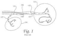
- Figure 1 shows a conventional (prior art) embolization treatment in the hepatic artery 106.
- Catheter 101 delivers embolization agents (beads) 102 in a hepatic artery 106, with a goal of embolizing a target organ 103. It is important that the forward flow (direction arrow 107) of blood is maintained during an infusion of embolization agents 102 because the forward flow is used to carry embolization agents 102 deep into the vascular bed of target organ 103.
- Embolization agents 102 are continuously injected until reflux of contrast agent is visualized in the distal area of the hepatic artery.
- a contrast agent may be added to embolization agents 102.
- the addition of the contrast agent allows for a visualization of the reflux of the contrast agent (shown by arrow 108), which is indicative of the reflux of embolization agents 102.
- the reflux may, undesirably, cause embolization agents 102 to be delivered into a collateral artery 105, which is proximal to the tip of catheter 101.
- embolization agents 102 in collateral artery 105 leads to non-target embolization in a non-target organ 104, which may be the other lobe of the liver, the stomach, small intestine, pancreas, gall bladder, or other organ.
- Non-targeted delivery of the embolic agent may have significant unwanted effects on the human body.
- non-targeted delivery of the embolic agent may have undesirable impacts on other organs including the stomach and small intestine.
- the non-targeted delivery of the embolic agent may embolize one or both ovaries leading to loss of menstrual cycle, subtle ovarian damage that may reduce fertility, early onset of menopause and in some cases substantial damage to the ovaries.
- Other unintended adverse events include unilateral deep buttock pain, buttock necrosis, and uterine necrosis.
- the microvalve infusion system 200 includes a dynamically adjustably filter valve 202 coupled to the distal end of a delivery catheter 204.
- the delivery catheter and filter valve extend within an outer catheter 206.
- the filter valve 202 is naturally spring biased by its construction of filamentary elements 208 to automatically partially expand within a vessel when it is deployed from the outer catheter 206, and is coated with a polymer coating 210 that has a pore size suitable to filter an embolic therapeutic agent.
- the filter valve 202 has an open distal end 212 and is coupled relative to the delivery catheter 204 such that an embolic agent infused through the delivery catheter 204 and out of the distal orifice 214 of the delivery catheter 204 exits within the interior 216 of the filter valve.
- an increase in fluid pressure results within the filter valve and causes the filter valve 202 to open, extend across a vessel, and thereby prevent reflux of the infused embolic agent.
- the downstream pressure in the vessel is increased which facilitates maximum uptake into the target tissue for therapeutically delivered agents.
- the filter valve is responsive to local pressure about the valve which thereby enables substantially unrestricted forward flow of blood in the vessel, and reduces or stops reflux (regurgitation or backward flow) of embolization agents which are introduced into the blood.
- the devices in US Patent No. 8,696,698 have certain issues that may not always be advantageous.
- the devices shown have a large distal diameter which limits trackability in tortuous branching vasculature.
- the distal end of the device in a collapsed, undeployed state is defined by the size of an outer catheter 206, which can be significantly larger than the outer diameter delivery catheter 204 that supports the filter valve 202 and significantly larger than the outer diameter of a guidewire (not shown) used to the guide the microvalve to the target location within the vessel.
- a guidewire not shown
- a further example of an endovascular microvalve device for use in a vessel during a therapy procedure is described in WO2015/148284 .
- the device includes an outer catheter, an inner catheter displaceable within the outer catheter, and a filter valve coupled to the distal ends of the inner and outer catheters.
- proximal and distal are defined in reference to the user's hand, with the term “proximal” being closer to the user's hand, and the term “distal” being further from the user's hand, unless alternate definitions are specifically provided.
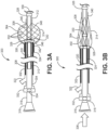
- FIG. 3B illustrates the microvalve device 300 in a non-deployed configuration and relative positioning of the three marker bands 326, 328, 330.
- the in vivo relative positions of the marker bands 326, 328, 330 indicates the displacement of the distal ends 306, 312 of the inner and outer catheters and the consequent configuration of the filter valve, as discussed in more detail below.
- the inner catheter 308 can be retracted relative to the outer catheter 302 (in the direction of arrow 382) to expand the filter valve 314 and cause the filter valve to assume (initially) a partially deployed configuration within the vessel in which the filter valve does not seal against the vessel wall 362.
- both upstream and downstream fluid flow passed the filter valve is possible based on relative fluid pressure at the proximal and distal sides of the filter valve.
- the inner catheter 308 can be further retracted relative to the outer catheter 302 (as indicated by arrow 384) to more fully expand the filter valve 314 to seal against the vessel wall 362.
- This configuration of the filter valve 314 is also shown in Fig. 7 .
- the proximal end of the filter valve 314 forms a distal facing plane or concave surface 368 (with it being understood that in the non-deployed configuration of the filter valve presents a distal facing convex or convexly conical surface), while the proximal facing surface remains unmodified in shape and is generally a smooth convex surface.
- the shape of the proximal surface of the deployed filter valve presents reduced resistance to blood passing the filter valve in the downstream direction when pressure is higher at the proximal surface than at the distal surface of the filter valve, but presents a distal facing surface at a different orientation and one that is substantially perpendicular to the vessel wall and has significant resistance to flow in the upstream direction so as to prevent reflux.
- a very small pressure differential e.g., 2.5 mmHg
- a small but relatively larger pressure differential e.g., 5 mmHg
- the valve is preferably capable of being configured into its closed position after the embolization treatment procedure is completed for removal from the patient.
- the valve is simply withdrawn in the deployed configuration.
- the inner catheter 308 is further retracted relative to the outer catheter 302 to invert a portion or all of the distal filter valve 348 into the proximal valve 346 to contain embolic agent that may potentially remain on the filter valve after the treatment.
- the inner catheter is even further retracted relative to the outer catheter (in the direction of arrow 386) to invert the entire filter valve 314 into the outer catheter 302 to fully contain any embolic agent that may potentially remain on the filter valve after the treatment.
- the filter valve when the radial force of expansion on the filter valve (i.e., the expansion force of the filter valve itself in addition to the force of pressure in the distal vessel over the distal surface area of the valve) is greater than the radial force of compression on the filter valve (i.e., force of pressure in the proximal vessel over the proximal surface area of the filter valve), the filter valve fully expands so that the valve assumes the open configuration.
- the radial force of expansion of the filter valve is chosen to be low (as described in more detail below) so that normal blood flow in the downstream distal direction will prevent the deployed filter valve from reaching the open condition.
- expansion force is different than the expansion forces of prior art stents, stent grafts, distal protection filters and other vascular devices, which have significantly higher radial forces of expansion. It is appreciated that expansion force is sufficiently low that it will not cause the inner catheter to move relative to the outer catheter; such relative movement is preferably effected only by the user of the device.
- the filter valve 314 has a radial force in the fully deployed position of less than 20mN, and even more preferably the filter valve has a radial force of approximately 10mN (where the term "approximately” as used herein is defined to mean ⁇ 20%) in the deployed position.
- the filter valve 314 when subject to an infusion pressure at the distal orifice 358 of the inner catheter, the filter valve 314 moves between deployed positions allowing downstream fluid passage (closed) and preventing fluid passage (open) in a static fluid (e.g., glycerin) having a viscosity approximately equal to the viscosity of blood (i.e., approximately 3.2 cP) in 0.067 second.
- a static fluid e.g., glycerin
- the time it takes to move from the closed position to the open position in a static fluid is called the "time constant".
- the filter valve 314 is arranged such that the time constant of the filter valve 314 in a fluid having the viscosity of blood is between 0.01 seconds and 1.00 seconds.
- the braid geometry and material properties of the filaments 350 are intimately related to the radial force and time constant of the filter valve. Since, according to one aspect of the invention, the filter valve is useful in a variety of vessels of different diameters and flow conditions, each implementation can have a unique optimization.
- the filter valve 314 has ten filaments 350, whereas in another embodiment, the filter valve has forty filaments 350. Any suitable number of filaments can be used.
- the diameter of the filaments are chosen in the range of 0.025 mm to 0.127 mm, although other diameters may be utilized.
- the pitch angle i.e., the crossing angle assumed by the braided filaments in the fully open deployed position
- the Young's modulus of the filament is at least 100 MPa, and more preferably at least 200 MPa.
- the filter valve 314 is chosen to have a pore size which is small enough to capture (filter) embolic agents in the blood stream as the blood passes through the filter valve.
- large embolic agents e.g., 500 ⁇ m
- a coating 364 is preferably added to the filaments 350, and more preferably to the formed braid structure, to provide the filter function. Such a separate polymeric filter is particularly useful where smaller embolic agents are utilized.
- the polymeric filter can be placed onto the braid structure by spraying, spinning, electrospinning, bonding with an adhesive, thermally fusing, mechanically capturing the braid, melt bonding, dip coating, or any other desired method.
- the polymeric coating 364 can either be a material with pores such as ePTFE, a solid material that has pores added such as polyurethane with laser drilled holes, or the filter coating can be a web of very thin filaments that are laid onto the braid. Where the coating 364 is a web of thin filaments, the characteristic pore size of the filter can be determined by attempting to pass beads of different diameters through the filter and finding which diameter beads are capable of passing through the filter in large quantities.
- the very thin filaments can be spun onto a rotating mandrel according to U.S.
- Patent 4,738,740 with the aid of an electrostatic field or in the absence of an electrostatic field or both.
- the filter thus formed can be adhered to the braid structure with an adhesive or the braid can be placed on the mandrel and the filter spun over it, or under it, or both over and under the braid to essentially capture it.
- the filter 364 can have some pores formed from spraying or electrospinning and then a secondary step where pores are laser drilled or formed by a secondary operation.
- a material capable of being electrostatically deposited or spun is used to form a filter on the braid, with the preferred material being capable of bonding to itself.
- the filter may be made of polyurethane, pellethane, polyolefin, polyester, fluoropolymers, acrylic polymers, acrylates, polycarbonates, or other suitable material.
- the polymer is spun onto the braid in a wet state, and therefore it is desirable that the polymer be soluble in a solvent.
- the filter is formed from polyurethane which is soluble in dimethylacetamide.
- the polymer material is spun onto the braid in a liquid state, with a preferred concentration of 5-10% solids for an electrostatic spin process and 15-25% solids for a wet spin process.
- the contrast agent may be used to indicate when the target site is fully embolized and can serve to identify a clinical endpoint of the embolization procedure. Therefore, according to one aspect of the invention, the valve allows the reflux of the contrast agent as an indicator of the clinical endpoint while preventing the reflux of the embolization agents at the same time. In addition, by allowing blood to flow back through the filter material, even at a relatively slow rate, backpressure on the distal side of the valve can be alleviated.
- the filter valve is also preferably provided with a hydrophilic coating, hydrophobic coating, or other coating that affects how proteins within blood adhere to the filter and specifically within the pores of the filter. More specifically, the coating is resistant to adhesion of blood proteins.
- a hydrophilic coating, hydrophobic coating, or other coating that affects how proteins within blood adhere to the filter and specifically within the pores of the filter. More specifically, the coating is resistant to adhesion of blood proteins.
- One coating that has been used successfully is ANTI-FOG COATING 7-TS-13 available from Hydromer, Inc. of Branchburg, NJ, which can be applied to the filter by, e.g., dipping, spraying, roll or flow coating.
- proteins in the blood will almost immediately fill the pores during use.
- the proteins on the coated porous filter operate as a pressure safety valve, such that the pores are filled with the proteins when subject to an initial fluid pressure greater than the blood vessel pressure, but the proteins are displaced from the pores and the pores are opened to blood flow at higher pressures such as a designated threshold pressure.
- the designated threshold pressure is determined to prevent damage to the tissue and organs, and injury to the patient.
- this system allows a pressure greater than the vessel pressure while limiting very high pressures which may be unsafe to the patient.
- the system provides pressure regulation which is not possible with other occlusive devices, including balloons. Notwithstanding the advantage of the above, it is not a requirement of the invention that the filter be constructed to allow either blood or contrast agent to pass through in the upstream ⁇ reflux' direction under any determined pressure.
- the filter valve is designed to permit the blood to reflux through the pores of the filter valve while still blocking the passage of the embolic agent.
- An exemplar threshold pressure is 180 mmHg on the distal surface of the filter valve, although the device can be designed to accommodate other threshold pressures.
- Such can be effected, at least in part, by the use of an appropriate coating on the filter that facilitates removal of the blood proteins from within the filter pores when subject to threshold pressure. This prevents the vessel in which the device is inserted from being subject to a pressure that could otherwise result in damage. Nevertheless, it is not necessary that blood and contrast agent be permitted to reflux through the valve.
- the filter coating 350 is preferably provided as a homogenous coating of filaments, with the proximal and distal portions 346, 348 of the filter valve 314 having a uniform coating construct.
- the filter valve 314 is provided in the form of a closed shape, with its proximal end 346 fused to the outer catheter 302, and its distal end 348 fused to the inner catheter 308, it is appreciated that any fluid or agent passing from the vessel and through the filter must through two similar layers of the filter; i.e., a layer at the proximal side of the filter valve and a layer at the distal side of the filter valve.
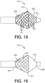
- the filter valve has a different radial force at its proximal portion relative to its distal portion. This difference in radial force to enable behavior that is dependent on the direction of the flow (i.e. the valve behavior). It is preferred that the distal portion have lower radial force than the proximal portion, as described in Figures 11-16 , as follows.
- the difference in radial force allows the filter valve to have different performance in forward flow compared to backflow.
- forward flow the device remains in a conical shape allowing fluid around it.
- backflow the very weak structure collapses inward, allowing fluid pressure to seal the device against the vessel wall and reducing backflow.
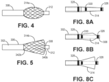
- a filter valve 614 is shown (not covered by the claimed invention).
- the filter valve has a non-porous membrane coating 690 at its inner surface 692 of the proximal portion, and a filter coating 650 on the outer surface of at least the distal portion of the filter valve, and preferably the entire filter valve.
- the combination of a non-porous membrane and porous membrane on the proximal portion both increases antegrade flow and radial strength in forward flow while the porous membrane on the distal portion reduces radial strength and allows flow into the filter valve in back flow to seal the vessel and block the reflux of embolic agents.
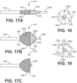
- the filter valve 914 includes a proximal filamentary braided portion 926, preferably coated with a polymeric filter material 927, and a distal portion comprising a polymeric filter material 928.
- the proximal and distal portions 926, 928 are preferably demarcated by the circumference about the maximum diameter 933 of the filter valve.
- the distal portion 928 is braidless; i.e., does not include any of the self-expanding filamentary structure.
- the filter valve 914 may be formed by positioning the filamentary braid for the proximal portion 926 on a mandrel (not shown), and spray coating a porous polymeric membranous material over the proximal braid and also further distally onto the mandrel--where no braid is provided-for construction of the braidless distal portion 928. After curing, the construct is removed from the mandrel. Once the proximal portion 926 of the filter valve 914 is coupled to the outer catheter 904, and the distal portion 928 of the filter valve 914 is coupled to the inner catheter 908, the filter valve has preferred properties. At the distal portion 928, the filter valve 914 is structured substantially similarly to a fabric.
- the distal portion 928 of the filter valve 914 is strong under tensile force; however, when the inner catheter 908 is retracted relative to the outer catheter 904 and the distal portion 928 is placed under compression, the distal portion of the filter valve is floppy under compression force.
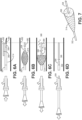
- the inner catheter 1008 is distally displaced relative to the outer catheter 1004 to reduce the diameter of the filter valve 104, as shown in Fig. 17A for insertion into a patient.
- This configuration facilitates tracking over a guidewire to a location of therapeutic treatment.
- the spiral filament configuration of the distal portion 1028 of the filter valve offers a lower profile at the distal end of the device.
- the guidewire can be removed. Then, the user begins to proximally displace the inner catheter 1008 relative to the outer catheter 1004 to retract the distal end portion 1028 relative to the proximal braided portion 1026 in preparation for treatment ( Fig.
- the physician will track and advance the inner catheter of the microvalve device over a guidewire out to a target location, and then remove the guidewire.
- An embolic agent is then infused through the inner catheter to deliver the agent distal of the microvalve, and the device is utilized as intended and in accord with its specific structural design.
- the physician has two options to prepare or configure the microvalve device for removal.
- the inner catheter can be pushed or otherwise displaced forward relative to the distal end of the outer catheter to result in collapse of the microvalve to reduce its diameter to facilitate its removal from the vessels of the body.
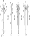
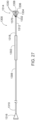
- the device 1200 includes a flexible infusion catheter 1208 having a proximal end 1210 provided with an infusion hub 1216, and a distal end 1212 opening at an orifice 1258.
- a filter valve 1214 is coupled to the distal end 1212 of the infusion catheter 1208.
- the filter valve 1214 in this embodiment has a braided construct from its proximal end to its distal end.
- the braided construct 1120 may be made of metal, including Nitinol, and/or polymer filaments.
- a polymeric filter is coated on a proximal portion 1234 of the filter valve; preferably, the distal portion 1236 of the braided construct is free of the polymeric filter.
- the proximal end 1224 of the filter valve 1214 is fixed to the outside of the catheter 1208, and the distal end of the filter valve 1214 forms a collar 1230.
- the collar 1230 is free floating about the outside of the catheter and can longitudinally displace relative to the proximal end 1224 of the filter valve 1214.
- An introducer sleeve (or outer catheter) 1202 is advanceable over the infusion catheter 1208 and filter valve 1214, to collapse the filter valve (as shown in Fig.
- the filter-coated proximal portion 1234 of the filter valve will expand under pressure into a wide open configuration completely across the vessel 1262 so as to form a barrier to upstream flow, such as occurs when an infusate 1288 is injected under pressure through the lumen and out of the distal orifice 1258.
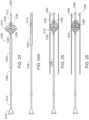
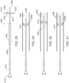
- proximal and central portions 1332, 1334 of the strands are coated in a polymeric filter 1370 that extends between and across the strands 1330.
- distal portions 1336 of the strands may also be coated in the polymeric filter, although the illustrated filter valve is provided with an uncoated distal portion.
- Fig. 29 when the filter valve 1414 is located at a target location within a vessel, the filter valve 1414 expands outward to the vessel wall 1462 and has an expanded diameter larger than the vessel diameter.
- the distal surface 1436a of the second disc 1436 should present a concave surface to block and capture embolic agent infused through the distal orifice 1458, as shown in Fig. 29 .
- the configuration of the distal surface 1436a can be tested by injecting a contrast agent 1490 through the infusion catheter 1408. If the contrast agent is seen refluxing past the filter valve 1414, it may be concluded that the orientation is inverted, which would not provide an adequate barrier to reflux of a pressurized embolic agent. ( Fig.
- the catheter body and mesh may be separately labeled for easy visualization under fluoroscopy.
- the catheter body can be labeled by use of any means known in the art; for example, compounding a radio-opaque material into the catheter tubing.
- the radio-opaque material can be barium sulfate, bismuth subcarbonate or other material.
- radio-opaque medium can be compounded into the materials of the braid and the filter.
- one or more of the filaments may be chosen to be made of a radio-opaque material such as platinum iridium.
Landscapes
- Health & Medical Sciences (AREA)
- Life Sciences & Earth Sciences (AREA)
- Veterinary Medicine (AREA)
- Animal Behavior & Ethology (AREA)
- Engineering & Computer Science (AREA)
- Biomedical Technology (AREA)
- Heart & Thoracic Surgery (AREA)
- Public Health (AREA)
- General Health & Medical Sciences (AREA)
- Vascular Medicine (AREA)
- Surgery (AREA)
- Oral & Maxillofacial Surgery (AREA)
- Cardiology (AREA)
- Transplantation (AREA)
- Molecular Biology (AREA)
- Medical Informatics (AREA)
- Nuclear Medicine, Radiotherapy & Molecular Imaging (AREA)
- Reproductive Health (AREA)
- Anesthesiology (AREA)
- Hematology (AREA)
- Biophysics (AREA)
- Pulmonology (AREA)
- Pathology (AREA)
- Surgical Instruments (AREA)
- Infusion, Injection, And Reservoir Apparatuses (AREA)
- Media Introduction/Drainage Providing Device (AREA)
Priority Applications (1)
| Application Number | Priority Date | Filing Date | Title |
|---|---|---|---|
| EP24179942.8A EP4450025A3 (en) | 2017-03-20 | 2018-03-13 | Dynamic reconfigurable microvalve protection device |
Applications Claiming Priority (2)
| Application Number | Priority Date | Filing Date | Title |
|---|---|---|---|
| US15/464,036 US10588636B2 (en) | 2017-03-20 | 2017-03-20 | Dynamic reconfigurable microvalve protection device |
| PCT/US2018/022171 WO2018175148A1 (en) | 2017-03-20 | 2018-03-13 | Dynamic reconfigurable microvalve protection device |
Related Child Applications (1)
| Application Number | Title | Priority Date | Filing Date |
|---|---|---|---|
| EP24179942.8A Division EP4450025A3 (en) | 2017-03-20 | 2018-03-13 | Dynamic reconfigurable microvalve protection device |
Publications (3)
| Publication Number | Publication Date |
|---|---|
| EP3600495A1 EP3600495A1 (en) | 2020-02-05 |
| EP3600495A4 EP3600495A4 (en) | 2020-09-16 |
| EP3600495B1 true EP3600495B1 (en) | 2024-07-03 |
Family
ID=63521361
Family Applications (2)
| Application Number | Title | Priority Date | Filing Date |
|---|---|---|---|
| EP18770345.9A Active EP3600495B1 (en) | 2017-03-20 | 2018-03-13 | Dynamic reconfigurable microvalve protection device |
| EP24179942.8A Pending EP4450025A3 (en) | 2017-03-20 | 2018-03-13 | Dynamic reconfigurable microvalve protection device |
Family Applications After (1)
| Application Number | Title | Priority Date | Filing Date |
|---|---|---|---|
| EP24179942.8A Pending EP4450025A3 (en) | 2017-03-20 | 2018-03-13 | Dynamic reconfigurable microvalve protection device |
Country Status (8)
Families Citing this family (24)
| Publication number | Priority date | Publication date | Assignee | Title |
|---|---|---|---|---|
| US9539081B2 (en) | 2009-12-02 | 2017-01-10 | Surefire Medical, Inc. | Method of operating a microvalve protection device |
| US9968740B2 (en) | 2014-03-25 | 2018-05-15 | Surefire Medical, Inc. | Closed tip dynamic microvalve protection device |
| US20160287839A1 (en) | 2015-03-31 | 2016-10-06 | Surefire Medical, Inc. | Apparatus and Method for Infusing an Immunotherapy Agent to a Solid Tumor for Treatment |
| US20220016338A1 (en) * | 2020-07-15 | 2022-01-20 | Cerebral Therapeutics, Inc. | Implantable cranial medical device |
| US10780250B1 (en) | 2016-09-19 | 2020-09-22 | Surefire Medical, Inc. | System and method for selective pressure-controlled therapeutic delivery |
| US11400263B1 (en) | 2016-09-19 | 2022-08-02 | Trisalus Life Sciences, Inc. | System and method for selective pressure-controlled therapeutic delivery |
| US11850398B2 (en) | 2018-08-01 | 2023-12-26 | Trisalus Life Sciences, Inc. | Systems and methods for pressure-facilitated therapeutic agent delivery |
| US11338117B2 (en) * | 2018-10-08 | 2022-05-24 | Trisalus Life Sciences, Inc. | Implantable dual pathway therapeutic agent delivery port |
| US20200383688A1 (en) * | 2019-06-04 | 2020-12-10 | Surefire Medical, Inc. | Atraumatic Occlusive System with Compartment for Measurement of Vascular Pressure Change |
| US11376013B2 (en) * | 2019-11-18 | 2022-07-05 | DePuy Synthes Products, Inc. | Implant delivery system with braid cup formation |
| US20230374523A1 (en) | 2020-09-22 | 2023-11-23 | Trisalus Life Sciences, Inc. | Cancer therapy using toll-like receptor agonists |
| CA3196273A1 (en) | 2020-09-22 | 2022-03-31 | Trisalus Life Sciences, Inc. | Cancer therapy using toll-like receptor agonists |
| CN112316276A (zh) * | 2020-12-03 | 2021-02-05 | 珠海通桥医疗科技有限公司 | 微导管 |
| WO2022212690A1 (en) | 2021-04-01 | 2022-10-06 | Trisalus Life Sciences, Inc. | Cancer therapy using toll-like receptor agonists |
| WO2022221869A1 (en) * | 2021-04-15 | 2022-10-20 | Retriever Medical, Inc. | Catheters with expandable and collapsible lumens |
| JP2024515881A (ja) | 2021-04-29 | 2024-04-10 | トリサルース・ライフ・サイエンシズ・インコーポレイテッド | チェックポイント阻害剤を使用したがん治療 |
| US20220346931A1 (en) * | 2021-05-03 | 2022-11-03 | Adient Medical, Inc. | Delivery system for a medical device |
| CN113599663B (zh) * | 2021-08-12 | 2023-10-20 | 杭州未名信科科技有限公司 | 血管植入式药物灌注导管 |
| US20240238558A9 (en) * | 2022-10-19 | 2024-07-18 | Trisalus Life Sciences, Inc. | Therapeutic treatment device with braided microvalve occluder |
| US20240225654A9 (en) * | 2022-10-20 | 2024-07-11 | Trisalus Life Sciences, Inc. | Therapeutic treatment device with braided microvalve occluder having collapsible cover |
| US20240164788A1 (en) * | 2022-11-22 | 2024-05-23 | Trisalus Life Sciences, Inc. | Therapeutic treatment device with braided-strand microvalve occluder having modified filter coating |
| US20240225831A1 (en) * | 2023-01-09 | 2024-07-11 | Excision Medical, Inc. | Surgical system for a heart valve |
| WO2024192503A1 (en) * | 2023-03-17 | 2024-09-26 | Mg Stroke Analytics Inc. | Catheter system having sealing system for preventing back-flow within cerebral vessels |
| WO2025145211A1 (en) * | 2023-12-30 | 2025-07-03 | Trisalus Life Sciences, Inc. | Vessel occluder advanceable over an infusion catheter |
Family Cites Families (240)
| Publication number | Priority date | Publication date | Assignee | Title |
|---|---|---|---|---|
| DE2821048C2 (de) | 1978-05-13 | 1980-07-17 | Willy Ruesch Gmbh & Co Kg, 7053 Kernen | Medizinisches Instrument |
| US4261341A (en) | 1979-06-08 | 1981-04-14 | Hakim Company Limited | Method and apparatus for the treatment of ascites |
| US4311587A (en) | 1979-12-10 | 1982-01-19 | Japan Foundation For Artificial Organs | Filter arrangement denying bacteria entry to peritoneum |
| SE445884B (sv) | 1982-04-30 | 1986-07-28 | Medinvent Sa | Anordning for implantation av en rorformig protes |
| US4714460A (en) | 1983-07-29 | 1987-12-22 | Reynaldo Calderon | Methods and systems for retrograde perfusion in the body for curing it of the disease or immume deficiency |
| US4883459A (en) | 1983-07-29 | 1989-11-28 | Reynaldo Calderon | Retrograde perfusion |
| US4840542A (en) | 1985-03-27 | 1989-06-20 | Quest Medical, Inc. | Infusion pump with direct pressure sensing |
| US4738740A (en) | 1985-11-21 | 1988-04-19 | Corvita Corporation | Method of forming implantable vascular grafts |
| US4800016A (en) | 1986-11-24 | 1989-01-24 | The University Of Michigan | Extracorporeal blood de-heparinization system |
| DE68911651T2 (de) | 1988-05-16 | 1994-05-19 | Terumo Corp | Subkutan implantierter katheterzusammenbau. |
| US5234425A (en) | 1989-03-03 | 1993-08-10 | Thomas J. Fogarty | Variable diameter sheath method and apparatus for use in body passages |
| DE8910603U1 (de) | 1989-09-06 | 1989-12-07 | Günther, Rolf W., Prof. Dr. | Vorrichtung zum Ausbringen von Blutgerinnseln aus Arterien und Venen |
| US5034001A (en) | 1989-09-08 | 1991-07-23 | Advanced Cardiovascular Systems, Inc. | Method of repairing a damaged blood vessel with an expandable cage catheter |
| FR2652267B1 (fr) | 1989-09-27 | 1997-12-12 | Prothia Sarl | Dispositif de catheter et filtre pour veine cave. |
| US5030199A (en) | 1989-12-11 | 1991-07-09 | Medical Engineering Corporation | Female incontinence control device with magnetically operable valve and method |
| US5221261A (en) | 1990-04-12 | 1993-06-22 | Schneider (Usa) Inc. | Radially expandable fixation member |
| US5071407A (en) | 1990-04-12 | 1991-12-10 | Schneider (U.S.A.) Inc. | Radially expandable fixation member |
| DE9109006U1 (de) | 1991-07-22 | 1991-10-10 | Schmitz-Rode, Thomas, Dipl.-Ing. Dr.med., 5100 Aachen | Atherektomie-Angioplastie-Katheter |
| ES2086633T3 (es) | 1992-02-03 | 1996-07-01 | Schneider Europ Ag | Cateter con un sustentaculo vascular. |
| FR2688401B1 (fr) | 1992-03-12 | 1998-02-27 | Thierry Richard | Endoprothese expansible pour organe tubulaire humain ou animal, et outil de mise en place. |
| US5897567A (en) | 1993-04-29 | 1999-04-27 | Scimed Life Systems, Inc. | Expandable intravascular occlusion material removal devices and methods of use |
| US5411478A (en) | 1993-07-12 | 1995-05-02 | Michael E. Stillabower | Angioplasty apparatus and process |
| US5397307A (en) | 1993-12-07 | 1995-03-14 | Schneider (Usa) Inc. | Drug delivery PTCA catheter and method for drug delivery |
| US5419763B1 (en) | 1994-01-04 | 1997-07-15 | Cor Trak Medical Inc | Prostatic drug-delivery catheter |
| EP0741585A1 (en) | 1994-01-21 | 1996-11-13 | Brown University Research Foundation | Biocompatible implants |
| US5484412A (en) | 1994-04-19 | 1996-01-16 | Pierpont; Brien E. | Angioplasty method and means for performing angioplasty |
| US5836905A (en) | 1994-06-20 | 1998-11-17 | Lemelson; Jerome H. | Apparatus and methods for gene therapy |
| US5899882A (en) | 1994-10-27 | 1999-05-04 | Novoste Corporation | Catheter apparatus for radiation treatment of a desired area in the vascular system of a patient |
| US5688237A (en) | 1995-05-04 | 1997-11-18 | Cedars-Sinai Medical Center | Implantable catheter and method of use |
| US6994689B1 (en) * | 1995-06-05 | 2006-02-07 | Medtronic Vascular, Inc. | Occlusion of a vessel |
| WO1997027893A1 (en) * | 1996-02-02 | 1997-08-07 | Transvascular, Inc. | Methods and apparatus for blocking flow through blood vessels |
| US5895398A (en) | 1996-02-02 | 1999-04-20 | The Regents Of The University Of California | Method of using a clot capture coil |
| EP0897288A4 (en) | 1996-05-14 | 2000-04-05 | Embol X Inc | AORTIC occluder with associated filter and method of use during cardiac surgery |
| US5662671A (en) | 1996-07-17 | 1997-09-02 | Embol-X, Inc. | Atherectomy device having trapping and excising means for removal of plaque from the aorta and other arteries |
| US5957974A (en) | 1997-01-23 | 1999-09-28 | Schneider (Usa) Inc | Stent graft with braided polymeric sleeve |
| US5893869A (en) | 1997-02-19 | 1999-04-13 | University Of Iowa Research Foundation | Retrievable inferior vena cava filter system and method for use thereof |
| US5814064A (en) | 1997-03-06 | 1998-09-29 | Scimed Life Systems, Inc. | Distal protection device |
| US6974469B2 (en) | 1997-03-06 | 2005-12-13 | Scimed Life Systems, Inc. | Distal protection device and method |
| US6152946A (en) | 1998-03-05 | 2000-11-28 | Scimed Life Systems, Inc. | Distal protection device and method |
| US6676682B1 (en) | 1997-05-08 | 2004-01-13 | Scimed Life Systems, Inc. | Percutaneous catheter and guidewire having filter and medical device deployment capabilities |
| US5911734A (en) | 1997-05-08 | 1999-06-15 | Embol-X, Inc. | Percutaneous catheter and guidewire having filter and medical device deployment capabilities |
| US6258120B1 (en) | 1997-12-23 | 2001-07-10 | Embol-X, Inc. | Implantable cerebral protection device and methods of use |
| US6059745A (en) | 1997-05-20 | 2000-05-09 | Gelbfish; Gary A. | Thrombectomy device and associated method |
| DE59711669D1 (de) | 1997-06-23 | 2004-07-01 | Schneider Europ Gmbh Buelach | Katheteranordnung |
| US6395014B1 (en) | 1997-09-26 | 2002-05-28 | John A. Macoviak | Cerebral embolic protection assembly and associated methods |
| US6361545B1 (en) | 1997-09-26 | 2002-03-26 | Cardeon Corporation | Perfusion filter catheter |
| BR9813935A (pt) | 1997-11-07 | 2000-09-19 | Salviac Ltd | Dispositivos de filtragem vascular para remoção de material embólico de fluidos corpóreos |
| US20040260333A1 (en) | 1997-11-12 | 2004-12-23 | Dubrul William R. | Medical device and method |
| US6764461B2 (en) | 1997-12-01 | 2004-07-20 | Scimed Life Systems, Inc. | Catheter system for the delivery of a low volume bolus |
| JP2002502626A (ja) | 1998-02-10 | 2002-01-29 | アーテミス・メディカル・インコーポレイテッド | 補足装置およびその使用方法 |
| AU2994499A (en) | 1998-03-04 | 1999-09-20 | Bioguide Consulting, Inc. | Guidewire filter device |
| EP1061984B2 (de) | 1998-03-09 | 2010-03-03 | Kimberly-Clark Worldwide, Inc. | Trachealbeatmungsvorrichtung |
| US6960222B2 (en) * | 1998-03-13 | 2005-11-01 | Gore Enterprise Holdins, Inc. | Catheter having a funnel-shaped occlusion balloon of uniform thickness and methods of manufacture |
| US6645222B1 (en) | 1998-05-13 | 2003-11-11 | Arteria Medical Science, Inc. | Puncture resistant branch artery occlusion device and methods of use |
| US6908474B2 (en) | 1998-05-13 | 2005-06-21 | Gore Enterprise Holdings, Inc. | Apparatus and methods for reducing embolization during treatment of carotid artery disease |
| US6936060B2 (en) | 1998-05-13 | 2005-08-30 | Arteria Medical Sciences, Inc. | Apparatus and methods for removing emboli during a surgical procedure |
| US6582396B1 (en) | 1998-05-13 | 2003-06-24 | Arteria Medical Science, Inc. | Puncture resistant balloon for use in carotid artery procedures and methods of use |
| JP2002536029A (ja) | 1998-05-21 | 2002-10-29 | ザ ガバメント オブ ザ ユナイテッドステイツ オブ アメリカ アズ リプレゼンテッド バイ ザ セクレタリー デパートメント オブ ヘルス アンド ヒューマン サービシーズ ザ ナショナル インステ | 治療物質の圧力介在型選択的送達のための方法およびカニューレ |
| US6306163B1 (en) | 1998-08-04 | 2001-10-23 | Advanced Cardiovascular Systems, Inc. | Assembly for collecting emboli and method of use |
| US7118600B2 (en) | 1998-08-31 | 2006-10-10 | Wilson-Cook Medical, Inc. | Prosthesis having a sleeve valve |
| US6746489B2 (en) | 1998-08-31 | 2004-06-08 | Wilson-Cook Medical Incorporated | Prosthesis having a sleeve valve |
| US6051014A (en) | 1998-10-13 | 2000-04-18 | Embol-X, Inc. | Percutaneous filtration catheter for valve repair surgery and methods of use |
| US6165199A (en) | 1999-01-12 | 2000-12-26 | Coaxia, Inc. | Medical device for removing thromboembolic material from cerebral arteries and methods of use |
| US6896690B1 (en) | 2000-01-27 | 2005-05-24 | Viacor, Inc. | Cardiac valve procedure methods and devices |
| US6231551B1 (en) | 1999-03-01 | 2001-05-15 | Coaxia, Inc. | Partial aortic occlusion devices and methods for cerebral perfusion augmentation |
| US6743196B2 (en) | 1999-03-01 | 2004-06-01 | Coaxia, Inc. | Partial aortic occlusion devices and methods for cerebral perfusion augmentation |
| DE60031272T2 (de) | 1999-06-02 | 2007-05-31 | Boston Scientific Ltd., St. Michael | Arzneimittelabgabevorrichtung |
| US6339718B1 (en) | 1999-07-30 | 2002-01-15 | Medrad, Inc. | Programmable injector control |
| US7229462B2 (en) * | 1999-07-30 | 2007-06-12 | Angioguard, Inc. | Vascular filter system for carotid endarterectomy |
| US6245087B1 (en) * | 1999-08-03 | 2001-06-12 | Embol-X, Inc. | Variable expansion frame system for deploying medical devices and methods of use |
| US6235044B1 (en) | 1999-08-04 | 2001-05-22 | Scimed Life Systems, Inc. | Percutaneous catheter and guidewire for filtering during ablation of mycardial or vascular tissue |
| US6168579B1 (en) | 1999-08-04 | 2001-01-02 | Scimed Life Systems, Inc. | Filter flush system and methods of use |
| US6551303B1 (en) | 1999-10-27 | 2003-04-22 | Atritech, Inc. | Barrier device for ostium of left atrial appendage |
| US6652555B1 (en) | 1999-10-27 | 2003-11-25 | Atritech, Inc. | Barrier device for covering the ostium of left atrial appendage |
| US6689150B1 (en) | 1999-10-27 | 2004-02-10 | Atritech, Inc. | Filter apparatus for ostium of left atrial appendage |
| US6371971B1 (en) | 1999-11-15 | 2002-04-16 | Scimed Life Systems, Inc. | Guidewire filter and methods of use |
| GB9928905D0 (en) | 1999-12-08 | 2000-02-02 | Aortech Europ Ltd | Prosthesis |
| WO2001045592A1 (en) | 1999-12-23 | 2001-06-28 | Percusurge, Inc. | Vascular filters with radiopaque markings |
| US6660021B1 (en) | 1999-12-23 | 2003-12-09 | Advanced Cardiovascular Systems, Inc. | Intravascular device and system |
| US6645220B1 (en) | 1999-12-30 | 2003-11-11 | Advanced Cardiovascular Systems, Inc. | Embolic protection system and method including and embolic-capturing filter |
| US6540722B1 (en) | 1999-12-30 | 2003-04-01 | Advanced Cardiovascular Systems, Inc. | Embolic protection devices |
| US6695813B1 (en) | 1999-12-30 | 2004-02-24 | Advanced Cardiovascular Systems, Inc. | Embolic protection devices |
| US6383206B1 (en) | 1999-12-30 | 2002-05-07 | Advanced Cardiovascular Systems, Inc. | Embolic protection system and method including filtering elements |
| US6702834B1 (en) | 1999-12-30 | 2004-03-09 | Advanced Cardiovascular Systems, Inc. | Embolic protection devices |
| US6663613B1 (en) | 2000-01-25 | 2003-12-16 | Bacchus Vascular, Inc. | System and methods for clot dissolution |
| US7749245B2 (en) | 2000-01-27 | 2010-07-06 | Medtronic, Inc. | Cardiac valve procedure methods and devices |
| US6443926B1 (en) | 2000-02-01 | 2002-09-03 | Harold D. Kletschka | Embolic protection device having expandable trap |
| US7322957B2 (en) | 2000-02-01 | 2008-01-29 | Harold D. Kletschka | Angioplasty device and method of making same |
| AU2001249153A1 (en) | 2000-03-10 | 2001-09-24 | Peter Besselink | Vascular embolism preventon device employing filters |
| GB2369575A (en) | 2000-04-20 | 2002-06-05 | Salviac Ltd | An embolic protection system |
| US6706053B1 (en) | 2000-04-28 | 2004-03-16 | Advanced Cardiovascular Systems, Inc. | Nitinol alloy design for sheath deployable and re-sheathable vascular devices |
| US6890315B1 (en) | 2000-05-23 | 2005-05-10 | Chf Solutions, Inc. | Method and apparatus for vein fluid removal in heart failure |
| US6478783B1 (en) | 2000-05-26 | 2002-11-12 | H. Robert Moorehead | Anti-sludge medication ports and related methods |
| US8435225B2 (en) | 2000-06-02 | 2013-05-07 | Fox Hollow Technologies, Inc. | Embolization protection system for vascular procedures |
| US6939362B2 (en) | 2001-11-27 | 2005-09-06 | Advanced Cardiovascular Systems, Inc. | Offset proximal cage for embolic filtering devices |
| AU2000260532A1 (en) | 2000-06-20 | 2002-01-02 | CHF Soultions, Inc | Apparatus and method for perfusing the kidney with venous blood |
| AU2001273088A1 (en) | 2000-06-30 | 2002-01-30 | Viacor Incorporated | Intravascular filter with debris entrapment mechanism |
| US6685672B1 (en) | 2000-07-13 | 2004-02-03 | Edwards Lifesciences Corporation | Multi-balloon drug delivery catheter for angiogenesis |
| US6964670B1 (en) | 2000-07-13 | 2005-11-15 | Advanced Cardiovascular Systems, Inc. | Embolic protection guide wire |
| US6855154B2 (en) | 2000-08-11 | 2005-02-15 | University Of Louisville Research Foundation, Inc. | Endovascular aneurysm treatment device and method |
| US6569146B1 (en) | 2000-08-18 | 2003-05-27 | Scimed Life Systems, Inc. | Method and apparatus for treating saphenous vein graft lesions |
| IL155015A0 (en) | 2000-09-21 | 2003-10-31 | Atritech Inc | Apparatus for implanting devices in atrial appendages |
| US6416495B1 (en) | 2000-10-10 | 2002-07-09 | Science Incorporated | Implantable fluid delivery device for basal and bolus delivery of medicinal fluids |
| US6537294B1 (en) | 2000-10-17 | 2003-03-25 | Advanced Cardiovascular Systems, Inc. | Delivery systems for embolic filter devices |
| WO2002056796A1 (en) | 2000-12-01 | 2002-07-25 | Nephros Therapeutics, Inc. | Intravascular blood conditioning device and use thereof |
| US20020128680A1 (en) | 2001-01-25 | 2002-09-12 | Pavlovic Jennifer L. | Distal protection device with electrospun polymer fiber matrix |
| US7226464B2 (en) | 2001-03-01 | 2007-06-05 | Scimed Life Systems, Inc. | Intravascular filter retrieval device having an actuatable dilator tip |
| US7214237B2 (en) | 2001-03-12 | 2007-05-08 | Don Michael T Anthony | Vascular filter with improved strength and flexibility |
| US6818006B2 (en) | 2001-04-03 | 2004-11-16 | Medtronic Vascular, Inc. | Temporary intraluminal filter guidewire |
| US6706055B2 (en) | 2001-04-03 | 2004-03-16 | Medtronic Ave Inc. | Guidewire apparatus for temporary distal embolic protection |
| US6866677B2 (en) | 2001-04-03 | 2005-03-15 | Medtronic Ave, Inc. | Temporary intraluminal filter guidewire and methods of use |
| US7044958B2 (en) | 2001-04-03 | 2006-05-16 | Medtronic Vascular, Inc. | Temporary device for capturing embolic material |
| US6911036B2 (en) | 2001-04-03 | 2005-06-28 | Medtronic Vascular, Inc. | Guidewire apparatus for temporary distal embolic protection |
| US6645223B2 (en) | 2001-04-30 | 2003-11-11 | Advanced Cardiovascular Systems, Inc. | Deployment and recovery control systems for embolic protection devices |
| US6746469B2 (en) | 2001-04-30 | 2004-06-08 | Advanced Cardiovascular Systems, Inc. | Balloon actuated apparatus having multiple embolic filters, and method of use |
| US6830579B2 (en) | 2001-05-01 | 2004-12-14 | Coaxia, Inc. | Devices and methods for preventing distal embolization using flow reversal and perfusion augmentation within the cerebral vasculature |
| US6635070B2 (en) | 2001-05-21 | 2003-10-21 | Bacchus Vascular, Inc. | Apparatus and methods for capturing particulate material within blood vessels |
| US6520183B2 (en) | 2001-06-11 | 2003-02-18 | Memorial Sloan-Kettering Cancer Center | Double endobronchial catheter for one lung isolation anesthesia and surgery |
| US7338510B2 (en) | 2001-06-29 | 2008-03-04 | Advanced Cardiovascular Systems, Inc. | Variable thickness embolic filtering devices and method of manufacturing the same |
| US6533800B1 (en) | 2001-07-25 | 2003-03-18 | Coaxia, Inc. | Devices and methods for preventing distal embolization using flow reversal in arteries having collateral blood flow |
| US6902540B2 (en) | 2001-08-22 | 2005-06-07 | Gerald Dorros | Apparatus and methods for treating stroke and controlling cerebral flow characteristics |
| US6656351B2 (en) | 2001-08-31 | 2003-12-02 | Advanced Cardiovascular Systems, Inc. | Embolic protection devices one way porous membrane |
| US9242069B2 (en) | 2001-09-30 | 2016-01-26 | Scicotec Gmbh | Method for control of stem cell injection into the body |
| US20030078614A1 (en) * | 2001-10-18 | 2003-04-24 | Amr Salahieh | Vascular embolic filter devices and methods of use therefor |
| EP1438085B1 (en) | 2001-10-25 | 2008-10-15 | Emory University | Catheter for modified perfusion |
| US6755813B2 (en) | 2001-11-20 | 2004-06-29 | Cleveland Clinic Foundation | Apparatus and method for performing thrombolysis |
| US6837898B2 (en) | 2001-11-30 | 2005-01-04 | Advanced Cardiovascular Systems, Inc. | Intraluminal delivery system for an attachable treatment device |
| ES2399091T3 (es) | 2001-12-05 | 2013-03-25 | Keystone Heart Ltd. | Dispositivo endovascular para atrapamiento de materia en forma de partículas y método para su uso |
| US7241304B2 (en) | 2001-12-21 | 2007-07-10 | Advanced Cardiovascular Systems, Inc. | Flexible and conformable embolic filtering devices |
| US20030125790A1 (en) | 2001-12-27 | 2003-07-03 | Vitaly Fastovsky | Deployment device, system and method for medical implantation |
| US6641572B2 (en) | 2002-01-24 | 2003-11-04 | Michael Cherkassky | Interstitial space saturation |
| US7344549B2 (en) | 2002-01-31 | 2008-03-18 | Advanced Cardiovascular Systems, Inc. | Expandable cages for embolic filtering devices |
| US8062251B2 (en) | 2002-02-01 | 2011-11-22 | Vascular Designs, Inc. | Multi-function catheter and use thereof |
| SE0201053D0 (sv) | 2002-04-08 | 2002-04-08 | Corline Systems Ab | Stent assembly and device for application thereof |
| US7853333B2 (en) | 2002-04-08 | 2010-12-14 | Ardian, Inc. | Methods and apparatus for multi-vessel renal neuromodulation |
| US7653438B2 (en) | 2002-04-08 | 2010-01-26 | Ardian, Inc. | Methods and apparatus for renal neuromodulation |
| US7620451B2 (en) | 2005-12-29 | 2009-11-17 | Ardian, Inc. | Methods and apparatus for pulsed electric field neuromodulation via an intra-to-extravascular approach |
| US7162303B2 (en) | 2002-04-08 | 2007-01-09 | Ardian, Inc. | Renal nerve stimulation method and apparatus for treatment of patients |
| US7503904B2 (en) | 2002-04-25 | 2009-03-17 | Cardiac Pacemakers, Inc. | Dual balloon telescoping guiding catheter |
| JP4583032B2 (ja) | 2002-04-25 | 2010-11-17 | ザ ボード オブ トラスティーズ オブ ザ リランド スタンフォード ジュニア ユニヴァーシティ | 膨張可能なガイドシースおよび当該シースを使用する装置および方法 |
| US7585309B2 (en) | 2002-05-16 | 2009-09-08 | Boston Scientific Scimed, Inc. | Aortic filter |
| US6887258B2 (en) | 2002-06-26 | 2005-05-03 | Advanced Cardiovascular Systems, Inc. | Embolic filtering devices for bifurcated vessels |
| US7172614B2 (en) | 2002-06-27 | 2007-02-06 | Advanced Cardiovascular Systems, Inc. | Support structures for embolic filtering devices |
| US7232452B2 (en) | 2002-07-12 | 2007-06-19 | Ev3 Inc. | Device to create proximal stasis |
| US7223253B2 (en) | 2002-07-29 | 2007-05-29 | Gore Enterprise Holdings, Inc. | Blood aspiration system and methods of use |
| AU2003294226A1 (en) | 2002-09-20 | 2004-04-23 | Flowmedica, Inc. | Method and apparatus for intra aortic substance delivery to a branch vessel |
| US7331973B2 (en) | 2002-09-30 | 2008-02-19 | Avdanced Cardiovascular Systems, Inc. | Guide wire with embolic filtering attachment |
| US7252675B2 (en) | 2002-09-30 | 2007-08-07 | Advanced Cardiovascular, Inc. | Embolic filtering devices |
| US20040064030A1 (en) | 2002-10-01 | 2004-04-01 | Peter Forsell | Detection of implanted injection port |
| EP2345380B1 (en) | 2002-11-13 | 2018-01-10 | Medtronic, Inc. | Cardiac valve procedure devices |
| WO2004050166A1 (en) | 2002-12-02 | 2004-06-17 | Med-El Elektromedizinsche Geraete Gmbh | Fluid switch controlled trans-cutaneously via a magnetic force |
| DE10261575A1 (de) | 2002-12-23 | 2004-07-08 | Nova Lung Gmbh | Vorrichtung zur Kanülierung eines Blut führenden Gefäßes und deren Verwendung zur Kanülierung von Blut führenden Gefäßen |
| US20050015048A1 (en) | 2003-03-12 | 2005-01-20 | Chiu Jessica G. | Infusion treatment agents, catheters, filter devices, and occlusion devices, and use thereof |
| US7250041B2 (en) | 2003-03-12 | 2007-07-31 | Abbott Cardiovascular Systems Inc. | Retrograde pressure regulated infusion |
| US7658747B2 (en) | 2003-03-12 | 2010-02-09 | Nmt Medical, Inc. | Medical device for manipulation of a medical implant |
| US7591832B2 (en) | 2003-04-24 | 2009-09-22 | Medtronic, Inc. | Expandable guide sheath and apparatus with distal protection and methods for use |
| US7655022B2 (en) | 2003-04-28 | 2010-02-02 | Cardiac Pacemakers, Inc. | Compliant guiding catheter sheath system |
| US7517342B2 (en) | 2003-04-29 | 2009-04-14 | Boston Scientific Scimed, Inc. | Polymer coated device for electrically medicated drug delivery |
| DE602004023350D1 (de) | 2003-04-30 | 2009-11-12 | Medtronic Vascular Inc | Perkutaneingesetzte provisorische Klappe |
| US7537600B2 (en) | 2003-06-12 | 2009-05-26 | Boston Scientific Scimed, Inc. | Valved embolic protection filter |
| US7604650B2 (en) | 2003-10-06 | 2009-10-20 | 3F Therapeutics, Inc. | Method and assembly for distal embolic protection |
| US20050075730A1 (en) | 2003-10-06 | 2005-04-07 | Myers Keith E. | Minimally invasive valve replacement system |
| US7842084B2 (en) | 2005-06-21 | 2010-11-30 | 3F Therapeutics, Inc. | Method and systems for sizing, folding, holding, and delivering a heart valve prosthesis |
| US6994718B2 (en) | 2003-10-29 | 2006-02-07 | Medtronic Vascular, Inc. | Distal protection device for filtering and occlusion |
| US7544202B2 (en) | 2004-06-25 | 2009-06-09 | Angiodynamics, Inc. | Retrievable blood clot filter |
| US7172621B2 (en) | 2004-09-24 | 2007-02-06 | Laurence Theron | Method of performing protected angioplasty and stenting at a carotid bifurcation |
| US7279000B2 (en) | 2004-09-29 | 2007-10-09 | Angiodynamics Inc | Permanent blood clot filter with capability of being retrieved |
| CA2583308C (en) | 2004-10-08 | 2020-01-07 | Georgia Tech Research Corporation | Microencapsulation of cells in hydrogels using electrostatic potentials |
| US7309324B2 (en) | 2004-10-15 | 2007-12-18 | Futuremed Interventional, Inc. | Non-compliant medical balloon having an integral woven fabric layer |
| US7937143B2 (en) | 2004-11-02 | 2011-05-03 | Ardian, Inc. | Methods and apparatus for inducing controlled renal neuromodulation |
| US20060241677A1 (en) | 2005-01-03 | 2006-10-26 | Eric Johnson | Methods for maintaining a filtering device within a lumen |
| US20060173490A1 (en) * | 2005-02-01 | 2006-08-03 | Boston Scientific Scimed, Inc. | Filter system and method |
| US7935075B2 (en) * | 2005-04-26 | 2011-05-03 | Cardiac Pacemakers, Inc. | Self-deploying vascular occlusion device |
| EP1743524A1 (en) | 2005-07-13 | 2007-01-17 | ID-Lelystad, Instituut voor Dierhouderij en Diergezondheid B.V. | An animal model for type II diabetes mellitus and syndrome x |
| US8197441B2 (en) * | 2005-12-06 | 2012-06-12 | Abbott Cardiovascular Systems Inc. | Catheter mounted automatic vessel occlusion and fluid dispersion devices |
| US7837702B2 (en) | 2005-12-21 | 2010-11-23 | Nexeon Medsystems, Inc. | Interventional catheter for retrograde use having embolic protection capability and methods of use |
| US8172792B2 (en) | 2005-12-27 | 2012-05-08 | Tyco Healthcare Group Lp | Embolic protection systems for bifurcated conduits |
| WO2007079153A2 (en) | 2005-12-29 | 2007-07-12 | Wilson-Cook Medical Inc. | A hybrid intraluminal device with varying expansion force |
| US20070156223A1 (en) | 2005-12-30 | 2007-07-05 | Dennis Vaughan | Stent delivery system with improved delivery force distribution |
| US9107733B2 (en) * | 2006-01-13 | 2015-08-18 | W. L. Gore & Associates, Inc. | Removable blood conduit filter |
| US20090222035A1 (en) | 2006-03-27 | 2009-09-03 | Tel Hashomer Medical Research Infrastructure And S | Intraluminal Mass Collector |
| ES2361583T5 (es) | 2006-06-28 | 2020-08-26 | Medtronic Ardian Luxembourg Sàrl | Sistema para neuromodulación renal inducida térmicamente |
| JP4924235B2 (ja) | 2006-08-01 | 2012-04-25 | セイコーエプソン株式会社 | 流体輸送システム、流体輸送装置 |
| US20080033341A1 (en) | 2006-08-04 | 2008-02-07 | Bay Holdings Ltd. | Methods and devices for reducing or blocking blood flow to a selected blood vessel or part thereof |
| US7938799B2 (en) | 2006-08-10 | 2011-05-10 | Boston Scientific Scimed, Inc. | Medical device for vessel compatibility during high pressure infusion |
| CN101505811B (zh) | 2006-08-24 | 2012-05-23 | 弗雷泽纽斯医疗保健控股有限公司 | 从患者血液中除去液体的装置 |
| US8200312B2 (en) | 2006-09-06 | 2012-06-12 | Yeda Research And Development Co. Ltd. | Apparatus for monitoring a system pressure in space with time and method for assessing drug delivery and resistance to therapy and product |
| EP2086573B1 (en) | 2006-10-09 | 2020-11-25 | Neurofluidics, Inc. | Cerebrospinal fluid purification system |
| US20080147007A1 (en) | 2006-12-19 | 2008-06-19 | Toby Freyman | Delivery device with pressure control |
| JP2009034462A (ja) | 2007-07-31 | 2009-02-19 | Koosei Advance:Kk | 膵臓治療用灌流システム |
| WO2009036135A1 (en) | 2007-09-12 | 2009-03-19 | Cook Incorporated | Balloon catheter for delivering a therapeutic agent |
| CA2705073C (en) | 2007-11-07 | 2016-12-06 | Rodney James Lane | Systems, methods and devices for circulatory access |
| WO2009099935A2 (en) | 2008-02-01 | 2009-08-13 | Boston Scientific Scimed, Inc. | Drug-coated medical devices for differential drug release |
| EP2254645B1 (en) | 2008-03-13 | 2014-04-16 | Cook Medical Technologies LLC | Method of forming a cutting balloon with connector and dilation element |
| EP2110151A1 (en) | 2008-04-16 | 2009-10-21 | Edward Diethrich | Double balloon occlusion device |
| US8162879B2 (en) | 2008-09-22 | 2012-04-24 | Tyco Healthcare Group Lp | Double balloon catheter and methods for homogeneous drug delivery using the same |
| EP2344230B1 (en) | 2008-11-03 | 2016-04-27 | Advanced Catheter Therapies, Inc. | Occlusion perfusion catheter |
| US8540667B2 (en) | 2008-11-12 | 2013-09-24 | Sanovas, Inc. | Multi-balloon catheter for extravasated drug delivery |
| US11045300B2 (en) | 2008-12-19 | 2021-06-29 | Cvdevices, Llc | Systems, devices, and methods for organ retroperfusion along with regional mild hypothermia |
| US8388644B2 (en) | 2008-12-29 | 2013-03-05 | Cook Medical Technologies Llc | Embolic protection device and method of use |
| WO2011044387A2 (en) | 2009-10-07 | 2011-04-14 | The Board Of Regents Of The University Of Texas System | Pressure-sensing medical devices, systems and methods, and methods of forming medical devices |
| US8821476B2 (en) | 2009-12-02 | 2014-09-02 | Renovorx, Inc. | Devices, methods and kits for delivery of therapeutic materials to a pancreas |
| US10512761B2 (en) | 2009-12-02 | 2019-12-24 | Renovorx, Inc. | Methods for delivery of therapeutic materials to treat pancreatic cancer |
| US8696698B2 (en) | 2009-12-02 | 2014-04-15 | Surefire Medical, Inc. | Microvalve protection device and method of use for protection against embolization agent reflux |
| US9539081B2 (en) | 2009-12-02 | 2017-01-10 | Surefire Medical, Inc. | Method of operating a microvalve protection device |
| US8500775B2 (en) | 2009-12-02 | 2013-08-06 | Surefire Medical, Inc. | Protection device and method against embolization agent reflux |
| US9457171B2 (en) | 2009-12-02 | 2016-10-04 | Renovorx, Inc. | Devices, methods and kits for delivery of therapeutic materials to a target artery |
| US20160082178A1 (en) | 2009-12-02 | 2016-03-24 | Renovorx, Inc. | Angiographic methods for identification of feeder vessels |
| EP2566555A1 (en) | 2010-03-06 | 2013-03-13 | Nfusion Vascular Systems, LLC | Recovery catheter assembly |
| US9126016B2 (en) | 2010-05-19 | 2015-09-08 | Nfusion Vascular Systems Llc | Augmented delivery catheter and method |
| US9770319B2 (en) | 2010-12-01 | 2017-09-26 | Surefire Medical, Inc. | Closed tip dynamic microvalve protection device |
| US9061117B2 (en) | 2011-04-08 | 2015-06-23 | John R. Roberts | Catheter systems and methods of use |
| US9089668B2 (en) | 2011-09-28 | 2015-07-28 | Surefire Medical, Inc. | Flow directional infusion device |
| US9730726B2 (en) | 2011-10-07 | 2017-08-15 | W. L. Gore & Associates, Inc. | Balloon assemblies having controllably variable topographies |
| US9017393B2 (en) * | 2011-10-31 | 2015-04-28 | Cook Medical Technologies Llc | Releasable top cap assembly |
| US9089341B2 (en) | 2012-02-28 | 2015-07-28 | Surefire Medical, Inc. | Renal nerve neuromodulation device |
| US9084857B2 (en) * | 2012-04-16 | 2015-07-21 | W. L. Gore & Associates, Inc. | Single access flow-reversal catheter devices and methods |
| KR20150016970A (ko) | 2012-06-05 | 2015-02-13 | 머핀 인코포레이티드 | 세포 치료요법에 유용한 카테터 시스템 및 방법 |
| US9364358B2 (en) | 2012-07-27 | 2016-06-14 | Medinol Ltd. | Catheter with retractable cover and pressurized fluid |
| WO2014124195A2 (en) * | 2013-02-08 | 2014-08-14 | Muffin Incorporated | Peripheral sealing venous check-valve |
| CA2905422A1 (en) * | 2013-03-14 | 2014-10-02 | Cardiovantage Medical, Inc. | Embolic protection devices and methods of use |
| HK1219909A1 (zh) | 2013-05-08 | 2017-04-21 | Embolx, Inc. | 使用整合流量调节之用於经由血管之肿瘤栓塞之装置及方法 |
| US9844383B2 (en) | 2013-05-08 | 2017-12-19 | Embolx, Inc. | Devices and methods for low pressure tumor embolization |
| WO2014197362A1 (en) | 2013-06-03 | 2014-12-11 | Ramtin Agah | Devices, methods and kits for delivery of therapeutic materials to a pancreas |
| US9289575B2 (en) | 2013-06-20 | 2016-03-22 | Philip J. Dye | Catheter |
| CN105899150B (zh) * | 2013-07-31 | 2018-07-27 | Neuvt 有限公司 | 用于血管内栓塞的方法和装置 |
| JP5992385B2 (ja) | 2013-10-02 | 2016-09-14 | 村田 智 | 膵灌流装置及びその制御方法 |
| US9968740B2 (en) | 2014-03-25 | 2018-05-15 | Surefire Medical, Inc. | Closed tip dynamic microvalve protection device |
| US9433427B2 (en) * | 2014-04-08 | 2016-09-06 | Incuvate, Llc | Systems and methods for management of thrombosis |
| EP2995335B1 (en) | 2014-09-11 | 2022-10-12 | Pine Medical Limited | Drug coated balloon catheter and method of manufacture thereof |
| US10092742B2 (en) | 2014-09-22 | 2018-10-09 | Ekos Corporation | Catheter system |
| US11147946B2 (en) | 2014-10-03 | 2021-10-19 | The Regents Of The University Of Colorado, A Body Corporate | Venous access catheters and methods for portal venous system catheterization |
| JP6719482B2 (ja) | 2015-01-09 | 2020-07-08 | アキュレイト メディカル セラピューティクス リミテッド | 塞栓術用マイクロカテーテル |
| GB2538072B (en) * | 2015-05-05 | 2017-11-15 | Strait Access Tech Holdings (Pty) Ltd | A non-occlusive dilation and deployment catheter device |
| CN108156810B (zh) | 2015-06-30 | 2021-02-09 | 科塞特·李&哈里森有限责任公司 | 具有多种功能的血管内导管 |
| US20180116522A1 (en) | 2015-07-10 | 2018-05-03 | Rox Medical, Inc. | Methods, systems and devices for creating a blood flow pathway to treat a patient |
| US10279152B2 (en) | 2015-08-17 | 2019-05-07 | Tufts Medical Center, Inc. | Systems and methods for treating acute and chronic heart failure |
| US9550046B1 (en) | 2016-02-16 | 2017-01-24 | Embolx, Inc. | Balloon catheter and methods of fabrication and use |
| US10695543B2 (en) | 2017-05-18 | 2020-06-30 | Renovorx, Inc. | Methods for treating cancerous tumors |
| US11666307B2 (en) | 2017-08-10 | 2023-06-06 | Philips Image Guided Therapy Corporation | Devices, systems, and methods for real-time monitoring of fluid flow in an anuerysm |
-
2017
- 2017-03-20 US US15/464,036 patent/US10588636B2/en active Active
-
2018
- 2018-03-13 CA CA3056079A patent/CA3056079A1/en active Pending
- 2018-03-13 EP EP18770345.9A patent/EP3600495B1/en active Active
- 2018-03-13 WO PCT/US2018/022171 patent/WO2018175148A1/en unknown
- 2018-03-13 JP JP2019551584A patent/JP7234131B2/ja active Active
- 2018-03-13 DK DK18770345.9T patent/DK3600495T3/da active
- 2018-03-13 EP EP24179942.8A patent/EP4450025A3/en active Pending
- 2018-03-13 CN CN202111184263.9A patent/CN113694353B/zh active Active
- 2018-03-13 ES ES18770345T patent/ES2988662T3/es active Active
- 2018-03-13 CN CN201880033448.XA patent/CN110831642A/zh active Pending
-
2020
- 2020-02-03 US US16/780,542 patent/US20200178976A1/en not_active Abandoned
- 2020-12-09 US US17/116,790 patent/US20210113211A1/en active Pending
Also Published As
| Publication number | Publication date |
|---|---|
| CA3056079A1 (en) | 2018-09-27 |
| US20180263752A1 (en) | 2018-09-20 |
| JP7234131B2 (ja) | 2023-03-07 |
| ES2988662T3 (es) | 2024-11-21 |
| CN110831642A (zh) | 2020-02-21 |
| CN113694353B (zh) | 2024-03-19 |
| EP4450025A2 (en) | 2024-10-23 |
| EP4450025A3 (en) | 2025-02-12 |
| US10588636B2 (en) | 2020-03-17 |
| DK3600495T3 (da) | 2024-09-30 |
| US20200178976A1 (en) | 2020-06-11 |
| WO2018175148A4 (en) | 2018-11-15 |
| US20210113211A1 (en) | 2021-04-22 |
| CN113694353A (zh) | 2021-11-26 |
| JP2020509898A (ja) | 2020-04-02 |
| EP3600495A1 (en) | 2020-02-05 |
| EP3600495A4 (en) | 2020-09-16 |
| WO2018175148A1 (en) | 2018-09-27 |
Similar Documents
| Publication | Publication Date | Title |
|---|---|---|
| US12138424B2 (en) | Closed tip dynamic microvalve protection device | |
| EP3600495B1 (en) | Dynamic reconfigurable microvalve protection device | |
| US12201508B2 (en) | Dynamic microvalve protection device | |
| US9770319B2 (en) | Closed tip dynamic microvalve protection device | |
| US9295540B2 (en) | Dynamic microvalve protection device with associated balloon element for therapeutic intravascular procedures | |
| AU2015252346A1 (en) | Connector for electrical power cables | |
| HK40064113A (en) | Dynamic reconfigurable microvalve protection device | |
| HK40016512A (en) | Dynamic reconfigurable microvalve protection device |
Legal Events
| Date | Code | Title | Description |
|---|---|---|---|
| STAA | Information on the status of an ep patent application or granted ep patent |
Free format text: STATUS: THE INTERNATIONAL PUBLICATION HAS BEEN MADE |
|
| PUAI | Public reference made under article 153(3) epc to a published international application that has entered the european phase |
Free format text: ORIGINAL CODE: 0009012 |
|
| STAA | Information on the status of an ep patent application or granted ep patent |
Free format text: STATUS: REQUEST FOR EXAMINATION WAS MADE |
|
| 17P | Request for examination filed |
Effective date: 20190910 |
|
| AK | Designated contracting states |
Kind code of ref document: A1 Designated state(s): AL AT BE BG CH CY CZ DE DK EE ES FI FR GB GR HR HU IE IS IT LI LT LU LV MC MK MT NL NO PL PT RO RS SE SI SK SM TR |
|
| AX | Request for extension of the european patent |
Extension state: BA ME |
|
| DAV | Request for validation of the european patent (deleted) | ||
| DAX | Request for extension of the european patent (deleted) | ||
| REG | Reference to a national code |
Ref country code: DE Ref legal event code: R079 Free format text: PREVIOUS MAIN CLASS: A61M0005165000 Ipc: A61B0017120000 Ref country code: DE Ref legal event code: R079 Ref document number: 602018071315 Country of ref document: DE Free format text: PREVIOUS MAIN CLASS: A61M0005165000 Ipc: A61B0017120000 |
|
| A4 | Supplementary search report drawn up and despatched |
Effective date: 20200819 |
|
| RIC1 | Information provided on ipc code assigned before grant |
Ipc: A61B 17/12 20060101AFI20200813BHEP Ipc: A61F 2/01 20060101ALI20200813BHEP Ipc: A61B 17/00 20060101ALI20200813BHEP |
|
| RAP3 | Party data changed (applicant data changed or rights of an application transferred) |
Owner name: TRISALUS LIFE SCIENCES, INC. |
|
| STAA | Information on the status of an ep patent application or granted ep patent |
Free format text: STATUS: EXAMINATION IS IN PROGRESS |
|
| 17Q | First examination report despatched |
Effective date: 20230417 |
|
| GRAP | Despatch of communication of intention to grant a patent |
Free format text: ORIGINAL CODE: EPIDOSNIGR1 |
|
| STAA | Information on the status of an ep patent application or granted ep patent |
Free format text: STATUS: GRANT OF PATENT IS INTENDED |
|
| INTG | Intention to grant announced |
Effective date: 20240124 |
|
| GRAS | Grant fee paid |
Free format text: ORIGINAL CODE: EPIDOSNIGR3 |
|
| GRAA | (expected) grant |
Free format text: ORIGINAL CODE: 0009210 |
|
| STAA | Information on the status of an ep patent application or granted ep patent |
Free format text: STATUS: THE PATENT HAS BEEN GRANTED |
|
| AK | Designated contracting states |
Kind code of ref document: B1 Designated state(s): AL AT BE BG CH CY CZ DE DK EE ES FI FR GB GR HR HU IE IS IT LI LT LU LV MC MK MT NL NO PL PT RO RS SE SI SK SM TR |
|
| REG | Reference to a national code |
Ref country code: CH Ref legal event code: EP |
|
| REG | Reference to a national code |
Ref country code: DE Ref legal event code: R096 Ref document number: 602018071315 Country of ref document: DE |
|
| REG | Reference to a national code |
Ref country code: DK Ref legal event code: T3 Effective date: 20240924 |
|
| REG | Reference to a national code |
Ref country code: NL Ref legal event code: FP |
|
| REG | Reference to a national code |
Ref country code: LT Ref legal event code: MG9D |
|
| REG | Reference to a national code |
Ref country code: ES Ref legal event code: FG2A Ref document number: 2988662 Country of ref document: ES Kind code of ref document: T3 Effective date: 20241121 |
|
| PG25 | Lapsed in a contracting state [announced via postgrant information from national office to epo] |
Ref country code: PT Free format text: LAPSE BECAUSE OF FAILURE TO SUBMIT A TRANSLATION OF THE DESCRIPTION OR TO PAY THE FEE WITHIN THE PRESCRIBED TIME-LIMIT Effective date: 20241104 |
|
| REG | Reference to a national code |
Ref country code: AT Ref legal event code: MK05 Ref document number: 1698978 Country of ref document: AT Kind code of ref document: T Effective date: 20240703 |
|
| PG25 | Lapsed in a contracting state [announced via postgrant information from national office to epo] |
Ref country code: PT Free format text: LAPSE BECAUSE OF FAILURE TO SUBMIT A TRANSLATION OF THE DESCRIPTION OR TO PAY THE FEE WITHIN THE PRESCRIBED TIME-LIMIT Effective date: 20241104 |
|
| PG25 | Lapsed in a contracting state [announced via postgrant information from national office to epo] |
Ref country code: NO Free format text: LAPSE BECAUSE OF FAILURE TO SUBMIT A TRANSLATION OF THE DESCRIPTION OR TO PAY THE FEE WITHIN THE PRESCRIBED TIME-LIMIT Effective date: 20241003 |
|
| PG25 | Lapsed in a contracting state [announced via postgrant information from national office to epo] |
Ref country code: FI Free format text: LAPSE BECAUSE OF FAILURE TO SUBMIT A TRANSLATION OF THE DESCRIPTION OR TO PAY THE FEE WITHIN THE PRESCRIBED TIME-LIMIT Effective date: 20240703 Ref country code: GR Free format text: LAPSE BECAUSE OF FAILURE TO SUBMIT A TRANSLATION OF THE DESCRIPTION OR TO PAY THE FEE WITHIN THE PRESCRIBED TIME-LIMIT Effective date: 20241004 Ref country code: PL Free format text: LAPSE BECAUSE OF FAILURE TO SUBMIT A TRANSLATION OF THE DESCRIPTION OR TO PAY THE FEE WITHIN THE PRESCRIBED TIME-LIMIT Effective date: 20240703 |
|
| PG25 | Lapsed in a contracting state [announced via postgrant information from national office to epo] |
Ref country code: BG Free format text: LAPSE BECAUSE OF FAILURE TO SUBMIT A TRANSLATION OF THE DESCRIPTION OR TO PAY THE FEE WITHIN THE PRESCRIBED TIME-LIMIT Effective date: 20240703 |
|
| PG25 | Lapsed in a contracting state [announced via postgrant information from national office to epo] |
Ref country code: LV Free format text: LAPSE BECAUSE OF FAILURE TO SUBMIT A TRANSLATION OF THE DESCRIPTION OR TO PAY THE FEE WITHIN THE PRESCRIBED TIME-LIMIT Effective date: 20240703 |
|
| PG25 | Lapsed in a contracting state [announced via postgrant information from national office to epo] |
Ref country code: IS Free format text: LAPSE BECAUSE OF FAILURE TO SUBMIT A TRANSLATION OF THE DESCRIPTION OR TO PAY THE FEE WITHIN THE PRESCRIBED TIME-LIMIT Effective date: 20241103 Ref country code: AT Free format text: LAPSE BECAUSE OF FAILURE TO SUBMIT A TRANSLATION OF THE DESCRIPTION OR TO PAY THE FEE WITHIN THE PRESCRIBED TIME-LIMIT Effective date: 20240703 |
|
| PG25 | Lapsed in a contracting state [announced via postgrant information from national office to epo] |
Ref country code: CZ Free format text: LAPSE BECAUSE OF FAILURE TO SUBMIT A TRANSLATION OF THE DESCRIPTION OR TO PAY THE FEE WITHIN THE PRESCRIBED TIME-LIMIT Effective date: 20240703 Ref country code: HR Free format text: LAPSE BECAUSE OF FAILURE TO SUBMIT A TRANSLATION OF THE DESCRIPTION OR TO PAY THE FEE WITHIN THE PRESCRIBED TIME-LIMIT Effective date: 20240703 |
|
| PG25 | Lapsed in a contracting state [announced via postgrant information from national office to epo] |
Ref country code: RS Free format text: LAPSE BECAUSE OF FAILURE TO SUBMIT A TRANSLATION OF THE DESCRIPTION OR TO PAY THE FEE WITHIN THE PRESCRIBED TIME-LIMIT Effective date: 20241003 |
|
| PG25 | Lapsed in a contracting state [announced via postgrant information from national office to epo] |
Ref country code: RS Free format text: LAPSE BECAUSE OF FAILURE TO SUBMIT A TRANSLATION OF THE DESCRIPTION OR TO PAY THE FEE WITHIN THE PRESCRIBED TIME-LIMIT Effective date: 20241003 Ref country code: PL Free format text: LAPSE BECAUSE OF FAILURE TO SUBMIT A TRANSLATION OF THE DESCRIPTION OR TO PAY THE FEE WITHIN THE PRESCRIBED TIME-LIMIT Effective date: 20240703 Ref country code: NO Free format text: LAPSE BECAUSE OF FAILURE TO SUBMIT A TRANSLATION OF THE DESCRIPTION OR TO PAY THE FEE WITHIN THE PRESCRIBED TIME-LIMIT Effective date: 20241003 Ref country code: LV Free format text: LAPSE BECAUSE OF FAILURE TO SUBMIT A TRANSLATION OF THE DESCRIPTION OR TO PAY THE FEE WITHIN THE PRESCRIBED TIME-LIMIT Effective date: 20240703 Ref country code: IS Free format text: LAPSE BECAUSE OF FAILURE TO SUBMIT A TRANSLATION OF THE DESCRIPTION OR TO PAY THE FEE WITHIN THE PRESCRIBED TIME-LIMIT Effective date: 20241103 Ref country code: HR Free format text: LAPSE BECAUSE OF FAILURE TO SUBMIT A TRANSLATION OF THE DESCRIPTION OR TO PAY THE FEE WITHIN THE PRESCRIBED TIME-LIMIT Effective date: 20240703 Ref country code: GR Free format text: LAPSE BECAUSE OF FAILURE TO SUBMIT A TRANSLATION OF THE DESCRIPTION OR TO PAY THE FEE WITHIN THE PRESCRIBED TIME-LIMIT Effective date: 20241004 Ref country code: FI Free format text: LAPSE BECAUSE OF FAILURE TO SUBMIT A TRANSLATION OF THE DESCRIPTION OR TO PAY THE FEE WITHIN THE PRESCRIBED TIME-LIMIT Effective date: 20240703 Ref country code: CZ Free format text: LAPSE BECAUSE OF FAILURE TO SUBMIT A TRANSLATION OF THE DESCRIPTION OR TO PAY THE FEE WITHIN THE PRESCRIBED TIME-LIMIT Effective date: 20240703 Ref country code: BG Free format text: LAPSE BECAUSE OF FAILURE TO SUBMIT A TRANSLATION OF THE DESCRIPTION OR TO PAY THE FEE WITHIN THE PRESCRIBED TIME-LIMIT Effective date: 20240703 Ref country code: AT Free format text: LAPSE BECAUSE OF FAILURE TO SUBMIT A TRANSLATION OF THE DESCRIPTION OR TO PAY THE FEE WITHIN THE PRESCRIBED TIME-LIMIT Effective date: 20240703 |
|
| REG | Reference to a national code |
Ref country code: DE Ref legal event code: R097 Ref document number: 602018071315 Country of ref document: DE |
|
| PGFP | Annual fee paid to national office [announced via postgrant information from national office to epo] |
Ref country code: DE Payment date: 20250327 Year of fee payment: 8 |
|
| PG25 | Lapsed in a contracting state [announced via postgrant information from national office to epo] |
Ref country code: RO Free format text: LAPSE BECAUSE OF FAILURE TO SUBMIT A TRANSLATION OF THE DESCRIPTION OR TO PAY THE FEE WITHIN THE PRESCRIBED TIME-LIMIT Effective date: 20240703 Ref country code: SM Free format text: LAPSE BECAUSE OF FAILURE TO SUBMIT A TRANSLATION OF THE DESCRIPTION OR TO PAY THE FEE WITHIN THE PRESCRIBED TIME-LIMIT Effective date: 20240703 |
|
| PGFP | Annual fee paid to national office [announced via postgrant information from national office to epo] |
Ref country code: DK Payment date: 20250325 Year of fee payment: 8 Ref country code: NL Payment date: 20250327 Year of fee payment: 8 |
|
| PGFP | Annual fee paid to national office [announced via postgrant information from national office to epo] |
Ref country code: IE Payment date: 20250327 Year of fee payment: 8 |
|
| PG25 | Lapsed in a contracting state [announced via postgrant information from national office to epo] |
Ref country code: EE Free format text: LAPSE BECAUSE OF FAILURE TO SUBMIT A TRANSLATION OF THE DESCRIPTION OR TO PAY THE FEE WITHIN THE PRESCRIBED TIME-LIMIT Effective date: 20240703 |
|
| PGFP | Annual fee paid to national office [announced via postgrant information from national office to epo] |
Ref country code: BE Payment date: 20250327 Year of fee payment: 8 |
|
| PGFP | Annual fee paid to national office [announced via postgrant information from national office to epo] |
Ref country code: FR Payment date: 20250325 Year of fee payment: 8 |
|
| PG25 | Lapsed in a contracting state [announced via postgrant information from national office to epo] |
Ref country code: SK Free format text: LAPSE BECAUSE OF FAILURE TO SUBMIT A TRANSLATION OF THE DESCRIPTION OR TO PAY THE FEE WITHIN THE PRESCRIBED TIME-LIMIT Effective date: 20240703 |
|
| PGFP | Annual fee paid to national office [announced via postgrant information from national office to epo] |
Ref country code: IT Payment date: 20250319 Year of fee payment: 8 Ref country code: GB Payment date: 20250327 Year of fee payment: 8 |
|
| PLBE | No opposition filed within time limit |
Free format text: ORIGINAL CODE: 0009261 |
|
| STAA | Information on the status of an ep patent application or granted ep patent |
Free format text: STATUS: NO OPPOSITION FILED WITHIN TIME LIMIT |
|
| 26N | No opposition filed |
Effective date: 20250404 |
|
| PGFP | Annual fee paid to national office [announced via postgrant information from national office to epo] |
Ref country code: ES Payment date: 20250401 Year of fee payment: 8 |
|
| PGFP | Annual fee paid to national office [announced via postgrant information from national office to epo] |
Ref country code: CH Payment date: 20250401 Year of fee payment: 8 |