EP3599103A1 - Sammelhefter für druckprodukte - Google Patents
Sammelhefter für druckprodukte Download PDFInfo
- Publication number
- EP3599103A1 EP3599103A1 EP19186828.0A EP19186828A EP3599103A1 EP 3599103 A1 EP3599103 A1 EP 3599103A1 EP 19186828 A EP19186828 A EP 19186828A EP 3599103 A1 EP3599103 A1 EP 3599103A1
- Authority
- EP
- European Patent Office
- Prior art keywords
- conveyor belt
- control device
- saddle stitcher
- self
- delivery
- Prior art date
- Legal status (The legal status is an assumption and is not a legal conclusion. Google has not performed a legal analysis and makes no representation as to the accuracy of the status listed.)
- Granted
Links
Images
Classifications
-
- B—PERFORMING OPERATIONS; TRANSPORTING
- B42—BOOKBINDING; ALBUMS; FILES; SPECIAL PRINTED MATTER
- B42C—BOOKBINDING
- B42C1/00—Collating or gathering sheets combined with processes for permanently attaching together sheets or signatures or for interposing inserts
- B42C1/12—Machines for both collating or gathering and permanently attaching together the sheets or signatures
-
- B—PERFORMING OPERATIONS; TRANSPORTING
- B65—CONVEYING; PACKING; STORING; HANDLING THIN OR FILAMENTARY MATERIAL
- B65H—HANDLING THIN OR FILAMENTARY MATERIAL, e.g. SHEETS, WEBS, CABLES
- B65H5/00—Feeding articles separated from piles; Feeding articles to machines
- B65H5/02—Feeding articles separated from piles; Feeding articles to machines by belts or chains, e.g. between belts or chains
- B65H5/021—Feeding articles separated from piles; Feeding articles to machines by belts or chains, e.g. between belts or chains by belts
- B65H5/023—Feeding articles separated from piles; Feeding articles to machines by belts or chains, e.g. between belts or chains by belts between a pair of belts forming a transport nip
-
- B—PERFORMING OPERATIONS; TRANSPORTING
- B42—BOOKBINDING; ALBUMS; FILES; SPECIAL PRINTED MATTER
- B42B—PERMANENTLY ATTACHING TOGETHER SHEETS, QUIRES OR SIGNATURES OR PERMANENTLY ATTACHING OBJECTS THERETO
- B42B5/00—Permanently attaching together sheets, quires or signatures otherwise than by stitching
-
- B—PERFORMING OPERATIONS; TRANSPORTING
- B42—BOOKBINDING; ALBUMS; FILES; SPECIAL PRINTED MATTER
- B42C—BOOKBINDING
- B42C19/00—Multi-step processes for making books
- B42C19/08—Conveying between operating stations in machines
-
- B—PERFORMING OPERATIONS; TRANSPORTING
- B65—CONVEYING; PACKING; STORING; HANDLING THIN OR FILAMENTARY MATERIAL
- B65H—HANDLING THIN OR FILAMENTARY MATERIAL, e.g. SHEETS, WEBS, CABLES
- B65H37/00—Article or web delivery apparatus incorporating devices for performing specified auxiliary operations
- B65H37/04—Article or web delivery apparatus incorporating devices for performing specified auxiliary operations for securing together articles or webs, e.g. by adhesive, stitching or stapling
-
- B—PERFORMING OPERATIONS; TRANSPORTING
- B65—CONVEYING; PACKING; STORING; HANDLING THIN OR FILAMENTARY MATERIAL
- B65H—HANDLING THIN OR FILAMENTARY MATERIAL, e.g. SHEETS, WEBS, CABLES
- B65H5/00—Feeding articles separated from piles; Feeding articles to machines
- B65H5/32—Saddle-like members over which partially-unfolded sheets or signatures are fed to signature-gathering, stitching, or like machines
-
- B—PERFORMING OPERATIONS; TRANSPORTING
- B65—CONVEYING; PACKING; STORING; HANDLING THIN OR FILAMENTARY MATERIAL
- B65H—HANDLING THIN OR FILAMENTARY MATERIAL, e.g. SHEETS, WEBS, CABLES
- B65H7/00—Controlling article feeding, separating, pile-advancing, or associated apparatus, to take account of incorrect feeding, absence of articles, or presence of faulty articles
- B65H7/02—Controlling article feeding, separating, pile-advancing, or associated apparatus, to take account of incorrect feeding, absence of articles, or presence of faulty articles by feelers or detectors
-
- B—PERFORMING OPERATIONS; TRANSPORTING
- B42—BOOKBINDING; ALBUMS; FILES; SPECIAL PRINTED MATTER
- B42B—PERMANENTLY ATTACHING TOGETHER SHEETS, QUIRES OR SIGNATURES OR PERMANENTLY ATTACHING OBJECTS THERETO
- B42B9/00—Devices common to machines for carrying out the processes according to more than one of the preceding main groups
- B42B9/04—Devices common to machines for carrying out the processes according to more than one of the preceding main groups for conveying downwardly-open signatures
-
- B—PERFORMING OPERATIONS; TRANSPORTING
- B65—CONVEYING; PACKING; STORING; HANDLING THIN OR FILAMENTARY MATERIAL
- B65H—HANDLING THIN OR FILAMENTARY MATERIAL, e.g. SHEETS, WEBS, CABLES
- B65H2301/00—Handling processes for sheets or webs
- B65H2301/10—Selective handling processes
- B65H2301/14—Selective handling processes of batches of material of different characteristics
- B65H2301/142—Selective handling processes of batches of material of different characteristics of different thickness
-
- B—PERFORMING OPERATIONS; TRANSPORTING
- B65—CONVEYING; PACKING; STORING; HANDLING THIN OR FILAMENTARY MATERIAL
- B65H—HANDLING THIN OR FILAMENTARY MATERIAL, e.g. SHEETS, WEBS, CABLES
- B65H2301/00—Handling processes for sheets or webs
- B65H2301/40—Type of handling process
- B65H2301/44—Moving, forwarding, guiding material
- B65H2301/447—Moving, forwarding, guiding material transferring material between transport devices
- B65H2301/4479—Saddle conveyor with saddle member extending in transport direction
-
- B—PERFORMING OPERATIONS; TRANSPORTING
- B65—CONVEYING; PACKING; STORING; HANDLING THIN OR FILAMENTARY MATERIAL
- B65H—HANDLING THIN OR FILAMENTARY MATERIAL, e.g. SHEETS, WEBS, CABLES
- B65H2404/00—Parts for transporting or guiding the handled material
- B65H2404/20—Belts
- B65H2404/26—Particular arrangement of belt, or belts
- B65H2404/261—Arrangement of belts, or belt(s) / roller(s) facing each other for forming a transport nip
- B65H2404/2611—Arrangement of belts, or belt(s) / roller(s) facing each other for forming a transport nip forming curved transport path
-
- B—PERFORMING OPERATIONS; TRANSPORTING
- B65—CONVEYING; PACKING; STORING; HANDLING THIN OR FILAMENTARY MATERIAL
- B65H—HANDLING THIN OR FILAMENTARY MATERIAL, e.g. SHEETS, WEBS, CABLES
- B65H2404/00—Parts for transporting or guiding the handled material
- B65H2404/60—Other elements in face contact with handled material
- B65H2404/65—Other elements in face contact with handled material rotating around an axis parallel to face of material and perpendicular to transport direction, e.g. star wheel
- B65H2404/659—Other elements in face contact with handled material rotating around an axis parallel to face of material and perpendicular to transport direction, e.g. star wheel particular arrangement
- B65H2404/6591—Pair of opposite elements rotating around parallel axis, synchronously in opposite direction
-
- B—PERFORMING OPERATIONS; TRANSPORTING
- B65—CONVEYING; PACKING; STORING; HANDLING THIN OR FILAMENTARY MATERIAL
- B65H—HANDLING THIN OR FILAMENTARY MATERIAL, e.g. SHEETS, WEBS, CABLES
- B65H2511/00—Dimensions; Position; Numbers; Identification; Occurrences
- B65H2511/10—Size; Dimensions
-
- B—PERFORMING OPERATIONS; TRANSPORTING
- B65—CONVEYING; PACKING; STORING; HANDLING THIN OR FILAMENTARY MATERIAL
- B65H—HANDLING THIN OR FILAMENTARY MATERIAL, e.g. SHEETS, WEBS, CABLES
- B65H2511/00—Dimensions; Position; Numbers; Identification; Occurrences
- B65H2511/10—Size; Dimensions
- B65H2511/13—Thickness
-
- B—PERFORMING OPERATIONS; TRANSPORTING
- B65—CONVEYING; PACKING; STORING; HANDLING THIN OR FILAMENTARY MATERIAL
- B65H—HANDLING THIN OR FILAMENTARY MATERIAL, e.g. SHEETS, WEBS, CABLES
- B65H2511/00—Dimensions; Position; Numbers; Identification; Occurrences
- B65H2511/20—Location in space
- B65H2511/22—Distance
- B65H2511/224—Nip between rollers, between belts or between rollers and belts
-
- B—PERFORMING OPERATIONS; TRANSPORTING
- B65—CONVEYING; PACKING; STORING; HANDLING THIN OR FILAMENTARY MATERIAL
- B65H—HANDLING THIN OR FILAMENTARY MATERIAL, e.g. SHEETS, WEBS, CABLES
- B65H2513/00—Dynamic entities; Timing aspects
- B65H2513/10—Speed
-
- B—PERFORMING OPERATIONS; TRANSPORTING
- B65—CONVEYING; PACKING; STORING; HANDLING THIN OR FILAMENTARY MATERIAL
- B65H—HANDLING THIN OR FILAMENTARY MATERIAL, e.g. SHEETS, WEBS, CABLES
- B65H2701/00—Handled material; Storage means
- B65H2701/10—Handled articles or webs
- B65H2701/19—Specific article or web
- B65H2701/1932—Signatures, folded printed matter, newspapers or parts thereof and books
Definitions
- the invention relates to a saddle stitcher for printed products, which has at least the assembly chain, stapling machine, control device, ejector and delivery, the delivery having at least a lower conveyor belt and an upper conveyor belt and at least one deflection roller for the lower conveyor belt and this at least one deflection roller in one Radius is arranged.
- each brochure can have a different number of sheets and therefore each brochure can have a different thickness.
- a combined system is also possible, i.e. part of the brochure can consist of traditionally printed sheet parts, such as gravure printing, offset printing etc., and another part can come from digital printing.
- conveyor belts top and bottom
- Different speeds of the conveyor belts are achieved by means of a variator. This can be adjusted by hand, using a lever, or by motor.
- the object of the invention is to provide a saddle stitcher for printed products which overcomes the disadvantages of the prior art and is able to process product thicknesses which vary from cycle to cycle, this adjustment to the thickness variance during operation and between two stapling processes can be done dynamically. It is also intended to effectively prevent the printed product from being damaged in the delivery caused by a different belt speed. It should be possible to control the respective speed of the lower and / or upper conveyor belt precisely and on-the-fly. Print products with different thicknesses and / or with different formats should be transported safely and gently.
- the object of the invention is achieved by a saddle stitcher for printed products with the features according to claim 1.
- the lower conveyor belt 7 has a controllable self-drive 10 and the upper conveyor belt 8 has a controllable self-drive 11 and the control device 4 controls at least the self-drives 10, 11 separately, the precise control primarily based on the thickness and format of the respective printed product Product flow is tunable.
- the control device 4 is a control device which is customary for this purpose and has at least one conventional microprocessor which, using software which is customary in this regard, makes it possible, in particular, to process different measurement data and thus a control of controllable electrical components, such as a controllable electromotive, which is customary in the manner Drive, how to realize the own drives 10, 11.
- the control device 4 can access data which contain order data from the MIS or from a company-specific order data system, e.g. the format data of the individual folded sheets, format data of the brochure, such as cut width and length, and many other data that are required to be able to realize an order for a print product.
- This data can be based on an international standard, for example the CIP 4.
- the control device 4 can also, or alternatively, use data which have been generated from measurement data of the current product process with precise timing.
- the controller can generate data, such as from the data of the individual folded sheets and / or the booklet thickness.
- the control also recognizes machine data, such as the speed of the machine, production status, etc. Based on these values, the software of the control device 4 calculates in particular the speeds of the conveyor belts 7, 8.
- the saddle stitcher according to the invention can process product thicknesses (variable in thickness) from print product to print product (cycle to cycle), a requirement which is made by digital printing (each print product is unique).
- the present invention is particularly concerned with controlling the speed of the lower conveyor belt 7 and / or the upper conveyor belt 8, which transport the brochure through the delivery.
- the brochure is moved from the vertical axis into the horizontal axis with at least one deflection roller 9, which is arranged in a radius. If the brochure is in the area of the radius, the top belt speed can be increased and / or decreased, for example depending on the product thickness.
- the brochure is outside the radius range of the at least one deflection roller 9, which can be calculated on the basis of the format size, there can again be synchronism between the lower conveyor belt 7 and the upper conveyor belt 8.
- the movement sequence depends on various factors, such as the speed of the collecting chain 2, the thickness of the brochure and the format of the brochure.
- the technical solution according to the invention makes it possible for the brochure to be transferred reliably from the ejector 5 to the delivery 6, the belt speed being able to be adapted to the ejector speed. It is also possible that an adjustment is made in connection with leaving the display by the brochure the belt speed can take place in order to optimize the transition into the feed of the cutting device.
- the lower conveyor belt 7 and / or the upper conveyor belt 8 in particular on the basis of format data, booklet thickness and machine speed, according to the following description: a), b), c) and d) are operated.
- a thickness measuring device 12 is arranged in the product flow in front of the stapling machine 3.
- optical control device 13 which generates a measurement signal which is transmitted to the control device 4.
- This optical control device 13 can be a measurement device that is customary in this regard, for example an optical sensor, a photocell or a camera system. Deformations of the brochure can thus be detected and the belt speeds of the lower and / or upper conveyor belt can be adjusted accordingly.
- control device 4 generates or has control data which are determined at least from the data of an MIS 14 and / or the thickness measuring device 12 and / or the control device 13.
- the product thickness of the print product to be stapled can also be determined with a product thickness measurement during operation in order to determine any deviations from the target data from the MIS 14 (job management system) in order to be able to readjust.
- control device 4 which has at least one microprocessor, torque measurement data of the self-propulsion 10; 11 for control the speed of the conveyor belts 7; 8 considered.
- the measurement of the torque in the individual self-drives 10; 11 enables correction of the speed of the conveyor belts 7; 8.
- the difference in particular combined with the information of the product thickness, is used to influence the speed of the conveyor belts. This ensures that the forces on the top and bottom of the printed product are balanced over the entire transport route.
- the self-drives 10, 11 each have at least one servo motor with control or an asynchronous motor with control.
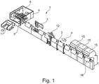
- the saddle stitcher 1 according to Fig. 1 in the present exemplary embodiment comprises three feeders 15, each of which transfers a sheet 16 to a collecting chain 2.
- the saddle stitcher 1 for printed products has at least the assemblies of saddle chain 2, stapling machine 3, control device 4, ejector 5 and delivery 6.
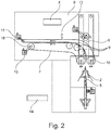
- the delivery 6 has at least one lower conveyor belt 7 and one upper conveyor belt 8 as well as at least one deflection roller 9 for the lower conveyor belt 7, wherein in Fig. 2 three deflection rollers 9 are shown as examples.
- the lower conveyor belt 7 has a controllable self-drive 10 and the upper conveyor belt 8 has a controllable self-drive 11.
- the control device 4 can control the self-drives 10, 11 separately.
- a thickness gauge 12 ( Fig. 1 ) is arranged in the product flow in front of the stapling machine 3, which transmits measurement data to the control device 4 in the usual way.
- Fig. 2 shows a schematic side view of the collection chain 2, the ejector 5 and the delivery 6.
- the delivery 6 has at least a lower conveyor belt 7 and an upper conveyor belt 8 and at least one deflection roller 9 for the lower conveyor belt 7, wherein in Fig. 2 three deflection rollers 9 are shown as examples.
- the delivery 6 has other assemblies known from the prior art, such as infeed rollers 18 and drive rollers 19.
- the lower conveyor belt 7 has a controllable self-drive 10 and the upper conveyor belt 8 has a controllable self-drive 11.
- the gap between the infeed rollers 18 can be dependent, for example, on the product thickness be changeable.
- the control device 4 controls the self-propulsion 10, 11 separately.
- the control device 4 is a control device customary for this purpose and has at least one conventional microprocessor, which makes it possible to process, in particular, different measurement data using software that is customary in this regard and thus to implement a control of controllable electrical components, such as a controllable electromotive self-drive 10, 11, which is customary in the manner.
- the control device 4 uses data which contain order data from the MIS 14 or from a company-specific order data system, for example the format data of the individual folded sheets, format data of the brochure, such as the cut width and length, and many other data which are required in order to obtain one To be able to realize an order for a printed product.
- the control device 4 can also, or alternatively, access data which are derived from measurement data of the current product process, such as from the thickness measuring device 12 ( Fig. 1 ) transmitted, generated precisely to the clock.
- the control device 4 can also or alternatively on torque measurement data of the self-propulsion 10; 11 for controlling the speed of the conveyor belts 7; 8 fall back and take this into account.
- the controllable self-drives 10, 11 each have at least one servo motor with a conventional control. These own drives 10, 11 drive the drive roller 19 variably in the usual manner.
Landscapes
- Engineering & Computer Science (AREA)
- Mechanical Engineering (AREA)
- Textile Engineering (AREA)
- Delivering By Means Of Belts And Rollers (AREA)
- Folding Of Thin Sheet-Like Materials, Special Discharging Devices, And Others (AREA)
- Portable Nailing Machines And Staplers (AREA)
Abstract
Description
- Die Erfindung betrifft einen Sammelhefter für Druckprodukte, welcher zumindest die Baugruppen Sammelkette, Heftmaschine, Steuereinrichtung, Auswerfer und Auslage besitzt, wobei die Auslage zumindest ein unteres Transportband und ein oberes Transportband sowie zumindest eine Umlenkrolle für das untere Transportband aufweist und diese zumindest eine Umlenkrolle in einem Radius angeordnet ist.
- Beim Digitaldruck kann jede Broschüre eine unterschiedliche Anzahl von Bogen aufweisen und somit jede Broschüre verschieden dick sein. Es ist auch ein kombiniertes System möglich, d.h. ein Teil der Broschüre kann aus traditionell gedruckten Bogenteilen, wie Tiefdruck, Offsetdruck etc., und ein weiterer Teil kann aus dem Digitaldruck stammen.
- Mit dem Thema "Industrie 4.0" sind in der Druckindustrie die Begriffe wie z.B. "Print_4.0" oder "Web to Print" verbunden, das bedeutet für die Druckmaschinen, dass auch Auflagengrössen = 1 verarbeitet werden müssen. Damit Druckmaschinen diese Anforderungen erfüllen können ist es insbesondere nötig:
- dass eine Kommunikation zu übergeordneten Systeme besteht, welche die nötigen Daten zur Verfügung stellen, und
- dass die Maschinen so konstruiert sind, dass die nötigen Einstellungen On-the-Fly und für jeden Produktionstakt gemacht werden können.
- Die zusammengestellten Broschüren, bestehend aus übereinander gelegten, gefalzten Bogenteilen, welche mit der Sammelkette in die Heftstation transportiert werden, wo sie im Falz geheftet werden.
-
- Druckprodukt:
- Fertiges Druckerzeugnis bestehend aus mindestens einem oder mehreren Bogenteilen (Zeitung, Heft, Magazin, Katalog).
- Heftmaschine:
- Heftet eine Broschüre, welche aus einem oder mehreren Bogen besteht, mittels einer Heftklammer.
- Bogen:
- Beidseitig bedrucktes Papier.
- Bogenteile:
- Mehrere Bögen (meist unterschiedlich bedruckt).
- Sammelkette:
- Horizontale Stetigfördereinheit für Bogenteile.
- Digitaldruck:
- Bogen werden direkt im Produktionsprozess bedruckt und zu einer Broschüre zusammengestellt, jede Broschüre kann eine unterschiedliche Anzahl von Bogen beinhalten und so die Dicke der Broschüre beeinflussen.
- Dickenvariabel:
- Die Dicke der Druckprodukte, welche taktweise verarbeitet werden, ist variabel; d. h. diese können eine unterschiedliche Dicke besitzen.
- Schneideinrichtung:
- Schneidsystem, welches über ein Vordermesser und zwei Seitenmesser verfügt und den Schnittprozess bestehend aus Frontschnitt und Kopf/Fussschnitt als Folgeschnitt ausführt.
- Produktzuführung:
- Mechanische Einrichtung zum Transportieren eines Druckproduktes, von der Auslage der Heftstation bis zur Schneideinrichtung.
- Sammelhefter:
- In einem Sammelhefter werden, meist mehrere Bogen auf einer Transportkette gesammelt, in der Heftstation geheftet und in der Schneideinrichtung auf drei Seiten geschnitten.
- Schneidapparat:
- Schneidsystem, welches über ein Vordermesser und zwei Seitenmesser verfügt und den Schnittprozess bestehend aus Frontschnitt und Kopf-Fussschnitt als Folgeschnitt ausführt.
- Sammelkette:
- Die Sammelkette besitzt eine Führungseinrichtung, deren oberer Abschnitt schneidenförmig ausgebildet ist und deren Gratlinie die Transport- und Heftlinie festlegt, und eine im Wesentlichen dachförmige Auflage, auf der die Bogenteile rittlings transportiert werden.
- Auslage:
- Maschinenkomponente, welche die Druckprodukte nach der Heftstation mit der Heftmaschine, in die Zuführung zum Schneidapparat transportiert. In der Auslage findet ein Transport-Richtungswechsel um 90 Grad statt, in Abhängigkeit des Standortes des Schneidapparates, nach vorn oder hinten.
- Auswurfphase, Auswerfen:
- Mittels einer Vorrichtung, genannt Auswerfer, wird das Druckprodukt soweit von der Sammelkette angehoben bis es von den Transportbändern in der Auslage erfasst und in derselben weitertransportiert wird.
- On-the-fly:
- Änderungen, z.B. von Einstellungen, Positionen von Vorrichtungen etc., während des Betriebes möglich.
- MIS
- Mangement-Information-System, Jobmanagementsystem.
- Aus der
EP1593526 A1 ist ein Sammelhefter für Broschüren mit einer Heftmaschine, einer betriebsmäßig schrittweise mit den Broschüren beschickten Ausgabestation, einer eine Schnittebene definierenden Vorderschnittmesseranordnung zum Beschnitt der Broschüren entlang einer jeweiligen Soll-Schnittlinie und mit Transportmittelkomponenten, welche die Broschüren betriebsmässig von der Ausgabestation zur Vorderschnittmesseranordnung transportieren bekannt. Die Auswerfer-Vorrichtung wird dabei formatunabhängig, in Bezug auf Transportmittelkomponenten und Transportvorrichtung der Broschüre im Bereich der Heftmaschine, angesteuert. Mit diesem Sammelhefter ist es nicht möglich unterschiedliche Druckprodukte beim Digitaldruck, d.h. insbesondere aufeinanderfolgende Druckprodukte mit unterschiedlichen Dicken und Formaten - ohne Umrüsten - zu verarbeiten, so dass taktgenau und On-the-fly Verarbeitung nicht ermöglicht ist. - Typischerweise wird bisher der Transport mittels Transportbändern (oben und unten) gewährleistet, welche von der Heftstation angetrieben sind. Unterschiedliche Geschwindigkeiten der Transportbänder werden mittels Variator bewerkstelligt. Dieser kann von Hand, mittels Hebel, oder motorisch verstellt werden.
- Die Probleme dieser technischen Lösung sind:
- Nicht exakt zu reproduzierende Einstellungen und funktionsbedingt nötige Eingriffe des Benutzers,
- Die Geschwindigkeit ist während des gesamten Transportwegs konstant, was oft zu Transportspuren auf der Oberfläche des Druckproduktes oder zur Deformierung des Broschüren-Rücken führen kann,
- Durch die mechanische Kopplung der Transportbänder an die Heftstation (dreht die Heftstation drehen auch die Transportbänder) ist eine Korrektur der Position der Druckprodukte (Abstand zum Einlauf des Schneidapparats) nicht möglich, und
- Eine taktgenaue Anpassung ist nicht möglich.
- Aufgabe der Erfindung ist es, einen Sammelhefter für Druckprodukte bereit zu stellen, welcher die Nachteile des Standes der Technik überwindet und in der Lage ist, von Takt zu Takt variierende Produktdicken zu verarbeiten, wobei diese Einstellung auf die Dickenvarianz während des Betriebes und zwischen zwei Heftvorgängen dynamisch erfolgen kann. Es soll außerdem wirksam verhindert werden, dass das Druckprodukt in der Auslage, verursacht durch eine unterschiedliche Bandgeschwindigkeit, beschädigt wird. Es soll eine Steuerung der jeweiligen Geschwindigkeit des unteren und/oder oberen Transportbandes taktgenau und On-the-fly ermöglicht sein. Druckprodukte mit unterschiedlichen Dicken und/oder mit unterschiedlichen Formaten sollen sicher und schonend transportiert werden.
- Die Aufgabe der Erfindung wird durch einen Sammelhefter für Druckprodukte mit den Merkmalen gemäß Anspruch 1 gelöst.
- Erfindungswesentlich ist, dass das untere Transportband 7 einen ansteuerbaren Eigenantrieb 10 und das obere Transportband 8 einen ansteuerbaren Eigenantrieb 11 besitzt und die Steuereinrichtung 4 zumindest die Eigenantriebe 10, 11 gesondert ansteuert, wobei die taktgenaue Steuerung primär auf die Dicke und das Format des jeweiligen Druckprodukts im Produktfluss abstimmbar ist.
- Die Steuereinrichtung 4 ist eine für diesen Verwendungszweck übliche Steuereinrichtung und besitzt zumindest einen üblichen Mikroprozessor, welcher es unter Verwendung einer diesbezüglich üblichen Software ermöglich, insbesondere unterschiedliche Messdaten zu verarbeiten und somit eine in Art und Weise üblichen Steuerung von ansteuerbaren elektrischen Bauteilen, wie einen ansteuerbaren elektromotorischen Antrieb, wie die Eigenantriebe 10, 11 zu realisieren.
- Durch das diesbezügliche Verzögern und/oder Beschleunigen der Transportbänder 7, 8 im Vergleich zu der Heftstation / Schnitttransport wird die synchronisierte Übergabe sichergestellt. Die Steuereinrichtung 4 kann auf Daten zurückgreifen, welche Auftragsdaten vom MIS oder von einem firmeneigenen Auftragsdaten-System beinhalten, z.B. die Formatdaten der einzelnen Falzbogen, Formatdaten der Broschüre, wie geschnittene Breite und Länge, und viele weitere Daten, die benötigt werden, um einen Auftrag für ein Druckprodukt realisieren zu können. Diese Daten können auf einem internationalen Standard basieren, beispielsweise dem CIP 4.
- Die Steuereinrichtung 4 kann außerdem oder alternativ auf Daten zurückgreifen, welche aus Messdaten des aktuellen Produktprozesses taktgenau generiert worden sind. Dabei kann die Steuerung Daten generieren, wie z.B. aus den Daten der einzelnen Falzbogen und/oder der Broschürendicke. Weiter erkennt die Steuerung auch Maschinendaten, wie die Geschwindigkeit der Maschine, Produktionsstati etc.. Anhand dieser Werte berechnet die Software der Steuereinrichtung 4 insbesondere die Geschwindigkeiten der Transportbänder 7, 8.
- Es können durch den erfindungsgemäßen Sammelhefter von Druckprodukt zu Druckprodukt (Takt zu Takt) variierende Produktdicken (dickenvariabel) verarbeitet werden, eine Anforderung, welche durch den Digitaldruck (jedes Druckprodukt ein Unikat) gestellt wird.
- Die vorliegende Erfindung befasst sich insbesondere mit der Steuerung der Geschwindigkeit des unteren Transportbandes 7 und/oder des oberen Transportbandes 8, welche die Broschüre durch die Auslage transportieren. Die Broschüre wird mit zumindest einer Umlenkrolle 9, welche in einem Radius angeordnet ist, von der vertikalen Achse in die horizontale Achse bewegt. Wenn sich die Broschüre im Bereich des Radius befindet, kann die Oberbandgeschwindigkeit, beispielsweise in Abhängigkeit der Produktdicke, erhöht und/oder verringert werden.
- Befindet sich die Broschüre ausserhalb des Radius-Bereiches der zumindest einen Umlenkrolle 9, welcher anhand der Formatgrösse, berechnet werden kann, kann wieder Gleichlauf zwischen dem unteren Transportband 7 und dem oberen Transportband 8 herrschen. Der Bewegungsablauf ist von verschiedenen Faktoren, wie beispielsweise Geschwindigkeit der Sammelkette 2, Dicke der Broschüre und Format der Broschüre, abhängig.
- Durch die erfindungsgemäße technische Lösung ist ermöglicht, dass die Übergabe der Broschüre vom Auswerfer 5 in die Auslage 6 sicher erfolgen kann, wobei eine Anpassung der Bandgeschwindigkeit an die Auswerfer-Geschwindigkeit ermöglicht ist. Es ist weiterhin ermöglicht, dass im Zusammenhang mit dem Verlassen der Auslage durch die Broschüre eine Anpassung der Bandgeschwindigkeit erfolgen kann, um den Übergang in die Zuführung der Schneideinrichtung zu optimieren.
- Weitere Vorteile der Erfindung:
- Mit den Eigenantrieben 10, 11 (Servomotoren) ist On-the-fly für jedes Druckprodukt möglich.
- Dynamisch regulierbare Oberband- und Unterband-Geschwindigkeit.
- Technisch einfache Lösung, da keine zusätzlichen Vorrichtungen, wie z.B. Variator, nötig sind.
- Master-Slave Kräfteausgleich ermöglicht, damit beide Motoren der Eigenantriebe 10, 11 gleich optimal belastet werden können.
- Geschwindigkeitsausgleich zwischen dem unteren Transportband 7 und dem oberen Transportband 8 bei variablen Produktdicken (da die Innenseite einen anderen Weg zurücklegen muss wie die Aussenseite (produktdickenabhängig).
- Unabhängig von Sammelkettengeschwindigkeit, resp. von der Einlaufgeschwindigkeit des Schneidapparates 17.
- Über die ganze Transportdistanz sind Geschwindigkeitsänderungen möglich.
- Während des Betriebes können das untere Transportband 7 und/oder das obere Transportband 8, insbesondere anhand von Formatdaten, Broschürendicke und Maschinengeschwindigkeit, gemäss nachfolgender Beschreibung:
a), b), c) und d) betrieben werden. -
- 1. Produktdicke bestimmt Geschwindigkeitsfaktor zwischen dem unteren Transportband 7 und dem oberen Transportband 8.
- 2. Während konstanter Produktionsgeschwindigkeit wird das Drehmoment aller Antriebe erfasst.
- 3. Bei Abweichung der Drehmomente vom zu erwartenden Wert wird der Geschwindigkeitsfaktor zwischen dem unteren Transportband 7 und dem oberen Transportband 8 entsprechend angepasst.
-
- 1. Bei einem Stopp des Sammelhefters 1 kann es vorkommen, dass kurz vor Stillstand die Auswurfbewegung gestartet wird und somit ein Druckprodukt in die stillstehenden, oder beinahe stillstehenden Transportbänder 7, 8 transportiert wird.
- 2. Um sicherzustellen, dass das Druckprodukt während Stillstand des Sammelhefters 1 korrekt platziert bleibt, drehen die Transportbänder 7, 8 noch eine bestimmte Distanz weiter.
- 3. Diese Distanz wird beim Wiederanlauf kompensiert.
-
- 1. Bei normalen Geschwindigkeiten drehen die Transportbänder 7, 8 synchron zum Produktetakt, da die Druckprodukte synchron in die Auslage 6 befördert werden.
- 2. Mittels der optischen Kontrolleinrichtung 13, wie Sensoren, wie Fotozellen, Kamerasysteme oder ähnliche, wird die Position in der Auslage erfasst.
- 3. Allfällige Abweichung zur Sollposition (Abweichung wegen Schlupf, mechanische Verstellung, etc.) wird im Lauf kompensiert.
-
- 1. Im Gegensatz zu normalen Geschwindigkeiten gibt es Geschwindigkeitsbereiche in denen die Druckprodukte nicht synchron in die Auslage befördert werden.
- 2. Die berechnete Abweichung kann mittels Positionsausgleich der Transportbänder 7, 8 kompensiert werden. Wie z.B. die Funktion "Hinkebetrieb", welche bei mechanischen Lösungen bekannt ist.
- 3. Mittels der optischen Kontrolleinrichtung 13, wie Sensoren, wie Fotozellen, Kamerasysteme oder ähnliche, wird die Position in der Auslage erfasst.
- 4. Allfällige Abweichung zur Sollposition (Abweichung wegen nicht genauer Berechnung, Schlupf, mechanische Verstellung, etc.) wird im Lauf kompensiert.
- Die abhängigen Ansprüche 2 bis 7 enthalten vorteilhafte Ausgestaltungen der Erfindung ohne diese damit zu begrenzen.
- Bevorzugt ist, dass ein Dickenmessgerät 12 im Produktfluss vor der Heftmaschine 3 angeordnet ist.
- Bevorzugt ist, dass im horizontalen Bereich des unteren Transportbandes 7, bevorzugt unmittelbar am Übergang vom Radius zum horizontalen Bereich, eine optische Kontrolleinrichtung 13, welche ein Messsignal erzeugt, welches zur Steuereinrichtung 4 übertragen wird, angeordnet ist. Diese optische Kontrolleinrichtung 13 kann eine diesbezüglich übliche Messeinrichtung, beispielsweise ein optischer Sensor, eine Photozelle oder ein Kamerasystem, sein. Deformationen der Broschüre können somit detektiert werden und dementsprechend die Bandgeschwindigkeiten des unteren und/oder oberen Transportbandes angepasst werden.
- Bevorzugt ist, dass die Steuereinrichtung 4 Steuerdaten generiert oder besitzt, welche zumindest aus Daten ein MIS 14 und/oder des Dickenmessgeräts 12 und/oder der Kontrolleinrichtung 13 ermittelt werden. Die Produktdicke des zu heftenden Druckproduktes kann zusätzlich mit einer Produktdickenmessung während des Betriebes ermittelt werden, um eventuell Abweichungen von den Soll-Daten aus dem MIS 14 (Jobmanagementsystem) zu ermitteln, um nachjustieren zu können.
- Bevorzugt ist, dass die Steuereinrichtung 4, welche zumindest einen Mikroprozessor besitzt, Drehmomentmessdaten der Eigenantriebe 10; 11 zur Steuerung der Geschwindigkeit der Transportbänder 7; 8 berücksichtigt. Die Messung des Drehmoments in den einzelnen Eigenantrieben 10; 11 ermöglicht eine Korrektur der Geschwindigkeit der Transportbänder 7; 8. Die Differenz, insbe-sondere kombiniert mit der Information der Produktdicke, wird verwendet, um die Geschwindigkeit der Transportbänder zu beeinflussen. Dadurch wird sichergestellt, dass die Kräfte auf Oberseite und Unterseite des Druckproduktes über den ganzen Transportweg ausgeglichen sind.
- Bevorzugt ist, dass die Eigenantriebe 10, 11 zumindest jeweils einen Servomotor mit Regelung oder einen Asynchronmotor mit Regelung besitzen.
- Die Merkmale der Erfindung sind nachfolgend unter Bezugnahme auf die beigefügten Zeichnungen dargelegt, wobei diese die Erfindung damit nicht beschränken. In den Zeichnungen zeigt:
- Fig. 1:
- eine vereinfachte Darstellung eines Sammelhefters, und
- Fig. 2:
- eine schematische Seitenansicht der Sammelkette, des Auswerfers und der Auslage.
- Der Sammelhefter 1 gemäß
Fig. 1 umfasst im vorliegenden Ausführungsbeispiel drei Anleger 15, die jeweils einen Bogen 16 an eine Sammelkette 2 übergeben. Die auf diese Weise ab- und übereinander gelegten Bogen 16 bilden gemeinsam die Bogenteile, welche in einer Transportrichtung gemäß dem Pfeil P entlang transportiert werden, die sich entlang der Anleger 15 und über eine Heftmaschine 3 hinaus bis zu einer Auslage 6 erstreckt. - In Transportrichtung nach der Heftmaschine 3 liegt eine Broschüre vor, welche aus einem oder mehreren Bogen 16 besteht. Von der Sammelkette 2 wird die Broschüre nachfolgend durch einen Auswerfer 5 in üblicher Art und Weise angehoben und der Auslage 6 übergeben. Von der Auslage 6 wird die Broschüre an einen Schneidapparat 17 übergeben.
- Der Sammelhefter 1 für Druckprodukte besitzt zumindest die Baugruppen Sammelkette 2, Heftmaschine 3, Steuereinrichtung 4, Auswerfer 5 und Auslage 6.
- Die Auslage 6 weist zumindest ein unteres Transportband 7 und ein oberes Transportband 8 sowie zumindest eine Umlenkrolle 9 für das untere Transportband 7 auf, wobei in
Fig. 2 beispielhaft drei Umlenkrollen 9 dargestellt sind. Das untere Transportband 7 besitzt einen ansteuerbaren Eigenantrieb 10 und das obere Transportband 8 besitzt einen ansteuerbaren Eigenantrieb 11. Die Steuereinrichtung 4 kann die Eigenantriebe 10, 11 gesondert ansteuern. Eine Dickenmessgerät 12 (Fig. 1 ) ist im Produktfluss vor der Heftmaschine 3 angeordnet, welches in üblicher Art und Weise Messdaten an die Steuervorrichtung 4 übermittelt. -
Fig. 2 zeigt eine schematische Seitenansicht der Sammelkette 2, des Auswerfers 5 und der Auslage 6. Die Auslage 6 weist zumindest ein unteres Transportband 7 und ein oberes Transportband 8 sowie zumindest eine Umlenkrolle 9 für das untere Transportband 7 auf, wobei inFig. 2 beispielhaft drei Umlenkrollen 9 dargestellt sind. Die Auslage 6 besitzt weitere aus dem Stand der Technik bekannte Baugruppen, wie beispielsweise Einlaufrollen 18 und Antriebsrollen 19. Das untere Transportband 7 besitzt einen ansteuerbaren Eigenantrieb 10 und das obere Transportband 8 besitzt einen ansteuerbaren Eigenantrieb 11. Der Spalt zwischen den Einlaufrollen 18 kann beispielsweise produktdickenabhängig veränderbar sein. - Im horizontalen Bereich des unteren Transportbandes 7, unmittelbar am Übergang vom Radius zum horizontalen Bereich, ist eine optische Kontrolleinrichtung 13, welche ein Messsignal erzeugt, welches zur Steuereinrichtung 4 übertragen wird, angeordnet.
- Die Steuereinrichtung 4 steuert die Eigenantriebe 10, 11 gesondert an. Die Steuereinrichtung 4 ist eine für diesen Verwendungszweck übliche Steuereinrichtung und besitzt zumindest einen üblichen Mikroprozessor, welcher es unter Verwendung einer diesbezüglich üblichen Software ermöglich, insbesondere unterschiedliche Messdaten zu verarbeiten und somit eine in Art und Weise üblichen Steuerung von ansteuerbaren elektrischen Bauteilen, wie einen ansteuerbaren elektromotorischen Eigenantrieb 10, 11 zu realisieren. Die Steuereinrichtung 4 greift auf Daten zurück, welche Auftragsdaten vom MIS 14 oder von einem firmeneigenen Auftragsdaten-System beinhalten, z.B. die Formatdaten der einzelnen Falzbogen, Formatdaten der Broschüre, wie geschnittene Breite und Länge, und viele weitere Daten, die benötigt werden, um einen Auftrag für ein Druckprodukt realisieren zu können.
- Die Steuereinrichtung 4 kann außerdem oder alternativ auf Daten zurückgreifen, welche aus Messdaten des aktuellen Produktprozesses, wie vom Dickenmessgerät 12 (
Fig. 1 ) übermittelt, taktgenau generiert werden. Die Steuereinrichtung 4 kann außerdem oder alternativ auf Drehmomentmessdaten der Eigenantriebe 10; 11 zur Steuerung der Geschwindigkeit der Transportbänder 7; 8 zurückgreifen und diese berücksichtigen. Die steuerbaren Eigenantriebe 10, 11 besitzen zumindest jeweils einen Servomotor mit einer üblichen Regelung. Diese Eigenantriebe 10, 11 treiben in üblicher Art und Weise die Antriebsrolle 19 variabel an.
Claims (8)
- Sammelhefter (1) für Druckprodukte, welcher zumindest die Baugruppen Sammelkette (2), Heftmaschine (3), Steuereinrichtung (4), Auswerfer (5) und Auslage (6) besitzt, wobei die Auslage (6) zumindest ein unteres Transportband (7) und ein oberes Transportband (8) sowie zumindest eine Umlenkrolle (9) für das untere Transportband (7) aufweist, wobei die zumindest eine Umlenkrolle (9) in einem Radius angeordnet ist, dadurch gekennzeichnet, dass das untere Transportband (7) einen ansteuerbaren Eigenantrieb (10) und das obere Transportband (8) einen ansteuerbaren Eigenantrieb (11) besitzt und die Steuereinrichtung (4) zumindest die Eigenantriebe (10, 11) gesondert ansteuert, wobei die taktgenaue Steuerung primär auf die Dicke und das Format des jeweiligen Druckprodukts im Produktfluss abstimmbar ist.
- Sammelhefter nach Anspruch 1, dadurch gekennzeichnet, dass ein Dickenmessgerät (12) im Produktfluss vorder Heftmaschine (3) angeordnet ist.
- Sammelhefter nach Anspruch 1 oder 2, dadurch gekennzeichnet, dass im horizontalen Bereich des unteren Transportbandes (7), bevorzugt unmittelbar am Übergang vom Radius zum horizontalen Bereich, eine optische Kontrolleinrichtung (13), welche ein Messsignal erzeugt, welches zur Steuereinrichtung (4) übertragen wird, angeordnet ist.
- Sammelhefter nach einem der Ansprüche 1 bis 3, dadurch gekennzeichnet, dass die Steuereinrichtung (4) Steuerdaten generiert oder besitzt, welche zumindest aus Daten einer MIS (14) und/oder des Dickenmessgeräts (12) und/oder der Kontrolleinrichtung (13) ermittelt werden.
- Sammelhefter nach einem der Ansprüche 1 bis 4, dadurch gekennzeichnet, dass die Steuereinrichtung (4), welche zumindest einen Mikroprozessor besitzt, Drehmomentmessdaten der Eigenantriebe (10; 11) zur Steuerung der Geschwindigkeit der Transportbänder (7; 8) berücksichtigt.
- Sammelhefter nach einem der Ansprüche 1 bis 5, dadurch gekennzeichnet, dass die Eigenantriebe (10, 11) zumindest jeweils einen Servomotor mit Regelung oder einen Asynchronmotor mit Regelung besitzen.
- Sammelhefter nach einem der Ansprüche 1 bis 6, dadurch gekennzeichnet, dass die Steuereinrichtung (4) Drehmomentmessdaten von zumindest zwei Umlenkrollen (9) zur Steuerung der Geschwindigkeit der Transportbänder (7; 8) berücksichtigt.
- Verwendung des Sammelhefters (1) für Druckprodukte nach zumindest einem der Ansprüche 1 bis 7 für den Digitaldruck.
Applications Claiming Priority (1)
| Application Number | Priority Date | Filing Date | Title |
|---|---|---|---|
| CH9202018 | 2018-07-25 |
Publications (2)
| Publication Number | Publication Date |
|---|---|
| EP3599103A1 true EP3599103A1 (de) | 2020-01-29 |
| EP3599103B1 EP3599103B1 (de) | 2020-10-14 |
Family
ID=63077660
Family Applications (1)
| Application Number | Title | Priority Date | Filing Date |
|---|---|---|---|
| EP19186828.0A Active EP3599103B1 (de) | 2018-07-25 | 2019-07-17 | Sammelhefter für druckprodukte |
Country Status (4)
| Country | Link |
|---|---|
| US (1) | US11034535B2 (de) |
| EP (1) | EP3599103B1 (de) |
| JP (1) | JP7355540B2 (de) |
| CN (1) | CN110774793B (de) |
Citations (4)
| Publication number | Priority date | Publication date | Assignee | Title |
|---|---|---|---|---|
| US4482141A (en) * | 1982-09-22 | 1984-11-13 | Stobb, Inc. | Method and apparatus for conveying folded sheets using orbitally gripping and releasing clamp pads |
| WO2001034403A2 (en) * | 1999-11-11 | 2001-05-17 | Ibis Integrated Bindery Systems Ltd | Book bindery and trimming apparatus |
| EP1593526A2 (de) | 2004-05-04 | 2005-11-09 | Heidelberger Druckmaschinen Aktiengesellschaft | Sammelhefter für Broschuren |
| WO2008019101A2 (en) * | 2006-08-03 | 2008-02-14 | Goss International Americas, Inc. | Transport device including an actuating tape nip |
Family Cites Families (15)
| Publication number | Priority date | Publication date | Assignee | Title |
|---|---|---|---|---|
| US4518156A (en) * | 1982-09-22 | 1985-05-21 | Stobb, Inc. | Method for conveying folded sheets |
| US4499834A (en) * | 1982-12-10 | 1985-02-19 | Harris Graphics Corporation | Reject assembly for sheet material handling apparatus |
| JP2000072320A (ja) | 1998-09-02 | 2000-03-07 | Konica Corp | シート後処理装置及び画像形成装置 |
| GB9824162D0 (en) * | 1998-11-04 | 1998-12-30 | Rue De Int Ltd | Sheet transport system |
| JP2003305968A (ja) * | 2002-04-16 | 2003-10-28 | Dainippon Printing Co Ltd | 多種帳票対応の製本装置 |
| JP4052324B2 (ja) * | 2005-01-12 | 2008-02-27 | コニカミノルタビジネステクノロジーズ株式会社 | 用紙後処理装置および画像形成システム |
| ATE468950T1 (de) | 2006-03-09 | 2010-06-15 | Mueller Martini Holding Ag | Verfahren und vorrichtung zum selbsttätigen beschneiden von druckerzeugnissen |
| EP2457738B1 (de) * | 2008-04-30 | 2015-02-11 | Müller Martini Holding AG | Verfahren zum Klebebinden von Buchblocks mit Vorsatzbogen |
| EP2361785B1 (de) | 2010-02-18 | 2015-11-11 | Müller Martini Holding AG | Verfahren zum Heften von Druckprodukten mit einer Heftmaschine und Heftmaschine zum Durchführen des Verfahrens |
| JP5440417B2 (ja) * | 2010-06-25 | 2014-03-12 | コニカミノルタ株式会社 | リング製本装置及びこのリング製本装置を備えた画像形成システム |
| DE102012005462A1 (de) | 2012-03-20 | 2013-09-26 | Heidelberger Druckmaschinen Ag | Schneidevorrichtung |
| JP6196782B2 (ja) | 2013-02-14 | 2017-09-13 | 株式会社グラフィック | 中綴じ製本機 |
| JP2015120269A (ja) * | 2013-12-20 | 2015-07-02 | 大日本印刷株式会社 | 中綴製本装置、不良刷本束仕分け装置、不良刷本束仕分け方法 |
| JP5911612B2 (ja) | 2014-01-23 | 2016-04-27 | キヤノン株式会社 | シート処理装置及び画像形成装置 |
| DE102014009425A1 (de) * | 2014-06-25 | 2015-12-31 | Müller Martini Holding AG | Verfahren zur Optimierung der Dickeneinstellung eines Klebebinders |
-
2019
- 2019-07-17 EP EP19186828.0A patent/EP3599103B1/de active Active
- 2019-07-19 JP JP2019133205A patent/JP7355540B2/ja active Active
- 2019-07-22 US US16/517,687 patent/US11034535B2/en active Active
- 2019-07-25 CN CN201910675801.0A patent/CN110774793B/zh active Active
Patent Citations (4)
| Publication number | Priority date | Publication date | Assignee | Title |
|---|---|---|---|---|
| US4482141A (en) * | 1982-09-22 | 1984-11-13 | Stobb, Inc. | Method and apparatus for conveying folded sheets using orbitally gripping and releasing clamp pads |
| WO2001034403A2 (en) * | 1999-11-11 | 2001-05-17 | Ibis Integrated Bindery Systems Ltd | Book bindery and trimming apparatus |
| EP1593526A2 (de) | 2004-05-04 | 2005-11-09 | Heidelberger Druckmaschinen Aktiengesellschaft | Sammelhefter für Broschuren |
| WO2008019101A2 (en) * | 2006-08-03 | 2008-02-14 | Goss International Americas, Inc. | Transport device including an actuating tape nip |
Also Published As
| Publication number | Publication date |
|---|---|
| JP2020015316A (ja) | 2020-01-30 |
| US11034535B2 (en) | 2021-06-15 |
| EP3599103B1 (de) | 2020-10-14 |
| US20200031597A1 (en) | 2020-01-30 |
| CN110774793A (zh) | 2020-02-11 |
| JP7355540B2 (ja) | 2023-10-03 |
| CN110774793B (zh) | 2022-09-06 |
Similar Documents
| Publication | Publication Date | Title |
|---|---|---|
| EP1882566B1 (de) | Bogenstanz- und -prägemaschine mit Passerausrichtung und Verfahren zum Betreiben einer Bogenstanz- und -prägemaschine | |
| EP2411313B1 (de) | Verfahren zur korrektur einer schräglage eines aus einem falzwalzenspalt zweier falzwalzen eines längsfalzapparates austretenden produktes und längsfalzapparat | |
| EP2407402B1 (de) | Verfahren und Vorrichtung zum Positonieren von Bogen | |
| EP2098469B1 (de) | Verfahren zum Vermessen der Lage von Bogen und zur Ausrichtung von Bogen | |
| DE102011006905A1 (de) | Maschine zum Herstellen von Büchern, insbesondere Fotobüchern und/oder Bildbänden | |
| EP1832399B2 (de) | Verfahren und Vorrichtung zum selbsttätigen Beschneiden von Druckerzeugnissen | |
| DE4444755A1 (de) | Vorrichtung zum Fördern von Bogen im Anlegerbereich einer bogenverarbeitenden Maschine | |
| EP1281653A2 (de) | Vorrichtung zum rotativen Bearbeiten von blattförmigen Bedruckstoffen | |
| DE10103040B4 (de) | Verfahren zur Bildung einer Folge von unterlappten Bögen | |
| CH713149A1 (de) | Verfahren und Vorrichtung zum Transport dickenvariabler Druckprodukte. | |
| EP1762525B2 (de) | Einrichtung für das Zusammentragen bzw. Sammeln von Druckprodukten | |
| DE69107697T2 (de) | Regler zur automatischen Steuerung des Arbeitszyklusses eines Falzmessers. | |
| EP0047413B1 (de) | Verfahren und Vorrichtung zum Steuern der Ankunft einzeln vorgeschobener Bogen aus biegsamem Material | |
| EP2935060B1 (de) | Vorrichtung und verfahren zum drehen von flachen gütern | |
| EP3599103B1 (de) | Sammelhefter für druckprodukte | |
| EP2583924A2 (de) | Bogenbearbeitungsmaschine mit Bogenanleger mit Saugbandmodul | |
| DE102016008864A1 (de) | Maschine zur automatisierten Herstellung von Bucheinbanddecken | |
| CH712159A2 (de) | Verfahren und Vorrichtung für den Transport von dickenvariablen Druckprodukten. | |
| DE10028070B4 (de) | Vorrichtung zur formatabhängigen Lageerfassung der Bogenvorderkante im Anleger von bogenverarbeitenden Maschinen | |
| DE102007054938A1 (de) | Vorrichtung zur Bildung eines Schuppenstroms | |
| EP3599104A1 (de) | Anlage zum ausfördern von druckprodukten gleicher oder unterschiedlicher dicke und verfahren für deren übergabe an eine auslage | |
| EP2746204A2 (de) | Vorrichtung und Verfahren zum Drehen von flachen Gütern | |
| DE60100084T2 (de) | Vorrichtung zum Schneiden von einzelnen Bogen mit einer Changiereinrichtung zur Stellung der Lage der Bogen | |
| DE10146923A1 (de) | Vorrichtung zum rotativen Bearbeiten von blattförmigen Bedruckstoffen | |
| DE202009008741U1 (de) | Rillwerk zum Rillen von flachen Druckbogen oder Bahnen |
Legal Events
| Date | Code | Title | Description |
|---|---|---|---|
| PUAI | Public reference made under article 153(3) epc to a published international application that has entered the european phase |
Free format text: ORIGINAL CODE: 0009012 |
|
| STAA | Information on the status of an ep patent application or granted ep patent |
Free format text: STATUS: THE APPLICATION HAS BEEN PUBLISHED |
|
| AK | Designated contracting states |
Kind code of ref document: A1 Designated state(s): AL AT BE BG CH CY CZ DE DK EE ES FI FR GB GR HR HU IE IS IT LI LT LU LV MC MK MT NL NO PL PT RO RS SE SI SK SM TR |
|
| AX | Request for extension of the european patent |
Extension state: BA ME |
|
| STAA | Information on the status of an ep patent application or granted ep patent |
Free format text: STATUS: REQUEST FOR EXAMINATION WAS MADE |
|
| 17P | Request for examination filed |
Effective date: 20200409 |
|
| RBV | Designated contracting states (corrected) |
Designated state(s): AL AT BE BG CH CY CZ DE DK EE ES FI FR GB GR HR HU IE IS IT LI LT LU LV MC MK MT NL NO PL PT RO RS SE SI SK SM TR |
|
| GRAP | Despatch of communication of intention to grant a patent |
Free format text: ORIGINAL CODE: EPIDOSNIGR1 |
|
| STAA | Information on the status of an ep patent application or granted ep patent |
Free format text: STATUS: GRANT OF PATENT IS INTENDED |
|
| INTG | Intention to grant announced |
Effective date: 20200623 |
|
| GRAS | Grant fee paid |
Free format text: ORIGINAL CODE: EPIDOSNIGR3 |
|
| GRAA | (expected) grant |
Free format text: ORIGINAL CODE: 0009210 |
|
| STAA | Information on the status of an ep patent application or granted ep patent |
Free format text: STATUS: THE PATENT HAS BEEN GRANTED |
|
| AK | Designated contracting states |
Kind code of ref document: B1 Designated state(s): AL AT BE BG CH CY CZ DE DK EE ES FI FR GB GR HR HU IE IS IT LI LT LU LV MC MK MT NL NO PL PT RO RS SE SI SK SM TR |
|
| REG | Reference to a national code |
Ref country code: GB Ref legal event code: FG4D Free format text: NOT ENGLISH |
|
| REG | Reference to a national code |
Ref country code: AT Ref legal event code: REF Ref document number: 1323201 Country of ref document: AT Kind code of ref document: T Effective date: 20201015 Ref country code: CH Ref legal event code: EP |
|
| REG | Reference to a national code |
Ref country code: DE Ref legal event code: R096 Ref document number: 502019000296 Country of ref document: DE |
|
| REG | Reference to a national code |
Ref country code: IE Ref legal event code: FG4D Free format text: LANGUAGE OF EP DOCUMENT: GERMAN |
|
| REG | Reference to a national code |
Ref country code: NL Ref legal event code: MP Effective date: 20201014 |
|
| PG25 | Lapsed in a contracting state [announced via postgrant information from national office to epo] |
Ref country code: RS Free format text: LAPSE BECAUSE OF FAILURE TO SUBMIT A TRANSLATION OF THE DESCRIPTION OR TO PAY THE FEE WITHIN THE PRESCRIBED TIME-LIMIT Effective date: 20201014 Ref country code: PT Free format text: LAPSE BECAUSE OF FAILURE TO SUBMIT A TRANSLATION OF THE DESCRIPTION OR TO PAY THE FEE WITHIN THE PRESCRIBED TIME-LIMIT Effective date: 20210215 Ref country code: FI Free format text: LAPSE BECAUSE OF FAILURE TO SUBMIT A TRANSLATION OF THE DESCRIPTION OR TO PAY THE FEE WITHIN THE PRESCRIBED TIME-LIMIT Effective date: 20201014 Ref country code: NO Free format text: LAPSE BECAUSE OF FAILURE TO SUBMIT A TRANSLATION OF THE DESCRIPTION OR TO PAY THE FEE WITHIN THE PRESCRIBED TIME-LIMIT Effective date: 20210114 Ref country code: GR Free format text: LAPSE BECAUSE OF FAILURE TO SUBMIT A TRANSLATION OF THE DESCRIPTION OR TO PAY THE FEE WITHIN THE PRESCRIBED TIME-LIMIT Effective date: 20210115 |
|
| REG | Reference to a national code |
Ref country code: LT Ref legal event code: MG4D |
|
| PG25 | Lapsed in a contracting state [announced via postgrant information from national office to epo] |
Ref country code: ES Free format text: LAPSE BECAUSE OF FAILURE TO SUBMIT A TRANSLATION OF THE DESCRIPTION OR TO PAY THE FEE WITHIN THE PRESCRIBED TIME-LIMIT Effective date: 20201014 Ref country code: SE Free format text: LAPSE BECAUSE OF FAILURE TO SUBMIT A TRANSLATION OF THE DESCRIPTION OR TO PAY THE FEE WITHIN THE PRESCRIBED TIME-LIMIT Effective date: 20201014 Ref country code: PL Free format text: LAPSE BECAUSE OF FAILURE TO SUBMIT A TRANSLATION OF THE DESCRIPTION OR TO PAY THE FEE WITHIN THE PRESCRIBED TIME-LIMIT Effective date: 20201014 Ref country code: LV Free format text: LAPSE BECAUSE OF FAILURE TO SUBMIT A TRANSLATION OF THE DESCRIPTION OR TO PAY THE FEE WITHIN THE PRESCRIBED TIME-LIMIT Effective date: 20201014 Ref country code: IS Free format text: LAPSE BECAUSE OF FAILURE TO SUBMIT A TRANSLATION OF THE DESCRIPTION OR TO PAY THE FEE WITHIN THE PRESCRIBED TIME-LIMIT Effective date: 20210214 Ref country code: BG Free format text: LAPSE BECAUSE OF FAILURE TO SUBMIT A TRANSLATION OF THE DESCRIPTION OR TO PAY THE FEE WITHIN THE PRESCRIBED TIME-LIMIT Effective date: 20210114 |
|
| PG25 | Lapsed in a contracting state [announced via postgrant information from national office to epo] |
Ref country code: NL Free format text: LAPSE BECAUSE OF FAILURE TO SUBMIT A TRANSLATION OF THE DESCRIPTION OR TO PAY THE FEE WITHIN THE PRESCRIBED TIME-LIMIT Effective date: 20201014 Ref country code: HR Free format text: LAPSE BECAUSE OF FAILURE TO SUBMIT A TRANSLATION OF THE DESCRIPTION OR TO PAY THE FEE WITHIN THE PRESCRIBED TIME-LIMIT Effective date: 20201014 |
|
| REG | Reference to a national code |
Ref country code: DE Ref legal event code: R097 Ref document number: 502019000296 Country of ref document: DE |
|
| PG25 | Lapsed in a contracting state [announced via postgrant information from national office to epo] |
Ref country code: SK Free format text: LAPSE BECAUSE OF FAILURE TO SUBMIT A TRANSLATION OF THE DESCRIPTION OR TO PAY THE FEE WITHIN THE PRESCRIBED TIME-LIMIT Effective date: 20201014 Ref country code: SM Free format text: LAPSE BECAUSE OF FAILURE TO SUBMIT A TRANSLATION OF THE DESCRIPTION OR TO PAY THE FEE WITHIN THE PRESCRIBED TIME-LIMIT Effective date: 20201014 Ref country code: EE Free format text: LAPSE BECAUSE OF FAILURE TO SUBMIT A TRANSLATION OF THE DESCRIPTION OR TO PAY THE FEE WITHIN THE PRESCRIBED TIME-LIMIT Effective date: 20201014 Ref country code: CZ Free format text: LAPSE BECAUSE OF FAILURE TO SUBMIT A TRANSLATION OF THE DESCRIPTION OR TO PAY THE FEE WITHIN THE PRESCRIBED TIME-LIMIT Effective date: 20201014 Ref country code: RO Free format text: LAPSE BECAUSE OF FAILURE TO SUBMIT A TRANSLATION OF THE DESCRIPTION OR TO PAY THE FEE WITHIN THE PRESCRIBED TIME-LIMIT Effective date: 20201014 Ref country code: LT Free format text: LAPSE BECAUSE OF FAILURE TO SUBMIT A TRANSLATION OF THE DESCRIPTION OR TO PAY THE FEE WITHIN THE PRESCRIBED TIME-LIMIT Effective date: 20201014 |
|
| PLBE | No opposition filed within time limit |
Free format text: ORIGINAL CODE: 0009261 |
|
| STAA | Information on the status of an ep patent application or granted ep patent |
Free format text: STATUS: NO OPPOSITION FILED WITHIN TIME LIMIT |
|
| PG25 | Lapsed in a contracting state [announced via postgrant information from national office to epo] |
Ref country code: DK Free format text: LAPSE BECAUSE OF FAILURE TO SUBMIT A TRANSLATION OF THE DESCRIPTION OR TO PAY THE FEE WITHIN THE PRESCRIBED TIME-LIMIT Effective date: 20201014 |
|
| 26N | No opposition filed |
Effective date: 20210715 |
|
| PG25 | Lapsed in a contracting state [announced via postgrant information from national office to epo] |
Ref country code: IT Free format text: LAPSE BECAUSE OF FAILURE TO SUBMIT A TRANSLATION OF THE DESCRIPTION OR TO PAY THE FEE WITHIN THE PRESCRIBED TIME-LIMIT Effective date: 20201014 Ref country code: AL Free format text: LAPSE BECAUSE OF FAILURE TO SUBMIT A TRANSLATION OF THE DESCRIPTION OR TO PAY THE FEE WITHIN THE PRESCRIBED TIME-LIMIT Effective date: 20201014 |
|
| PG25 | Lapsed in a contracting state [announced via postgrant information from national office to epo] |
Ref country code: SI Free format text: LAPSE BECAUSE OF FAILURE TO SUBMIT A TRANSLATION OF THE DESCRIPTION OR TO PAY THE FEE WITHIN THE PRESCRIBED TIME-LIMIT Effective date: 20201014 |
|
| PG25 | Lapsed in a contracting state [announced via postgrant information from national office to epo] |
Ref country code: MC Free format text: LAPSE BECAUSE OF FAILURE TO SUBMIT A TRANSLATION OF THE DESCRIPTION OR TO PAY THE FEE WITHIN THE PRESCRIBED TIME-LIMIT Effective date: 20201014 |
|
| REG | Reference to a national code |
Ref country code: BE Ref legal event code: MM Effective date: 20210731 |
|
| PG25 | Lapsed in a contracting state [announced via postgrant information from national office to epo] |
Ref country code: IS Free format text: LAPSE BECAUSE OF FAILURE TO SUBMIT A TRANSLATION OF THE DESCRIPTION OR TO PAY THE FEE WITHIN THE PRESCRIBED TIME-LIMIT Effective date: 20210214 Ref country code: LU Free format text: LAPSE BECAUSE OF NON-PAYMENT OF DUE FEES Effective date: 20210717 Ref country code: FR Free format text: LAPSE BECAUSE OF NON-PAYMENT OF DUE FEES Effective date: 20210731 |
|
| PG25 | Lapsed in a contracting state [announced via postgrant information from national office to epo] |
Ref country code: IE Free format text: LAPSE BECAUSE OF NON-PAYMENT OF DUE FEES Effective date: 20210717 Ref country code: BE Free format text: LAPSE BECAUSE OF NON-PAYMENT OF DUE FEES Effective date: 20210731 |
|
| REG | Reference to a national code |
Ref country code: CH Ref legal event code: PL |
|
| PG25 | Lapsed in a contracting state [announced via postgrant information from national office to epo] |
Ref country code: LI Free format text: LAPSE BECAUSE OF NON-PAYMENT OF DUE FEES Effective date: 20220731 Ref country code: CH Free format text: LAPSE BECAUSE OF NON-PAYMENT OF DUE FEES Effective date: 20220731 |
|
| PG25 | Lapsed in a contracting state [announced via postgrant information from national office to epo] |
Ref country code: CY Free format text: LAPSE BECAUSE OF FAILURE TO SUBMIT A TRANSLATION OF THE DESCRIPTION OR TO PAY THE FEE WITHIN THE PRESCRIBED TIME-LIMIT Effective date: 20201014 |
|
| PG25 | Lapsed in a contracting state [announced via postgrant information from national office to epo] |
Ref country code: HU Free format text: LAPSE BECAUSE OF FAILURE TO SUBMIT A TRANSLATION OF THE DESCRIPTION OR TO PAY THE FEE WITHIN THE PRESCRIBED TIME-LIMIT; INVALID AB INITIO Effective date: 20190717 |
|
| GBPC | Gb: european patent ceased through non-payment of renewal fee |
Effective date: 20230717 |
|
| PG25 | Lapsed in a contracting state [announced via postgrant information from national office to epo] |
Ref country code: MK Free format text: LAPSE BECAUSE OF FAILURE TO SUBMIT A TRANSLATION OF THE DESCRIPTION OR TO PAY THE FEE WITHIN THE PRESCRIBED TIME-LIMIT Effective date: 20201014 Ref country code: GB Free format text: LAPSE BECAUSE OF NON-PAYMENT OF DUE FEES Effective date: 20230717 |
|
| PG25 | Lapsed in a contracting state [announced via postgrant information from national office to epo] |
Ref country code: TR Free format text: LAPSE BECAUSE OF FAILURE TO SUBMIT A TRANSLATION OF THE DESCRIPTION OR TO PAY THE FEE WITHIN THE PRESCRIBED TIME-LIMIT Effective date: 20201014 |
|
| PG25 | Lapsed in a contracting state [announced via postgrant information from national office to epo] |
Ref country code: MT Free format text: LAPSE BECAUSE OF FAILURE TO SUBMIT A TRANSLATION OF THE DESCRIPTION OR TO PAY THE FEE WITHIN THE PRESCRIBED TIME-LIMIT Effective date: 20201014 |
|
| REG | Reference to a national code |
Ref country code: AT Ref legal event code: MM01 Ref document number: 1323201 Country of ref document: AT Kind code of ref document: T Effective date: 20240717 |
|
| PGFP | Annual fee paid to national office [announced via postgrant information from national office to epo] |
Ref country code: DE Payment date: 20250730 Year of fee payment: 7 |
|
| PG25 | Lapsed in a contracting state [announced via postgrant information from national office to epo] |
Ref country code: AT Free format text: LAPSE BECAUSE OF NON-PAYMENT OF DUE FEES Effective date: 20240717 |
|
| PGFP | Annual fee paid to national office [announced via postgrant information from national office to epo] |
Ref country code: AT Payment date: 20260410 Year of fee payment: 5 |