EP3598565B1 - Batteriewärmeverwaltungintegrationssystem und betriebsverfahren dafür - Google Patents
Batteriewärmeverwaltungintegrationssystem und betriebsverfahren dafür Download PDFInfo
- Publication number
- EP3598565B1 EP3598565B1 EP18210503.1A EP18210503A EP3598565B1 EP 3598565 B1 EP3598565 B1 EP 3598565B1 EP 18210503 A EP18210503 A EP 18210503A EP 3598565 B1 EP3598565 B1 EP 3598565B1
- Authority
- EP
- European Patent Office
- Prior art keywords
- battery
- mode
- line
- cooler
- radiator
- Prior art date
- Legal status (The legal status is an assumption and is not a legal conclusion. Google has not performed a legal analysis and makes no representation as to the accuracy of the status listed.)
- Active
Links
Images





Classifications
-
- B—PERFORMING OPERATIONS; TRANSPORTING
- B60—VEHICLES IN GENERAL
- B60H—ARRANGEMENTS OF HEATING, COOLING, VENTILATING OR OTHER AIR-TREATING DEVICES SPECIALLY ADAPTED FOR PASSENGER OR GOODS SPACES OF VEHICLES
- B60H1/00—Heating, cooling or ventilating devices
- B60H1/00271—HVAC devices specially adapted for particular vehicle parts or components and being connected to the vehicle HVAC unit
- B60H1/00278—HVAC devices specially adapted for particular vehicle parts or components and being connected to the vehicle HVAC unit for the battery
-
- H—ELECTRICITY
- H01—ELECTRIC ELEMENTS
- H01M—PROCESSES OR MEANS, e.g. BATTERIES, FOR THE DIRECT CONVERSION OF CHEMICAL ENERGY INTO ELECTRICAL ENERGY
- H01M10/00—Secondary cells; Manufacture thereof
- H01M10/60—Heating or cooling; Temperature control
- H01M10/63—Control systems
- H01M10/635—Control systems based on ambient temperature
-
- B—PERFORMING OPERATIONS; TRANSPORTING
- B60—VEHICLES IN GENERAL
- B60H—ARRANGEMENTS OF HEATING, COOLING, VENTILATING OR OTHER AIR-TREATING DEVICES SPECIALLY ADAPTED FOR PASSENGER OR GOODS SPACES OF VEHICLES
- B60H1/00—Heating, cooling or ventilating devices
- B60H1/00642—Control systems or circuits; Control members or indication devices for heating, cooling or ventilating devices
- B60H1/00814—Control systems or circuits characterised by their output, for controlling particular components of the heating, cooling or ventilating installation
- B60H1/00878—Control systems or circuits characterised by their output, for controlling particular components of the heating, cooling or ventilating installation the components being temperature regulating devices
- B60H1/00885—Controlling the flow of heating or cooling liquid, e.g. valves or pumps
-
- B—PERFORMING OPERATIONS; TRANSPORTING
- B60—VEHICLES IN GENERAL
- B60L—PROPULSION OF ELECTRICALLY-PROPELLED VEHICLES; SUPPLYING ELECTRIC POWER FOR AUXILIARY EQUIPMENT OF ELECTRICALLY-PROPELLED VEHICLES; ELECTRODYNAMIC BRAKE SYSTEMS FOR VEHICLES IN GENERAL; MAGNETIC SUSPENSION OR LEVITATION FOR VEHICLES; MONITORING OPERATING VARIABLES OF ELECTRICALLY-PROPELLED VEHICLES; ELECTRIC SAFETY DEVICES FOR ELECTRICALLY-PROPELLED VEHICLES
- B60L50/00—Electric propulsion with power supplied within the vehicle
- B60L50/50—Electric propulsion with power supplied within the vehicle using propulsion power supplied by batteries or fuel cells
- B60L50/60—Electric propulsion with power supplied within the vehicle using propulsion power supplied by batteries or fuel cells using power supplied by batteries
- B60L50/64—Constructional details of batteries specially adapted for electric vehicles
-
- B—PERFORMING OPERATIONS; TRANSPORTING
- B60—VEHICLES IN GENERAL
- B60L—PROPULSION OF ELECTRICALLY-PROPELLED VEHICLES; SUPPLYING ELECTRIC POWER FOR AUXILIARY EQUIPMENT OF ELECTRICALLY-PROPELLED VEHICLES; ELECTRODYNAMIC BRAKE SYSTEMS FOR VEHICLES IN GENERAL; MAGNETIC SUSPENSION OR LEVITATION FOR VEHICLES; MONITORING OPERATING VARIABLES OF ELECTRICALLY-PROPELLED VEHICLES; ELECTRIC SAFETY DEVICES FOR ELECTRICALLY-PROPELLED VEHICLES
- B60L58/00—Methods or circuit arrangements for monitoring or controlling batteries or fuel cells, specially adapted for electric vehicles
- B60L58/10—Methods or circuit arrangements for monitoring or controlling batteries or fuel cells, specially adapted for electric vehicles for monitoring or controlling batteries
- B60L58/24—Methods or circuit arrangements for monitoring or controlling batteries or fuel cells, specially adapted for electric vehicles for monitoring or controlling batteries for controlling the temperature of batteries
- B60L58/26—Methods or circuit arrangements for monitoring or controlling batteries or fuel cells, specially adapted for electric vehicles for monitoring or controlling batteries for controlling the temperature of batteries by cooling
-
- B—PERFORMING OPERATIONS; TRANSPORTING
- B60—VEHICLES IN GENERAL
- B60L—PROPULSION OF ELECTRICALLY-PROPELLED VEHICLES; SUPPLYING ELECTRIC POWER FOR AUXILIARY EQUIPMENT OF ELECTRICALLY-PROPELLED VEHICLES; ELECTRODYNAMIC BRAKE SYSTEMS FOR VEHICLES IN GENERAL; MAGNETIC SUSPENSION OR LEVITATION FOR VEHICLES; MONITORING OPERATING VARIABLES OF ELECTRICALLY-PROPELLED VEHICLES; ELECTRIC SAFETY DEVICES FOR ELECTRICALLY-PROPELLED VEHICLES
- B60L58/00—Methods or circuit arrangements for monitoring or controlling batteries or fuel cells, specially adapted for electric vehicles
- B60L58/10—Methods or circuit arrangements for monitoring or controlling batteries or fuel cells, specially adapted for electric vehicles for monitoring or controlling batteries
- B60L58/24—Methods or circuit arrangements for monitoring or controlling batteries or fuel cells, specially adapted for electric vehicles for monitoring or controlling batteries for controlling the temperature of batteries
- B60L58/27—Methods or circuit arrangements for monitoring or controlling batteries or fuel cells, specially adapted for electric vehicles for monitoring or controlling batteries for controlling the temperature of batteries by heating
-
- H—ELECTRICITY
- H01—ELECTRIC ELEMENTS
- H01M—PROCESSES OR MEANS, e.g. BATTERIES, FOR THE DIRECT CONVERSION OF CHEMICAL ENERGY INTO ELECTRICAL ENERGY
- H01M10/00—Secondary cells; Manufacture thereof
- H01M10/60—Heating or cooling; Temperature control
- H01M10/61—Types of temperature control
- H01M10/613—Cooling or keeping cold
-
- H—ELECTRICITY
- H01—ELECTRIC ELEMENTS
- H01M—PROCESSES OR MEANS, e.g. BATTERIES, FOR THE DIRECT CONVERSION OF CHEMICAL ENERGY INTO ELECTRICAL ENERGY
- H01M10/00—Secondary cells; Manufacture thereof
- H01M10/60—Heating or cooling; Temperature control
- H01M10/61—Types of temperature control
- H01M10/615—Heating or keeping warm
-
- H—ELECTRICITY
- H01—ELECTRIC ELEMENTS
- H01M—PROCESSES OR MEANS, e.g. BATTERIES, FOR THE DIRECT CONVERSION OF CHEMICAL ENERGY INTO ELECTRICAL ENERGY
- H01M10/00—Secondary cells; Manufacture thereof
- H01M10/60—Heating or cooling; Temperature control
- H01M10/62—Heating or cooling; Temperature control specially adapted for specific applications
- H01M10/625—Vehicles
-
- H—ELECTRICITY
- H01—ELECTRIC ELEMENTS
- H01M—PROCESSES OR MEANS, e.g. BATTERIES, FOR THE DIRECT CONVERSION OF CHEMICAL ENERGY INTO ELECTRICAL ENERGY
- H01M10/00—Secondary cells; Manufacture thereof
- H01M10/60—Heating or cooling; Temperature control
- H01M10/63—Control systems
- H01M10/633—Control systems characterised by algorithms, flow charts, software details or the like
-
- H—ELECTRICITY
- H01—ELECTRIC ELEMENTS
- H01M—PROCESSES OR MEANS, e.g. BATTERIES, FOR THE DIRECT CONVERSION OF CHEMICAL ENERGY INTO ELECTRICAL ENERGY
- H01M10/00—Secondary cells; Manufacture thereof
- H01M10/60—Heating or cooling; Temperature control
- H01M10/65—Means for temperature control structurally associated with the cells
- H01M10/656—Means for temperature control structurally associated with the cells characterised by the type of heat-exchange fluid
- H01M10/6561—Gases
- H01M10/6563—Gases with forced flow, e.g. by blowers
-
- H—ELECTRICITY
- H01—ELECTRIC ELEMENTS
- H01M—PROCESSES OR MEANS, e.g. BATTERIES, FOR THE DIRECT CONVERSION OF CHEMICAL ENERGY INTO ELECTRICAL ENERGY
- H01M10/00—Secondary cells; Manufacture thereof
- H01M10/60—Heating or cooling; Temperature control
- H01M10/65—Means for temperature control structurally associated with the cells
- H01M10/656—Means for temperature control structurally associated with the cells characterised by the type of heat-exchange fluid
- H01M10/6567—Liquids
- H01M10/6568—Liquids characterised by flow circuits, e.g. loops, located externally to the cells or cell casings
-
- H—ELECTRICITY
- H01—ELECTRIC ELEMENTS
- H01M—PROCESSES OR MEANS, e.g. BATTERIES, FOR THE DIRECT CONVERSION OF CHEMICAL ENERGY INTO ELECTRICAL ENERGY
- H01M10/00—Secondary cells; Manufacture thereof
- H01M10/60—Heating or cooling; Temperature control
- H01M10/66—Heat-exchange relationships between the cells and other systems, e.g. central heating systems or fuel cells
- H01M10/663—Heat-exchange relationships between the cells and other systems, e.g. central heating systems or fuel cells the system being an air-conditioner or an engine
-
- B—PERFORMING OPERATIONS; TRANSPORTING
- B60—VEHICLES IN GENERAL
- B60L—PROPULSION OF ELECTRICALLY-PROPELLED VEHICLES; SUPPLYING ELECTRIC POWER FOR AUXILIARY EQUIPMENT OF ELECTRICALLY-PROPELLED VEHICLES; ELECTRODYNAMIC BRAKE SYSTEMS FOR VEHICLES IN GENERAL; MAGNETIC SUSPENSION OR LEVITATION FOR VEHICLES; MONITORING OPERATING VARIABLES OF ELECTRICALLY-PROPELLED VEHICLES; ELECTRIC SAFETY DEVICES FOR ELECTRICALLY-PROPELLED VEHICLES
- B60L2270/00—Problem solutions or means not otherwise provided for
- B60L2270/46—Heat pumps, e.g. for cabin heating
-
- B—PERFORMING OPERATIONS; TRANSPORTING
- B60—VEHICLES IN GENERAL
- B60Y—INDEXING SCHEME RELATING TO ASPECTS CROSS-CUTTING VEHICLE TECHNOLOGY
- B60Y2200/00—Type of vehicle
- B60Y2200/90—Vehicles comprising electric prime movers
- B60Y2200/91—Electric vehicles
-
- B—PERFORMING OPERATIONS; TRANSPORTING
- B60—VEHICLES IN GENERAL
- B60Y—INDEXING SCHEME RELATING TO ASPECTS CROSS-CUTTING VEHICLE TECHNOLOGY
- B60Y2400/00—Special features of vehicle units
- B60Y2400/30—Sensors
- B60Y2400/302—Temperature sensors
-
- H—ELECTRICITY
- H01—ELECTRIC ELEMENTS
- H01M—PROCESSES OR MEANS, e.g. BATTERIES, FOR THE DIRECT CONVERSION OF CHEMICAL ENERGY INTO ELECTRICAL ENERGY
- H01M2220/00—Batteries for particular applications
- H01M2220/10—Batteries in stationary systems, e.g. emergency power source in plant
-
- H—ELECTRICITY
- H01—ELECTRIC ELEMENTS
- H01M—PROCESSES OR MEANS, e.g. BATTERIES, FOR THE DIRECT CONVERSION OF CHEMICAL ENERGY INTO ELECTRICAL ENERGY
- H01M2220/00—Batteries for particular applications
- H01M2220/20—Batteries in motive systems, e.g. vehicle, ship, plane
-
- Y—GENERAL TAGGING OF NEW TECHNOLOGICAL DEVELOPMENTS; GENERAL TAGGING OF CROSS-SECTIONAL TECHNOLOGIES SPANNING OVER SEVERAL SECTIONS OF THE IPC; TECHNICAL SUBJECTS COVERED BY FORMER USPC CROSS-REFERENCE ART COLLECTIONS [XRACs] AND DIGESTS
- Y02—TECHNOLOGIES OR APPLICATIONS FOR MITIGATION OR ADAPTATION AGAINST CLIMATE CHANGE
- Y02E—REDUCTION OF GREENHOUSE GAS [GHG] EMISSIONS, RELATED TO ENERGY GENERATION, TRANSMISSION OR DISTRIBUTION
- Y02E60/00—Enabling technologies; Technologies with a potential or indirect contribution to GHG emissions mitigation
- Y02E60/10—Energy storage using batteries
-
- Y—GENERAL TAGGING OF NEW TECHNOLOGICAL DEVELOPMENTS; GENERAL TAGGING OF CROSS-SECTIONAL TECHNOLOGIES SPANNING OVER SEVERAL SECTIONS OF THE IPC; TECHNICAL SUBJECTS COVERED BY FORMER USPC CROSS-REFERENCE ART COLLECTIONS [XRACs] AND DIGESTS
- Y02—TECHNOLOGIES OR APPLICATIONS FOR MITIGATION OR ADAPTATION AGAINST CLIMATE CHANGE
- Y02T—CLIMATE CHANGE MITIGATION TECHNOLOGIES RELATED TO TRANSPORTATION
- Y02T10/00—Road transport of goods or passengers
- Y02T10/60—Other road transportation technologies with climate change mitigation effect
- Y02T10/70—Energy storage systems for electromobility, e.g. batteries
Definitions
- the present invention relates to a battery heat management integration system and an operation method thereof, that utilize the heat of the battery that has been previously cooled for the heating during colder temperatures.
- a battery applied to an eco-friendly vehicle maintains a target temperature (e.g., set about 20-30°C as the target temperature in a lithium-ion battery) that is independent of the surrounding environment, thus maintaining optimal performance and efficiency, and for this purpose, a battery heat management system is required.
- the eco-friendly vehicle includes an electric vehicle and a hybrid vehicle.
- the battery heat management system is classified into an air-cooling type cooling device in which a battery is cooled using indoor air within a vehicle or a water cooling type cooling device in which a battery is cooled using cooling water.
- the air cooling type cooling device type battery heat management system is applied to a small electric vehicle and a hybrid vehicle.
- the water cooling type cooling device type battery heat management system applied to a commercial electric vehicle is deformed into a chiller type battery heat management system that a water cooling type cooling device and a roof-on air conditioner are bundled together based on whether a high-voltage battery that supplies power to an electric motor (i.e., a driving motor) is applied, thus enhancing battery cooling effect.
- the chiller type battery heat management system converts the radiator mode for circulating the cooling water by the radiator of the engine cooling system and the chiller mode (or the air conditioner mode) for operating the roof-on air conditioner into an ambient temperature condition to perform cooling.
- the chiller type battery heat management system is suitable for a commercial electric vehicle such as a bus since the water cooling type cooling device and the roof-on air conditioner independently configured on the roof are connected to the battery.
- this type of system is advantageously suitable for the environment in which the battery usage capacity and time of the high-voltage battery for supplying power to the electric motor (i.e., the driving motor) should be considered.
- the chiller type battery heat management system mounts the water cooling type cooling device and the roof-on air conditioner on the roof as independent parts, respectively, thus becoming disadvantageous in terms of a package by occupying a substantial amount of space on the roof due to redundant use of similar functional parts.
- the chiller type battery heat management system has only a difference of the degree depending upon the ambient temperature and is required to continuously consume energy for cooling the battery.
- US 2018/111443 A1 describes a battery cooling system for a vehicle including an air conditioning device including a compressor, a condenser, an evaporator, and a first expansion valve connected through a refrigerant line and circulating a refrigerant to cool the internal of the vehicle; a cooler including an electric device radiator and a first water pump connected with a cooling line and circulating coolant to cool a motor and an electric device; a battery module in which the coolant circulated therein through an operation of a second water pump provided on a battery cooling line, connected with the cooling line through the battery cooling line; and a chiller connected with the refrigerant line through a connection line, provided on the battery cooling line, and controlling a temperature of the coolant by heat-exchanging the coolant and the refrigerant selectively introduced thereinto.
- an air conditioning device including a compressor, a condenser, an evaporator, and a first expansion valve connected through a refrigerant line and circulating a refrigerant to cool
- US 2012/180997 A1 describes a coolant de-aeration system including a coolant reservoir, a plurality of de-aeration chambers within the reservoir, a plurality of de-aeration chamber apertures, a reservoir inlet and a reservoir outlet that share a common coolant flow pathway, and a reservoir inlet aperture.
- CN 106 092 603 A describes a test system for an electric vehicle power system and an electric vehicle, wherein the electric vehicle power system includes a frequency converter and a power motor connected to the frequency converter, and the test system includes: a vehicle power battery, and an output terminal of the vehicle power battery connected to an input terminal of the frequency converter; a thermal management pipeline; a fast charger connected to the vehicle power battery; a load motor connected to the power motor; and a power analyzer.
- an object of the present disclosure provides a battery heat management integration system and an operation method thereof, which may use the air conditioner of the air conditioning system instead of a separate roof-on air conditioner as the battery cooling structure to manage the battery temperature, thus simplifying the battery cooling structure to become advantage in terms of a package together with management efficiency.
- the battery heat management integration system may cool the battery in warmer temperatures by the heat exchange effect using cooling water and refrigerant and use the heat of the battery for heating in the colder temperatures, thus enhancing heating performance and heating consumption energy in addition to a battery temperature maintenance function.
- the present invention provides a battery heat management integration system according to claim 1.
- the battery cooler includes a battery cooling line in which the battery cooling water is circulated and an air conditioning cooling line in which the air conditioner refrigerant is circulated.
- the battery cooling line includes a cooler inlet line for discharging the battery cooling water coming from the battery into the battery cooler, and a cooler outlet line for returning the battery cooling water coming from the battery cooler to the battery.
- the air conditioning cooling line includes a cooler inlet line for discharging the air conditioner refrigerant coming from the air conditioning system into the battery cooler, and a cooler outlet line for returning the air conditioner refrigerant coming from the battery cooler to the air conditioning system.
- the cooler inlet line of the battery cooling line is connected to a cooler connection line connected with the battery cooling line for circulating the battery cooling water to a radiator.
- the battery cooling line includes a discharge line connected from the battery to the cooler connection line connected with the cooler inlet line, the via line connected to the discharge line to pass through the radiator, and the return line connected to the via line to be connected to the battery.
- the battery management system may be configured to operate a cooling fan, a cooling water pump, and an electric heater.
- the cooling fan may be provided on the radiator; the cooling water pump may be provided on the discharge line; and the electric heater may be provided on the return line.
- the BMS is connected with a temperature sensor.
- the temperature sensor may include a battery temperature sensor configured to detect the temperature of the battery, a battery cooling water temperature sensor configured to detect the temperature of the battery cooling water, and an ambient temperature sensor configured to detect atmospheric temperature as ambient temperature.
- the BMS may be connected with an air conditioning control panel configured to adjust an operation mode of the air conditioning system, and the BMS may be in communication with the air conditioning control panel to perform the heat exchange operation of the battery cooler in a chiller mode.
- the BMS may be configured to transmit a battery temperature proportional value of the battery to the air conditioning control panel in the chiller mode.
- the present invention provides a battery heat management operation method according to claim 6.
- the battery heat management mode control determines whether the operation is performed in the order of the radiator mode, the chiller mode, the maintenance mode, and the heater mode depending on the battery detection temperature when the air conditioning system is operated.
- the radiator mode and the chiller mode, the chiller mode and the maintenance mode, and the maintenance mode and the heater mode may be mutually switched depending upon the battery detection temperature.
- the battery heat management mode control may be divided into an ambient temperature dependent control and an ambient temperature separation control depending on ambient temperature when the air conditioning system is not operated.
- the ambient temperature dependent control may determine whether the operation is performed in the order of the chiller mode, the radiator mode, the maintenance mode, and the heater mode depending on the battery detection temperature; and the chiller mode and the radiator mode, the radiator mode and the maintenance mode.
- the maintenance mode and the heater mode may be mutually switched depending on the battery detection temperature.
- the ambient temperature separation control may determine whether the operation is performed in the order of the chiller mode, the maintenance mode, and the heater mode depending on the battery detection temperature; and the chiller mode and the maintenance mode.
- the maintenance mode and the heater mode may be mutually switched depending on the battery detection temperature.
- the battery heat management integration system of the present disclosure operates the air conditioning system for battery cooling, thus implementing the following operations and effects.
- the battery cooling structure may be configured as a single system, thus improving the mounting package space for the roof of the bus.
- radiator fan and a compressor for cooling of the roof-on air conditioner, etc., thus reducing the energy consumption for the battery cooling.
- vehicle or “vehicular” or other similar term as used herein is inclusive of motor vehicles in general such as passenger automobiles including sports utility vehicles (SUV), buses, trucks, various commercial vehicles, watercraft including a variety of boats and ships, aircraft, and the like, and includes hybrid vehicles, electric vehicles, plug-in hybrid electric vehicles, hydrogen-powered vehicles and other alternative fuel vehicles (e.g. fuels derived from resources other than petroleum).
- a hybrid vehicle is a vehicle that has two or more sources of power, for example both gasoline-powered and electric-powered vehicles.
- controller/control unit refers to a hardware device that includes a memory and a processor.
- the memory is configured to store the modules and the processor is specifically configured to execute said modules to perform one or more processes which are described further below.
- a battery heat management integration system 1 includes a battery 10, an air conditioning system 20, a battery cooler 30, cooling lines 30-1, 30-2, a battery cooling line 40, a cooler connection line 70, a battery valve 80, a temperature sensor 90, a battery management system (BMS) 100, and an air conditioning control panel 200. Additionally, a controller of the BMS is configured to operate the various components of the system.
- the battery 10, the air conditioning system 20, and the battery cooler 30 form a battery heat management integration structure, and the battery heat management integration structure may be operated to cool the heat of the battery in the summer (e.g., during warmer temperatures) by the heat exchange effect of the battery cooler 30 and to use the heat of the battery for the heating in the winter (e.g., during colder temperatures).
- the battery 10 may include a high-voltage battery of 42V or a low-voltage battery of 12V, which is used in the commercial electric vehicle such as a bus to consider battery usage capacity and time for supplying stable power to an electric motor (i.e., a driving motor).
- the air conditioning system 20 may include a heat pump system for implementing the heating function by the heat emission of an indoor heat exchanger in addition to the cooling/heating function through a change in the refrigerant circulation path.
- the battery cooler 30 may include a chiller as a heat exchanger.
- the cooling lines 30-1, 30-2 connect the battery cooler 30 to the battery 10 and the air conditioning system 20 to perform the heat exchange between the air conditioner refrigerant and the battery cooling water inside the battery cooler 30.
- a battery cooling line 30-1 includes a cooler inlet line 31 for discharging the battery cooling water coming from the battery 10 into the battery cooler 30, and a cooler outlet line 32 for returning the battery cooling water coming from the battery cooler 30 to the battery 10.
- An air conditioning cooling line 30-2 includes a cooler inlet line 33 for discharging the air conditioner refrigerant coming from the air conditioning system 20 into the battery cooler 30, and a cooler outlet line 34 for returning the air conditioner refrigerant coming from the battery cooler 30 to the air conditioning system 20.
- the battery cooling line 40 implements radiator heat exchange for the battery cooling water.
- the battery cooling line 40 includes a discharge line 40-1, a via line 40-2, and a return line 40-3.
- the discharge line 40-1 connects the battery 10 to a cooling water pump 60-1, and may extract the battery cooling water from the battery 10 during the operation of the cooling water pump 60-1 by the BMS 100.
- the via line 40-2 connects the discharge line 40-1 to the radiator 50 equipped with a cooling fan 50-1 and is connected with the discharge line 40-1 via a radiator path valve 80-1.
- the return line 40-3 connects the via line 40-2 to the battery 10 via the cooler outlet line 32 of the battery cooling line 30-1, and may include a positive temperature coefficient (PTC) type electric heater 60-2.
- PTC positive temperature coefficient
- the cooler connection line 70 connects the battery cooling line 40 to the battery cooler 30, is connected to the discharge line 40-1 and the via line 40-2 of the battery cooling line 40 via the radiator path valve 80-1, and is connected to the return line 40-3 of the battery cooling line 40 and the cooler inlet line 31 of the battery cooling line 30-1 via a battery cooler path valve 80-2.
- the battery valve 80 applies a flow path control valve that may adjust a flow path to switch the battery heat management mode into a radiator mode, a chiller mode, a maintenance mode, and a heater mode, and types and the number of the valves may be combined depending upon a configuration of the system.
- the battery valve 80 includes a radiator path valve 80-1 and the battery cooler path valve 80-2.
- the radiator path valve 80-1 may be a three-way valve for connecting the discharge line 40-1, the via line 40-2, and the cooler connection line 70
- the battery cooler path valve 80-2 may be a three-way valve for connecting the return line 40-3, the cooler inlet line 31, and the cooler connection line 70.
- the temperature sensor 90 is configured to detect a temperature required for cooling the battery 10 and provide the temperature to the BMS 100.
- the temperature sensor 90 may include a battery temperature sensor 90-1 configured to detect the battery cell temperature of the battery 10, a battery cooling water temperature sensor 90-2 configured to detect the temperature of the battery cooling water, and an ambient temperature sensor 90-3 configured to detect the atmospheric temperature as the ambient temperature.
- the temperature sensor 90 may further include an inner temperature sensor configured to detect the temperature of the vehicle interior.
- the BMS 100 is configured to measure a battery cell temperature, battery cooling water temperature, and ambient temperature to switch the battery heat management mode into the radiator mode, the chiller mode, the maintenance mode, and the heater mode based on the temperature condition. Additionally, the BMS 100 is configured to operate each of the radiator path valve 80-1 and the battery cooler path valve 80-2 based on the mode determined according to the temperature, and may be configured to operate the cooling fan 50-1 and the cooling water pump 60-1 based on the cooling water temperature, thus managing the battery temperature. Particularly, the BMS 100 may be configured to transmit a proportional value depending upon the battery temperature together with a chiller mode operation signal to the air conditioning control panel 200 when the battery requiring the chiller mode operation is overheated.
- the air conditioning control panel 200 may use an air conditioning cooling mode, an air conditioning maintenance mode, and an air conditioning heating mode as a dedicated function of the air conditioning system 20 to adjust a compressor speed, an indoor blower operation, etc. based on the inner temperature, cooling/heating demand temperature, etc.
- the air conditioning control panel 200 may change the condition for the radiator mode, the chiller mode, the maintenance mode, and the heater mode, which are the battery heat management mode, in connection with the BMS 100.
- the air conditioning control panel 200 may request a proportional value based on the battery temperature when the chiller mode operation is requested by the BMS 100 to control it in cooperation with the BMS 100.
- a battery heat management operation method of the battery heat management integration system 1 by the BMS 100 is illustrated.
- the method described herein below may be operated by a controller of the BMS 100.
- the BMS 100 may be configured to detect an air conditioning switch-On S20 upon driving the vehicle S10 and perform a battery heat management connection control S40 together with an air conditioning control S30 when the air conditioning switch is On, while performing the battery heat management independent control S50 when the air conditioning switch is Off.
- the air conditioning control S30 is a dedicated mode function control of the air conditioning system 20 for an air conditioning cooling mode, an air conditioning maintenance mode, and an air conditioning heating mode, which are based on the inner temperature.
- the air conditioning control S30 may be include determining cooling inner temperature for the air conditioning cooling mode S30A S31, determining heating inner temperature for the air conditioning maintenance mode S30B or the air conditioning heating mode S30C S32, determining target cooling temperature change for maintaining the air conditioning cooling mode 30A S34-1/S34-2, and determining target heating temperature change for switching the air conditioning heating mode 30C S36-1/S36-2.
- a cooling inner temperature determination formula of the determining the cooling inner temperature S31 a heating inner temperature determination formula of the determining the heating inner temperature S32, a target cooling temperature change determination formula of the determining the target cooling temperature change S34-1/S34-2, and a target heating temperature change determination formula of the determining the target heating temperature change S36-1/S36-2 are applied in a unit of temperature (° C), respectively, as follows.
- the air conditioning mode control may be switched from the result of the inner temperature determination formula as follows. For example, in response to determining that "the satisfaction of a condition of T inner > T target - a" in the determining the cooling mode S31, the air conditioning cooling mode S30A may be performed, and in response to determining that "the satisfaction of a condition of "T inner ⁇ T target - c or the non-satisfaction of a condition of T inner > T target - d" in the air conditioning mode S30A, the mode may be switched to the air conditioning maintenance mode S30B, while in the opposite case, the air conditioning cooling mode S30A may be maintained.
- the air conditioning maintenance mode S30B may be performed, while in response to determining that "the non-satisfaction of a condition of T inner > T target - b", the air conditioning heating mode S30C may be performed.
- the mode in response to determining that "the satisfaction of a condition of the T inner ⁇ T target - e or the non-satisfaction of a condition of T inner > T target - f" in the air conditioning maintenance mode S30B, the mode may be switched into the air conditioning heating mode S30C, while in the opposite case, the air conditioning maintenance mode S30B may be maintained.
- the battery heat management connection control S40 is a battery heat management mode function control for the radiator mode, the chiller mode, the maintenance mode, and the heater mode, which are based on an ambient temperature signal of the ambient temperature sensor 90-3.
- the battery heat management connection control S40 may include determining a battery over-temperature condition for the radiator mode S40A S41, determining a battery high-temperature condition for the chiller mode S40B S42, determining a battery low-temperature condition for the maintenance mode S40C or the heater mode S40D S43, determining a battery over-temperature condition change for maintaining the radiator mode S40A S45-1/S45-2, determining a battery high-temperature condition change for maintaining the chiller mode S40B S47-1/S47-2, and determining a battery low-temperature condition change for switching the heater mode S40D S49-1/S49-2.
- a battery over-temperature condition determination formula of the determining the battery over-temperature condition S41, a battery high-temperature condition determination formula of the determining the battery high-temperature condition S42, a battery low-temperature condition determination formula of the determining the battery low-temperature condition S43, a battery over-temperature condition change determination formula of the determining the battery over-temperature condition change S45-1/S45-2, a battery high-temperature condition change determination formula of the determining the battery high-temperature condition change S47-1/S47-2, and a battery low-temperature condition change determination formula of the determining the battery low-temperature condition change S49-1/S49-2 are applied in a unit of temperature (° C), respectively, as follows.
- the battery heat management mode control may be switched from the result of the battery determination formula as follows. For example, in response to determining that "the satisfaction of a condition of T battery ⁇ g" in the determining the battery over-temperature condition S41, the radiator mode S40A may be performed, and in response to determining "the satisfaction of a condition of the T battery ⁇ g1 or the non-satisfaction of a condition of T battery ⁇ g" in the radiator mode S40A, the mode may be switched into the chiller mode S40B, while in the opposite case, the radiator mode S40A may be maintained.
- the chiller mode S40B may be performed, and in response to determining that "the satisfaction of a condition of the T battery h1 or the non-satisfaction of a condition of T battery ⁇ h" in the chiller mode S40B, the mode may be switched into the maintenance mode S40C, while in the opposite case, the chiller mode S40B may be maintained.
- the maintenance mode S40C may be performed, and in response to determining that "the satisfaction of a condition of the T battery ⁇ i1 or the non-satisfaction of a condition of T battery ⁇ i" in the maintenance mode S40C, the mode may be switched into the heater mode S40D, while in the opposite case, the maintenance mode S40C may be maintained.
- the battery heat management independent control S50 may be divided into an ambient temperature dependent control S60 and an ambient temperature separation control S70 based on determining the ambient temperature S51.
- the determining the ambient temperature S51 applies the following ambient temperature determination formula.
- Ambient temperature determination formula T amb ⁇ j wherein, "T amb " refers to a temperature detected by the ambient temperature sensor 90-3, and "j" refers to a margin for the ambient temperature condition as a threshold value for the corresponding temperature, and is a tuning value.
- j may be applied as 24°C.
- “>, ⁇ " refers to the inequalities indicating the magnitude of the two values.
- the control in response to determining "the satisfaction of a condition of T amb ⁇ j" in the determining the ambient temperature S51, the control may be switched into the ambient temperature dependent control S60, while in the opposite case, the control may be switched into the ambient temperature separation control S70.
- the ambient temperature dependent control S60 may include determining a battery ultra-high-temperature condition for the chiller mode S60A S61, determining a battery over-temperature condition for the radiator mode S60B S62, determining a battery low-temperature condition for the maintenance mode S60C or the heater mode S60D S63, determining a battery ultra-high-temperature condition change for maintaining the chiller mode S60A, S65-1/S65-2, determining a battery over-temperature condition change for maintaining the radiator mode S60B, S67-1/S67-2, and determining a battery low-temperature condition change for switching the heater mode S60D, S69-1/S69-2.
- a battery ultra-high-temperature condition determination formula of the determining the battery ultra-high-temperature condition S61, a battery over-temperature condition determination formula of the determining the battery over-temperature condition S62, a battery low-temperature condition determination formula of the determining the battery low-temperature condition S63, a battery ultra-high-temperature condition change determination formula of the determining the battery ultra-high-temperature condition change S65-1/S65-2, a battery over-temperature condition change determination formula of the determining the battery over-temperature condition change S67-1/S67-2, and a battery low-temperature condition change determination formula of the determining the battery low-temperature condition change S69-1/S69-2 are applied in a unit of temperature (° C), respectively, as follows.
- the battery heat management mode control of the ambient temperature dependent control S60 may be switched based on the result of the battery determination formula as follows. For example, in response to determining that "the satisfaction of a condition of T battery ⁇ k" in the determining the battery ultra-high-temperature condition S61, the chiller mode S60A may be performed, and in response to determining that "the satisfaction of a condition of the T battery ⁇ k1 or the non-satisfaction of a condition of T battery ⁇ k" in the chiller mode S60A, the mode may be switched into the radiator mode S60B, while in the opposite case, the chiller mode S60A may be maintained.
- the radiator mode S60B may be performed, and in response to determining that "the satisfaction of a condition of the T battery ⁇ g1 or the non-satisfaction of a condition of T battery ⁇ g" in the radiator mode S60B, the mode may be switched into the maintenance mode S60C, while in the opposite case, the radiator mode S60B may be maintained.
- the maintenance mode S60C may be performed, while in response to determining that "the non-satisfaction of a condition of the T battery ⁇ i," the heater mode S60D may be performed.
- the mode may be switched into the heater mode S60D, while in the opposite case, the maintenance mode S60C may be maintained.
- the ambient temperature separation control S70 may include determining a battery ultra-high-temperature condition for the chiller mode S70A, S71, determining a battery low-temperature condition for the maintenance mode S70B or the heater mode S70C S72, determining a battery ultra-high-temperature condition change for maintaining the chiller mode S70A, S74-1/S74-2, and determining a battery low-temperature condition change for switching the heater mode S70C, S76-1/S76-2.
- a battery ultra-high-temperature condition determination formula of the determining the battery ultra-high-temperature condition S71, a battery low-temperature condition determination formula of the determining the battery low-temperature condition S72, a battery ultra-high-temperature condition change determination formula of the determining the battery ultra-high-temperature condition change S74-1/S74-2, and a battery low-temperature condition change determination formula of the determining the battery low-temperature condition change S76-1/S76-2 are applied in a unit of temperature (° C), respectively, as follows.
- the battery heat management mode control of the ambient temperature separation control S70 may be switched based on the result of the battery determination formula as follows. For example, in response to determining that "the satisfaction of a condition of T battery ⁇ k" in the determining the battery ultra-high-temperature condition S71, the chiller mode S70A may be performed, and in response to determining that "the satisfaction of a condition of the T battery ⁇ k1 or the non-satisfaction of a condition of T battery ⁇ k" in the chiller mode S70A, the mode may be switched into the maintenance mode S70B, while in the opposite case, the chiller mode S70A may be maintained.
- the maintenance mode S70B may be performed, while in response to determining "the non-satisfaction of a condition of T battery ⁇ i," the heater mode S70C may be performed.
- the mode may be switched into the heater mode S70C, while in the opposite case, the maintenance mode S70B may be maintained.
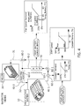
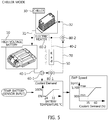
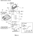
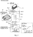
- FIGS. 4 to 7 illustrate the operation of the battery cooler 30 and the peripheral device in the mode operation of the battery heat management connection control S40
- FIGS. 8 to 11 illustrate the operation of the battery cooler 30 and the peripheral devices in the mode operation of the ambient temperature dependent control S60 and the ambient temperature separation control S70.
- the comparison for the same mode will be described. Referring to the radiator mode S40A in FIG. 4 and the radiator mode S60B in FIG. 8 , the radiator mode S40A and the radiator mode S60B implement only the cooling operation through the radiator 50 and the cooling fan 50-1 without the heat exchange effect by the battery cooler 30.
- the operation control of the BMS 100 is configured to operate the cooling water pump 60-1, open the path of the radiator path valve 80-1 to the via line 40-2, and operate the cooling fan 50-1.
- the flow path may be formed to allow the battery cooling water to flow from the battery 10 to the discharge line 40-1 to flow from the via line 40-2 into the radiator 50 through the radiator via valve 80-1, to flow from the radiator 50 into the return line 40-3 through the via line 40-2, and to flow from the return line 40-3 to the battery through the electric heater 60-2 and the cooler outlet line 32 of the battery cooling line 30-1.
- the battery cooling water is cooled by the heat exchange with the outside through the radiator 50, and the heat exchange effect may be increased through the blowing operation of the cooling fan 50-1.
- the radiator mode S40A in FIG. 4 matches a fan line diagram and a pump line diagram to a map table according to a battery cooling water temperature line diagram (or a battery temperature line diagram), and thus, the cooling fan 50-1 and the electric cooling water pump 60-1 may be operated based on the map table.
- the chiller mode S40B and the chiller modes S60A, S70A implement only the cooling operation through the battery cooler 30 without the heat exchange effect by the radiator 50 and the cooling fan 50-1.
- the operation control of the BMS 100 is configured to operate the cooling water pump 60-1, open the path of the radiator path valve 80-1 to the cooler connection line 70, and connect the path of the battery cooler path valve 80-2 to the cooler inlet line 31 of the battery cooling line 30-1.
- the flow path may be formed to allow the battery cooling water to flow from the battery 10 to the discharge line 40-1 to flow into the cooler connection line 70 through the radiator path valve 80-1, to flow from the cooler connection line 70 into the battery cooler 30 through the battery cooler path valve 80-2 and the cooler inlet line 31, and then return from the cooler outlet line 32 to the battery 10.
- the battery cooling water is cooled by the heat exchange operation with the air conditioner refrigerant of the air conditioning system 20 that circulates inside the battery cooler 30 through the cooler inlet line 33 and the cooler outlet line 34 of the air conditioning cooling line 30-2.
- the chiller mode S40B in FIG. 5 matches a pump line diagram to the map table according to a battery cooling water temperature line diagram (or a battery temperature line diagram), and thus, the electric cooling water pump 60-1 may be operated based on the map table.
- the maintenance mode S40C and the maintenance modes S60C, S70B implement only the circulation flow without the heat exchange effect by the battery cooler 30, the radiator 50, and the cooling fan 50-1.
- the operation control of the BMS 100 may be configured to operate the cooling water pump 60-1, open the path of the radiator path valve 80-1 to the cooler connection line 70, and open the path of the battery cooler path valve 80-2 to the via line 40-2.
- the flow path may be formed to allow the battery cooling water to flow from the battery 10 to the discharge line 40-1 to flow into the cooler connection line 70 through the radiator path valve 80-1, to flow into the return line 40-3 through the battery cooler path valve 80-2, and to flow from the return line 40-3 to the battery 10 through the electric heater 60-2 and the cooler outlet line 32 of the battery cooling line 30-1.
- the maintenance mode S40C in FIG. 6 matches a pump line diagram to the map table according to a battery cooling water temperature line diagram (or a battery temperature line diagram), and thus, the electric cooling water pump 60-1 may be operated based on the map table.
- the heater mode S40D and the heater modes S60D, S70C implement the heat exchange effect for the electric heater 60-2 instead of the heat exchange effect by the battery cooler 30, the radiator 50, and the cooling fan 50-1.
- the operation control of the BMS 100 may be configured to operate the cooling water pump 60-1, open the path of the radiator path valve 80-1 to the cooler connection line 70, and connect the path of the battery cooler path valve 80-2 to the via line 40-2.
- the flow path may be formed to allow the battery cooling water to flow from the battery 10 to the discharge line 40-1 to flow into the cooler connection line 70 through the radiator path valve 80-1, to flow into the return line 40-3 through the battery cooler path valve 80-2, and after performing the heat exchange operation with the electric heater 60-2 of the operating state in the return line 40-3, return to the battery 10 through the cooler outlet line 32 of the battery cooling line 30-1.
- the maintenance mode S40C in FIG. 7 matches a pump line diagram to the map table according to a battery cooling water temperature line diagram (or a battery temperature line diagram), and thus, the electric cooling water pump 60-1 may be operated based on the map table.
- the battery heat management integration system in accordance with the present embodiment includes the battery cooler 30 for connecting the battery 10 in which the battery cooling water is circulated and the air conditioning system 20 in which the air conditioner refrigerant is circulated.
- the heat exchange effect may occur between the battery cooling water and the air conditioner refrigerant, thus variously performing the battery heat management mode control that is divided into the radiator mode, the chiller mode, the maintenance mode, and the heater mode according to the battery temperature may be executed by the battery management system (BMS) 100.
- BMS battery management system
- the battery may be cooled in the summer using the battery cooler 30 and heated using the heat of the battery in the winter.
Landscapes
- Engineering & Computer Science (AREA)
- Manufacturing & Machinery (AREA)
- General Chemical & Material Sciences (AREA)
- Electrochemistry (AREA)
- Chemical Kinetics & Catalysis (AREA)
- Chemical & Material Sciences (AREA)
- Mechanical Engineering (AREA)
- Life Sciences & Earth Sciences (AREA)
- Transportation (AREA)
- Power Engineering (AREA)
- Sustainable Energy (AREA)
- Sustainable Development (AREA)
- Physics & Mathematics (AREA)
- Thermal Sciences (AREA)
- Automation & Control Theory (AREA)
- Secondary Cells (AREA)
- Electric Propulsion And Braking For Vehicles (AREA)
Claims (13)
- Batterie-Wärmemanagement-Integrationssystem (1), umfassend:eine Batteriekühleinrichtung (30), die eine Batterie (10), in der Batterie-Kühlwasser zirkuliert, und ein Klimaanlagensystem (20), in dem Klimaanlagen-Kühlmittel zirkuliert, verbindet und den Wärmeaustausch zwischen dem Batterie-Kühlwasser und dem Klimaanlagen-Kühlmittel bewirkt, einen Kühler (50), der die Wärmeaustauschwirkung auf das Batterie-Kühlwasser ausübt,eine Batterie-Kühlleitung (40), die eine Auslassleitung (40-1), die von der Batterie (10) verbunden ist, eine Durchleitungsleitung (40-2), die mit der Auslassleitung (40-1) verbunden ist, und eine Rückführleitung (40-3), die mit der Durchleitungsleitung (40-2) verbunden ist und mit der Batterie (10) verbunden ist, umfasst,einen Temperatursensor (90), der eingerichtet ist, um eine Temperatur der Batterie (10), eine Temperatur des Batterie-Kühlwassers und eine Umgebungstemperatur zu erfassen, und ein Batteriemanagementsystem (BMS) (100), das mit dem Temperatursensor (90) verbunden ist;dadurch gekennzeichnet, dassdas Batterie-Wärmemanagement-Integrationssystem (1) ferner ein Kühler-Wegeventil (80-1) und ein Batteriekühleinrichtungs-Wegeventil (80-2) umfasst,ein Strömungsweg des Kühler-Wegeventils (80-1) an dem Verbindungsteil einer Kühleinrichtungs-Verbindungsleitung (70), der Auslassleitung (40-1) und der Durchleitungsleitung (40-2) positioniert ist und ein Strömungsweg des Batteriekühleinrichtungs-Wegeventil (80-2) an dem Verbindungsteil der Kühleinrichtungs-Verbindungsleitung (70), der Rückführleitung (40-3) und einer Kühleinrichtungs-Zuleitung (31) einer Batterie-Kühlleitung (30-1) positioniert ist,die Batteriekühleinrichtung (30) eine Batterie-Kühlleitung (30-1), in der das Batterie-Kühlwasser zirkuliert, und eine Klimaanlagen-Kühlleitung (30-2), in der das Klimaanlagen-Kühlmittel zirkuliert, umfasst,die Batterie-Kühlleitung (30-1) eine Kühleinrichtungs-Zuleitung (31) zum Auslassen des Batterie-Kühlwassers, das aus der Batterie (10) stammt, in die Batteriekühleinrichtung (30), und eine Kühleinrichtungs-Ableitung (32) zum Rückführen des Batterie-Kühlwassers, das aus der Batteriekühleinrichtung (30) stammt, zu der Batterie (10) umfasst; und die Klimaanlagen-Kühlleitung (30-2) eine Kühleinrichtungs-Zuleitung (33) zum Auslassen des Klimaanlagen-Kühlmittels, das aus dem Klimaanlagensystem (20) stammt, in die Batteriekühleinrichtung (30) und eine Kühleinrichtungs-Ableitung (34) zum Rückführen des Klimaanlagen-Kühlmittels, das aus der Batteriekühleinrichtung (30) stammt, zu dem Klimaanlagensystem (20) umfasst,die Kühleinrichtungs-Zuleitung (31) der Batterie-Kühlleitung (30-1) mit einer Kühleinrichtungs-Verbindungsleitung (70) verbunden ist, die mit der Batterie-Kühlleitung (40) verbunden ist, um das Batterie-Kühlwasser zu dem Kühler (50) zirkulieren zu lassen,die Auslassleitung (40-1) von der Batterie (10) mit der Kühleinrichtungs-Verbindungsleitung (70) verbunden ist, die mit der Kühleinrichtungs-Zuleitung (31) verbunden ist, die Durchleitungsleitung (40-2) mit der Auslassleitung (40-1) verbunden ist, um durch den Kühler (50) zu verlaufen, und die Rückführleitung (40-3) mit der Durchleitungsleitung (40-2) verbunden ist, um mit der Batterie (10) verbunden zu sein,der Temperatursensor (90) eingerichtet ist, um dem BMS (100) die erfassten Temperaturen bereitzustellen, unddas BMS (100) eingerichtet ist, um die Öffnung des Kühler-Wegeventils (80-1) und des Batteriekühleinrichtungs-Wegeventils (80-2) gemäß den Temperaturen zu steuern, um die Richtung des Strömungswegs des Kühler-Wegeventils (80-1) und des Strömungswegs des Batteriekühleinrichtungs-Wegeventils (80-2) zu ändern,wobei der Strömungsweg gebildet ist, um für den Fall, dass der Weg des Kühler-Wegeventils (80-1) zu dem Kühler (50) geöffnet wird, zu ermöglichen, dass das Batterie-Kühlwasser von der Batterie (10) zu der Auslassleitung (40-1) strömt, von der Durchleitungsleitung (40-2) durch das Kühler-Durchleitungsventil (80-1) in den Kühler (50) strömt, von dem Kühler (50) durch die Durchleitungsleitung (40-2) in die Rückführleitung (40-3) strömt und von der Rückführleitung (40-3) zu der Batterie (10) strömt, wohingegen der Strömungsweg gebildet ist, um für den Fall, dass der Weg des Kühler-Wegeventils (80-1) zu dem Weg desBatteriekühleinrichtungs-Wegeventil (80-2) geöffnet wird und der Weg des Batteriekühleinrichtungs-Wegeventils (80-2) zu dem Klimaanlagensystem (20) geöffnet wird, zu ermöglichen, dass das Batterie-Kühlwasser von der Batterie (10) zu der Auslassleitung (40-1) strömt, durch das Kühler-Wegeventil (80-1) in die Kühleinrichtungs-Verbindungsleitung (70) strömt, von der Kühleinrichtungs-Verbindungsleitung (70) durch das Batteriekühleinrichtungs-Wegeventil (80-2) und die Kühleinrichtungs-Zuleitung (31) in die Batteriekühleinrichtung (30) strömt und von der Kühleinrichtungs-Ableitung (32) zu der Batterie (10) zurückkehrt.
- Batterie-Wärmemanagement-Integrationssystem (1) nach Anspruch 1, wobei das BMS (100) eingerichtet ist, um einen Kühlventilator (50-1), eine Kühlwasserpumpe (60-1) und ein elektrisches Heizgerät (60-2) zu betreiben, wobei der Kühlventilator (50-1) auf dem Kühler (50) vorgesehen ist, wobei die Kühlwasserpumpe (60-1) auf der Auslassleitung (40-1) vorgesehen ist und wobei das elektrische Heizgerät (60-2) auf der Rückführleitung (40-3) vorgesehen ist.
- Batterie-Wärmemanagement-Integrationssystem (1) nach Anspruch 1, wobei der Temperatursensor (90) einen Batterietemperatursensor (90-1), der eingerichtet ist, um die Batteriezellentemperatur der Batterie (10) zu erfassen, einen Batterie-Kühlwasser-Temperatursensor (90-2), der eingerichtet ist, um die Temperatur des Batterie-Kühlwassers zu erfassen, und einen Umgebungstemperatursensor (90-3) der eingerichtet ist, um eine Atmosphärentemperatur als die Umgebungstemperatur zu erfassen, umfasst.
- Batterie-Wärmemanagement-Integrationssystem (1) nach Anspruch 1, wobei das BMS (100) mit einem Klimaanlagen-Bedienfeld (200) zum Ausführen eines Betriebsmodus des Klimaanlagensystems (20) verbunden ist und das BMS (100) mit dem Klimaanlagen-Bedienfeld (200) in Kommunikation steht, um in einem Kältemaschinenmodus (S40B, S60A, S70A) den Wärmeaustauschbetrieb der Batteriekühleinrichtung (30) durchzuführen.
- Batterie-Wärmemanagement-Integrationssystem (1) nach Anspruch 4, wobei das BMS (100) eingerichtet ist, um in dem Kältemaschinenmodus (S40B, S60A, S70A) einen zu der Batterietemperatur proportionalen Wert der Batterie (10) an das Klimaanlagen-Bedienfeld (20) zu übertragen.
- Verfahren zum Betreiben eines Batterie-Wärmemanagement-Integrationssystems (1) nach einem der Ansprüche 1 bis 5, umfassend:Ausführen, durch eine Steuerung des BMS (100), einer Batterie-Wärmemanagement-Modussteuerung eines Batterie-Wärmemanagement-Modus für eine Batterie, der in einen Kühlermodus (S40A, S60B), einen Kältemaschinenmodus (S40B, S60A, S70A), einen Aufrechterhaltungsmodus (S40C, S60C, S70B) und einen Heizgerätemodus (S40D, S60D, S70C) unterteilt ist; undErfassen, durch die Steuerung, ob das Klimaanlagensystem (20) in Betrieb ist, um einen Modusumschaltzustand für den Kühlermodus (S40A, S60B), den Kältemaschinenmodus (S40B, S60A, S70A), den Aufrechterhaltungsmodus (S40C, S60C, S70B) und den Heizgerätemodus (S40D, S60D, S70C) zu ändern, und dadurch gekennzeichnet, dassim Falle des Kühlermodus (S40A, S60B) das Batterie-Kühlwasser durch den Kühler (50) durch den Wärmeaustausch mit außen gekühlt wird, wenn der Betrieb des BMS (100) den Weg des Kühler-Wegeventils (80-1) zu dem Kühler (50) öffnet, wohingegen im Falle des Kältemaschinenmodus (S40B, S60A, S70A) das Batterie-Kühlwasser durch den Wärmeaustausch mit dem Klimaanlagen-Kühlmittel des Klimaanlagensystems (20) gekühlt wird, das im Inneren der Batteriekühleinrichtung (30) zirkuliert, wenn der Betrieb des BMS (100) das Kühler-Wegeventil (80-1) zu dem Weg des Batteriekühleinrichtungs-Wegeventils (80-2) und den Weg des Batteriekühleinrichtungs-Wegeventils (80-2) zu dem Klimaanlagensystem (20) öffnet.
- Verfahren nach Anspruch 6, ferner umfassend:
Bestimmen, durch die Steuerung, ob der Betrieb in der Reihenfolge des Kühlermodus (S40A), des Kältemaschinenmodus (S40B), des Aufrechterhaltungsmodus (S40C) und des Heizgerätemodus (S40D) durchgeführt wird, gemäß einer Batterieerfassungstemperatur, wenn das Klimaanlagensystem (20) betrieben wird. - Verfahren nach Anspruch 7, wobei der Kühlermodus (S40A) und der Kältemaschinenmodus (S40B), der Kältemaschinenmodus (S40B) und der Aufrechterhaltungsmodus (S40C) sowie der Aufrechterhaltungsmodus (S40C) und der Heizgerätemodus (S40D) gemeinsam gemäß der Batterieerfassungstemperatur umgeschaltet werden.
- Verfahren nach Anspruch 6, wobei die Batterie-Wärmemanagement-Modussteuerung in eine von der Umgebungstemperatur abhängige Steuerung (S60) und eine Umgebungstemperatur-Trennungssteuerung (S70) gemäß einer Umgebungstemperatur unterteilt wird, wenn das Klimaanlagensystem (20) nicht betrieben wird.
- Verfahren nach Anspruch 9, wobei die von der Umgebungstemperatur abhängige Steuerung (S60) umfasst:
Bestimmen, durch die Steuerung, ob der Betrieb in der Reihenfolge des Kältemaschinenmodus (S60A), des Kühlermodus (S60B), des Aufrechterhaltungsmodus (S60C) und des Heizgerätemodus (S60D) durchgeführt wird, gemäß der Batterieerfassungstemperatur. - Verfahren nach Anspruch 10, wobei der Kältemaschinenmodus (S60A) und der Kühlermodus (S60B), der Kühlermodus (S60B) und der Aufrechterhaltungsmodus (S60C) sowie der Aufrechterhaltungsmodus (S60C) und der Heizgerätemodus (S60D) gemeinsam gemäß der Batterieerfassungstemperatur umgeschaltet werden.
- Verfahren nach Anspruch 9, wobei die Umgebungstemperatur-Trennungssteuerung (S70) umfasst:
Bestimmen, durch die Steuerung, ob der Betrieb in der Reihenfolge des Kältemaschinenmodus (S70A), des Aufrechterhaltungsmodus (S70B) und des Heizgerätemodus (S70C) durchgeführt wird, gemäß der Batterieerfassungstemperatur. - Verfahren nach Anspruch 12, wobei der Kältemaschinenmodus (S70A) und der Aufrechterhaltungsmodus (S70B) sowie der Aufrechterhaltungsmodus (S70B) und der Heizgerätemodus (S70C) gemeinsam gemäß der Batterieerfassungstemperatur umgeschaltet werden.
Applications Claiming Priority (1)
| Application Number | Priority Date | Filing Date | Title |
|---|---|---|---|
| KR1020180084097A KR102726687B1 (ko) | 2018-07-19 | 2018-07-19 | 배터리 열관리 통합 시스템 및 그 운영방법 |
Publications (2)
| Publication Number | Publication Date |
|---|---|
| EP3598565A1 EP3598565A1 (de) | 2020-01-22 |
| EP3598565B1 true EP3598565B1 (de) | 2021-10-13 |
Family
ID=64606890
Family Applications (1)
| Application Number | Title | Priority Date | Filing Date |
|---|---|---|---|
| EP18210503.1A Active EP3598565B1 (de) | 2018-07-19 | 2018-12-05 | Batteriewärmeverwaltungintegrationssystem und betriebsverfahren dafür |
Country Status (4)
| Country | Link |
|---|---|
| US (1) | US11097635B2 (de) |
| EP (1) | EP3598565B1 (de) |
| KR (1) | KR102726687B1 (de) |
| CN (1) | CN110739508A (de) |
Cited By (1)
| Publication number | Priority date | Publication date | Assignee | Title |
|---|---|---|---|---|
| US20220258568A1 (en) * | 2019-07-17 | 2022-08-18 | Daimler Ag | Cooling Apparatus for Vehicle |
Families Citing this family (12)
| Publication number | Priority date | Publication date | Assignee | Title |
|---|---|---|---|---|
| DE102018215836A1 (de) * | 2018-09-18 | 2020-03-19 | Mahle International Gmbh | Modulare Aufdachklimaanlage |
| CN111261977B (zh) * | 2018-11-30 | 2025-01-28 | 株式会社斯巴鲁 | 车辆的电池加热装置 |
| CN111725584B (zh) * | 2020-06-22 | 2021-08-20 | 厦门金龙旅行车有限公司 | 一种电动车电池冷却装置及方法 |
| KR102745420B1 (ko) | 2022-01-12 | 2024-12-20 | 주식회사 세기하이텍 | 배터리 온도 조절모듈 |
| CN114899529A (zh) * | 2022-05-10 | 2022-08-12 | 新科环保科技有限公司 | 一种节能空调冷却系统 |
| US12297771B2 (en) * | 2022-07-08 | 2025-05-13 | Rolls-Royce Corporation | Energy storage system heater control architecture |
| US12567613B2 (en) | 2022-08-25 | 2026-03-03 | Rolls-Royce Corporation | Aircraft thermal management system for an energy storage system |
| CN115923439A (zh) * | 2022-11-30 | 2023-04-07 | 中国第一汽车股份有限公司 | 一种新型热管理集成系统、方法及混合动力汽车 |
| EP4628358A4 (de) * | 2022-12-01 | 2025-12-31 | Nissan Motor | Steuerungsverfahren für elektrofahrzeug und steuerungssystem für elektrofahrzeug |
| EP4553935A1 (de) | 2023-11-09 | 2025-05-14 | H2X Ecosystems | Hybridsystem |
| KR20250163108A (ko) | 2024-05-13 | 2025-11-20 | 주식회사 한중엔시에스 | Ess 배터리용 칠러 운영시스템 및 그 운영방법 |
| KR20250163116A (ko) | 2024-05-13 | 2025-11-20 | 주식회사 한중엔시에스 | Ess 배터리용 칠러 운영시스템 및 그 운영방법 |
Family Cites Families (10)
| Publication number | Priority date | Publication date | Assignee | Title |
|---|---|---|---|---|
| WO2011111949A2 (ko) * | 2010-03-08 | 2011-09-15 | (주)브이이엔에스 | 자동차 및 그의 제어방법 |
| US8336319B2 (en) | 2010-06-04 | 2012-12-25 | Tesla Motors, Inc. | Thermal management system with dual mode coolant loops |
| CN102290618B (zh) * | 2011-07-26 | 2013-11-06 | 浙江吉利汽车研究院有限公司 | 一种车用电池热管理系统 |
| US20160351981A1 (en) * | 2015-05-26 | 2016-12-01 | Ford Global Technologies, Llc | Cooling modes to manage a high voltage battery for a vehicle |
| KR101855759B1 (ko) * | 2015-12-08 | 2018-05-09 | 현대자동차 주식회사 | 차량용 배터리 냉각 시스템 |
| KR102523026B1 (ko) | 2016-02-05 | 2023-04-19 | 한온시스템 주식회사 | 차량용 배터리의 열관리 시스템 |
| KR20170108447A (ko) * | 2016-03-17 | 2017-09-27 | 현대자동차주식회사 | 차량용 배터리 냉각 시스템 제어방법 |
| CN106092603B (zh) | 2016-06-15 | 2019-10-15 | 北京长城华冠汽车科技股份有限公司 | 一种电动汽车动力系统的测试系统和电动汽车 |
| KR101776751B1 (ko) * | 2016-06-21 | 2017-09-08 | 현대자동차 주식회사 | 차량용 배터리 냉각 시스템 제어방법 |
| KR101875649B1 (ko) | 2016-10-26 | 2018-07-06 | 현대자동차 주식회사 | 차량용 배터리 냉각 시스템 |
-
2018
- 2018-07-19 KR KR1020180084097A patent/KR102726687B1/ko active Active
- 2018-11-28 US US16/202,770 patent/US11097635B2/en active Active
- 2018-12-05 EP EP18210503.1A patent/EP3598565B1/de active Active
- 2018-12-06 CN CN201811488545.6A patent/CN110739508A/zh active Pending
Non-Patent Citations (1)
| Title |
|---|
| None * |
Cited By (2)
| Publication number | Priority date | Publication date | Assignee | Title |
|---|---|---|---|---|
| US20220258568A1 (en) * | 2019-07-17 | 2022-08-18 | Daimler Ag | Cooling Apparatus for Vehicle |
| US12194812B2 (en) * | 2019-07-17 | 2025-01-14 | Daimler Truck AG | Cooling apparatus for vehicle |
Also Published As
| Publication number | Publication date |
|---|---|
| EP3598565A1 (de) | 2020-01-22 |
| KR20200009566A (ko) | 2020-01-30 |
| CN110739508A (zh) | 2020-01-31 |
| KR102726687B1 (ko) | 2024-11-06 |
| US20200023751A1 (en) | 2020-01-23 |
| US11097635B2 (en) | 2021-08-24 |
Similar Documents
| Publication | Publication Date | Title |
|---|---|---|
| EP3598565B1 (de) | Batteriewärmeverwaltungintegrationssystem und betriebsverfahren dafür | |
| CN107554235B (zh) | 电池冷却剂回路控制 | |
| US9701215B1 (en) | Method of controlling battery cooling system for vehicle | |
| CN107565189B (zh) | 电池冷却剂回路控制 | |
| US9555691B2 (en) | Climate-control device and method for its operation | |
| US8679659B2 (en) | Temperature control of a vehicle battery | |
| US11364769B2 (en) | Vehicle cabin thermal management system and control methods | |
| US20120291987A1 (en) | System for a motor vehicle for heating and/or cooling a battery and a vehicle interior | |
| US9067476B2 (en) | Temperature control apparatus for vehicle | |
| CN113580871B (zh) | 车辆及其热管理系统 | |
| US11890914B2 (en) | Balancing battery heating and cabin heating with shared thermal-management system | |
| CN112389276B (zh) | 一种纯电动汽车热管理系统 | |
| CN115139737B (zh) | 一种电动车整车热管理系统及控制方法 | |
| KR102160631B1 (ko) | 전기 자동차의 고전압배터리 온도 관리 제어시스템 및 제어방법 | |
| WO2020129491A1 (ja) | 電池昇温装置 | |
| JP2021035214A (ja) | 車両 | |
| CN112277572A (zh) | 用于车辆的车厢空调系统以及控制所述车辆和系统的方法 | |
| CN118156667A (zh) | 热管理系统、热管理方法和计算机装置 | |
| CN113580872A (zh) | 车辆及其热管理系统 | |
| US20220305885A1 (en) | Integrated thermal management circuit for vehicle | |
| CN115817099B (zh) | 电动汽车热管理系统及方法 | |
| CN112977158A (zh) | 电动汽车的热管理方法、装置、整车控制器及电动汽车 | |
| CN113954697A (zh) | 燃料电池辅助系统与电池热管理集成系统及其控制方法 | |
| CN119261475A (zh) | 车辆的热管理系统及其控制方法 | |
| CN216033738U (zh) | 整车热管理系统以及车辆 |
Legal Events
| Date | Code | Title | Description |
|---|---|---|---|
| PUAI | Public reference made under article 153(3) epc to a published international application that has entered the european phase |
Free format text: ORIGINAL CODE: 0009012 |
|
| STAA | Information on the status of an ep patent application or granted ep patent |
Free format text: STATUS: THE APPLICATION HAS BEEN PUBLISHED |
|
| AK | Designated contracting states |
Kind code of ref document: A1 Designated state(s): AL AT BE BG CH CY CZ DE DK EE ES FI FR GB GR HR HU IE IS IT LI LT LU LV MC MK MT NL NO PL PT RO RS SE SI SK SM TR |
|
| AX | Request for extension of the european patent |
Extension state: BA ME |
|
| STAA | Information on the status of an ep patent application or granted ep patent |
Free format text: STATUS: REQUEST FOR EXAMINATION WAS MADE |
|
| 17P | Request for examination filed |
Effective date: 20200318 |
|
| RBV | Designated contracting states (corrected) |
Designated state(s): AL AT BE BG CH CY CZ DE DK EE ES FI FR GB GR HR HU IE IS IT LI LT LU LV MC MK MT NL NO PL PT RO RS SE SI SK SM TR |
|
| STAA | Information on the status of an ep patent application or granted ep patent |
Free format text: STATUS: EXAMINATION IS IN PROGRESS |
|
| 17Q | First examination report despatched |
Effective date: 20200805 |
|
| GRAP | Despatch of communication of intention to grant a patent |
Free format text: ORIGINAL CODE: EPIDOSNIGR1 |
|
| STAA | Information on the status of an ep patent application or granted ep patent |
Free format text: STATUS: GRANT OF PATENT IS INTENDED |
|
| INTG | Intention to grant announced |
Effective date: 20210503 |
|
| RAP3 | Party data changed (applicant data changed or rights of an application transferred) |
Owner name: HYUNDAI MOTOR COMPANY Owner name: KIA CORPORATION |
|
| GRAS | Grant fee paid |
Free format text: ORIGINAL CODE: EPIDOSNIGR3 |
|
| GRAA | (expected) grant |
Free format text: ORIGINAL CODE: 0009210 |
|
| STAA | Information on the status of an ep patent application or granted ep patent |
Free format text: STATUS: THE PATENT HAS BEEN GRANTED |
|
| AK | Designated contracting states |
Kind code of ref document: B1 Designated state(s): AL AT BE BG CH CY CZ DE DK EE ES FI FR GB GR HR HU IE IS IT LI LT LU LV MC MK MT NL NO PL PT RO RS SE SI SK SM TR |
|
| REG | Reference to a national code |
Ref country code: GB Ref legal event code: FG4D |
|
| REG | Reference to a national code |
Ref country code: CH Ref legal event code: EP |
|
| REG | Reference to a national code |
Ref country code: DE Ref legal event code: R096 Ref document number: 602018024913 Country of ref document: DE |
|
| REG | Reference to a national code |
Ref country code: IE Ref legal event code: FG4D |
|
| REG | Reference to a national code |
Ref country code: AT Ref legal event code: REF Ref document number: 1438835 Country of ref document: AT Kind code of ref document: T Effective date: 20211115 |
|
| REG | Reference to a national code |
Ref country code: LT Ref legal event code: MG9D |
|
| REG | Reference to a national code |
Ref country code: NL Ref legal event code: MP Effective date: 20211013 |
|
| REG | Reference to a national code |
Ref country code: AT Ref legal event code: MK05 Ref document number: 1438835 Country of ref document: AT Kind code of ref document: T Effective date: 20211013 |
|
| PG25 | Lapsed in a contracting state [announced via postgrant information from national office to epo] |
Ref country code: RS Free format text: LAPSE BECAUSE OF FAILURE TO SUBMIT A TRANSLATION OF THE DESCRIPTION OR TO PAY THE FEE WITHIN THE PRESCRIBED TIME-LIMIT Effective date: 20211013 Ref country code: LT Free format text: LAPSE BECAUSE OF FAILURE TO SUBMIT A TRANSLATION OF THE DESCRIPTION OR TO PAY THE FEE WITHIN THE PRESCRIBED TIME-LIMIT Effective date: 20211013 Ref country code: FI Free format text: LAPSE BECAUSE OF FAILURE TO SUBMIT A TRANSLATION OF THE DESCRIPTION OR TO PAY THE FEE WITHIN THE PRESCRIBED TIME-LIMIT Effective date: 20211013 Ref country code: BG Free format text: LAPSE BECAUSE OF FAILURE TO SUBMIT A TRANSLATION OF THE DESCRIPTION OR TO PAY THE FEE WITHIN THE PRESCRIBED TIME-LIMIT Effective date: 20220113 Ref country code: AT Free format text: LAPSE BECAUSE OF FAILURE TO SUBMIT A TRANSLATION OF THE DESCRIPTION OR TO PAY THE FEE WITHIN THE PRESCRIBED TIME-LIMIT Effective date: 20211013 |
|
| PG25 | Lapsed in a contracting state [announced via postgrant information from national office to epo] |
Ref country code: IS Free format text: LAPSE BECAUSE OF FAILURE TO SUBMIT A TRANSLATION OF THE DESCRIPTION OR TO PAY THE FEE WITHIN THE PRESCRIBED TIME-LIMIT Effective date: 20220213 Ref country code: SE Free format text: LAPSE BECAUSE OF FAILURE TO SUBMIT A TRANSLATION OF THE DESCRIPTION OR TO PAY THE FEE WITHIN THE PRESCRIBED TIME-LIMIT Effective date: 20211013 Ref country code: PT Free format text: LAPSE BECAUSE OF FAILURE TO SUBMIT A TRANSLATION OF THE DESCRIPTION OR TO PAY THE FEE WITHIN THE PRESCRIBED TIME-LIMIT Effective date: 20220214 Ref country code: PL Free format text: LAPSE BECAUSE OF FAILURE TO SUBMIT A TRANSLATION OF THE DESCRIPTION OR TO PAY THE FEE WITHIN THE PRESCRIBED TIME-LIMIT Effective date: 20211013 Ref country code: NO Free format text: LAPSE BECAUSE OF FAILURE TO SUBMIT A TRANSLATION OF THE DESCRIPTION OR TO PAY THE FEE WITHIN THE PRESCRIBED TIME-LIMIT Effective date: 20220113 Ref country code: NL Free format text: LAPSE BECAUSE OF FAILURE TO SUBMIT A TRANSLATION OF THE DESCRIPTION OR TO PAY THE FEE WITHIN THE PRESCRIBED TIME-LIMIT Effective date: 20211013 Ref country code: LV Free format text: LAPSE BECAUSE OF FAILURE TO SUBMIT A TRANSLATION OF THE DESCRIPTION OR TO PAY THE FEE WITHIN THE PRESCRIBED TIME-LIMIT Effective date: 20211013 Ref country code: HR Free format text: LAPSE BECAUSE OF FAILURE TO SUBMIT A TRANSLATION OF THE DESCRIPTION OR TO PAY THE FEE WITHIN THE PRESCRIBED TIME-LIMIT Effective date: 20211013 Ref country code: GR Free format text: LAPSE BECAUSE OF FAILURE TO SUBMIT A TRANSLATION OF THE DESCRIPTION OR TO PAY THE FEE WITHIN THE PRESCRIBED TIME-LIMIT Effective date: 20220114 Ref country code: ES Free format text: LAPSE BECAUSE OF FAILURE TO SUBMIT A TRANSLATION OF THE DESCRIPTION OR TO PAY THE FEE WITHIN THE PRESCRIBED TIME-LIMIT Effective date: 20211013 |
|
| REG | Reference to a national code |
Ref country code: DE Ref legal event code: R097 Ref document number: 602018024913 Country of ref document: DE |
|
| PG25 | Lapsed in a contracting state [announced via postgrant information from national office to epo] |
Ref country code: SM Free format text: LAPSE BECAUSE OF FAILURE TO SUBMIT A TRANSLATION OF THE DESCRIPTION OR TO PAY THE FEE WITHIN THE PRESCRIBED TIME-LIMIT Effective date: 20211013 Ref country code: SK Free format text: LAPSE BECAUSE OF FAILURE TO SUBMIT A TRANSLATION OF THE DESCRIPTION OR TO PAY THE FEE WITHIN THE PRESCRIBED TIME-LIMIT Effective date: 20211013 Ref country code: RO Free format text: LAPSE BECAUSE OF FAILURE TO SUBMIT A TRANSLATION OF THE DESCRIPTION OR TO PAY THE FEE WITHIN THE PRESCRIBED TIME-LIMIT Effective date: 20211013 Ref country code: MC Free format text: LAPSE BECAUSE OF FAILURE TO SUBMIT A TRANSLATION OF THE DESCRIPTION OR TO PAY THE FEE WITHIN THE PRESCRIBED TIME-LIMIT Effective date: 20211013 Ref country code: EE Free format text: LAPSE BECAUSE OF FAILURE TO SUBMIT A TRANSLATION OF THE DESCRIPTION OR TO PAY THE FEE WITHIN THE PRESCRIBED TIME-LIMIT Effective date: 20211013 Ref country code: DK Free format text: LAPSE BECAUSE OF FAILURE TO SUBMIT A TRANSLATION OF THE DESCRIPTION OR TO PAY THE FEE WITHIN THE PRESCRIBED TIME-LIMIT Effective date: 20211013 Ref country code: CZ Free format text: LAPSE BECAUSE OF FAILURE TO SUBMIT A TRANSLATION OF THE DESCRIPTION OR TO PAY THE FEE WITHIN THE PRESCRIBED TIME-LIMIT Effective date: 20211013 |
|
| REG | Reference to a national code |
Ref country code: CH Ref legal event code: PL |
|
| PLBE | No opposition filed within time limit |
Free format text: ORIGINAL CODE: 0009261 |
|
| STAA | Information on the status of an ep patent application or granted ep patent |
Free format text: STATUS: NO OPPOSITION FILED WITHIN TIME LIMIT |
|
| 26N | No opposition filed |
Effective date: 20220714 |
|
| REG | Reference to a national code |
Ref country code: BE Ref legal event code: MM Effective date: 20211231 |
|
| PG25 | Lapsed in a contracting state [announced via postgrant information from national office to epo] |
Ref country code: LU Free format text: LAPSE BECAUSE OF NON-PAYMENT OF DUE FEES Effective date: 20211205 Ref country code: IE Free format text: LAPSE BECAUSE OF NON-PAYMENT OF DUE FEES Effective date: 20211205 Ref country code: AL Free format text: LAPSE BECAUSE OF FAILURE TO SUBMIT A TRANSLATION OF THE DESCRIPTION OR TO PAY THE FEE WITHIN THE PRESCRIBED TIME-LIMIT Effective date: 20211013 |
|
| PG25 | Lapsed in a contracting state [announced via postgrant information from national office to epo] |
Ref country code: SI Free format text: LAPSE BECAUSE OF FAILURE TO SUBMIT A TRANSLATION OF THE DESCRIPTION OR TO PAY THE FEE WITHIN THE PRESCRIBED TIME-LIMIT Effective date: 20211013 Ref country code: BE Free format text: LAPSE BECAUSE OF NON-PAYMENT OF DUE FEES Effective date: 20211231 |
|
| PG25 | Lapsed in a contracting state [announced via postgrant information from national office to epo] |
Ref country code: LI Free format text: LAPSE BECAUSE OF NON-PAYMENT OF DUE FEES Effective date: 20211231 Ref country code: CH Free format text: LAPSE BECAUSE OF NON-PAYMENT OF DUE FEES Effective date: 20211231 |
|
| PG25 | Lapsed in a contracting state [announced via postgrant information from national office to epo] |
Ref country code: IT Free format text: LAPSE BECAUSE OF FAILURE TO SUBMIT A TRANSLATION OF THE DESCRIPTION OR TO PAY THE FEE WITHIN THE PRESCRIBED TIME-LIMIT Effective date: 20211013 |
|
| P01 | Opt-out of the competence of the unified patent court (upc) registered |
Effective date: 20230512 |
|
| PG25 | Lapsed in a contracting state [announced via postgrant information from national office to epo] |
Ref country code: CY Free format text: LAPSE BECAUSE OF FAILURE TO SUBMIT A TRANSLATION OF THE DESCRIPTION OR TO PAY THE FEE WITHIN THE PRESCRIBED TIME-LIMIT Effective date: 20211013 |
|
| PG25 | Lapsed in a contracting state [announced via postgrant information from national office to epo] |
Ref country code: HU Free format text: LAPSE BECAUSE OF FAILURE TO SUBMIT A TRANSLATION OF THE DESCRIPTION OR TO PAY THE FEE WITHIN THE PRESCRIBED TIME-LIMIT; INVALID AB INITIO Effective date: 20181205 |
|
| PG25 | Lapsed in a contracting state [announced via postgrant information from national office to epo] |
Ref country code: MK Free format text: LAPSE BECAUSE OF FAILURE TO SUBMIT A TRANSLATION OF THE DESCRIPTION OR TO PAY THE FEE WITHIN THE PRESCRIBED TIME-LIMIT Effective date: 20211013 |
|
| PG25 | Lapsed in a contracting state [announced via postgrant information from national office to epo] |
Ref country code: TR Free format text: LAPSE BECAUSE OF FAILURE TO SUBMIT A TRANSLATION OF THE DESCRIPTION OR TO PAY THE FEE WITHIN THE PRESCRIBED TIME-LIMIT Effective date: 20211013 |
|
| PG25 | Lapsed in a contracting state [announced via postgrant information from national office to epo] |
Ref country code: MT Free format text: LAPSE BECAUSE OF FAILURE TO SUBMIT A TRANSLATION OF THE DESCRIPTION OR TO PAY THE FEE WITHIN THE PRESCRIBED TIME-LIMIT Effective date: 20211013 |
|
| PGFP | Annual fee paid to national office [announced via postgrant information from national office to epo] |
Ref country code: DE Payment date: 20251120 Year of fee payment: 8 |
|
| PGFP | Annual fee paid to national office [announced via postgrant information from national office to epo] |
Ref country code: GB Payment date: 20251120 Year of fee payment: 8 |
|
| PGFP | Annual fee paid to national office [announced via postgrant information from national office to epo] |
Ref country code: FR Payment date: 20251125 Year of fee payment: 8 |