EP3598548B1 - Betriebsverfahren für eine brennstoffzelle - Google Patents
Betriebsverfahren für eine brennstoffzelle Download PDFInfo
- Publication number
- EP3598548B1 EP3598548B1 EP19186257.2A EP19186257A EP3598548B1 EP 3598548 B1 EP3598548 B1 EP 3598548B1 EP 19186257 A EP19186257 A EP 19186257A EP 3598548 B1 EP3598548 B1 EP 3598548B1
- Authority
- EP
- European Patent Office
- Prior art keywords
- bipolar plates
- fuel cell
- operating method
- cooling
- membrane units
- Prior art date
- Legal status (The legal status is an assumption and is not a legal conclusion. Google has not performed a legal analysis and makes no representation as to the accuracy of the status listed.)
- Not-in-force
Links
Images

Classifications
-
- H—ELECTRICITY
- H01—ELECTRIC ELEMENTS
- H01M—PROCESSES OR MEANS, e.g. BATTERIES, FOR THE DIRECT CONVERSION OF CHEMICAL ENERGY INTO ELECTRICAL ENERGY
- H01M8/00—Fuel cells; Manufacture thereof
- H01M8/02—Details
- H01M8/0202—Collectors; Separators, e.g. bipolar separators; Interconnectors
- H01M8/0204—Non-porous and characterised by the material
- H01M8/0206—Metals or alloys
-
- H—ELECTRICITY
- H01—ELECTRIC ELEMENTS
- H01M—PROCESSES OR MEANS, e.g. BATTERIES, FOR THE DIRECT CONVERSION OF CHEMICAL ENERGY INTO ELECTRICAL ENERGY
- H01M8/00—Fuel cells; Manufacture thereof
- H01M8/02—Details
- H01M8/0202—Collectors; Separators, e.g. bipolar separators; Interconnectors
- H01M8/0204—Non-porous and characterised by the material
- H01M8/0206—Metals or alloys
- H01M8/0208—Alloys
-
- H—ELECTRICITY
- H01—ELECTRIC ELEMENTS
- H01M—PROCESSES OR MEANS, e.g. BATTERIES, FOR THE DIRECT CONVERSION OF CHEMICAL ENERGY INTO ELECTRICAL ENERGY
- H01M8/00—Fuel cells; Manufacture thereof
- H01M8/02—Details
- H01M8/0202—Collectors; Separators, e.g. bipolar separators; Interconnectors
- H01M8/0204—Non-porous and characterised by the material
- H01M8/0213—Gas-impermeable carbon-containing materials
-
- H—ELECTRICITY
- H01—ELECTRIC ELEMENTS
- H01M—PROCESSES OR MEANS, e.g. BATTERIES, FOR THE DIRECT CONVERSION OF CHEMICAL ENERGY INTO ELECTRICAL ENERGY
- H01M8/00—Fuel cells; Manufacture thereof
- H01M8/02—Details
- H01M8/0202—Collectors; Separators, e.g. bipolar separators; Interconnectors
- H01M8/0258—Collectors; Separators, e.g. bipolar separators; Interconnectors characterised by the configuration of channels, e.g. by the flow field of the reactant or coolant
-
- H—ELECTRICITY
- H01—ELECTRIC ELEMENTS
- H01M—PROCESSES OR MEANS, e.g. BATTERIES, FOR THE DIRECT CONVERSION OF CHEMICAL ENERGY INTO ELECTRICAL ENERGY
- H01M8/00—Fuel cells; Manufacture thereof
- H01M8/02—Details
- H01M8/0202—Collectors; Separators, e.g. bipolar separators; Interconnectors
- H01M8/0267—Collectors; Separators, e.g. bipolar separators; Interconnectors having heating or cooling means, e.g. heaters or coolant flow channels
-
- H—ELECTRICITY
- H01—ELECTRIC ELEMENTS
- H01M—PROCESSES OR MEANS, e.g. BATTERIES, FOR THE DIRECT CONVERSION OF CHEMICAL ENERGY INTO ELECTRICAL ENERGY
- H01M8/00—Fuel cells; Manufacture thereof
- H01M8/04—Auxiliary arrangements, e.g. for control of pressure or for circulation of fluids
- H01M8/04007—Auxiliary arrangements, e.g. for control of pressure or for circulation of fluids related to heat exchange
- H01M8/04067—Heat exchange or temperature measuring elements, thermal insulation, e.g. heat pipes, heat pumps, fins
-
- H—ELECTRICITY
- H01—ELECTRIC ELEMENTS
- H01M—PROCESSES OR MEANS, e.g. BATTERIES, FOR THE DIRECT CONVERSION OF CHEMICAL ENERGY INTO ELECTRICAL ENERGY
- H01M2250/00—Fuel cells for particular applications; Specific features of fuel cell system
- H01M2250/20—Fuel cells in motive systems, e.g. vehicle, ship, plane
-
- Y—GENERAL TAGGING OF NEW TECHNOLOGICAL DEVELOPMENTS; GENERAL TAGGING OF CROSS-SECTIONAL TECHNOLOGIES SPANNING OVER SEVERAL SECTIONS OF THE IPC; TECHNICAL SUBJECTS COVERED BY FORMER USPC CROSS-REFERENCE ART COLLECTIONS [XRACs] AND DIGESTS
- Y02—TECHNOLOGIES OR APPLICATIONS FOR MITIGATION OR ADAPTATION AGAINST CLIMATE CHANGE
- Y02E—REDUCTION OF GREENHOUSE GAS [GHG] EMISSIONS, RELATED TO ENERGY GENERATION, TRANSMISSION OR DISTRIBUTION
- Y02E60/00—Enabling technologies; Technologies with a potential or indirect contribution to GHG emissions mitigation
- Y02E60/30—Hydrogen technology
- Y02E60/50—Fuel cells
-
- Y—GENERAL TAGGING OF NEW TECHNOLOGICAL DEVELOPMENTS; GENERAL TAGGING OF CROSS-SECTIONAL TECHNOLOGIES SPANNING OVER SEVERAL SECTIONS OF THE IPC; TECHNICAL SUBJECTS COVERED BY FORMER USPC CROSS-REFERENCE ART COLLECTIONS [XRACs] AND DIGESTS
- Y02—TECHNOLOGIES OR APPLICATIONS FOR MITIGATION OR ADAPTATION AGAINST CLIMATE CHANGE
- Y02T—CLIMATE CHANGE MITIGATION TECHNOLOGIES RELATED TO TRANSPORTATION
- Y02T90/00—Enabling technologies or technologies with a potential or indirect contribution to GHG emissions mitigation
- Y02T90/40—Application of hydrogen technology to transportation, e.g. using fuel cells
Definitions
- An operating method for a fuel cell is specified.
- the pamphlet EP 2 924 793 A1 relates to a fuel cell.
- One problem to be solved is to specify an operating method with which a fuel cell can be efficiently cooled.
- the fuel cell for the operating method described here comprises bipolar plates which protrude from the other components of the fuel cell. This enables efficient cooling of the fuel cell via the bipolar plates.
- the present case is end plates of a fuel cell, which are a stack with the electrode-membrane unit or with several For the sake of simplicity, limit electrode-membrane units and bipolar plates between them to the term bipolar plates, even if these are not, strictly speaking, bipolar plates in electrical terms due to only a single polarity and, in particular, can be modified to that effect.
- the fuel cell comprises several electrode-membrane units, also referred to as membrane electrode assembly or MEA for short.
- the electrode-membrane units are set up to generate electrical current through the reaction of hydrogen with oxygen to form water, i.e. they are set up to convert the chemical reaction energy of hydrogen and oxygen into electrical energy.
- the plurality of electrode-membrane units are preferably connected in series via the bipolar plates. Many of the electrode-membrane units are preferably connected electrically in series.
- a carrier gas preferably comprises the required hydrogen.
- the hydrogen is converted from the carrier gas.
- the carrier gas preferably comprises the required hydrogen.
- the carrier gas for hydrogen is, for example, hydrogen gas, H 2 for short. It is also possible for natural gas and / or reformate gas to serve as the carrier gas for the hydrogen.
- the oxygen for the fuel cell preferably comes from the ambient air, but it can also be supplied as pure oxygen.
- the oxygen for operating the fuel cell can be supplied from an air line such as a main air line for operating brakes on the train.
- the fuel cell comprises more than two bipolar plates, depending on the number of electrode-membrane units.
- the multiple bipolar plates are each located between adjacent electrode-membrane units.
- the electrode-membrane units are electrically connected in series via the bipolar plates.
- the electrode-membrane units and the bipolar plates are thus in the form of a stack, also called a stack.
- the bipolar plates preferably serve, inter alia, to supply the respectively adjacent electrode-membrane units with at least one reaction gas, for example with hydrogen gas and with air.
- the carrier gases for hydrogen and oxygen are conducted separately from one another and are each preferably only located on one main side of a bipolar plate. That is, on one side of the bipolar plate air is supplied to one adjacent electrode-membrane unit, and on the other, opposite side of the bipolar plate, H 2 gas is supplied to the other adjacent electrode-membrane unit.
- the bipolar plate is equipped with appropriate supply channels for the gases.
- the bipolar plates have a protruding area.
- the protruding area protrudes laterally over the electrode-membrane units. This means that the protruding area protrudes from the other components of the stack with the electrode-membrane units, also referred to as a stack.
- the protruding area thus forms a protrusion or a protuberance or a ledge on the fuel cell.
- the supernatant is designed to have a cooling gas flow around it.
- the overhang area thus enables the fuel cell to be cooled using the cooling gas.
- Fuel cell systems are currently mostly cooled by external cooling units. Such cooling units reduce the overall efficiency of the fuel cell system.
- sides of the bipolar plates are lengthened so that they protrude from the actual stack.
- the modified bipolar plates thus act as cooling fins.
- the bipolar plate each have several cooling structures in the protruding area.
- the cooling structures are formed, for example, by cooling fins, by notches and / or by waves.
- the term wave means in particular that a base body of the bipolar plates is deformed in the protruding area and is shaped, for example, similar to a corrugated sheet in the protruding area.
- an area of the protruding area is at least 5% or at least 10% or at least 20% of a base area of the electrode-membrane units.
- the area of the protrusion area is at most 100% or at most 70% or at most 50% of the base area of the electrode-membrane units.
- the fuel cell thus comprises several of the bipolar plates which are each arranged between adjacent electrode-membrane units.
- the bipolar plates protrude along a stacking direction of the electrode-membrane units in cross-section perpendicular to the electrode-membrane units, in particular alternately to different lengths over the electrode-membrane units.
- the bipolar plates project beyond the electrode-membrane units to different extents, for example alternately.
- a protrusion of the bipolar plates over the electrode-membrane units can also first increase along the stacking direction and then decrease again, so that a triangular or trapezoidal profile results with a greatest protrusion, especially in the middle of the stack. It can thereby be achieved that a distance between adjacent protruding regions is increased.
- a flow behavior of the cooling gas around the protruding areas can be adjusted, whereby a cooling behavior can be improved.
- the bipolar plates comprise one or more of the following materials or consist or consist of one or more of the following materials: stainless steel, graphite, aluminum, titanium, graphite compound thermoplastic.
- a graphite compound thermoplastic is a thermoplastic such as polypropylene, which has a high percentage of graphite by weight.
- the graphite weight fraction is for example at least 70% or at least 80% or at least 90%.
- a graphite compound thermoplastic is particularly preferred as the material for the at least one bipolar plate.
- a thickness of the bipolar plates in the protruding area or in total is at least 1 mm and / or at most 10 mm or 5 mm.
- the fuel cell is set up for dry operation. This means that the fuel cell does not come into contact with any liquids when used as intended. Thus, both the oxygen and the hydrogen for generating the electricity in the fuel cell are supplied via gases. In addition, cooling takes place without the use of cooling liquids, but exclusively via gases or heat dissipation.
- the protruding area of the bipolar plates is air-cooled. That is, the cooling gas is air.
- the air can be conducted in a turbulent and / or laminar manner over the at least one protruding area.
- the fuel cell is installed in a vehicle.
- vehicle is a train such as a regional train, also known as a commuter train.
- a specified maximum power of the fuel cell is at least 100 kW or at least 150 kW. Alternatively or additionally, the maximum power of the fuel cell is at most 1 MW or at most 500 kW or at most 300 kW. The maximum power relates to the electrical power output of the fuel cell.
- the fuel cell is temporarily or permanently cooled by a head wind. That is, the driving speed of the vehicle generates the airflow and this flows around the fuel cell to cool it or provides a flow pressure so that the flow around the fuel cell.
- a fuel cell 1 is shown.
- a plurality of electrode-membrane units 2 are located between electrical connections 6.
- the electrodes of the electrode-membrane units 2 are preferably each formed by gas diffusion layers 5. For example, at least 15 and / or at most 10 of the electrode-membrane units 2 are present.
- Bipolar plates 3 are located between adjacent electrode-membrane units 2.
- the electrode-membrane units 2 are electrically connected in series via the bipolar plates 3 and are supplied with reaction gases for oxygen and hydrogen.
- the gas supply is not shown in the figures to simplify the illustration.
- the bipolar plates 3 together with the electrode-membrane units 2 form a stack, also referred to as a stack.
- the bipolar plates 3 are made of a graphite compound thermoplastic and have a thickness of approximately 3 mm, for example.
- the bipolar plates 3 protrude beyond the other components of the fuel cell 2. As a result, the bipolar plates 3 act as heat sinks and cooling fins. This enables efficient cooling of the fuel cell via the bipolar plates 3.
- the current that is generated in the fuel cell 1 is tapped at the electrical connections 6, which are end parts of the stack.
- the connections 6 can each be formed by a bipolar plate 3 or by a modified bipolar plate 3. Furthermore, a supply of the closest electrode-membrane unit with a reaction gas, not shown, can take place through the connections 6.
- a protruding area 31 of the bipolar plates 3, which protrudes beyond the remaining components of the fuel cell 1, has, for example, an area of approximately 25% of a base area of the electrode-membrane units 2.
- the electrical connections 6, just like the bipolar plates 3, can be designed as a heat sink that projects beyond the other components of the fuel cell 1.
- the connections 6 can be formed by bipolar plates 3 or by modified bipolar plates 3.
- a protruding area 31 of the connections 6 can be just as large as on the bipolar plates 3.
- the protruding areas 31 of the connections 6 and the bipolar plates 3 can also be designed to be of different sizes.
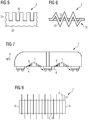
- FIG 3 is a sectional view of a bipolar plate 3 is shown, with a cutting direction parallel to the Electrode membrane units 2 runs.
- a plurality of cooling structures 32 are formed in the protruding region 31, which projects beyond a base body 33.
- the cooling structures 32 are formed by notches.
- the bipolar plate 3 thus has a reduced thickness in places in the protruding region 31.
- the Finns are in Figure 4 formed by elevations beyond the base body 33. That is, because of the cooling structures 32, the bipolar plate 3 in the protruding region 31 has a thickness that is greater than that of the base body 33 in places.
- the cooling structures 32 are formed by notches.
- the notches are produced, for example, by means of punching or cutting. It is possible for the protruding area 31 to have the same or a similar thickness as the base body 33.
- FIG 6 a plan view of an end face of a bipolar plate 3 is shown.
- the base body 33 is designed as a straight, flat plate.
- the fuel cell 1 has a wave-like structure in the protruding region 31.
- a vehicle 7 which comprises one or more of the fuel cells 1.
- the vehicle 7 is a train like a regional train.
- Cooling gas feeds 8 can optionally be provided from the surroundings of the vehicle 7 to the fuel cells 1.
- the cooling gas supply lines 8 are, for example, air ducts.
- the cooling gas feeds 8 flow around and cool the fuel cells 1 by means of air. This enables efficient air cooling of the fuel cells 1 with the aid of the protruding areas 31 on the bipolar plates 3.
- a cooling gas 4 which is formed by ambient air, thus flows through the cooling gas supply lines 8 to the fuel cells 1.
- fans or other ventilation devices can also be present, which in particular ensure sufficient cooling of the fuel cells 1 when the vehicle 7 is stationary.
- the power output of the fuel cells 1 while the vehicle 7 is stationary is generally significantly lower than while driving, so that additional cooling via an air flow by means of fans can optionally also be omitted entirely.
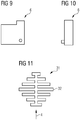
- connection 6 has a current collector 61, which preferably protrudes beyond the actual stack.
- gas port 62 which differs from Figure 9 two gas ports can also be provided. It is possible for a gas line to be looped through from the gas port 62 to the opposite connection 6 or to the most distant bipolar plate 3. The gas port 62 can protrude beyond the connection 6 in the direction away from the stack, not shown.
- FIG. 11 a further protrusion area 31 is illustrated.
- the cooling structures 32 are arranged in a flow-optimized manner and are designed as fins which are of different sizes.
- the cooling structures 32 can be arranged symmetrically to the respective central axes in the longitudinal direction and / or in the transverse direction.
- the cooling gas 4 flows in the plane of the drawing in FIG. 11 preferably from top to bottom or vice versa, but can also be guided perpendicular to the plane of the drawing.
- the arrangement of the cooling structures 32 of a protruding region 31, as in FIG Figure 11 shown, can also be transferred to the protruding areas 31 of several bipolar plates in the stack, so that the bipolar plates as a whole according to the structure in FIG Figure 11 can be arranged.
Landscapes
- Life Sciences & Earth Sciences (AREA)
- Engineering & Computer Science (AREA)
- Manufacturing & Machinery (AREA)
- Sustainable Development (AREA)
- Sustainable Energy (AREA)
- Chemical & Material Sciences (AREA)
- Chemical Kinetics & Catalysis (AREA)
- Electrochemistry (AREA)
- General Chemical & Material Sciences (AREA)
- Fuel Cell (AREA)
Description
- Es wird ein Betriebsverfahren für eine Brennstoffzelle angegeben.
- Die Druckschrift
EP 2 924 793 A1 betrifft eine Brennstoffzelle. - In der Druckschrift
EP 1 238 881 A1 ist ein Schienenfahrzeug angegeben. - Aus den Druckschriften
DE 10 2010 023 021 A1 ,JP 2010-061986 A US 2011/0281192 A1 undJP 2015-032477 A - Eine zu lösende Aufgabe liegt darin, ein Betriebsverfahren anzugeben, mit dem eine Brennstoffzelle effizient kühlbar ist.
- Diese Aufgabe wird durch ein Betriebsverfahren mit den Merkmalen des unabhängigen Patentanspruchs gelöst. Bevorzugte Weiterbildungen sind Gegenstand der abhängigen Ansprüche.
- Die Brennstoffzelle für das hier beschriebene Betriebsverfahren umfasst Bipolarplatten, die aus den übrigen Komponenten der Brennstoffzelle herausragen. Damit ist eine effiziente Kühlung der Brennstoffzelle über die Bipolarplatten möglich. Vorliegend fallen Endplatten einer Brennstoffzelle, welche einen Stapel mit der Elektroden-Membran-Einheit oder mit mehreren Elektroden-Membran-Einheiten und dazwischenliegenden Bipolarplatten begrenzen, der Einfachheit halber unter den Begriff Bipolarplatten, auch wenn es sich bei diesen in elektrischer Hinsicht aufgrund nur einer einzigen Polarität streng genommen nicht um Bipolarplatten handelt und insbesondere dahingehend modifiziert sein können.
- Die Brennstoffzelle umfasst mehrere Elektroden-Membran-Einheiten, auch als Membrane Electrode Assembly oder kurz MEA bezeichnet. Die Elektroden-Membran-Einheiten sind dazu eingerichtet, durch die Reaktion von Wasserstoff mit Sauerstoff zu Wasser elektrischen Strom zu erzeugen, sprich, sie sind dazu eingerichtet, die chemische Reaktionsenergie von Wasserstoff und Sauerstoff in elektrische Energie zu wandeln. Bevorzugt liegen die mehreren Eektroden-Membran-Einheiten über die Bipolarplatten elektrisch in Serie geschaltet vor. Bevorzugt liegen viele der Elektroden-Membran-Einheiten elektrisch in Serie geschaltet vor.
- Bevorzugt umfasst ein Trägergas den benötigten Wasserstoff. Der Wasserstoff wird aus dem Trägergas heraus umgesetzt. Bevorzugt umfasst das Trägergas den benötigten Wasserstoff. Bei dem Trägergas für Wasserstoff handelt es sich beispielsweise um Wasserstoffgas, kurz H2. Ebenso ist es möglich, dass als Trägergas für den Wasserstoff Erdgas und/oder Reformatgas dient.
- Der Sauerstoff für die Brennstoffzelle entstammt bevorzugt der Umgebungsluft, kann aber auch als reiner Sauerstoff zugeführt werden. Insbesondere ist es beispielsweise bei einem brennstoffzellenbetriebenen Zug möglich, dass der Sauerstoff zum Betreiben der Brennstoffzelle aus einer Luftleitung wie einer Hauptdruckluftleitung zum Betrieb von Bremsen des Zugs stammt.
Die Brennstoffzelle umfasst, abhängig von der Anzahl der Elektroden-Membran-Einheiten, mehr als zwei Bipolarplatten. Die mehreren Bipolarplatten befinden sich je zwischen benachbarten Elektroden-Membran-Einheiten. Über die Bipolarplatten ist eine elektrische Serienverschaltung der Elektroden-Membran-Einheiten gegeben. Die Elektroden-Membran-Einheiten und die Bipolarplatten liegen somit als Stapel, auch Stack genannt, vor. - Die Bipolarplatten dienen unter anderem bevorzugt dazu, die jeweils angrenzenden Elektroden-Membran-Einheiten mit mindestens einem Reaktionsgas zu versorgen, beispielsweise mit Wasserstoffgas und mit Luft. Die Trägergase für Wasserstoff und Sauerstoff werden getrennt voneinander geführt und befinden sich jeweils bevorzugt nur an einer Hauptseite einer Bipolarplatte. Das heißt, an der einen Seite der Bipolarplatte wird der einen angrenzenden Elektroden-Membran-Einheit Luft zugeführt, und an der anderen, der gegenüberliegenden Seite der Bipolarplattte wird der anderen angrenzenden Elektroden-Membran-Einheit H2-Gas zugeführt. Die Bipolarplatte ist mit entsprechenden Versorgungskanälen für die Gase ausgestattet.
- Die Bipolarplatten weisen einen Überstandbereich auf. Der Überstandbereich steht seitlich über die Elektroden-Membran-Einheiten über. Das heißt, der Überstandbereich ragt aus den übrigen Komponenten des Stapels mit den Elektroden-Membran-Einheiten, auch als Stack bezeichnet, hervor. Der Überstandbereich bildet damit einen Vorsprung oder eine Ausstülpung oder einen Sims an der Brennstoffzelle.
- Der Überstand ist dazu eingerichtet, von einem Kühlgas umströmt zu werden. Somit ist durch den Überstandbereich eine Kühlung der Brennstoffzelle über das Kühlgas ermöglicht. Brennstoffzellensysteme werden derzeit überwiegend durch externe Kühlaggregate gekühlt. Solche Kühlaggregate reduzieren den Gesamtwirkungsgrad des Brennstoffzellensystems. Bei der hier beschriebenen Brennstoffzelle werden Seiten der Bipolarplatten verlängert, sodass diese aus dem eigentlichen Stack herausstehen. Die modifizierten Bipolarplatten wirken somit als Kühlfinnen.
- Durch die Doppelfunktion der Bipolarplatte als Gaszufuhrplatte und als Kühlfinne kann auf ein externes Kühlaggregat verzichtet werden. Damit werden externe Kühlaggregate eingespart. Ein Gesamtwirkungsgrad wird erhöht. Ferner steht damit etwa auf einem Fahrzeug, auf dem sich die Brennstoffzelle befindet, mehr Bauraum anderweitig zur Verfügung, da auf ein Kühlaggregat verzichtet werden kann.
Gemäß zumindest einer Ausführungsform weisen die Bipolarplatten in dem Überstandbereich je mehrere Kühlstrukturen auf. Die Kühlstrukturen sind zum Beispiel durch Kühlfinnen, durch Einkerbungen und/oder durch Wellen gebildet. Der Begriff Welle bedeutet insbesondere, dass ein Grundkörper der Bipolarplatten in dem Überstandbereich verformt ist und in dem Überstandbereich beispielsweise ähnlich einem Wellblech geformt ist. - Gemäß zumindest einer Ausführungsform beträgt in Draufsicht längs einer Stapelrichtung der Elektroden-Membran-Einheiten gesehen eine Fläche des Überstandbereichs mindestens 5 % oder mindestens 10 % oder mindestens 20 % einer Grundfläche der Elektroden-Membran-Einheiten. Alternativ oder zusätzlich liegt die Fläche des Überstandbereichs bei höchstens 100 % oder höchstens 70 % oder höchstens 50 % der Grundfläche der Elektroden-Membran-Einheiten.
- Die Brennstoffzelle umfasst somit mehrere der Bipolarplatten, die jeweils zwischen benachbarten Elektroden-Membran-Einheiten angeordnet sind.
- Die Bipolarplatten stehen entlang einer Stapelrichtung der Elektroden-Membran-Einheiten im Querschnitt senkrecht zu den Elektroden-Membran-Einheiten insbesondere abwechselnd unterschiedlich weit über die Elektroden-Membran-Einheiten über. Mit anderen Worten überragen die Bipolarplatten die Elektroden-Membran-Einheiten verschieden weit, beispielsweise alternierend. Ein Überstand der Bipolarplatten über die Elektroden-Membran-Einheiten kann entlang der Stapelrichtung auch zuerst zunehmen und dann wieder abnehmen, sodass sich ein dreieckförmiges oder trapezförmiges Profil mit einem größten Überstand insbesondere in der Mitte des Stapels ergibt. Dadurch kann erzielt werden, dass ein Abstand zwischen benachbarten Überstandbereichen vergrößert ist. Somit kann ein Strömungsverhalten des Kühlgases um die Überstandbereiche herum eingestellt werden, wodurch sich ein Kühlverhalten verbessern kann.
- Gemäß zumindest einer Ausführungsform umfassen die Bipolarplatten eines oder mehrere der folgenden Materialien oder besteht oder bestehen aus einem oder mehreren der folgenden Materialien: Edelstahl, Graphit, Aluminium, Titan, Graphit-Compound-Thermoplast.
- Ein Graphit-Compound-Thermoplast ist ein thermoplastischer Kunststoff wie Polypropylen, der einen hohen Gewichtsanteil an Graphit aufweist. Der Graphit-Gewichtsanteil liegt beispielsweise bei mindestens 70 % oder mindestens 80 % oder mindestens 90 %. Ein Graphit-Compound-Thermoplast ist als Material für die mindestens eine Bipolarplatte besonders bevorzugt.
Gemäß zumindest einer Ausführungsform liegt eine Dicke der Bipolarplatten in dem Überstandbereich oder insgesamt bei mindestens 1 mm und/oder bei höchstens 10 mm oder 5 mm. - Gemäß zumindest einer Ausführungsform ist die Brennstoffzelle für einen trockenen Betrieb eingerichtet. Das heißt, im bestimmungsgemäßen Gebrauch kommt die Brennstoffzelle mit keinen Flüssigkeiten in Berührung. Somit werden sowohl der Sauerstoff als auch der Wasserstoff für die Gewinnung der Elektrizität in der Brennstoffzelle über Gase zugeführt. Außerdem erfolgt eine Kühlung ohne den Einsatz von Kühlflüssigkeiten, sondern ausschließlich über Gase oder Wärmeableitung.
- Gemäß dem Betriebsverfahren wird der Überstandbereich der Bipolarplatten luftgekühlt. Das heißt, bei dem Kühlgas handelt es sich um Luft. Die Luft kann turbulent und/oder laminar über den zumindest einen Überstandbereich hinweggeführt werden.
- Die Brennstoffzelle ist in einem Fahrzeug verbaut. Bei dem Fahrzeug handelt es sich um einen Zug wie einen Regionalzug, auch als Commuter Train bezeichnet.
- Eine bestimmungsgemäße Maximalleistung der Brennstoffzelle liegt bei mindestens 100 kW oder mindestens 150 kW. Alternativ oder zusätzlich liegt die Maximalleistung der Brennstoffzelle bei höchstens 1 MW oder höchstens 500 kW oder höchstens 300 kW. Die Maximalleistung bezieht sich auf eine elektrische Leistungsabgabe der Brennstoffzelle.
- Die Brennstoffzelle wird zeitweilig oder dauerhaft durch einen Fahrtwind gekühlt. Das heißt, durch die Fahrgeschwindigkeit des Fahrzeugs wird der Fahrtwind erzeugt und dieser umströmt die Brennstoffzelle zum Kühlen derselben oder liefert einen Strömungsdruck, sodass die Brennstoffzelle umströmt wird.
- Nachfolgend werden ein hier beschriebenes Betriebsverfahren und Brennstoffzellen hierfür unter Bezugnahme auf die Zeichnung anhand von Ausführungsbeispielen näher erläutert. Gleiche Bezugszeichen in den verschiedenen Figuren geben dabei jeweils gleiche oder gleich wirkende Elemente an. Es sind dabei jedoch keine maßstäblichen Bezüge dargestellt, vielmehr können einzelne Elemente zum besseren Verständnis übertrieben groß dargestellt sein.
- Es zeigen:
- Figuren 1, 2 und 8
- schematische Schnittdarstellungen von Brennstoffzellen,
- Figuren 3 und 4
- schematische Schnittdarstellungen von Bipolarplatten für Brennstoffzellen,
- Figur 5
- eine schematische Seitenansicht auf eine Bipolarplatte für Brennstoffzellen,
- Figur 6
- eine schematische Stirnseitenansicht auf eine Bipolarplatte für Brennstoffzelle,
- Figur 7
- eine schematische Schnittdarstellung eines hier beschriebenen Betriebsverfahrens für eine Brennstoffzelle in einem Zug,
- Figur 9
- eine schematische Draufsicht auf einen elektrischen Anschluss für eine Brennstoffzelle,
- Figur 10
- eine schematische Seitenansicht auf einen elektrischen Anschluss für eine Brennstoffzelle, und
- Figur 11
- eine schematische Seitenansicht auf eine Bipolarplatte für Brennstoffzellen.
- In
Figur 1 ist eine Brennstoffzelle 1 dargestellt. Zwischen elektrischen Anschlüssen 6 befinden sich mehrere Elektroden-Membran-Einheiten 2. Bevorzugt sind die Elektroden der Elektroden-Membran-Einheiten 2 jeweils durch Gasdiffusionsschichten 5 gebildet. Zum Beispiel sind mindestens 15 und/oder höchstens 10 der Elektroden-Membran-Einheiten 2 vorhanden. - Zwischen benachbarten Elektroden-Membran-Einheiten 2 befinden sich jeweils Bipolarplatten 3. Über die Bipolarplatten 3 erfolgt eine elektrische Serienschaltung der Elektroden-Membran-Einheiten 2 sowie deren Versorgung mit Reaktionsgasen für Sauerstoff und Wasserstoff. Die Gasversorgung ist in den Figuren zur Vereinfachung der Darstellung nicht gezeichnet. Die Bipolarplatten 3 bilden zusammen mit den Elektroden-Membran-Einheiten 2 einen Stapel, auch als Stack bezeichnet. Beispielsweise sind die Bipolarplatten 3 aus einem Graphit-Compound-Thermoplast und weisen zum Beispiel eine Dicke von ungefähr 3 mm auf.
- Die Bipolarplatten 3 ragen über die anderen Komponenten der Brennstoffzelle 2 hinaus. Dadurch wirken die Bipolarplatten 3 als Wärmeableiter und als Kühlfinnen. Somit ist eine effiziente Kühlung der Brennstoffzelle über die Bipolarplatten 3 ermöglicht.
- An den elektrischen Anschlüssen 6, die Endteile des Stacks sind, erfolgt ein Abgriff des Stroms, der in der Brennstoffzelle 1 erzeugt wird. Die Anschlüsse 6 können jeweils durch eine Bipolarplatte 3 oder durch eine modifizierte Bipolarplatte 3 gebildet sein. Weiterhin kann durch die Anschlüsse 6 hindurch jeweils eine Versorgung der nächstgelegenen Elektroden-Membran-Einheit mit einem Reaktionsgas, nicht gezeichnet, erfolgen.
- Ein Überstandbereich 31 der Bipolarplatten 3, der verbleibende Komponenten der Brennstoffzelle 1 jeweils überragt, weist beispielsweise eine Fläche von ungefähr 25 % einer Grundfläche der Elektroden-Membran-Einheiten 2 auf.
- In
Figur 2 ist gezeigt, dass die elektrischen Anschlüsse 6 genauso wie die Bipolarplatten 3 als Kühlkörper gestaltet sein können, der die übrigen Komponenten der Brennstoffzelle 1 überragt. Wie auch inFigur 1 können die Anschlüsse 6 durch Bipolarplatten 3 oder durch modifizierte Bipolarplatten 3 gebildet sein. Ein Überstandbereich 31 der Anschlüsse 6 kann genauso groß sein wie an den Bipolarplatten 3. Abweichend von der Darstellung inFigur 2 können die Überstandbereiche 31 der Anschlüsse 6 und der Bipolarplatten 3 auch unterschiedlich groß gestaltet sein. - In
Figur 3 ist eine Schnittdarstellung einer Bipolarplatte 3 dargestellt, wobei eine Schnittrichtung parallel zu den Elektroden-Membran-Einheiten 2 verläuft. GemäßFigur 3 sind in dem Überstandbereich 31, der einen Grundkörper 33 überragt, mehrere Kühlstrukturen 32 geformt. Die Kühlstrukturen 32 sind durch Einkerbungen gebildet. Somit weist die Bipolarplatte 3 in dem Überstandbereich 31 stellenweise eine reduzierte Dicke auf. - Demgegenüber sind die Finnen in
Figur 4 durch Erhebungen über den Grundkörper 33 hinaus gebildet. Das heißt, aufgrund der Kühlstrukturen 32 weist die Bipolarplatte 3 in dem Überstandbereich 31 stellenweise eine gegenüber dem Grundkörper 33 vergrößerte Dicke auf. - In der Seitenansicht der Bipolarplatte 3 der
Figur 5 ist zu sehen, dass die Kühlstrukturen 32 durch Einkerbungen gebildet sind. Die Einkerbungen sind zum Beispiel mittels Stanzen oder Schneiden erzeugt. Es ist möglich, dass der Überstandbereich 31 die gleiche oder eine ähnliche Dicke aufweist wie der Grundkörper 33. - In
Figur 6 ist eine Aufsicht auf eine Stirnseite einer Bipolarplatte 3 gezeigt. Der Grundkörper 33 ist als gerade, ebene Platte gestaltet. Demgegenüber weist die Brennstoffzelle 1 in dem Überstandbereich 31 eine wellenartige Struktur auf. Die Wellen, zu denen die Bipolarplatte 3 in den Überstandbereich 31 beispielsweise über Biegen, Stanzen und/oder Pressen geformt ist, bilden die Kühlstrukturen 32. - In
Figur 7 ist ein Fahrzeug 7 dargestellt, das eine oder mehrere der Brennstoffzellen 1 umfasst. Das Fahrzeug 7 ist ein Zug wie ein Regionalzug. - Optional können von einer Umgebung des Fahrzeugs 7 hin zu den Brennstoffzellen 1 jeweils Kühlgaszuführungen 8 vorhanden sein. Die Kühlgaszuführungen 8 sind beispielsweise Luftkanäle. Alternativ ist es möglich, dass die Brennstoffzellen 1, anders als in
Figur 7 gezeichnet, über einen Basiskörper des Fahrzeugs 7 hinausragen und damit unmittelbar einer Umgebungsluft ausgesetzt sind. - Wird das Fahrzeug 7 betrieben, bewegt es sich entlang einer Fahrtrichtung 9. Aufgrund eines Fahrtwindes erfolgt dann beispielsweise über die Kühlgaszuführungen 8 eine Umströmung und einhergehend eine Kühlung der Brennstoffzellen 1 mittels Luft. Damit ist eine effiziente Luftkühlung der Brennstoffzellen 1 mit Hilfe der Überstandbereiche 31 an den Bipolarplatten 3 ermöglicht.
- Durch die Kühlgaszuführungen 8 strömt somit ein Kühlgas 4, das durch Umgebungsluft gebildet ist, zu den Brennstoffzellen 1. Damit kann während der Fahrt des Fahrzeugs 7 ein hoher Luftumsatz und eine ausreichende Luftumströmung an den Brennstoffzellen 1 sichergestellt werden.
- Alternativ oder zusätzlich zu Kühlgaszuführungen 8 können auch Ventilatoren oder andere Belüftungseinrichtungen vorhanden sein, die insbesondere eine ausreichende Kühlung der Brennstoffzellen 1 gewährleisten, wenn das Fahrzeug 7 steht. Andererseits ist die Leistungsabgabe der Brennstoffzellen 1 während des Stehens des Fahrzeugs 7 im Regelfall deutlich niedriger als während der Fahrt, sodass eine zusätzliche Kühlung über einen Luftstrom mittels Ventilatoren optional auch gänzlich entfallen kann.
- In
Figur 8 ist illustriert, dass die Bipolarplatten 3 abwechselnd unterschiedlich weit über die verbleibenden Komponenten der Brennstoffzelle 1 hinausragen. Damit können benachbarte Überstandbereiche 31 einen größeren Abstand zueinander aufweisen. Hierdurch kann eine effizientere Umströmung mit einem Kühlgas 4 wie Luft erreicht werden. - In den
Figuren 9 und 10 ist ein elektrischer Anschluss 6 gezeigt. Der Anschluss 6 weist einen Stromabnehmer 61 auf, der bevorzugt über den eigentlichen Stack übersteht. Zudem ist ein Gasport 62 vorhanden, wobei abweichend vonFigur 9 auch zwei Gasports vorgesehen sein können. Es ist möglich, dass eine Gasleitung von dem Gasport 62 her bis zum gegenüberliegenden Anschluss 6 oder bis zur am weitesten entfernten Bipolarplatte 3 durchgeschleift wird. Der Gasport 62 kann den Anschluss 6 in Richtung weg von dem Stack, nicht gezeichnet, überragen. - In
Figur 11 ist ein weiterer Überstandbereichs 31 illustriert. Die Kühlstrukturen 32 sind strömungsoptimiert angeordnet und als Finnen gestaltet, die unterschiedlich groß sind. Die Kühlstrukturen 32 können in Längsrichtung und/oder in Querrichtung symmetrisch zu jeweiligen Mittelachsen angeordnet sein. Das Kühlgas 4 strömt in der Zeichenebene der Figur 11 bevorzugt von oben nach unten oder umgekehrt, kann aber auch senkrecht zur Zeichenebene geführt werden. - Die Anordnung der Kühlstrukturen 32 eines Überstandsbereichs 31, wie in
Figur 11 dargestellt, lässt sich auch auf die Überstandsbereiche 31 mehrerer Bipolarplatten in dem Stack übertragen, sodass die Bipolarplatten insgesamt gemäß der Struktur inFigur 11 angeordnet sein können. -
- 1
- Brennstoffzelle
- 2
- Elektroden-Membran-Einheit
- 3
- Bipolarplatte
- 31
- Überstandbereich
- 32
- Kühlstruktur
- 33
- Grundkörper
- 4
- Kühlgas
- 5
- Gasdiffusionsschicht
- 6
- elektrischer Anschluss
- 61
- Stromabnehmer
- 62
- Gasport
- 7
- Fahrzeug
- 8
- Kühlgaszuführung
- 9
- Fahrtrichtung
Claims (11)
- Betriebsverfahren für eine Brennstoffzelle (1) mit- mehreren Elektroden-Membran-Einheiten (2),- mehreren Bipolarplatten (3),wobei- die Bipolarplatten (3) je zwischen zwei benachbarten Elektroden-Membran-Einheiten (2) angeordnet sind,- entlang einer Stapelrichtung der Elektroden-Membran-Einheiten (2) im Querschnitt längs der Stapelrichtung gesehen, die Bipolarplatten (3) in einem Überstandbereich (31) unterschiedlich weit über die Elektroden-Membran-Einheiten (2) überstehen,- der Überstandbereich (31) dazu eingerichtet ist, von einem Kühlgas (4), das Luft ist, umströmt zu werden, sodass der Überstandbereich (31) der Bipolarplatten (3) luftgekühlt wird,- die Brennstoffzelle (1) in einem Zug (7) verbaut ist,- eine Maximalleistung der Brennstoffzelle (1) mindestens 100 kW beträgt, und- von einer Umgebung des Zugs (7) hin zu der Brennstoffzelle (1) eine Kühlgaszuführung (8) vorhanden ist, die ein Luftkanal ist, sodass die Brennstoffzelle (1) durch einen Fahrtwind gekühlt wird.
- Betriebsverfahren nach dem vorhergehenden Anspruch,
wobei die Bipolarplatten (3) im Überstandbereich (31) jeweils Kühlstrukturen (32) aufweisen. - Betriebsverfahren nach dem vorhergehenden Anspruch,
wobei die Kühlstrukturen (32) durch Kühlfinnen, Einkerbungen und/oder Wellen gebildet sind. - Betriebsverfahren nach einem der vorhergehenden Ansprüche,
wobei ein Fläche des Überstandbereichs (31) in Draufsicht auf diesen gesehen zwischen einschließlich 10 % und einschließlich 50 % einer Grundfläche der Elektroden-Membran-Einheiten (2) beträgt. - Betriebsverfahren nach einem der vorhergehenden Ansprüche,
wobei entlang der Stapelrichtung der Elektroden-Membran-Einheiten (2) im Querschnitt längs der Stapelrichtung gesehen die Bipolarplatten (3) abwechselnd unterschiedlich weit über die Elektroden-Membran-Einheiten (2) überstehen. - Betriebsverfahren nach einem der Ansprüche 1 bis 4,
wobei ein Überstand der Bipolarplatten (3) über die Elektroden-Membran-Einheiten (2) entlang der Stapelrichtung zuerst zunimmt und dann wieder abnimmt, sodass sich ein dreieckförmiges oder trapezförmiges Profil mit einem größten Überstand in einer Mitte eines Stapels der Bipolarplatten (3) und der Elektroden-Membran-Einheiten (2) ergibt. - Betriebsverfahren nach einem der vorhergehenden Ansprüche,
wobei mindestens eine der Bipolarplatten (3) eines oder mehrere der folgenden Materialien umfasst oder aus einem oder mehreren der folgenden Materialien ist: Edelstahl, Graphit, Aluminium, Titan, Graphit-Compound-Thermoplast. - Betriebsverfahren nach einem der vorhergehenden Ansprüche,
wobei eine Dicke der Bipolarplatten (3) in dem Überstandbereich (31) bei mindestens 1 mm und bei höchstens 10 mm liegt. - Betriebsverfahren nach einem der vorhergehenden Ansprüche,
wobei die Brennstoffzelle (1) ausschließlich für einen trockenen Betrieb eingerichtet ist, sodass keine Flüssigkeitskühlung vorgesehen ist. - Betriebsverfahren nach einem der vorherigen Ansprüche,
wobei keine zusätzliche Kühlung vorhanden ist, sodass eine Kühlung der Brennstoffzelle (1) ausschließlich aufgrund des Fahrtwinds erfolgt. - Betriebsverfahren nach einem der vorhergehenden Ansprüche,
wobei- mehrere Brennstoffzellen (1) in dem Fahrzeug (7) verbaut sind, und- die Bipolarplatten (3) auch dazu dienen, die jeweils angrenzenden Elektroden-Membran-Einheiten (2) mit mindestens einem Reaktionsgas zu versorgen, sodass die Bipolarplatten (3) eine Doppelfunktion als Gaszufuhrplatte und als Kühlfinne aufweisen.
Applications Claiming Priority (1)
| Application Number | Priority Date | Filing Date | Title |
|---|---|---|---|
| DE102018211982.1A DE102018211982A1 (de) | 2018-07-18 | 2018-07-18 | Brennstoffzelle und Betriebsverfahren für eine Brennstoffzelle |
Publications (2)
| Publication Number | Publication Date |
|---|---|
| EP3598548A1 EP3598548A1 (de) | 2020-01-22 |
| EP3598548B1 true EP3598548B1 (de) | 2021-02-03 |
Family
ID=67297033
Family Applications (1)
| Application Number | Title | Priority Date | Filing Date |
|---|---|---|---|
| EP19186257.2A Not-in-force EP3598548B1 (de) | 2018-07-18 | 2019-07-15 | Betriebsverfahren für eine brennstoffzelle |
Country Status (4)
| Country | Link |
|---|---|
| EP (1) | EP3598548B1 (de) |
| CN (1) | CN110739469B (de) |
| DE (1) | DE102018211982A1 (de) |
| DK (1) | DK3598548T3 (de) |
Families Citing this family (1)
| Publication number | Priority date | Publication date | Assignee | Title |
|---|---|---|---|---|
| DE102023112965B4 (de) * | 2023-05-17 | 2025-03-27 | Schaeffler Technologies AG & Co. KG | Verfahren zur Herstellung einer Bipolarplatte und Bipolarplatte |
Family Cites Families (9)
| Publication number | Priority date | Publication date | Assignee | Title |
|---|---|---|---|---|
| DE10110424A1 (de) | 2001-03-05 | 2002-09-12 | Siemens Duewag Gmbh | Angetriebenes Schienenfahrzeug, insbesondere für die Personenbeförderung im Nah- und Regionalverkehr |
| DE102005031081A1 (de) * | 2005-06-27 | 2006-12-28 | Deutsches Zentrum für Luft- und Raumfahrt e.V. | Bipolarplatte, Verfahren zur Herstellung einer Bipolarplatte und Brennstoffzellenblock-Anordnung |
| CN101308936A (zh) * | 2008-06-03 | 2008-11-19 | 大连工业大学 | 空气直接冷却的燃料电池 |
| JP2010061986A (ja) * | 2008-09-03 | 2010-03-18 | Toshiba Corp | 燃料電池スタック |
| US8470489B2 (en) * | 2010-05-13 | 2013-06-25 | Energyor Technologies Inc. | Method for producing bipolar plates |
| DE102010023021A1 (de) * | 2010-06-08 | 2011-12-08 | Enymotion Gmbh | Brennstoffzelle mit einem Stack aus mehreren Bipolarplatten |
| JP6053633B2 (ja) * | 2013-08-02 | 2016-12-27 | 株式会社日本自動車部品総合研究所 | 燃料電池セルスタック |
| EP2924793A1 (de) | 2014-03-24 | 2015-09-30 | Siemens Aktiengesellschaft | Brennstoffzelle mit verbessertem Wärmehaushalt |
| CN106129435A (zh) * | 2016-08-10 | 2016-11-16 | 大连融科储能技术发展有限公司 | 一种液流电池换热装置 |
-
2018
- 2018-07-18 DE DE102018211982.1A patent/DE102018211982A1/de not_active Ceased
-
2019
- 2019-07-15 EP EP19186257.2A patent/EP3598548B1/de not_active Not-in-force
- 2019-07-15 DK DK19186257.2T patent/DK3598548T3/da active
- 2019-07-16 CN CN201910639446.1A patent/CN110739469B/zh not_active Expired - Fee Related
Non-Patent Citations (1)
| Title |
|---|
| None * |
Also Published As
| Publication number | Publication date |
|---|---|
| CN110739469A (zh) | 2020-01-31 |
| CN110739469B (zh) | 2023-07-28 |
| DK3598548T3 (da) | 2021-04-12 |
| EP3598548A1 (de) | 2020-01-22 |
| DE102018211982A1 (de) | 2020-01-23 |
Similar Documents
| Publication | Publication Date | Title |
|---|---|---|
| EP1830426B1 (de) | Bipolarplatte, insbesondere für einen Brennstoffzellenstapel eines Fahrzeugs | |
| EP3631884B1 (de) | Separatorplatte für ein elektrochemisches system | |
| EP0876686B1 (de) | Flüssigkeitsgekühlte brennstoffzelle mit verteilungskanälen | |
| DE102015224994A1 (de) | Bipolarplattenstruktur für Brennstoffzellen | |
| DE102011118817A1 (de) | Brennstoffzellen-separatorplatte | |
| WO2019229138A1 (de) | Separatorplatte für ein elektrochemisches system | |
| DE112012007187B4 (de) | Temperaturregulierungsstruktur für Energiespeicherelement | |
| DE102019200084A1 (de) | Stromerzeugungszelle | |
| DE202020106459U1 (de) | Anordnung für ein elektrochemisches System, Stapel sowie elektrochemisches System | |
| DE102017125928B4 (de) | Brennstoffzelle mit verbessertem Wassermanagement | |
| DE102013206317A1 (de) | Brennstoffzellenstapel | |
| DE102008056900A1 (de) | Bipolarplatte für eine Brennstoffzellenanordnung, insbesondere zur Anordnung zwischen zwei benachbarten Membran-Elektroden-Anordnungen in einem Brennstoffzellenstapel | |
| DE102016212785A1 (de) | Brennstoffzellenstapel | |
| DE102014208644A1 (de) | Brennstoffzellenseparator und Brennstoffzellenstapel mit demselben | |
| DE202019101145U1 (de) | Separatorplatte für ein elektrochemisches System | |
| DE102014206333A1 (de) | Bipolarplatte sowie Brennstoffzelle mit einer solchen | |
| DE202022101861U1 (de) | Separatorplatte | |
| EP3598548B1 (de) | Betriebsverfahren für eine brennstoffzelle | |
| WO2010083788A1 (de) | Wiederholeinheit für einen brennstoffzellenstapel | |
| DE102010023021A1 (de) | Brennstoffzelle mit einem Stack aus mehreren Bipolarplatten | |
| DE102014224873A1 (de) | Brennstoffzellenstapel | |
| DE202021106642U1 (de) | Separatorplatte mit Schweißabschnitten | |
| DE102014216203B4 (de) | Brennstoffzelle für ein fahrzeug | |
| DE102006056468A1 (de) | Bipolarplatte, insbesondere für einen Brennstoffzellenstapel eines Fahrzeugs | |
| DE102020208942A1 (de) | Brennstoffzellenstapel mit unterbrochenen Bipolarplatten |
Legal Events
| Date | Code | Title | Description |
|---|---|---|---|
| PUAI | Public reference made under article 153(3) epc to a published international application that has entered the european phase |
Free format text: ORIGINAL CODE: 0009012 |
|
| STAA | Information on the status of an ep patent application or granted ep patent |
Free format text: STATUS: THE APPLICATION HAS BEEN PUBLISHED |
|
| AK | Designated contracting states |
Kind code of ref document: A1 Designated state(s): AL AT BE BG CH CY CZ DE DK EE ES FI FR GB GR HR HU IE IS IT LI LT LU LV MC MK MT NL NO PL PT RO RS SE SI SK SM TR |
|
| AX | Request for extension of the european patent |
Extension state: BA ME |
|
| STAA | Information on the status of an ep patent application or granted ep patent |
Free format text: STATUS: REQUEST FOR EXAMINATION WAS MADE |
|
| 17P | Request for examination filed |
Effective date: 20200720 |
|
| RBV | Designated contracting states (corrected) |
Designated state(s): AL AT BE BG CH CY CZ DE DK EE ES FI FR GB GR HR HU IE IS IT LI LT LU LV MC MK MT NL NO PL PT RO RS SE SI SK SM TR |
|
| GRAP | Despatch of communication of intention to grant a patent |
Free format text: ORIGINAL CODE: EPIDOSNIGR1 |
|
| STAA | Information on the status of an ep patent application or granted ep patent |
Free format text: STATUS: GRANT OF PATENT IS INTENDED |
|
| INTG | Intention to grant announced |
Effective date: 20200923 |
|
| GRAS | Grant fee paid |
Free format text: ORIGINAL CODE: EPIDOSNIGR3 |
|
| GRAA | (expected) grant |
Free format text: ORIGINAL CODE: 0009210 |
|
| STAA | Information on the status of an ep patent application or granted ep patent |
Free format text: STATUS: THE PATENT HAS BEEN GRANTED |
|
| AK | Designated contracting states |
Kind code of ref document: B1 Designated state(s): AL AT BE BG CH CY CZ DE DK EE ES FI FR GB GR HR HU IE IS IT LI LT LU LV MC MK MT NL NO PL PT RO RS SE SI SK SM TR |
|
| REG | Reference to a national code |
Ref country code: GB Ref legal event code: FG4D Free format text: NOT ENGLISH |
|
| REG | Reference to a national code |
Ref country code: CH Ref legal event code: EP Ref country code: AT Ref legal event code: REF Ref document number: 1359891 Country of ref document: AT Kind code of ref document: T Effective date: 20210215 |
|
| REG | Reference to a national code |
Ref country code: DE Ref legal event code: R096 Ref document number: 502019000778 Country of ref document: DE |
|
| REG | Reference to a national code |
Ref country code: IE Ref legal event code: FG4D Free format text: LANGUAGE OF EP DOCUMENT: GERMAN |
|
| REG | Reference to a national code |
Ref country code: DK Ref legal event code: T3 Effective date: 20210408 |
|
| REG | Reference to a national code |
Ref country code: NL Ref legal event code: MP Effective date: 20210203 |
|
| REG | Reference to a national code |
Ref country code: LT Ref legal event code: MG9D |
|
| PG25 | Lapsed in a contracting state [announced via postgrant information from national office to epo] |
Ref country code: LT Free format text: LAPSE BECAUSE OF FAILURE TO SUBMIT A TRANSLATION OF THE DESCRIPTION OR TO PAY THE FEE WITHIN THE PRESCRIBED TIME-LIMIT Effective date: 20210203 Ref country code: NO Free format text: LAPSE BECAUSE OF FAILURE TO SUBMIT A TRANSLATION OF THE DESCRIPTION OR TO PAY THE FEE WITHIN THE PRESCRIBED TIME-LIMIT Effective date: 20210503 Ref country code: PT Free format text: LAPSE BECAUSE OF FAILURE TO SUBMIT A TRANSLATION OF THE DESCRIPTION OR TO PAY THE FEE WITHIN THE PRESCRIBED TIME-LIMIT Effective date: 20210604 Ref country code: FI Free format text: LAPSE BECAUSE OF FAILURE TO SUBMIT A TRANSLATION OF THE DESCRIPTION OR TO PAY THE FEE WITHIN THE PRESCRIBED TIME-LIMIT Effective date: 20210203 Ref country code: GR Free format text: LAPSE BECAUSE OF FAILURE TO SUBMIT A TRANSLATION OF THE DESCRIPTION OR TO PAY THE FEE WITHIN THE PRESCRIBED TIME-LIMIT Effective date: 20210504 Ref country code: HR Free format text: LAPSE BECAUSE OF FAILURE TO SUBMIT A TRANSLATION OF THE DESCRIPTION OR TO PAY THE FEE WITHIN THE PRESCRIBED TIME-LIMIT Effective date: 20210203 Ref country code: BG Free format text: LAPSE BECAUSE OF FAILURE TO SUBMIT A TRANSLATION OF THE DESCRIPTION OR TO PAY THE FEE WITHIN THE PRESCRIBED TIME-LIMIT Effective date: 20210503 |
|
| PG25 | Lapsed in a contracting state [announced via postgrant information from national office to epo] |
Ref country code: NL Free format text: LAPSE BECAUSE OF FAILURE TO SUBMIT A TRANSLATION OF THE DESCRIPTION OR TO PAY THE FEE WITHIN THE PRESCRIBED TIME-LIMIT Effective date: 20210203 Ref country code: LV Free format text: LAPSE BECAUSE OF FAILURE TO SUBMIT A TRANSLATION OF THE DESCRIPTION OR TO PAY THE FEE WITHIN THE PRESCRIBED TIME-LIMIT Effective date: 20210203 Ref country code: PL Free format text: LAPSE BECAUSE OF FAILURE TO SUBMIT A TRANSLATION OF THE DESCRIPTION OR TO PAY THE FEE WITHIN THE PRESCRIBED TIME-LIMIT Effective date: 20210203 Ref country code: RS Free format text: LAPSE BECAUSE OF FAILURE TO SUBMIT A TRANSLATION OF THE DESCRIPTION OR TO PAY THE FEE WITHIN THE PRESCRIBED TIME-LIMIT Effective date: 20210203 Ref country code: SE Free format text: LAPSE BECAUSE OF FAILURE TO SUBMIT A TRANSLATION OF THE DESCRIPTION OR TO PAY THE FEE WITHIN THE PRESCRIBED TIME-LIMIT Effective date: 20210203 |
|
| PG25 | Lapsed in a contracting state [announced via postgrant information from national office to epo] |
Ref country code: IS Free format text: LAPSE BECAUSE OF FAILURE TO SUBMIT A TRANSLATION OF THE DESCRIPTION OR TO PAY THE FEE WITHIN THE PRESCRIBED TIME-LIMIT Effective date: 20210603 |
|
| PG25 | Lapsed in a contracting state [announced via postgrant information from national office to epo] |
Ref country code: EE Free format text: LAPSE BECAUSE OF FAILURE TO SUBMIT A TRANSLATION OF THE DESCRIPTION OR TO PAY THE FEE WITHIN THE PRESCRIBED TIME-LIMIT Effective date: 20210203 Ref country code: SM Free format text: LAPSE BECAUSE OF FAILURE TO SUBMIT A TRANSLATION OF THE DESCRIPTION OR TO PAY THE FEE WITHIN THE PRESCRIBED TIME-LIMIT Effective date: 20210203 |
|
| REG | Reference to a national code |
Ref country code: DE Ref legal event code: R097 Ref document number: 502019000778 Country of ref document: DE |
|
| PG25 | Lapsed in a contracting state [announced via postgrant information from national office to epo] |
Ref country code: RO Free format text: LAPSE BECAUSE OF FAILURE TO SUBMIT A TRANSLATION OF THE DESCRIPTION OR TO PAY THE FEE WITHIN THE PRESCRIBED TIME-LIMIT Effective date: 20210203 Ref country code: SK Free format text: LAPSE BECAUSE OF FAILURE TO SUBMIT A TRANSLATION OF THE DESCRIPTION OR TO PAY THE FEE WITHIN THE PRESCRIBED TIME-LIMIT Effective date: 20210203 |
|
| PLBE | No opposition filed within time limit |
Free format text: ORIGINAL CODE: 0009261 |
|
| STAA | Information on the status of an ep patent application or granted ep patent |
Free format text: STATUS: NO OPPOSITION FILED WITHIN TIME LIMIT |
|
| 26N | No opposition filed |
Effective date: 20211104 |
|
| PG25 | Lapsed in a contracting state [announced via postgrant information from national office to epo] |
Ref country code: AL Free format text: LAPSE BECAUSE OF FAILURE TO SUBMIT A TRANSLATION OF THE DESCRIPTION OR TO PAY THE FEE WITHIN THE PRESCRIBED TIME-LIMIT Effective date: 20210203 Ref country code: ES Free format text: LAPSE BECAUSE OF FAILURE TO SUBMIT A TRANSLATION OF THE DESCRIPTION OR TO PAY THE FEE WITHIN THE PRESCRIBED TIME-LIMIT Effective date: 20210203 |
|
| PG25 | Lapsed in a contracting state [announced via postgrant information from national office to epo] |
Ref country code: SI Free format text: LAPSE BECAUSE OF FAILURE TO SUBMIT A TRANSLATION OF THE DESCRIPTION OR TO PAY THE FEE WITHIN THE PRESCRIBED TIME-LIMIT Effective date: 20210203 |
|
| PG25 | Lapsed in a contracting state [announced via postgrant information from national office to epo] |
Ref country code: MC Free format text: LAPSE BECAUSE OF FAILURE TO SUBMIT A TRANSLATION OF THE DESCRIPTION OR TO PAY THE FEE WITHIN THE PRESCRIBED TIME-LIMIT Effective date: 20210203 |
|
| REG | Reference to a national code |
Ref country code: BE Ref legal event code: MM Effective date: 20210731 |
|
| PG25 | Lapsed in a contracting state [announced via postgrant information from national office to epo] |
Ref country code: IT Free format text: LAPSE BECAUSE OF FAILURE TO SUBMIT A TRANSLATION OF THE DESCRIPTION OR TO PAY THE FEE WITHIN THE PRESCRIBED TIME-LIMIT Effective date: 20210203 |
|
| PG25 | Lapsed in a contracting state [announced via postgrant information from national office to epo] |
Ref country code: IS Free format text: LAPSE BECAUSE OF FAILURE TO SUBMIT A TRANSLATION OF THE DESCRIPTION OR TO PAY THE FEE WITHIN THE PRESCRIBED TIME-LIMIT Effective date: 20210603 Ref country code: LU Free format text: LAPSE BECAUSE OF NON-PAYMENT OF DUE FEES Effective date: 20210715 |
|
| PG25 | Lapsed in a contracting state [announced via postgrant information from national office to epo] |
Ref country code: IE Free format text: LAPSE BECAUSE OF NON-PAYMENT OF DUE FEES Effective date: 20210715 Ref country code: BE Free format text: LAPSE BECAUSE OF NON-PAYMENT OF DUE FEES Effective date: 20210731 |
|
| REG | Reference to a national code |
Ref country code: CH Ref legal event code: PL |
|
| PG25 | Lapsed in a contracting state [announced via postgrant information from national office to epo] |
Ref country code: LI Free format text: LAPSE BECAUSE OF NON-PAYMENT OF DUE FEES Effective date: 20220731 Ref country code: CH Free format text: LAPSE BECAUSE OF NON-PAYMENT OF DUE FEES Effective date: 20220731 |
|
| PG25 | Lapsed in a contracting state [announced via postgrant information from national office to epo] |
Ref country code: CY Free format text: LAPSE BECAUSE OF FAILURE TO SUBMIT A TRANSLATION OF THE DESCRIPTION OR TO PAY THE FEE WITHIN THE PRESCRIBED TIME-LIMIT Effective date: 20210203 |
|
| PG25 | Lapsed in a contracting state [announced via postgrant information from national office to epo] |
Ref country code: HU Free format text: LAPSE BECAUSE OF FAILURE TO SUBMIT A TRANSLATION OF THE DESCRIPTION OR TO PAY THE FEE WITHIN THE PRESCRIBED TIME-LIMIT; INVALID AB INITIO Effective date: 20190715 |
|
| PGFP | Annual fee paid to national office [announced via postgrant information from national office to epo] |
Ref country code: CZ Payment date: 20230711 Year of fee payment: 5 |
|
| PGFP | Annual fee paid to national office [announced via postgrant information from national office to epo] |
Ref country code: FR Payment date: 20230720 Year of fee payment: 5 Ref country code: DK Payment date: 20230721 Year of fee payment: 5 Ref country code: DE Payment date: 20230918 Year of fee payment: 5 |
|
| GBPC | Gb: european patent ceased through non-payment of renewal fee |
Effective date: 20230715 |
|
| PG25 | Lapsed in a contracting state [announced via postgrant information from national office to epo] |
Ref country code: MK Free format text: LAPSE BECAUSE OF FAILURE TO SUBMIT A TRANSLATION OF THE DESCRIPTION OR TO PAY THE FEE WITHIN THE PRESCRIBED TIME-LIMIT Effective date: 20210203 Ref country code: GB Free format text: LAPSE BECAUSE OF NON-PAYMENT OF DUE FEES Effective date: 20230715 |
|
| PG25 | Lapsed in a contracting state [announced via postgrant information from national office to epo] |
Ref country code: TR Free format text: LAPSE BECAUSE OF FAILURE TO SUBMIT A TRANSLATION OF THE DESCRIPTION OR TO PAY THE FEE WITHIN THE PRESCRIBED TIME-LIMIT Effective date: 20210203 |
|
| PG25 | Lapsed in a contracting state [announced via postgrant information from national office to epo] |
Ref country code: MT Free format text: LAPSE BECAUSE OF FAILURE TO SUBMIT A TRANSLATION OF THE DESCRIPTION OR TO PAY THE FEE WITHIN THE PRESCRIBED TIME-LIMIT Effective date: 20210203 |
|
| REG | Reference to a national code |
Ref country code: DE Ref legal event code: R119 Ref document number: 502019000778 Country of ref document: DE |
|
| REG | Reference to a national code |
Ref country code: DK Ref legal event code: EBP Effective date: 20240731 |
|
| PG25 | Lapsed in a contracting state [announced via postgrant information from national office to epo] |
Ref country code: DE Free format text: LAPSE BECAUSE OF NON-PAYMENT OF DUE FEES Effective date: 20250201 |
|
| PG25 | Lapsed in a contracting state [announced via postgrant information from national office to epo] |
Ref country code: FR Free format text: LAPSE BECAUSE OF NON-PAYMENT OF DUE FEES Effective date: 20240731 Ref country code: CZ Free format text: LAPSE BECAUSE OF NON-PAYMENT OF DUE FEES Effective date: 20240715 |
|
| PG25 | Lapsed in a contracting state [announced via postgrant information from national office to epo] |
Ref country code: DK Free format text: LAPSE BECAUSE OF NON-PAYMENT OF DUE FEES Effective date: 20240731 |
|
| REG | Reference to a national code |
Ref country code: AT Ref legal event code: MM01 Ref document number: 1359891 Country of ref document: AT Kind code of ref document: T Effective date: 20240715 |
|
| PG25 | Lapsed in a contracting state [announced via postgrant information from national office to epo] |
Ref country code: AT Free format text: LAPSE BECAUSE OF NON-PAYMENT OF DUE FEES Effective date: 20240715 |
|
| PGFP | Annual fee paid to national office [announced via postgrant information from national office to epo] |
Ref country code: AT Payment date: 20260410 Year of fee payment: 5 |