EP3598547A1 - Wasseraktivierte stromerzeugungsvorrichtung - Google Patents
Wasseraktivierte stromerzeugungsvorrichtung Download PDFInfo
- Publication number
- EP3598547A1 EP3598547A1 EP19183029.8A EP19183029A EP3598547A1 EP 3598547 A1 EP3598547 A1 EP 3598547A1 EP 19183029 A EP19183029 A EP 19183029A EP 3598547 A1 EP3598547 A1 EP 3598547A1
- Authority
- EP
- European Patent Office
- Prior art keywords
- storage element
- water
- electrode structure
- water storage
- power generating
- Prior art date
- Legal status (The legal status is an assumption and is not a legal conclusion. Google has not performed a legal analysis and makes no representation as to the accuracy of the status listed.)
- Granted
Links
Images


Classifications
-
- H—ELECTRICITY
- H01—ELECTRIC ELEMENTS
- H01M—PROCESSES OR MEANS, e.g. BATTERIES, FOR THE DIRECT CONVERSION OF CHEMICAL ENERGY INTO ELECTRICAL ENERGY
- H01M6/00—Primary cells; Manufacture thereof
- H01M6/30—Deferred-action cells
- H01M6/32—Deferred-action cells activated through external addition of electrolyte or of electrolyte components
- H01M6/34—Immersion cells, e.g. sea-water cells
-
- H—ELECTRICITY
- H01—ELECTRIC ELEMENTS
- H01M—PROCESSES OR MEANS, e.g. BATTERIES, FOR THE DIRECT CONVERSION OF CHEMICAL ENERGY INTO ELECTRICAL ENERGY
- H01M6/00—Primary cells; Manufacture thereof
- H01M6/30—Deferred-action cells
- H01M6/32—Deferred-action cells activated through external addition of electrolyte or of electrolyte components
-
- H—ELECTRICITY
- H01—ELECTRIC ELEMENTS
- H01M—PROCESSES OR MEANS, e.g. BATTERIES, FOR THE DIRECT CONVERSION OF CHEMICAL ENERGY INTO ELECTRICAL ENERGY
- H01M4/00—Electrodes
- H01M4/02—Electrodes composed of, or comprising, active material
- H01M4/06—Electrodes for primary cells
-
- H—ELECTRICITY
- H01—ELECTRIC ELEMENTS
- H01M—PROCESSES OR MEANS, e.g. BATTERIES, FOR THE DIRECT CONVERSION OF CHEMICAL ENERGY INTO ELECTRICAL ENERGY
- H01M6/00—Primary cells; Manufacture thereof
- H01M6/04—Cells with aqueous electrolyte
-
- H—ELECTRICITY
- H01—ELECTRIC ELEMENTS
- H01M—PROCESSES OR MEANS, e.g. BATTERIES, FOR THE DIRECT CONVERSION OF CHEMICAL ENERGY INTO ELECTRICAL ENERGY
- H01M6/00—Primary cells; Manufacture thereof
- H01M6/14—Cells with non-aqueous electrolyte
- H01M6/18—Cells with non-aqueous electrolyte with solid electrolyte
- H01M6/181—Cells with non-aqueous electrolyte with solid electrolyte with polymeric electrolytes
-
- H—ELECTRICITY
- H01—ELECTRIC ELEMENTS
- H01M—PROCESSES OR MEANS, e.g. BATTERIES, FOR THE DIRECT CONVERSION OF CHEMICAL ENERGY INTO ELECTRICAL ENERGY
- H01M6/00—Primary cells; Manufacture thereof
- H01M6/14—Cells with non-aqueous electrolyte
- H01M6/18—Cells with non-aqueous electrolyte with solid electrolyte
- H01M6/187—Solid electrolyte characterised by the form
-
- H—ELECTRICITY
- H01—ELECTRIC ELEMENTS
- H01M—PROCESSES OR MEANS, e.g. BATTERIES, FOR THE DIRECT CONVERSION OF CHEMICAL ENERGY INTO ELECTRICAL ENERGY
- H01M4/00—Electrodes
- H01M4/02—Electrodes composed of, or comprising, active material
- H01M2004/025—Electrodes composed of, or comprising, active material with shapes other than plane or cylindrical
-
- H—ELECTRICITY
- H01—ELECTRIC ELEMENTS
- H01M—PROCESSES OR MEANS, e.g. BATTERIES, FOR THE DIRECT CONVERSION OF CHEMICAL ENERGY INTO ELECTRICAL ENERGY
- H01M2300/00—Electrolytes
- H01M2300/0017—Non-aqueous electrolytes
- H01M2300/0065—Solid electrolytes
- H01M2300/0068—Solid electrolytes inorganic
-
- H—ELECTRICITY
- H01—ELECTRIC ELEMENTS
- H01M—PROCESSES OR MEANS, e.g. BATTERIES, FOR THE DIRECT CONVERSION OF CHEMICAL ENERGY INTO ELECTRICAL ENERGY
- H01M2300/00—Electrolytes
- H01M2300/0017—Non-aqueous electrolytes
- H01M2300/0065—Solid electrolytes
- H01M2300/0082—Organic polymers
-
- H—ELECTRICITY
- H01—ELECTRIC ELEMENTS
- H01M—PROCESSES OR MEANS, e.g. BATTERIES, FOR THE DIRECT CONVERSION OF CHEMICAL ENERGY INTO ELECTRICAL ENERGY
- H01M4/00—Electrodes
- H01M4/02—Electrodes composed of, or comprising, active material
- H01M4/36—Selection of substances as active materials, active masses, active liquids
- H01M4/38—Selection of substances as active materials, active masses, active liquids of elements or alloys
- H01M4/46—Alloys based on magnesium or aluminium
- H01M4/463—Aluminium based
-
- H—ELECTRICITY
- H01—ELECTRIC ELEMENTS
- H01M—PROCESSES OR MEANS, e.g. BATTERIES, FOR THE DIRECT CONVERSION OF CHEMICAL ENERGY INTO ELECTRICAL ENERGY
- H01M4/00—Electrodes
- H01M4/02—Electrodes composed of, or comprising, active material
- H01M4/36—Selection of substances as active materials, active masses, active liquids
- H01M4/38—Selection of substances as active materials, active masses, active liquids of elements or alloys
- H01M4/46—Alloys based on magnesium or aluminium
- H01M4/466—Magnesium based
Definitions
- This invention generally relates to a power generating device. More specifically, this invention relates to a water-activated power generating device.
- primary cell Market available consumer batteries such as button cell batteries or zinc-carbon batteries are generally called primary cell. These batteries are designed to be used once and then discarded. As primary cells are used, chemical reactions in the battery use up the chemicals, thus generating power. When the chemicals are used up, the battery stops producing electricity. Primary cells are generally cheaper to manufacture, and tend to have lower retail prices. However, the heavy metals and electrolytes contained in primary cells are harmful to the environment, resulting in environmental pollution when they are discarded. For example, if electrolytes contained in the primary cells leak out, this may cause a chemical reaction with water, which then produces toxic substances.
- a water-activated power generating device generally known as a water battery
- a water battery is a battery that does not contain any electrolytes, and hence produces no voltage until it is soaked in or filled with water. Therefore, in comparison with traditional primary cells, water batteries are easily stored, since chemical reactions will not occur if no water comes into contact with the water battery. Water batteries can be stored in warehouses or on shelves for years without consuming any of the chemicals in the water battery. Furthermore, the materials used for manufacturing water batteries are environmentally friendly, which means that when a water battery is discarded, the components of the water battery can be easily recycled, and do not produce toxic substances.
- Water batteries can be made into various shapes and may have different sizes and dimensions. However, as modern portable electronic devices are designed to use standard primary batteries, it is common that water batteries are made in accordance with the primary battery standards. For example, water batteries made in accordance with the technical standards for battery sizes and types published by standards organizations such as International Electrotechnical Commission (IEC) and American National Standards Institute (ANSI) are available in the market in recent years.
- IEC International Electrotechnical Commission
- ANSI American National Standards Institute
- the devices of the invention each have several aspects, no single one of which is solely responsible for its desirable attributes. Without limiting the scope of this invention, its more prominent features will now be discussed briefly. After considering this discussion, and especially after reading the section entitled “Detailed Description of Certain Embodiments” one will understand how the features of this invention provide advantages over other water batteries.
- the embodiments of the present disclosure provide a water-activated power generating device.
- the water-activated power generating device comprises a conductive cap, a top plate having an air vent, a silicon slice having a cut, a first water storage element, and a fixing ring sandwiched by the silicon slice and the first water storage element and having an inner space.
- the water-activated power generating device further comprises a conductive rod penetrating the top plate, the silicon slice, the fixing ring and the first water storage element, and electrically connected to the conductive cap.
- the water-activated power generating device further comprises an electrode structure having a hollow cylinder shape and an isolation film disposed adjacent to an inner surface of the electrode structure. Electrolytic powder is disposed in a space between the isolation layer and the conductive rod; and a bottom conductive plate is disposed at the bottom of the electrode structure and electrically connected to the inner surface of the electrode structure.
- the inner surface of the electrode structure comprises micro patterns.
- the fixing ring comprises a notch.
- the notch is aligned with the cut of silicon slice and the air vent of the top plate in a direction parallel to the inner surface of the electrode structure.
- FIG. 1 is a schematic view of a water-activated power generating device according to an embodiment of the subject invention. Please note that the components shown in FIG. 1 are not drawn to scale, and are solely for illustrative purposes.
- the water-activated power generating device 1 includes a conductive cap 110, a top plate 120, an isolation film 210, an electrode structure 220 and a wrapper 230.
- the top plate 120 includes an air vent 121 formed in the top plate 120.
- the water-activated power generating device 1 may be, for example, cylindrical.
- the water-activated power generating device 1 may include another shape.
- the water-activated power generating device 1 includes a rectangle shape.
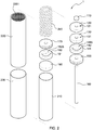
- FIG. 2 is an exploded view of a water-activated power generating device according to an embodiment of the present disclosure.
- the water-activated power generating device 1 further includes a silicon slice 130, a fixing ring 140, a first water storage element 150, an electrically conductive rod 160, electrolytic powder 240, a second water storage element 170, a second fixing ring 180, and a bottom conductive plate 190.
- the silicon slice 130 includes a cut 131 for air/gas to pass through.
- the silicon slice 130 is flexible and has a thickness, and thus the cut 131 is usually closed and can prevent liquid or water from passing through.
- the fixing ring 140 includes an inner space 140s and a notch 141.
- the inner space 140s can hold the air/gas produced during the chemical reactions of the water-activated power generating device 1.
- the air/gas accumulated in the inner space 140s will slowly leak out through the cut 131 and the air vent 121 when the pressure within the inner space 140s increases. Therefore, the inner space 140s works as a pressure controller and can prevent damage to the water-activated power generating device 1 due to over-pressure.
- the notch 141 is aligned with the air vent 121 and the cut 131.
- the notch 141 is aligned with the cut 131 of silicon slice and the air vent 121 of the top plate in a direction parallel to the inner surface 2201 of the electrode structure 220.
- Water can be put into the water-activated power generating device 1 through the air vent 121, the cut 131 and the notch 141, and then the water-activated power generating device 1 will start to generate power.
- the first water storage element 150 and the second water storage element 170 are made of a water-absorbing material.
- the first water storage element 150 and the second water storage element 170 are designed to hold water that is necessary for the water-activated power generating device 1 to generate power.
- the first water storage element 150 and the second water storage element 170 include wood pulp cotton.
- the first water storage element 150 and the second water storage element 170 include bibulous paper.
- the first water storage element 150 and the second water storage element 170 include at least one of hemp, bamboo, microfiber, and plastic fibers.
- the conductive rod 160 penetrates the top plate 120, the silicon slice 130, the fixing ring 140, and the first water storage element 150.
- the conductive rod 160 is electrically connected to the conductive cap 110.
- the conductive rod 160 is made of conductive materials such as metal, alloy or any other suitable materials.
- the conductive rod 160 includes at least one of petroleum coke, coal, graphite, or carbon black. The conductive rod 160 will not be consumed during the chemical reactions of the water-activated power generating device 1.
- the conductive rod 160 is used for conducting current and/or electrons/ions.
- the electrolytic powder 240 is disposed between the first water storage element 150 and the second water storage element 170 and between the conductive rod 160 and the isolation film 210.
- the isolation film 210 can avoid direct contact between the electrolytic powder 240 and the electrode structure 220.
- the isolation film 210 is porous. That is, the isolation film 210 includes spaces or holes through which liquid, air or electrons/ions may pass.
- the isolation film 210 can be made of any suitable material.
- the isolation film 210 includes polyethylene (PE).
- the isolation film 210 includes polypropylene (PP).
- the electrolytic powder 240 comprises particles of Carbon (C) and Nickel (Ni). In some embodiments, the electrolytic powder 240 comprises at least one of Polytetrafluoroethylene (PTFE), super-conductive carbon black, and graphite. In some embodiments, the diameter of the particle of the electrolytic powder 240 is in a range of 20 to 50 nanometers (nm). The small diameter of the particle of the electrolytic powder 240 causes the electrolytic powder 240 to have a greater surface area for chemical reactions. Therefore, the capacity of the water-activated power generating device 1 can be increased and the current magnitude of the water-activated power generating device 1 can also be increased.
- PTFE Polytetrafluoroethylene
- the second fixing ring 180 includes substantially the same shape of the fixing ring 140. However, in some embodiments, the notch 181 can be eliminated from the second fixing ring 180.
- the inner space 180s of the second fixing ring 180 is able to withhold the air/gas produced during the chemical reactions of the water-activated power generating device 1.
- the inner space 180s works as a pressure controller and can prevent damage to the water-activated power generating device 1 resulting from over-pressure.
- the electrode structure 220 includes a hollow cylindrical shape. In some embodiments, the electrode structure 220 includes a hollow rectangle shape.
- the electrode structure 220 includes Magnesium (Mg) and Aluminum (Al).
- the electrode structure 220 is an alloy comprising Magnesium (Mg) and Aluminum (Al).
- the electrode structure 220 is made of Magnesium alloy.
- the electrode structure 220 comprises Aluminum (Al) in a range of 2% to 6%.
- the electrode structure 220 comprises Aluminum (Al) in a range of 2% to 6% by weight.
- the electrode structure 220 comprises Aluminum (Al) in a range of 2% to 6% by volume.
- the inner surface 2201 of the electrode structure 220 is not flat.
- the inner surface 2201 of the electrode structure 220 includes micro patterns.
- the inner surface 2201 of the electrode structure 220 includes patterns formed by micro-etching. The micro patterns on the inner surface 2201 of the electrode structure 220 increase the reaction surface of the electrode structure 220. Therefore, the capacity of the water-activated power generating device 1 can be increased and the current magnitude of the water-activated power generating device 1 can also be increased.
- Mg Magnesium
- the Mg electrode in traditional water battery tends to expand/bulge during chemical reactions.
- the deformation of the Mg electrode in a traditional water battery will result in a short-circuiting problem that destroys the function and decreases the life of a traditional water battery.
- the micro patterns on the inner surface 2201 of the electrode structure 220 and the small diameter of the particle of the electrolytic powder 240 will have the advantage of gentle chemical reactions. Therefore, the expansion of the electrode structure 220 can be well controlled. In some embodiments, the expansion of the electrode structure 220 is reduced by up to 60% compared to the Mg electrode used in traditional water batteries.
- the bottom conductive plate 190 is made of conductive material such as metal, alloy or any other suitable materials.
- the bottom conductive plate is disposed at the bottom of the electrode structure 220 and electrically connected to the electrode structure 220.
- the current produced by the water-activated power generating device 1 can be provided to external electronic devices through the conductive cap 110 and the bottom conductive plate 190.
- FIG. 3 is a schematic view of a water-activated power generating device according to an embodiment of the subject invention.
- the wrapper 230 is disposed on the outer surface of the electrode structure 220 and covers a portion of the top plate 120 and a portion of the bottom conductive plate 190.
- the air vent 121 and the cut 131 forms a channel for air/gas produced during the chemical reactions of the water-activated power generating device 1. The air/gas produced during the chemical reactions will first accumulate within the space 140s and then gradually leak out through the cut 131 and the air vent 121.
- the electrolytic powder 240 is sandwiched by the first water storage element 150 and the second water storage element 170.
- Water can be injected into the water-activated power generating device 1 through the air vent 121, the cut 131 and the notch 141.
- the injected water will be held within the first water storage element 150 and the second water storage element 170.
- the injected water will also be held within the space between the particles of electrolytic powder 240.
- water contained between the first water storage element 150 and the second water storage element 170 serves as a medium for electron/ion transmission.
- FIG. 3A is an enlarged view of a portion of the water-activated power generating device 1 shown in circle A of FIG. 3 .
- the isolation film 210 is disposed adjacent to the inner surface 2201 of the electrode structure 220.
Landscapes
- Chemical & Material Sciences (AREA)
- Chemical Kinetics & Catalysis (AREA)
- Electrochemistry (AREA)
- General Chemical & Material Sciences (AREA)
- Engineering & Computer Science (AREA)
- Manufacturing & Machinery (AREA)
- Hybrid Cells (AREA)
- Electrolytic Production Of Non-Metals, Compounds, Apparatuses Therefor (AREA)
Applications Claiming Priority (1)
| Application Number | Priority Date | Filing Date | Title |
|---|---|---|---|
| US16/037,071 US10665869B2 (en) | 2018-07-17 | 2018-07-17 | Water-activated power generating device with vents |
Publications (2)
| Publication Number | Publication Date |
|---|---|
| EP3598547A1 true EP3598547A1 (de) | 2020-01-22 |
| EP3598547B1 EP3598547B1 (de) | 2021-06-02 |
Family
ID=67105954
Family Applications (1)
| Application Number | Title | Priority Date | Filing Date |
|---|---|---|---|
| EP19183029.8A Active EP3598547B1 (de) | 2018-07-17 | 2019-06-27 | Wasseraktivierte stromerzeugungsvorrichtung |
Country Status (4)
| Country | Link |
|---|---|
| US (1) | US10665869B2 (de) |
| EP (1) | EP3598547B1 (de) |
| CN (1) | CN110729496A (de) |
| TW (2) | TWI709276B (de) |
Families Citing this family (1)
| Publication number | Priority date | Publication date | Assignee | Title |
|---|---|---|---|---|
| US10920741B1 (en) | 2020-01-21 | 2021-02-16 | Bingyuan Duan | Submersible power generating system for generating electricity via total potential energy of still water |
Citations (2)
| Publication number | Priority date | Publication date | Assignee | Title |
|---|---|---|---|---|
| WO2010143636A1 (ja) * | 2009-06-09 | 2010-12-16 | 日本協能電子株式会社 | 水電池 |
| US20170092961A1 (en) * | 2015-09-30 | 2017-03-30 | Kuo Ming LIAW | Water-activated power bank structure |
Family Cites Families (5)
| Publication number | Priority date | Publication date | Assignee | Title |
|---|---|---|---|---|
| US20080248386A1 (en) * | 2007-04-05 | 2008-10-09 | Obrovac Mark N | Electrodes with raised patterns |
| US9905860B2 (en) * | 2013-06-28 | 2018-02-27 | Polyplus Battery Company | Water activated battery system having enhanced start-up behavior |
| CN203674306U (zh) * | 2013-12-07 | 2014-06-25 | 深圳市协能创新电子有限公司 | 加水电池 |
| TWI574454B (zh) * | 2015-02-02 | 2017-03-11 | 高松年 | 水致動發電裝置 |
| CN107482227A (zh) * | 2017-08-11 | 2017-12-15 | 深圳海能动力控股有限公司 | 电池正极纳米合成材料制备方法及镁基注水电池 |
-
2018
- 2018-07-17 US US16/037,071 patent/US10665869B2/en not_active Expired - Fee Related
-
2019
- 2019-06-27 EP EP19183029.8A patent/EP3598547B1/de active Active
- 2019-07-11 CN CN201910624599.9A patent/CN110729496A/zh active Pending
- 2019-07-12 TW TW108124606A patent/TWI709276B/zh active
- 2019-07-12 TW TW108209112U patent/TWM594278U/zh not_active IP Right Cessation
Patent Citations (2)
| Publication number | Priority date | Publication date | Assignee | Title |
|---|---|---|---|---|
| WO2010143636A1 (ja) * | 2009-06-09 | 2010-12-16 | 日本協能電子株式会社 | 水電池 |
| US20170092961A1 (en) * | 2015-09-30 | 2017-03-30 | Kuo Ming LIAW | Water-activated power bank structure |
Also Published As
| Publication number | Publication date |
|---|---|
| US10665869B2 (en) | 2020-05-26 |
| EP3598547B1 (de) | 2021-06-02 |
| TWM594278U (zh) | 2020-04-21 |
| US20200028185A1 (en) | 2020-01-23 |
| CN110729496A (zh) | 2020-01-24 |
| TW202011633A (zh) | 2020-03-16 |
| TWI709276B (zh) | 2020-11-01 |
Similar Documents
| Publication | Publication Date | Title |
|---|---|---|
| KR101111073B1 (ko) | 이차전지용 캡 어셈블리 | |
| US3143441A (en) | Diaphragm valve for venting fluid | |
| EP3598547B1 (de) | Wasseraktivierte stromerzeugungsvorrichtung | |
| US8338023B2 (en) | AA alkaline battery | |
| JP2005525678A (ja) | 向上した放電性能を有する円筒形のアルカリ電池 | |
| US3355329A (en) | Cell having integral valve, terminal, and contact member assembly | |
| JP4806936B2 (ja) | 密閉型電池 | |
| JPH10106618A (ja) | 密閉型アルカリ蓄電池 | |
| JP2010186667A (ja) | コイン形電池 | |
| HK40021418A (en) | Water-activated power generating device | |
| JP2020013670A (ja) | 水活性化電力生成デバイス | |
| US3485677A (en) | Dry cell battery | |
| KR20210044114A (ko) | 원통형 전지 및 원통형 전지 제조 방법 | |
| JP3987862B2 (ja) | 蓄電装置 | |
| US3773562A (en) | Alkaline primary battery cells | |
| KR102762527B1 (ko) | 울트라 커패시터 | |
| JP2005276698A (ja) | アルカリ電池 | |
| JP2007066762A (ja) | 電池缶およびそれを用いたアルカリ乾電池 | |
| CN209133640U (zh) | 一种耐深度放电碱性电池 | |
| CN110073521A (zh) | 硬币形电池 | |
| US3503811A (en) | Dry cell with novel venting means | |
| US3494801A (en) | Dry cell with novel venting means | |
| CN221150077U (zh) | 一种高温型防爆电池 | |
| KR100858797B1 (ko) | 캡조립체와, 이를 채용한 이차전지 | |
| KR101198029B1 (ko) | 공기 아연 전지 |
Legal Events
| Date | Code | Title | Description |
|---|---|---|---|
| PUAI | Public reference made under article 153(3) epc to a published international application that has entered the european phase |
Free format text: ORIGINAL CODE: 0009012 |
|
| STAA | Information on the status of an ep patent application or granted ep patent |
Free format text: STATUS: REQUEST FOR EXAMINATION WAS MADE |
|
| 17P | Request for examination filed |
Effective date: 20190627 |
|
| AK | Designated contracting states |
Kind code of ref document: A1 Designated state(s): AL AT BE BG CH CY CZ DE DK EE ES FI FR GB GR HR HU IE IS IT LI LT LU LV MC MK MT NL NO PL PT RO RS SE SI SK SM TR |
|
| AX | Request for extension of the european patent |
Extension state: BA ME |
|
| GRAP | Despatch of communication of intention to grant a patent |
Free format text: ORIGINAL CODE: EPIDOSNIGR1 |
|
| STAA | Information on the status of an ep patent application or granted ep patent |
Free format text: STATUS: GRANT OF PATENT IS INTENDED |
|
| RIC1 | Information provided on ipc code assigned before grant |
Ipc: H01M 4/46 20060101ALI20201124BHEP Ipc: H01M 6/34 20060101ALI20201124BHEP Ipc: H01M 6/04 20060101AFI20201124BHEP Ipc: H01M 6/32 20060101ALI20201124BHEP |
|
| INTG | Intention to grant announced |
Effective date: 20201218 |
|
| GRAS | Grant fee paid |
Free format text: ORIGINAL CODE: EPIDOSNIGR3 |
|
| GRAA | (expected) grant |
Free format text: ORIGINAL CODE: 0009210 |
|
| STAA | Information on the status of an ep patent application or granted ep patent |
Free format text: STATUS: THE PATENT HAS BEEN GRANTED |
|
| REG | Reference to a national code |
Ref country code: CH Ref legal event code: EP |
|
| AK | Designated contracting states |
Kind code of ref document: B1 Designated state(s): AL AT BE BG CH CY CZ DE DK EE ES FI FR GB GR HR HU IE IS IT LI LT LU LV MC MK MT NL NO PL PT RO RS SE SI SK SM TR |
|
| REG | Reference to a national code |
Ref country code: GB Ref legal event code: FG4D |
|
| REG | Reference to a national code |
Ref country code: AT Ref legal event code: REF Ref document number: 1399270 Country of ref document: AT Kind code of ref document: T Effective date: 20210615 |
|
| REG | Reference to a national code |
Ref country code: IE Ref legal event code: FG4D |
|
| REG | Reference to a national code |
Ref country code: DE Ref legal event code: R096 Ref document number: 602019005013 Country of ref document: DE |
|
| REG | Reference to a national code |
Ref country code: NL Ref legal event code: FP |
|
| PGFP | Annual fee paid to national office [announced via postgrant information from national office to epo] |
Ref country code: FR Payment date: 20210622 Year of fee payment: 3 |
|
| REG | Reference to a national code |
Ref country code: LT Ref legal event code: MG9D |
|
| PG25 | Lapsed in a contracting state [announced via postgrant information from national office to epo] |
Ref country code: FI Free format text: LAPSE BECAUSE OF FAILURE TO SUBMIT A TRANSLATION OF THE DESCRIPTION OR TO PAY THE FEE WITHIN THE PRESCRIBED TIME-LIMIT Effective date: 20210602 Ref country code: LT Free format text: LAPSE BECAUSE OF FAILURE TO SUBMIT A TRANSLATION OF THE DESCRIPTION OR TO PAY THE FEE WITHIN THE PRESCRIBED TIME-LIMIT Effective date: 20210602 Ref country code: HR Free format text: LAPSE BECAUSE OF FAILURE TO SUBMIT A TRANSLATION OF THE DESCRIPTION OR TO PAY THE FEE WITHIN THE PRESCRIBED TIME-LIMIT Effective date: 20210602 Ref country code: BG Free format text: LAPSE BECAUSE OF FAILURE TO SUBMIT A TRANSLATION OF THE DESCRIPTION OR TO PAY THE FEE WITHIN THE PRESCRIBED TIME-LIMIT Effective date: 20210902 |
|
| REG | Reference to a national code |
Ref country code: AT Ref legal event code: MK05 Ref document number: 1399270 Country of ref document: AT Kind code of ref document: T Effective date: 20210602 |
|
| PG25 | Lapsed in a contracting state [announced via postgrant information from national office to epo] |
Ref country code: GR Free format text: LAPSE BECAUSE OF FAILURE TO SUBMIT A TRANSLATION OF THE DESCRIPTION OR TO PAY THE FEE WITHIN THE PRESCRIBED TIME-LIMIT Effective date: 20210903 Ref country code: SE Free format text: LAPSE BECAUSE OF FAILURE TO SUBMIT A TRANSLATION OF THE DESCRIPTION OR TO PAY THE FEE WITHIN THE PRESCRIBED TIME-LIMIT Effective date: 20210602 Ref country code: RS Free format text: LAPSE BECAUSE OF FAILURE TO SUBMIT A TRANSLATION OF THE DESCRIPTION OR TO PAY THE FEE WITHIN THE PRESCRIBED TIME-LIMIT Effective date: 20210602 Ref country code: NO Free format text: LAPSE BECAUSE OF FAILURE TO SUBMIT A TRANSLATION OF THE DESCRIPTION OR TO PAY THE FEE WITHIN THE PRESCRIBED TIME-LIMIT Effective date: 20210902 Ref country code: PL Free format text: LAPSE BECAUSE OF FAILURE TO SUBMIT A TRANSLATION OF THE DESCRIPTION OR TO PAY THE FEE WITHIN THE PRESCRIBED TIME-LIMIT Effective date: 20210602 Ref country code: LV Free format text: LAPSE BECAUSE OF FAILURE TO SUBMIT A TRANSLATION OF THE DESCRIPTION OR TO PAY THE FEE WITHIN THE PRESCRIBED TIME-LIMIT Effective date: 20210602 |
|
| PGFP | Annual fee paid to national office [announced via postgrant information from national office to epo] |
Ref country code: DE Payment date: 20210629 Year of fee payment: 3 |
|
| PG25 | Lapsed in a contracting state [announced via postgrant information from national office to epo] |
Ref country code: SK Free format text: LAPSE BECAUSE OF FAILURE TO SUBMIT A TRANSLATION OF THE DESCRIPTION OR TO PAY THE FEE WITHIN THE PRESCRIBED TIME-LIMIT Effective date: 20210602 Ref country code: EE Free format text: LAPSE BECAUSE OF FAILURE TO SUBMIT A TRANSLATION OF THE DESCRIPTION OR TO PAY THE FEE WITHIN THE PRESCRIBED TIME-LIMIT Effective date: 20210602 Ref country code: ES Free format text: LAPSE BECAUSE OF FAILURE TO SUBMIT A TRANSLATION OF THE DESCRIPTION OR TO PAY THE FEE WITHIN THE PRESCRIBED TIME-LIMIT Effective date: 20210602 Ref country code: CZ Free format text: LAPSE BECAUSE OF FAILURE TO SUBMIT A TRANSLATION OF THE DESCRIPTION OR TO PAY THE FEE WITHIN THE PRESCRIBED TIME-LIMIT Effective date: 20210602 Ref country code: AT Free format text: LAPSE BECAUSE OF FAILURE TO SUBMIT A TRANSLATION OF THE DESCRIPTION OR TO PAY THE FEE WITHIN THE PRESCRIBED TIME-LIMIT Effective date: 20210602 Ref country code: RO Free format text: LAPSE BECAUSE OF FAILURE TO SUBMIT A TRANSLATION OF THE DESCRIPTION OR TO PAY THE FEE WITHIN THE PRESCRIBED TIME-LIMIT Effective date: 20210602 Ref country code: PT Free format text: LAPSE BECAUSE OF FAILURE TO SUBMIT A TRANSLATION OF THE DESCRIPTION OR TO PAY THE FEE WITHIN THE PRESCRIBED TIME-LIMIT Effective date: 20211004 Ref country code: SM Free format text: LAPSE BECAUSE OF FAILURE TO SUBMIT A TRANSLATION OF THE DESCRIPTION OR TO PAY THE FEE WITHIN THE PRESCRIBED TIME-LIMIT Effective date: 20210602 |
|
| REG | Reference to a national code |
Ref country code: DE Ref legal event code: R097 Ref document number: 602019005013 Country of ref document: DE |
|
| REG | Reference to a national code |
Ref country code: BE Ref legal event code: MM Effective date: 20210630 |
|
| PG25 | Lapsed in a contracting state [announced via postgrant information from national office to epo] |
Ref country code: MC Free format text: LAPSE BECAUSE OF FAILURE TO SUBMIT A TRANSLATION OF THE DESCRIPTION OR TO PAY THE FEE WITHIN THE PRESCRIBED TIME-LIMIT Effective date: 20210602 Ref country code: LU Free format text: LAPSE BECAUSE OF NON-PAYMENT OF DUE FEES Effective date: 20210627 |
|
| PLBE | No opposition filed within time limit |
Free format text: ORIGINAL CODE: 0009261 |
|
| STAA | Information on the status of an ep patent application or granted ep patent |
Free format text: STATUS: NO OPPOSITION FILED WITHIN TIME LIMIT |
|
| PG25 | Lapsed in a contracting state [announced via postgrant information from national office to epo] |
Ref country code: IE Free format text: LAPSE BECAUSE OF NON-PAYMENT OF DUE FEES Effective date: 20210627 Ref country code: DK Free format text: LAPSE BECAUSE OF FAILURE TO SUBMIT A TRANSLATION OF THE DESCRIPTION OR TO PAY THE FEE WITHIN THE PRESCRIBED TIME-LIMIT Effective date: 20210602 |
|
| 26N | No opposition filed |
Effective date: 20220303 |
|
| PG25 | Lapsed in a contracting state [announced via postgrant information from national office to epo] |
Ref country code: AL Free format text: LAPSE BECAUSE OF FAILURE TO SUBMIT A TRANSLATION OF THE DESCRIPTION OR TO PAY THE FEE WITHIN THE PRESCRIBED TIME-LIMIT Effective date: 20210602 |
|
| PG25 | Lapsed in a contracting state [announced via postgrant information from national office to epo] |
Ref country code: IT Free format text: LAPSE BECAUSE OF FAILURE TO SUBMIT A TRANSLATION OF THE DESCRIPTION OR TO PAY THE FEE WITHIN THE PRESCRIBED TIME-LIMIT Effective date: 20210602 Ref country code: BE Free format text: LAPSE BECAUSE OF NON-PAYMENT OF DUE FEES Effective date: 20210630 |
|
| REG | Reference to a national code |
Ref country code: DE Ref legal event code: R119 Ref document number: 602019005013 Country of ref document: DE |
|
| REG | Reference to a national code |
Ref country code: CH Ref legal event code: PL |
|
| REG | Reference to a national code |
Ref country code: NL Ref legal event code: MM Effective date: 20220701 |
|
| PG25 | Lapsed in a contracting state [announced via postgrant information from national office to epo] |
Ref country code: NL Free format text: LAPSE BECAUSE OF NON-PAYMENT OF DUE FEES Effective date: 20220701 |
|
| PG25 | Lapsed in a contracting state [announced via postgrant information from national office to epo] |
Ref country code: LI Free format text: LAPSE BECAUSE OF NON-PAYMENT OF DUE FEES Effective date: 20220630 Ref country code: FR Free format text: LAPSE BECAUSE OF NON-PAYMENT OF DUE FEES Effective date: 20220630 Ref country code: CH Free format text: LAPSE BECAUSE OF NON-PAYMENT OF DUE FEES Effective date: 20220630 |
|
| PG25 | Lapsed in a contracting state [announced via postgrant information from national office to epo] |
Ref country code: DE Free format text: LAPSE BECAUSE OF NON-PAYMENT OF DUE FEES Effective date: 20230103 |
|
| PG25 | Lapsed in a contracting state [announced via postgrant information from national office to epo] |
Ref country code: CY Free format text: LAPSE BECAUSE OF FAILURE TO SUBMIT A TRANSLATION OF THE DESCRIPTION OR TO PAY THE FEE WITHIN THE PRESCRIBED TIME-LIMIT Effective date: 20210602 |
|
| PG25 | Lapsed in a contracting state [announced via postgrant information from national office to epo] |
Ref country code: HU Free format text: LAPSE BECAUSE OF FAILURE TO SUBMIT A TRANSLATION OF THE DESCRIPTION OR TO PAY THE FEE WITHIN THE PRESCRIBED TIME-LIMIT; INVALID AB INITIO Effective date: 20190627 |
|
| GBPC | Gb: european patent ceased through non-payment of renewal fee |
Effective date: 20230627 |
|
| PG25 | Lapsed in a contracting state [announced via postgrant information from national office to epo] |
Ref country code: MK Free format text: LAPSE BECAUSE OF FAILURE TO SUBMIT A TRANSLATION OF THE DESCRIPTION OR TO PAY THE FEE WITHIN THE PRESCRIBED TIME-LIMIT Effective date: 20210602 Ref country code: GB Free format text: LAPSE BECAUSE OF NON-PAYMENT OF DUE FEES Effective date: 20230627 |
|
| PG25 | Lapsed in a contracting state [announced via postgrant information from national office to epo] |
Ref country code: TR Free format text: LAPSE BECAUSE OF FAILURE TO SUBMIT A TRANSLATION OF THE DESCRIPTION OR TO PAY THE FEE WITHIN THE PRESCRIBED TIME-LIMIT Effective date: 20210602 |
|
| PG25 | Lapsed in a contracting state [announced via postgrant information from national office to epo] |
Ref country code: MT Free format text: LAPSE BECAUSE OF FAILURE TO SUBMIT A TRANSLATION OF THE DESCRIPTION OR TO PAY THE FEE WITHIN THE PRESCRIBED TIME-LIMIT Effective date: 20210602 |