EP3598546A1 - Negativelektrode für lithium-metall-batterie und lithium-metall-batterie, dieselbe umfassend - Google Patents
Negativelektrode für lithium-metall-batterie und lithium-metall-batterie, dieselbe umfassend Download PDFInfo
- Publication number
- EP3598546A1 EP3598546A1 EP18891822.1A EP18891822A EP3598546A1 EP 3598546 A1 EP3598546 A1 EP 3598546A1 EP 18891822 A EP18891822 A EP 18891822A EP 3598546 A1 EP3598546 A1 EP 3598546A1
- Authority
- EP
- European Patent Office
- Prior art keywords
- pores
- lithium metal
- anode
- current collector
- lithium
- Prior art date
- Legal status (The legal status is an assumption and is not a legal conclusion. Google has not performed a legal analysis and makes no representation as to the accuracy of the status listed.)
- Pending
Links
Images


Classifications
-
- H—ELECTRICITY
- H01—ELECTRIC ELEMENTS
- H01M—PROCESSES OR MEANS, e.g. BATTERIES, FOR THE DIRECT CONVERSION OF CHEMICAL ENERGY INTO ELECTRICAL ENERGY
- H01M4/00—Electrodes
- H01M4/02—Electrodes composed of, or comprising, active material
- H01M4/64—Carriers or collectors
- H01M4/70—Carriers or collectors characterised by shape or form
-
- H—ELECTRICITY
- H01—ELECTRIC ELEMENTS
- H01M—PROCESSES OR MEANS, e.g. BATTERIES, FOR THE DIRECT CONVERSION OF CHEMICAL ENERGY INTO ELECTRICAL ENERGY
- H01M4/00—Electrodes
- H01M4/02—Electrodes composed of, or comprising, active material
- H01M4/64—Carriers or collectors
- H01M4/70—Carriers or collectors characterised by shape or form
- H01M4/72—Grids
- H01M4/74—Meshes or woven material; Expanded metal
- H01M4/742—Meshes or woven material; Expanded metal perforated material
-
- H—ELECTRICITY
- H01—ELECTRIC ELEMENTS
- H01M—PROCESSES OR MEANS, e.g. BATTERIES, FOR THE DIRECT CONVERSION OF CHEMICAL ENERGY INTO ELECTRICAL ENERGY
- H01M10/00—Secondary cells; Manufacture thereof
- H01M10/05—Accumulators with non-aqueous electrolyte
- H01M10/052—Li-accumulators
-
- H—ELECTRICITY
- H01—ELECTRIC ELEMENTS
- H01M—PROCESSES OR MEANS, e.g. BATTERIES, FOR THE DIRECT CONVERSION OF CHEMICAL ENERGY INTO ELECTRICAL ENERGY
- H01M10/00—Secondary cells; Manufacture thereof
- H01M10/05—Accumulators with non-aqueous electrolyte
- H01M10/052—Li-accumulators
- H01M10/0525—Rocking-chair batteries, i.e. batteries with lithium insertion or intercalation in both electrodes; Lithium-ion batteries
-
- H—ELECTRICITY
- H01—ELECTRIC ELEMENTS
- H01M—PROCESSES OR MEANS, e.g. BATTERIES, FOR THE DIRECT CONVERSION OF CHEMICAL ENERGY INTO ELECTRICAL ENERGY
- H01M4/00—Electrodes
- H01M4/02—Electrodes composed of, or comprising, active material
- H01M4/13—Electrodes for accumulators with non-aqueous electrolyte, e.g. for lithium-accumulators; Processes of manufacture thereof
- H01M4/134—Electrodes based on metals, Si or alloys
-
- H—ELECTRICITY
- H01—ELECTRIC ELEMENTS
- H01M—PROCESSES OR MEANS, e.g. BATTERIES, FOR THE DIRECT CONVERSION OF CHEMICAL ENERGY INTO ELECTRICAL ENERGY
- H01M4/00—Electrodes
- H01M4/02—Electrodes composed of, or comprising, active material
- H01M4/36—Selection of substances as active materials, active masses, active liquids
- H01M4/38—Selection of substances as active materials, active masses, active liquids of elements or alloys
- H01M4/381—Alkaline or alkaline earth metals elements
- H01M4/382—Lithium
-
- H—ELECTRICITY
- H01—ELECTRIC ELEMENTS
- H01M—PROCESSES OR MEANS, e.g. BATTERIES, FOR THE DIRECT CONVERSION OF CHEMICAL ENERGY INTO ELECTRICAL ENERGY
- H01M4/00—Electrodes
- H01M4/02—Electrodes composed of, or comprising, active material
- H01M4/64—Carriers or collectors
- H01M4/66—Selection of materials
- H01M4/661—Metal or alloys, e.g. alloy coatings
-
- H—ELECTRICITY
- H01—ELECTRIC ELEMENTS
- H01M—PROCESSES OR MEANS, e.g. BATTERIES, FOR THE DIRECT CONVERSION OF CHEMICAL ENERGY INTO ELECTRICAL ENERGY
- H01M4/00—Electrodes
- H01M4/02—Electrodes composed of, or comprising, active material
- H01M4/64—Carriers or collectors
- H01M4/66—Selection of materials
- H01M4/661—Metal or alloys, e.g. alloy coatings
- H01M4/662—Alloys
-
- H—ELECTRICITY
- H01—ELECTRIC ELEMENTS
- H01M—PROCESSES OR MEANS, e.g. BATTERIES, FOR THE DIRECT CONVERSION OF CHEMICAL ENERGY INTO ELECTRICAL ENERGY
- H01M4/00—Electrodes
- H01M4/02—Electrodes composed of, or comprising, active material
- H01M2004/026—Electrodes composed of, or comprising, active material characterised by the polarity
- H01M2004/027—Negative electrodes
-
- H—ELECTRICITY
- H01—ELECTRIC ELEMENTS
- H01M—PROCESSES OR MEANS, e.g. BATTERIES, FOR THE DIRECT CONVERSION OF CHEMICAL ENERGY INTO ELECTRICAL ENERGY
- H01M4/00—Electrodes
- H01M4/02—Electrodes composed of, or comprising, active material
- H01M4/04—Processes of manufacture in general
- H01M4/0402—Methods of deposition of the material
- H01M4/0404—Methods of deposition of the material by coating on electrode collectors
-
- H—ELECTRICITY
- H01—ELECTRIC ELEMENTS
- H01M—PROCESSES OR MEANS, e.g. BATTERIES, FOR THE DIRECT CONVERSION OF CHEMICAL ENERGY INTO ELECTRICAL ENERGY
- H01M4/00—Electrodes
- H01M4/02—Electrodes composed of, or comprising, active material
- H01M4/04—Processes of manufacture in general
- H01M4/043—Processes of manufacture in general involving compressing or compaction
- H01M4/0435—Rolling or calendering
-
- H—ELECTRICITY
- H01—ELECTRIC ELEMENTS
- H01M—PROCESSES OR MEANS, e.g. BATTERIES, FOR THE DIRECT CONVERSION OF CHEMICAL ENERGY INTO ELECTRICAL ENERGY
- H01M4/00—Electrodes
- H01M4/02—Electrodes composed of, or comprising, active material
- H01M4/13—Electrodes for accumulators with non-aqueous electrolyte, e.g. for lithium-accumulators; Processes of manufacture thereof
- H01M4/139—Processes of manufacture
- H01M4/1395—Processes of manufacture of electrodes based on metals, Si or alloys
-
- Y—GENERAL TAGGING OF NEW TECHNOLOGICAL DEVELOPMENTS; GENERAL TAGGING OF CROSS-SECTIONAL TECHNOLOGIES SPANNING OVER SEVERAL SECTIONS OF THE IPC; TECHNICAL SUBJECTS COVERED BY FORMER USPC CROSS-REFERENCE ART COLLECTIONS [XRACs] AND DIGESTS
- Y02—TECHNOLOGIES OR APPLICATIONS FOR MITIGATION OR ADAPTATION AGAINST CLIMATE CHANGE
- Y02E—REDUCTION OF GREENHOUSE GAS [GHG] EMISSIONS, RELATED TO ENERGY GENERATION, TRANSMISSION OR DISTRIBUTION
- Y02E60/00—Enabling technologies; Technologies with a potential or indirect contribution to GHG emissions mitigation
- Y02E60/10—Energy storage using batteries
Definitions
- the present invention relates to an anode for a lithium metal battery and a lithium metal battery including the same.
- a lithium metal battery uses lithium metal as anode active material, and uses electrochemical reactions in which, during the discharge of a battery, lithium metals of an anode lose electrons and move to a cathode through an electrolyte, and during the charge of a battery, lithium ions move to an anode through an electrolyte and are stored in an anode active material. It has an advantage in that it theoretically has very high energy capacity, compared to commercial lithium ion batteries using graphite, etc. as anode active material.
- the lithium metal battery despite the above advantage, has a difficulty in securing the reversibility of an anode, due to the structural limitations of anode current collectors suggested up to now, and thus has not been commercialized.
- a porous current collector including foam-shaped pores has been suggested.
- Such a porous current collector may be favorable for the initial charge because the pores can provide various directions and sufficient spaces where lithium ions are electrodeposited. Nevertheless, due to the random foam-shape of the pores, local blocking of the pores may occur during the repeated charge/discharge of a battery, and the reversibility of an anode may be gradually inhibited.
- the present invention presents an anode current collector that can inhibit local blocking during repeated charge/discharge processes of a battery, while providing various directions and sufficient space where lithium ions can enter during the charge of a lithium metal battery, and provides an optimal anode and battery designing method using the anode current collector.
- one embodiment of the present invention provides an anode for a lithium metal battery, wherein
- Another embodiment of the present invention provides a lithium metal battery designed such that a separator faces the second pores (pores having relatively larger diameters) of the anode current collector, using the anode for a lithium metal battery of one embodiment.
- the reversibility of a lithium metal battery can be secured, and the cycle life characteristic of a lithium metal battery can be improved.
- the term "combination(s) thereof included in the expression of a Markush type means mixtures or combinations of one or more selected from the group consisting of the constructional elements described in the expression of the Markush type, and means to include one or more selected from the group consisting of the constructional elements.
- One embodiment of the present invention provides an anode for a lithium metal battery, wherein
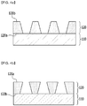
- the lithium metal anode of one embodiment has a structure wherein the first pores (pores having relatively small diameters) of an anode current collector face a lithium metal layer (110), and the second pores (pores having relatively large diameters) are exposed.
- the second pores (pores having relatively larger diameters) of an anode current collector face a separator.
- the second pores facing a separator becomes a wide entrance where lithium ions (specifically, lithium ions derived from an electrolyte impregnated in a separator) can easily enter.
- the lithium ions entering the wide entrance pass through the inside of the anode current collector and move to a lithium metal layer.
- various directions and sufficient space where lithium ions penetrating inside the anode current collector can enter are provided from the wide entrance facing a separator (second pores) to the narrow entrance facing a lithium metal layer (first pores), local blocking can be inhibited during repeated charge/discharge processes of a lithium metal battery.
- the lithium metal anode of one embodiment is used to design a lithium metal battery, the reversibility of a lithium metal anode can be secured, and the cycle life characteristic of a lithium metal battery can be improved.
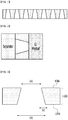
- FIG. 1 is a side view schematically showing the anode current collector.
- FIG. 2 schematically shows a part of the lithium metal battery applying the anode current collector of one embodiment.
- a lithium metal layer may be deposited on a side where the first pores having relatively small diameters are positioned, and a separator may be deposited on a side where the second pores having relatively large diameters are positioned.
- a cathode may be deposited on the other side of the separator, and an electrolyte may be impregnated in the separator to form a lithium metal battery.
- lithium ions of the electrolyte may move from the separator, penetrate the multiple holes, and be electrodeposited on the lithium metal layer.
- lithium ions may be deintercalated from the lithium metal layer, penetrate the multiple holes, and move to the separator.
- the second pores adjacent to the separator may provide a wide entrance where lithium ions of the electrolyte can easily enter. Further, the holes with gradually decreasing diameters from the second pores to the first pores may become a passage through which lithium ions of the electrolyte move.
- the wide entrance provided by the second pores adjacent to the separator, and the holes with gradually decreasing diameters from the second pores to the first pores may provide various directions and sufficient space where lithium ions can enter, and provide a favorable structure for inhibiting local blocking during the repeated charge/discharge processes of a battery.
- the anode current collector of one embodiment is used to form a lithium metal battery as shown in FIG. 2 , particularly, the reversibility of an anode can be secured, and the cycle life characteristic of a battery can be improved.
- the multiple holes may, independently from each other, have a constant diameter slope, which may gradually decrease, in a direction from the second pores to the first pores.
- lithium ions may enter the wide entrance (second pores) as explained above, pass through the holes, and move to a lithium metal layer.
- the slope of the diameter of the hole may be 30° to 60°, for example 40 to 50°, and within these ranges, various directions and sufficient space where lithium ions can enter can be provided, and it is favorable for inhibiting local blocking during repeated charge/discharge processes of a battery.
- the advantages can be achieved as long as the multiple holes, independently from each other, 1) have a pore structure opened to both sides of the metal plate, and 2) have a structure wherein the diameters of the pores decrease from one side to the other side of the metal plate.
- the diameter of the holes with a constant slope which may gradually increase, and the slope of the diameter of the holes within a specific range, are no more than examples, and the present invention is not limited thereby.
- the multiple holes may have a diameter of the first pores of 1 ⁇ m to 100 ⁇ m, for example, 50 ⁇ m to 70 ⁇ m.
- the pore diameter of the side where the lithium metal is deposited is 1 ⁇ m to 100 ⁇ m, for example 50 ⁇ m to 70 ⁇ m, in the anode current collector of one embodiment.
- the multiple holes may have a diameter of the second pores of 7 ⁇ m to 700 ⁇ m, for example, 200 ⁇ m to 350 ⁇ m.
- the pore diameter of the side where a separator is deposited is 7 ⁇ m to 700 ⁇ m, for example 200 ⁇ m to 350 ⁇ m, in the anode current collector of one embodiment.
- the thickness of the substrate on which the multiple holes are formed i.e., the metal plate, may be 5 ⁇ m to 300 ⁇ m, for example 100 ⁇ m to 150 ⁇ m.
- a diameter may increase by 0.1 ⁇ m to 3 ⁇ m per 1 ⁇ m thickness of the metal plate from the diameter of the first pores to the diameter of the second pores.
- the above advantages can be achieved as long as the multiple holes, independently from each other, 1) have a pore structure that is opened to both sides of the metal plate, and 2) have a structure wherein the diameters of the pores increase from one side to the other side of the metal plate.
- the diameter of the first pores, the diameter of the second pores, the thickness of the metal plate, and the degree of change in the hole diameter inside the metal plate, respectively within a specific range are no more than examples, and the present invention is not limited thereby.
- the multiple holes may be formed using soft molding, self-assembly of spherical particles, or photolithography. More specifically, as described below in the examples, photolithography may be used.
- the multiple holes may be formed on a metal plate using a conical, elliptic conical, or polypyramidal soft mold.
- the soft mold may consist of an elastic polymer, for example, PDMS (polydimethylsiloxane).
- PDMS polydimethylsiloxane
- etching may be progressed using photolithography on a metal or non-metal substrate, and the aimed shape may be transcribed to the elastic polymer.
- the substrate may be a Si wafer, but is not limited thereto, because all substrates to which photolithography can be applied may be used.
- a method of applying a soft mold includes three methods.
- a method of imparting conductivity to a soft mold itself and using the same, and a method of eliminating only a metal layer using a soft mold as a stamper for patterning, may be mentioned.
- a method of imparting conductivity may include plating Cu ions on the front side of a soft mold by electroless plating, and metal may be sputtered on a soft mold and then the cutting edges may be removed to form pores. If eliminating a metal part on which the pores are formed, the aimed metal plate may be obtained.
- the diameter of the holes, the diameter of the first pores, and/or the diameter of the second pores may be achieved, respectively within the above-explained range.
- a shape similar to a soft mold can also be obtained using spherical particles having a Gaussian distribution according to the diameter of the particles.
- the size of the spherical particles may be 1 ⁇ m to 30 ⁇ m, and it may be realized by a self-assembly mechanism by liquid-phase precipitation. If spherical particles are dripped on a substrate which is completely dipped in liquid, they are stacked according to particle size by gravity, and a shape wherein a conical, elliptic conical, or polypyramidal shape similar to the soft mold is distributed on the surface may be realized.
- the diameter of the holes, the diameter of the first pores, and/or the diameter of the second pores may be achieved, respectively within the above-explained range.
- the irradiated light may be UV, which may generally have a wavelength band of 10 nm to 500 nm. More specifically, the central wavelength may be positioned in the range of 300 nm to 500 nm.
- a photoresist and a photomask are positioned and light is irradiated so that aimed holes may be formed on a metal plate, and a part of metal excluding the photoresist and photomask is etched.
- the sizes of the photoresist and photomask may be sequentially controlled to form the multiple holes having a gradient. In this case, the diameter of the holes, the diameter of the first pores, and/or the diameter of the second pores, respectively within the above-explained range, may be achieved.
- the multiple holes may, independently from each other, have a shape of a circular truncated cone, an elliptic truncated cone, or a truncated polypyramid by controlling the forming method and conditions.
- the multiple holes may be formed respectively in the shape of a circular truncated cone.
- the narrower upper side may form the first pore
- the wider lower side may form the second pore
- the slope may correspond to the slope of the diameter of the hole.
- the above illustrated shapes are no more than examples, and the present invention is not limited thereto.
- the volume occupied by the multiple holes in the total volume (100 vol%) including the metal plate and the multiple holes may be 50 to 90 vol%.
- various directions and sufficient spaces where lithium ions can enter may be provided, and it is favorable for inhibiting local blocking during the repeated charge/discharge processes of a battery.
- this is no more than an example, and the present invention is not limited thereto.
- the metal plate may consist of copper(Cu), or an alloy of copper (Cu) and other metals.
- the metal plate is not specifically limited as long as it consists of Cu or a Cu-alloy material having high conductivity, without inducing chemical changes in a battery.
- the metal plate may be a film, a sheet, a foil, etc. having a thickness of 3 to 500 ⁇ m, for example, 100 to 150 ⁇ m, as explained above, and the above-explained multiple holes may be formed on such a metal plate. Further, the metal plate may have fine unevenness formed on the surface so as to increase adhesion of a lithium metal layer and/or a separator.
- a method of depositing the lithium metal layer on the current collector of one embodiment a method commonly known in the art may be appropriately selected.
- the lithium metal layer may be deposited in a battery.
- the lithium metal layer may be deposited on the anode current collector.
- a lithium metal battery A lithium metal battery
- Another embodiment of the present invention provides a lithium metal battery including: the anode of one embodiment; a separator facing the second pores of the anode current collector; an electrolyte impregnated in the separator membrane; and a cathode facing the other side of the separator membrane.
- the lithium metal battery may be formed by depositing a lithium metal layer on a side where the first pores having relatively small diameters are positioned, depositing a separator on a side where the second pores having relatively large diameters are positioned, depositing a cathode on the other side of the separator, and impregnating an electrolyte in the separator.
- the construction is as described above in detail with reference to FIGS. 1 and 2 .
- the lithium metal battery of one embodiment includes the above-explained anode current collector, storage and deintercalation of lithium can be stably achieved in an anode including the above-explained anode current collector during the repeated charge/discharge processes of a battery, thus improving the cycle life characteristic.
- the lithium metal battery may use an electrolyte including a non-aqueous organic solvent and a lithium salt.
- the non-aqueous organic solvent functions as a medium through which ions involved in the electrochemical reactions of a battery can move.
- a carbonate-based, ester-base, ether-based, ketone-based, alcohol-based, or an aprotic solvent may be used.
- the carbonate-based solvent dimethyl carbonate (DMC), diethyl carbonate (DEC), dipropyl carbonate (DPC), methylpropyl carbonate (MPC), ethylpropyl carbonate (EPC), methylethyl carbonate (MEC), ethylene carbonate (EC), propylene carbonate (PC), butylene carbonate (BC), etc.
- ester-based solvent methyl acetate, ethyl acetate, n-propyl acetate, 1,1-dimethylethyl acetate, methyl propionate, ethylpropionate, ⁇ -butyrolactone, decanolide, valerolactone, mevalonolactone, caprolactone, etc.
- ether-based solvent dibutyl ether, tetraglyme, diglyme, dimethoxyethane, 2-methyltetrahydrofuran, tetrahydrofuran, etc.
- ketone-based solvent cyclohexanone etc.
- the alcohol-based solvent ethyl alcohol, isopropyl alcohol, etc.
- aprotic solvent nitriles such as R-CN (where R is a linear, branched, or cyclic C2-20 hydrocarbon group, and may include a double bond, an aromatic ring, or an ether bond), amides such as dimethylformamide, dioxolanes such as 1,3-dioxolane, sulfolanes, etc.
- R-CN where R is a linear, branched, or cyclic C2-20 hydrocarbon group, and may include a double bond, an aromatic ring, or an ether bond
- amides such as dimethylformamide, dioxolanes such as 1,3-dioxolane, sulfolanes, etc.
- the non-aqueous organic solvent may be used alone or in combinations of two or more kinds, and if used in combinations, the mixing ratio may be appropriately controlled according to the aimed performance of a battery, which may be easily understood by an ordinary skilled person in the art.
- the carbonate-based solvent it is preferable that a cyclic carbonate and a chain carbonate are used in combination.
- the cyclic carbonate and the chain carbonate may be mixed at a volume ratio of about 1:1 to about 1:9 so as to exhibit excellent performance of an electrolyte.
- the non-aqueous organic solvent may further include the aromatic hydrocarbon-based organic solvent in addition to the carbonate-based solvent.
- the carbonate-based solvent and the aromatic hydrocarbon-based organic solvent may be mixed at a volume ratio of about 1:1 to about 30:1.
- aromatic hydrocarbon-based organic solvent an aromatic hydrocarbon-based compound of the following Chemical Formula 1 may be used.
- R 1 to R 6 are, independently from each other, hydrogen, a halogen, a C1-10 alkyl group, a C1-10 haloalkyl group, or a combination thereof.
- benzene fluorobenzene, 1,2-difluorobenzene, 1,3-difluorobenzene, 1,4-difluorobenzene, 1,2,3-trifluorobenzene, 1,2,4-trifluorobenzene, chlorobenzene, 1,2-dichlorobenzene, 1,3-dichlorobenzene, 1,4-dichlorobenzen, 1,2,3-trichlorobenzen, 1,2,4-trichlorobenzene, iodobenzene, 1,2-diiodobenzen, 1,3-diiodobenzene, 1,4-diiodobenzene, 1,2,3-triiodobenzen, 1,2,4- triiodobenzene, toluene, fluorotoluene, 1,2-difluorotoluene, 1,3-difluorotoluene, 1,2,4-trifluorobenzene
- the non-aqueous electrolyte may further include a vinylene carbonate-based or an ethylene carbonate-based compound of the following Chemical Formula 2 so as to improve the cycle life of a battery.
- R 7 and R 8 are, independently from each other, hydrogen, a halogen group, a cyano group (CN), a nitro group (NO 2 ) or a C1-5 fluoroalkyl group, and at least one of the R 7 and R 8 is a halogen group, a cyano group (CN), a nitro group (NO 2 ), or a C1-5 fluoroalkyl group.
- ethylene carbonate-based compound difluoroethylene carbonate, chloroethylene carbonate, dichloroethylene carbonate, bromoethylene carbonate, dibromoethylene carbonate, nitroethylene carbonate, cyanoethylene carbonate, fluoroethylene carbonate, etc. may be mentioned.
- the amount used may be appropriately controlled to improve the cycle life.
- the lithium salt is a material that is dissolved in the non-aqueous organic solvent, and acts as a source of lithium ions in a battery, thus enabling the basic operation of a lithium secondary battery and facilitating the movement of lithium ions between a cathode and an anode.
- the lithium salt LiPF 6 , LiBF 4 , LiSbF 6 , LiAsF 6 , LiC 4 F 9 SO 3 , LiClO 4 , LiAlO 2 , LiAlCl 4 , LiN(C x F 2x+1 SO 2 )(C y F 2y+1 SO 2 ) (wherein x and y are natural numbers), Li
- the concentration of the lithium salt is preferably in the range of 0.1 to 2.0 M. If the concentration of the lithium salt is within the above range, an electrolyte may have appropriate conductivity and viscosity, and thus excellent electrolyte performance may be exhibited, and lithium ions may effectively move.
- the separator separates the cathode and the anode and provides a passage for lithium ions
- those commonly used in a lithium battery may be used without specific limitations. That is, those having low resistance to the movement of ions of an electrolyte and having an excellent electrolyte wetting property may be used.
- it may be selected from glass fiber, polyester, Teflon, polyethylene, polypropylene, polytetrafluoroethylene (PTFE), or combinations thereof, and it may be in the form of a non-woven fabric or woven fabric.
- PTFE polytetrafluoroethylene
- a polyolefin-based polymer separator such as polyethylene, polypropylene, etc.
- a coated separator including a ceramic component or a polymer material may be used so as to secure heat resistance or mechanical strength, and it may be optionally used in a monolayer or a multilayer structure.
- the cathode may include a cathode current collector, and a cathode mixture layer positioned on the cathode current collector.
- the cathode is prepared by mixing an active material and a binder, and if necessary, a conductive material, a filler, etc. in a solvent to prepare an electrode mixture in the form of a slurry, and coating the electrode mixture on an electrode current collector.
- a method of preparing an electrode is well known in the art, and thus detailed explanations thereof will be omitted herein.
- the cathode current collector may be generally formed with a thickness of 3 ⁇ 500 ⁇ m.
- a cathode current collector is not specifically limited as long as it has high conductivity without inducing chemical changes in a battery.
- stainless steel, aluminum, nickel, titanium, baked carbon, or aluminum, or stainless steel of which surface is treated with carbon, nickel, titanium, silver, etc. may be used.
- the collector may have fine unevenness on the surface to increase adhesion of the cathode active material, and it may be in various forms such as a film, a sheet, a foil, a net, a porous body, a foamed body, a non-woven fabric body, etc.
- the conductive material is not specifically limited as long as it has conductivity without inducing chemical changes in a battery, and for example, graphite such as natural graphite or artificial graphite; carbon black such as carbon black, acetylene black, Ketjen black, channel black, furnace black, lamp black, summer black, etc.; a conductive fiber such as carbon fiber or metal fiber, etc.; a metal powder such as fluorinated carbon, aluminum, nickel powder, etc.; conductive whiskers such as zinc oxide, potassium titanate, etc.; a conductive metal oxide such as titanium oxide, etc.; or a conductive material such as polyphenylene derivatives, etc., may be used.
- graphite such as natural graphite or artificial graphite
- carbon black such as carbon black, acetylene black, Ketjen black, channel black, furnace black, lamp black, summer black, etc.
- a conductive fiber such as carbon fiber or metal fiber, etc.
- a metal powder such as fluorinated carbon, aluminum, nickel
- the lithium metal battery of one embodiment may not only be used in a battery cell used as a power supply of a small-sized device, but may also be used as a unit battery in medium and large sized battery modules including multiple battery cells.
- the first pores having relatively small diameters were formed on one side (120a) of a metal plate, the second pores having larger diameters than the first pores were formed on the other side (120b) of the metal plate, and an anode current collector (120) including multiple holes that penetrate inside the metal plate and connect the first pores and the second pores was prepared.
- an electrolytic copper foil with a thickness of 16 ⁇ m was used as a metal plate, which is a base material of the anode current collector (120).
- a first photoresist layer On one side of the electrolytic copper foil, a first photoresist layer was uniformly deposited. Further, on the photoresist layer, a first photomask including a circular opening with a diameter of 81 ⁇ m was attached, and then UV was irradiated at a light quantity of 90 to 110 mJ/cm 2 , thereby forming a pattern with the first photomask.
- the first photomask was removed, and in order to remove the first photoresist layer on which a pattern by the first photomask was formed, it was immersed in a developer consisting of NaOH and H 2 O, thus removing the photoresist layer existing on a part to be etched.
- etching was conducted using an etching solution consisting of HNO 3 and H 2 O.
- common positive/negative photolithography processes may be applied to etch the metal and manufacture a pattern.
- each photomask included a circular opening formed at the same interval, based on each pore central point.
- an anode current collector (120) wherein the diameter of the pores formed on one side (120a) of the electrolytic copper foil was 67.5 ⁇ m (first pores), the diameter of the pores formed on the other side (120b) of the electrolytic copper foil was 81 ⁇ m (second pores), and multiple holes penetrating inside the electrolytic copper foil and connecting the first pores and the second pores were formed, was obtained.
- each hole had a gradient of the gradually increasing diameter from the diameter of the first pores (the diameter of the hole increased by 0.84375 ⁇ m per 1 ⁇ m thickness of the electrolytic copper foil) to the diameter of the second pores, while penetrating inside the metal plate, and had porosity of 20-30 vol%.
- a lithium metal anode was prepared using the anode current collector (120) of Preparation Example 1, in a structure wherein the first pores (pores having relatively small diameters) of the anode current collector face a lithium metal layer.
- a side (120a) on which the pores having relatively small diameters are positioned in the anode current collector of Preparation Example 1, and a lithium foil (thickness: 20 ⁇ m) were made to face each other, followed by roll pressing such that the current collector and the lithium metal layer may be laminated without separation, and blanking to a circular shape (diameter: 1.5 cm), thus obtaining the lithium metal anode of Example 1.
- a lithium metal battery was prepared using the lithium metal anode of Example 1, in a structure wherein the second pores (pores having relatively large diameter) face a separator.
- LiNi 0.8 Mn 0.1 Co 0.1 O 2 as an active material, carbon black as a conductive material, and polyvinylidene fluoride (PVdF) as a binder were mixed at a weight ratio of the cathode active material: the conductive material: the binder of 96:2:2, and a solvent of NMP was added to the mixture to prepare a cathode active material slurry.
- PVdF polyvinylidene fluoride
- the cathode active material slurry was coated in a loading amount of 3.15 mAh/cm 2 per one side of an aluminum current collector with a width of 34 mm, a length of 51 mm, and a thickness of 12 um, followed by drying, rolling, and blanking to a circular shape (diameter: 1.4 cm) to obtain a cathode of Example 1.
- an electrolyte including a mixed solvent of ethylene carbonate (EC), diethylene carbonate (DEC) and dimethyl carbonate (DMC) at a volume ratio (EC:DEC:DMC) of 1:2;1, and including 1M of LiPF 6 and 10 wt% of fluoroethylene carbonate (FEC), based on the total weight of the electrolyte, was prepared.
- EC ethylene carbonate
- DEC diethylene carbonate
- DMC dimethyl carbonate
- FEC fluoroethylene carbonate
- Example 2 Between the lithium metal anode of Example 1 and the cathode of Example 1, a separator (thickness: 20 ⁇ m) made of polyethylene was interposed, and then the electrolyte was injected, and a CR2032 coin cell was manufactured according to a common method, thus obtaining a lithium metal battery of Example 2.
- the first pores (pores having relatively small diameters) of the anode current collector faced the lithium metal layer
- the second pores (pores having a relatively large diameters) of the anode current collector faced the separator.
- a lithium metal anode was prepared using the anode current collector (120) of Preparation Example 1, in a structure wherein the second pores (pores having relatively large diameters) of the anode current collector faced a lithium metal layer (110).
- a side (120b) on which the pores having relatively large diameters were positioned in the anode current collector of Preparation Example 1, and a lithium foil (thickness: 20 ⁇ m) were made to face each other, followed by roll pressing such that the current collector and the lithium metal layer were laminated without separation, and blanking to a circular shape (diameter: 1.5 cm), thus obtaining the lithium metal anode of Comparative Example 1.
- a lithium metal battery of Comparative Example 2 was obtained by the same method as Example 1, except that the lithium metal anode of Comparative Example 1 was used instead of the lithium metal anode of Example 1.
- FIG. 5a shows the charge capacity according to the cycles of each battery
- FIG. 5b shows the discharge capacity according to the cycles of each battery
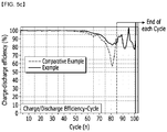
- FIG. 5c shows the charge/discharge efficiency according to the cycles of each battery.
- the lithium metal battery of Comparative Example 2 was designed such that the second pores (pores having relatively large diameters) of the anode current collector (Preparation Example 1) face a lithium metal layer, and the first pores (pores having relatively small diameters) of the anode current collector face a separator.
- the first pores facing a separator may be blocked because lithium ions cannot smoothly enter during the repeated charge/discharge process of the lithium metal battery.
- the lithium metal battery of Example 2 was designed such that the second pores (pore having relatively large diameters) of the anode current collector (Preparation Example 1) face a separator, and the first pores (pores having relatively small diameters) of the anode current collector face a lithium metal layer.
- the second pores facing a separator provide a wide entrance where lithium ions (specifically, lithium ions derived from the electrolyte impregnated in the separator) can easily enter.
- the lithium ions entering the wide entrance (the second pores) pass through the holes of the anode current collector to move to a lithium metal layer.
- the holes having gradually decreasing diameters while penetrating inside the anode current collector from the wide entrance (the second pores) facing a separator to the narrow entrance (the first pores) facing a lithium metal layer, provide various directions and sufficient spaces where lithium ions can enter, local blocking can be inhibited during the repeated charge/discharge processes of a lithium metal battery.
- a lithium metal battery is designed as in Example 2 using the anode current collector of Preparation Example 1, reversibility of a lithium metal anode can be secured, and the cycle life characteristic of a lithium metal battery can be improved.
- FIG. 6a shows the charge capacity according to the cycles of each battery
- FIG. 6b shows the discharge capacity according to the cycles of each battery.
Landscapes
- Chemical & Material Sciences (AREA)
- Chemical Kinetics & Catalysis (AREA)
- Electrochemistry (AREA)
- General Chemical & Material Sciences (AREA)
- Engineering & Computer Science (AREA)
- Materials Engineering (AREA)
- Manufacturing & Machinery (AREA)
- Battery Electrode And Active Subsutance (AREA)
- Secondary Cells (AREA)
- Cell Electrode Carriers And Collectors (AREA)
Applications Claiming Priority (3)
| Application Number | Priority Date | Filing Date | Title |
|---|---|---|---|
| KR20170178759 | 2017-12-22 | ||
| KR1020180166735A KR20190076890A (ko) | 2017-12-22 | 2018-12-20 | 리튬 메탈 전지용 음극 및 이를 포함하는 리튬 메탈 전지 |
| PCT/KR2018/016500 WO2019125064A1 (ko) | 2017-12-22 | 2018-12-21 | 리튬 메탈 전지용 음극 및 이를 포함하는 리튬 메탈 전지 |
Publications (2)
| Publication Number | Publication Date |
|---|---|
| EP3598546A1 true EP3598546A1 (de) | 2020-01-22 |
| EP3598546A4 EP3598546A4 (de) | 2020-06-17 |
Family
ID=67258651
Family Applications (1)
| Application Number | Title | Priority Date | Filing Date |
|---|---|---|---|
| EP18891822.1A Pending EP3598546A4 (de) | 2017-12-22 | 2018-12-21 | Negativelektrode für lithium-metall-batterie und lithium-metall-batterie, dieselbe umfassend |
Country Status (3)
| Country | Link |
|---|---|
| US (1) | US12009522B2 (de) |
| EP (1) | EP3598546A4 (de) |
| KR (2) | KR20190076890A (de) |
Families Citing this family (4)
| Publication number | Priority date | Publication date | Assignee | Title |
|---|---|---|---|---|
| AU2021273919A1 (en) | 2020-05-22 | 2022-10-06 | Duracell U.S. Operations, Inc. | Seal assembly for a battery cell |
| KR102459358B1 (ko) * | 2020-08-13 | 2022-10-28 | 한국과학기술원 | 3차원 나노구조에 의한 활물질/전류집전체 물질의 비율 구배를 갖는 다공성 복합 전극, 그 제조 방법 및 이를 포함하는 이차 전지 |
| KR102630743B1 (ko) | 2022-01-12 | 2024-01-29 | 주식회사 엘지에너지솔루션 | 리튬 금속 음극 및 이를 포함하는 전기화학소자 |
| CN116504991B (zh) * | 2023-05-10 | 2025-09-23 | 东北大学 | 一种整体导电的复合集流体薄膜 |
Family Cites Families (19)
| Publication number | Priority date | Publication date | Assignee | Title |
|---|---|---|---|---|
| JP4462509B2 (ja) | 1997-08-14 | 2010-05-12 | 日本製箔株式会社 | 二次電池用孔開き集電体及びその製造方法 |
| JPH1167218A (ja) | 1997-08-14 | 1999-03-09 | Nippon Foil Mfg Co Ltd | 二次電池に用いる孔開き集電体 |
| KR100447792B1 (ko) | 2002-09-30 | 2004-09-08 | 한국과학기술연구원 | 다공성의 3차원 집전체를 이용한 리튬전극, 그 제조방법및 리튬전지 |
| JP2007277641A (ja) * | 2006-04-07 | 2007-10-25 | Mitsui Mining & Smelting Co Ltd | 孔開き金属箔の製造方法及び孔開き金属箔 |
| JP4994205B2 (ja) | 2007-12-06 | 2012-08-08 | 三菱電機株式会社 | 電気二重層キャパシタ及びその製造方法 |
| JP2010015974A (ja) * | 2008-03-28 | 2010-01-21 | Fuji Heavy Ind Ltd | 電極の製造方法、蓄電デバイス、および中間積層材 |
| JP5539985B2 (ja) * | 2009-07-07 | 2014-07-02 | 東洋アルミニウム株式会社 | アルミニウム貫通箔 |
| CN102575322B (zh) * | 2009-09-30 | 2014-04-02 | 东洋铝株式会社 | 铝贯通箔及其制造方法 |
| KR101189257B1 (ko) | 2009-10-27 | 2012-10-09 | 경상대학교산학협력단 | 전극 및 그 제조 방법 |
| KR101338299B1 (ko) * | 2011-06-29 | 2013-12-09 | 주식회사 엘지화학 | 고전압용 이차전지 |
| JP2013069632A (ja) | 2011-09-26 | 2013-04-18 | Toyota Industries Corp | 二次電池又はキャパシタ用の集電体 |
| JP2013182810A (ja) | 2012-03-02 | 2013-09-12 | Tdk Corp | 集電体、およびそれを用いたリチウムイオン二次電池 |
| KR101598650B1 (ko) * | 2012-08-23 | 2016-03-03 | 주식회사 엘지화학 | 음극 및 이를 포함하는 고용량 리튬이차전지 |
| TWI528619B (zh) | 2014-07-16 | 2016-04-01 | 輝能科技股份有限公司 | 金屬鋰極板 |
| CN106795646B (zh) | 2014-10-14 | 2018-12-18 | 富士胶片株式会社 | 铝板和铝板的制造方法 |
| KR101850180B1 (ko) * | 2015-01-20 | 2018-04-18 | 주식회사 엘지화학 | 관통구가 천공되어 있는 집전체를 포함하는 이차전지 |
| CN107431236A (zh) | 2015-03-30 | 2017-12-01 | 日立化成株式会社 | 锂离子二次电池及其制造方法 |
| CN117558971A (zh) * | 2015-11-24 | 2024-02-13 | 锡安能量公司 | 离子传导化合物及其相关用途 |
| WO2017188021A1 (ja) | 2016-04-26 | 2017-11-02 | 日立マクセル株式会社 | 電気化学素子用電極およびリチウムイオン二次電池 |
-
2018
- 2018-12-20 KR KR1020180166735A patent/KR20190076890A/ko not_active Ceased
- 2018-12-21 US US16/500,633 patent/US12009522B2/en active Active
- 2018-12-21 EP EP18891822.1A patent/EP3598546A4/de active Pending
-
2021
- 2021-07-06 KR KR1020210088442A patent/KR102377302B1/ko active Active
Also Published As
| Publication number | Publication date |
|---|---|
| KR20190076890A (ko) | 2019-07-02 |
| KR102377302B1 (ko) | 2022-03-22 |
| KR20210087922A (ko) | 2021-07-13 |
| EP3598546A4 (de) | 2020-06-17 |
| US12009522B2 (en) | 2024-06-11 |
| US20200099058A1 (en) | 2020-03-26 |
Similar Documents
| Publication | Publication Date | Title |
|---|---|---|
| KR102328648B1 (ko) | 리튬 금속 전지용 음극, 이의 제조 방법, 및 이를 포함하는 리튬 금속 전지 | |
| US8734989B2 (en) | Negative electrode for rechargeable lithium battery and rechargeable lithium battery including the same | |
| US8906555B2 (en) | Negative active material for rechargeable lithium battery and rechargeable lithium battery comprising same | |
| US11581540B2 (en) | Negative electrode active material for rechargeable lithium battery, method for preparing the same, and negative electrode and rechargeable lithium battery including same | |
| US8349492B2 (en) | Negative electrode for rechargeable lithium battery, and rechargeable lithium battery including same | |
| US9012074B2 (en) | Electrode for lithium secondary battery and lithium secondary battery including same | |
| US9166220B2 (en) | Negative active material for rechargeable lithium battery, method of preparing the same and rechargeable lithium battery including the same | |
| KR102377302B1 (ko) | 리튬 메탈 전지용 음극 및 이를 포함하는 리튬 메탈 전지 | |
| US20090136847A1 (en) | Negative active material for rechargeable lithium battery, and method of preparing the same | |
| US12183948B2 (en) | Separator for secondary battery, manufacturing method therefor, and lithium secondary battery comprising same | |
| JP2014032964A (ja) | リチウム二次電池用負極活物質、その製造方法およびこれを含むリチウム二次電池 | |
| CN110462902B (zh) | 用于锂金属电池的阳极和包括该阳极的锂金属电池 | |
| EP3742527B1 (de) | Anode für eine lithiummetallbatterie, verfahren zur herstellung davon und lithiummetallbatterie damit | |
| US9496548B2 (en) | Negative active material for rechargeable lithium battery, method for preparing same, and rechargeable lithium battery including same | |
| US20240047764A1 (en) | Lithium-free secondary battery | |
| KR20090108317A (ko) | 리튬 이차 전지 및 그의 제조 방법 | |
| US9219264B2 (en) | Separator for rechargeable lithium battery and rechargeable lithium battery including the same | |
| KR101815712B1 (ko) | 리튬 이차 전지용 세퍼레이터 및 이를 포함하는 리튬 이차 전지 | |
| US20220393256A1 (en) | Lithium metal battery and manufacturing method thereof | |
| KR102425003B1 (ko) | 리튬 이차 전지 | |
| JP7384528B2 (ja) | 二次電池用負極、その製造方法、およびそれを含むリチウム金属二次電池 | |
| KR20240047714A (ko) | 리튬 금속 전지용 음극, 이의 제조 방법, 및 이를 포함하는 리튬 금속 전지 |
Legal Events
| Date | Code | Title | Description |
|---|---|---|---|
| STAA | Information on the status of an ep patent application or granted ep patent |
Free format text: STATUS: THE INTERNATIONAL PUBLICATION HAS BEEN MADE |
|
| PUAI | Public reference made under article 153(3) epc to a published international application that has entered the european phase |
Free format text: ORIGINAL CODE: 0009012 |
|
| STAA | Information on the status of an ep patent application or granted ep patent |
Free format text: STATUS: REQUEST FOR EXAMINATION WAS MADE |
|
| 17P | Request for examination filed |
Effective date: 20191015 |
|
| AK | Designated contracting states |
Kind code of ref document: A1 Designated state(s): AL AT BE BG CH CY CZ DE DK EE ES FI FR GB GR HR HU IE IS IT LI LT LU LV MC MK MT NL NO PL PT RO RS SE SI SK SM TR |
|
| AX | Request for extension of the european patent |
Extension state: BA ME |
|
| A4 | Supplementary search report drawn up and despatched |
Effective date: 20200519 |
|
| RIC1 | Information provided on ipc code assigned before grant |
Ipc: H01M 4/66 20060101ALI20200513BHEP Ipc: H01M 10/052 20100101ALI20200513BHEP Ipc: H01M 4/70 20060101AFI20200513BHEP Ipc: H01M 4/134 20100101ALI20200513BHEP Ipc: H01M 4/74 20060101ALI20200513BHEP |
|
| DAV | Request for validation of the european patent (deleted) | ||
| DAX | Request for extension of the european patent (deleted) | ||
| RAP1 | Party data changed (applicant data changed or rights of an application transferred) |
Owner name: LG ENERGY SOLUTION LTD. |
|
| RAP3 | Party data changed (applicant data changed or rights of an application transferred) |
Owner name: LG ENERGY SOLUTION, LTD. |
|
| STAA | Information on the status of an ep patent application or granted ep patent |
Free format text: STATUS: EXAMINATION IS IN PROGRESS |
|
| 17Q | First examination report despatched |
Effective date: 20220414 |
|
| REG | Reference to a national code |
Ref country code: DE Ref legal event code: R079 Free format text: PREVIOUS MAIN CLASS: H01M0004700000 Ipc: H01M0004040000 |
|
| GRAP | Despatch of communication of intention to grant a patent |
Free format text: ORIGINAL CODE: EPIDOSNIGR1 |
|
| STAA | Information on the status of an ep patent application or granted ep patent |
Free format text: STATUS: GRANT OF PATENT IS INTENDED |
|
| RIC1 | Information provided on ipc code assigned before grant |
Ipc: H01M 4/04 20060101AFI20251218BHEP Ipc: H01M 4/1395 20100101ALI20251218BHEP Ipc: H01M 4/38 20060101ALI20251218BHEP Ipc: H01M 10/052 20100101ALI20251218BHEP Ipc: H01M 4/134 20100101ALI20251218BHEP Ipc: H01M 4/66 20060101ALI20251218BHEP Ipc: H01M 4/74 20060101ALI20251218BHEP |
|
| INTG | Intention to grant announced |
Effective date: 20260114 |