EP3597992B1 - Faseroptische funkelnde sternenmuster mittels lichtmaschine und spezialisierter optik - Google Patents
Faseroptische funkelnde sternenmuster mittels lichtmaschine und spezialisierter optik Download PDFInfo
- Publication number
- EP3597992B1 EP3597992B1 EP19186825.6A EP19186825A EP3597992B1 EP 3597992 B1 EP3597992 B1 EP 3597992B1 EP 19186825 A EP19186825 A EP 19186825A EP 3597992 B1 EP3597992 B1 EP 3597992B1
- Authority
- EP
- European Patent Office
- Prior art keywords
- light
- panel
- vehicle
- ldu
- optical
- Prior art date
- Legal status (The legal status is an assumption and is not a legal conclusion. Google has not performed a legal analysis and makes no representation as to the accuracy of the status listed.)
- Active
Links
Images




Classifications
-
- A—HUMAN NECESSITIES
- A63—SPORTS; GAMES; AMUSEMENTS
- A63J—DEVICES FOR THEATRES, CIRCUSES, OR THE LIKE; CONJURING APPLIANCES OR THE LIKE
- A63J25/00—Equipment specially adapted for cinemas
-
- H—ELECTRICITY
- H05—ELECTRIC TECHNIQUES NOT OTHERWISE PROVIDED FOR
- H05B—ELECTRIC HEATING; ELECTRIC LIGHT SOURCES NOT OTHERWISE PROVIDED FOR; CIRCUIT ARRANGEMENTS FOR ELECTRIC LIGHT SOURCES, IN GENERAL
- H05B47/00—Circuit arrangements for operating light sources in general, i.e. where the type of light source is not relevant
- H05B47/10—Controlling the light source
- H05B47/155—Coordinated control of two or more light sources
-
- G—PHYSICS
- G02—OPTICS
- G02B—OPTICAL ELEMENTS, SYSTEMS OR APPARATUS
- G02B6/00—Light guides; Structural details of arrangements comprising light guides and other optical elements, e.g. couplings
- G02B6/0001—Light guides; Structural details of arrangements comprising light guides and other optical elements, e.g. couplings specially adapted for lighting devices or systems
- G02B6/0005—Light guides; Structural details of arrangements comprising light guides and other optical elements, e.g. couplings specially adapted for lighting devices or systems the light guides being of the fibre type
- G02B6/0008—Light guides; Structural details of arrangements comprising light guides and other optical elements, e.g. couplings specially adapted for lighting devices or systems the light guides being of the fibre type the light being emitted at the end of the fibre
-
- F—MECHANICAL ENGINEERING; LIGHTING; HEATING; WEAPONS; BLASTING
- F21—LIGHTING
- F21S—NON-PORTABLE LIGHTING DEVICES; SYSTEMS THEREOF; VEHICLE LIGHTING DEVICES SPECIALLY ADAPTED FOR VEHICLE EXTERIORS
- F21S8/00—Lighting devices intended for fixed installation
-
- B—PERFORMING OPERATIONS; TRANSPORTING
- B60—VEHICLES IN GENERAL
- B60Q—ARRANGEMENT OF SIGNALLING OR LIGHTING DEVICES, THE MOUNTING OR SUPPORTING THEREOF OR CIRCUITS THEREFOR, FOR VEHICLES IN GENERAL
- B60Q3/00—Arrangement of lighting devices for vehicle interiors; Lighting devices specially adapted for vehicle interiors
- B60Q3/40—Arrangement of lighting devices for vehicle interiors; Lighting devices specially adapted for vehicle interiors specially adapted for specific vehicle types
- B60Q3/41—Arrangement of lighting devices for vehicle interiors; Lighting devices specially adapted for vehicle interiors specially adapted for specific vehicle types for mass transit vehicles, e.g. buses
- B60Q3/43—General lighting
-
- B—PERFORMING OPERATIONS; TRANSPORTING
- B60—VEHICLES IN GENERAL
- B60Q—ARRANGEMENT OF SIGNALLING OR LIGHTING DEVICES, THE MOUNTING OR SUPPORTING THEREOF OR CIRCUITS THEREFOR, FOR VEHICLES IN GENERAL
- B60Q3/00—Arrangement of lighting devices for vehicle interiors; Lighting devices specially adapted for vehicle interiors
- B60Q3/60—Arrangement of lighting devices for vehicle interiors; Lighting devices specially adapted for vehicle interiors characterised by optical aspects
- B60Q3/62—Arrangement of lighting devices for vehicle interiors; Lighting devices specially adapted for vehicle interiors characterised by optical aspects using light guides
-
- F—MECHANICAL ENGINEERING; LIGHTING; HEATING; WEAPONS; BLASTING
- F21—LIGHTING
- F21V—FUNCTIONAL FEATURES OR DETAILS OF LIGHTING DEVICES OR SYSTEMS THEREOF; STRUCTURAL COMBINATIONS OF LIGHTING DEVICES WITH OTHER ARTICLES, NOT OTHERWISE PROVIDED FOR
- F21V5/00—Refractors for light sources
- F21V5/04—Refractors for light sources of lens shape
-
- F—MECHANICAL ENGINEERING; LIGHTING; HEATING; WEAPONS; BLASTING
- F21—LIGHTING
- F21V—FUNCTIONAL FEATURES OR DETAILS OF LIGHTING DEVICES OR SYSTEMS THEREOF; STRUCTURAL COMBINATIONS OF LIGHTING DEVICES WITH OTHER ARTICLES, NOT OTHERWISE PROVIDED FOR
- F21V5/00—Refractors for light sources
- F21V5/04—Refractors for light sources of lens shape
- F21V5/043—Refractors for light sources of lens shape the lens having cylindrical faces, e.g. rod lenses, toric lenses
-
- B—PERFORMING OPERATIONS; TRANSPORTING
- B64—AIRCRAFT; AVIATION; COSMONAUTICS
- B64D—EQUIPMENT FOR FITTING IN OR TO AIRCRAFT; FLIGHT SUITS; PARACHUTES; ARRANGEMENT OR MOUNTING OF POWER PLANTS OR PROPULSION TRANSMISSIONS IN AIRCRAFT
- B64D11/00—Passenger or crew accommodation; Flight-deck installations not otherwise provided for
- B64D2011/0038—Illumination systems for cabins as a whole
-
- B—PERFORMING OPERATIONS; TRANSPORTING
- B64—AIRCRAFT; AVIATION; COSMONAUTICS
- B64D—EQUIPMENT FOR FITTING IN OR TO AIRCRAFT; FLIGHT SUITS; PARACHUTES; ARRANGEMENT OR MOUNTING OF POWER PLANTS OR PROPULSION TRANSMISSIONS IN AIRCRAFT
- B64D2203/00—Aircraft or airfield lights using LEDs
-
- B—PERFORMING OPERATIONS; TRANSPORTING
- B64—AIRCRAFT; AVIATION; COSMONAUTICS
- B64D—EQUIPMENT FOR FITTING IN OR TO AIRCRAFT; FLIGHT SUITS; PARACHUTES; ARRANGEMENT OR MOUNTING OF POWER PLANTS OR PROPULSION TRANSMISSIONS IN AIRCRAFT
- B64D47/00—Equipment not otherwise provided for
- B64D47/02—Arrangements or adaptations of signal or lighting devices
- B64D47/04—Arrangements or adaptations of signal or lighting devices the lighting devices being primarily intended to illuminate the way ahead
-
- F—MECHANICAL ENGINEERING; LIGHTING; HEATING; WEAPONS; BLASTING
- F21—LIGHTING
- F21S—NON-PORTABLE LIGHTING DEVICES; SYSTEMS THEREOF; VEHICLE LIGHTING DEVICES SPECIALLY ADAPTED FOR VEHICLE EXTERIORS
- F21S10/00—Lighting devices or systems producing a varying lighting effect
- F21S10/005—Lighting devices or systems producing a varying lighting effect using light guides
-
- F—MECHANICAL ENGINEERING; LIGHTING; HEATING; WEAPONS; BLASTING
- F21—LIGHTING
- F21S—NON-PORTABLE LIGHTING DEVICES; SYSTEMS THEREOF; VEHICLE LIGHTING DEVICES SPECIALLY ADAPTED FOR VEHICLE EXTERIORS
- F21S8/00—Lighting devices intended for fixed installation
- F21S8/02—Lighting devices intended for fixed installation of recess-mounted type, e.g. downlighters
-
- F—MECHANICAL ENGINEERING; LIGHTING; HEATING; WEAPONS; BLASTING
- F21—LIGHTING
- F21V—FUNCTIONAL FEATURES OR DETAILS OF LIGHTING DEVICES OR SYSTEMS THEREOF; STRUCTURAL COMBINATIONS OF LIGHTING DEVICES WITH OTHER ARTICLES, NOT OTHERWISE PROVIDED FOR
- F21V2200/00—Use of light guides, e.g. fibre optic devices, in lighting devices or systems
- F21V2200/10—Use of light guides, e.g. fibre optic devices, in lighting devices or systems of light guides of the optical fibres type
-
- F—MECHANICAL ENGINEERING; LIGHTING; HEATING; WEAPONS; BLASTING
- F21—LIGHTING
- F21V—FUNCTIONAL FEATURES OR DETAILS OF LIGHTING DEVICES OR SYSTEMS THEREOF; STRUCTURAL COMBINATIONS OF LIGHTING DEVICES WITH OTHER ARTICLES, NOT OTHERWISE PROVIDED FOR
- F21V2200/00—Use of light guides, e.g. fibre optic devices, in lighting devices or systems
- F21V2200/10—Use of light guides, e.g. fibre optic devices, in lighting devices or systems of light guides of the optical fibres type
- F21V2200/13—Use of light guides, e.g. fibre optic devices, in lighting devices or systems of light guides of the optical fibres type the light being emitted at the end of the guide
-
- F—MECHANICAL ENGINEERING; LIGHTING; HEATING; WEAPONS; BLASTING
- F21—LIGHTING
- F21V—FUNCTIONAL FEATURES OR DETAILS OF LIGHTING DEVICES OR SYSTEMS THEREOF; STRUCTURAL COMBINATIONS OF LIGHTING DEVICES WITH OTHER ARTICLES, NOT OTHERWISE PROVIDED FOR
- F21V33/00—Structural combinations of lighting devices with other articles, not otherwise provided for
- F21V33/006—General building constructions or finishing work for buildings, e.g. roofs, gutters, stairs or floors; Garden equipment; Sunshades or parasols
-
- F—MECHANICAL ENGINEERING; LIGHTING; HEATING; WEAPONS; BLASTING
- F21—LIGHTING
- F21W—INDEXING SCHEME ASSOCIATED WITH SUBCLASSES F21K, F21L, F21S and F21V, RELATING TO USES OR APPLICATIONS OF LIGHTING DEVICES OR SYSTEMS
- F21W2121/00—Use or application of lighting devices or systems for decorative purposes, not provided for in codes F21W2102/00 – F21W2107/00
- F21W2121/008—Use or application of lighting devices or systems for decorative purposes, not provided for in codes F21W2102/00 – F21W2107/00 for simulation of a starry sky or firmament
-
- F—MECHANICAL ENGINEERING; LIGHTING; HEATING; WEAPONS; BLASTING
- F21—LIGHTING
- F21W—INDEXING SCHEME ASSOCIATED WITH SUBCLASSES F21K, F21L, F21S and F21V, RELATING TO USES OR APPLICATIONS OF LIGHTING DEVICES OR SYSTEMS
- F21W2131/00—Use or application of lighting devices or systems not provided for in codes F21W2102/00-F21W2121/00
- F21W2131/40—Lighting for industrial, commercial, recreational or military use
- F21W2131/406—Lighting for industrial, commercial, recreational or military use for theatres, stages or film studios
-
- F—MECHANICAL ENGINEERING; LIGHTING; HEATING; WEAPONS; BLASTING
- F21—LIGHTING
- F21Y—INDEXING SCHEME ASSOCIATED WITH SUBCLASSES F21K, F21L, F21S and F21V, RELATING TO THE FORM OR THE KIND OF THE LIGHT SOURCES OR OF THE COLOUR OF THE LIGHT EMITTED
- F21Y2115/00—Light-generating elements of semiconductor light sources
- F21Y2115/10—Light-emitting diodes [LED]
-
- G—PHYSICS
- G09—EDUCATION; CRYPTOGRAPHY; DISPLAY; ADVERTISING; SEALS
- G09F—DISPLAYING; ADVERTISING; SIGNS; LABELS OR NAME-PLATES; SEALS
- G09F9/00—Indicating arrangements for variable information in which the information is built-up on a support by selection or combination of individual elements
- G09F9/30—Indicating arrangements for variable information in which the information is built-up on a support by selection or combination of individual elements in which the desired character or characters are formed by combining individual elements
- G09F9/305—Indicating arrangements for variable information in which the information is built-up on a support by selection or combination of individual elements in which the desired character or characters are formed by combining individual elements being the ends of optical fibres
Definitions
- the present disclosure relates to lighting panels.
- it relates to fiber optic lighting panels that produce twinkling star patterns by means of a light engine and specialized optics.
- Passenger aircraft that operate over long distances during the night typically include interior lighting arrangements that provide substantially reduced ambient light so that passengers can sleep comfortably, but which is still bright enough to enable those passengers who choose not to sleep to move about the cabin safely.
- interior lighting arrangements that provide substantially reduced ambient light so that passengers can sleep comfortably, but which is still bright enough to enable those passengers who choose not to sleep to move about the cabin safely.
- some models of the Boeing 777 passenger jet incorporate ceiling panels that incorporate light emitting diodes (LEDs) that are arranged to blink in random patterns against a dark background, which in an ambient light condition, gives a relaxing, soporific appearance of a starry nighttime sky, and hence, is referred to as a "starry sky" ceiling lighting arrangement.
- LEDs light emitting diodes
- a starry skies ceiling feature e.g., a starry skies ceiling panel
- a starry skies ceiling panel employ individual LEDs for each of the many stars in the panel.
- the manufacture of each of these panels is performed manually by drilling holes in the panel for the LEDs, inserting the LEDs into the drilled holes in the panel, and manually routing the wires that are attached to the LEDs along the back of the panel. This procedure is very labor intensive.
- SLC star light controller
- US5101466 states in its abstract: there is disclosed a light transmitting display assembly provided with a source of electromagnetic radiation in the visible spectrum and comprised of a display board containing information and formed with channels into which ends of optical fibers of an optical fiber bundle are selectively positioned and after positioning the surface of the display board is coated with microbeads wherein the source of electromagnetic radiation is directed into the other ends of the optical fibers of the optical fiber bundle to provide a light transmitting display assembly capable of wide angle viewing.
- US2004057251 states in its abstract: a decorative dome with controlled light enhancement consisting of a substantially concave structure having opposed front and rear faces and a plurality of apertures extending therethrough, for receipt of a plurality of optical fibers, extending between the interior surface of the concave structure, to a plurality of light emitting diodes ("LEDs") mounted in a junction box mounted on the outer periphery of the rear face of the concave structure.
- the junction box also contains a control circuit for varying the duration and intensity of the plurality of LEDs, with the junction box constructed so as to dissipate heat generated by the LEDs.
- the LED's direct light into the receiving end of each said optical fibers such that light from the respective LEDs are directed through the optical fibers and from the emitting ends of the optical fibers at the front face of the concave structure.
- the plurality of apertures on the front face of the concave structure are arranged in a selected patent discernable by a viewer.
- KR20110129590 A states in its abstract: a decoration block having optical fiber comprises an installation box, a main body, multiple optical fibers, and a fixing member.
- a decoration line accomplishing the character or patterns of specified formation is formed in the exterior of the main body.
- Multiple front end parts are installed along the decoration line formed in the main body at a regular interval.
- the multiple optical fibers have lights on the external light generation member in order to illuminate.
- the fixing member fixes the tip-end part of the optical fiber on the decoration line.
- US2011157557 states according to its abstract: an area projection system for reproducing a visual signal on a surface, comprising a light source, a fibre element comprising a plurality of light guide elements, a carrier element and imaging optics, wherein the fibre element comprises a first end and a second end, wherein the first end of the fibre element is arranged on the light source and the second end of the fibre element is arranged on the carrier element, wherein the imaging optics are arranged on the second end of the fibre element, wherein the area projection system is adapted to transmit a visual signal from the light source to the fibre element and subsequently to the imaging optics, and wherein the imaging optics are adapted to reproduce the visual signal on a surface.
- US2015008282 states according to its abstract: a display device for an aircraft cabin, comprising a display adapted to display a plurality of stars.
- a further aspect of the invention is an aircraft cabin comprising such a display device and an aircraft cabin wall compartment comprising a plurality of wall sections and a plurality of light emitting means for individually illuminating each wall section, wherein said wall sections and said light emitting means form such a display device.
- said display is adapted to display a plurality of stars.
- the present disclosure relates to a method, system, and apparatus for fiber optic lighting panels that produce twinkling star patterns by means of a light engine and specialized optics.
- a panel for creating a lighting scene according to claim 1.
- Optional features are set out in claims 2 to 7.
- a panel for creating a lighted scene comprises a substrate comprising a first surface, a second surface spaced from the first surface, and a plurality of apertures through the first and second surfaces.
- the panel further comprises a plurality of optical lenses.
- An optical lens of the plurality of optical lenses is disposed on the first surface within each of the apertures.
- the panel comprises a light distribution unit (LDU) comprising a plurality of light sources coupled to the second surface.
- the panel comprises a bundle of optical fibers coupled to each of the light sources, where each of the optical fibers is in communication with a different one of the plurality of optical lenses for transferring light emitted by the light sources to create the lighted scene.
- LDU light distribution unit
- the substrate is configured to be mounted to an interior of a vehicle.
- the vehicle is an airborne vehicle (e.g., an aircraft or space plane), a terrestrial vehicle (e.g., a truck, bus, or train), or a marine vehicle (e.g., a boat or submarine).
- each of the optical lenses is convex in shape. In some examples, not forming part of the invention to which this patent relates, each of the optical lenses allows for light to be observed from up to a ninety (90) degree viewing angle.
- the light sources are light emitting diodes (LEDs) with multiple different color wavelengths.
- each of the light sources illuminates a different illumination pattern.
- one of the illumination patterns is a slow twinkling illumination pattern, a fast twinkling illumination pattern, a constant bright illumination pattern, or a constant dim illumination pattern.
- the bundle of optical fibers is coupled to each of the light sources via a light pipe.
- each of the light sources is individually controllable.
- a method for operating a panel, as above, for creating a lighted scene comprises commanding, by a light distribution unit (LDU) of the panel, at least one light source within the LDU to illuminate according to a current operational phase.
- the method further comprises illuminating light, by at least one light source, according to the current operational phase, where the light is illuminated through optical fibers coupled to the at least one light source to create the lighted scene.
- LDU light distribution unit
- the method further comprises processing, by a cabin services system (CSS), operational data to determine the current operational phase.
- CCS cabin services system
- the operational data is flight data.
- the method further comprises commanding, by a CSS, a star light controller (SLC) to control the LDU of the panel according to the current operational phase.
- a CSS a star light controller
- the current operational phase is a current flight phase.
- the systems and apparatus disclosed herein provide an operative system for fiber optic lighting panels that produce twinkling star patterns by means of a light engine and specialized optics.
- the system of the present disclosure utilizes fiber optics to generate a starry skies ceiling feature (e.g., starry skies ceiling panel) comprises a light distribution unit (LDU), which includes multiple individually controlled LED light sources, and comprises a plurality of optical fibers coupled to the LDU for transferring emitted light throughout the panel.
- LDU light distribution unit
- starry skies ceiling feature e.g., the starry skies ceiling panel
- individual LEDs for each "star” in the panel are difficult to manufacture, typically have long lead times, and require the technician to endure repetitive motions to install the many small LEDs throughout the panel.
- the design of the disclosed starry skies ceiling panel reduces the number of LEDs required, and eliminates much of the associated wiring.
- the use of fiber optics and use of an LDU to drive the optical fibers in the disclosed starry skies ceiling feature greatly lessens the weight and power consumption of the ceiling panels.
- the fiber optics design allows for efficient installation and eliminates repetitive motion injuries that may occur from installing the individual LEDs used in the existing solutions.
- the lenses used for the optics in the disclosed starry skies ceiling panel creates the luminous perception of each of the stars illuminating brighter across a greater degree of viewing area and, therefore, makes the stars appear more realistic.
- the control of the starry skies ceiling feature by means of the different phases of flight i.e. the starry skies ceiling feature is controlled to be brighter for a daytime flight phase than for a nighttime flight phase) saves time and energy for the flight attendants so that they do not need to manually switch on and off the different stars of the starry skies ceiling feature during the different phases of flight.
- the fiber optics design for the panel may be in a unique pattern to emulate stars in the sky, or to specifically emulate a particular part of the night sky (i.e. to emulate particular constellations).
- the use of fiber optics allows for multiple channels to be utilized to generate an aesthetically realistic star pattern or constellation.
- the use of the fiber optics compared to traditional electrical wiring which is used by the current solutions, greatly decreases the weight and power consumption of each individual panel.
- the use of a LDU which in some embodiments comprises four channels, decreases the weight on each individual panel and greatly reduces power consumption.
- Currently used conventional solutions employ multiple SLCs on each panel, where each SLC consumes 3500 W in order to drive approximately 60 to 90 LEDs installed on the panel.
- each LDU consumes 3500 W in order to drive approximately 60 to 90 LEDs installed on the panel.
- only one LDU is needed on each panel, and a single LDU only consumes 4 W.
- the entire shipset e.g., vehicle
- starry skies ceiling panels are driven by one SLC.
- a single LDU is capable of employing four LEDs of different wavelengths, where one LED may be a warm 2500 Kelvin (K) Correlated Color Temperature (CCT) LED, a second LED may be a neutral 4000K CCT LED, a third LED may be a cool 5500K CCT LED, and a fourth LED may be a cold 6500K CCT LED.
- K Kelvin
- CCT Correlated Color Temperature
- This combination of four different types of LEDs closely simulates the star color differences that are physically observed in the nighttime sky.
- the four channels (from the four different LEDs) produce four states, which are: a dim state (constant dim), a bright state (constant bright), a twinkle slow state (slow twinkling), and a twinkle fast state (fast twinkling).
- the combined four different LEDs with their respective channels creates a closely accurate realistic representation of stars being closer or further away in the night sky and of the stars exhibiting different color intensities.
- the optical lenses employed by the disclosed system allow for a higher luminous perception at zero (0) degrees beneath the star panels and up to eighty-five (85) degrees of observation away from the star panel. This allows passengers to enjoy the star features of a single panel even when being located many rows away from that particular panel.
- the employed lens has a tip that allows for this distribution of light.
- the mood lighting control of the starry skies panels allows for the flight attendants to not have to manually manage the star panels on/off function during the different phases of flight. For example, at the beginning of a sleep phase during flight, communication triggers from the airplane cabin services system (CSS) will automatically trigger the starry skies ceiling panels to set their various four channel states appropriately to display a nighttime sky sleep scene. As such, this design allows for the time and energy that would be normally used by the flight attendants to manage the starry skies panels to be used for the needs of the passengers instead.
- CCS airplane cabin services system
- the disclosed starry skies ceiling feature is directed to a system for enhancing passenger experience during flight. More specifically, the system provides a twinkling star pattern on the ceiling of an aircraft.
- the disclosed system comprises a panel configured to be installed in the upper section of the passenger area of an aircraft.
- the panel comprises a substrate having a first and second surface spaced from one another, and defines a plurality of apertures through the surfaces. The apertures are randomly positioned throughout the panel.
- Optical lenses presenting a convex surface are disposed in each of the apertures, on the first surface within the passenger area.
- An LDU including multiple LEDs is disposed on a second surface of the panel, which is concealed from view within the passenger area of the aircraft.
- Each of the LEDs emits a different illumination pattern (e.g., slow twinkling, fast twinkling, constant bright, constant dim).
- a light pipe is coupled to each LED for directing the light emitted therefrom.
- a bundle of optical fibers is coupled to each light pipe, and optical lenses are coupled to the optical fibers for directing light from the light source and through the optical lenses.
- the optical lenses are convex in shape to allow for light to carry through and illuminate out of the lens tip.
- Each of the LEDs can be individually controlled for customizing the lighting scene (e.g., for customizing cabin mood lighting).
- the fiber optic cables are configured in a substantially random pattern along the substrate for mixing the various illumination patterns to create a realistic starry pattern within the passenger area of the vehicle.
- Examples not forming part of the invention to which this patent relates may be described herein in terms of functional and/or logical components and various processing steps. It should be appreciated that such components may be realized by any number of hardware, software, and/or firmware components configured to perform the specified functions.
- an example not forming part of the invention to which this patent relates may employ various integrated circuit components (e.g., memory elements, digital signal processing elements, logic elements, look-up tables, or the like), which may carry out a variety of functions under the control of one or more processors, microprocessors, or other control devices.
- integrated circuit components e.g., memory elements, digital signal processing elements, logic elements, look-up tables, or the like
- examples not forming part of the invention to which this patent relates may be practiced in conjunction with other components, and that the systems described herein are merely examples not forming part of the invention to which this patent relates.
- FIG. 1 is a diagram 100 showing a cross-sectional view of an exemplary vehicle (e.g., aircraft) 120 that employs the disclosed starry skies ceiling panel 110, in accordance with at least one embodiment of the present disclosure.
- vehicle 120 depicted as an aircraft.
- the disclosed panel 110 may be employed by various different types of vehicles 120 other than an aircraft including, but not limited to, other type of airborne vehicles (e.g., a space plane), terrestrial vehicles (e.g., trucks, buses, and trains), and marine vehicles (e.g., boats or submarines).
- the disclosed panel 110 may be employed for non-vehicle applications including, but not limited to, dance halls, shopping malls, theaters, or residential ceilings.
- two starry skies ceiling panels 110 are shown to be installed within the interior of the vehicle (e.g., aircraft) 120.
- the panels 110 are installed on the ceiling of the vehicle 120 just above the luggage storage areas 130 and above the aisles 140 of the vehicle 120. It should be noted that in other embodiments, the panels 110 may be installed in various different locations of the vehicle 120 other than the locations as shown in FIG. 1 .
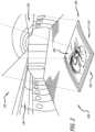
- FIG. 2 is a diagram 200 showing how the disclosed starry skies ceiling panel 110 is mounted within the exemplary vehicle 120 of FIG. 1 , in accordance with at least one embodiment of the present disclosure.
- this figure shows an exploded view of the panel 110 being pulled off of its mounting location on the ceiling of the interior of the vehicle 120.
- the panel 110 comprises a substrate 230, which comprises a first surface 210 that can be viewed from the interior of the vehicle 120 when the panel is mounted within the vehicle 120, and a second surface 220 that cannot be viewed from the interior of the vehicle 120 when the panel is mounted within the vehicle 120.
- This exploded view shows the details of the second surface 220 of the panel 110.
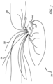
- FIG. 3 is a diagram 300 showing details of components of the disclosed starry skies ceiling panel 110, in accordance with at least one embodiment of the present disclosure.
- the components include a light distribution unit (LDU) 310, a power line 340 connected to the LDU 310 to deliver power the LDU 310, and a communications wire 350 connected to the LDU 310 to deliver control commands to the LDU 310.
- LDU light distribution unit
- four bundles 320 of optical fibers 330 are shown to be coupled to the LDU 310. The loose ends of each of the optical fibers 330 illuminate light that creates a lighted scene on the panel 110.
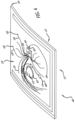
- FIG. 4 is a diagram 400 showing details how the components of the disclosed starry skies ceiling panel 110 are arranged on the panel 110, in accordance with at least one embodiment of the present disclosure.
- a bottom surface of the LDU 310 is coupled (e.g., mounted) to the second surface 220 of the panel 110.
- An optical device (refer to 620 of FIG. 6 ) comprising an optical lens (refer to 610 of FIG. 6 ) is coupled to the loose end of each optical fiber 330.
- the substrate 230 of the panel 110 comprises a plurality of apertures 430 (also refer to 430 of FIG. 6 ) through the first surface 210 and the second surface 220.
- the optical lenses (refer to 610 of FIG. 6 ) coupled to the loose ends of the optical fiber 330 are disposed within the first surface 210 the apertures 430.
- the optical fibers 330 are configured in a substantially random pattern in the apertures 430 of the substrate 230 of the panel 110 for mixing various illumination patterns to create a realistic starry pattern within the passenger area of the vehicle 120.
- the substrate 230 of the panel 110 comprises a large aperture 420 for a speaker 410.
- the large aperture 420 is covered with a light material (e.g., a fabric) to cover the aperture 420 and to also allow for sound waves emitted from the speaker 410 to radiate through the aperture 420 to the first side 210 of the panel 110.
- a power line 440 is connected to the speaker 410 to deliver power the speaker 410.
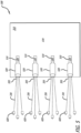
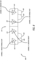
- FIG. 5 is a diagram 500 showing details of the light distribution unit (LDU) 310 of the disclosed starry skies ceiling panel 110, in accordance with at least one embodiment of the present disclosure.
- the LDU 310 is shown to comprise four light sources 510.
- the light sources 510 are light emitting diodes (LEDs) with multiple different color wavelengths.
- the LDU 310 may comprise more or less light sources 510 than four light sources 510 as is shown in FIG. 5 .
- other types of lighting devices other than LEDs may be employed for the light sources 510 of the LDU 310.
- Each of the light sources 510 can be individually controlled by the LDU 310 for customizing the lighting scene (e.g., for customizing cabin mood lighting). Also, each light source 510 may illuminate a different illumination pattern, such as a slow twinkling illumination pattern, a fast twinkling illumination pattern, a constant bright illumination pattern, and/or a constant dim illumination pattern.
- a different illumination pattern such as a slow twinkling illumination pattern, a fast twinkling illumination pattern, a constant bright illumination pattern, and/or a constant dim illumination pattern.
- one light source 510 may employ a warm 2500 Kelvin (K) Correlated Color Temperature (CCT) LED to illuminate a slow twinkling illumination pattern
- second light source 510 may employ a cold 10,000K CCT LED to illuminate a constant bright illumination pattern
- third light source 510 may employ a cool 5500K CCT LED to illuminate a fast twinkling illumination pattern
- a fourth light source 510 may employ a neutral 3500K CCT LED to illuminate a constant dim illumination pattern.
- different light sources 510 may be activated (e.g., illuminated) or inactivated (e.g., not illuminated).
- only the channel 1 and channel 4 may be activated to illuminate a slow twinkling illumination pattern and a constant dim illumination pattern, respectively.
- only channel 2 and channel 3 may be activated to illuminate a constant bright illumination pattern and a fast twinkling illumination pattern, respectively.
- the LDU 310 is shown to comprises light pipes (e.g., a lightguide) 520.
- a light pipe 520 is coupled to each light source 510 for directing the light emitted therefrom.
- a bundle of optical fibers 320 is coupled to each light pipe 520, and optical devices 620 (also refer to FIG. 6 ) are coupled to the optical fibers 330 for directing light from the light source 510 and through the optical lenses (refer to 610 of FIG. 6 ) of the optical devices 620.
- FIG. 6 is a diagram 600 showing details of how each optical lens 610 is disposed within the disclosed starry skies ceiling panel 110, in accordance with at least one examples not forming part of the invention to which this patent relates.
- an optical device 620 is coupled to the end of an optical fiber 330.
- the optical device 620 comprises a bushing 640, an optical insert 630, and an optical lens 610.
- an optical lens 610 is coupled to the end of the optical fiber 330 via the optical device 620.
- different types of optical devices other than the optical device 620 as shown in FIG. 6 may be employed for the optical device 620 of the disclosed panel 110.
- the substrate 230 of the panel 110 comprises an aperture 430 through the first surface 210 and the second surface 220.
- the optical lens 610 coupled to the end of the optical fiber 330 is disposed within the first surface 210 the aperture 430.
- the optical device 620 coupled to the optical fiber 330 directs light 650 from the light source (refer to 510 of FIG. 5 ) and through the optical lens 610.
- the optical lens 610 is convex in shape to allow for light 650 to be observed from up to a ninety (90) degree viewing angle on the second side of the substrate 230.
- FIG. 7 is a diagram 700 showing details of an exemplary optical lens 610 that may be employed for each of the optical lenses 610 of disclosed starry skies ceiling panel 110, in accordance with at least one embodiment of the present disclosure.
- the exemplary lens 610 is shown to be convex in shape. It should be noted that in other examples not forming part of the invention to which this patent relates, the optical lens 610 may be of a different shape than convex in shape as is shown in FIG. 7 .
- FIG. 8 is a diagram 800 showing the side view of the LDU 310 of the disclosed starry skies ceiling panel 110, in accordance with at least one embodiment of the present disclosure.
- ports 810 for the optical fibers are shown to be located on the side of the LDU 310.
- Bundles of optical fibers are coupled to the LDU 310 via the ports 810.
- the LDU 310 is shown to comprise several mounting feet 820, which may be used to couple (e.g., to mount) the LDU 310 to the second side 220 of the substrate 230 of the panel 110.
- FIG. 9 is a diagram 900 showing the disclosed system for the starry skies ceiling panel 110, in accordance with at least one embodiment of the present disclosure.
- the system is shown to comprise a cabin services system (CSS) 910 coupled to a star light controller (SLC) 920, which is coupled to a plurality of LDUs 310 of panels (refer to 110 of FIG. 2 ).
- the CSS 910 and the SLC 920 may be located within the electronics bay of the vehicle (e.g., aircraft) 120.
- the CSS 910 accesses and processes operational data (e.g., vehicle operational data, such as flight data) 930 to determine the current operational phase (e.g., the current flight phase of the aircraft, such as a nighttime phase or a daytime phase) of the vehicle (refer to 120 of FIG. 2 ).
- the CSS 910 commands the SLC 920 to control the LDUs 310 of each of the panels 110 according to the determined current operational phase.
- the LDUs 310 receive the commands from the SLC 920, the LDUs 310 individually command their different light sources (refer to 510 of FIG.
- the light sources 510 activate (e.g., illuminate) or inactivate (e.g., not illuminate) according to the current operational phase.
- the light sources 510 activate (e.g., illuminate) or inactivate (e.g., not illuminate) according to the current operational phase.
- the light sources 510 activate (e.g., illuminate) or inactivate (e.g., not illuminate) accordingly, light (refer to 650 of FIG. 6 ) is illuminated through the optical fibers (refer to 330 of FIG. 5 ) coupled to the optical devices (refer to 620 of FIG. 6 ) to create the lighted scene on the panel 110.
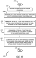
- FIG. 10 is a flow chart showing an example method 1000, not forming part of the invention to which this patent relates, for operating the disclosed starry skies ceiling panel 110, in accordance with at least one example not forming part of the invention to which this patent relates.
- the panel is mounted within an interior of a vehicle 1020.
- a cabin services system (CSS) processes operational data (e.g., flight data) to determine a current operational phase (e.g., current flight phase) 1030.
- the CSS then commands a star light controller (SLC) to control a light distribution unit (LDU) of the panel according to the current operational phase 1040.
- SCS star light controller
- LDU light distribution unit
- the LDU commands at least one light source (e.g., LED) of the LDU to illuminate according to the current operational phase 1050.
- the light source(s) then illuminates light according to the current operational phase, where the light is illuminated through optical fibers coupled to the optical devices to create a lighted scene 1060.
- the method 1000 ends 1070.
Landscapes
- Engineering & Computer Science (AREA)
- Physics & Mathematics (AREA)
- General Engineering & Computer Science (AREA)
- Mechanical Engineering (AREA)
- General Physics & Mathematics (AREA)
- Optics & Photonics (AREA)
- Aviation & Aerospace Engineering (AREA)
- Arrangements Of Lighting Devices For Vehicle Interiors, Mounting And Supporting Thereof, Circuits Therefore (AREA)
- Non-Portable Lighting Devices Or Systems Thereof (AREA)
- Circuit Arrangement For Electric Light Sources In General (AREA)
Claims (10)
- Paneel (110) zum Erzeugen einer beleuchteten Szene, wobei das Paneel (110) Folgendes aufweist:ein Substrat (230), das eine erste Fläche (210), eine zweite Fläche (220), die von der ersten Fläche (210) beabstandet ist, und mehrere Öffnungen (430) durch die erste und die zweite Fläche (210, 220) aufweist;mehrere optische Linsen (610), wobei eine optische Linse (610) der mehreren optischen Linsen (610) auf der ersten Fläche (210) innerhalb jeder der Öffnungen (430) angeordnet ist;eine Lichtverteilungseinheit (LDU, engl. light distribution unit) (310), die mehrere Lichtquellen (510) aufweist, die mit der zweiten Fläche (220) gekoppelt ist; undein Bündel (320) optischer Fasern (330), das mit jeder der Lichtquellen (510) gekoppelt ist, wobei jede der optischen Fasern (330) mit einer anderen der mehreren optischen Linsen (610) in Verbindung steht, um von den Lichtquellen (510) emittiertes Licht (650) zum Erzeugen der beleuchteten Szene zu übertragen,wobei das Substrat (230) dazu konfiguriert ist, im Inneren eines Fahrzeugs (120) montiert zu werden; undwobei die LDU (310) zu Folgendem konfiguriert ist:Empfangen eines Befehls von einer Sternenlichtsteuerung (SLC) (920), die mit einem Kabinenausrüstungssystem (CSS, engl. cabin services system) (910) des Fahrzeugs gekoppelt ist, das eine Betriebsphase des Fahrzeugs anzeigt, wobei die Betriebsphase des Fahrzeugs dazu konfiguriert ist, durch das CSS bestimmt zu werden, indem es auf Betriebsdaten des Fahrzeugs zugreift und diese verarbeitet, wobei die CSS (910) dazu konfiguriert ist, der SLC (920) zu befehlen, die LDU (310) gemäß der bestimmten Betriebsphase zu steuern; und nachdem die LDU (310) den Befehl von der SLC (920) empfängt, ist die LDU (310) angeordnet, um mindestens einer der mehreren Lichtquellen zu befehlen, gemäß der Betriebsphase des Fahrzeugs zu leuchten,wobei jede der optischen Linsen (610) eine konvexe Form hat; undwobei jede der optischen Linsen (610) ermöglicht, dass Licht (650) in einem Blickwinkel von bis zu 85 Grad wahrgenommen wird.
- Paneel (110) nach Anspruch 1, wobei das Fahrzeug (120) eines von einem Luftfahrzeug, einem Landfahrzeug oder einem Wasserfahrzeug ist.
- Paneel (110) nach einem der vorhergehenden Ansprüche, wobei die Lichtquellen (510) Leuchtdioden (LED) sind.
- Paneel (110) nach einem der vorhergehenden Ansprüche, wobei jede der Lichtquellen (510) dazu konfiguriert ist, in einem anderen Beleuchtungsmuster zu leuchten.
- Paneel (110) nach Anspruch 4, wobei eines der Beleuchtungsmuster ein langsam blinkendes Beleuchtungsmuster, ein schnell blinkendes Beleuchtungsmuster, ein gleichbleibend helles Beleuchtungsmuster oder ein gleichbleibend gedämpftes Beleuchtungsmuster ist.
- Paneel (110) nach einem der vorhergehenden Ansprüche, wobei das Bündel (320) optischer Fasern (330) über einen Lichtleiter (520) mit jeder der Lichtquellen (510) gekoppelt ist.
- Paneel (110) nach einem der vorhergehenden Ansprüche, wobei jede der Lichtquellen (510) einzeln steuerbar ist.
- Verfahren zum Betreiben eines Paneels (110) nach einem der vorhergehenden Ansprüche 1 bis 7 zum Erzeugen einer beleuchteten Szene in einem Fahrzeug (120), wobei das Verfahren Folgendes aufweist:Zugreifen auf und Verarbeiten von Betriebsdaten (930) durch ein Kabinenausrüstungssystem (CSS) (910), um eine aktuelle Betriebsphase des Fahrzeugs zu bestimmen, undBefehlen einer Sternenlichtsteuerung (SLC) (920) durch das CSS (910), eine Lichtverteilungseinheit (LDU) (310) des Paneels (110) gemäß der aktuellen Betriebsphase zu steuern;nachdem die LDU (310) den Befehl von der SLC (920) empfängt, Befehlen durch die LDU (310) des Panels (110), mindestens eine Lichtquelle (510) innerhalb der LDU (310) gemäß der aktuellen Betriebsphase des Fahrzeugs zu beleuchten; undAusstrahlen von Licht (650) durch die mindestens eine Lichtquelle (510) gemäß der aktuellen Betriebsphase des Fahrzeugs,wobei das Licht (650) durch optische Fasern (330) ausgestrahlt wird, die mit der mindestens einen Lichtquelle (510) gekoppelt sind, um die beleuchtete Szene zu erzeugen,wobei jede der optischen Linsen (610) eine konvexe Form hat; und wobei es jede der optischen Linsen (610) ermöglicht, dass Licht (650) in einem Blickwinkel von bis zu 85 Grad wahrgenommen wird.
- Verfahren nach Anspruch 8, wobei die Betriebsdaten (930) Flugdaten sind.
- Verfahren nach einem der Ansprüche 8 oder 9, wobei die aktuelle Betriebsphase eine aktuelle Flugphase ist.
Applications Claiming Priority (2)
| Application Number | Priority Date | Filing Date | Title |
|---|---|---|---|
| US201862701431P | 2018-07-20 | 2018-07-20 | |
| US16/147,421 US10652974B2 (en) | 2018-07-20 | 2018-09-28 | Fiber optic twinkling star patterns by means of light engine and specialized optics |
Publications (2)
| Publication Number | Publication Date |
|---|---|
| EP3597992A1 EP3597992A1 (de) | 2020-01-22 |
| EP3597992B1 true EP3597992B1 (de) | 2023-11-15 |
Family
ID=67437900
Family Applications (1)
| Application Number | Title | Priority Date | Filing Date |
|---|---|---|---|
| EP19186825.6A Active EP3597992B1 (de) | 2018-07-20 | 2019-07-17 | Faseroptische funkelnde sternenmuster mittels lichtmaschine und spezialisierter optik |
Country Status (5)
| Country | Link |
|---|---|
| US (1) | US10652974B2 (de) |
| EP (1) | EP3597992B1 (de) |
| JP (1) | JP7353838B2 (de) |
| CN (1) | CN110736042B (de) |
| CA (1) | CA3047438C (de) |
Families Citing this family (5)
| Publication number | Priority date | Publication date | Assignee | Title |
|---|---|---|---|---|
| USD924432S1 (en) * | 2019-02-27 | 2021-07-06 | Pierre CHICAN | Platform with seats for auditoriums |
| CN113623561B (zh) * | 2020-05-06 | 2024-11-26 | 苏州侎特自然健康科技有限公司 | 一种模拟星空背景照明的光源系统 |
| CN113776018A (zh) * | 2021-09-13 | 2021-12-10 | 烟台正海合泰科技股份有限公司 | 带有挡片的星空顶闪烁光机 |
| CN113776019A (zh) * | 2021-09-16 | 2021-12-10 | 烟台正海合泰科技股份有限公司 | 没有挡片的星空顶闪烁光机 |
| GB2631265A (en) * | 2023-06-22 | 2025-01-01 | Bayerische Motoren Werke Ag | Illuminated panel |
Citations (2)
| Publication number | Priority date | Publication date | Assignee | Title |
|---|---|---|---|---|
| US20110157557A1 (en) * | 2008-08-06 | 2011-06-30 | Airbus Operations Gmbh | Area projection system for reproducing a visual signal on a surface |
| US20150008282A1 (en) * | 2013-06-21 | 2015-01-08 | Zodiac Aerotechnics | Virtual star illumination in a cabin of an aircraft and cabin attendant signal in such cabin |
Family Cites Families (30)
| Publication number | Priority date | Publication date | Assignee | Title |
|---|---|---|---|---|
| JPS6023279A (ja) | 1983-07-18 | 1985-02-05 | 株式会社日立製作所 | エレベ−タ−乗かごの照明装置 |
| US5101466A (en) | 1987-05-29 | 1992-03-31 | Tru-Lyte Systems, Inc. | Wide angle viewing illuminated information display assembly and process for manufacturing same |
| US4917448A (en) * | 1988-10-27 | 1990-04-17 | Oppenheimer M David | Lighted display device |
| US5184253A (en) * | 1991-12-18 | 1993-02-02 | Steven Hwang | Fiber optic illuminator display |
| US6234657B1 (en) * | 1997-06-30 | 2001-05-22 | Shan Wei Shih | Light source structure for optical fiber decoration |
| US5986792A (en) | 1998-02-03 | 1999-11-16 | Farlight Corporation | Lighting system sequencer and method |
| DE19807348A1 (de) * | 1998-02-20 | 1999-08-26 | Diehl Stiftung & Co | Beleuchtungsanordnung für Frachträume |
| US6198872B1 (en) * | 1998-07-21 | 2001-03-06 | Hyla Lipson | Programmed fiberoptic illuminated display |
| US6195016B1 (en) | 1999-08-27 | 2001-02-27 | Advance Display Technologies, Inc. | Fiber optic display system with enhanced light efficiency |
| US6840662B2 (en) * | 2002-08-08 | 2005-01-11 | Chris Isaacson | Architectual star field |
| US6979111B2 (en) * | 2002-10-11 | 2005-12-27 | National Christmas Products, Inc. | Fiber optic based light ornament |
| KR20050072152A (ko) * | 2002-12-02 | 2005-07-08 | 쓰리엠 이노베이티브 프로퍼티즈 컴파니 | 복수의 광원을 사용한 조사 시스템 |
| US7018084B2 (en) * | 2003-04-28 | 2006-03-28 | Gotfried Bradley L | Lighting display system |
| US6880276B2 (en) | 2003-06-16 | 2005-04-19 | Walter Strein | Transparent electronic illuminated display |
| US7174077B1 (en) * | 2003-07-30 | 2007-02-06 | The United States Of America As Represented By The Administrator Of The National Aeronautics And Space Administration | Fiber coupled laser diodes with even illumination pattern |
| US7686491B1 (en) * | 2006-07-06 | 2010-03-30 | Chris Isaacson | Actively point-lighted, decorative panel |
| CN101663532B (zh) * | 2007-04-20 | 2011-07-13 | 夏普株式会社 | 照明装置和具备它的显示装置 |
| US7857484B2 (en) | 2007-08-31 | 2010-12-28 | The Boeing Company | Lighting panels including embedded illumination devices and methods of making such panels |
| US8033684B2 (en) | 2007-08-31 | 2011-10-11 | The Boeing Company | Starry sky lighting panels |
| EP2320125A1 (de) * | 2009-11-04 | 2011-05-11 | Koninklijke Philips Electronics N.V. | Beleuchtungsvorrichtung |
| KR101233408B1 (ko) | 2010-05-26 | 2013-02-21 | 양근석 | 광섬유가 설치된 장식용 블록 |
| LU92044B1 (en) * | 2012-07-17 | 2014-01-20 | Iee Sarl | Driver assistance system comprising an optical detector with active scene illumination |
| GB2504330A (en) * | 2012-07-26 | 2014-01-29 | Sharp Kk | Headlight system incorporating adaptive beam function |
| US10222029B2 (en) * | 2014-09-30 | 2019-03-05 | The Boeing Company | Array-based lighting systems and methods of manufacturing |
| US9731824B2 (en) * | 2015-03-11 | 2017-08-15 | The Boeing Company | Unique system and method of creating scenes within a moving vehicle such as an aircraft |
| US10091567B2 (en) | 2015-11-13 | 2018-10-02 | The Boeing Company | Embedded lighting, microphone, and speaker features for composite panels |
| US10118547B2 (en) | 2015-11-13 | 2018-11-06 | The Boeing Company | Embedded lighting features for lighting panels |
| CN105508934A (zh) * | 2016-01-15 | 2016-04-20 | 苏州艾力光电科技有限公司 | 一种用于酒店外墙装饰的定时光纤灯 |
| US20170332148A1 (en) | 2016-05-12 | 2017-11-16 | The Boeing Company | Distributed digital projection system for a vehicle |
| DE102016122861A1 (de) * | 2016-11-28 | 2018-05-30 | HELLA GmbH & Co. KGaA | Beleuchtungsvorrichtung für Fahrzeuge |
-
2018
- 2018-09-28 US US16/147,421 patent/US10652974B2/en active Active
-
2019
- 2019-06-19 CA CA3047438A patent/CA3047438C/en active Active
- 2019-07-12 CN CN201910627159.9A patent/CN110736042B/zh active Active
- 2019-07-17 EP EP19186825.6A patent/EP3597992B1/de active Active
- 2019-07-19 JP JP2019133289A patent/JP7353838B2/ja active Active
Patent Citations (2)
| Publication number | Priority date | Publication date | Assignee | Title |
|---|---|---|---|---|
| US20110157557A1 (en) * | 2008-08-06 | 2011-06-30 | Airbus Operations Gmbh | Area projection system for reproducing a visual signal on a surface |
| US20150008282A1 (en) * | 2013-06-21 | 2015-01-08 | Zodiac Aerotechnics | Virtual star illumination in a cabin of an aircraft and cabin attendant signal in such cabin |
Also Published As
| Publication number | Publication date |
|---|---|
| US10652974B2 (en) | 2020-05-12 |
| JP2020038827A (ja) | 2020-03-12 |
| CN110736042B (zh) | 2024-03-12 |
| BR102019014631A2 (pt) | 2020-03-03 |
| CA3047438C (en) | 2023-09-26 |
| CN110736042A (zh) | 2020-01-31 |
| JP7353838B2 (ja) | 2023-10-02 |
| EP3597992A1 (de) | 2020-01-22 |
| CA3047438A1 (en) | 2020-01-20 |
| US20200029406A1 (en) | 2020-01-23 |
Similar Documents
| Publication | Publication Date | Title |
|---|---|---|
| EP3597992B1 (de) | Faseroptische funkelnde sternenmuster mittels lichtmaschine und spezialisierter optik | |
| US7566154B2 (en) | Aircraft LED dome light having rotatably releasable housing mounted within mounting flange | |
| US10864997B2 (en) | Integrated micro-LED luminous aircraft panel | |
| US5647658A (en) | Fiber-optic lighting system | |
| US5647657A (en) | Light system for an interior of a motor vehicle | |
| US20120230530A1 (en) | Passenger service unit, passenger service channel and means of transport | |
| EP3009301B1 (de) | Kraftfahrzeuglicht | |
| US6840662B2 (en) | Architectual star field | |
| US10279910B2 (en) | Lighting systems | |
| US7121702B2 (en) | Laminate material component and method for its production | |
| US10464673B2 (en) | Lighting system of an aircraft cabin and aircraft comprising the same | |
| US20130016517A1 (en) | Aircraft Washlight System | |
| EP3179162B1 (de) | Verfahren und vorrichtung für kabinenbeleuchtung für eine flugzeughauptkabine | |
| US11975865B2 (en) | Aircraft passenger cabin light, aircraft passenger cabin lighting system, and method of installing an aircraft passenger cabin lighting system | |
| BR102019014631B1 (pt) | Painel para criar uma cena iluminada, e, método para operar um painel | |
| US20050002197A1 (en) | Multi-layered arrangement of foil layers for supplying power to light emitting diodes in aircraft | |
| EP3683145B1 (de) | Anwendung von künstlicher intelligenz zur implementierung von erweiterter realität, virtueller realität und gemischter realität zur verbesserung der passagiererfahrung beim fliegen mit stimmungsbeleuchtung | |
| CN115727275A (zh) | 车辆照明装置 | |
| US11618375B2 (en) | Area light integrated in a cabin furnishing element | |
| CN105757575A (zh) | 旅客照明装置 | |
| WO2014011806A2 (en) | An aircraft washlight system |
Legal Events
| Date | Code | Title | Description |
|---|---|---|---|
| PUAI | Public reference made under article 153(3) epc to a published international application that has entered the european phase |
Free format text: ORIGINAL CODE: 0009012 |
|
| STAA | Information on the status of an ep patent application or granted ep patent |
Free format text: STATUS: THE APPLICATION HAS BEEN PUBLISHED |
|
| AK | Designated contracting states |
Kind code of ref document: A1 Designated state(s): AL AT BE BG CH CY CZ DE DK EE ES FI FR GB GR HR HU IE IS IT LI LT LU LV MC MK MT NL NO PL PT RO RS SE SI SK SM TR |
|
| AX | Request for extension of the european patent |
Extension state: BA ME |
|
| STAA | Information on the status of an ep patent application or granted ep patent |
Free format text: STATUS: REQUEST FOR EXAMINATION WAS MADE |
|
| 17P | Request for examination filed |
Effective date: 20200721 |
|
| RBV | Designated contracting states (corrected) |
Designated state(s): AL AT BE BG CH CY CZ DE DK EE ES FI FR GB GR HR HU IE IS IT LI LT LU LV MC MK MT NL NO PL PT RO RS SE SI SK SM TR |
|
| STAA | Information on the status of an ep patent application or granted ep patent |
Free format text: STATUS: EXAMINATION IS IN PROGRESS |
|
| 17Q | First examination report despatched |
Effective date: 20210701 |
|
| RAP3 | Party data changed (applicant data changed or rights of an application transferred) |
Owner name: THE BOEING COMPANY |
|
| REG | Reference to a national code |
Ref legal event code: R079 Free format text: PREVIOUS MAIN CLASS: F21V0008000000 Ref country code: DE Ref legal event code: R079 Ref document number: 602019041338 Country of ref document: DE Free format text: PREVIOUS MAIN CLASS: F21V0008000000 Ipc: A63J0025000000 |
|
| GRAP | Despatch of communication of intention to grant a patent |
Free format text: ORIGINAL CODE: EPIDOSNIGR1 |
|
| STAA | Information on the status of an ep patent application or granted ep patent |
Free format text: STATUS: GRANT OF PATENT IS INTENDED |
|
| RIC1 | Information provided on ipc code assigned before grant |
Ipc: F21S 10/00 20060101ALI20230508BHEP Ipc: B64D 11/00 20060101ALI20230508BHEP Ipc: B60Q 3/62 20170101ALI20230508BHEP Ipc: B60Q 3/43 20170101ALI20230508BHEP Ipc: F21V 8/00 20060101ALI20230508BHEP Ipc: F21Y 115/10 20160101ALI20230508BHEP Ipc: F21W 131/406 20060101ALI20230508BHEP Ipc: F21W 121/00 20060101ALI20230508BHEP Ipc: F21V 33/00 20060101ALI20230508BHEP Ipc: F21S 8/02 20060101ALI20230508BHEP Ipc: A63J 25/00 20090101AFI20230508BHEP |
|
| INTG | Intention to grant announced |
Effective date: 20230609 |
|
| GRAS | Grant fee paid |
Free format text: ORIGINAL CODE: EPIDOSNIGR3 |
|
| GRAA | (expected) grant |
Free format text: ORIGINAL CODE: 0009210 |
|
| STAA | Information on the status of an ep patent application or granted ep patent |
Free format text: STATUS: THE PATENT HAS BEEN GRANTED |
|
| AK | Designated contracting states |
Kind code of ref document: B1 Designated state(s): AL AT BE BG CH CY CZ DE DK EE ES FI FR GB GR HR HU IE IS IT LI LT LU LV MC MK MT NL NO PL PT RO RS SE SI SK SM TR |
|
| REG | Reference to a national code |
Ref country code: CH Ref legal event code: EP Ref country code: GB Ref legal event code: FG4D |
|
| P01 | Opt-out of the competence of the unified patent court (upc) registered |
Effective date: 20231020 |
|
| REG | Reference to a national code |
Ref country code: DE Ref legal event code: R096 Ref document number: 602019041338 Country of ref document: DE |
|
| REG | Reference to a national code |
Ref country code: IE Ref legal event code: FG4D |
|
| REG | Reference to a national code |
Ref country code: LT Ref legal event code: MG9D |
|
| REG | Reference to a national code |
Ref country code: NL Ref legal event code: MP Effective date: 20231115 |
|
| PG25 | Lapsed in a contracting state [announced via postgrant information from national office to epo] |
Ref country code: GR Free format text: LAPSE BECAUSE OF FAILURE TO SUBMIT A TRANSLATION OF THE DESCRIPTION OR TO PAY THE FEE WITHIN THE PRESCRIBED TIME-LIMIT Effective date: 20240216 |
|
| PG25 | Lapsed in a contracting state [announced via postgrant information from national office to epo] |
Ref country code: IS Free format text: LAPSE BECAUSE OF FAILURE TO SUBMIT A TRANSLATION OF THE DESCRIPTION OR TO PAY THE FEE WITHIN THE PRESCRIBED TIME-LIMIT Effective date: 20240315 |
|
| PG25 | Lapsed in a contracting state [announced via postgrant information from national office to epo] |
Ref country code: LT Free format text: LAPSE BECAUSE OF FAILURE TO SUBMIT A TRANSLATION OF THE DESCRIPTION OR TO PAY THE FEE WITHIN THE PRESCRIBED TIME-LIMIT Effective date: 20231115 |
|
| REG | Reference to a national code |
Ref country code: AT Ref legal event code: MK05 Ref document number: 1631263 Country of ref document: AT Kind code of ref document: T Effective date: 20231115 |
|
| PG25 | Lapsed in a contracting state [announced via postgrant information from national office to epo] |
Ref country code: NL Free format text: LAPSE BECAUSE OF FAILURE TO SUBMIT A TRANSLATION OF THE DESCRIPTION OR TO PAY THE FEE WITHIN THE PRESCRIBED TIME-LIMIT Effective date: 20231115 |
|
| PG25 | Lapsed in a contracting state [announced via postgrant information from national office to epo] |
Ref country code: AT Free format text: LAPSE BECAUSE OF FAILURE TO SUBMIT A TRANSLATION OF THE DESCRIPTION OR TO PAY THE FEE WITHIN THE PRESCRIBED TIME-LIMIT Effective date: 20231115 |
|
| PG25 | Lapsed in a contracting state [announced via postgrant information from national office to epo] |
Ref country code: ES Free format text: LAPSE BECAUSE OF FAILURE TO SUBMIT A TRANSLATION OF THE DESCRIPTION OR TO PAY THE FEE WITHIN THE PRESCRIBED TIME-LIMIT Effective date: 20231115 |
|
| PG25 | Lapsed in a contracting state [announced via postgrant information from national office to epo] |
Ref country code: NL Free format text: LAPSE BECAUSE OF FAILURE TO SUBMIT A TRANSLATION OF THE DESCRIPTION OR TO PAY THE FEE WITHIN THE PRESCRIBED TIME-LIMIT Effective date: 20231115 Ref country code: LT Free format text: LAPSE BECAUSE OF FAILURE TO SUBMIT A TRANSLATION OF THE DESCRIPTION OR TO PAY THE FEE WITHIN THE PRESCRIBED TIME-LIMIT Effective date: 20231115 Ref country code: IS Free format text: LAPSE BECAUSE OF FAILURE TO SUBMIT A TRANSLATION OF THE DESCRIPTION OR TO PAY THE FEE WITHIN THE PRESCRIBED TIME-LIMIT Effective date: 20240315 Ref country code: GR Free format text: LAPSE BECAUSE OF FAILURE TO SUBMIT A TRANSLATION OF THE DESCRIPTION OR TO PAY THE FEE WITHIN THE PRESCRIBED TIME-LIMIT Effective date: 20240216 Ref country code: ES Free format text: LAPSE BECAUSE OF FAILURE TO SUBMIT A TRANSLATION OF THE DESCRIPTION OR TO PAY THE FEE WITHIN THE PRESCRIBED TIME-LIMIT Effective date: 20231115 Ref country code: BG Free format text: LAPSE BECAUSE OF FAILURE TO SUBMIT A TRANSLATION OF THE DESCRIPTION OR TO PAY THE FEE WITHIN THE PRESCRIBED TIME-LIMIT Effective date: 20240215 Ref country code: AT Free format text: LAPSE BECAUSE OF FAILURE TO SUBMIT A TRANSLATION OF THE DESCRIPTION OR TO PAY THE FEE WITHIN THE PRESCRIBED TIME-LIMIT Effective date: 20231115 Ref country code: PT Free format text: LAPSE BECAUSE OF FAILURE TO SUBMIT A TRANSLATION OF THE DESCRIPTION OR TO PAY THE FEE WITHIN THE PRESCRIBED TIME-LIMIT Effective date: 20240315 |
|
| PG25 | Lapsed in a contracting state [announced via postgrant information from national office to epo] |
Ref country code: SE Free format text: LAPSE BECAUSE OF FAILURE TO SUBMIT A TRANSLATION OF THE DESCRIPTION OR TO PAY THE FEE WITHIN THE PRESCRIBED TIME-LIMIT Effective date: 20231115 Ref country code: RS Free format text: LAPSE BECAUSE OF FAILURE TO SUBMIT A TRANSLATION OF THE DESCRIPTION OR TO PAY THE FEE WITHIN THE PRESCRIBED TIME-LIMIT Effective date: 20231115 Ref country code: PL Free format text: LAPSE BECAUSE OF FAILURE TO SUBMIT A TRANSLATION OF THE DESCRIPTION OR TO PAY THE FEE WITHIN THE PRESCRIBED TIME-LIMIT Effective date: 20231115 Ref country code: NO Free format text: LAPSE BECAUSE OF FAILURE TO SUBMIT A TRANSLATION OF THE DESCRIPTION OR TO PAY THE FEE WITHIN THE PRESCRIBED TIME-LIMIT Effective date: 20240215 Ref country code: LV Free format text: LAPSE BECAUSE OF FAILURE TO SUBMIT A TRANSLATION OF THE DESCRIPTION OR TO PAY THE FEE WITHIN THE PRESCRIBED TIME-LIMIT Effective date: 20231115 Ref country code: HR Free format text: LAPSE BECAUSE OF FAILURE TO SUBMIT A TRANSLATION OF THE DESCRIPTION OR TO PAY THE FEE WITHIN THE PRESCRIBED TIME-LIMIT Effective date: 20231115 |
|
| PG25 | Lapsed in a contracting state [announced via postgrant information from national office to epo] |
Ref country code: DK Free format text: LAPSE BECAUSE OF FAILURE TO SUBMIT A TRANSLATION OF THE DESCRIPTION OR TO PAY THE FEE WITHIN THE PRESCRIBED TIME-LIMIT Effective date: 20231115 |
|
| PG25 | Lapsed in a contracting state [announced via postgrant information from national office to epo] |
Ref country code: CZ Free format text: LAPSE BECAUSE OF FAILURE TO SUBMIT A TRANSLATION OF THE DESCRIPTION OR TO PAY THE FEE WITHIN THE PRESCRIBED TIME-LIMIT Effective date: 20231115 |
|
| PG25 | Lapsed in a contracting state [announced via postgrant information from national office to epo] |
Ref country code: SK Free format text: LAPSE BECAUSE OF FAILURE TO SUBMIT A TRANSLATION OF THE DESCRIPTION OR TO PAY THE FEE WITHIN THE PRESCRIBED TIME-LIMIT Effective date: 20231115 |
|
| PG25 | Lapsed in a contracting state [announced via postgrant information from national office to epo] |
Ref country code: SM Free format text: LAPSE BECAUSE OF FAILURE TO SUBMIT A TRANSLATION OF THE DESCRIPTION OR TO PAY THE FEE WITHIN THE PRESCRIBED TIME-LIMIT Effective date: 20231115 Ref country code: SK Free format text: LAPSE BECAUSE OF FAILURE TO SUBMIT A TRANSLATION OF THE DESCRIPTION OR TO PAY THE FEE WITHIN THE PRESCRIBED TIME-LIMIT Effective date: 20231115 Ref country code: RO Free format text: LAPSE BECAUSE OF FAILURE TO SUBMIT A TRANSLATION OF THE DESCRIPTION OR TO PAY THE FEE WITHIN THE PRESCRIBED TIME-LIMIT Effective date: 20231115 Ref country code: IT Free format text: LAPSE BECAUSE OF FAILURE TO SUBMIT A TRANSLATION OF THE DESCRIPTION OR TO PAY THE FEE WITHIN THE PRESCRIBED TIME-LIMIT Effective date: 20231115 Ref country code: EE Free format text: LAPSE BECAUSE OF FAILURE TO SUBMIT A TRANSLATION OF THE DESCRIPTION OR TO PAY THE FEE WITHIN THE PRESCRIBED TIME-LIMIT Effective date: 20231115 Ref country code: DK Free format text: LAPSE BECAUSE OF FAILURE TO SUBMIT A TRANSLATION OF THE DESCRIPTION OR TO PAY THE FEE WITHIN THE PRESCRIBED TIME-LIMIT Effective date: 20231115 Ref country code: CZ Free format text: LAPSE BECAUSE OF FAILURE TO SUBMIT A TRANSLATION OF THE DESCRIPTION OR TO PAY THE FEE WITHIN THE PRESCRIBED TIME-LIMIT Effective date: 20231115 |
|
| REG | Reference to a national code |
Ref country code: DE Ref legal event code: R097 Ref document number: 602019041338 Country of ref document: DE |
|
| PLBE | No opposition filed within time limit |
Free format text: ORIGINAL CODE: 0009261 |
|
| STAA | Information on the status of an ep patent application or granted ep patent |
Free format text: STATUS: NO OPPOSITION FILED WITHIN TIME LIMIT |
|
| 26N | No opposition filed |
Effective date: 20240819 |
|
| PG25 | Lapsed in a contracting state [announced via postgrant information from national office to epo] |
Ref country code: SI Free format text: LAPSE BECAUSE OF FAILURE TO SUBMIT A TRANSLATION OF THE DESCRIPTION OR TO PAY THE FEE WITHIN THE PRESCRIBED TIME-LIMIT Effective date: 20231115 |
|
| PG25 | Lapsed in a contracting state [announced via postgrant information from national office to epo] |
Ref country code: SI Free format text: LAPSE BECAUSE OF FAILURE TO SUBMIT A TRANSLATION OF THE DESCRIPTION OR TO PAY THE FEE WITHIN THE PRESCRIBED TIME-LIMIT Effective date: 20231115 |
|
| PG25 | Lapsed in a contracting state [announced via postgrant information from national office to epo] |
Ref country code: MC Free format text: LAPSE BECAUSE OF FAILURE TO SUBMIT A TRANSLATION OF THE DESCRIPTION OR TO PAY THE FEE WITHIN THE PRESCRIBED TIME-LIMIT Effective date: 20231115 |
|
| REG | Reference to a national code |
Ref country code: CH Ref legal event code: PL |
|
| PG25 | Lapsed in a contracting state [announced via postgrant information from national office to epo] |
Ref country code: LU Free format text: LAPSE BECAUSE OF NON-PAYMENT OF DUE FEES Effective date: 20240717 |
|
| PG25 | Lapsed in a contracting state [announced via postgrant information from national office to epo] |
Ref country code: LU Free format text: LAPSE BECAUSE OF NON-PAYMENT OF DUE FEES Effective date: 20240717 |
|
| PG25 | Lapsed in a contracting state [announced via postgrant information from national office to epo] |
Ref country code: CH Free format text: LAPSE BECAUSE OF NON-PAYMENT OF DUE FEES Effective date: 20240731 Ref country code: BE Free format text: LAPSE BECAUSE OF NON-PAYMENT OF DUE FEES Effective date: 20240731 |
|
| REG | Reference to a national code |
Ref country code: BE Ref legal event code: MM Effective date: 20240731 |
|
| PG25 | Lapsed in a contracting state [announced via postgrant information from national office to epo] |
Ref country code: IE Free format text: LAPSE BECAUSE OF NON-PAYMENT OF DUE FEES Effective date: 20240717 |
|
| PG25 | Lapsed in a contracting state [announced via postgrant information from national office to epo] |
Ref country code: FI Free format text: LAPSE BECAUSE OF FAILURE TO SUBMIT A TRANSLATION OF THE DESCRIPTION OR TO PAY THE FEE WITHIN THE PRESCRIBED TIME-LIMIT Effective date: 20231115 |
|
| PGFP | Annual fee paid to national office [announced via postgrant information from national office to epo] |
Ref country code: DE Payment date: 20250729 Year of fee payment: 7 |
|
| PGFP | Annual fee paid to national office [announced via postgrant information from national office to epo] |
Ref country code: GB Payment date: 20250728 Year of fee payment: 7 |
|
| PGFP | Annual fee paid to national office [announced via postgrant information from national office to epo] |
Ref country code: FR Payment date: 20250725 Year of fee payment: 7 |
|
| PG25 | Lapsed in a contracting state [announced via postgrant information from national office to epo] |
Ref country code: CY Free format text: LAPSE BECAUSE OF FAILURE TO SUBMIT A TRANSLATION OF THE DESCRIPTION OR TO PAY THE FEE WITHIN THE PRESCRIBED TIME-LIMIT; INVALID AB INITIO Effective date: 20190717 |
|
| PG25 | Lapsed in a contracting state [announced via postgrant information from national office to epo] |
Ref country code: HU Free format text: LAPSE BECAUSE OF FAILURE TO SUBMIT A TRANSLATION OF THE DESCRIPTION OR TO PAY THE FEE WITHIN THE PRESCRIBED TIME-LIMIT; INVALID AB INITIO Effective date: 20190717 |