EP3597849B1 - Pneumatic pressure control device and pneumatic pressure control method for automatic door - Google Patents
Pneumatic pressure control device and pneumatic pressure control method for automatic door Download PDFInfo
- Publication number
- EP3597849B1 EP3597849B1 EP18768373.5A EP18768373A EP3597849B1 EP 3597849 B1 EP3597849 B1 EP 3597849B1 EP 18768373 A EP18768373 A EP 18768373A EP 3597849 B1 EP3597849 B1 EP 3597849B1
- Authority
- EP
- European Patent Office
- Prior art keywords
- door
- directional control
- control valve
- compressed air
- valve
- Prior art date
- Legal status (The legal status is an assumption and is not a legal conclusion. Google has not performed a legal analysis and makes no representation as to the accuracy of the status listed.)
- Active
Links
Images






Classifications
-
- E—FIXED CONSTRUCTIONS
- E05—LOCKS; KEYS; WINDOW OR DOOR FITTINGS; SAFES
- E05F—DEVICES FOR MOVING WINGS INTO OPEN OR CLOSED POSITION; CHECKS FOR WINGS; WING FITTINGS NOT OTHERWISE PROVIDED FOR, CONCERNED WITH THE FUNCTIONING OF THE WING
- E05F15/00—Power-operated mechanisms for wings
- E05F15/70—Power-operated mechanisms for wings with automatic actuation
- E05F15/72—Power-operated mechanisms for wings with automatic actuation responsive to emergency conditions, e.g. fire
-
- E—FIXED CONSTRUCTIONS
- E05—LOCKS; KEYS; WINDOW OR DOOR FITTINGS; SAFES
- E05F—DEVICES FOR MOVING WINGS INTO OPEN OR CLOSED POSITION; CHECKS FOR WINGS; WING FITTINGS NOT OTHERWISE PROVIDED FOR, CONCERNED WITH THE FUNCTIONING OF THE WING
- E05F15/00—Power-operated mechanisms for wings
- E05F15/50—Power-operated mechanisms for wings using fluid-pressure actuators
- E05F15/56—Power-operated mechanisms for wings using fluid-pressure actuators for horizontally-sliding wings
-
- B—PERFORMING OPERATIONS; TRANSPORTING
- B23—MACHINE TOOLS; METAL-WORKING NOT OTHERWISE PROVIDED FOR
- B23Q—DETAILS, COMPONENTS, OR ACCESSORIES FOR MACHINE TOOLS, e.g. ARRANGEMENTS FOR COPYING OR CONTROLLING; MACHINE TOOLS IN GENERAL CHARACTERISED BY THE CONSTRUCTION OF PARTICULAR DETAILS OR COMPONENTS; COMBINATIONS OR ASSOCIATIONS OF METAL-WORKING MACHINES, NOT DIRECTED TO A PARTICULAR RESULT
- B23Q11/00—Accessories fitted to machine tools for keeping tools or parts of the machine in good working condition or for cooling work; Safety devices specially combined with or arranged in, or specially adapted for use in connection with, machine tools
- B23Q11/08—Protective coverings for parts of machine tools; Splash guards
-
- E—FIXED CONSTRUCTIONS
- E05—LOCKS; KEYS; WINDOW OR DOOR FITTINGS; SAFES
- E05F—DEVICES FOR MOVING WINGS INTO OPEN OR CLOSED POSITION; CHECKS FOR WINGS; WING FITTINGS NOT OTHERWISE PROVIDED FOR, CONCERNED WITH THE FUNCTIONING OF THE WING
- E05F5/00—Braking devices, e.g. checks; Stops; Buffers
- E05F5/06—Buffers or stops limiting opening of swinging wings, e.g. floor or wall stops
- E05F5/10—Buffers or stops limiting opening of swinging wings, e.g. floor or wall stops with piston brakes
-
- F—MECHANICAL ENGINEERING; LIGHTING; HEATING; WEAPONS; BLASTING
- F15—FLUID-PRESSURE ACTUATORS; HYDRAULICS OR PNEUMATICS IN GENERAL
- F15B—SYSTEMS ACTING BY MEANS OF FLUIDS IN GENERAL; FLUID-PRESSURE ACTUATORS, e.g. SERVOMOTORS; DETAILS OF FLUID-PRESSURE SYSTEMS, NOT OTHERWISE PROVIDED FOR
- F15B11/00—Servomotor systems without provision for follow-up action; Circuits therefor
- F15B11/02—Systems essentially incorporating special features for controlling the speed or actuating force of an output member
- F15B11/04—Systems essentially incorporating special features for controlling the speed or actuating force of an output member for controlling the speed
- F15B11/042—Systems essentially incorporating special features for controlling the speed or actuating force of an output member for controlling the speed by means in the feed line, i.e. "meter in"
-
- F—MECHANICAL ENGINEERING; LIGHTING; HEATING; WEAPONS; BLASTING
- F15—FLUID-PRESSURE ACTUATORS; HYDRAULICS OR PNEUMATICS IN GENERAL
- F15B—SYSTEMS ACTING BY MEANS OF FLUIDS IN GENERAL; FLUID-PRESSURE ACTUATORS, e.g. SERVOMOTORS; DETAILS OF FLUID-PRESSURE SYSTEMS, NOT OTHERWISE PROVIDED FOR
- F15B11/00—Servomotor systems without provision for follow-up action; Circuits therefor
- F15B11/02—Systems essentially incorporating special features for controlling the speed or actuating force of an output member
- F15B11/04—Systems essentially incorporating special features for controlling the speed or actuating force of an output member for controlling the speed
- F15B11/044—Systems essentially incorporating special features for controlling the speed or actuating force of an output member for controlling the speed by means in the return line, i.e. "meter out"
-
- F—MECHANICAL ENGINEERING; LIGHTING; HEATING; WEAPONS; BLASTING
- F15—FLUID-PRESSURE ACTUATORS; HYDRAULICS OR PNEUMATICS IN GENERAL
- F15B—SYSTEMS ACTING BY MEANS OF FLUIDS IN GENERAL; FLUID-PRESSURE ACTUATORS, e.g. SERVOMOTORS; DETAILS OF FLUID-PRESSURE SYSTEMS, NOT OTHERWISE PROVIDED FOR
- F15B11/00—Servomotor systems without provision for follow-up action; Circuits therefor
- F15B11/06—Servomotor systems without provision for follow-up action; Circuits therefor involving features specific to the use of a compressible medium, e.g. air, steam
-
- B—PERFORMING OPERATIONS; TRANSPORTING
- B23—MACHINE TOOLS; METAL-WORKING NOT OTHERWISE PROVIDED FOR
- B23Q—DETAILS, COMPONENTS, OR ACCESSORIES FOR MACHINE TOOLS, e.g. ARRANGEMENTS FOR COPYING OR CONTROLLING; MACHINE TOOLS IN GENERAL CHARACTERISED BY THE CONSTRUCTION OF PARTICULAR DETAILS OR COMPONENTS; COMBINATIONS OR ASSOCIATIONS OF METAL-WORKING MACHINES, NOT DIRECTED TO A PARTICULAR RESULT
- B23Q11/00—Accessories fitted to machine tools for keeping tools or parts of the machine in good working condition or for cooling work; Safety devices specially combined with or arranged in, or specially adapted for use in connection with, machine tools
- B23Q11/08—Protective coverings for parts of machine tools; Splash guards
- B23Q11/0825—Relatively slidable coverings, e.g. telescopic
-
- E—FIXED CONSTRUCTIONS
- E05—LOCKS; KEYS; WINDOW OR DOOR FITTINGS; SAFES
- E05Y—INDEXING SCHEME ASSOCIATED WITH SUBCLASSES E05D AND E05F, RELATING TO CONSTRUCTION ELEMENTS, ELECTRIC CONTROL, POWER SUPPLY, POWER SIGNAL OR TRANSMISSION, USER INTERFACES, MOUNTING OR COUPLING, DETAILS, ACCESSORIES, AUXILIARY OPERATIONS NOT OTHERWISE PROVIDED FOR, APPLICATION THEREOF
- E05Y2201/00—Constructional elements; Accessories therefor
- E05Y2201/20—Brakes; Disengaging means; Holders; Stops; Valves; Accessories therefor
- E05Y2201/21—Brakes
-
- E—FIXED CONSTRUCTIONS
- E05—LOCKS; KEYS; WINDOW OR DOOR FITTINGS; SAFES
- E05Y—INDEXING SCHEME ASSOCIATED WITH SUBCLASSES E05D AND E05F, RELATING TO CONSTRUCTION ELEMENTS, ELECTRIC CONTROL, POWER SUPPLY, POWER SIGNAL OR TRANSMISSION, USER INTERFACES, MOUNTING OR COUPLING, DETAILS, ACCESSORIES, AUXILIARY OPERATIONS NOT OTHERWISE PROVIDED FOR, APPLICATION THEREOF
- E05Y2201/00—Constructional elements; Accessories therefor
- E05Y2201/40—Motors; Magnets; Springs; Weights; Accessories therefor
- E05Y2201/404—Function thereof
- E05Y2201/41—Function thereof for closing
-
- E—FIXED CONSTRUCTIONS
- E05—LOCKS; KEYS; WINDOW OR DOOR FITTINGS; SAFES
- E05Y—INDEXING SCHEME ASSOCIATED WITH SUBCLASSES E05D AND E05F, RELATING TO CONSTRUCTION ELEMENTS, ELECTRIC CONTROL, POWER SUPPLY, POWER SIGNAL OR TRANSMISSION, USER INTERFACES, MOUNTING OR COUPLING, DETAILS, ACCESSORIES, AUXILIARY OPERATIONS NOT OTHERWISE PROVIDED FOR, APPLICATION THEREOF
- E05Y2201/00—Constructional elements; Accessories therefor
- E05Y2201/40—Motors; Magnets; Springs; Weights; Accessories therefor
- E05Y2201/404—Function thereof
- E05Y2201/422—Function thereof for opening
-
- E—FIXED CONSTRUCTIONS
- E05—LOCKS; KEYS; WINDOW OR DOOR FITTINGS; SAFES
- E05Y—INDEXING SCHEME ASSOCIATED WITH SUBCLASSES E05D AND E05F, RELATING TO CONSTRUCTION ELEMENTS, ELECTRIC CONTROL, POWER SUPPLY, POWER SIGNAL OR TRANSMISSION, USER INTERFACES, MOUNTING OR COUPLING, DETAILS, ACCESSORIES, AUXILIARY OPERATIONS NOT OTHERWISE PROVIDED FOR, APPLICATION THEREOF
- E05Y2201/00—Constructional elements; Accessories therefor
- E05Y2201/40—Motors; Magnets; Springs; Weights; Accessories therefor
- E05Y2201/43—Motors
- E05Y2201/448—Fluid motors; Details thereof
- E05Y2201/458—Valves
-
- E—FIXED CONSTRUCTIONS
- E05—LOCKS; KEYS; WINDOW OR DOOR FITTINGS; SAFES
- E05Y—INDEXING SCHEME ASSOCIATED WITH SUBCLASSES E05D AND E05F, RELATING TO CONSTRUCTION ELEMENTS, ELECTRIC CONTROL, POWER SUPPLY, POWER SIGNAL OR TRANSMISSION, USER INTERFACES, MOUNTING OR COUPLING, DETAILS, ACCESSORIES, AUXILIARY OPERATIONS NOT OTHERWISE PROVIDED FOR, APPLICATION THEREOF
- E05Y2400/00—Electronic control; Electrical power; Power supply; Power or signal transmission; User interfaces
- E05Y2400/10—Electronic control
- E05Y2400/32—Position control, detection or monitoring
- E05Y2400/322—Position control, detection or monitoring by using absolute position sensors
- E05Y2400/324—Switches
-
- E—FIXED CONSTRUCTIONS
- E05—LOCKS; KEYS; WINDOW OR DOOR FITTINGS; SAFES
- E05Y—INDEXING SCHEME ASSOCIATED WITH SUBCLASSES E05D AND E05F, RELATING TO CONSTRUCTION ELEMENTS, ELECTRIC CONTROL, POWER SUPPLY, POWER SIGNAL OR TRANSMISSION, USER INTERFACES, MOUNTING OR COUPLING, DETAILS, ACCESSORIES, AUXILIARY OPERATIONS NOT OTHERWISE PROVIDED FOR, APPLICATION THEREOF
- E05Y2400/00—Electronic control; Electrical power; Power supply; Power or signal transmission; User interfaces
- E05Y2400/10—Electronic control
- E05Y2400/32—Position control, detection or monitoring
- E05Y2400/35—Position control, detection or monitoring related to specific positions
- E05Y2400/354—End positions
-
- E—FIXED CONSTRUCTIONS
- E05—LOCKS; KEYS; WINDOW OR DOOR FITTINGS; SAFES
- E05Y—INDEXING SCHEME ASSOCIATED WITH SUBCLASSES E05D AND E05F, RELATING TO CONSTRUCTION ELEMENTS, ELECTRIC CONTROL, POWER SUPPLY, POWER SIGNAL OR TRANSMISSION, USER INTERFACES, MOUNTING OR COUPLING, DETAILS, ACCESSORIES, AUXILIARY OPERATIONS NOT OTHERWISE PROVIDED FOR, APPLICATION THEREOF
- E05Y2400/00—Electronic control; Electrical power; Power supply; Power or signal transmission; User interfaces
- E05Y2400/10—Electronic control
- E05Y2400/36—Speed control, detection or monitoring
-
- E—FIXED CONSTRUCTIONS
- E05—LOCKS; KEYS; WINDOW OR DOOR FITTINGS; SAFES
- E05Y—INDEXING SCHEME ASSOCIATED WITH SUBCLASSES E05D AND E05F, RELATING TO CONSTRUCTION ELEMENTS, ELECTRIC CONTROL, POWER SUPPLY, POWER SIGNAL OR TRANSMISSION, USER INTERFACES, MOUNTING OR COUPLING, DETAILS, ACCESSORIES, AUXILIARY OPERATIONS NOT OTHERWISE PROVIDED FOR, APPLICATION THEREOF
- E05Y2400/00—Electronic control; Electrical power; Power supply; Power or signal transmission; User interfaces
- E05Y2400/10—Electronic control
- E05Y2400/52—Safety arrangements associated with the wing motor
- E05Y2400/53—Wing impact prevention or reduction
-
- E—FIXED CONSTRUCTIONS
- E05—LOCKS; KEYS; WINDOW OR DOOR FITTINGS; SAFES
- E05Y—INDEXING SCHEME ASSOCIATED WITH SUBCLASSES E05D AND E05F, RELATING TO CONSTRUCTION ELEMENTS, ELECTRIC CONTROL, POWER SUPPLY, POWER SIGNAL OR TRANSMISSION, USER INTERFACES, MOUNTING OR COUPLING, DETAILS, ACCESSORIES, AUXILIARY OPERATIONS NOT OTHERWISE PROVIDED FOR, APPLICATION THEREOF
- E05Y2800/00—Details, accessories and auxiliary operations not otherwise provided for
- E05Y2800/25—Emergency conditions
- E05Y2800/252—Emergency conditions the elements functioning only in case of emergency
-
- E—FIXED CONSTRUCTIONS
- E05—LOCKS; KEYS; WINDOW OR DOOR FITTINGS; SAFES
- E05Y—INDEXING SCHEME ASSOCIATED WITH SUBCLASSES E05D AND E05F, RELATING TO CONSTRUCTION ELEMENTS, ELECTRIC CONTROL, POWER SUPPLY, POWER SIGNAL OR TRANSMISSION, USER INTERFACES, MOUNTING OR COUPLING, DETAILS, ACCESSORIES, AUXILIARY OPERATIONS NOT OTHERWISE PROVIDED FOR, APPLICATION THEREOF
- E05Y2800/00—Details, accessories and auxiliary operations not otherwise provided for
- E05Y2800/40—Physical or chemical protection
- E05Y2800/422—Physical or chemical protection against vibration or noise
-
- E—FIXED CONSTRUCTIONS
- E05—LOCKS; KEYS; WINDOW OR DOOR FITTINGS; SAFES
- E05Y—INDEXING SCHEME ASSOCIATED WITH SUBCLASSES E05D AND E05F, RELATING TO CONSTRUCTION ELEMENTS, ELECTRIC CONTROL, POWER SUPPLY, POWER SIGNAL OR TRANSMISSION, USER INTERFACES, MOUNTING OR COUPLING, DETAILS, ACCESSORIES, AUXILIARY OPERATIONS NOT OTHERWISE PROVIDED FOR, APPLICATION THEREOF
- E05Y2999/00—Subject-matter not otherwise provided for in this subclass
-
- F—MECHANICAL ENGINEERING; LIGHTING; HEATING; WEAPONS; BLASTING
- F15—FLUID-PRESSURE ACTUATORS; HYDRAULICS OR PNEUMATICS IN GENERAL
- F15B—SYSTEMS ACTING BY MEANS OF FLUIDS IN GENERAL; FLUID-PRESSURE ACTUATORS, e.g. SERVOMOTORS; DETAILS OF FLUID-PRESSURE SYSTEMS, NOT OTHERWISE PROVIDED FOR
- F15B20/00—Safety arrangements for fluid actuator systems; Applications of safety devices in fluid actuator systems; Emergency measures for fluid actuator systems
-
- F—MECHANICAL ENGINEERING; LIGHTING; HEATING; WEAPONS; BLASTING
- F15—FLUID-PRESSURE ACTUATORS; HYDRAULICS OR PNEUMATICS IN GENERAL
- F15B—SYSTEMS ACTING BY MEANS OF FLUIDS IN GENERAL; FLUID-PRESSURE ACTUATORS, e.g. SERVOMOTORS; DETAILS OF FLUID-PRESSURE SYSTEMS, NOT OTHERWISE PROVIDED FOR
- F15B2211/00—Circuits for servomotor systems
- F15B2211/40—Flow control
- F15B2211/405—Flow control characterised by the type of flow control means or valve
- F15B2211/40507—Flow control characterised by the type of flow control means or valve with constant throttles or orifices
-
- F—MECHANICAL ENGINEERING; LIGHTING; HEATING; WEAPONS; BLASTING
- F15—FLUID-PRESSURE ACTUATORS; HYDRAULICS OR PNEUMATICS IN GENERAL
- F15B—SYSTEMS ACTING BY MEANS OF FLUIDS IN GENERAL; FLUID-PRESSURE ACTUATORS, e.g. SERVOMOTORS; DETAILS OF FLUID-PRESSURE SYSTEMS, NOT OTHERWISE PROVIDED FOR
- F15B2211/00—Circuits for servomotor systems
- F15B2211/40—Flow control
- F15B2211/405—Flow control characterised by the type of flow control means or valve
- F15B2211/40515—Flow control characterised by the type of flow control means or valve with variable throttles or orifices
-
- F—MECHANICAL ENGINEERING; LIGHTING; HEATING; WEAPONS; BLASTING
- F15—FLUID-PRESSURE ACTUATORS; HYDRAULICS OR PNEUMATICS IN GENERAL
- F15B—SYSTEMS ACTING BY MEANS OF FLUIDS IN GENERAL; FLUID-PRESSURE ACTUATORS, e.g. SERVOMOTORS; DETAILS OF FLUID-PRESSURE SYSTEMS, NOT OTHERWISE PROVIDED FOR
- F15B2211/00—Circuits for servomotor systems
- F15B2211/40—Flow control
- F15B2211/405—Flow control characterised by the type of flow control means or valve
- F15B2211/40576—Assemblies of multiple valves
-
- F—MECHANICAL ENGINEERING; LIGHTING; HEATING; WEAPONS; BLASTING
- F15—FLUID-PRESSURE ACTUATORS; HYDRAULICS OR PNEUMATICS IN GENERAL
- F15B—SYSTEMS ACTING BY MEANS OF FLUIDS IN GENERAL; FLUID-PRESSURE ACTUATORS, e.g. SERVOMOTORS; DETAILS OF FLUID-PRESSURE SYSTEMS, NOT OTHERWISE PROVIDED FOR
- F15B2211/00—Circuits for servomotor systems
- F15B2211/40—Flow control
- F15B2211/405—Flow control characterised by the type of flow control means or valve
- F15B2211/40576—Assemblies of multiple valves
- F15B2211/40592—Assemblies of multiple valves with multiple valves in parallel flow paths
-
- F—MECHANICAL ENGINEERING; LIGHTING; HEATING; WEAPONS; BLASTING
- F15—FLUID-PRESSURE ACTUATORS; HYDRAULICS OR PNEUMATICS IN GENERAL
- F15B—SYSTEMS ACTING BY MEANS OF FLUIDS IN GENERAL; FLUID-PRESSURE ACTUATORS, e.g. SERVOMOTORS; DETAILS OF FLUID-PRESSURE SYSTEMS, NOT OTHERWISE PROVIDED FOR
- F15B2211/00—Circuits for servomotor systems
- F15B2211/40—Flow control
- F15B2211/415—Flow control characterised by the connections of the flow control means in the circuit
- F15B2211/41509—Flow control characterised by the connections of the flow control means in the circuit being connected to a pressure source and a directional control valve
-
- F—MECHANICAL ENGINEERING; LIGHTING; HEATING; WEAPONS; BLASTING
- F15—FLUID-PRESSURE ACTUATORS; HYDRAULICS OR PNEUMATICS IN GENERAL
- F15B—SYSTEMS ACTING BY MEANS OF FLUIDS IN GENERAL; FLUID-PRESSURE ACTUATORS, e.g. SERVOMOTORS; DETAILS OF FLUID-PRESSURE SYSTEMS, NOT OTHERWISE PROVIDED FOR
- F15B2211/00—Circuits for servomotor systems
- F15B2211/40—Flow control
- F15B2211/415—Flow control characterised by the connections of the flow control means in the circuit
- F15B2211/41554—Flow control characterised by the connections of the flow control means in the circuit being connected to a return line and a directional control valve
-
- F—MECHANICAL ENGINEERING; LIGHTING; HEATING; WEAPONS; BLASTING
- F15—FLUID-PRESSURE ACTUATORS; HYDRAULICS OR PNEUMATICS IN GENERAL
- F15B—SYSTEMS ACTING BY MEANS OF FLUIDS IN GENERAL; FLUID-PRESSURE ACTUATORS, e.g. SERVOMOTORS; DETAILS OF FLUID-PRESSURE SYSTEMS, NOT OTHERWISE PROVIDED FOR
- F15B2211/00—Circuits for servomotor systems
- F15B2211/40—Flow control
- F15B2211/42—Flow control characterised by the type of actuation
- F15B2211/426—Flow control characterised by the type of actuation electrically or electronically
-
- F—MECHANICAL ENGINEERING; LIGHTING; HEATING; WEAPONS; BLASTING
- F15—FLUID-PRESSURE ACTUATORS; HYDRAULICS OR PNEUMATICS IN GENERAL
- F15B—SYSTEMS ACTING BY MEANS OF FLUIDS IN GENERAL; FLUID-PRESSURE ACTUATORS, e.g. SERVOMOTORS; DETAILS OF FLUID-PRESSURE SYSTEMS, NOT OTHERWISE PROVIDED FOR
- F15B2211/00—Circuits for servomotor systems
- F15B2211/40—Flow control
- F15B2211/455—Control of flow in the feed line, i.e. meter-in control
-
- F—MECHANICAL ENGINEERING; LIGHTING; HEATING; WEAPONS; BLASTING
- F15—FLUID-PRESSURE ACTUATORS; HYDRAULICS OR PNEUMATICS IN GENERAL
- F15B—SYSTEMS ACTING BY MEANS OF FLUIDS IN GENERAL; FLUID-PRESSURE ACTUATORS, e.g. SERVOMOTORS; DETAILS OF FLUID-PRESSURE SYSTEMS, NOT OTHERWISE PROVIDED FOR
- F15B2211/00—Circuits for servomotor systems
- F15B2211/40—Flow control
- F15B2211/46—Control of flow in the return line, i.e. meter-out control
-
- F—MECHANICAL ENGINEERING; LIGHTING; HEATING; WEAPONS; BLASTING
- F15—FLUID-PRESSURE ACTUATORS; HYDRAULICS OR PNEUMATICS IN GENERAL
- F15B—SYSTEMS ACTING BY MEANS OF FLUIDS IN GENERAL; FLUID-PRESSURE ACTUATORS, e.g. SERVOMOTORS; DETAILS OF FLUID-PRESSURE SYSTEMS, NOT OTHERWISE PROVIDED FOR
- F15B2211/00—Circuits for servomotor systems
- F15B2211/60—Circuit components or control therefor
- F15B2211/63—Electronic controllers
- F15B2211/6303—Electronic controllers using input signals
- F15B2211/6336—Electronic controllers using input signals representing a state of the output member, e.g. position, speed or acceleration
-
- F—MECHANICAL ENGINEERING; LIGHTING; HEATING; WEAPONS; BLASTING
- F15—FLUID-PRESSURE ACTUATORS; HYDRAULICS OR PNEUMATICS IN GENERAL
- F15B—SYSTEMS ACTING BY MEANS OF FLUIDS IN GENERAL; FLUID-PRESSURE ACTUATORS, e.g. SERVOMOTORS; DETAILS OF FLUID-PRESSURE SYSTEMS, NOT OTHERWISE PROVIDED FOR
- F15B2211/00—Circuits for servomotor systems
- F15B2211/60—Circuit components or control therefor
- F15B2211/665—Methods of control using electronic components
- F15B2211/6654—Flow rate control
-
- F—MECHANICAL ENGINEERING; LIGHTING; HEATING; WEAPONS; BLASTING
- F15—FLUID-PRESSURE ACTUATORS; HYDRAULICS OR PNEUMATICS IN GENERAL
- F15B—SYSTEMS ACTING BY MEANS OF FLUIDS IN GENERAL; FLUID-PRESSURE ACTUATORS, e.g. SERVOMOTORS; DETAILS OF FLUID-PRESSURE SYSTEMS, NOT OTHERWISE PROVIDED FOR
- F15B2211/00—Circuits for servomotor systems
- F15B2211/70—Output members, e.g. hydraulic motors or cylinders or control therefor
- F15B2211/705—Output members, e.g. hydraulic motors or cylinders or control therefor characterised by the type of output members or actuators
- F15B2211/7051—Linear output members
- F15B2211/7053—Double-acting output members
-
- F—MECHANICAL ENGINEERING; LIGHTING; HEATING; WEAPONS; BLASTING
- F15—FLUID-PRESSURE ACTUATORS; HYDRAULICS OR PNEUMATICS IN GENERAL
- F15B—SYSTEMS ACTING BY MEANS OF FLUIDS IN GENERAL; FLUID-PRESSURE ACTUATORS, e.g. SERVOMOTORS; DETAILS OF FLUID-PRESSURE SYSTEMS, NOT OTHERWISE PROVIDED FOR
- F15B2211/00—Circuits for servomotor systems
- F15B2211/70—Output members, e.g. hydraulic motors or cylinders or control therefor
- F15B2211/75—Control of speed of the output member
-
- F—MECHANICAL ENGINEERING; LIGHTING; HEATING; WEAPONS; BLASTING
- F15—FLUID-PRESSURE ACTUATORS; HYDRAULICS OR PNEUMATICS IN GENERAL
- F15B—SYSTEMS ACTING BY MEANS OF FLUIDS IN GENERAL; FLUID-PRESSURE ACTUATORS, e.g. SERVOMOTORS; DETAILS OF FLUID-PRESSURE SYSTEMS, NOT OTHERWISE PROVIDED FOR
- F15B2211/00—Circuits for servomotor systems
- F15B2211/80—Other types of control related to particular problems or conditions
- F15B2211/86—Control during or prevention of abnormal conditions
- F15B2211/8606—Control during or prevention of abnormal conditions the abnormal condition being a shock
-
- F—MECHANICAL ENGINEERING; LIGHTING; HEATING; WEAPONS; BLASTING
- F15—FLUID-PRESSURE ACTUATORS; HYDRAULICS OR PNEUMATICS IN GENERAL
- F15B—SYSTEMS ACTING BY MEANS OF FLUIDS IN GENERAL; FLUID-PRESSURE ACTUATORS, e.g. SERVOMOTORS; DETAILS OF FLUID-PRESSURE SYSTEMS, NOT OTHERWISE PROVIDED FOR
- F15B2211/00—Circuits for servomotor systems
- F15B2211/80—Other types of control related to particular problems or conditions
- F15B2211/86—Control during or prevention of abnormal conditions
- F15B2211/8616—Control during or prevention of abnormal conditions the abnormal condition being noise or vibration
-
- F—MECHANICAL ENGINEERING; LIGHTING; HEATING; WEAPONS; BLASTING
- F15—FLUID-PRESSURE ACTUATORS; HYDRAULICS OR PNEUMATICS IN GENERAL
- F15B—SYSTEMS ACTING BY MEANS OF FLUIDS IN GENERAL; FLUID-PRESSURE ACTUATORS, e.g. SERVOMOTORS; DETAILS OF FLUID-PRESSURE SYSTEMS, NOT OTHERWISE PROVIDED FOR
- F15B2211/00—Circuits for servomotor systems
- F15B2211/80—Other types of control related to particular problems or conditions
- F15B2211/875—Control measures for coping with failures
- F15B2211/8755—Emergency shut-down
-
- F—MECHANICAL ENGINEERING; LIGHTING; HEATING; WEAPONS; BLASTING
- F15—FLUID-PRESSURE ACTUATORS; HYDRAULICS OR PNEUMATICS IN GENERAL
- F15B—SYSTEMS ACTING BY MEANS OF FLUIDS IN GENERAL; FLUID-PRESSURE ACTUATORS, e.g. SERVOMOTORS; DETAILS OF FLUID-PRESSURE SYSTEMS, NOT OTHERWISE PROVIDED FOR
- F15B2211/00—Circuits for servomotor systems
- F15B2211/80—Other types of control related to particular problems or conditions
- F15B2211/885—Control specific to the type of fluid, e.g. specific to magnetorheological fluid
- F15B2211/8855—Compressible fluids, e.g. specific to pneumatics
Definitions
- the present invention relates to a pneumatic control device and a pneumatic control method of auto door. More particularly, the present invention relates to a pneumatic control device to automatically a door of a machine tool and a pneumatic control method using the same.
- workpieces and tools may be carried into or taken out of a machine tool through a door.
- a pneumatic circuit diagram of auto door for automatically opening and closing the door an amount of a compressed air supplied to a door cylinder for opening and closing the door from a pneumatic source may be adjusted.
- sudden acceleration of the door may be generated thereby deteriorating controllability.
- Patent Literature KR 2015 0102772 A provides a device for driving a door of a machine tool, which provides a safety function capable of: enabling a door to be opened or closed at a relatively safe speed by having a speed control function; and enabling the door to be opened or closed at a safe speed even during an emergency stop and restart, not in a normal state.
- Patent Literature KR 101 000 899 B1 provides a vertical motion-type acceleration/deceleration pneumatic circuit to reduce noise and damage of heavy equipment and the failure rate of products manufactured by the heavy equipment by providing a decelerating area where the reciprocating speed of an air cylinder is reduced.
- KR 2013 0085684 A provides an air unit for adjusting the pressure of the air supplied from the pneumatic source, where one side is connected to the auto door installed on the front of the machine tool and the auto door is opened through a cylinder rod linearly moved by the pneumatic pressure provided from the air unit.
- An object of the present invention provides a pneumatic control device of auto door capable of preventing sudden acceleration after an emergency stop.
- Another object of the present invention provides a pneumatic control method of controlling an auto door using the pneumatic control device.
- a pneumatic control device of auto door includes a first directional control valve configured to control a direction of a compressed air supplied to a door cylinder for opening and closing a door, a door detection sensor configured to detect an open/close state of the door, first and second exhaust lines respectively connected to first and second outlet ports of the first directional control valve, and second directional control valves installed in the first and second exhaust lines respectively to operably exhaust the compressed air exhausted from the first and second outlet ports according to an emergency stop signal, and capable of changing positions to reduce an exhaust speed of the compressed air, and a controller configured to receive signals from the door detection sensor and output control signals to the first directional control valve and the second directional control valves respectively to control operations thereof.
- the controller outputs the control signal for opening and closing the door to the first directional control valve to supply the compressed air to the door cylinder through the first directional control valve.
- the controller outputs the control signal for stopping the operation of the door to the first directional control valve to stop the supply of the compressed air and outputs the control signal for exhausting the compressed air to the second directional control valves to exhaust the compressed air from the first and second outlet ports through the second directional control valves according to the emergency stop signal.
- the controller switches the second directional control valves to reduce the exhaust speed of the compressed air in case that the door is not completely open or closed when an operation signal is generated after the emergency stop signal.
- the pneumatic control device of auto door may further include first and second lines respectively connected to first and second working ports of the second directional control valve, and a deceleration valve installed in any one of the first and second lines.
- the deceleration valve may include a variable orifice.
- each of the second directional control valves may be operable to maintain the exhaust speed of the compressed air in case that the door is completely open or closed when the operation signal is generated after the emergency stop signal.
- the pneumatic control device of auto door may further include an emergency stop selection portion for generating and outputting the emergency stop signal to the controller, and an operation initiating selection portion for generating an operation signal which restarts an operation of the door after the emergency stop signal to the controller.
- the controller when the controller receives the emergency stop signal, the controller may control that the first directional control valve is switched to be a neutral position.
- the controller when the controller receives the operation signal, the controller may output the control signal before the emergency stop signal to the first directional control valve.
- the controller may output the control signal for reducing the exhaust speed of the compressed air to the second directional control valve by lapse of a predetermined time after outputting the control signal for opening and closing the door to the first directional control valve.
- the pneumatic control device of auto door may further include an opening/closing valve installed in a supply line which connects a pneumatic source and the first directional control valve to open and close the supply line.
- the pneumatic control device may further include an orifice installed valve in a bypass line which bypasses the opening/closing valve.
- the first and second directional control valves may include a pilot operated solenoid control valve.
- the first directional control valve may include 5 port 3 position direction control valve.
- second directional control valves are installed respectively in first and second exhaust lines respectively connected to first and second outlet ports of a first directional control valve.
- a compressed air is supplied to a door cylinder through the first directional control valve.
- An open/close state of the door is detected.
- the compressed air is exhausted from the first and second outlet ports through the second directional control valves according to an emergency stop signal.
- the second directional control valve is switched to reduce an exhaust speed of the compressed air in case that the door is not completely open or closed when an operation signal is generated after the emergency stop signal.
- the pneumatic control method may further include making no changes in positions of the second directional control valve to maintain the exhaust speed of the compressed air in case that the door is completely open or closed when the operation signal is generated after the emergency stop signal.
- the pneumatic control method may further switching the first directional control valve to a switched position before the emergency stop signal.
- a pneumatic control device of auto door includes a first directional control valve configured to control a direction of a compressed air supplied to a door cylinder for opening and closing a door, and second directional control valves installed in first and second exhaust lines respectively connected to first and second outlet ports of the first directional control valve.
- the compressed air may be exhausted from the first and second outlet ports through the second directional control valves according to an emergency stop signal, and in case that the door is not completely open or closed when an operation signal is generated after the emergency stop signal, the second directional control valve is switched to reduce an exhaust speed of the compressed air.
- first, second, third, etc. may be used herein to describe various elements, components, regions, layers and/or sections, these elements, components, regions, layers and/or sections should not be limited by these terms. These terms are only used to distinguish one element, component, region, layer or section from another element, component, region, layer or section. Thus, a first element, component, region, layer or section discussed below could be termed a second element, component, region, layer or section without departing from the teachings of example embodiments.
- Example embodiments may, however, be embodied in many different forms and should not be construed as limited to example embodiments set forth herein. Rather, these example embodiments are provided so that this disclosure will be thorough and complete, and will fully convey the scope of example embodiments to those skilled in the art.
- FIG. 1 is a perspective view illustrating a machine tool having an auto door in accordance with example embodiments.
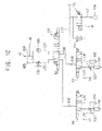
- FIG. 2 is a pneumatic circuit diagram illustrating a pneumatic control device of the auto door in FIG. 1 .
- FIG. 3 is a block diagram illustrating the pneumatic control device in FIG. 2 .
- a machine tool 10 may include a door 30 installed slidably in a side of a cover body 20 and a pneumatic control device configured to automatically open the door 30.
- the machine tool 10 may include a machine tool main body such as turning center, machining center, etc. within the cover body 20.
- the door 30, for example, may be installed to be movable along a guide rail.
- a pair of the doors 30 may be arranged to face each other. It may be understood that the number of the doors may not be limited thereto. Operations and control methods of the doors may be similar to each other, and thus, a method of controlling one door will be explained.
- the door 30 may be connected to an operation rod 42 of a door cylinder 40, and the door 30 may perform an opening and closing operations by a reciprocating motion of the operation rod 42 of the door cylinder 40.
- the door cylinder 40 may include a rod side chamber 40A and a head side chamber 40B.
- the operation rod 42 may move back, and as the compressed air is supplied to the head side chamber 40B, the operation rod 42 may move forth.
- the door 30 may be opened, and when the operation rod 42 moves forth, the door 30 may be closed.
- the pneumatic control device may include a pneumatic source 100 for generating pneumatic pressure, a first directional control valve 120 for controlling a direction of the compressed air supplied to the door cylinder 40, a door detection sensor 44A, 44B for detecting an open/close state of the door 30, first and second exhaust lines L31, L32 respectively connected to first and second outlet ports TA, TB of the first directional control valve 120, and second directional control valves 140, 142 installed in the first and second exhaust lines L31, L32 respectively.
- a pneumatic source 100 for generating pneumatic pressure
- a first directional control valve 120 for controlling a direction of the compressed air supplied to the door cylinder 40
- a door detection sensor 44A, 44B for detecting an open/close state of the door 30
- first and second exhaust lines L31, L32 respectively connected to first and second outlet ports TA, TB of the first directional control valve 120
- second directional control valves 140, 142 installed in the first and second exhaust lines L31, L32 respectively.
- the pneumatic control valve may further include a first line L41, L51 and a second line L42, L52 respectively connected to first and second working ports A, B of each of the second directional control valves 140, 142, and a deceleration valve 150, 152 installed in any one of the first and second lines.
- the pneumatic control valve may further include an emergency stop selection portion 50 for generating an emergency stop signal, an operation initiating selection portion 60 for generating an operation initiating signal which restarts an operation of the door 30 after the emergency stop signal, and a controller 200 for controlling the first direction control valve 120 and the second directional control valves 140, 142.
- the pneumatic source 100 such as a compressor may generate the compressed air.
- the pneumatic source 100 may be connected to the first directional control valve 120 through a main supply line L1 and a first supply line L11.
- a filter, a pressure adjusting valve, etc. may be installed in the main supply line L1 connected to the pneumatic source 100.
- the pneumatic control device may further include an opening/closing valve 110 installed in the main supply line L1, which connects the pneumatic source 100 and the first directional control valve 120, to open and close the main supply line L1. Additionally, the pneumatic control device may further include a flow control valve in a bypass line LP which bypasses the opening/closing valve 110.
- the opening/closing valve 110 may include a solenoid valve.
- the opening/closing valve 110 may be controlled by ON/OFF control signal A1.
- the opening/closing valve 110 may be a normally closed valve. Accordingly, when the control signal A1 is applied to the opening/closing valve 110, the opening/closing valve 110 may be switched to an open position.
- the flow control valve may include an orifice. Accordingly, an amount of the compressed air passing though the bypass line LP may be reduced.
- the opening/closing valve 110 may be in a closed position, and a relatively small amount of the compressed air from the pneumatic source 110 may be supplied through the bypass line LP.
- the first directional control valve 120 may be connected to the door cylinder 40 through a rod side line L21 and a head side line L22.
- the rod side line L21 may be connected to the rod side chamber 40A of the door cylinder 40 and the head side line L22 may be connected to the head side chamber 40B of the door cylinder 40.
- flow control valves 130, 132 may be installed in the rod side line L21 and the head side line L22 respectively.
- the first directional control valve may include 5 port 3 position direction control valve.
- the first directional control valve may include a pilot operated solenoid control valve.
- the rod side line L21 may be connected to a first working port A of the first directional control valve 120 and the head side line L22 may be connected to the second working port B of the first directional control valve 120.
- the first directional control valve 120 When a door opening control signal A2 is applied to the first directional control valve 120, the first directional control valve 120 may be switched to a first position (door open position) 120A. When a door closing control signal B2 is applied to the first directional control valve 120, the first directional control valve 120 may be switched to a second position (door closed position) 120B. When a door neutral control signal is applied to the first directional control valve 120, the first directional control valve 120 may be switched to a third position (door neutral position) 120C.
- the compressed air which drives the door cylinder 40 may be exhausted through the second directional control valves 140, 142 installed in the first and second exhaust lines L31, L32 connected to the outlet ports of the first directional control valve 120 respectively.
- the first exhaust line L31 may be connected to a first outlet port TA of the first directional control valve 120 and the second exhaust line L32 may be connected to a second outlet portion TB of the first directional control valve 120.
- the second directional control valve 140 may be installed in the first exhaust line L31, and the second directional control valve 142 may be installed in the second exhaust line L32.
- the second directional control valves 140, 142 may include 2 position direction control valve.
- the second directional control valves 140, 142 may be a pilot operated solenoid control valve.
- the second directional control valves 140, 142 may be a normally open valve.
- the first line L41 may be connected to the first working port A of the second directional control valve 140 and the second line L42 may be connected to the second working port B of the second directional control valve 140.
- the deceleration valve 150 may be installed in the second line L42 to reduce speed of the compressed air exhausted through the second line L42.
- the first line L51 may be connected to the first working port A of the second directional control valve 142 and the second line L52 may be connected to the second working port B of the second directional control valve 142.
- the deceleration valve 152 may be installed in the second line L52 to reduce speed of the compressed air exhausted through the second line L42.
- a sound absorber 160 may be installed in each of the first line L41, L51 and the second line L42, L52.
- the deceleration valves 150, 152 may include a flow control valve.
- the deceleration valves 150, 152 may include a variable orifice.
- the second directional control valves 140, 142 When a control signal A3, A4 is not applied, the second directional control valves 140, 142 may be in a first position 140A, 142A, and the compressed air may be exhausted at a first speed through the second directional control valve 140, 142.
- the control signal A3, A4 is applied to the second directional opening/closing valve 110, the second directional control valves 140, 142 may be switched to a second position 140B, 142B, and the compressed air may be exhausted at a second speed less than the first speed through the second directional control valves 140, 142.
- a controller 20 may be electrically connected to the emergency stop selection portion 50, the operation initiation selection portion 60 and the door detection sensor 44A, 44B to receive signals therefrom, and may output control signals A1, A2, B2 A3, A4 to the opening/closing valve 110, the first directional control valve 120 and the second directional control valves 140, 142.
- the controller 20 may output electrical control signals A1, A2, B2, A3, A4 for opening the door 30 according to a workpiece machining program (CNC program).
- CNC program workpiece machining program
- the emergency stop selection portion 50 may include a push button which an operator presses at emergency. When the operator presses the push button, an emergency stop signal E may be generated to be outputted to the controller 200. Alternatively, the emergency stop selection portion 50 may output the emergency stop signal generated by control logic to the controller 200.
- the operation initiating selection portion 60 may include a push button which generates an operation signal R for restarting the operation of the door 30 after the emergency stop signal.
- the operation signal R for restarting may be outputted to the controller 200.
- the door detection sensor 44A, 44B may include limit switches installed in the cover body 20 to detect whether or not the door 30 is opened, proximity sensors installed in the door cylinder 40, etc.
- the first door detection sensor 44A may detect a completely closed state of the door 30 and the detected signal S1 may be outputted to the controller 200.
- the second detection sensor 44B may detect a completely open state of the door 30 and the detected signal S2 may be outputted to the controller 200.
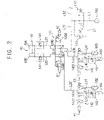
- FIG. 4 is a pneumatic circuit diagram illustrating a step of opening the door in the pneumatic control device of FIG. 2 .
- FIG. 5 is graphs illustrating signals inputted/outputted to/from the controller in the step of FIG. 4 .
- the controller 200 may output the door opening control signal A2 to the first directional control valve 120 and output the ON/OFF control signal A1 to the opening/closing valve 110 for opening the door 30.
- the first directional control valve 120 may be switched to the first position (door open position) and the opening/closing valve 110 may be switched to the open position.
- the compressed air from the pneumatic source 100 may be supplied to the rod side chamber 40A of the door cylinder 40 through the rod side line L21 via the opening/closing valve 110 and the first directional control valve 120, so that the operation rod 42 may move back and the door 30 may be opened.
- the compressed air within the head side chamber 40B may be exhausted through the head side line L22 via the first directional control valve 120 and the second control valve 142.
- the compressed air passing through the second exhaust line L32 connected to the second outlet port TB of the first directional control valve 120 may be exhausted to the surrounding atmosphere through the first line L51 connected to the first working port A of the second directional control valve 142.
- the controller 200 may count a door opening operation time, and may output the control signal for reducing the exhaust speed of the compressed air by lapse of a predetermined time (deceleration timer section) after outputting the door opening control signal A2.
- the controller 200 may stop output of the ON/OFF control signal A1 at time close to end point of the door opening operation and may output the control signal A4 to the second directional control valve 142.
- the opening/closing valve 110 may be switched to the closed position, and the second directional control valve 142 may be switched to the second position.
- the amount (speed) of the compressed air supplied to the door cylinder 40 may be reduced. Further, because the compressed air exhausted through the second directional control valve 142 is exhausted via the deceleration valve 152 installed in the second line L52, the amount (speed) of the exhausted compressed air may be reduced. Thus, the speed of the door 30 at the end point of the door opening operation may be reduced to thereby prevent impact due to opening of the door 30 and resultant noises.
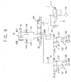
- FIG. 6 is a pneumatic circuit diagram illustrating a step of closing the door in the pneumatic control device of FIG. 2 .
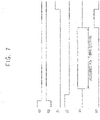
- FIG. 7 is graphs illustrating signals inputted/outputted to/from the controller in the step of FIG. 6 .
- the controller 200 may output the door closing control signal B2 to the first directional control valve 120 and output the ON/OFF control signal A1 to the opening/closing valve 110 for closing the door 30.
- the first directional control valve 120 may be switched to the second position (door closed position) and the opening/closing valve 110 may be switched to the open position.
- the compressed air from the pneumatic source 100 may be supplied to the head side chamber 40B of the door cylinder 40 through the head side line L22 via the opening/closing valve 110 and the first directional control valve 120, so that the operation rod 42 may move forth and the door 30 may be closed.
- the compressed air within the rod side chamber 40A may be exhausted through the rod side line L21 via the first directional control valve 120 and the second control valve 140.
- the compressed air passing through the first exhaust line L31 connected to the first outlet port TA of the first directional control valve 120 may be exhausted to the surrounding atmosphere through the first line L41 connected to the first working port A of the second directional control valve 140.
- the controller 200 may count a door closing operation time, and may output the control signal for reducing the exhaust speed of the compressed air by lapse of a predetermined time (deceleration timer section) after outputting the door closing control signal B2.
- the controller 200 may stop output of the ON/OFF control signal A1 at time close to end point of the door closing operation and may output the control signal A3 to the second directional control valve 140.
- the opening/closing valve 110 may be switched to the closed position, and the second directional control valve 140 may be switched to the second position.
- the amount (speed) of the compressed air supplied to the door cylinder 40 may be reduced. Further, because the compressed air exhausted through the second directional control valve 140 is exhausted via the deceleration valve 150 installed in the second line L42, the amount (speed) of the exhausted compressed air may be reduced. Thus, the speed of the door 30 at the end point of the door closing operation may be reduced to thereby prevent impact due to closing of the door 30 and resultant noises.
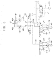
- FIG. 8 is a pneumatic circuit diagram illustrating a step of an emergency stop operation in the pneumatic control device of FIG. 2 .
- FIG. 9 is graphs illustrating signals inputted/outputted to/from the controller in the step of FIG. 8 .
- the controller 200 may receive the emergency stop signal E, stop output of the door opening/closing control signals A2, B2 and stop output of the ON/OFF control signal A1 for stop the operation of the door 30.
- the first directional control valve 120 may be switched to the third position (door neutral position) and the opening/closing valve 110 may be switched to the closed position.
- the supply of compressed air from the pneumatic source 100 may be stopped, the compressed air within the rod side chamber 40A may be exhausted through the rod side line L21 via the first directional control valve 120 and the second control valve 140, and the compressed air within the head side chamber 40B may be exhausted through the head side line L22 via the first directional control valve 120 and the second control valve 142.
- the compressed air passing through the first exhaust line L31 connected to the first outlet port TA of the first directional control valve 120 may be exhausted to the surrounding atmosphere through the first line L41 connected to the first working port A of the second directional control valve 140, and the compressed air passing through the second exhaust line L32 connected to the second outlet port TB of the first directional control valve 120 may be exhausted to the surrounding atmosphere through the first line L51 connected to the first working port A of the second directional control valve 142 .
- the compressed air within the rod side chamber 40A and the head side chamber 40B of the door cylinder 40 may be exhausted rapidly through the first directional control valve 120 and the second directional control valves 140, 142 to thereby rapidly stop the operation of the door 30.
- FIG. 10 is a pneumatic circuit diagram illustrating a step of restarting the operation of the door after the emergency stop operation in the pneumatic control device of FIG. 2 .
- FIG. 11 is graphs illustrating signals inputted/outputted to/from the controller in the step of FIG. 10 .
- the controller 200 may receive the operation signal R for restarting the operation of the door 30 after the emergency stop signal E, and, at the beginning, stop output of the ON/OFF control signal A1 and output the control signal A3, A4 to the second directional control valves 140, 142 for restarting the operation of the door 30.
- the controller 200 may not receive the door opening/closing control signals S1, S2 from the first and second door detection sensors 44A, 44B. Additionally, the controller 200 may output the door control signal A2, B2 to the first directional control valve 120 for switching the first directional control valve 120 to the switched position before the emergency stop signal E.
- the first directional control valve 120 may be switched to the second position (door closed position) according to the operation signal R. Additionally, the opening/closing valve 110 may be switched to the closed position, and the second directional control valves 140, 142 may be switched to the second position respectively.
- the compressed air from the pneumatic source 110 is supplied through the bypass line LP via the orifice, the amount (speed) of the compressed air supplied to the door cylinder 40 may be reduced. Further, because the compressed air exhausted through the second directional control valve 140 is exhausted via the deceleration valve 150 installed in the second line L42, the amount (speed) of the exhausted compressed air may be reduced. Thus, when a system is restarted after the emergency stop, sudden acceleration of the door 30 may be prevented.
- FIG. 12 is a pneumatic circuit diagram illustrating a control method in case that the door is completely open or closed when restarting the operation of the door after the emergency stop operation in the pneumatic control device of FIG. 2 .
- FIG. 13 is graphs illustrating signals inputted/outputted to/from the controller in the step of FIG. 12 .
- the controller 200 may receive the operation signal R for restarting the operation of the door 30 after the emergency stop signal E, and, at the beginning, stop output of the ON/OFF control signal A1 for restarting the operation of the door 30.
- the controller 200 may receive the door opening/closing control signals S1, S2 from the first and second door detection sensors 44A, 44B, and may not output the control signal A3, A4 to the second directional control valves 140, 142. Additionally, the controller 200 may output the door control signal A2, B2 to the first directional control valve 120 for switching the first directional control valve 120 to the switched position before the emergency stop signal E.
- the first directional control valve 120 may be switched to the first position (door open position) according to the operation signal R. Additionally, the opening/closing valve 110 may be switched to the closed position. But, because the door 30 is completely closed, the second directional control valves 140, 142 may not be switched to the second position and may be maintained the first position. Accordingly, the exhaust speed of the compressed air exhausted from the second directional control valves 140, 142 may be maintained at a relatively rapid speed.
- the compressed air within the door cylinder 40 may be exhausted through the second directional valves 140, 142 according to the emergency stop signal E, when the operation signal E is generated after the emergency stop signal, in case that the door 30 is not completely closed, the second directional control valve 140, 142 may be switched to reduce the exhaust speed of the compressed air. Accordingly, when the system is restarted after the emergency stop, the sudden acceleration of the door 30 may be prevented.
Landscapes
- Engineering & Computer Science (AREA)
- Mechanical Engineering (AREA)
- Physics & Mathematics (AREA)
- Fluid Mechanics (AREA)
- General Engineering & Computer Science (AREA)
- Business, Economics & Management (AREA)
- Emergency Management (AREA)
- Chemical & Material Sciences (AREA)
- Analytical Chemistry (AREA)
- Fluid-Pressure Circuits (AREA)
- Power-Operated Mechanisms For Wings (AREA)
Description
- The present invention relates to a pneumatic control device and a pneumatic control method of auto door. More particularly, the present invention relates to a pneumatic control device to automatically a door of a machine tool and a pneumatic control method using the same.
- Generally, workpieces and tools may be carried into or taken out of a machine tool through a door. In a pneumatic circuit diagram of auto door for automatically opening and closing the door, an amount of a compressed air supplied to a door cylinder for opening and closing the door from a pneumatic source may be adjusted. However, when a normal operation restarts right after an emergency stop, sudden acceleration of the door may be generated thereby deteriorating controllability. Patent Literature
KR 2015 0102772 A KR 101 000 899 B1 KR 2013 0085684 A - An object of the present invention provides a pneumatic control device of auto door capable of preventing sudden acceleration after an emergency stop.
- Another object of the present invention provides a pneumatic control method of controlling an auto door using the pneumatic control device.
- According to the present invention, a pneumatic control device of auto door includes a first directional control valve configured to control a direction of a compressed air supplied to a door cylinder for opening and closing a door, a door detection sensor configured to detect an open/close state of the door, first and second exhaust lines respectively connected to first and second outlet ports of the first directional control valve, and second directional control valves installed in the first and second exhaust lines respectively to operably exhaust the compressed air exhausted from the first and second outlet ports according to an emergency stop signal, and capable of changing positions to reduce an exhaust speed of the compressed air, and a controller configured to receive signals from the door detection sensor and output control signals to the first directional control valve and the second directional control valves respectively to control operations thereof. The controller outputs the control signal for opening and closing the door to the first directional control valve to supply the compressed air to the door cylinder through the first directional control valve. The controller outputs the control signal for stopping the operation of the door to the first directional control valve to stop the supply of the compressed air and outputs the control signal for exhausting the compressed air to the second directional control valves to exhaust the compressed air from the first and second outlet ports through the second directional control valves according to the emergency stop signal. The controller switches the second directional control valves to reduce the exhaust speed of the compressed air in case that the door is not completely open or closed when an operation signal is generated after the emergency stop signal.
- In example embodiments, the pneumatic control device of auto door may further include first and second lines respectively connected to first and second working ports of the second directional control valve, and a deceleration valve installed in any one of the first and second lines.
- In example embodiments, the deceleration valve may include a variable orifice.
- In example embodiments, each of the second directional control valves may be operable to maintain the exhaust speed of the compressed air in case that the door is completely open or closed when the operation signal is generated after the emergency stop signal.
- In example embodiments, the pneumatic control device of auto door may further include an emergency stop selection portion for generating and outputting the emergency stop signal to the controller, and an operation initiating selection portion for generating an operation signal which restarts an operation of the door after the emergency stop signal to the controller.
- In example embodiments, when the controller receives the emergency stop signal, the controller may control that the first directional control valve is switched to be a neutral position.
- In example embodiments, when the controller receives the operation signal, the controller may output the control signal before the emergency stop signal to the first directional control valve.
- In example embodiments, the controller may output the control signal for reducing the exhaust speed of the compressed air to the second directional control valve by lapse of a predetermined time after outputting the control signal for opening and closing the door to the first directional control valve.
- In example embodiments, the pneumatic control device of auto door may further include an opening/closing valve installed in a supply line which connects a pneumatic source and the first directional control valve to open and close the supply line.
- In example embodiments, the pneumatic control device may further include an orifice installed valve in a bypass line which bypasses the opening/closing valve.
- In example embodiments, the first and second directional control valves may include a pilot operated solenoid control valve.
- In example embodiments, the first directional control valve may include 5 port 3 position direction control valve.
- According to example embodiments, in a pneumatic control method of auto door, second directional control valves are installed respectively in first and second exhaust lines respectively connected to first and second outlet ports of a first directional control valve. A compressed air is supplied to a door cylinder through the first directional control valve. An open/close state of the door is detected. The compressed air is exhausted from the first and second outlet ports through the second directional control valves according to an emergency stop signal. The second directional control valve is switched to reduce an exhaust speed of the compressed air in case that the door is not completely open or closed when an operation signal is generated after the emergency stop signal.
- In example embodiments, the pneumatic control method may further include making no changes in positions of the second directional control valve to maintain the exhaust speed of the compressed air in case that the door is completely open or closed when the operation signal is generated after the emergency stop signal.
- In example embodiments, the pneumatic control method may further switching the first directional control valve to a switched position before the emergency stop signal.
- According to example embodiments, a pneumatic control device of auto door, includes a first directional control valve configured to control a direction of a compressed air supplied to a door cylinder for opening and closing a door, and second directional control valves installed in first and second exhaust lines respectively connected to first and second outlet ports of the first directional control valve.
- The compressed air may be exhausted from the first and second outlet ports through the second directional control valves according to an emergency stop signal, and in case that the door is not completely open or closed when an operation signal is generated after the emergency stop signal, the second directional control valve is switched to reduce an exhaust speed of the compressed air.
- Accordingly, when a system is restarted after the emergency stop, sudden acceleration of the door may be prevented.
- However, the effect of the invention may not be limited thereto, and may be expanded without being deviated from the concept and the scope of the present invention.
-
-
FIG. 1 is a perspective view illustrating a machine tool having an auto door in accordance with example embodiments. -
FIG. 2 is a pneumatic circuit diagram illustrating a pneumatic control device of the auto door inFIG. 1 . -
FIG. 3 is a block diagram illustrating the pneumatic control device inFIG. 2 . -
FIG. 4 is a pneumatic circuit diagram illustrating a step of opening the door in the pneumatic control device ofFIG. 2 . -
FIG. 5 is graphs illustrating signals inputted/outputted to/from the controller in the step ofFIG. 4 . -
FIG. 6 is a pneumatic circuit diagram illustrating a step of closing the door in the pneumatic control device ofFIG. 2 . -
FIG. 7 is graphs illustrating signals inputted/outputted to/from the controller in the step ofFIG. 6 . -
FIG. 8 is a pneumatic circuit diagram illustrating a step of an emergency stop operation in the pneumatic control device ofFIG. 2 . -
FIG. 9 is graphs illustrating signals inputted/outputted to/from the controller in the step ofFIG. 8 . -
FIG. 10 is a pneumatic circuit diagram illustrating a step of restarting the operation of the door after the emergency stop operation in the pneumatic control device ofFIG. 2 . -
FIG. 11 is graphs illustrating signals inputted/outputted to/from the controller in the step ofFIG. 10 . -
FIG. 12 is a pneumatic circuit diagram illustrating a control method in case that the door is completely open or closed when restarting the operation of the door after the emergency stop operation in the pneumatic control device ofFIG. 2 . -
FIG. 13 is graphs illustrating signals inputted/outputted to/from the controller in the step ofFIG. 12 . - Hereinafter, preferable embodiments of the present invention will be explained in detail with reference to the accompanying drawings.
- In the drawings, the sizes and relative sizes of components or elements may be exaggerated for clarity.
- It will be understood that, although the terms first, second, third, etc. may be used herein to describe various elements, components, regions, layers and/or sections, these elements, components, regions, layers and/or sections should not be limited by these terms. These terms are only used to distinguish one element, component, region, layer or section from another element, component, region, layer or section. Thus, a first element, component, region, layer or section discussed below could be termed a second element, component, region, layer or section without departing from the teachings of example embodiments.
- The terminology used herein is for the purpose of describing particular example embodiments only and is not intended to be limiting of example embodiments. As used herein, the singular forms "a," "an" and "the" are intended to include the plural forms as well, unless the context clearly indicates otherwise. It will be further understood that the terms "comprises" and/or "comprising," when used in this specification, specify the presence of stated features, integers, steps, operations, elements, and/or components, but do not preclude the presence or addition of one or more other features, integers, steps, operations, elements, components, and/or groups thereof.
- Unless otherwise defined, all terms (including technical and scientific terms) used herein have the same meaning as commonly understood by one of ordinary skill in the art to which example embodiments belong. It will be further understood that terms, such as those defined in commonly used dictionaries, should be interpreted as having a meaning that is consistent with their meaning in the context of the relevant art and will not be interpreted in an idealized or overly formal sense unless expressly so defined herein.
- Example embodiments may, however, be embodied in many different forms and should not be construed as limited to example embodiments set forth herein. Rather, these example embodiments are provided so that this disclosure will be thorough and complete, and will fully convey the scope of example embodiments to those skilled in the art.
-
FIG. 1 is a perspective view illustrating a machine tool having an auto door in accordance with example embodiments.FIG. 2 is a pneumatic circuit diagram illustrating a pneumatic control device of the auto door inFIG. 1 .FIG. 3 is a block diagram illustrating the pneumatic control device inFIG. 2 . - Referring to
FIGS. 1 to 3 , amachine tool 10 may include adoor 30 installed slidably in a side of acover body 20 and a pneumatic control device configured to automatically open thedoor 30. - In example embodiments, the
machine tool 10 may include a machine tool main body such as turning center, machining center, etc. within thecover body 20. Thedoor 30, for example, may be installed to be movable along a guide rail. A pair of thedoors 30 may be arranged to face each other. It may be understood that the number of the doors may not be limited thereto. Operations and control methods of the doors may be similar to each other, and thus, a method of controlling one door will be explained. - The
door 30 may be connected to anoperation rod 42 of adoor cylinder 40, and thedoor 30 may perform an opening and closing operations by a reciprocating motion of theoperation rod 42 of thedoor cylinder 40. Thedoor cylinder 40 may include arod side chamber 40A and ahead side chamber 40B. For example, as a compressed air is supplied to therod side chamber 40A, theoperation rod 42 may move back, and as the compressed air is supplied to thehead side chamber 40B, theoperation rod 42 may move forth. When theoperation rod 42 moves back, thedoor 30 may be opened, and when theoperation rod 42 moves forth, thedoor 30 may be closed. - The pneumatic control device may include a
pneumatic source 100 for generating pneumatic pressure, a firstdirectional control valve 120 for controlling a direction of the compressed air supplied to thedoor cylinder 40, adoor detection sensor door 30, first and second exhaust lines L31, L32 respectively connected to first and second outlet ports TA, TB of the firstdirectional control valve 120, and seconddirectional control valves - In addition, the pneumatic control valve may further include a first line L41, L51 and a second line L42, L52 respectively connected to first and second working ports A, B of each of the second
directional control valves deceleration valve - Further, the pneumatic control valve may further include an emergency
stop selection portion 50 for generating an emergency stop signal, an operation initiatingselection portion 60 for generating an operation initiating signal which restarts an operation of thedoor 30 after the emergency stop signal, and acontroller 200 for controlling the firstdirection control valve 120 and the seconddirectional control valves - The
pneumatic source 100 such as a compressor may generate the compressed air. Thepneumatic source 100 may be connected to the firstdirectional control valve 120 through a main supply line L1 and a first supply line L11. Although it is not illustrated in the drawings, a filter, a pressure adjusting valve, etc. may be installed in the main supply line L1 connected to thepneumatic source 100. - In example embodiments, the pneumatic control device may further include an opening/
closing valve 110 installed in the main supply line L1, which connects thepneumatic source 100 and the firstdirectional control valve 120, to open and close the main supply line L1. Additionally, the pneumatic control device may further include a flow control valve in a bypass line LP which bypasses the opening/closing valve 110. - For example, the opening/
closing valve 110 may include a solenoid valve. The opening/closing valve 110 may be controlled by ON/OFF control signal A1. The opening/closing valve 110 may be a normally closed valve. Accordingly, when the control signal A1 is applied to the opening/closing valve 110, the opening/closing valve 110 may be switched to an open position. - Additionally, the flow control valve may include an orifice. Accordingly, an amount of the compressed air passing though the bypass line LP may be reduced. When the control signal A1 is not applied, the opening/
closing valve 110 may be in a closed position, and a relatively small amount of the compressed air from thepneumatic source 110 may be supplied through the bypass line LP. - The first
directional control valve 120 may be connected to thedoor cylinder 40 through a rod side line L21 and a head side line L22. The rod side line L21 may be connected to therod side chamber 40A of thedoor cylinder 40 and the head side line L22 may be connected to thehead side chamber 40B of thedoor cylinder 40. Additionally, flowcontrol valves - For example, the first directional control valve may include 5 port 3 position direction control valve. The first directional control valve may include a pilot operated solenoid control valve. The rod side line L21 may be connected to a first working port A of the first
directional control valve 120 and the head side line L22 may be connected to the second working port B of the firstdirectional control valve 120. - When a door opening control signal A2 is applied to the first
directional control valve 120, the firstdirectional control valve 120 may be switched to a first position (door open position) 120A. When a door closing control signal B2 is applied to the firstdirectional control valve 120, the firstdirectional control valve 120 may be switched to a second position (door closed position) 120B. When a door neutral control signal is applied to the firstdirectional control valve 120, the firstdirectional control valve 120 may be switched to a third position (door neutral position) 120C. - The compressed air which drives the
door cylinder 40 may be exhausted through the seconddirectional control valves directional control valve 120 respectively. - The first exhaust line L31 may be connected to a first outlet port TA of the first
directional control valve 120 and the second exhaust line L32 may be connected to a second outlet portion TB of the firstdirectional control valve 120. The seconddirectional control valve 140 may be installed in the first exhaust line L31, and the seconddirectional control valve 142 may be installed in the second exhaust line L32. - For example, the second
directional control valves directional control valves directional control valves - In example embodiments, the first line L41 may be connected to the first working port A of the second
directional control valve 140 and the second line L42 may be connected to the second working port B of the seconddirectional control valve 140. Thedeceleration valve 150 may be installed in the second line L42 to reduce speed of the compressed air exhausted through the second line L42. Additionally, the first line L51 may be connected to the first working port A of the seconddirectional control valve 142 and the second line L52 may be connected to the second working port B of the seconddirectional control valve 142. Thedeceleration valve 152 may be installed in the second line L52 to reduce speed of the compressed air exhausted through the second line L42. Further, asound absorber 160 may be installed in each of the first line L41, L51 and the second line L42, L52. - For example, the
deceleration valves deceleration valves - When a control signal A3, A4 is not applied, the second
directional control valves first position directional control valve closing valve 110, the seconddirectional control valves second position directional control valves - As illustrated in
FIG. 3 , acontroller 20 may be electrically connected to the emergencystop selection portion 50, the operationinitiation selection portion 60 and thedoor detection sensor closing valve 110, the firstdirectional control valve 120 and the seconddirectional control valves controller 20 may output electrical control signals A1, A2, B2, A3, A4 for opening thedoor 30 according to a workpiece machining program (CNC program). - The emergency
stop selection portion 50 may include a push button which an operator presses at emergency. When the operator presses the push button, an emergency stop signal E may be generated to be outputted to thecontroller 200. Alternatively, the emergencystop selection portion 50 may output the emergency stop signal generated by control logic to thecontroller 200. - The operation initiating
selection portion 60 may include a push button which generates an operation signal R for restarting the operation of thedoor 30 after the emergency stop signal. When the operation initiatingselection portion 60 is selected, the operation signal R for restarting may be outputted to thecontroller 200. - The
door detection sensor cover body 20 to detect whether or not thedoor 30 is opened, proximity sensors installed in thedoor cylinder 40, etc. For example, the firstdoor detection sensor 44A may detect a completely closed state of thedoor 30 and the detected signal S1 may be outputted to thecontroller 200. Thesecond detection sensor 44B may detect a completely open state of thedoor 30 and the detected signal S2 may be outputted to thecontroller 200. - Hereinafter, a method of controlling a door using the pneumatic control device in
FIG. 2 will be explained. -
FIG. 4 is a pneumatic circuit diagram illustrating a step of opening the door in the pneumatic control device ofFIG. 2 .FIG. 5 is graphs illustrating signals inputted/outputted to/from the controller in the step ofFIG. 4 . - Referring to
FIGS. 3 ,4 and5 , thecontroller 200 may output the door opening control signal A2 to the firstdirectional control valve 120 and output the ON/OFF control signal A1 to the opening/closing valve 110 for opening thedoor 30. - Thus, the first
directional control valve 120 may be switched to the first position (door open position) and the opening/closing valve 110 may be switched to the open position. The compressed air from thepneumatic source 100 may be supplied to therod side chamber 40A of thedoor cylinder 40 through the rod side line L21 via the opening/closing valve 110 and the firstdirectional control valve 120, so that theoperation rod 42 may move back and thedoor 30 may be opened. The compressed air within thehead side chamber 40B may be exhausted through the head side line L22 via the firstdirectional control valve 120 and thesecond control valve 142. In particular, the compressed air passing through the second exhaust line L32 connected to the second outlet port TB of the firstdirectional control valve 120 may be exhausted to the surrounding atmosphere through the first line L51 connected to the first working port A of the seconddirectional control valve 142. - In here, the
controller 200 may count a door opening operation time, and may output the control signal for reducing the exhaust speed of the compressed air by lapse of a predetermined time (deceleration timer section) after outputting the door opening control signal A2. - In particular, the
controller 200 may stop output of the ON/OFF control signal A1 at time close to end point of the door opening operation and may output the control signal A4 to the seconddirectional control valve 142. Thus, the opening/closing valve 110 may be switched to the closed position, and the seconddirectional control valve 142 may be switched to the second position. - Accordingly, because the compressed air from the
pneumatic source 110 is supplied through the bypass line LP via the orifice, the amount (speed) of the compressed air supplied to thedoor cylinder 40 may be reduced. Further, because the compressed air exhausted through the seconddirectional control valve 142 is exhausted via thedeceleration valve 152 installed in the second line L52, the amount (speed) of the exhausted compressed air may be reduced. Thus, the speed of thedoor 30 at the end point of the door opening operation may be reduced to thereby prevent impact due to opening of thedoor 30 and resultant noises. -
FIG. 6 is a pneumatic circuit diagram illustrating a step of closing the door in the pneumatic control device ofFIG. 2 .FIG. 7 is graphs illustrating signals inputted/outputted to/from the controller in the step ofFIG. 6 . - Referring to
FIGS. 3 ,6 and7 , thecontroller 200 may output the door closing control signal B2 to the firstdirectional control valve 120 and output the ON/OFF control signal A1 to the opening/closing valve 110 for closing thedoor 30. - Thus, the first
directional control valve 120 may be switched to the second position (door closed position) and the opening/closing valve 110 may be switched to the open position. The compressed air from thepneumatic source 100 may be supplied to thehead side chamber 40B of thedoor cylinder 40 through the head side line L22 via the opening/closing valve 110 and the firstdirectional control valve 120, so that theoperation rod 42 may move forth and thedoor 30 may be closed. The compressed air within therod side chamber 40A may be exhausted through the rod side line L21 via the firstdirectional control valve 120 and thesecond control valve 140. In particular, the compressed air passing through the first exhaust line L31 connected to the first outlet port TA of the firstdirectional control valve 120 may be exhausted to the surrounding atmosphere through the first line L41 connected to the first working port A of the seconddirectional control valve 140. - In here, the
controller 200 may count a door closing operation time, and may output the control signal for reducing the exhaust speed of the compressed air by lapse of a predetermined time (deceleration timer section) after outputting the door closing control signal B2. - In particular, the
controller 200 may stop output of the ON/OFF control signal A1 at time close to end point of the door closing operation and may output the control signal A3 to the seconddirectional control valve 140. Thus, the opening/closing valve 110 may be switched to the closed position, and the seconddirectional control valve 140 may be switched to the second position. - Accordingly, because the compressed air from the
pneumatic source 110 is supplied through the bypass line LP via the orifice, the amount (speed) of the compressed air supplied to thedoor cylinder 40 may be reduced. Further, because the compressed air exhausted through the seconddirectional control valve 140 is exhausted via thedeceleration valve 150 installed in the second line L42, the amount (speed) of the exhausted compressed air may be reduced. Thus, the speed of thedoor 30 at the end point of the door closing operation may be reduced to thereby prevent impact due to closing of thedoor 30 and resultant noises. -
FIG. 8 is a pneumatic circuit diagram illustrating a step of an emergency stop operation in the pneumatic control device ofFIG. 2 .FIG. 9 is graphs illustrating signals inputted/outputted to/from the controller in the step ofFIG. 8 . - Referring to
FIGS. 3 ,8 and9 , thecontroller 200 may receive the emergency stop signal E, stop output of the door opening/closing control signals A2, B2 and stop output of the ON/OFF control signal A1 for stop the operation of thedoor 30. - Thus, the first
directional control valve 120 may be switched to the third position (door neutral position) and the opening/closing valve 110 may be switched to the closed position. The supply of compressed air from thepneumatic source 100 may be stopped, the compressed air within therod side chamber 40A may be exhausted through the rod side line L21 via the firstdirectional control valve 120 and thesecond control valve 140, and the compressed air within thehead side chamber 40B may be exhausted through the head side line L22 via the firstdirectional control valve 120 and thesecond control valve 142. In particular, the compressed air passing through the first exhaust line L31 connected to the first outlet port TA of the firstdirectional control valve 120 may be exhausted to the surrounding atmosphere through the first line L41 connected to the first working port A of the seconddirectional control valve 140, and the compressed air passing through the second exhaust line L32 connected to the second outlet port TB of the firstdirectional control valve 120 may be exhausted to the surrounding atmosphere through the first line L51 connected to the first working port A of the seconddirectional control valve 142 . - Thus, the compressed air within the
rod side chamber 40A and thehead side chamber 40B of thedoor cylinder 40 may be exhausted rapidly through the firstdirectional control valve 120 and the seconddirectional control valves door 30. -
FIG. 10 is a pneumatic circuit diagram illustrating a step of restarting the operation of the door after the emergency stop operation in the pneumatic control device ofFIG. 2 .FIG. 11 is graphs illustrating signals inputted/outputted to/from the controller in the step ofFIG. 10 . - Referring to
FIGS. 3 ,10 and11 , thecontroller 200 may receive the operation signal R for restarting the operation of thedoor 30 after the emergency stop signal E, and, at the beginning, stop output of the ON/OFF control signal A1 and output the control signal A3, A4 to the seconddirectional control valves door 30. In here, in case that thedoor 30 is not completely open or closed, thecontroller 200 may not receive the door opening/closing control signals S1, S2 from the first and seconddoor detection sensors controller 200 may output the door control signal A2, B2 to the firstdirectional control valve 120 for switching the firstdirectional control valve 120 to the switched position before the emergency stop signal E. - For example, in case the emergency stop signal E is generated in the step of closing the door, the first
directional control valve 120 may be switched to the second position (door closed position) according to the operation signal R. Additionally, the opening/closing valve 110 may be switched to the closed position, and the seconddirectional control valves - Accordingly, because the compressed air from the
pneumatic source 110 is supplied through the bypass line LP via the orifice, the amount (speed) of the compressed air supplied to thedoor cylinder 40 may be reduced. Further, because the compressed air exhausted through the seconddirectional control valve 140 is exhausted via thedeceleration valve 150 installed in the second line L42, the amount (speed) of the exhausted compressed air may be reduced. Thus, when a system is restarted after the emergency stop, sudden acceleration of thedoor 30 may be prevented. -
FIG. 12 is a pneumatic circuit diagram illustrating a control method in case that the door is completely open or closed when restarting the operation of the door after the emergency stop operation in the pneumatic control device ofFIG. 2 .FIG. 13 is graphs illustrating signals inputted/outputted to/from the controller in the step ofFIG. 12 . - Referring to
FIGS. 3 ,12 and13 , thecontroller 200 may receive the operation signal R for restarting the operation of thedoor 30 after the emergency stop signal E, and, at the beginning, stop output of the ON/OFF control signal A1 for restarting the operation of thedoor 30. In here, in case that thedoor 30 is completely open or closed, thecontroller 200 may receive the door opening/closing control signals S1, S2 from the first and seconddoor detection sensors directional control valves controller 200 may output the door control signal A2, B2 to the firstdirectional control valve 120 for switching the firstdirectional control valve 120 to the switched position before the emergency stop signal E. - For example, in case the emergency stop signal E is generated in the step of opening the door, the first
directional control valve 120 may be switched to the first position (door open position) according to the operation signal R. Additionally, the opening/closing valve 110 may be switched to the closed position. But, because thedoor 30 is completely closed, the seconddirectional control valves directional control valves - As mentioned above, the compressed air within the
door cylinder 40 may be exhausted through the seconddirectional valves door 30 is not completely closed, the seconddirectional control valve door 30 may be prevented. - The present invention has been explained with reference to preferable embodiments, however, those skilled in the art may understand that the present invention may be modified or changed without being deviated from the scope of the present invention disclosed in the following claims.
-
- 10: machine tool 20: cover body
- 30: door 40: door cylinder
- 40A:
rod side chamber 40B: head side chamber - 42:
operation rod - 50: emergency stop selection portion 60: operation initiating selection portion
- 100: pneumatic source 110: opening/closing valve
- 120: first
directional control valve 130, 132: flow control valve - 140, 142: second
directional control valve 150, 152: deceleration valve - 200: controller
Claims (15)
- A pneumatic control device of auto door, comprising:a first directional control valve (120) configured to control a direction of a compressed air supplied to a door cylinder (40) for opening and closing a door (30); andfirst and second exhaust lines (L31, L32) respectively connected to first and second outlet ports (TA, TB) of the first directional control valve (120); characterized in that the device further comprisesa door detection sensor (44A, 44B) configured to detect an open/close state of the door (30);second directional control valves (140, 142) installed in the first and second exhaust lines respectively to operably exhaust the compressed air exhausted from the first and second outlet ports (TA, TB) according to an emergency stop signal, and capable of changing positions to reduce an exhaust speed of the compressed air; anda controller (200) configured to receive signals from the door detection sensor (44A, 44B) and output control signals to the first directional control valve (120) and the second directional control valves (140, 142) respectively to control operations thereof,wherein the controller (200) outputs the control signal for opening and closing the door (30) to the first directional control valve (120) to supply the compressed air to the door cylinder (40) through the first directional control valve (120),wherein the controller (200) outputs the control signal for stopping the operation of the door (30) to the first directional control valve (120) to stop the supply of the compressed air and outputs the control signal for exhausting the compressed air to the second directional control valves (140, 142) to exhaust the compressed air from the first and second outlet ports (TA, TB) through the second directional control valves (140, 142) according to the emergency stop signal, andwherein the controller (200) switches the second directional control valves (140, 142) to reduce the exhaust speed of the compressed air in case that the door (30) is not completely open or closed when an operation signal is generated after the emergency stop signal.
- The pneumatic control device of auto door of claim 1, further comprising:first and second lines respectively connected to first and second working ports of the second directional control valve (140, 142); anda deceleration valve installed in any one of the first and second lines.
- The pneumatic control device of auto door of claim 2, wherein the deceleration valve includes a variable orifice.
- The pneumatic control device of auto door of claim 1, wherein each of the second directional control valves (140, 142) is operable to maintain the exhaust speed of the compressed air in case that the door (30) is completely open or closed when the operation signal is generated after the emergency stop signal.
- The pneumatic control device of auto door of claim 1, further comprising:an emergency stop selection portion (50) for generating and outputting the emergency stop signal, to the controller (200); andan operation initiating selection portion (60) for generating an operation signal which restarts an operation of the door (30) after the emergency stop signal, to the controller (200).
- The pneumatic control device of auto door of claim 5, wherein when the controller (200) receives the emergency stop signal, the controller (200) controls that the first directional control valve (120) is switched to be a neutral position.
- The pneumatic control device of auto door of claim 6, wherein when the controller (200) receives the operation signal, the controller (200) outputs the control signal before the emergency stop signal to the first directional control valve (120).
- The pneumatic control device of auto door of claim 6, wherein the controller (200) outputs the control signal for reducing the exhaust speed of the compressed air to the second directional control valve (140, 142) by lapse of a predetermined time after outputting the control signal for opening and closing the door (30) to the first directional control valve (120).
- The pneumatic control device of auto door of claim 1, further comprising:
an opening/closing valve (110) installed in a supply line which connects a pneumatic source and the first directional control valve (120) to open and close the supply line. - The pneumatic control device of auto door of claim 9, further comprising an orifice installed valve in a bypass line which bypasses the opening/closing valve (110).
- The pneumatic control device of auto door of claim 1, wherein the first and second directional control valves (120, 140, 142) include a pilot operated solenoid control valve.
- The pneumatic control device of auto door of claim 1, wherein the first directional control valve (120) includes 5 port 3 position direction control valve.
- A pneumatic control method of auto door, comprising:installing second directional control valves (140, 142) respectively in first and second exhaust lines (L31, L32) respectively connected to first and second outlet ports (TA, TB) of a first directional control valve (120);supplying a compressed air to a door cylinder (40) through the first directional control valve (120);detecting an open/close state of the door (30);exhausting the compressed air from the first and second outlet ports (TA, TB) through the second directional control valves (140, 142) according to an emergency stop signal; andswitching the second directional control valve (140, 142) to reduce an exhaust speed of the compressed air in case that the door (30) is not completely open or closed when an operation signal is generated after the emergency stop signal.
- The pneumatic control method of auto door of claim 13, further comprising:
making no changes in positions of the second directional control valve (140, 142) to maintain the exhaust speed of the compressed air in case that the door (30) is completely open or closed when the operation signal is generated after the emergency stop signal. - The pneumatic control method of auto door of claim 13, further comprising:
switching the first directional control valve (120) to a switched position before the emergency stop signal.
Applications Claiming Priority (2)
| Application Number | Priority Date | Filing Date | Title |
|---|---|---|---|
| KR1020170033607A KR102315374B1 (en) | 2017-03-17 | 2017-03-17 | Pneumatic control apparatus and pneumatic control method for auto door |
| PCT/KR2018/002331 WO2018169229A1 (en) | 2017-03-17 | 2018-02-26 | Pneumatic pressure control device and pneumatic pressure control method for automatic door |
Publications (3)
| Publication Number | Publication Date |
|---|---|
| EP3597849A1 EP3597849A1 (en) | 2020-01-22 |
| EP3597849A4 EP3597849A4 (en) | 2020-12-30 |
| EP3597849B1 true EP3597849B1 (en) | 2022-04-06 |
Family
ID=63523605
Family Applications (1)
| Application Number | Title | Priority Date | Filing Date |
|---|---|---|---|
| EP18768373.5A Active EP3597849B1 (en) | 2017-03-17 | 2018-02-26 | Pneumatic pressure control device and pneumatic pressure control method for automatic door |
Country Status (5)
| Country | Link |
|---|---|
| US (1) | US11505979B2 (en) |
| EP (1) | EP3597849B1 (en) |
| KR (1) | KR102315374B1 (en) |
| CN (1) | CN211549313U (en) |
| WO (1) | WO2018169229A1 (en) |
Families Citing this family (6)
| Publication number | Priority date | Publication date | Assignee | Title |
|---|---|---|---|---|
| USD952712S1 (en) * | 2019-04-26 | 2022-05-24 | Illinois Tool Works Inc. | Saw cover |
| KR102893150B1 (en) | 2021-02-16 | 2025-12-03 | 주식회사 디엔솔루션즈 | Pneumatic control device and pneumatic control method of pneumatic driven door |
| CN114348837A (en) * | 2022-01-07 | 2022-04-15 | 吉林吉恩镍业股份有限公司 | PLC automatic control pneumatic safety door for mine |
| CN114458820A (en) * | 2022-02-15 | 2022-05-10 | 中船动力研究院有限公司 | Valve control device applied to waste gas treatment system |
| DE102022113470B3 (en) * | 2022-05-27 | 2023-11-16 | Festo Se & Co. Kg | Safety valve arrangement and actuator system |
| KR102567818B1 (en) | 2023-03-14 | 2023-08-17 | 엑스티지(주) | Front hatch system pneumanic control panel device |
Family Cites Families (16)
| Publication number | Priority date | Publication date | Assignee | Title |
|---|---|---|---|---|
| DE2908583A1 (en) | 1979-03-05 | 1980-09-18 | Wabco Fahrzeugbremsen Gmbh | DEVICE FOR STOPPING THE WORKING PISTON OF A DOUBLE-ACTING WORK CYLINDER |
| KR0135071Y1 (en) * | 1995-09-05 | 1999-03-30 | 석진철 | Door safety device of cnc machine |
| JPH11138384A (en) * | 1997-11-13 | 1999-05-25 | Brother Ind Ltd | Machine tool door opening and closing device |
| KR101245982B1 (en) | 2005-12-27 | 2013-03-20 | 두산인프라코어 주식회사 | Apparatus for Automatic Auto Door Reducting Speed Unit of CNC and Method Thereof |
| KR100791057B1 (en) * | 2006-06-09 | 2008-01-03 | 주식회사 테스콤 | Automatic switchgear and its opening and closing method |
| DE102009034170B4 (en) * | 2009-07-22 | 2017-10-26 | Wabco Gmbh | Door actuation valve device for a pressure-actuable vehicle door system |
| KR101000899B1 (en) * | 2010-10-07 | 2010-12-13 | 주식회사 나은엔지니어링 | Up / down operation acceleration / deceleration pneumatic circuit with safety device |
| KR20130085684A (en) * | 2012-01-20 | 2013-07-30 | 두산인프라코어 주식회사 | A auto door speed reducer of machine tool |
| JP6052980B2 (en) * | 2012-11-07 | 2016-12-27 | Kyb株式会社 | Hybrid construction machine control system |
| KR20150102772A (en) * | 2013-10-30 | 2015-09-08 | 현대위아 주식회사 | Device for driving door of machine tool |
| JP6293527B2 (en) * | 2014-03-12 | 2018-03-14 | Kyb株式会社 | Control valve device |
| KR20160074866A (en) * | 2014-12-18 | 2016-06-29 | 현대중공업 주식회사 | Hydraulic system for construction equipment and control method for there of |
| JP6655332B2 (en) * | 2015-10-02 | 2020-02-26 | 株式会社Fuji | Movable body drive |
| KR102510852B1 (en) * | 2015-12-04 | 2023-03-16 | 현대두산인프라코어 주식회사 | Hydraulic system and hydraulic control method for construction machine |
| DE102016010481B3 (en) * | 2016-08-31 | 2017-07-13 | Aventics Gmbh | Pneumatic control |
| US20180313370A1 (en) * | 2017-04-28 | 2018-11-01 | Upwardor Inc. | Electro-pneumatic modular manifold for the control of a pneumatically actuated access mechanism |
-
2017
- 2017-03-17 KR KR1020170033607A patent/KR102315374B1/en active Active
-
2018
- 2018-02-26 CN CN201890000859.4U patent/CN211549313U/en active Active
- 2018-02-26 WO PCT/KR2018/002331 patent/WO2018169229A1/en not_active Ceased
- 2018-02-26 US US16/494,795 patent/US11505979B2/en active Active
- 2018-02-26 EP EP18768373.5A patent/EP3597849B1/en active Active
Also Published As
| Publication number | Publication date |
|---|---|
| US11505979B2 (en) | 2022-11-22 |
| US20200095820A1 (en) | 2020-03-26 |
| CN211549313U (en) | 2020-09-22 |
| KR102315374B1 (en) | 2021-10-21 |
| EP3597849A1 (en) | 2020-01-22 |
| EP3597849A4 (en) | 2020-12-30 |
| WO2018169229A1 (en) | 2018-09-20 |
| KR20180106049A (en) | 2018-10-01 |
Similar Documents
| Publication | Publication Date | Title |
|---|---|---|
| EP3597849A1 (en) | Pneumatic pressure control device and pneumatic pressure control method for automatic door | |
| US7178448B2 (en) | Air servo cylinder apparatus and controlling method therefor | |
| KR102794120B1 (en) | Drive system and control method for chuck device | |
| JP6655332B2 (en) | Movable body drive | |
| US7610754B2 (en) | Fluid pressure unit and fluid pressure unit control method | |
| KR20160087539A (en) | Control system for construction machinery | |
| KR102893150B1 (en) | Pneumatic control device and pneumatic control method of pneumatic driven door | |
| JP5694423B2 (en) | Rotary table device | |
| KR20130085684A (en) | A auto door speed reducer of machine tool | |
| CN113565810B (en) | Working mechanism for executing working process and method for operating working mechanism | |
| KR20180058198A (en) | Electrohydraulic arrangement and hydraulic axle | |
| KR101245982B1 (en) | Apparatus for Automatic Auto Door Reducting Speed Unit of CNC and Method Thereof | |
| JP5382572B2 (en) | Double-acting pneumatic cylinder positioning control device and control method thereof | |
| KR100329824B1 (en) | An apparatus and method for reducing speed of auto-door in machine tool | |
| KR20020028318A (en) | door opening and closing device for bus | |
| KR100655304B1 (en) | Automatic Door Safety Device for Lathe of Machine Tool | |
| JP3240265B2 (en) | Hydraulic control method of mold clamping device | |
| JP3991734B2 (en) | Vehicle height adjustment device | |
| KR102785679B1 (en) | Opening position control system of auto door for machine tool | |
| JPH1052747A (en) | Injection control method and apparatus for die casting machine | |
| KR200149852Y1 (en) | Safety Device of Automatic Door | |
| JPH0366988A (en) | Pressure switch manifold | |
| JP2008200756A (en) | Die cushion mechanism, control device and control method thereof | |
| JP2502482Y2 (en) | Safety solenoid valve | |
| JP2001269975A (en) | Opening control method of an injection molding machine |
Legal Events
| Date | Code | Title | Description |
|---|---|---|---|
| STAA | Information on the status of an ep patent application or granted ep patent |
Free format text: STATUS: THE INTERNATIONAL PUBLICATION HAS BEEN MADE |
|
| PUAI | Public reference made under article 153(3) epc to a published international application that has entered the european phase |
Free format text: ORIGINAL CODE: 0009012 |
|
| STAA | Information on the status of an ep patent application or granted ep patent |
Free format text: STATUS: REQUEST FOR EXAMINATION WAS MADE |
|
| 17P | Request for examination filed |
Effective date: 20191016 |
|
| AK | Designated contracting states |
Kind code of ref document: A1 Designated state(s): AL AT BE BG CH CY CZ DE DK EE ES FI FR GB GR HR HU IE IS IT LI LT LU LV MC MK MT NL NO PL PT RO RS SE SI SK SM TR |
|
| AX | Request for extension of the european patent |
Extension state: BA ME |
|
| DAV | Request for validation of the european patent (deleted) | ||
| DAX | Request for extension of the european patent (deleted) | ||
| A4 | Supplementary search report drawn up and despatched |
Effective date: 20201201 |
|
| RIC1 | Information provided on ipc code assigned before grant |
Ipc: B23Q 11/08 20060101ALI20201125BHEP Ipc: E05F 15/72 20150101AFI20201125BHEP Ipc: E05F 5/10 20060101ALI20201125BHEP Ipc: E05F 15/56 20150101ALI20201125BHEP Ipc: F15B 7/00 20060101ALI20201125BHEP |
|
| RIN1 | Information on inventor provided before grant (corrected) |
Inventor name: CHO, YOUNG-JEON |
|
| GRAP | Despatch of communication of intention to grant a patent |
Free format text: ORIGINAL CODE: EPIDOSNIGR1 |
|
| STAA | Information on the status of an ep patent application or granted ep patent |
Free format text: STATUS: GRANT OF PATENT IS INTENDED |
|
| INTG | Intention to grant announced |
Effective date: 20211028 |
|
| GRAS | Grant fee paid |
Free format text: ORIGINAL CODE: EPIDOSNIGR3 |
|
| GRAA | (expected) grant |
Free format text: ORIGINAL CODE: 0009210 |
|
| STAA | Information on the status of an ep patent application or granted ep patent |
Free format text: STATUS: THE PATENT HAS BEEN GRANTED |
|
| AK | Designated contracting states |
Kind code of ref document: B1 Designated state(s): AL AT BE BG CH CY CZ DE DK EE ES FI FR GB GR HR HU IE IS IT LI LT LU LV MC MK MT NL NO PL PT RO RS SE SI SK SM TR |
|
| REG | Reference to a national code |
Ref country code: GB Ref legal event code: FG4D |
|
| REG | Reference to a national code |
Ref country code: CH Ref legal event code: EP |
|
| REG | Reference to a national code |
Ref country code: AT Ref legal event code: REF Ref document number: 1481493 Country of ref document: AT Kind code of ref document: T Effective date: 20220415 |
|
| REG | Reference to a national code |
Ref country code: IE Ref legal event code: FG4D |
|
| REG | Reference to a national code |
Ref country code: DE Ref legal event code: R096 Ref document number: 602018033451 Country of ref document: DE |
|
| REG | Reference to a national code |
Ref country code: LT Ref legal event code: MG9D |
|
| REG | Reference to a national code |
Ref country code: NL Ref legal event code: MP Effective date: 20220406 |
|
| REG | Reference to a national code |
Ref country code: AT Ref legal event code: MK05 Ref document number: 1481493 Country of ref document: AT Kind code of ref document: T Effective date: 20220406 |
|
| PG25 | Lapsed in a contracting state [announced via postgrant information from national office to epo] |
Ref country code: NL Free format text: LAPSE BECAUSE OF FAILURE TO SUBMIT A TRANSLATION OF THE DESCRIPTION OR TO PAY THE FEE WITHIN THE PRESCRIBED TIME-LIMIT Effective date: 20220406 |
|
| PG25 | Lapsed in a contracting state [announced via postgrant information from national office to epo] |
Ref country code: SE Free format text: LAPSE BECAUSE OF FAILURE TO SUBMIT A TRANSLATION OF THE DESCRIPTION OR TO PAY THE FEE WITHIN THE PRESCRIBED TIME-LIMIT Effective date: 20220406 Ref country code: PT Free format text: LAPSE BECAUSE OF FAILURE TO SUBMIT A TRANSLATION OF THE DESCRIPTION OR TO PAY THE FEE WITHIN THE PRESCRIBED TIME-LIMIT Effective date: 20220808 Ref country code: NO Free format text: LAPSE BECAUSE OF FAILURE TO SUBMIT A TRANSLATION OF THE DESCRIPTION OR TO PAY THE FEE WITHIN THE PRESCRIBED TIME-LIMIT Effective date: 20220706 Ref country code: LT Free format text: LAPSE BECAUSE OF FAILURE TO SUBMIT A TRANSLATION OF THE DESCRIPTION OR TO PAY THE FEE WITHIN THE PRESCRIBED TIME-LIMIT Effective date: 20220406 Ref country code: HR Free format text: LAPSE BECAUSE OF FAILURE TO SUBMIT A TRANSLATION OF THE DESCRIPTION OR TO PAY THE FEE WITHIN THE PRESCRIBED TIME-LIMIT Effective date: 20220406 Ref country code: GR Free format text: LAPSE BECAUSE OF FAILURE TO SUBMIT A TRANSLATION OF THE DESCRIPTION OR TO PAY THE FEE WITHIN THE PRESCRIBED TIME-LIMIT Effective date: 20220707 Ref country code: FI Free format text: LAPSE BECAUSE OF FAILURE TO SUBMIT A TRANSLATION OF THE DESCRIPTION OR TO PAY THE FEE WITHIN THE PRESCRIBED TIME-LIMIT Effective date: 20220406 Ref country code: ES Free format text: LAPSE BECAUSE OF FAILURE TO SUBMIT A TRANSLATION OF THE DESCRIPTION OR TO PAY THE FEE WITHIN THE PRESCRIBED TIME-LIMIT Effective date: 20220406 Ref country code: BG Free format text: LAPSE BECAUSE OF FAILURE TO SUBMIT A TRANSLATION OF THE DESCRIPTION OR TO PAY THE FEE WITHIN THE PRESCRIBED TIME-LIMIT Effective date: 20220706 Ref country code: AT Free format text: LAPSE BECAUSE OF FAILURE TO SUBMIT A TRANSLATION OF THE DESCRIPTION OR TO PAY THE FEE WITHIN THE PRESCRIBED TIME-LIMIT Effective date: 20220406 |
|
| PG25 | Lapsed in a contracting state [announced via postgrant information from national office to epo] |
Ref country code: RS Free format text: LAPSE BECAUSE OF FAILURE TO SUBMIT A TRANSLATION OF THE DESCRIPTION OR TO PAY THE FEE WITHIN THE PRESCRIBED TIME-LIMIT Effective date: 20220406 Ref country code: PL Free format text: LAPSE BECAUSE OF FAILURE TO SUBMIT A TRANSLATION OF THE DESCRIPTION OR TO PAY THE FEE WITHIN THE PRESCRIBED TIME-LIMIT Effective date: 20220406 Ref country code: LV Free format text: LAPSE BECAUSE OF FAILURE TO SUBMIT A TRANSLATION OF THE DESCRIPTION OR TO PAY THE FEE WITHIN THE PRESCRIBED TIME-LIMIT Effective date: 20220406 Ref country code: IS Free format text: LAPSE BECAUSE OF FAILURE TO SUBMIT A TRANSLATION OF THE DESCRIPTION OR TO PAY THE FEE WITHIN THE PRESCRIBED TIME-LIMIT Effective date: 20220806 |
|
| REG | Reference to a national code |
Ref country code: DE Ref legal event code: R097 Ref document number: 602018033451 Country of ref document: DE |
|
| PG25 | Lapsed in a contracting state [announced via postgrant information from national office to epo] |
Ref country code: SM Free format text: LAPSE BECAUSE OF FAILURE TO SUBMIT A TRANSLATION OF THE DESCRIPTION OR TO PAY THE FEE WITHIN THE PRESCRIBED TIME-LIMIT Effective date: 20220406 Ref country code: SK Free format text: LAPSE BECAUSE OF FAILURE TO SUBMIT A TRANSLATION OF THE DESCRIPTION OR TO PAY THE FEE WITHIN THE PRESCRIBED TIME-LIMIT Effective date: 20220406 Ref country code: RO Free format text: LAPSE BECAUSE OF FAILURE TO SUBMIT A TRANSLATION OF THE DESCRIPTION OR TO PAY THE FEE WITHIN THE PRESCRIBED TIME-LIMIT Effective date: 20220406 Ref country code: EE Free format text: LAPSE BECAUSE OF FAILURE TO SUBMIT A TRANSLATION OF THE DESCRIPTION OR TO PAY THE FEE WITHIN THE PRESCRIBED TIME-LIMIT Effective date: 20220406 Ref country code: DK Free format text: LAPSE BECAUSE OF FAILURE TO SUBMIT A TRANSLATION OF THE DESCRIPTION OR TO PAY THE FEE WITHIN THE PRESCRIBED TIME-LIMIT Effective date: 20220406 Ref country code: CZ Free format text: LAPSE BECAUSE OF FAILURE TO SUBMIT A TRANSLATION OF THE DESCRIPTION OR TO PAY THE FEE WITHIN THE PRESCRIBED TIME-LIMIT Effective date: 20220406 |
|
| PLBE | No opposition filed within time limit |
Free format text: ORIGINAL CODE: 0009261 |
|
| STAA | Information on the status of an ep patent application or granted ep patent |
Free format text: STATUS: NO OPPOSITION FILED WITHIN TIME LIMIT |
|
| 26N | No opposition filed |
Effective date: 20230110 |
|
| PG25 | Lapsed in a contracting state [announced via postgrant information from national office to epo] |
Ref country code: AL Free format text: LAPSE BECAUSE OF FAILURE TO SUBMIT A TRANSLATION OF THE DESCRIPTION OR TO PAY THE FEE WITHIN THE PRESCRIBED TIME-LIMIT Effective date: 20220406 |
|
| PG25 | Lapsed in a contracting state [announced via postgrant information from national office to epo] |
Ref country code: SI Free format text: LAPSE BECAUSE OF FAILURE TO SUBMIT A TRANSLATION OF THE DESCRIPTION OR TO PAY THE FEE WITHIN THE PRESCRIBED TIME-LIMIT Effective date: 20220406 |
|
| PG25 | Lapsed in a contracting state [announced via postgrant information from national office to epo] |
Ref country code: MC Free format text: LAPSE BECAUSE OF FAILURE TO SUBMIT A TRANSLATION OF THE DESCRIPTION OR TO PAY THE FEE WITHIN THE PRESCRIBED TIME-LIMIT Effective date: 20220406 |
|
| REG | Reference to a national code |
Ref country code: CH Ref legal event code: PL |
|
| REG | Reference to a national code |
Ref country code: BE Ref legal event code: MM Effective date: 20230228 |
|
| PG25 | Lapsed in a contracting state [announced via postgrant information from national office to epo] |
Ref country code: LU Free format text: LAPSE BECAUSE OF NON-PAYMENT OF DUE FEES Effective date: 20230226 Ref country code: LI Free format text: LAPSE BECAUSE OF NON-PAYMENT OF DUE FEES Effective date: 20230228 Ref country code: CH Free format text: LAPSE BECAUSE OF NON-PAYMENT OF DUE FEES Effective date: 20230228 |
|
| REG | Reference to a national code |
Ref country code: IE Ref legal event code: MM4A |
|
| PG25 | Lapsed in a contracting state [announced via postgrant information from national office to epo] |
Ref country code: IE Free format text: LAPSE BECAUSE OF NON-PAYMENT OF DUE FEES Effective date: 20230226 |
|
| PG25 | Lapsed in a contracting state [announced via postgrant information from national office to epo] |
Ref country code: BE Free format text: LAPSE BECAUSE OF NON-PAYMENT OF DUE FEES Effective date: 20230228 |
|
| PG25 | Lapsed in a contracting state [announced via postgrant information from national office to epo] |
Ref country code: BG Free format text: LAPSE BECAUSE OF FAILURE TO SUBMIT A TRANSLATION OF THE DESCRIPTION OR TO PAY THE FEE WITHIN THE PRESCRIBED TIME-LIMIT Effective date: 20220406 |
|
| PG25 | Lapsed in a contracting state [announced via postgrant information from national office to epo] |
Ref country code: BG Free format text: LAPSE BECAUSE OF FAILURE TO SUBMIT A TRANSLATION OF THE DESCRIPTION OR TO PAY THE FEE WITHIN THE PRESCRIBED TIME-LIMIT Effective date: 20220406 |
|
| PG25 | Lapsed in a contracting state [announced via postgrant information from national office to epo] |
Ref country code: CY Free format text: LAPSE BECAUSE OF FAILURE TO SUBMIT A TRANSLATION OF THE DESCRIPTION OR TO PAY THE FEE WITHIN THE PRESCRIBED TIME-LIMIT; INVALID AB INITIO Effective date: 20180226 |
|
| PG25 | Lapsed in a contracting state [announced via postgrant information from national office to epo] |
Ref country code: HU Free format text: LAPSE BECAUSE OF FAILURE TO SUBMIT A TRANSLATION OF THE DESCRIPTION OR TO PAY THE FEE WITHIN THE PRESCRIBED TIME-LIMIT; INVALID AB INITIO Effective date: 20180226 |
|
| PG25 | Lapsed in a contracting state [announced via postgrant information from national office to epo] |
Ref country code: TR Free format text: LAPSE BECAUSE OF FAILURE TO SUBMIT A TRANSLATION OF THE DESCRIPTION OR TO PAY THE FEE WITHIN THE PRESCRIBED TIME-LIMIT Effective date: 20220406 |
|
| PGFP | Annual fee paid to national office [announced via postgrant information from national office to epo] |
Ref country code: FR Payment date: 20251231 Year of fee payment: 9 |
|
| PGFP | Annual fee paid to national office [announced via postgrant information from national office to epo] |
Ref country code: GB Payment date: 20260106 Year of fee payment: 9 |
|
| PGFP | Annual fee paid to national office [announced via postgrant information from national office to epo] |
Ref country code: DE Payment date: 20260102 Year of fee payment: 9 |
|
| PGFP | Annual fee paid to national office [announced via postgrant information from national office to epo] |
Ref country code: IT Payment date: 20260122 Year of fee payment: 9 |