EP3597470B1 - Verfahren zur energieversorgung eines kabelgebunden betriebenen feldhäckslers - Google Patents
Verfahren zur energieversorgung eines kabelgebunden betriebenen feldhäckslers Download PDFInfo
- Publication number
- EP3597470B1 EP3597470B1 EP19185922.2A EP19185922A EP3597470B1 EP 3597470 B1 EP3597470 B1 EP 3597470B1 EP 19185922 A EP19185922 A EP 19185922A EP 3597470 B1 EP3597470 B1 EP 3597470B1
- Authority
- EP
- European Patent Office
- Prior art keywords
- supply line
- energy supply
- cable
- harvested
- field
- Prior art date
- Legal status (The legal status is an assumption and is not a legal conclusion. Google has not performed a legal analysis and makes no representation as to the accuracy of the status listed.)
- Active
Links
Images



Classifications
-
- B—PERFORMING OPERATIONS; TRANSPORTING
- B60—VEHICLES IN GENERAL
- B60L—PROPULSION OF ELECTRICALLY-PROPELLED VEHICLES; SUPPLYING ELECTRIC POWER FOR AUXILIARY EQUIPMENT OF ELECTRICALLY-PROPELLED VEHICLES; ELECTRODYNAMIC BRAKE SYSTEMS FOR VEHICLES IN GENERAL; MAGNETIC SUSPENSION OR LEVITATION FOR VEHICLES; MONITORING OPERATING VARIABLES OF ELECTRICALLY-PROPELLED VEHICLES; ELECTRIC SAFETY DEVICES FOR ELECTRICALLY-PROPELLED VEHICLES
- B60L9/00—Electric propulsion with power supply external to the vehicle
-
- B—PERFORMING OPERATIONS; TRANSPORTING
- B65—CONVEYING; PACKING; STORING; HANDLING THIN OR FILAMENTARY MATERIAL
- B65H—HANDLING THIN OR FILAMENTARY MATERIAL, e.g. SHEETS, WEBS, CABLES
- B65H75/00—Storing webs, tapes, or filamentary material, e.g. on reels
- B65H75/02—Cores, formers, supports, or holders for coiled, wound, or folded material, e.g. reels, spindles, bobbins, cop tubes, cans, mandrels or chucks
- B65H75/34—Cores, formers, supports, or holders for coiled, wound, or folded material, e.g. reels, spindles, bobbins, cop tubes, cans, mandrels or chucks specially adapted or mounted for storing and repeatedly paying-out and re-storing lengths of material provided for particular purposes, e.g. anchored hoses, power cables
- B65H75/38—Cores, formers, supports, or holders for coiled, wound, or folded material, e.g. reels, spindles, bobbins, cop tubes, cans, mandrels or chucks specially adapted or mounted for storing and repeatedly paying-out and re-storing lengths of material provided for particular purposes, e.g. anchored hoses, power cables involving the use of a core or former internal to, and supporting, a stored package of material
- B65H75/40—Cores, formers, supports, or holders for coiled, wound, or folded material, e.g. reels, spindles, bobbins, cop tubes, cans, mandrels or chucks specially adapted or mounted for storing and repeatedly paying-out and re-storing lengths of material provided for particular purposes, e.g. anchored hoses, power cables involving the use of a core or former internal to, and supporting, a stored package of material mobile or transportable
- B65H75/42—Cores, formers, supports, or holders for coiled, wound, or folded material, e.g. reels, spindles, bobbins, cop tubes, cans, mandrels or chucks specially adapted or mounted for storing and repeatedly paying-out and re-storing lengths of material provided for particular purposes, e.g. anchored hoses, power cables involving the use of a core or former internal to, and supporting, a stored package of material mobile or transportable attached to, or forming part of, mobile tools, machines or vehicles
- B65H75/425—Cores, formers, supports, or holders for coiled, wound, or folded material, e.g. reels, spindles, bobbins, cop tubes, cans, mandrels or chucks specially adapted or mounted for storing and repeatedly paying-out and re-storing lengths of material provided for particular purposes, e.g. anchored hoses, power cables involving the use of a core or former internal to, and supporting, a stored package of material mobile or transportable attached to, or forming part of, mobile tools, machines or vehicles attached to, or forming part of a vehicle, e.g. truck, trailer, vessel
-
- A—HUMAN NECESSITIES
- A01—AGRICULTURE; FORESTRY; ANIMAL HUSBANDRY; HUNTING; TRAPPING; FISHING
- A01B—SOIL WORKING IN AGRICULTURE OR FORESTRY; PARTS, DETAILS, OR ACCESSORIES OF AGRICULTURAL MACHINES OR IMPLEMENTS, IN GENERAL
- A01B76/00—Parts, details or accessories of agricultural machines or implements, not provided for in groups A01B51/00 - A01B75/00
-
- A—HUMAN NECESSITIES
- A01—AGRICULTURE; FORESTRY; ANIMAL HUSBANDRY; HUNTING; TRAPPING; FISHING
- A01D—HARVESTING; MOWING
- A01D41/00—Combines, i.e. harvesters or mowers combined with threshing devices
- A01D41/02—Self-propelled combines
-
- A—HUMAN NECESSITIES
- A01—AGRICULTURE; FORESTRY; ANIMAL HUSBANDRY; HUNTING; TRAPPING; FISHING
- A01D—HARVESTING; MOWING
- A01D43/00—Mowers combined with apparatus performing additional operations while mowing
- A01D43/06—Mowers combined with apparatus performing additional operations while mowing with means for collecting, gathering or loading mown material
- A01D43/07—Mowers combined with apparatus performing additional operations while mowing with means for collecting, gathering or loading mown material in or into a trailer
- A01D43/073—Mowers combined with apparatus performing additional operations while mowing with means for collecting, gathering or loading mown material in or into a trailer with controllable discharge spout
-
- A—HUMAN NECESSITIES
- A01—AGRICULTURE; FORESTRY; ANIMAL HUSBANDRY; HUNTING; TRAPPING; FISHING
- A01D—HARVESTING; MOWING
- A01D87/00—Loaders for hay or like field crops
- A01D87/0007—Loaders for hay or like field crops with chopping devices
-
- A—HUMAN NECESSITIES
- A01—AGRICULTURE; FORESTRY; ANIMAL HUSBANDRY; HUNTING; TRAPPING; FISHING
- A01D—HARVESTING; MOWING
- A01D90/00—Vehicles for carrying harvested crops with means for selfloading or unloading
- A01D90/02—Loading means
-
- B—PERFORMING OPERATIONS; TRANSPORTING
- B65—CONVEYING; PACKING; STORING; HANDLING THIN OR FILAMENTARY MATERIAL
- B65H—HANDLING THIN OR FILAMENTARY MATERIAL, e.g. SHEETS, WEBS, CABLES
- B65H54/00—Winding, coiling, or depositing filamentary material
- B65H54/02—Winding and traversing material on to reels, bobbins, tubes, or like package cores or formers
- B65H54/28—Traversing devices; Package-shaping arrangements
- B65H54/2848—Arrangements for aligned winding
- B65H54/2854—Detection or control of aligned winding or reversal
-
- H—ELECTRICITY
- H02—GENERATION; CONVERSION OR DISTRIBUTION OF ELECTRIC POWER
- H02G—INSTALLATION OF ELECTRIC CABLES OR LINES, OR OF COMBINED OPTICAL AND ELECTRIC CABLES OR LINES
- H02G11/00—Arrangements of electric cables or lines between relatively-movable parts
- H02G11/003—Arrangements of electric cables or lines between relatively-movable parts using gravity-loaded or spring-loaded loop
-
- H—ELECTRICITY
- H02—GENERATION; CONVERSION OR DISTRIBUTION OF ELECTRIC POWER
- H02G—INSTALLATION OF ELECTRIC CABLES OR LINES, OR OF COMBINED OPTICAL AND ELECTRIC CABLES OR LINES
- H02G3/00—Installations of electric cables or lines or protective tubing therefor in or on buildings, equivalent structures or vehicles
- H02G3/02—Details
- H02G3/03—Cooling
-
- H—ELECTRICITY
- H04—ELECTRIC COMMUNICATION TECHNIQUE
- H04B—TRANSMISSION
- H04B3/00—Line transmission systems
- H04B3/02—Details
-
- B—PERFORMING OPERATIONS; TRANSPORTING
- B65—CONVEYING; PACKING; STORING; HANDLING THIN OR FILAMENTARY MATERIAL
- B65H—HANDLING THIN OR FILAMENTARY MATERIAL, e.g. SHEETS, WEBS, CABLES
- B65H2701/00—Handled material; Storage means
- B65H2701/30—Handled filamentary material
- B65H2701/34—Handled filamentary material electric cords or electric power cables
Definitions
- the invention relates to a method for supplying energy to a forage harvester operated by cable.
- the emerging electrification in agricultural technology offers the possibility of achieving higher drive powers with less space required compared to conventional drives based on the use of diesel engines. This is particularly useful for high-performance machining processes, such as are typical for the operation of a forage harvester.
- the power requirement can be up to a few megawatts, depending on the throughput of the forage harvester.
- One possibility of supplying such a forage harvester with sufficient power is in wired operation.
- CN 105 746 076 shows an electrically operated harvester.
- the forage harvester comprises a cable drum for receiving an energy supply line, a winding drive connected to the cable drum for winding and unwinding the energy supply line, and a cable arm in the rear area of the forage harvester that can be adjusted with regard to its orientation and / or extension length by means of an actuating arrangement , which of the guided storage or reception of the power supply line along an arable surface to be driven on serves, and an ejection tower that can be swiveled over the cable arm for loading chopped crops onto a transport vehicle driving alongside.
- the winding drive in connection with the actuation arrangement of the cable arm is controlled by a control unit along a first processing section in such a way that the power supply line is placed in a harvested area between the forage harvester and an area that is still to be harvested offset from the forage harvester's lane on the field surface, and after driving through it of a headland along a second cultivation section adjoining or intersecting the first cultivation section in the harvested area is resumed by the arable surface.
- the power supply line is placed along the first processing section on a defined, in particular GPS-positioned cable path and picked up again from there when the adjacent row of plants is harvested along the second processing section, without overlapping the lane of the forage harvester or the transport vehicle.
- the transport vehicle is always located on the side of the forage harvester facing the harvested area. Accordingly, when driving through the headland, i.e. when turning over the cable arm, the ejection tower is pivoted to the opposite side of the forage harvester.
- the energy supply line is deposited in such a way that a sufficient distance from the transport vehicle can always be maintained along the second processing section when the chopped crop is overloaded.
- the two processing sections are cycled through one after the other until the entire field surface has been harvested in strips.
- the winding drive in connection with the actuation arrangement of the cable arm is preferably controlled by the control unit when driving through the headland between the first and second processing section in such a way that the power supply line is tracked essentially free of tensile force when passing from the first to the second processing section.
- the power supply line is essentially free of tensile force if it largely maintains its position between the two processing sections during the turning process in the headland, and consequently the next row of plants to be harvested is not damaged by undesired changes in position.
- the power supply line In order to avoid mechanical overloading of the power supply line, it is possible for the power supply line to be laid down on the field surface as a function of the travel speed, in particular in compliance with a predetermined maximum tensile force.
- the current tensile force can be estimated by the control unit in particular on the basis of the exit angle of the power supply line in the area of a guide element on the cable arm. In this respect, be on the one from the DE 10 2017 201 544 A1 known sensor arrangement pointed out.
- the power supply line is fed with electrical energy from a transformer station. This is located in the edge area of the field to be worked and is in particular connected to a power line.
- the substation generally has a transformer for providing a medium voltage in the order of 4,000 to 8,000 volts, so that the transmission of sufficient electrical power is guaranteed with at the same time acceptable line diameters.
- the power supply line is detachably connected to the transformer station by means of a power connector.
- a distance signal is transmitted via the power supply line, which is provided for the contactless derivation of a safety distance to be maintained with respect to the power supply line.
- a distance signal is transmitted via the power supply line, which is provided for the contactless derivation of a safety distance to be maintained with respect to the power supply line.
- an excessive approach of the transport vehicle to the power supply line can be detected and averted by taking suitable countermeasures. This can take place, for example, in the form of a corrective steering intervention carried out by a vehicle control system or emergency stop of the transport vehicle and, if applicable, of the forage harvester.
- Fig. 1 shows a perspective view of a forage harvester operated by cable.
- the forage harvester 10 has a chassis 12 which is supported by driven front wheels 14 and steerable rear wheels 16.
- a harvesting header 18 is used to pick up crop to be chopped, which is shredded within the forage harvester 10 and fed to an ejection tower 22, which is adjustable in its inclination with respect to an approximately vertical vehicle axis 20, for loading onto a transport vehicle driving alongside.
- the latter has the shape of a vehicle combination 28 consisting of an agricultural tractor 24 and a transfer vehicle 26 pulled by it (see FIG Fig. 3 and 4th ).
- the crop is, for example, maize, grass or alfalfa.
- the forage harvester 10 is equipped with an electrical operating unit 30 for driving the front wheels 14 and for supplying and processing the crop to be chopped, the operating unit 30 being supplied with electrical power by means of an energy supply line 34 located on a cable drum 32 in the form of a multi-pole electrical cable .
- a winding drive 36 connected to the cable drum 32 enables a targeted winding and unwinding of the power supply line 34, with a cable arm 38 adjustable with respect to its orientation and / or extension length being provided in the rear area 40 of the forage harvester 10, which is used for guided storage or reception of the power supply line 34 along a field surface 42 to be driven on has a guide element 44 for this purpose.
- the cable drum 32 is an air-cooled version, as it is from the DE 10 2017 215 822 A1 emerges.
- a switchgear cabinet 46 arranged in the rear area 40 of the forage harvester 10, an in Fig. 2
- the arrangement 48 shown in detail is accommodated, which has a microprocessor-controlled control unit 50 which is used to carry out the method according to the invention.
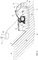
- the control unit 50 has a GPS navigation system 52, a topography memory 54, an autonomous steering system 56, a mobile radio interface 58, an electric gear motor 60 of the winding drive 36, an actuation arrangement 62 for adjusting the cable arm 38, and a further actuation arrangement 64 for adjusting the ejection tower 22 and a transponder unit 66 in connection.
- control unit 50 The method according to the invention carried out by the control unit 50 will be described below with reference to the in Fig. 3 and Fig. 4 illustrated machining situations are described in detail.
- the power supply line 34 is detachably connected to a transformer station 74 located in the edge region 70 of the field 72 to be worked by means of a power plug connector 68 attached to it, in order to convert the To feed power supply line 34 with electrical energy.
- the transformer station 74 is connected to a transmission line 76 and comprises a transformer (not shown) for providing a medium voltage in the order of 4,000 to 8,000 volts.
- the forage harvester 10 is initially in an in Fig. 3 or. Fig. 4 starting position, not shown, away from the field to be worked 72.
- the entire harvesting process is in one in Fig. 3 first machining section or cycle 78 shown in FIG Fig. 4 illustrated second machining section or cycle 80 divided.
- the processing sections 78, 80 are traversed automatically by means of the autonomous steering system 56 on the basis of the data provided by the GPS navigation system 52 and the topography memory 54.
- the forage harvester 10 is moved from its starting position to the field 72.
- the energy supply line 34 is laid down along the head end of the field 72 up to the starting point of the first processing section 78.
- the forage harvester 10 then begins to travel through the first processing section 78.
- the electric gear motor 60 of the winding drive 36 in conjunction with the actuation arrangement 62 of the cable arm 38 is controlled by the control unit 50 in such a way that the energy supply line 34 is in a harvested area 82 behind the header 18 is deposited between the forage harvester 10 and an area 84 still to be harvested offset from the lane of the forage harvester 10 on the arable surface 42 (see FIG Fig. 3 ).
- the electric geared motor 60 of the winding drive 36 in connection with the actuation arrangement 62 of the cable arm 38 of the control unit 50 is moved along the second processing section 80 adjoining or overlapping the first processing section 78 controlled that the energy supply line 34 is resumed in the harvested area 82 (see Fig. 4 ).
- the forage harvester 10 moves to the next first processing section 78.
- the energy supply line 34 is further laid down along the head end of the field 72 to the starting point of the next first processing section 78 and the harvesting process is resumed.
- the forage harvester 10 then returns to its original starting position, taking up the power supply line 34 at the head end of the field 72, so that it can be loaded after loosening the power connector 68 and stowing the power supply line 34 and taken to the next site. More precisely, the power supply line 34 is stored by the control unit 50 on the basis of the data provided by the GPS navigation system 52 and the topography memory 54 along the first processing section 78 on a defined, namely GPS-positioned cable path, and from there when the next row of plants is harvested second processing section 80 is resumed without overlapping with the lane of the forage harvester 10 or the vehicle combination 28. The energy supply line 34 is deposited in such a way that the vehicle combination 28 can maintain a sufficient distance along the second processing section 80 when the chopped crop is overloaded.
- the vehicle combination 28 is always located on the side of the forage harvester 10 facing the harvested area 82.
- the discharge tower 22 is moved to the opposite side of the forage harvester when driving through the headland, i.e. when turning from the control unit 50 by activating the further actuation arrangement 64 via the cable arm 38 Forage harvester 10 pivoted.
- the electric geared motor 60 of the winding drive 36 in connection with the actuation arrangement 62 is controlled by the control unit 50 when driving through the headland in such a way that the energy supply line 34 is tracked essentially free of tensile force during the transition from the first processing section 78 to the second processing section 80.
- the energy supply line 34 is essentially free of tensile force when it largely maintains its position between the two processing sections 78, 80 during the turning process in the headland, so that the The next row of plants to be harvested is not damaged by undesired changes in position.
- the control unit 50 places it on the field surface 42 as a function of the driving speed, while maintaining a predetermined maximum tensile force.
- the current tensile force is estimated by the control unit 50 on the basis of the exit angle of the energy supply line 34 in the area of the guide element 44 on the cable arm 38 by means of a sensor arrangement (not shown).
- the current travel speed is obtained, for example, by evaluating the data provided by the GPS navigation system 52.
- a distance signal fed in or modulated on by the control unit 50 by means of the transponder unit 66 is sent from the power supply line 34, which is provided for the contactless derivation of a safety distance to be maintained with respect to the power supply line 34.
- the vehicle combination 28 is equipped with a corresponding receiving unit in order to use the received distance signal to estimate whether the safety distance is not being exceeded.
- An excessive approach of the vehicle combination 28 to the energy supply line 34 can thus be recognized and averted by taking suitable countermeasures. These take place in the form of a corrective steering intervention carried out by a vehicle controller or emergency stop of the vehicle combination 28 and, if applicable, of the forage harvester 10, in which case a corresponding exchange of information takes place via the mobile radio interface 58.
Landscapes
- Engineering & Computer Science (AREA)
- Life Sciences & Earth Sciences (AREA)
- Environmental Sciences (AREA)
- Mechanical Engineering (AREA)
- Sustainable Development (AREA)
- Sustainable Energy (AREA)
- Power Engineering (AREA)
- Transportation (AREA)
- Soil Sciences (AREA)
- Architecture (AREA)
- Structural Engineering (AREA)
- Civil Engineering (AREA)
- Computer Networks & Wireless Communication (AREA)
- Signal Processing (AREA)
- Agricultural Machines (AREA)
- Current-Collector Devices For Electrically Propelled Vehicles (AREA)
- Control Of Position, Course, Altitude, Or Attitude Of Moving Bodies (AREA)
Description
- Die Erfindung bezieht sich auf ein Verfahren zur Energieversorgung eines kabelgebunden betriebenen Feldhäckslers.
- Die aufkommende Elektrifizierung in der Landwirtschaftstechnik bietet gegenüber konventionellen Antrieben, die auf der Verwendung von Dieselmotoren beruhen, die Möglichkeit, höhere Antriebsleistungen bei zugleich geringerem Bauraumbedarf zu verwirklichen. Dies bietet sich vor allem bei leistungsintensiven Bearbeitungsprozessen an, wie sie insbesondere für den Betrieb eines Feldhäckslers typisch sind. Der Leistungsbedarf kann je nach dem Durchsatzvermögen des Feldhäckslers bis zu einige Megawatt betragen. Eine Möglichkeit der elektrischen Versorgung eines derartigen Feldhäckslers mit ausreichender Leistung besteht im kabelgebundenen Betrieb.
-
CN 105 746 076 zeigt eine elektrisch betriebene Erntemaschine. - Es ist Aufgabe der vorliegenden Erfindung, ein Verfahren der eingangs genannten Art anzugeben, das einen zuverlässigen Betrieb eines kabelgebunden betriebenen Feldhäckslers erlaubt.
- Diese Aufgabe wird durch ein Verfahren mit den Merkmalen des Patentanspruchs 1 gelöst.
- Bei dem Verfahren zur Energieversorgung eines kabelgebunden betriebenen Feldhäckslers umfasst der Feldhäcksler eine Kabeltrommel zur Aufnahme einer Energieversorgungsleitung, einen mit der Kabeltrommel verbundenen Wickelantrieb zum Auf- und Abspulen der Energieversorgungsleitung, einen mittels einer Betätigungsanordnung bezüglich seiner Orientierung und/oder Ausfahrlänge verstellbaren Kabelarm im Heckbereich des Feldhäckslers, welcher der geführten Ablage bzw. Aufnahme der Energieversorgungsleitung entlang einer zu befahrenden Ackeroberfläche dient, und einen über den Kabelarm hinweg verschwenkbaren Auswurfturm zum Überladen gehäckselten Ernteguts auf ein nebenher fahrendes Transportfahrzeug. Erfindungsgemäß wird der Wickelantrieb in Verbindung mit der Betätigungsanordnung des Kabelarms entlang eines ersten Bearbeitungsabschnitts von einer Kontrolleinheit derart angesteuert, dass die Energieversorgungsleitung in einem abgeernteten Bereich zwischen dem Feldhäcksler und einem noch abzuerntenden Bereich versetzt zur Fahrspur des Feldhäckslers auf der Ackeroberfläche abgelegt wird, und nach Durchfahren eines Vorgewendes entlang eines an den ersten Bearbeitungsabschnitt angrenzenden bzw. diesen überschneidenden zweiten Bearbeitungsabschnitts in dem abgeernteten Bereich von der Ackeroberfläche wieder aufgenommen wird.
- Mit anderen Worten wird die Energieversorgungsleitung entlang des ersten Bearbeitungsabschnitts auf einem definierten, insbesondere GPS-positionierten Kabelpfad abgelegt und von dort beim Abernten der angrenzenden Pflanzenreihe entlang des zweiten Bearbeitungsabschnitts wieder aufgenommen, ohne dass es zu Überschneidungen mit der Fahrspur des Feldhäckslers oder des Transportfahrzeugs kommt. Das Transportfahrzeug befindet sich dabei stets auf der dem abgeernteten Bereich zugewandten Seite des Feldhäckslers. Dementsprechend wird der Auswurfturm beim Durchfahren des Vorgewendes, also beim Wenden über den Kabelarm hinweg auf die gegenüberliegende Seite des Feldhäckslers geschwenkt. Die Ablage der Energieversorgungsleitung erfolgt derart, dass entlang des zweiten Bearbeitungsabschnitts beim Überladen des gehäckselten Ernteguts stets ein ausreichender Abstand gegenüber dem Transportfahrzeug eingehalten werden kann.
- Während des gesamten Erntevorgangs werden die beiden Bearbeitungsabschnitte periodisch hintereinander durchlaufen, bis die komplette Ackeroberfläche streifenförmig abgeerntet worden ist.
- Vorteilhafte Ausgestaltungen des erfindungsgemäßen Verfahrens gehen aus den Unteransprüchen hervor.
- Vorzugweise wird der Wickelantrieb in Verbindung mit der Betätigungsanordnung des Kabelarms von der Kontrolleinheit beim Durchfahren des Vorgewendes zwischen dem ersten und zweiten Bearbeitungsabschnitt derart angesteuert, dass die Energieversorgungsleitung beim Übergang vom ersten zum zweiten Bearbeitungsabschnitt im Wesentlichen zugkraftfrei nachgeführt wird. Definitionsgemäß ist die Energieversorgungleitung im Wesentlichen dann zugkraftfrei, wenn diese während des Wendevorgangs im Vorgewende ihre Lage zwischen den beiden Bearbeitungsabschnitten weitgehend beibehält, mithin die nächste abzuerntende Pflanzenreihe nicht durch unerwünschte Lageänderungen beschädigt wird.
- Um eine mechanische Überlastung der Energieversorgungsleitung zu vermeiden, besteht die Möglichkeit, dass die Energieversorgungsleitung fahrtgeschwindigkeitsabhängig, insbesondere unter Einhaltung einer vorgegebenen Höchstzugkraft auf der Ackeroberfläche abgelegt wird. Die aktuelle Zugkraft kann von der Kontrolleinheit insbesondere anhand des Austrittswinkels der Energieversorgungsleitung im Bereich eines Führungselements am Kabelarm abgeschätzt werden. Insofern sei auf die aus der
DE 10 2017 201 544 A1 bekannte Sensoranordnung hingewiesen. - Typischerweise wird die Energieversorgungsleitung seitens einer Umspannstation mit elektrischer Energie gespeist. Diese befindet sich im Randbereich des zu bearbeitenden Ackers und steht insbesondere mit einer Überlandleitung in Verbindung. Die Umspannstation weist im Allgemeinen einen Umspanntransformator zur Bereitstellung einer Mittelspannung in der Größenordnung von 4000 bis 8000 Volt auf, sodass die Übertragung ausreichender elektrischer Leistungen bei zugleich akzeptablen Leitungsdurchmessern gewährleistet ist. Die Energieversorgungsleitung ist mittels eines Leistungssteckverbinders lösbar an der Umspannstation angeschlossen.
- Auch ist es denkbar, dass über die Energieversorgungsleitung ein Abstandssignal ausgesandt wird, das zur berührungslosen Ableitung eines gegenüber der Energieversorgungsleitung einzuhaltenden Sicherheitsabstands vorgesehen ist. So lässt sich beispielsweise eine übermäßige Annäherung des Transportfahrzeugs an die Energieversorgungsleitung erkennen und durch Einleitung geeigneter Gegenmaßnahmen abwenden. Diese können beispielsweise in Form eines von einer Fahrzeugsteuerung durchgeführten korrigierenden Lenkeingriffs oder Notstopps des Transportfahrzeugs sowie gegebenenfalls des Feldhäckslers erfolgen.
- Das erfindungsgemäße Verfahren wird im Folgenden anhand der beigefügten Zeichnungen näher erläutert. Hierbei sind übereinstimmende oder bezüglich ihrer Funktion vergleichbare Komponenten mit denselben Bezugszeichen gekennzeichnet. Es zeigen:
- Fig. 1
- eine perspektivische Ansicht eines kabelgebunden betriebenen Feldhäckslers,
- Fig. 2
- ein Ausführungsbeispiel einer Anordnung zur Durchführung des erfindungsgemäßen Verfahrens für den kabelgebunden betriebenen Feldhäcksler in
Fig. 1 , - Fig. 3
- der in
Fig. 1 wiedergegebene Feldhäcksler beim Durchfahren eines ersten Bearbeitungsabschnitts auf einem Acker, und - Fig. 4
- der in
Fig. 1 wiedergegebene Feldhäcksler beim Durchfahren eines auf den ersten Bearbeitungsabschnitt folgenden zweiten Bearbeitungsabschnitts. -
Fig. 1 zeigt eine perspektivische Ansicht eines kabelgebunden betriebenen Feldhäckslers. - Der Feldhäcksler 10 weist ein Chassis 12 auf, das von angetriebenen Vorderrädern 14 und lenkbaren Hinterrädern 16 getragen wird. Ein Erntevorsatz 18 dient der Aufnahme von zu häckselndem Erntegut, wobei dieses innerhalb des Feldhäckslers 10 zerkleinert und einem bezüglich einer in etwa vertikalen Fahrzeugachse 20 und in seiner Neigung verstellbaren Auswurfturm 22 zum Überladen auf ein nebenher fahrendes Transportfahrzeug zugeführt wird. Letzteres weist die Gestalt eines aus einem landwirtschaftlichen Traktor 24 sowie einem von diesem gezogenen Überladewagen 26 bestehenden Fahrzeuggespanns 28 auf (siehe
Fig. 3 und4 ). Bei dem Erntegut handelt es sich beispielsweise um Mais, Gras oder Luzerne. - Entsprechend der Darstellung in
Fig. 2 ist der Feldhäcksler 10 vorliegend mit einem elektrischen Betriebsaggregat 30 zum Antreiben der Vorderräder 14 sowie zur Zufuhr und Verarbeitung des zu häckselnden Ernteguts ausgerüstet, wobei das Betriebsaggregat 30 mittels einer auf einer Kabeltrommel 32 befindlichen Energieversorgungsleitung 34 in Gestalt eines mehrpoligen elektrischen Kabels mit elektrischem Strom versorgt wird. Ein mit der Kabeltrommel 32 verbundener Wickelantrieb 36 ermöglicht ein gezieltes Auf- und Abspulen der Energieversorgungsleitung 34, wobei ein bezüglich seiner Orientierung und/oder Ausfahrlänge verstellbarer Kabelarm 38 im Heckbereich 40 des Feldhäckslers 10 vorgesehen ist, welcher der geführten Ablage bzw. Aufnahme der Energieversorgungsleitung 34 entlang einer zu befahrenden Ackeroberfläche 42 dient und zu diesem Zweck ein Führungselement 44 aufweist. Bei der Kabeltrommel 32 handelt es sich um eine luftgekühlte Ausführung, wie sie aus derDE 10 2017 215 822 A1 hervorgeht. - In einem im Heckbereich 40 des Feldhäckslers 10 angeordneten Schaltschrank 46 ist eine in
Fig. 2 im Detail wiedergegebene Anordnung 48 untergebracht, die eine mikroprozessorgesteuerte Kontrolleinheit 50 aufweist, die der Durchführung des erfindungsgemäßen Verfahrens dient. - Die Kontrolleinheit 50 steht mit einem GPS-Navigationssystem 52, einem Topografiespeicher 54, einem autonomen Lenksystem 56, einer Mobilfunkschnittstelle 58, einem elektrischen Getriebemotor 60 des Wickelantriebs 36, einer Betätigungsanordnung 62 zum Verstellen des Kabelarms 38, einer weiteren Betätigungsanordnung 64 zum Verstellen des Auswurfturms 22 sowie einer Transpondereinheit 66 in Verbindung.
- Das von der Kontrolleinheit 50 durchgeführte erfindungsgemäße Verfahren soll nachfolgend unter Bezugnahme auf die in
Fig. 3 undFig. 4 dargestellten Bearbeitungssituationen im Detail beschrieben werden. - Zu Beginn des Erntevorgangs wird die Energieversorgungsleitung 34 mittels eines daran angebrachten Leistungssteckverbinders 68 lösbar an einer im Randbereich 70 des zu bearbeitenden Ackers 72 befindlichen Umspannstation 74 angeschlossen, um die Energieversorgungsleitung 34 mit elektrischer Energie zu speisen. Die Umspannstation 74 steht mit einer Überlandleitung 76 in Verbindung und umfasst einen (nicht gezeigten) Umspanntransformator zur Bereitstellung einer Mittelspannung in der Größenordnung von 4000 bis 8000 Volt. Der Feldhäcksler 10 befindet sich dabei zunächst in einer in
Fig. 3 bzw.Fig. 4 nicht wiedergegebenen Ausgangsposition abseits des zu bearbeitenden Ackers 72. - Der gesamte Erntevorgang ist in einen in
Fig. 3 dargestellten ersten Bearbeitungsabschnitt bzw. -zyklus 78 und einen inFig. 4 dargestellten zweiten Bearbeitungsabschnitt bzw. -zyklus 80 aufgeteilt. Das Durchfahren der Bearbeitungsabschnitte 78, 80 erfolgt selbsttätig mittels des autonomen Lenksystems 56 auf Grundlage der von dem GPS-Navigationssystem 52 sowie dem Topografiespeicher 54 bereitgestellten Daten. - Zur Durchführung des eigentlichen Erntevorgangs wird der Feldhäcksler 10 aus seiner Ausgangsposition an den Acker 72 herangefahren. Dabei wird die Energieversorgungsleitung 34 entlang des Kopfendes des Ackers 72 bis zum Startpunkt des ersten Bearbeitungsabschnitts 78 abgelegt. Danach beginnt der Feldhäcksler 10 mit dem Durchfahren des ersten Bearbeitungsabschnitts 78.
- Entlang des ersten Bearbeitungsabschnitts 78 wird der elektrische Getriebemotor 60 des Wickelantriebs 36 in Verbindung mit der Betätigungsanordnung 62 des Kabelarms 38 von der Kontrolleinheit 50 derart angesteuert, dass die Energieversorgungsleitung 34 in einem abgeernteten Bereich 82 hinter dem Erntevorsatz 18 zwischen dem Feldhäcksler 10 und einem noch abzuerntenden Bereich 84 versetzt zur Fahrspur des Feldhäckslers 10 auf der Ackeroberfläche 42 abgelegt wird (siehe
Fig. 3 ). - Nach Erreichen des Kopfendes des Ackers 72 und Durchfahren eines nicht gezeigten Vorgewendes wird entlang des an den ersten Bearbeitungsabschnitt 78 angrenzenden bzw. diesen überlappenden zweiten Bearbeitungsabschnitts 80 der elektrische Getriebemotor 60 des Wickelantriebs 36 in Verbindung mit der Betätigungsanordnung 62 des Kabelarms 38 von der Kontrolleinheit 50 derart angesteuert, dass die Energieversorgungsleitung 34 in dem abgeernteten Bereich 82 wieder aufgenommen wird (siehe
Fig. 4 ). - Am Ende des zweiten Bearbeitungsabschnitts 80 fährt der Feldhäcksler 10 zum nächsten ersten Bearbeitungsabschnitt 78. Dabei wird die Energieversorgungsleitung 34 weiter entlang des Kopfendes des Ackers 72 bis zum Startpunkt des nächsten ersten Bearbeitungsabschnitts 78 abgelegt und der Erntevorgang wird erneut aufgenommen.
- Dieser Vorgang wiederholt sich, bis die komplette Ackeroberfläche 42 streifenförmig abgeerntet worden ist. Anschließend kehrt der Feldhäcksler 10 unter Aufnahme der Energieversorgungsleitung 34 am Kopfende des Ackers 72 zu seiner ursprünglichen Ausgangsposition zurück, um nach Lösen der Leistungssteckverbinders 68 und Verstauen der Energieversorgungsleitung 34 verladen sowie zum nächsten Einsatzort gebracht zu werden. Genauer gesagt wird die Energieversorgungsleitung 34 von der Kontrolleinheit 50 auf Grundlage der von dem GPS-Navigationssystem 52 sowie dem Topografiespeicher 54 bereitgestellten Daten entlang des ersten Bearbeitungsabschnitts 78 auf einem definierten, nämlich GPS-positionierten Kabelpfad abgelegt und von dort beim Abernten der nächsten Pflanzenreihe entlang des zweiten Bearbeitungsabschnitts 80 wieder aufgenommen, ohne dass es zu Überschneidungen mit der Fahrspur des Feldhäckslers 10 oder des Fahrzeuggespanns 28 kommt. Die Ablage der Energieversorgungsleitung 34 erfolgt derart, dass entlang des zweiten Bearbeitungsabschnitts 80 beim Überladen des gehäckselten Ernteguts ein ausreichender Abstand seitens des Fahrzeuggespanns 28 eingehalten werden kann.
- Das Fahrzeuggespann 28 befindet sich stets auf der dem abgeernteten Bereich 82 zugewandten Seite des Feldhäckslers 10. Der Auswurfturm 22 wird beim Durchfahren des Vorgewendes, also beim Wenden von der Kontrolleinheit 50 durch Ansteuerung der weiteren Betätigungsanordnung 64 über den Kabelarm 38 hinweg auf die gegenüberliegende Seite des Feldhäckslers 10 geschwenkt.
- Des Weiteren wird der elektrische Getriebemotor 60 des Wickelantriebs 36 in Verbindung mit der Betätigungsanordnung 62 von der Kontrolleinheit 50 beim Durchfahren des Vorgewendes derart angesteuert, dass die Energieversorgungsleitung 34 beim Übergang vom ersten Bearbeitungsabschnitt 78 zum zweiten Bearbeitungsabschnitt 80 im wesentlichen zugkraftfrei nachgeführt wird. Definitionsgemäß ist die Energieversorgungsleitung 34 im Wesentlichen dann zugkraftfrei, wenn diese während des Wendevorgangs im Vorgewende ihre Lage zwischen den beiden Bearbeitungsabschnitten 78, 80 weitgehend beibehält, sodass die nächste abzuerntende Pflanzenreihe nicht durch unerwünschte Lageänderungen beschädigt wird.
- Um eine mechanische Überlastung der Energieversorgungsleitung 34 zu vermeiden, wird diese von der Kontrolleinheit 50 fahrtgeschwindigkeitsabhängig, und zwar unter Einhaltung einer vorgegebenen Höchstzugkraft auf der Ackeroberfläche 42 abgelegt. Die aktuelle Zugkraft wird von der Kontrolleinheit 50 anhand des Austrittswinkels der Energieversorgungsleitung 34 im Bereich des Führungselements 44 am Kabelarm 38 mittels einer nicht gezeigten Sensoranordnung abgeschätzt. Die aktuelle Fahrtgeschwindigkeit ergibt sich beispielsweise durch Auswertung der von dem GPS-Navigationssystem 52 bereitgestellten Daten.
- Optional wird von der Energieversorgungsleitung 34 ein von der Kontrolleinheit 50 mittels der Transpondereinheit 66 eingespeistes bzw. aufmoduliertes Abstandssignal ausgesandt, das zur berührungslosen Ableitung eines gegenüber der Energieversorgungsleitung 34 einzuhaltenden Sicherheitsabstands vorgesehen ist. Das Fahrzeuggespann 28 ist in diesem Fall mit einer entsprechenden Empfangseinheit ausgerüstet, um anhand des empfangenen Abstandssignals abzuschätzen, ob der Sicherheitsabstand unterschritten wird. So lässt sich eine übermäßige Annäherung des Fahrzeuggespanns 28 an die Energieversorgungsleitung 34 erkennen und durch Einleitung geeigneter Gegenmaßnahmen abwenden. Diese erfolgen in Form eines von einer Fahrzeugsteuerung durchgeführten korrigierenden Lenkeingriffs oder Notstopps des Fahrzeuggespanns 28 sowie gegebenenfalls des Feldhäckslers 10, wobei in letzterem Fall ein entsprechender Informationsaustausch über die Mobilfunkschnittstelle 58 erfolgt.
Claims (5)
- Verfahren zur Energieversorgung eines kabelgebunden betriebenen Feldhäckslers, mit einer Kabeltrommel (32) zur Aufnahme einer Energieversorgungsleitung (34), einem mit der Kabeltrommel (32) verbundenen Wickelantrieb (36) zum Auf- und Abspulen der Energieversorgungsleitung (34), einem mittels einer Betätigungsanordnung (62) bezüglich seiner Orientierung und/oder Ausfahrlänge verstellbaren Kabelarm (38) im Heckbereich (40) des Feldhäckslers (10), welcher der geführten Ablage bzw. Aufnahme der Energieversorgungsleitung (34) entlang einer zu befahrenden Ackeroberfläche (42) dient, und einem über den Kabelarm (38) hinweg verschwenkbaren Auswurfturm (22) zum Überladen gehäckselten Ernteguts auf ein nebenher fahrendes Transportfahrzeug (28), wobei der Wickelantrieb (36) in Verbindung mit der Betätigungsanordnung (62) des Kabelarms (38) entlang eines ersten Bearbeitungsstreifens (78) von einer Kontrolleinheit (50) derart angesteuert wird, dass die Energieversorgungsleitung (34) in einem abgeernteten Bereich (82) zwischen dem Feldhäcksler (10) und einem noch abzuerntenden Bereich (84) versetzt zur Fahrspur des Feldhäckslers (10) auf der Ackeroberfläche (42) abgelegt wird, und nach Durchfahren eines Vorgewendes entlang eines an den ersten Bearbeitungsstreifen (78) angrenzenden bzw. diesen überschneidenden zweiten Bearbeitungsstreifens (80) in dem abgeernteten Bereich (82) von der Ackeroberfläche (42) wieder aufgenommen wird.
- Verfahren nach Anspruch 1, dadurch gekennzeichnet, dass der Wickelantrieb (36) in Verbindung mit der Betätigungsanordnung (62) des Kabelarms (38) von der Kontrolleinheit (50) beim Durchfahren des Vorgewendes zwischen dem ersten und zweiten Bearbeitungsabschnitt (78, 80) derart angesteuert wird, dass die Energieversorgungsleitung (34) beim Übergang vom ersten zum zweiten Bearbeitungsabschnitt (80) im Wesentlichen zugkraftfrei nachgeführt wird.
- Verfahren nach Anspruch 1 oder 2, dadurch gekennzeichnet, dass die Energieversorgungsleitung (34) fahrtgeschwindigkeitsabhängig, insbesondere unter Einhaltung einer vorgegebenen Höchstzugkraft auf der Ackeroberfläche (42) abgelegt wird.
- Verfahren nach wenigstens einem der Ansprüche 1 bis 3, dadurch gekennzeichnet, dass die Energieversorgungsleitung (34) seitens einer Umspannstation (74) mit elektrischer Energie gespeist wird.
- Verfahren nach wenigstens einem der Ansprüche 1 bis 4, dadurch gekennzeichnet, dass über die Energieversorgungsleitung (34) ein Abstandssignal ausgesandt wird, das zur berührungslosen Ableitung eines gegenüber der Energieversorgungsleitung (34) einzuhaltenden Sicherheitsabstands vorgesehen ist.
Applications Claiming Priority (1)
| Application Number | Priority Date | Filing Date | Title |
|---|---|---|---|
| DE102018212150.8A DE102018212150A1 (de) | 2018-07-20 | 2018-07-20 | Verfahren zur Energieversorgung eines kabelgebundenen betriebenen Feldhäckslers |
Publications (2)
| Publication Number | Publication Date |
|---|---|
| EP3597470A1 EP3597470A1 (de) | 2020-01-22 |
| EP3597470B1 true EP3597470B1 (de) | 2021-03-31 |
Family
ID=67262116
Family Applications (1)
| Application Number | Title | Priority Date | Filing Date |
|---|---|---|---|
| EP19185922.2A Active EP3597470B1 (de) | 2018-07-20 | 2019-07-12 | Verfahren zur energieversorgung eines kabelgebunden betriebenen feldhäckslers |
Country Status (3)
| Country | Link |
|---|---|
| US (1) | US11492229B2 (de) |
| EP (1) | EP3597470B1 (de) |
| DE (1) | DE102018212150A1 (de) |
Families Citing this family (67)
| Publication number | Priority date | Publication date | Assignee | Title |
|---|---|---|---|---|
| US10806079B2 (en) | 2018-02-26 | 2020-10-20 | Deere & Company | Automatic product harvesting method and control system |
| US12069978B2 (en) | 2018-10-26 | 2024-08-27 | Deere & Company | Predictive environmental characteristic map generation and control system |
| US11240961B2 (en) | 2018-10-26 | 2022-02-08 | Deere & Company | Controlling a harvesting machine based on a geo-spatial representation indicating where the harvesting machine is likely to reach capacity |
| US11079725B2 (en) | 2019-04-10 | 2021-08-03 | Deere & Company | Machine control using real-time model |
| US11672203B2 (en) | 2018-10-26 | 2023-06-13 | Deere & Company | Predictive map generation and control |
| US11589509B2 (en) | 2018-10-26 | 2023-02-28 | Deere & Company | Predictive machine characteristic map generation and control system |
| US11467605B2 (en) | 2019-04-10 | 2022-10-11 | Deere & Company | Zonal machine control |
| US11653588B2 (en) | 2018-10-26 | 2023-05-23 | Deere & Company | Yield map generation and control system |
| US11957072B2 (en) | 2020-02-06 | 2024-04-16 | Deere & Company | Pre-emergence weed detection and mitigation system |
| US11641800B2 (en) | 2020-02-06 | 2023-05-09 | Deere & Company | Agricultural harvesting machine with pre-emergence weed detection and mitigation system |
| US11178818B2 (en) | 2018-10-26 | 2021-11-23 | Deere & Company | Harvesting machine control system with fill level processing based on yield data |
| DE102019203653A1 (de) | 2019-03-18 | 2020-09-24 | Deere & Company | Stromversorgungssystem für eine Fahrzeugflotte |
| USD962998S1 (en) | 2019-03-18 | 2022-09-06 | Deere & Company | Hood for a work machine |
| US11234366B2 (en) | 2019-04-10 | 2022-02-01 | Deere & Company | Image selection for machine control |
| US12035648B2 (en) | 2020-02-06 | 2024-07-16 | Deere & Company | Predictive weed map generation and control system |
| US12329148B2 (en) | 2020-02-06 | 2025-06-17 | Deere & Company | Predictive weed map and material application machine control |
| US12225846B2 (en) | 2020-02-06 | 2025-02-18 | Deere & Company | Machine control using a predictive map |
| USD939592S1 (en) | 2020-03-05 | 2021-12-28 | Deere & Company | Work machine |
| DE102020203283A1 (de) | 2020-03-13 | 2021-09-16 | Deere & Company | Kabeltrommel zur Energieversorgung eines elektrisch betriebenen Nutzfahrzeugs |
| DE102020203282A1 (de) | 2020-03-13 | 2021-09-16 | Deere & Company | Kabeltrommel zur Energieversorgung eines elektrisch betriebenen Nutzfahrzeugs |
| US11477940B2 (en) | 2020-03-26 | 2022-10-25 | Deere & Company | Mobile work machine control based on zone parameter modification |
| US11946747B2 (en) | 2020-10-09 | 2024-04-02 | Deere & Company | Crop constituent map generation and control system |
| US11711995B2 (en) | 2020-10-09 | 2023-08-01 | Deere & Company | Machine control using a predictive map |
| US11675354B2 (en) | 2020-10-09 | 2023-06-13 | Deere & Company | Machine control using a predictive map |
| US12386354B2 (en) | 2020-10-09 | 2025-08-12 | Deere & Company | Predictive power map generation and control system |
| US11592822B2 (en) | 2020-10-09 | 2023-02-28 | Deere & Company | Machine control using a predictive map |
| US12419220B2 (en) | 2020-10-09 | 2025-09-23 | Deere & Company | Predictive map generation and control system |
| US11635765B2 (en) | 2020-10-09 | 2023-04-25 | Deere & Company | Crop state map generation and control system |
| US11927459B2 (en) | 2020-10-09 | 2024-03-12 | Deere & Company | Machine control using a predictive map |
| US11727680B2 (en) | 2020-10-09 | 2023-08-15 | Deere & Company | Predictive map generation based on seeding characteristics and control |
| US11825768B2 (en) | 2020-10-09 | 2023-11-28 | Deere & Company | Machine control using a predictive map |
| US11844311B2 (en) | 2020-10-09 | 2023-12-19 | Deere & Company | Machine control using a predictive map |
| US11849671B2 (en) | 2020-10-09 | 2023-12-26 | Deere & Company | Crop state map generation and control system |
| US11889788B2 (en) | 2020-10-09 | 2024-02-06 | Deere & Company | Predictive biomass map generation and control |
| US11474523B2 (en) | 2020-10-09 | 2022-10-18 | Deere & Company | Machine control using a predictive speed map |
| US11871697B2 (en) | 2020-10-09 | 2024-01-16 | Deere & Company | Crop moisture map generation and control system |
| US11650587B2 (en) | 2020-10-09 | 2023-05-16 | Deere & Company | Predictive power map generation and control system |
| US11983009B2 (en) | 2020-10-09 | 2024-05-14 | Deere & Company | Map generation and control system |
| US12178158B2 (en) | 2020-10-09 | 2024-12-31 | Deere & Company | Predictive map generation and control system for an agricultural work machine |
| US11845449B2 (en) | 2020-10-09 | 2023-12-19 | Deere & Company | Map generation and control system |
| US11895948B2 (en) | 2020-10-09 | 2024-02-13 | Deere & Company | Predictive map generation and control based on soil properties |
| US12013245B2 (en) | 2020-10-09 | 2024-06-18 | Deere & Company | Predictive map generation and control system |
| US11864483B2 (en) | 2020-10-09 | 2024-01-09 | Deere & Company | Predictive map generation and control system |
| US12069986B2 (en) | 2020-10-09 | 2024-08-27 | Deere & Company | Map generation and control system |
| US12422847B2 (en) | 2020-10-09 | 2025-09-23 | Deere & Company | Predictive agricultural model and map generation |
| US12550802B2 (en) | 2020-10-08 | 2026-02-17 | Deere & Company | Predictive machine characteristic map generation and control system |
| US11874669B2 (en) | 2020-10-09 | 2024-01-16 | Deere & Company | Map generation and control system |
| US11849672B2 (en) | 2020-10-09 | 2023-12-26 | Deere & Company | Machine control using a predictive map |
| US11889787B2 (en) | 2020-10-09 | 2024-02-06 | Deere & Company | Predictive speed map generation and control system |
| US12250905B2 (en) | 2020-10-09 | 2025-03-18 | Deere & Company | Machine control using a predictive map |
| CN112173847B (zh) * | 2020-10-27 | 2022-07-08 | 京广线缆集团有限公司 | 一种电缆回收用的去皮装置 |
| US12127500B2 (en) | 2021-01-27 | 2024-10-29 | Deere & Company | Machine control using a map with regime zones |
| CN113258367B (zh) * | 2021-05-13 | 2023-05-05 | 西华大学 | 一种农业适用的插线式供电装置 |
| SE2130191A1 (sv) * | 2021-07-08 | 2023-01-09 | Reuterstroem Karola | System för tillförsel av elektrisk energi till lantbruksmaskiner |
| DE102021120667A1 (de) | 2021-08-09 | 2023-02-09 | Deere & Company | Erntekette mit Übertragung elektrischer Energie von einem Transportfahrzeug auf eine Erntemaschine und Verfahren zu deren Betrieb |
| US12229886B2 (en) | 2021-10-01 | 2025-02-18 | Deere & Company | Historical crop state model, predictive crop state map generation and control system |
| US12310286B2 (en) | 2021-12-14 | 2025-05-27 | Deere & Company | Crop constituent sensing |
| US12302791B2 (en) | 2021-12-20 | 2025-05-20 | Deere & Company | Crop constituents, predictive mapping, and agricultural harvester control |
| US12245549B2 (en) | 2022-01-11 | 2025-03-11 | Deere & Company | Predictive response map generation and control system |
| US12520759B2 (en) | 2022-01-26 | 2026-01-13 | Deere & Company | Systems and methods for predicting material dynamics |
| US12082531B2 (en) | 2022-01-26 | 2024-09-10 | Deere & Company | Systems and methods for predicting material dynamics |
| US12295288B2 (en) | 2022-04-05 | 2025-05-13 | Deere &Company | Predictive machine setting map generation and control system |
| US12284934B2 (en) | 2022-04-08 | 2025-04-29 | Deere & Company | Systems and methods for predictive tractive characteristics and control |
| US12058951B2 (en) | 2022-04-08 | 2024-08-13 | Deere & Company | Predictive nutrient map and control |
| US12358493B2 (en) | 2022-04-08 | 2025-07-15 | Deere & Company | Systems and methods for predictive power requirements and control |
| US12582035B2 (en) | 2022-04-08 | 2026-03-24 | Deere & Company | Systems and methods for predictive power requirements and control |
| US12298767B2 (en) | 2022-04-08 | 2025-05-13 | Deere & Company | Predictive material consumption map and control |
Family Cites Families (11)
| Publication number | Priority date | Publication date | Assignee | Title |
|---|---|---|---|---|
| US7331436B1 (en) * | 2003-03-26 | 2008-02-19 | Irobot Corporation | Communications spooler for a mobile robot |
| FR2857515A1 (fr) * | 2003-07-12 | 2005-01-14 | Francois Remlinger | Dispositif de motorisation des engins de culture jardiniere par la force electrique du secteur urbain |
| DE102004031211A1 (de) * | 2004-06-28 | 2006-02-09 | Claas Selbstfahrende Erntemaschinen Gmbh | Verfahren und Vorrichtung zur Steuerung einer landwirtschaftlichen Arbeitsmaschine |
| IT1395238B1 (it) * | 2009-08-12 | 2012-09-05 | Orlando | Sistema agricolo a trazione funicolare a propulsione elettrica. |
| DE102014201203B4 (de) * | 2014-01-23 | 2026-05-07 | Deere & Company | Landwirtschaftliches Arbeitsfahrzeug mit einem Fluggerät und zugehöriger Stromversorgung |
| EP3001522B1 (de) * | 2014-06-26 | 2018-07-18 | Topy Kogyo Kabushiki Kaisha | Kabelsystem |
| JP2016082916A (ja) * | 2014-10-24 | 2016-05-19 | ヤンマー株式会社 | コンバイン |
| CN105723918B (zh) * | 2016-02-23 | 2017-06-27 | 杨松柏 | 一种履带式全喂入联合收割机 |
| CN105746076A (zh) * | 2016-04-22 | 2016-07-13 | 张飞 | 变频器控制型联合式收割机 |
| DE102017201544A1 (de) | 2017-01-31 | 2018-08-02 | Deere & Company | Anordnung zur Ermittlung einer räumlichen Orientierung eines von einer Kabeltrommel abgespulten Leitungsabschnitts |
| DE102017215822A1 (de) | 2017-09-07 | 2019-03-07 | Deere & Company | Kabeltrommel zur Energieversorgung eines elektrisch betriebenen Nutzfahrzeugs |
-
2018
- 2018-07-20 DE DE102018212150.8A patent/DE102018212150A1/de not_active Withdrawn
-
2019
- 2019-07-12 EP EP19185922.2A patent/EP3597470B1/de active Active
- 2019-07-19 US US16/516,669 patent/US11492229B2/en active Active
Non-Patent Citations (1)
| Title |
|---|
| None * |
Also Published As
| Publication number | Publication date |
|---|---|
| EP3597470A1 (de) | 2020-01-22 |
| US11492229B2 (en) | 2022-11-08 |
| US20200024102A1 (en) | 2020-01-23 |
| DE102018212150A1 (de) | 2020-01-23 |
Similar Documents
| Publication | Publication Date | Title |
|---|---|---|
| EP3597470B1 (de) | Verfahren zur energieversorgung eines kabelgebunden betriebenen feldhäckslers | |
| EP2936969B1 (de) | Kombination aus einem Zugfahrzeug und einer davon gezogenen Erntemaschine | |
| EP3412133A1 (de) | Bodenbearbeitungssystem mit mehreren ladestationen | |
| DE102014201203A1 (de) | Landwirtschaftliches Arbeitsfahrzeug mit einem Fluggerät und zugehöriger Stromversorgung | |
| DE102004052298A1 (de) | Überladeassistenzsystem | |
| EP3712003B1 (de) | Stromversorgungssystem eines flottenfahrzeugs | |
| DE19705842A1 (de) | Ernteverfahren | |
| DE102011121414A1 (de) | Verfahren und eine Vorrichtung zur Regelung einer Fahrt einer ersten selbstfahrenden Arbeitsmaschine in Bezug zu einer zweiten selbstfahrenden Arbeitsmaschine | |
| EP2636290A1 (de) | Landwirtschaftliches Anbaugerät | |
| DE102018212834A1 (de) | Anordnung zur selbsttätigen Kontrolle des Antriebs eines seitlich an einem Erntevorsatz angebrachten Elements, das zur Aufteilung des Ernteguts an der Grenze zwischen stehen bleibendem und abzuerntenden Bestand dient | |
| EP3257353B1 (de) | Landwirtschaftliche arbeitsmaschine und verfahren zum betrieb einer landwirtschaftlichen arbeitsmaschine | |
| DE102011083535A1 (de) | Selbstfahrende landwirtschaftliche Erntemaschine mit einem um eine vertikale Achse schwenkbaren Erntevorsatz | |
| EP2436252B1 (de) | Verfahren zum Betreiben einer Rechkreiselaushubsteuerung | |
| EP3300584B1 (de) | Landwirtschaftliche arbeitsmaschine und verfahren zum betrieb einer landwirtschaftlichen arbeitsmaschine | |
| EP0685146A1 (de) | Demontierbarer Erntebergungsvorsatz | |
| EP4252519A1 (de) | Landwirtschaftliche erntemaschine sowie verfahren zur steuerung einer landwirtschaftlichen erntemaschine | |
| DE102019111317A1 (de) | Autonome landwirtschaftliche Arbeitsmaschine und Verfahren zu deren Betrieb | |
| EP1013159A2 (de) | Steuerung für landwirtschaftliche Arbeitsmaschine | |
| EP1769662A1 (de) | Landwirtschaftliche Arbeitseinheit mit einem Arbeitsaggregat zum Erzeugen einer Objektreihe | |
| DE102013018820B4 (de) | Geräteträgersystem | |
| EP4268560B1 (de) | Autonome landwirtschaftliche arbeitsmaschine | |
| EP3791707A1 (de) | Vorrichtung zum bodennahen bearbeiten von pflanzlichem material und verfahren zum bodennahen bearbeiten von pflanzlichem material | |
| DE102017124480A1 (de) | Autonome landwirtschaftliche Robotervorrichtung | |
| DE102011121433A1 (de) | Verfahren und Vorrichtung zur Ansteuerung einer Landmaschine | |
| EP3906773A1 (de) | Landwirtschaftliche arbeitsmaschine umfassend eine hybride antriebsanordnung mit energiespeicher, wobei der ladezustand des energiespeichers auf basis einer prognose des zu erwartenden energiebedarfs geregelt wird |
Legal Events
| Date | Code | Title | Description |
|---|---|---|---|
| STAA | Information on the status of an ep patent application or granted ep patent |
Free format text: STATUS: UNKNOWN |
|
| PUAI | Public reference made under article 153(3) epc to a published international application that has entered the european phase |
Free format text: ORIGINAL CODE: 0009012 |
|
| STAA | Information on the status of an ep patent application or granted ep patent |
Free format text: STATUS: THE APPLICATION HAS BEEN PUBLISHED |
|
| AK | Designated contracting states |
Kind code of ref document: A1 Designated state(s): AL AT BE BG CH CY CZ DE DK EE ES FI FR GB GR HR HU IE IS IT LI LT LU LV MC MK MT NL NO PL PT RO RS SE SI SK SM TR |
|
| AX | Request for extension of the european patent |
Extension state: BA ME |
|
| STAA | Information on the status of an ep patent application or granted ep patent |
Free format text: STATUS: REQUEST FOR EXAMINATION WAS MADE |
|
| 17P | Request for examination filed |
Effective date: 20200722 |
|
| RBV | Designated contracting states (corrected) |
Designated state(s): AL AT BE BG CH CY CZ DE DK EE ES FI FR GB GR HR HU IE IS IT LI LT LU LV MC MK MT NL NO PL PT RO RS SE SI SK SM TR |
|
| GRAP | Despatch of communication of intention to grant a patent |
Free format text: ORIGINAL CODE: EPIDOSNIGR1 |
|
| STAA | Information on the status of an ep patent application or granted ep patent |
Free format text: STATUS: GRANT OF PATENT IS INTENDED |
|
| INTG | Intention to grant announced |
Effective date: 20201203 |
|
| RIN1 | Information on inventor provided before grant (corrected) |
Inventor name: LEHMANN, PHILIPP Inventor name: KEGEL, VOLKER Inventor name: TARASINSKI, NICOLAI Inventor name: BRILL, CHRISTIAN |
|
| GRAS | Grant fee paid |
Free format text: ORIGINAL CODE: EPIDOSNIGR3 |
|
| GRAA | (expected) grant |
Free format text: ORIGINAL CODE: 0009210 |
|
| STAA | Information on the status of an ep patent application or granted ep patent |
Free format text: STATUS: THE PATENT HAS BEEN GRANTED |
|
| AK | Designated contracting states |
Kind code of ref document: B1 Designated state(s): AL AT BE BG CH CY CZ DE DK EE ES FI FR GB GR HR HU IE IS IT LI LT LU LV MC MK MT NL NO PL PT RO RS SE SI SK SM TR |
|
| REG | Reference to a national code |
Ref country code: GB Ref legal event code: FG4D Free format text: NOT ENGLISH Ref country code: CH Ref legal event code: EP |
|
| REG | Reference to a national code |
Ref country code: DE Ref legal event code: R096 Ref document number: 502019001097 Country of ref document: DE Ref country code: AT Ref legal event code: REF Ref document number: 1376560 Country of ref document: AT Kind code of ref document: T Effective date: 20210415 |
|
| REG | Reference to a national code |
Ref country code: IE Ref legal event code: FG4D Free format text: LANGUAGE OF EP DOCUMENT: GERMAN |
|
| REG | Reference to a national code |
Ref country code: LT Ref legal event code: MG9D |
|
| PG25 | Lapsed in a contracting state [announced via postgrant information from national office to epo] |
Ref country code: NO Free format text: LAPSE BECAUSE OF FAILURE TO SUBMIT A TRANSLATION OF THE DESCRIPTION OR TO PAY THE FEE WITHIN THE PRESCRIBED TIME-LIMIT Effective date: 20210630 Ref country code: FI Free format text: LAPSE BECAUSE OF FAILURE TO SUBMIT A TRANSLATION OF THE DESCRIPTION OR TO PAY THE FEE WITHIN THE PRESCRIBED TIME-LIMIT Effective date: 20210331 Ref country code: BG Free format text: LAPSE BECAUSE OF FAILURE TO SUBMIT A TRANSLATION OF THE DESCRIPTION OR TO PAY THE FEE WITHIN THE PRESCRIBED TIME-LIMIT Effective date: 20210630 Ref country code: HR Free format text: LAPSE BECAUSE OF FAILURE TO SUBMIT A TRANSLATION OF THE DESCRIPTION OR TO PAY THE FEE WITHIN THE PRESCRIBED TIME-LIMIT Effective date: 20210331 |
|
| PG25 | Lapsed in a contracting state [announced via postgrant information from national office to epo] |
Ref country code: LV Free format text: LAPSE BECAUSE OF FAILURE TO SUBMIT A TRANSLATION OF THE DESCRIPTION OR TO PAY THE FEE WITHIN THE PRESCRIBED TIME-LIMIT Effective date: 20210331 Ref country code: RS Free format text: LAPSE BECAUSE OF FAILURE TO SUBMIT A TRANSLATION OF THE DESCRIPTION OR TO PAY THE FEE WITHIN THE PRESCRIBED TIME-LIMIT Effective date: 20210331 Ref country code: SE Free format text: LAPSE BECAUSE OF FAILURE TO SUBMIT A TRANSLATION OF THE DESCRIPTION OR TO PAY THE FEE WITHIN THE PRESCRIBED TIME-LIMIT Effective date: 20210331 |
|
| REG | Reference to a national code |
Ref country code: NL Ref legal event code: MP Effective date: 20210331 |
|
| PG25 | Lapsed in a contracting state [announced via postgrant information from national office to epo] |
Ref country code: NL Free format text: LAPSE BECAUSE OF FAILURE TO SUBMIT A TRANSLATION OF THE DESCRIPTION OR TO PAY THE FEE WITHIN THE PRESCRIBED TIME-LIMIT Effective date: 20210331 Ref country code: SM Free format text: LAPSE BECAUSE OF FAILURE TO SUBMIT A TRANSLATION OF THE DESCRIPTION OR TO PAY THE FEE WITHIN THE PRESCRIBED TIME-LIMIT Effective date: 20210331 Ref country code: LT Free format text: LAPSE BECAUSE OF FAILURE TO SUBMIT A TRANSLATION OF THE DESCRIPTION OR TO PAY THE FEE WITHIN THE PRESCRIBED TIME-LIMIT Effective date: 20210331 Ref country code: CZ Free format text: LAPSE BECAUSE OF FAILURE TO SUBMIT A TRANSLATION OF THE DESCRIPTION OR TO PAY THE FEE WITHIN THE PRESCRIBED TIME-LIMIT Effective date: 20210331 Ref country code: EE Free format text: LAPSE BECAUSE OF FAILURE TO SUBMIT A TRANSLATION OF THE DESCRIPTION OR TO PAY THE FEE WITHIN THE PRESCRIBED TIME-LIMIT Effective date: 20210331 |
|
| PG25 | Lapsed in a contracting state [announced via postgrant information from national office to epo] |
Ref country code: SK Free format text: LAPSE BECAUSE OF FAILURE TO SUBMIT A TRANSLATION OF THE DESCRIPTION OR TO PAY THE FEE WITHIN THE PRESCRIBED TIME-LIMIT Effective date: 20210331 Ref country code: PT Free format text: LAPSE BECAUSE OF FAILURE TO SUBMIT A TRANSLATION OF THE DESCRIPTION OR TO PAY THE FEE WITHIN THE PRESCRIBED TIME-LIMIT Effective date: 20210802 Ref country code: RO Free format text: LAPSE BECAUSE OF FAILURE TO SUBMIT A TRANSLATION OF THE DESCRIPTION OR TO PAY THE FEE WITHIN THE PRESCRIBED TIME-LIMIT Effective date: 20210331 Ref country code: PL Free format text: LAPSE BECAUSE OF FAILURE TO SUBMIT A TRANSLATION OF THE DESCRIPTION OR TO PAY THE FEE WITHIN THE PRESCRIBED TIME-LIMIT Effective date: 20210331 Ref country code: IS Free format text: LAPSE BECAUSE OF FAILURE TO SUBMIT A TRANSLATION OF THE DESCRIPTION OR TO PAY THE FEE WITHIN THE PRESCRIBED TIME-LIMIT Effective date: 20210731 |
|
| REG | Reference to a national code |
Ref country code: DE Ref legal event code: R097 Ref document number: 502019001097 Country of ref document: DE |
|
| PG25 | Lapsed in a contracting state [announced via postgrant information from national office to epo] |
Ref country code: ES Free format text: LAPSE BECAUSE OF FAILURE TO SUBMIT A TRANSLATION OF THE DESCRIPTION OR TO PAY THE FEE WITHIN THE PRESCRIBED TIME-LIMIT Effective date: 20210331 Ref country code: AL Free format text: LAPSE BECAUSE OF FAILURE TO SUBMIT A TRANSLATION OF THE DESCRIPTION OR TO PAY THE FEE WITHIN THE PRESCRIBED TIME-LIMIT Effective date: 20210331 Ref country code: DK Free format text: LAPSE BECAUSE OF FAILURE TO SUBMIT A TRANSLATION OF THE DESCRIPTION OR TO PAY THE FEE WITHIN THE PRESCRIBED TIME-LIMIT Effective date: 20210331 |
|
| PLBE | No opposition filed within time limit |
Free format text: ORIGINAL CODE: 0009261 |
|
| STAA | Information on the status of an ep patent application or granted ep patent |
Free format text: STATUS: NO OPPOSITION FILED WITHIN TIME LIMIT |
|
| 26N | No opposition filed |
Effective date: 20220104 |
|
| PG25 | Lapsed in a contracting state [announced via postgrant information from national office to epo] |
Ref country code: MC Free format text: LAPSE BECAUSE OF FAILURE TO SUBMIT A TRANSLATION OF THE DESCRIPTION OR TO PAY THE FEE WITHIN THE PRESCRIBED TIME-LIMIT Effective date: 20210331 |
|
| REG | Reference to a national code |
Ref country code: BE Ref legal event code: MM Effective date: 20210731 |
|
| PG25 | Lapsed in a contracting state [announced via postgrant information from national office to epo] |
Ref country code: IS Free format text: LAPSE BECAUSE OF FAILURE TO SUBMIT A TRANSLATION OF THE DESCRIPTION OR TO PAY THE FEE WITHIN THE PRESCRIBED TIME-LIMIT Effective date: 20210731 Ref country code: LU Free format text: LAPSE BECAUSE OF NON-PAYMENT OF DUE FEES Effective date: 20210712 |
|
| PG25 | Lapsed in a contracting state [announced via postgrant information from national office to epo] |
Ref country code: IE Free format text: LAPSE BECAUSE OF NON-PAYMENT OF DUE FEES Effective date: 20210712 Ref country code: BE Free format text: LAPSE BECAUSE OF NON-PAYMENT OF DUE FEES Effective date: 20210731 |
|
| REG | Reference to a national code |
Ref country code: CH Ref legal event code: PL |
|
| PG25 | Lapsed in a contracting state [announced via postgrant information from national office to epo] |
Ref country code: LI Free format text: LAPSE BECAUSE OF NON-PAYMENT OF DUE FEES Effective date: 20220731 Ref country code: CH Free format text: LAPSE BECAUSE OF NON-PAYMENT OF DUE FEES Effective date: 20220731 |
|
| PG25 | Lapsed in a contracting state [announced via postgrant information from national office to epo] |
Ref country code: CY Free format text: LAPSE BECAUSE OF FAILURE TO SUBMIT A TRANSLATION OF THE DESCRIPTION OR TO PAY THE FEE WITHIN THE PRESCRIBED TIME-LIMIT Effective date: 20210331 |
|
| PG25 | Lapsed in a contracting state [announced via postgrant information from national office to epo] |
Ref country code: HU Free format text: LAPSE BECAUSE OF FAILURE TO SUBMIT A TRANSLATION OF THE DESCRIPTION OR TO PAY THE FEE WITHIN THE PRESCRIBED TIME-LIMIT; INVALID AB INITIO Effective date: 20190712 Ref country code: GR Free format text: LAPSE BECAUSE OF FAILURE TO SUBMIT A TRANSLATION OF THE DESCRIPTION OR TO PAY THE FEE WITHIN THE PRESCRIBED TIME-LIMIT Effective date: 20210331 |
|
| PG25 | Lapsed in a contracting state [announced via postgrant information from national office to epo] |
Ref country code: MK Free format text: LAPSE BECAUSE OF FAILURE TO SUBMIT A TRANSLATION OF THE DESCRIPTION OR TO PAY THE FEE WITHIN THE PRESCRIBED TIME-LIMIT Effective date: 20210331 |
|
| PG25 | Lapsed in a contracting state [announced via postgrant information from national office to epo] |
Ref country code: TR Free format text: LAPSE BECAUSE OF FAILURE TO SUBMIT A TRANSLATION OF THE DESCRIPTION OR TO PAY THE FEE WITHIN THE PRESCRIBED TIME-LIMIT Effective date: 20210331 |
|
| PG25 | Lapsed in a contracting state [announced via postgrant information from national office to epo] |
Ref country code: MT Free format text: LAPSE BECAUSE OF FAILURE TO SUBMIT A TRANSLATION OF THE DESCRIPTION OR TO PAY THE FEE WITHIN THE PRESCRIBED TIME-LIMIT Effective date: 20210331 |
|
| REG | Reference to a national code |
Ref country code: AT Ref legal event code: MM01 Ref document number: 1376560 Country of ref document: AT Kind code of ref document: T Effective date: 20240712 |
|
| PGFP | Annual fee paid to national office [announced via postgrant information from national office to epo] |
Ref country code: DE Payment date: 20250620 Year of fee payment: 7 |
|
| PGFP | Annual fee paid to national office [announced via postgrant information from national office to epo] |
Ref country code: IT Payment date: 20250721 Year of fee payment: 7 |
|
| PGFP | Annual fee paid to national office [announced via postgrant information from national office to epo] |
Ref country code: GB Payment date: 20250728 Year of fee payment: 7 |
|
| PG25 | Lapsed in a contracting state [announced via postgrant information from national office to epo] |
Ref country code: AT Free format text: LAPSE BECAUSE OF NON-PAYMENT OF DUE FEES Effective date: 20240712 |
|
| PGFP | Annual fee paid to national office [announced via postgrant information from national office to epo] |
Ref country code: FR Payment date: 20250725 Year of fee payment: 7 |
|
| PGFP | Annual fee paid to national office [announced via postgrant information from national office to epo] |
Ref country code: AT Payment date: 20260410 Year of fee payment: 5 |