EP3597462B1 - Elektrische fahrzeugachsenvorrichtung - Google Patents
Elektrische fahrzeugachsenvorrichtung Download PDFInfo
- Publication number
- EP3597462B1 EP3597462B1 EP19186546.8A EP19186546A EP3597462B1 EP 3597462 B1 EP3597462 B1 EP 3597462B1 EP 19186546 A EP19186546 A EP 19186546A EP 3597462 B1 EP3597462 B1 EP 3597462B1
- Authority
- EP
- European Patent Office
- Prior art keywords
- housing
- joining areas
- dimensional joining
- dimensional
- vehicle axle
- Prior art date
- Legal status (The legal status is an assumption and is not a legal conclusion. Google has not performed a legal analysis and makes no representation as to the accuracy of the status listed.)
- Active
Links
Images


Classifications
-
- H—ELECTRICITY
- H02—GENERATION; CONVERSION OR DISTRIBUTION OF ELECTRIC POWER
- H02K—DYNAMO-ELECTRIC MACHINES
- H02K5/00—Casings; Enclosures; Supports
- H02K5/04—Casings or enclosures characterised by the shape, form or construction thereof
- H02K5/15—Mounting arrangements for bearing-shields or end plates
-
- B—PERFORMING OPERATIONS; TRANSPORTING
- B60—VEHICLES IN GENERAL
- B60K—ARRANGEMENT OR MOUNTING OF PROPULSION UNITS OR OF TRANSMISSIONS IN VEHICLES; ARRANGEMENT OR MOUNTING OF PLURAL DIVERSE PRIME-MOVERS IN VEHICLES; AUXILIARY DRIVES FOR VEHICLES; INSTRUMENTATION OR DASHBOARDS FOR VEHICLES; ARRANGEMENTS IN CONNECTION WITH COOLING, AIR INTAKE, GAS EXHAUST OR FUEL SUPPLY OF PROPULSION UNITS IN VEHICLES
- B60K1/00—Arrangement or mounting of electrical propulsion units
-
- F—MECHANICAL ENGINEERING; LIGHTING; HEATING; WEAPONS; BLASTING
- F16—ENGINEERING ELEMENTS AND UNITS; GENERAL MEASURES FOR PRODUCING AND MAINTAINING EFFECTIVE FUNCTIONING OF MACHINES OR INSTALLATIONS; THERMAL INSULATION IN GENERAL
- F16C—SHAFTS; FLEXIBLE SHAFTS; ELEMENTS OR CRANKSHAFT MECHANISMS; ROTARY BODIES OTHER THAN GEARING ELEMENTS; BEARINGS
- F16C35/00—Rigid support of bearing units; Housings, e.g. caps, covers
-
- H—ELECTRICITY
- H02—GENERATION; CONVERSION OR DISTRIBUTION OF ELECTRIC POWER
- H02K—DYNAMO-ELECTRIC MACHINES
- H02K5/00—Casings; Enclosures; Supports
- H02K5/04—Casings or enclosures characterised by the shape, form or construction thereof
- H02K5/16—Means for supporting bearings, e.g. insulating supports or means for fitting bearings in the bearing-shields
-
- H—ELECTRICITY
- H02—GENERATION; CONVERSION OR DISTRIBUTION OF ELECTRIC POWER
- H02K—DYNAMO-ELECTRIC MACHINES
- H02K7/00—Arrangements for handling mechanical energy structurally associated with dynamo-electric machines, e.g. structural association with mechanical driving motors or auxiliary dynamo-electric machines
- H02K7/10—Structural association with clutches, brakes, gears, pulleys or mechanical starters
- H02K7/116—Structural association with clutches, brakes, gears, pulleys or mechanical starters with gears
-
- B—PERFORMING OPERATIONS; TRANSPORTING
- B60—VEHICLES IN GENERAL
- B60K—ARRANGEMENT OR MOUNTING OF PROPULSION UNITS OR OF TRANSMISSIONS IN VEHICLES; ARRANGEMENT OR MOUNTING OF PLURAL DIVERSE PRIME-MOVERS IN VEHICLES; AUXILIARY DRIVES FOR VEHICLES; INSTRUMENTATION OR DASHBOARDS FOR VEHICLES; ARRANGEMENTS IN CONNECTION WITH COOLING, AIR INTAKE, GAS EXHAUST OR FUEL SUPPLY OF PROPULSION UNITS IN VEHICLES
- B60K1/00—Arrangement or mounting of electrical propulsion units
- B60K2001/001—Arrangement or mounting of electrical propulsion units one motor mounted on a propulsion axle for rotating right and left wheels of this axle
-
- B—PERFORMING OPERATIONS; TRANSPORTING
- B60—VEHICLES IN GENERAL
- B60Y—INDEXING SCHEME RELATING TO ASPECTS CROSS-CUTTING VEHICLE TECHNOLOGY
- B60Y2410/00—Constructional features of vehicle sub-units
- B60Y2410/10—Housings
-
- B—PERFORMING OPERATIONS; TRANSPORTING
- B60—VEHICLES IN GENERAL
- B60Y—INDEXING SCHEME RELATING TO ASPECTS CROSS-CUTTING VEHICLE TECHNOLOGY
- B60Y2410/00—Constructional features of vehicle sub-units
- B60Y2410/102—Shaft arrangements; Shaft supports, e.g. bearings
-
- F—MECHANICAL ENGINEERING; LIGHTING; HEATING; WEAPONS; BLASTING
- F16—ENGINEERING ELEMENTS AND UNITS; GENERAL MEASURES FOR PRODUCING AND MAINTAINING EFFECTIVE FUNCTIONING OF MACHINES OR INSTALLATIONS; THERMAL INSULATION IN GENERAL
- F16C—SHAFTS; FLEXIBLE SHAFTS; ELEMENTS OR CRANKSHAFT MECHANISMS; ROTARY BODIES OTHER THAN GEARING ELEMENTS; BEARINGS
- F16C2380/00—Electrical apparatus
- F16C2380/26—Dynamo-electric machines or combinations therewith, e.g. electro-motors and generators
-
- Y—GENERAL TAGGING OF NEW TECHNOLOGICAL DEVELOPMENTS; GENERAL TAGGING OF CROSS-SECTIONAL TECHNOLOGIES SPANNING OVER SEVERAL SECTIONS OF THE IPC; TECHNICAL SUBJECTS COVERED BY FORMER USPC CROSS-REFERENCE ART COLLECTIONS [XRACs] AND DIGESTS
- Y02—TECHNOLOGIES OR APPLICATIONS FOR MITIGATION OR ADAPTATION AGAINST CLIMATE CHANGE
- Y02T—CLIMATE CHANGE MITIGATION TECHNOLOGIES RELATED TO TRANSPORTATION
- Y02T10/00—Road transport of goods or passengers
- Y02T10/60—Other road transportation technologies with climate change mitigation effect
- Y02T10/64—Electric machine technologies in electromobility
Definitions
- the invention relates to an electric vehicle axle device for an automobile.
- Electric vehicle axle devices for motor vehicles conventionally have an electric machine, power electronics for controlling the electric machine, and a transmission coupled to the electric machine.
- the electric vehicle axle device has a housing in which at least the electric machine and the transmission are accommodated.
- the transmission has a plurality of bearings which are positioned by a positioning device with respect to a bearing cap fixed to the housing.
- the positioning device is formed by a pair of dowel pins or dowel bolts, which are arranged arbitrarily in an edge region of the housing and protrude from the housing at a vertical angle.
- the cover to be placed on the housing has corresponding bores into which the dowel pins or dowel bolts of the housing can be inserted.
- DE 10 2013 204 776 A1 discloses an electric vehicle axle device having at least one vehicle axle to which vehicle wheels are attachable, and wherein the electric vehicle axle device has a transmission connected to the vehicle axle. Furthermore, the vehicle axle device has an electric motor, which is coupled to the transmission, for the transmission of a torque to the vehicle axle and the vehicle wheels connected to the vehicle axle. Furthermore, the electric vehicle axle device has power electronics, with the power electronics having an inverter, which is connected to the electric motor, for feeding the electric motor with electrical energy.
- the present invention provides an electric vehicle axle device for a motor vehicle according to the subject-matter of independent claim 1. Further possible embodiments of the invention form the subject-matter of the independent claims.
- An idea of the present invention is, by providing the positioning means on the surface of the case in the form of first three-dimensional joining areas and an inside of the bearing cap by second three-dimensional joining areas, the first three-dimensional Joint areas of the housing at the bottom and the second three-dimensional joint areas of the bearing cap are joined together in a form-fitting manner to enable improved positioning or centering of the bearings, since the respective joint areas of the housing and the bearing cap now have surface contact or annular surface contact compared to conventional point or line contact .
- the bearings Due to the cover and pot seat, which forms a radial form fit due to its geometry and is designed in such a way that its center forms a new axis that is aligned with, for example, a motor axis or a bearing axis on the cover, the bearings can be positioned more precisely axially be made possible.
- 1 12 is a side view of an electric vehicle axle device with a bearing cap removed according to a preferred embodiment of the invention.
- the electric vehicle axle device 1 has an electric machine 10 . Furthermore, the electric vehicle axle device 10 has a transmission 12 coupled to the electric machine 10 . Furthermore, the electric vehicle axle device 1 has a housing 14 in which at least the electric machine 10 and the transmission 12 are accommodated.
- the transmission 12 has a plurality of bearings 16a, 16b.
- the plurality of bearings 16a, 16b are positioned by positioning means 18 to a (in 1 not shown) bearing cap positionable.
- the positioning device 18 has first three-dimensional joining regions 22a, 22b, 22c formed on a surface 14a of the housing 14 and on an inside of the (in 1 not shown) bearing cap trained, second three-dimensional joining areas.
- the first three-dimensional joining areas 22a, 22b, 22c of the housing 14 and the second three-dimensional joining areas of the bearing cover can be joined together with a positive fit.
- first three-dimensional joining regions 22a, 22b, 22c formed on the surface 14a of the housing 14 are arranged on a housing edge 30 and on a housing wall 32 arranged adjacent to the plurality of bearings 16a, 16b.
- first three-dimensional joining areas 22a, 22b, 22c can be arranged, for example, only in the area of the housing edge 30 or only or exclusively in the area of the housing wall 32.
- Numeral 34 denotes a drive shaft of the electric vehicle axle device 1.
- 2 12 is a cross-sectional view of the bearing cap fixed to a housing of the vehicle electric axle device according to a first embodiment of the invention.
- first three-dimensional joining areas 22a formed on the surface 14a of the housing 14 is convex in the present embodiment.
- An example of the second three-dimensional joining area 24a formed on the inner side 20a of the bearing cap 20 is concave in the present embodiment and is joined to the first three-dimensional joining area 22a of the housing 14 in a form-fitting manner.
- each of the first convex three-dimensional joining regions 22a formed on the surface 14a of the housing 14 is also made to have a conical projection 26 . Furthermore, according to the present embodiment, it is provided that the second three-dimensional joining region 24a formed on the inside 20a of the bearing cap 20 has a conical recess 28 .
- 3 12 is a cross-sectional view of the bearing cap fixed to a housing of the vehicle electric axle device according to a second embodiment of the invention.
- the first three-dimensional joining areas 22a formed on the surface 14a of the housing 14 are each concave. Provision is also made for the second three-dimensional joining areas 24a formed on the inside 20a of the bearing cover 20 to be convex in each case and joined to the first three-dimensional joining area 22a of the housing 14 in a form-fitting manner.
- each of the first convex three-dimensional joining regions 24a formed on the inner side 20a of the bearing cap 20 has a conical projection 26a. Furthermore, according to the present embodiment, it is provided that the second three-dimensional joining region 24a formed on the inside 20a of the bearing cap 20 has a conical recess 28a.
- the respective convex second The three-dimensional joining areas 24a of the bearing cap 20 have a radius R.
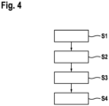
- 4 12 is a flowchart of a method for positioning the bearing cap to the housing in the vehicle electric axle device for the vehicle according to the first and second embodiments of the invention.
- the method includes providing S1 an electrical machine, power electronics for controlling the electrical machine, a transmission coupled to the electrical machine, and a housing in which at least the electrical machine and the transmission are accommodated.
- the method also includes positioning S2 of a plurality of bearings of the transmission to a bearing cap fastened to the transmission by means of a positioning device.
- the method also includes providing S3 the positioning device with first three-dimensional joining areas formed on a surface of the housing and second three-dimensional joining areas formed on an inside of the bearing cap.
- the method also includes a form-fitting joining S4 of the first three-dimensional joining areas of the housing and the second three-dimensional joining areas of the bearing cap.
- a shape, dimension, and/or a constitution of the components of the vehicle electric axle device 1 can be changed.
Landscapes
- Engineering & Computer Science (AREA)
- Power Engineering (AREA)
- Mechanical Engineering (AREA)
- General Engineering & Computer Science (AREA)
- Chemical & Material Sciences (AREA)
- Combustion & Propulsion (AREA)
- Transportation (AREA)
- General Details Of Gearings (AREA)
Description
- Die Erfindung betrifft eine elektrische Fahrzeugachsenvorrichtung für ein Kraftfahrzeug.
- Elektrische Fahrzeugachsenvorrichtungen für Kraftfahrzeuge weisen herkömmlicherweise eine elektrische Maschine, eine Leistungselektronik zum Ansteuern der elektrischen Maschine und ein mit der elektrischen Maschine gekoppeltes Getriebe auf.
- Ferner weist die elektrische Fahrzeugachsenvorrichtung ein Gehäuse auf, in welchem zumindest die elektrische Maschine und das Getriebe aufgenommen sind. Das Getriebe weist eine Mehrzahl von Lagern auf, welche durch eine Positioniereinrichtung zu einem an dem Gehäuse befestigten Lagerdeckel positioniert sind.
- Herkömmlicherweise ist die Positioniereinrichtung durch ein Paar von Passstiften bzw. Passbolzen ausgebildet, die in einem Randbereich des Gehäuses beliebig angeordnet sind und in senkrechtem Winkel vom Gehäuse abstehen. Der auf das Gehäuse aufzusetzende Deckel weist entsprechende Bohrungen auf, in welche die Passstifte bzw. Passbolzen des Gehäuses einfügbar sind.
- Eine solche Positioniereinrichtung kann jedoch keine genaue Positionierung bzw. Zentrierung der Lager bewirken, da gewisse axiale und/oder radiale Versätze entstehen können.
-
DE 10 2013 204 776 A1 offenbart eine elektrische Fahrzeugachsenvorrichtung, welche wenigstens eine Fahrzeugachse aufweist, an welcher Fahrzeugräder anbringbar sind, und wobei die elektrische Fahrzeugachsenvorrichtung ein Getriebe aufweist, welches mit der Fahrzeugachse verbunden ist. Ferner weist die Fahrzeugachsenvorrichtung einen Elektromotor auf, welcher mit dem Getriebe gekoppelt ist, zur Übertragung eines Drehmoments auf die Fahrzeugachse und die mit der Fahrzeugachse verbundenen Fahrzeugräder. Überdies weist die elektrische Fahrzeugachsenvorrichtung eine Leistungselektronik auf, wobei die Leistungselektronik einen Inverter aufweist, welcher mit dem Elektromotor verbunden ist, zum Speisen des Elektromotors mit elektrischer Energie. - Abseits von Fahrzeugachsenvorrichtungen kennt man mit Blick auf Stellantriebe in Kraftfahrzeugen die
DE 2015 226 755 A1 , welche einen Elektromotor mit einem Polgehäuse und einer mechanischen Schnittstelle zur zumindest mittelbaren Befestigung des Polgehäuses an einem Getriebegehäuse betrifft. Dort ist es vorgesehen, das Polgehäuse als gerolltes Polgehäuse auszubilden, und die mechanische Schnittstelle durch ein von dem Polgehäuse separates Bauteil in Form eines Lagerdeckels zu bilden, der mit dem Polgehäuse verbunden ist. - Weiterhin sind entsprechende Vorrichtungen bekannt aus der
US 2015/076972 A1 , derDE 10 2014 217 125 A1 , derEP 0 471 876 A1 und derJP 6 315 953 B2 - Es besteht somit ein Bedarf, eine elektrische Fahrzeugachsenvorrichtung vorzusehen, welche eine genauere Positionierung der Lager bzw. Achsen ermöglicht.
- Die vorliegende Erfindung schafft eine elektrische Fahrzeugachsenvorrichtung für ein Kraftfahrzeug, gemäß dem Gegenstand des unabhängigen Anspruchs 1. Weite mögliche Ausführungsformen der Erfindung bilden den Gegenstand der unabhängigen Ansprüche.
- Eine Idee der vorliegenden Erfindung ist es, durch Vorsehen der Positioniereinrichtung an der Oberfläche des Gehäuses in Form von ersten dreidimensionalen Fügebereichen und einer Innenseite des Lagerdeckels durch zweite dreidimensionale Fügebereiche, wobei die ersten dreidimensionalen Fügebereiche des Gehäuses an deren Boden und die zweiten dreidimensionalen Fügebereiche des Lagerdeckels formschlüssig zusammengefügt sind, eine verbesserte Positionierung bzw. Zentrierung der Lager zu ermöglichen, da die jeweiligen Fügebereiche des Gehäuses und des Lagerdeckels nunmehr Flächenkontakt bzw. Ringflächenkontakt gegenüber einem herkömmlichen Punkt- oder Linienkontakt aufweisen.
- Aufgrund des Deckel- und Topf-Sitzes, welcher aufgrund seiner Geometrie einen radialen Formschluss bildet und derart ausgebildet ist, dass dessen Mittelpunkt eine neue Achse bildet, die mit beispielsweise einer Motorachse bzw. einer Lagerachse am Deckel fluchtet kann so eine genauere achstreue Positionierung der Lager ermöglicht werden.
- Vorteilhafte Ausführungsformen und Weiterbildungen ergeben sich aus den Unteransprüchen sowie aus der Beschreibung unter Bezugnahme auf die Figuren.
- Die beschriebenen Ausgestaltungen und Weiterbildungen lassen sich beliebig miteinander kombinieren (im Rahmen der Erfindung, wie sie in den beigefügten Ansprüchen definiert ist).
- Weitere mögliche Ausgestaltungen, Weiterbildungen und Implementierungen der Erfindung umfassen auch nicht explizit genannte Kombinationen von zuvor oder im Folgenden bezüglich der Ausführungsbeispiele beschriebenen Merkmale der Erfindung. Die Erfindung ist nur durch den Umfang der beigefügten Ansprüche begrenzt.
- Die beiliegenden Zeichnungen sollen ein weiteres Verständnis der Ausführungsformen der Erfindung vermitteln. Sie veranschaulichen Ausführungsformen und dienen im Zusammenhang mit der Beschreibung der Erklärung von Prinzipien und Konzepten der Erfindung.
- Andere Ausführungsformen und viele der genannten Vorteile ergeben sich im Hinblick auf die Zeichnungen. Die dargestellten Elemente der Zeichnungen sind nicht notwendigerweise maßstabsgetreu zueinander gezeigt.
- Es zeigen:
- Fig. 1
- eine Seitenansicht einer elektrischen Fahrzeugachsenvorrichtung mit abgenommenem Lagerdeckel gemäß einer ersten Ausführungsform der Erfindung;
- Fig. 2
- eine Querschnittsansicht des an einem Gehäuse der elektrischen Fahrzeugachsenvorrichtung befestigten Lagerdeckels gemäß der ersten Ausführungsform der Erfindung;
- Fig. 3
- eine Querschnittsansicht des an einem Gehäuse der elektrischen Fahrzeugachsenvorrichtung befestigten Lagerdeckels gemäß einer zweiten Ausführungsform der Erfindung;
- Fig. 4
- ein Ablaufdiagramm eines Verfahrens zum Positionieren des Lagerdeckels zu dem Gehäuse in der elektrischen Fahrzeugachsenvorrichtung für das Kraftfahrzeug gemäß der ersten und zweiten Ausführungsform der Erfindung.
- In den Figuren der Zeichnungen bezeichnen gleiche Bezugszeichen gleiche oder funktionsgleiche Elemente, Bauteile oder Komponenten, soweit nichts Gegenteiliges angegeben ist.
-
Fig. 1 zeigt eine Seitenansicht einer elektrischen Fahrzeugachsenvorrichtung mit abgenommenem Lagerdeckel gemäß einer bevorzugten Ausführungsform der Erfindung. - Die elektrische Fahrzeugachsenvorrichtung 1 weist eine elektrische Maschine 10 auf. Ferner weist die elektrische Fahrzeugachsenvorrichtung 10 ein mit der elektrischen Maschine 10 gekoppeltes Getriebe 12 auf. Ferner weist die elektrische Fahrzeugachsenvorrichtung 1 ein Gehäuse 14 auf, in welchem zumindest die elektrische Maschine 10 und das Getriebe 12 aufgenommen sind. Das Getriebe 12 weist eine Mehrzahl von Lagern 16a, 16b auf.
- Die Mehrzahl von Lagern 16a, 16b sind durch eine Positioniereinrichtung 18 zu einem an dem Gehäuse 14 befestigten (in
Fig. 1 nicht gezeigten) Lagerdeckel positionierbar. Die Positioniereinrichtung 18 weist an einer Oberfläche 14a des Gehäuses 14 ausgebildete, erste dreidimensionale Fügebereiche 22a, 22b, 22c und an einer Innenseite des (inFig. 1 nicht gezeigten) Lagerdeckels ausgebildete, zweite dreidimensionale Fügebereiche auf. - Die ersten dreidimensionalen Fügebereiche 22a, 22b, 22c des Gehäuses 14 und die zweiten dreidimensionalen Fügebereiche des Lagerdeckels sind hierbei formschlüssig zusammenfügbar.
- An der Oberfläche 14a des Gehäuses 14 sind hierbei drei dreidimensionale Fügebereiche 22a, 22b, 22c und an der Innenseite des (in
Fig. 1 nicht dargestellten) Lagerdeckels ebenfalls drei zweite dreidimensionale Fügebereiche ausgebildet. Ferner sind die an der Oberfläche 14a des Gehäuses 14 ausgebildeten, ersten dreidimensionalen Fügebereiche 22a, 22b, 22c an einem Gehäuserand 30 und an einer zu der Mehrzahl von Lagern 16a, 16b benachbart angeordneten Gehäusewand 32 angeordnet. - Alternativ können die ersten dreidimensionalen Fügebereiche 22a, 22b, 22c beispielsweise lediglich im Bereich des Gehäuserands 30 oder lediglich bzw. ausschließlich im Bereich der Gehäusewand 32 angeordnet sein. Das Bezugszeichen 34 bezeichnet eine Antriebswelle der elektrischen Fahrzeugachsenvorrichtung 1.
-
Fig. 2 zeigt eine Querschnittsansicht des an einem Gehäuse der elektrischen Fahrzeugachsenvorrichtung befestigten Lagerdeckels gemäß einer ersten Ausführungsform der Erfindung. - Ein beispielhafter der an der Oberfläche 14a des Gehäuses 14 ausgebildeten ersten dreidimensionalen Fügebereiche 22a ist in der vorliegenden Ausführungsform konvex ausgebildet. Ein beispielhafter der an der Innenseite 20a des Lagerdeckels 20 ausgebildeten zweiten dreidimensionalen Fügebereiche 24a ist in der vorliegenden Ausführungsform konkav ausgebildet und mit dem ersten dreidimensionalen Fügebereich 22a des Gehäuses 14 formschlüssig zusammengefügt.
- Ferner ist vorgesehen, dass ein jeweiliger der, an der Oberfläche 14a des Gehäuses 14 ausgebildeten ersten konvex ausgebildeten dreidimensionalen Fügebereiche 22a einen kegeligen Vorsprung 26 aufweist. Ferner ist gemäß der vorliegenden Ausführungsform vorgesehen, dass der an der Innenseite 20a des Lagerdeckels 20 ausgebildete zweite dreidimensionale Fügebereich 24a eine kegelige Aussparung 28 aufweist.
-
Fig. 3 zeigt eine Querschnittsansicht des an einem Gehäuse der elektrischen Fahrzeugachsenvorrichtung befestigten Lagerdeckels gemäß einer zweiten Ausführungsform der Erfindung. - Erfindungsgemäß ist vorgesehen, dass die an der Oberfläche 14a des Gehäuses 14 ausgebildeten, ersten dreidimensionalen Fügebereiche 22a (von welchen in
Fig. 3 einer beispielhaft dargestellt ist) jeweils konkav ausgebildet sind. Ferner ist vorgesehen, dass die an der Innenseite 20a des Lagerdeckels 20 ausgebildeten, zweiten dreidimensionalen Fügebereiche 24a jeweils konvex ausgebildet und mit dem ersten dreidimensionalen Fügebereich 22a des Gehäuses 14 formschlüssig zusammengefügt sind. - Ferner ist vorgesehen, dass ein jeweiliger der, an der Innenseite 20a des Lagerdeckels 20 ausgebildeten ersten konvex ausgebildeten dreidimensionalen Fügebereiche 24a einen kegeligen Vorsprung 26a aufweist. Ferner ist gemäß der vorliegenden Ausführungsform vorgesehen, dass der an der Innenseite 20a des Lagerdeckels 20 ausgebildete zweite dreidimensionale Fügebereich 24a eine kegelige Aussparung 28a aufweist. Die jeweils konvex ausgebildeten zweiten dreidimensionalen Fügebereiche 24a des Lagerdeckels 20 weisen einen Radius R auf.
-
Fig. 4 zeigt ein Ablaufdiagramm eines Verfahrens zum Positionieren des Lagerdeckels zu dem Gehäuse in der elektrischen Fahrzeugachsenvorrichtung für das Kraftfahrzeug gemäß der ersten und zweiten Ausführungsform der Erfindung. - Das Verfahren umfasst ein Bereitstellen S1 einer elektrischen Maschine, einer Leistungselektronik zum Ansteuern der elektrischen Maschine, einem mit der elektrischen Maschine gekoppelten Getriebe und eines Gehäuses, in welchem zumindest die elektrische Maschine und das Getriebe aufgenommen sind.
- Das Verfahren umfasst ferner ein Positionieren S2 einer Mehrzahl von Lagern des Getriebes zu einem an dem Getriebe befestigten Lagerdeckel mittels einer Positioniereinrichtung.
- Das Verfahren umfasst überdies ein Bereitstellen S3 der Positioniereinrichtung mit an einer Oberfläche des Gehäuses ausgebildeten, ersten dreidimensionalen Fügebereichen und an einer Innenseite des Lagerdeckels ausgebildeten, zweiten dreidimensionalen Fügebereichen.
- Das Verfahren umfasst überdies ein formschlüssiges Zusammenfügen S4 der ersten dreidimensionalen Fügebereiche des Gehäuses und der zweiten dreidimensionalen Fügebereiche des Lagerdeckels.
- Obwohl die vorliegende Erfindung anhand bevorzugter Ausführungsbeispiele vorstehend beschrieben wurde, ist sie nicht darauf beschränkt, sondern auf vielfältige Art und Weise modifizierbar (innerhalb des durch die beigefügten Ansprüche definierten Schutzbereichs).
- Beispielsweise können eine Form, Abmessung und/oder eine Beschaffenheit der Komponenten der elektrischen Fahrzeugachsenvorrichtung 1 abgeändert werden.
Claims (6)
- Elektrische Fahrzeugachsenvorrichtung (1) für ein Kraftfahrzeug, mit einer elektrischen Maschine (10), mit einem mit der elektrischen Maschine (10) gekoppelten Getriebe (12) und mit einem Gehäuse (14), in welchem zumindest die elektrische Maschine (10) und das Getriebe (12) aufgenommen sind, wobei das Getriebe (12) eine Mehrzahl von Lagern (16a, 16b) aufweist, welche durch eine Positioniereinrichtung (18) zu einem an dem Gehäuse (14) befestigten Lagerdeckel (20) positioniert sind, wobei die Positioniereinrichtung (18) an einer Oberfläche (14a) des Gehäuses (14) ausgebildete, erste dreidimensionale Fügebereiche (22a, 22b, 22c) und an einer Innenseite (20a) des Lagerdeckels (20) ausgebildete, zweite dreidimensionale Fügebereiche (24a, 24b, 24c) aufweist, wobei die ersten dreidimensionalen Fügebereiche (22a, 22b, 22c) des Gehäuses (14) und die zweiten dreidimensionalen Fügebereiche (24a, 24b, 24c) des Lagerdeckels (20) formschlüssig zusammengefügt sind, dadurch gekennzeichnet, dass entweder die an der Oberfläche (14a) des Gehäuses (14) ausgebildeten, ersten dreidimensionalen Fügebereiche (22a, 22b, 22c) jeweils konvex ausgebildet sind und die an der Innenseite (20a) des Lagerdeckels (20) ausgebildeten, zweiten dreidimensionalen Fügebereiche (24a, 24b, 24c) jeweils konkav ausgebildet sind und ein jeweiliger der, an der Oberfläche (14a) des Gehäuses (14) ausgebildeten, ersten konvex ausgebildeten dreidimensionalen Fügebereiche (22a, 22b, 22c) einen kegeligen Vorsprung (26) aufweist; oder dass die an der Oberfläche (14a) des Gehäuses (14) ausgebildeten, ersten dreidimensionalen Fügebereiche (22a, 22b, 22c) jeweils konkav ausgebildet sind und die an der Innenseite (20a) des Lagerdeckels (20) ausgebildeten, zweiten dreidimensionalen Fügebereiche (24a, 24b, 24c) jeweils konvex ausgebildet sind und ein jeweiliger der, an der Oberfläche (14a) des Gehäuses (14) ausgebildeten, ersten konkav ausgebildeten dreidimensionalen Fügebereiche (22a, 22b, 22c) eine kegelige Aussparung (28) aufweist..
- Elektrische Fahrzeugachsenvorrichtung nach Anspruch 1, dadurch gekennzeichnet, dass zumindest einer der an der Oberfläche (14a) des Gehäuses (14) ausgebildeten ersten dreidimensionalen Fügebereiche (22a, 22b, 22c) konvex und zumindest ein weiterer der an der Oberfläche (14a) des Gehäuses (14) ausgebildeten ersten dreidimensionalen Fügebereiche (22a, 22b, 22c) konkav ausgebildet ist.
- Elektrische Fahrzeugachsenvorrichtung nach Anspruch 2, dadurch gekennzeichnet, dass zumindest einer der an der Innenseite (20a) des Lagerdeckels (20) ausgebildeten zweiten dreidimensionalen Fügebereiche (24a, 24b, 24c) konvex und zumindest ein weiterer der an der Innenseite (20a) des Lagerdeckels (20) ausgebildeten zweiten dreidimensionalen Fügebereiche (24a, 24b, 24c) konkav ausgebildet ist.
- Elektrische Fahrzeugachsenvorrichtung nach einem der vorhergehenden Ansprüche, dadurch gekennzeichnet, dass an der Oberfläche (14a) des Gehäuses (14) drei erste dreidimensionale Fügebereiche (22a, 22b, 22c) und an der Innenseite (20a) des Lagerdeckels (20) drei zweite dreidimensionale Fügebereiche (24a, 24b, 24c) ausgebildet sind.
- Elektrische Fahrzeugachsenvorrichtung nach einem der Ansprüche 2 bis 4, dadurch gekennzeichnet, dass ein jeweiliger der an der Innenseite (20a) des Lagerdeckels (20) ausgebildeten, zweiten konvex ausgebildeten dreidimensionalen Fügebereiche (24a, 24b, 24c) einen kegeligen Vorsprung (26) aufweist und/oder ein jeweiliger der, an der Innenseite (20a) des Lagerdeckels (20) ausgebildeten, zweiten konkav ausgebildeten dreidimensionalen Fügebereiche (24a, 24b, 24c) eine kegelige Aussparung (28) aufweist.
- Elektrische Fahrzeugachsenvorrichtung nach einem der vorhergehenden Ansprüche, dadurch gekennzeichnet, dass die an der Oberfläche (14a) des Gehäuses (14) ausgebildeten, ersten dreidimensionalen Fügebereiche (22a, 22b, 22c) an einem Gehäuserand (30) und/oder einer zu der Mehrzahl von Lagern (16a, 16b) benachbart angeordneten Gehäusewand (32) angeordnet sind.
Applications Claiming Priority (1)
| Application Number | Priority Date | Filing Date | Title |
|---|---|---|---|
| DE102018211938.4A DE102018211938A1 (de) | 2018-07-18 | 2018-07-18 | Elektrische Fahrzeugachsenvorrichtung und Verfahren zum Positionieren eines Lagerdeckels zu einem Gehäuse in einer elektrischen Fahrzeugachsenvorrichtung |
Publications (2)
| Publication Number | Publication Date |
|---|---|
| EP3597462A1 EP3597462A1 (de) | 2020-01-22 |
| EP3597462B1 true EP3597462B1 (de) | 2023-04-19 |
Family
ID=67314670
Family Applications (1)
| Application Number | Title | Priority Date | Filing Date |
|---|---|---|---|
| EP19186546.8A Active EP3597462B1 (de) | 2018-07-18 | 2019-07-16 | Elektrische fahrzeugachsenvorrichtung |
Country Status (2)
| Country | Link |
|---|---|
| EP (1) | EP3597462B1 (de) |
| DE (1) | DE102018211938A1 (de) |
Families Citing this family (1)
| Publication number | Priority date | Publication date | Assignee | Title |
|---|---|---|---|---|
| EP4246016A1 (de) | 2022-03-16 | 2023-09-20 | Valeo eAutomotive Germany GmbH | Getriebe mit verbesserter ausrichtung von gehäuseteilen |
Citations (1)
| Publication number | Priority date | Publication date | Assignee | Title |
|---|---|---|---|---|
| DE19816699A1 (de) * | 1997-04-17 | 1998-10-22 | Aisin Aw Co | Antriebssystem für Elektrofahrzeuge |
Family Cites Families (6)
| Publication number | Priority date | Publication date | Assignee | Title |
|---|---|---|---|---|
| DE59006072D1 (de) * | 1990-08-23 | 1994-07-14 | Siemens Ag | Motor-Getriebe-Antriebseinheit, insbesondere Kraftfahrzeug-Fensterheberantrieb. |
| US10250098B2 (en) * | 2012-04-20 | 2019-04-02 | Ipgate Ag | Bearing arrangement in an axial drive with dual stators and one rotor |
| JP6315953B2 (ja) * | 2013-01-18 | 2018-04-25 | 株式会社ミツバ | 電動モータ及び電動ポンプ |
| DE102013204776A1 (de) | 2013-03-19 | 2014-09-25 | Zf Friedrichshafen Ag | Getriebe für ein Kraftfahrzeug |
| DE102014217125A1 (de) * | 2014-08-28 | 2016-03-03 | Robert Bosch Gmbh | Startvorrichtung für eine Brennkraftmaschine |
| DE102015226755A1 (de) * | 2015-12-28 | 2017-06-29 | Robert Bosch Gmbh | Elektromotor für Stellantriebe in Kraftfahrzeugen und Getriebe-Antriebseinrichtung |
-
2018
- 2018-07-18 DE DE102018211938.4A patent/DE102018211938A1/de not_active Withdrawn
-
2019
- 2019-07-16 EP EP19186546.8A patent/EP3597462B1/de active Active
Patent Citations (1)
| Publication number | Priority date | Publication date | Assignee | Title |
|---|---|---|---|---|
| DE19816699A1 (de) * | 1997-04-17 | 1998-10-22 | Aisin Aw Co | Antriebssystem für Elektrofahrzeuge |
Also Published As
| Publication number | Publication date |
|---|---|
| DE102018211938A1 (de) | 2020-01-23 |
| EP3597462A1 (de) | 2020-01-22 |
Similar Documents
| Publication | Publication Date | Title |
|---|---|---|
| DE102011050094A1 (de) | Rotor für eine drehende elektrische Maschine | |
| DE102016205115A1 (de) | Getriebevorrichtung | |
| DE102015113509A1 (de) | Freitragender Stator | |
| DE102017011969A1 (de) | Verfahren zum Herstellen einer Rotoreinheit für einen Elektromotor | |
| DE212019000232U1 (de) | Integrierte Leistungsquelle und Gehäuse | |
| DE10059684B4 (de) | Differenzialgetriebe für Kraftfahrzeuge | |
| DE102017122908A1 (de) | Segmentierter geschalteter Reluktanzmotor für die Kraftstrangelektrifizierung | |
| DE102014115196A1 (de) | System und Verfahren zur zusammengefassten Drehmomentübertragung und Rotationsdichtung | |
| EP3597462A1 (de) | Elektrische fahrzeugachsenvorrichtung und verfahren zum positionieren eines lagerdeckels zu einem gehäuse in einer elektrischen fahrzeugachsenvorrichtung | |
| EP4071384B1 (de) | Hybrid-getriebevorrichtung | |
| EP4620089A1 (de) | Maschinengehäuse für eine maschinenanordnung, verfahren zur herstellung einer maschinenanordnung und maschinenanordnung für ein kraftfahrzeug | |
| DE102012007725A1 (de) | Verfahren zum Herstellen einer Kurbelwelle | |
| WO2017097520A1 (de) | Magnetsegment für einen rotor, rotor sowie verfahren zum herstellen eines rotors | |
| DE102021126459A1 (de) | Gehäuse für einen elektrischen Antrieb eines Kraftfahrzeugs, Kraftfahrzeug sowie Verfahren | |
| EP1035349A2 (de) | Gummilager mit Axialanschlägen und Verfahren zur Herstellung eines Gummilagers mit integrierten Axialanschlägen | |
| DE102022214153A1 (de) | Elektrische Antriebsvorrichtung für ein Fahrzeug und Verfahren zum Herstellen einer elektrischen Antriebsvorrichtung für ein Fahrzeug | |
| WO2020064272A1 (de) | Läuferrohr für eine elektrische maschine eines fahrzeugs | |
| DE102023204104A1 (de) | Elektrische Antriebsvorrichtung für ein Fahrzeug und Verfahren zum Herstellen einer elektrischen Antriebsvorrichtung für ein Fahrzeug | |
| DE102014018745A1 (de) | Elektrische Maschine, insbesondere für einen Kraftwagen, sowie Verfahren zum Herstellen einer solchen elektrischen Maschine | |
| DE102023115445A1 (de) | Planetenradträger, Verfahren zur Herstellung eines Planetenradträgers, Planetengetriebe und Achsantriebsstrang | |
| DE102018204637A1 (de) | Rotor einer elektrischen Maschine in Modulbauweise | |
| EP4686852A1 (de) | Lageranordnung mit elektrisch isolierendem isolationsteil | |
| DE102022212847A1 (de) | Verfahren zum Fügen eines Einlegeteils mit einem umformbaren Material | |
| DE102023004703A1 (de) | Radnabenantrieb für ein Kraftfahrzeug sowie Kraftfahrzeug | |
| DE102024203590A1 (de) | Verfahren zur Herstellung einer Radanordnung |
Legal Events
| Date | Code | Title | Description |
|---|---|---|---|
| PUAI | Public reference made under article 153(3) epc to a published international application that has entered the european phase |
Free format text: ORIGINAL CODE: 0009012 |
|
| STAA | Information on the status of an ep patent application or granted ep patent |
Free format text: STATUS: THE APPLICATION HAS BEEN PUBLISHED |
|
| AK | Designated contracting states |
Kind code of ref document: A1 Designated state(s): AL AT BE BG CH CY CZ DE DK EE ES FI FR GB GR HR HU IE IS IT LI LT LU LV MC MK MT NL NO PL PT RO RS SE SI SK SM TR |
|
| AX | Request for extension of the european patent |
Extension state: BA ME |
|
| RAP1 | Party data changed (applicant data changed or rights of an application transferred) |
Owner name: ROBERT BOSCH GMBH |
|
| STAA | Information on the status of an ep patent application or granted ep patent |
Free format text: STATUS: REQUEST FOR EXAMINATION WAS MADE |
|
| 17P | Request for examination filed |
Effective date: 20200722 |
|
| RBV | Designated contracting states (corrected) |
Designated state(s): AL AT BE BG CH CY CZ DE DK EE ES FI FR GB GR HR HU IE IS IT LI LT LU LV MC MK MT NL NO PL PT RO RS SE SI SK SM TR |
|
| STAA | Information on the status of an ep patent application or granted ep patent |
Free format text: STATUS: EXAMINATION IS IN PROGRESS |
|
| 17Q | First examination report despatched |
Effective date: 20210121 |
|
| RIC1 | Information provided on ipc code assigned before grant |
Ipc: H02K 7/116 20060101ALN20221121BHEP Ipc: F16C 35/00 20060101ALN20221121BHEP Ipc: H02K 5/15 20060101ALN20221121BHEP Ipc: F16C 35/04 20060101ALN20221121BHEP Ipc: H02K 5/16 20060101ALN20221121BHEP Ipc: B60K 1/00 20060101AFI20221121BHEP |
|
| RIC1 | Information provided on ipc code assigned before grant |
Ipc: H02K 7/116 20060101ALN20221125BHEP Ipc: F16C 35/00 20060101ALN20221125BHEP Ipc: H02K 5/15 20060101ALN20221125BHEP Ipc: F16C 35/04 20060101ALN20221125BHEP Ipc: H02K 5/16 20060101ALN20221125BHEP Ipc: B60K 1/00 20060101AFI20221125BHEP |
|
| GRAP | Despatch of communication of intention to grant a patent |
Free format text: ORIGINAL CODE: EPIDOSNIGR1 |
|
| STAA | Information on the status of an ep patent application or granted ep patent |
Free format text: STATUS: GRANT OF PATENT IS INTENDED |
|
| INTG | Intention to grant announced |
Effective date: 20230113 |
|
| GRAS | Grant fee paid |
Free format text: ORIGINAL CODE: EPIDOSNIGR3 |
|
| GRAA | (expected) grant |
Free format text: ORIGINAL CODE: 0009210 |
|
| STAA | Information on the status of an ep patent application or granted ep patent |
Free format text: STATUS: THE PATENT HAS BEEN GRANTED |
|
| REG | Reference to a national code |
Ref country code: DE Ref legal event code: R081 Ref document number: 502019007475 Country of ref document: DE Owner name: ROBERT BOSCH GESELLSCHAFT MIT BESCHRAENKTER HA, DE Free format text: FORMER OWNER: ROBERT BOSCH GMBH, 70469 STUTTGART, DE |
|
| AK | Designated contracting states |
Kind code of ref document: B1 Designated state(s): AL AT BE BG CH CY CZ DE DK EE ES FI FR GB GR HR HU IE IS IT LI LT LU LV MC MK MT NL NO PL PT RO RS SE SI SK SM TR |
|
| REG | Reference to a national code |
Ref country code: GB Ref legal event code: FG4D Free format text: NOT ENGLISH |
|
| REG | Reference to a national code |
Ref country code: CH Ref legal event code: EP |
|
| REG | Reference to a national code |
Ref country code: DE Ref legal event code: R096 Ref document number: 502019007475 Country of ref document: DE |
|
| REG | Reference to a national code |
Ref country code: IE Ref legal event code: FG4D Free format text: LANGUAGE OF EP DOCUMENT: GERMAN |
|
| REG | Reference to a national code |
Ref country code: AT Ref legal event code: REF Ref document number: 1560938 Country of ref document: AT Kind code of ref document: T Effective date: 20230515 |
|
| REG | Reference to a national code |
Ref country code: LT Ref legal event code: MG9D |
|
| REG | Reference to a national code |
Ref country code: NL Ref legal event code: MP Effective date: 20230419 |
|
| PG25 | Lapsed in a contracting state [announced via postgrant information from national office to epo] |
Ref country code: NL Free format text: LAPSE BECAUSE OF FAILURE TO SUBMIT A TRANSLATION OF THE DESCRIPTION OR TO PAY THE FEE WITHIN THE PRESCRIBED TIME-LIMIT Effective date: 20230419 |
|
| PG25 | Lapsed in a contracting state [announced via postgrant information from national office to epo] |
Ref country code: SE Free format text: LAPSE BECAUSE OF FAILURE TO SUBMIT A TRANSLATION OF THE DESCRIPTION OR TO PAY THE FEE WITHIN THE PRESCRIBED TIME-LIMIT Effective date: 20230419 Ref country code: PT Free format text: LAPSE BECAUSE OF FAILURE TO SUBMIT A TRANSLATION OF THE DESCRIPTION OR TO PAY THE FEE WITHIN THE PRESCRIBED TIME-LIMIT Effective date: 20230821 Ref country code: NO Free format text: LAPSE BECAUSE OF FAILURE TO SUBMIT A TRANSLATION OF THE DESCRIPTION OR TO PAY THE FEE WITHIN THE PRESCRIBED TIME-LIMIT Effective date: 20230719 Ref country code: ES Free format text: LAPSE BECAUSE OF FAILURE TO SUBMIT A TRANSLATION OF THE DESCRIPTION OR TO PAY THE FEE WITHIN THE PRESCRIBED TIME-LIMIT Effective date: 20230419 |
|
| PG25 | Lapsed in a contracting state [announced via postgrant information from national office to epo] |
Ref country code: RS Free format text: LAPSE BECAUSE OF FAILURE TO SUBMIT A TRANSLATION OF THE DESCRIPTION OR TO PAY THE FEE WITHIN THE PRESCRIBED TIME-LIMIT Effective date: 20230419 Ref country code: PL Free format text: LAPSE BECAUSE OF FAILURE TO SUBMIT A TRANSLATION OF THE DESCRIPTION OR TO PAY THE FEE WITHIN THE PRESCRIBED TIME-LIMIT Effective date: 20230419 Ref country code: LV Free format text: LAPSE BECAUSE OF FAILURE TO SUBMIT A TRANSLATION OF THE DESCRIPTION OR TO PAY THE FEE WITHIN THE PRESCRIBED TIME-LIMIT Effective date: 20230419 Ref country code: LT Free format text: LAPSE BECAUSE OF FAILURE TO SUBMIT A TRANSLATION OF THE DESCRIPTION OR TO PAY THE FEE WITHIN THE PRESCRIBED TIME-LIMIT Effective date: 20230419 Ref country code: IS Free format text: LAPSE BECAUSE OF FAILURE TO SUBMIT A TRANSLATION OF THE DESCRIPTION OR TO PAY THE FEE WITHIN THE PRESCRIBED TIME-LIMIT Effective date: 20230819 Ref country code: HR Free format text: LAPSE BECAUSE OF FAILURE TO SUBMIT A TRANSLATION OF THE DESCRIPTION OR TO PAY THE FEE WITHIN THE PRESCRIBED TIME-LIMIT Effective date: 20230419 Ref country code: GR Free format text: LAPSE BECAUSE OF FAILURE TO SUBMIT A TRANSLATION OF THE DESCRIPTION OR TO PAY THE FEE WITHIN THE PRESCRIBED TIME-LIMIT Effective date: 20230720 Ref country code: AL Free format text: LAPSE BECAUSE OF FAILURE TO SUBMIT A TRANSLATION OF THE DESCRIPTION OR TO PAY THE FEE WITHIN THE PRESCRIBED TIME-LIMIT Effective date: 20230419 |
|
| PG25 | Lapsed in a contracting state [announced via postgrant information from national office to epo] |
Ref country code: FI Free format text: LAPSE BECAUSE OF FAILURE TO SUBMIT A TRANSLATION OF THE DESCRIPTION OR TO PAY THE FEE WITHIN THE PRESCRIBED TIME-LIMIT Effective date: 20230419 |
|
| PG25 | Lapsed in a contracting state [announced via postgrant information from national office to epo] |
Ref country code: SK Free format text: LAPSE BECAUSE OF FAILURE TO SUBMIT A TRANSLATION OF THE DESCRIPTION OR TO PAY THE FEE WITHIN THE PRESCRIBED TIME-LIMIT Effective date: 20230419 |
|
| REG | Reference to a national code |
Ref country code: DE Ref legal event code: R097 Ref document number: 502019007475 Country of ref document: DE |
|
| PG25 | Lapsed in a contracting state [announced via postgrant information from national office to epo] |
Ref country code: SM Free format text: LAPSE BECAUSE OF FAILURE TO SUBMIT A TRANSLATION OF THE DESCRIPTION OR TO PAY THE FEE WITHIN THE PRESCRIBED TIME-LIMIT Effective date: 20230419 Ref country code: SK Free format text: LAPSE BECAUSE OF FAILURE TO SUBMIT A TRANSLATION OF THE DESCRIPTION OR TO PAY THE FEE WITHIN THE PRESCRIBED TIME-LIMIT Effective date: 20230419 Ref country code: RO Free format text: LAPSE BECAUSE OF FAILURE TO SUBMIT A TRANSLATION OF THE DESCRIPTION OR TO PAY THE FEE WITHIN THE PRESCRIBED TIME-LIMIT Effective date: 20230419 Ref country code: EE Free format text: LAPSE BECAUSE OF FAILURE TO SUBMIT A TRANSLATION OF THE DESCRIPTION OR TO PAY THE FEE WITHIN THE PRESCRIBED TIME-LIMIT Effective date: 20230419 Ref country code: DK Free format text: LAPSE BECAUSE OF FAILURE TO SUBMIT A TRANSLATION OF THE DESCRIPTION OR TO PAY THE FEE WITHIN THE PRESCRIBED TIME-LIMIT Effective date: 20230419 Ref country code: CZ Free format text: LAPSE BECAUSE OF FAILURE TO SUBMIT A TRANSLATION OF THE DESCRIPTION OR TO PAY THE FEE WITHIN THE PRESCRIBED TIME-LIMIT Effective date: 20230419 |
|
| PLBE | No opposition filed within time limit |
Free format text: ORIGINAL CODE: 0009261 |
|
| STAA | Information on the status of an ep patent application or granted ep patent |
Free format text: STATUS: NO OPPOSITION FILED WITHIN TIME LIMIT |
|
| PG25 | Lapsed in a contracting state [announced via postgrant information from national office to epo] |
Ref country code: MC Free format text: LAPSE BECAUSE OF FAILURE TO SUBMIT A TRANSLATION OF THE DESCRIPTION OR TO PAY THE FEE WITHIN THE PRESCRIBED TIME-LIMIT Effective date: 20230419 |
|
| PG25 | Lapsed in a contracting state [announced via postgrant information from national office to epo] |
Ref country code: MC Free format text: LAPSE BECAUSE OF FAILURE TO SUBMIT A TRANSLATION OF THE DESCRIPTION OR TO PAY THE FEE WITHIN THE PRESCRIBED TIME-LIMIT Effective date: 20230419 |
|
| REG | Reference to a national code |
Ref country code: CH Ref legal event code: PL |
|
| REG | Reference to a national code |
Ref country code: BE Ref legal event code: MM Effective date: 20230731 |
|
| PG25 | Lapsed in a contracting state [announced via postgrant information from national office to epo] |
Ref country code: LU Free format text: LAPSE BECAUSE OF NON-PAYMENT OF DUE FEES Effective date: 20230716 |
|
| 26N | No opposition filed |
Effective date: 20240122 |
|
| GBPC | Gb: european patent ceased through non-payment of renewal fee |
Effective date: 20230719 |
|
| PG25 | Lapsed in a contracting state [announced via postgrant information from national office to epo] |
Ref country code: LU Free format text: LAPSE BECAUSE OF NON-PAYMENT OF DUE FEES Effective date: 20230716 |
|
| REG | Reference to a national code |
Ref country code: IE Ref legal event code: MM4A |
|
| PG25 | Lapsed in a contracting state [announced via postgrant information from national office to epo] |
Ref country code: CH Free format text: LAPSE BECAUSE OF NON-PAYMENT OF DUE FEES Effective date: 20230731 Ref country code: GB Free format text: LAPSE BECAUSE OF NON-PAYMENT OF DUE FEES Effective date: 20230719 |
|
| PG25 | Lapsed in a contracting state [announced via postgrant information from national office to epo] |
Ref country code: SI Free format text: LAPSE BECAUSE OF FAILURE TO SUBMIT A TRANSLATION OF THE DESCRIPTION OR TO PAY THE FEE WITHIN THE PRESCRIBED TIME-LIMIT Effective date: 20230419 |
|
| PG25 | Lapsed in a contracting state [announced via postgrant information from national office to epo] |
Ref country code: SI Free format text: LAPSE BECAUSE OF FAILURE TO SUBMIT A TRANSLATION OF THE DESCRIPTION OR TO PAY THE FEE WITHIN THE PRESCRIBED TIME-LIMIT Effective date: 20230419 Ref country code: IT Free format text: LAPSE BECAUSE OF FAILURE TO SUBMIT A TRANSLATION OF THE DESCRIPTION OR TO PAY THE FEE WITHIN THE PRESCRIBED TIME-LIMIT Effective date: 20230419 Ref country code: FR Free format text: LAPSE BECAUSE OF NON-PAYMENT OF DUE FEES Effective date: 20230731 Ref country code: BE Free format text: LAPSE BECAUSE OF NON-PAYMENT OF DUE FEES Effective date: 20230731 |
|
| PG25 | Lapsed in a contracting state [announced via postgrant information from national office to epo] |
Ref country code: IE Free format text: LAPSE BECAUSE OF NON-PAYMENT OF DUE FEES Effective date: 20230716 |
|
| PG25 | Lapsed in a contracting state [announced via postgrant information from national office to epo] |
Ref country code: IE Free format text: LAPSE BECAUSE OF NON-PAYMENT OF DUE FEES Effective date: 20230716 |
|
| PG25 | Lapsed in a contracting state [announced via postgrant information from national office to epo] |
Ref country code: BG Free format text: LAPSE BECAUSE OF FAILURE TO SUBMIT A TRANSLATION OF THE DESCRIPTION OR TO PAY THE FEE WITHIN THE PRESCRIBED TIME-LIMIT Effective date: 20230419 |
|
| PG25 | Lapsed in a contracting state [announced via postgrant information from national office to epo] |
Ref country code: BG Free format text: LAPSE BECAUSE OF FAILURE TO SUBMIT A TRANSLATION OF THE DESCRIPTION OR TO PAY THE FEE WITHIN THE PRESCRIBED TIME-LIMIT Effective date: 20230419 |
|
| PG25 | Lapsed in a contracting state [announced via postgrant information from national office to epo] |
Ref country code: CY Free format text: LAPSE BECAUSE OF FAILURE TO SUBMIT A TRANSLATION OF THE DESCRIPTION OR TO PAY THE FEE WITHIN THE PRESCRIBED TIME-LIMIT; INVALID AB INITIO Effective date: 20190716 |
|
| PG25 | Lapsed in a contracting state [announced via postgrant information from national office to epo] |
Ref country code: HU Free format text: LAPSE BECAUSE OF FAILURE TO SUBMIT A TRANSLATION OF THE DESCRIPTION OR TO PAY THE FEE WITHIN THE PRESCRIBED TIME-LIMIT; INVALID AB INITIO Effective date: 20190716 |
|
| REG | Reference to a national code |
Ref country code: AT Ref legal event code: MM01 Ref document number: 1560938 Country of ref document: AT Kind code of ref document: T Effective date: 20240716 |
|
| PGFP | Annual fee paid to national office [announced via postgrant information from national office to epo] |
Ref country code: DE Payment date: 20250924 Year of fee payment: 7 |
|
| PG25 | Lapsed in a contracting state [announced via postgrant information from national office to epo] |
Ref country code: AT Free format text: LAPSE BECAUSE OF NON-PAYMENT OF DUE FEES Effective date: 20240716 |
|
| PG25 | Lapsed in a contracting state [announced via postgrant information from national office to epo] |
Ref country code: TR Free format text: LAPSE BECAUSE OF FAILURE TO SUBMIT A TRANSLATION OF THE DESCRIPTION OR TO PAY THE FEE WITHIN THE PRESCRIBED TIME-LIMIT Effective date: 20230419 |
|
| PGFP | Annual fee paid to national office [announced via postgrant information from national office to epo] |
Ref country code: AT Payment date: 20260410 Year of fee payment: 5 |