EP3597342B1 - Manufacturing method, manufacturing system, and manufacturing program for additive manufactured object - Google Patents
Manufacturing method, manufacturing system, and manufacturing program for additive manufactured object Download PDFInfo
- Publication number
- EP3597342B1 EP3597342B1 EP18768083.0A EP18768083A EP3597342B1 EP 3597342 B1 EP3597342 B1 EP 3597342B1 EP 18768083 A EP18768083 A EP 18768083A EP 3597342 B1 EP3597342 B1 EP 3597342B1
- Authority
- EP
- European Patent Office
- Prior art keywords
- melt bead
- height
- melt
- bead
- layer
- Prior art date
- Legal status (The legal status is an assumption and is not a legal conclusion. Google has not performed a legal analysis and makes no representation as to the accuracy of the status listed.)
- Active
Links
- 238000004519 manufacturing process Methods 0.000 title claims description 22
- 239000000654 additive Substances 0.000 title 1
- 230000000996 additive effect Effects 0.000 title 1
- 239000011324 bead Substances 0.000 claims description 153
- 239000000155 melt Substances 0.000 claims description 114
- 238000003466 welding Methods 0.000 claims description 47
- 238000000034 method Methods 0.000 claims description 30
- 238000005520 cutting process Methods 0.000 claims description 26
- 238000010030 laminating Methods 0.000 claims description 22
- 230000015572 biosynthetic process Effects 0.000 claims description 6
- 238000003475 lamination Methods 0.000 description 21
- 239000002184 metal Substances 0.000 description 14
- 229910052751 metal Inorganic materials 0.000 description 14
- 239000000945 filler Substances 0.000 description 10
- 239000000463 material Substances 0.000 description 10
- 238000000465 moulding Methods 0.000 description 7
- 238000012937 correction Methods 0.000 description 3
- 238000002844 melting Methods 0.000 description 3
- 230000008018 melting Effects 0.000 description 3
- 238000012545 processing Methods 0.000 description 3
- 230000002411 adverse Effects 0.000 description 2
- 239000007769 metal material Substances 0.000 description 2
- 230000001419 dependent effect Effects 0.000 description 1
- 230000000694 effects Effects 0.000 description 1
- 238000010894 electron beam technology Methods 0.000 description 1
- 238000003384 imaging method Methods 0.000 description 1
- 238000003754 machining Methods 0.000 description 1
- 238000005259 measurement Methods 0.000 description 1
- 238000001465 metallisation Methods 0.000 description 1
- 150000002739 metals Chemical class 0.000 description 1
- 238000012986 modification Methods 0.000 description 1
- 230000004048 modification Effects 0.000 description 1
- 239000000843 powder Substances 0.000 description 1
- 238000000275 quality assurance Methods 0.000 description 1
Images


Classifications
-
- B—PERFORMING OPERATIONS; TRANSPORTING
- B23—MACHINE TOOLS; METAL-WORKING NOT OTHERWISE PROVIDED FOR
- B23K—SOLDERING OR UNSOLDERING; WELDING; CLADDING OR PLATING BY SOLDERING OR WELDING; CUTTING BY APPLYING HEAT LOCALLY, e.g. FLAME CUTTING; WORKING BY LASER BEAM
- B23K9/00—Arc welding or cutting
- B23K9/02—Seam welding; Backing means; Inserts
- B23K9/032—Seam welding; Backing means; Inserts for three-dimensional seams
-
- B—PERFORMING OPERATIONS; TRANSPORTING
- B22—CASTING; POWDER METALLURGY
- B22F—WORKING METALLIC POWDER; MANUFACTURE OF ARTICLES FROM METALLIC POWDER; MAKING METALLIC POWDER; APPARATUS OR DEVICES SPECIALLY ADAPTED FOR METALLIC POWDER
- B22F10/00—Additive manufacturing of workpieces or articles from metallic powder
- B22F10/50—Treatment of workpieces or articles during build-up, e.g. treatments applied to fused layers during build-up
-
- B—PERFORMING OPERATIONS; TRANSPORTING
- B33—ADDITIVE MANUFACTURING TECHNOLOGY
- B33Y—ADDITIVE MANUFACTURING, i.e. MANUFACTURING OF THREE-DIMENSIONAL [3-D] OBJECTS BY ADDITIVE DEPOSITION, ADDITIVE AGGLOMERATION OR ADDITIVE LAYERING, e.g. BY 3-D PRINTING, STEREOLITHOGRAPHY OR SELECTIVE LASER SINTERING
- B33Y10/00—Processes of additive manufacturing
-
- B—PERFORMING OPERATIONS; TRANSPORTING
- B33—ADDITIVE MANUFACTURING TECHNOLOGY
- B33Y—ADDITIVE MANUFACTURING, i.e. MANUFACTURING OF THREE-DIMENSIONAL [3-D] OBJECTS BY ADDITIVE DEPOSITION, ADDITIVE AGGLOMERATION OR ADDITIVE LAYERING, e.g. BY 3-D PRINTING, STEREOLITHOGRAPHY OR SELECTIVE LASER SINTERING
- B33Y30/00—Apparatus for additive manufacturing; Details thereof or accessories therefor
-
- B—PERFORMING OPERATIONS; TRANSPORTING
- B33—ADDITIVE MANUFACTURING TECHNOLOGY
- B33Y—ADDITIVE MANUFACTURING, i.e. MANUFACTURING OF THREE-DIMENSIONAL [3-D] OBJECTS BY ADDITIVE DEPOSITION, ADDITIVE AGGLOMERATION OR ADDITIVE LAYERING, e.g. BY 3-D PRINTING, STEREOLITHOGRAPHY OR SELECTIVE LASER SINTERING
- B33Y50/00—Data acquisition or data processing for additive manufacturing
- B33Y50/02—Data acquisition or data processing for additive manufacturing for controlling or regulating additive manufacturing processes
-
- B—PERFORMING OPERATIONS; TRANSPORTING
- B22—CASTING; POWDER METALLURGY
- B22F—WORKING METALLIC POWDER; MANUFACTURE OF ARTICLES FROM METALLIC POWDER; MAKING METALLIC POWDER; APPARATUS OR DEVICES SPECIALLY ADAPTED FOR METALLIC POWDER
- B22F10/00—Additive manufacturing of workpieces or articles from metallic powder
- B22F10/20—Direct sintering or melting
- B22F10/25—Direct deposition of metal particles, e.g. direct metal deposition [DMD] or laser engineered net shaping [LENS]
-
- B—PERFORMING OPERATIONS; TRANSPORTING
- B22—CASTING; POWDER METALLURGY
- B22F—WORKING METALLIC POWDER; MANUFACTURE OF ARTICLES FROM METALLIC POWDER; MAKING METALLIC POWDER; APPARATUS OR DEVICES SPECIALLY ADAPTED FOR METALLIC POWDER
- B22F10/00—Additive manufacturing of workpieces or articles from metallic powder
- B22F10/20—Direct sintering or melting
- B22F10/28—Powder bed fusion, e.g. selective laser melting [SLM] or electron beam melting [EBM]
-
- B—PERFORMING OPERATIONS; TRANSPORTING
- B23—MACHINE TOOLS; METAL-WORKING NOT OTHERWISE PROVIDED FOR
- B23K—SOLDERING OR UNSOLDERING; WELDING; CLADDING OR PLATING BY SOLDERING OR WELDING; CUTTING BY APPLYING HEAT LOCALLY, e.g. FLAME CUTTING; WORKING BY LASER BEAM
- B23K15/00—Electron-beam welding or cutting
- B23K15/0046—Welding
- B23K15/0086—Welding welding for purposes other than joining, e.g. built-up welding
-
- B—PERFORMING OPERATIONS; TRANSPORTING
- B23—MACHINE TOOLS; METAL-WORKING NOT OTHERWISE PROVIDED FOR
- B23K—SOLDERING OR UNSOLDERING; WELDING; CLADDING OR PLATING BY SOLDERING OR WELDING; CUTTING BY APPLYING HEAT LOCALLY, e.g. FLAME CUTTING; WORKING BY LASER BEAM
- B23K26/00—Working by laser beam, e.g. welding, cutting or boring
- B23K26/34—Laser welding for purposes other than joining
- B23K26/342—Build-up welding
-
- B—PERFORMING OPERATIONS; TRANSPORTING
- B23—MACHINE TOOLS; METAL-WORKING NOT OTHERWISE PROVIDED FOR
- B23K—SOLDERING OR UNSOLDERING; WELDING; CLADDING OR PLATING BY SOLDERING OR WELDING; CUTTING BY APPLYING HEAT LOCALLY, e.g. FLAME CUTTING; WORKING BY LASER BEAM
- B23K9/00—Arc welding or cutting
- B23K9/04—Welding for other purposes than joining, e.g. built-up welding
- B23K9/044—Built-up welding on three-dimensional surfaces
-
- B—PERFORMING OPERATIONS; TRANSPORTING
- B23—MACHINE TOOLS; METAL-WORKING NOT OTHERWISE PROVIDED FOR
- B23K—SOLDERING OR UNSOLDERING; WELDING; CLADDING OR PLATING BY SOLDERING OR WELDING; CUTTING BY APPLYING HEAT LOCALLY, e.g. FLAME CUTTING; WORKING BY LASER BEAM
- B23K9/00—Arc welding or cutting
- B23K9/095—Monitoring or automatic control of welding parameters
- B23K9/0953—Monitoring or automatic control of welding parameters using computing means
-
- B—PERFORMING OPERATIONS; TRANSPORTING
- B23—MACHINE TOOLS; METAL-WORKING NOT OTHERWISE PROVIDED FOR
- B23K—SOLDERING OR UNSOLDERING; WELDING; CLADDING OR PLATING BY SOLDERING OR WELDING; CUTTING BY APPLYING HEAT LOCALLY, e.g. FLAME CUTTING; WORKING BY LASER BEAM
- B23K9/00—Arc welding or cutting
- B23K9/12—Automatic feeding or moving of electrodes or work for spot or seam welding or cutting
- B23K9/127—Means for tracking lines during arc welding or cutting
Definitions
- Patent Document 1 Japanese Patent No. 3784539
- the bead L p of the front layer interferes with an arc welding torch T or the filler material W and this adversely affects the quality of the shaped object and causes problems such as stopping the automatic machine and damage to the torch.
- a case where a substantially cylindrical shape is formed by continuously laminating the melt beads 61 helically (that is, an end portion of the melt bead 61 of a front layer and a start portion of the melt bead 61 of a next layer are continuous) is illustrated as an example of the laminate-molded object 11.
- the laminate-molded object 11 can be set to any shape.
- the cutting robot 30 is an articulated robot as similar to the welding robot 20 and is provided with a metal processing tool 32 such as an end mill or a grinding wheel at the tip portion of the tip arm 31.
- a metal processing tool 32 such as an end mill or a grinding wheel at the tip portion of the tip arm 31.
- the cutting robot 30 can be moved three-dimensionally by the control device 50 so that the machining posture thereof can take any posture.
- the height measuring device 40 is a device for measuring a height h now of the melt bead 61 and any height measuring device such as a contact type or a non-contact type can be used. However, the melt bead 61 immediately after formation is at a high temperature, it is preferable to use a non-contact-type measuring device such as a laser type or an imaging type. The height measuring device 40 measures the height h now of the melt bead 61 every time one layer of the melt bead 61 is formed.
- the shape data representing the shape of the laminate-molded object 11 is created by the CAD/CAM device 51 and the CAD/CAM device 51 divides the input shape data (CAD data) into a plurality of layers L1 to Lk and generates the layer shape data representing the shapes of the respective layers L1 to Lk (Step S1).
- the layer shape data representing the shapes of the respective layer L1 to Lk becomes the movement trajectory of the welding torch 22, that is, the lamination trajectory of the melt bead 61.
- the shape data of the laminate-molded object 11 into the plurality of layers in a direction substantially perpendicular to a laminating direction of the melt beads 61. That is, when the melt beads 61 are vertically laminated to form the laminate-molded object 11, it is divided horizontally, and when the melt beads 61 are horizontally laminated to form the laminate-molded object 11, it is divided vertically. In the following description, a case where the melt beads 61 are vertically laminated to form the laminate-molded object 11 will be described.
- the trajectory planning unit 52 creates a specific melt-bead-61 laminating plan such as the movement trajectory of the welding torch 22 in each of the layers L1 to Lk and a planned height h k of the melt bead 61 in which the melt beads 61 of the respective layers L1 to Lk are laminated (Step S2).
- the planned height h k is the total height of the laminated melt beads 61.
- the planned height of the melt bead 61 for each of the layers L1 to Lk may be the same or the height may be different for each layer according to the layer shape data of each of the layers L1 to Lk.
- the welding torch 22 is moved along the planned movement trajectory and the melt bead 61 of the first layer is laminated on the base 60 (Step S5). Then, the height h now of the melt bead 61 of the first layer is measured by the height measuring device 40. In addition, the measurement of the height h now of the melt bead 61 is performed every time the melt bead 61 of each of the layers L1 to Lk is formed.
- Step S6 it is compared whether the height h now of the melt bead 61 measured is within the range of a tolerance ⁇ with respect to the planned height h k . Specifically, it is determined whether the height h now of the melt bead 61 measured is equal to or larger than a value obtained by subtracting the tolerance ⁇ from the planned height h k (Step S6).
- Step S6 it is determined that the height h now of the melt bead 61 is smaller than the value obtained by subtracting the tolerance ⁇ from the planned height h k , the process returns to Step S5 and an additional melt bead 61a is further laminated on the melt bead 61 of the first layer, and further the height h now of the melt bead 61 is measured again to compare with the planned height h k .
- the height h now of the melt bead 61 is brought close to the planned height h k .
- the adverse effect on the quality of the laminate-molded object 11 due to the melt bead 61 of the next layer being laminated while the height h now of the melt bead 61 is smaller than the planned height h k can be suppressed.
- Step S7 when it is determined that the height h now of the melt bead 61 is equal to or larger than a value obtained by subtracting the tolerance ⁇ from the planned height h k , the process proceeds to the next step and it is determined whether the height h now of the melt bead 61 is equal to or smaller than a value obtained by adding the tolerance ⁇ to the planned height h k (Step S7).
- Step S6 After cutting the melt bead 61 with the cutting robot 30, the process returns to Step S6 and the height h now of the melt bead 61 after cutting is measured again by the height measuring device 40 and compared with the planned height h k . Further, when cutting of the melt bead 61 ensures that the height h now of the melt bead 61 is within the range of the tolerance ⁇ with respect to the planned height h k , as indicated by the broken line in Fig. 2 , the process may proceed to Step S9 of determining whether the planned number of layers of melt beads 61 is laminated.
- Step S7 the height h now of the melt bead 61 is larger than the value obtained by adding the tolerance ⁇ to the planned height h k
- the welding torch 22 or the filler material W may come in contact with the laminated melt bead 61 of the first layer, which may lead to stopping of the welding robot 20 or damage to the welding torch 22.
- this can be prevented by cutting the height h now of the melt bead 61 to the planned height h k .
- Step S7 the height h now of the melt bead 61 is equal to or smaller than the value obtained by adding the tolerance ⁇ to the planned height h k , it is determined that the height h now of the melt bead 61 is within the range of the tolerance ⁇ , and then it is determined whether the planned number of layers of the melt beads 61 is laminated (Step S9).
- Step S9 When it is determined in Step S9 that lamination of the planned number of layers of the melt beads 61 is complete, the creation program for the laminate-molded object 11 is finished.
- shape data representing the shape of laminate-molded object 11 is acquired and the layer shape data representing the shape of each of the layers L1 to Lk is generated by dividing the laminate-molded object 11 into the plurality of layers L1 to Lk based on the shape data. Then, the welding robot 20 forms the laminate-molded object 11 by laminating the melt beads 61 of respective layers L1 to Lk.
- the formation of the melt bead 61 of each of the layers L1 to Lk includes a step of forming the melt bead 61 by the welding robot 20 based on the layer shape data of each of the layers L1 to Lk, a step of measuring the height h now of the formed melt bead 61 by the height measuring device 40, a step of forming another melt bead 61a over the melt bead 61 with the welding robot 20 when, comparing the height h now of the measured melt bead 61 to the planned height h k within the range of the tolerances ⁇ , the height h now of the melt bead 61 is lower than the value obtained by subtracting the tolerance ⁇ from the planned height h k , and a step of removing the melt bead 61 with the cutting robot 30 when the height h now of the melt bead 61 is higher than the value obtained by adding the tolerance ⁇ to the planned height h k .
- the distance between the welding torch 22 and the melt bead 61 is appropriate during molding, shielding properties by the shield gas can be secured. Therefore, not only does it lead to quality security, but it will also prevent stoppage and damage due to collisions of the welding torch 22 or the filler material W with the melt bead 61.
- the comparison between the height h now of the melt bead 61 measured by the height measuring device 40 and the planned height h k is performed again after laminating the additional melt bead 61a or after cutting the melt bead 61 with the cutting robot 30, the laminate-molded object 11 can be formed with higher accuracy.
- the welding robot 20 performs the procedure of forming the laminate-molded object 11 by laminating and forming the melt bead 61 of each of the layers L1 to Lk.
- the formation of the melt bead 61 of each of the layers L1 to Lk executes a procedure of forming the melt bead 61 by the welding robot 20 based on the layer shape data of each of the layers L1 to Lk, a procedure of measuring the height h now of the formed melt bead 61 by the height measuring device 40, a procedure of forming another melt bead 61a over the melt bead 61 with the welding robot 20 when, comparing the height h now of the measured melt bead 61 to the planned height h k within the range of the tolerances ⁇ , the height h now of the melt bead 61 is lower than the value obtained by subtracting the tolerance ⁇ from the planned height h k , and a procedure of removing the melt be
- Step S6 when laminating another melt bead 61a, a different filler material W and a different welding torch may also be used to laminate another melt bead 61a of appropriate height according to the lamination error, with different welding conditions.
- another melt bead 61a may be laminated under the same conditions as those of the melt bead 61 in anticipation of the cutting process in Step S8 in advance.
- a laminating device by other metal molding lamination method for example, a molding lamination method by laser such as Selective Laser Melting (SLM) or Laser Metal Deposition (LMD), electron beam welding, or the like are also applicable.
- SLM Selective Laser Melting
- LMD Laser Metal Deposition
Landscapes
- Engineering & Computer Science (AREA)
- Chemical & Material Sciences (AREA)
- Manufacturing & Machinery (AREA)
- Materials Engineering (AREA)
- Physics & Mathematics (AREA)
- Plasma & Fusion (AREA)
- Mechanical Engineering (AREA)
- Butt Welding And Welding Of Specific Article (AREA)
Description
- The present invention relates to a method, a system, and a program for manufacturing a laminate-molded object according to the preamble of
claims US 2015 108096 A1 ). - In recent years, the need for 3D printers as means of production has been increasing, and in particular, application to metal materials is being researched and developed for practical use in the aircraft industry and the like. In a 3D printer using a metal material, a metal powder or metal wire is melted using a heat source such as a laser or an arc and molten metals are laminated to form a shaped object.
- In related arts, a technique which manufactures a metal mold using a welding bead is known as a technique which laminates a molten metal and forms a shaped object (for example, see Patent Document 1).
Patent Document 1 describes a method of manufacturing a mold including a step of generating shape data representing the shape of a mold, a step of dividing the mold into laminate bodies along contour lines based on the generated shape data, and a step of creating a movement path of a welding torch to supply a filler material based on the obtained shape data of the laminate bodies. - Patent Document 1:
Japanese Patent No. 3784539 - In the technique of laminating a molten metal to form a shaped object, not only a melt bead is laminated in a vertical direction, but also in a case of making a complicated shape, it is necessary to be laminated in the horizontal direction. In this case, the height and shape of a next layer are estimated to determine a bead lamination position and the melt bead is laminated.
- However, in the actual layering, an error occurs between an actual bead lamination position and a planned bead lamination position under the influence of the estimation error and the shape of a portion to be laminated, so that correction is required. When there is an error with the planned bead lamination position, the shape of the next layer will be different from the estimated shape. Therefore, as the layers are laminated, the deviation increases, and as a result, there is a risk that the shaped object cannot be formed with the target accuracy.
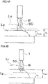
- For example, when laminating melt beads by arc welding using an automatic machine such as a robot, as illustrated in
Figs. 4A and 4B , there is a possibility that an actual height hnow of the melt bead may be different from a planned height hk of the melt bead. In this case, as illustrated inFig. 4A , when welding a bead Ln of the next layer to a bead Lp of a front layer, the shielding properties of shield gas SG may become unstable and this may affect the quality of the shaped object. As illustrated inFig. 4B , if the actual height hnow of the melt bead is higher than the planned height hk of the melt bead, when welding the bead Ln of the next layer, the bead Lp of the front layer interferes with an arc welding torch T or the filler material W and this adversely affects the quality of the shaped object and causes problems such as stopping the automatic machine and damage to the torch. - On the other hand, in a method of manufacturing a mold described in
Patent Document 1, there is room for improvement because error correction of the lamination height and height correction of a melt bead of each layer are not considered. - The invention is made in view of the problems described above and an object thereof is to provide a method, a system, and a program for manufacturing a laminate-molded object which can appropriately control the height of a melt bead of each layer to improve the quality of a shaped object and prevent interference between the melt bead and a laminating device.
- A method of, a system for and a program for manufacturing a laminate-molded object according to the present invention are defined in
claims - According to a method, a system, and a program for manufacturing a laminate-molded object of the invention, at the time of laminate molding, the height of a melt bead in each layer can be made as planned, and as a result, error with a previously planned molten metal lamination position can be suppressed to secure modeling accuracy. Further, since a distance between a welding torch and a laminated metal will be appropriate during molding, shielding properties by shield gas can be secured, which not only leads to quality assurance but also prevents damage due to collision with a laminating device such as a welding torch.
-
-
Fig. 1 is an external view of a system for manufacturing a laminate-molded object according to the invention. -
Fig. 2 is a flow chart of a program illustrating a procedure for forming the laminate-molded object. -
Fig. 3 is a view schematically illustrating a procedure for forming the laminate-molded object. -
Fig. 4A is a view schematically illustrating a case where a bead of a next layer is formed when an actual bead lamination position is lower than a planned bead lamination position. -
Fig. 4B is a view schematically illustrating a case where the bead of the next layer is formed when the actual bead lamination position is higher than the planned bead lamination position. - Hereinafter, an embodiment of a manufacturing method and a manufacturing system of a laminate-molded object according to the invention will be described in detail based on the drawings. The following embodiment is merely specific examples of the invention and do not limit the technical scope of the invention.
- As illustrated in
Fig. 1 , a laminate-moldedobject manufacturing system 10 according to the embodiment includes awelding robot 20, acutting robot 30, aheight measuring device 40, acontrol device 50, a CAD/CAM device 51, atrajectory planning unit 52, and amemory 53. That is, in the embodiment, the existingwelding robot 20 is used as the laminating device of the invention and the existingcutting robot 30 is used as the cutting device of the invention. - The laminate-molded
object manufacturing system 10 moves awelding torch 22 based on layer shape data representing the shapes of layers L1 to Lk of a laminate-moldedobject 11 andlaminates melt beads 61 over the plurality of layers L1 to Lk while melting a filler material (wire) W by thewelding robot 20, in such a manner that the laminate-moldedobject manufacturing system 10 forms the laminate-moldedobject 11. - In
Fig. 1 , a case where a substantially cylindrical shape is formed by continuously laminating themelt beads 61 helically (that is, an end portion of themelt bead 61 of a front layer and a start portion of themelt bead 61 of a next layer are continuous) is illustrated as an example of the laminate-moldedobject 11. However, the laminate-moldedobject 11 can be set to any shape. - The
welding robot 20 is an articulated robot and includes thewelding torch 22 at the tip portion of atip arm 21. Thetip arm 21 is movable in three dimensions, and by controlling the attitude and position of thetip arm 21 with thecontrol device 50, thewelding torch 22 can be moved to any position in any attitude. - The
welding torch 22 includes a substantially cylindrical shield nozzle to which shield gas SG (seeFig. 3 ) is supplied, a contact tip (not illustrated) disposed inside the shield nozzle, and a filler material W which is held by the contact tip and supplied with a melting current. While supplying the filler material W, thewelding torch 22 generates an arc while flowing the shield gas SG, in such a manner that thewelding torch 22 melts and solidifies the filler material W and laminates themelt beads 61 on abase 60 to form the laminate-moldedobject 11. Thewelding torch 22 may be a non-fusible electrode type that supplies a filler material from the outside. - The
cutting robot 30 is an articulated robot as similar to thewelding robot 20 and is provided with ametal processing tool 32 such as an end mill or a grinding wheel at the tip portion of thetip arm 31. Thus, thecutting robot 30 can be moved three-dimensionally by thecontrol device 50 so that the machining posture thereof can take any posture. - The
cutting robot 30 processes themelt bead 61 formed by thewelding robot 20 to the desired height withmetal processing tool 32, if necessary. - The
height measuring device 40 is a device for measuring a height hnow of themelt bead 61 and any height measuring device such as a contact type or a non-contact type can be used. However, themelt bead 61 immediately after formation is at a high temperature, it is preferable to use a non-contact-type measuring device such as a laser type or an imaging type. Theheight measuring device 40 measures the height hnow of themelt bead 61 every time one layer of themelt bead 61 is formed. - The CAD/
CAM device 51 creates shape data of the laminate-moldedobject 11 to be formed, and then divides it into a plurality of layers to generate layer shape data representing the shapes of the respective layers L1 to Lk. Thetrajectory planning unit 52 generates a moving trajectory of thewelding torch 22 based on the layer shape data. Thememory 53 stores the generated layer shape data, the movement trajectory of thewelding torch 22, and the like. - The
control device 50 controls thewelding robot 20 based on the layer shape data and the movement trajectory of thewelding torch 22, which are stored in thememory 53, by executing the manufacturing program stored inside and controls the movement of thewelding robot 20 and thecutting robot 30 according to the state of themelt bead 61 in each layer, as described below. - Next, with reference to
Figs. 2 and3 , a specific procedure of forming the laminate-moldedobject 11 using the laminate-moldedobject manufacturing system 10 of the embodiment will be described in detail. - As illustrated in the flow chart of
Fig. 2 , first, the shape data representing the shape of the laminate-moldedobject 11 is created by the CAD/CAM device 51 and the CAD/CAM device 51 divides the input shape data (CAD data) into a plurality of layers L1 to Lk and generates the layer shape data representing the shapes of the respective layers L1 to Lk (Step S1). The layer shape data representing the shapes of the respective layer L1 to Lk becomes the movement trajectory of thewelding torch 22, that is, the lamination trajectory of themelt bead 61. - It is preferable to divide the shape data of the laminate-molded
object 11 into the plurality of layers in a direction substantially perpendicular to a laminating direction of themelt beads 61. That is, when themelt beads 61 are vertically laminated to form the laminate-moldedobject 11, it is divided horizontally, and when themelt beads 61 are horizontally laminated to form the laminate-moldedobject 11, it is divided vertically. In the following description, a case where themelt beads 61 are vertically laminated to form the laminate-moldedobject 11 will be described. - Next, based on the layer shape data, the
trajectory planning unit 52 creates a specific melt-bead-61 laminating plan such as the movement trajectory of thewelding torch 22 in each of the layers L1 to Lk and a planned height hk of themelt bead 61 in which themelt beads 61 of the respective layers L1 to Lk are laminated (Step S2). - Then, the numerical value of the counter included in the
control device 50 is set to k=1 (Step S3) and the planned height hk of themelt bead 61 when themelt bead 61 of the first layer is laminated (formed) is set to hl (Step S4). In this case, the planned height hk is the total height of thelaminated melt beads 61. The planned height of themelt bead 61 for each of the layers L1 to Lk may be the same or the height may be different for each layer according to the layer shape data of each of the layers L1 to Lk. - Then, as illustrated in
Fig. 3 , thewelding torch 22 is moved along the planned movement trajectory and themelt bead 61 of the first layer is laminated on the base 60 (Step S5). Then, the height hnow of themelt bead 61 of the first layer is measured by theheight measuring device 40. In addition, the measurement of the height hnow of themelt bead 61 is performed every time themelt bead 61 of each of the layers L1 to Lk is formed. - Next, it is compared whether the height hnow of the
melt bead 61 measured is within the range of a tolerance ε with respect to the planned height hk. Specifically, it is determined whether the height hnow of themelt bead 61 measured is equal to or larger than a value obtained by subtracting the tolerance ε from the planned height hk (Step S6). - When, in Step S6, it is determined that the height hnow of the
melt bead 61 is smaller than the value obtained by subtracting the tolerance ε from the planned height hk, the process returns to Step S5 and anadditional melt bead 61a is further laminated on themelt bead 61 of the first layer, and further the height hnow of themelt bead 61 is measured again to compare with the planned height hk. - Thereby, the height hnow of the
melt bead 61 is brought close to the planned height hk. As a result, the adverse effect on the quality of the laminate-moldedobject 11 due to themelt bead 61 of the next layer being laminated while the height hnow of themelt bead 61 is smaller than the planned height hk can be suppressed. - Then, when it is determined that the height hnow of the
melt bead 61 is equal to or larger than a value obtained by subtracting the tolerance ε from the planned height hk, the process proceeds to the next step and it is determined whether the height hnow of themelt bead 61 is equal to or smaller than a value obtained by adding the tolerance ε to the planned height hk (Step S7). - When the height hnow of the
melt bead 61 is larger than the value obtained by adding the tolerance ε to the planned height hk, cutting is performed by themetal processing tool 32 of the cuttingrobot 30 so that the height hnow of themelt bead 61 becomes the planned height hk (Step S8). - After cutting the
melt bead 61 with the cuttingrobot 30, the process returns to Step S6 and the height hnow of themelt bead 61 after cutting is measured again by theheight measuring device 40 and compared with the planned height hk. Further, when cutting of themelt bead 61 ensures that the height hnow of themelt bead 61 is within the range of the tolerance ε with respect to the planned height hk, as indicated by the broken line inFig. 2 , the process may proceed to Step S9 of determining whether the planned number of layers ofmelt beads 61 is laminated. - In a case where, in Step S7, the height hnow of the
melt bead 61 is larger than the value obtained by adding the tolerance ε to the planned height hk, when themelt bead 61 of the next layer (the second layer) is laminated, thewelding torch 22 or the filler material W may come in contact with thelaminated melt bead 61 of the first layer, which may lead to stopping of thewelding robot 20 or damage to thewelding torch 22. However, this can be prevented by cutting the height hnow of themelt bead 61 to the planned height hk. - In a case where, in Step S7, the height hnow of the
melt bead 61 is equal to or smaller than the value obtained by adding the tolerance ε to the planned height hk, it is determined that the height hnow of themelt bead 61 is within the range of the tolerance ε, and then it is determined whether the planned number of layers of themelt beads 61 is laminated (Step S9). - When, in step S9, it is determined that the lamination of the planned number of layers of the
melt beads 61 is not completed, the value of the counter is incremented and set to k=2 (Step S10) and the process returns to Step S4. Then, the planned height hk is changed to a new planned height hk, which is the total height of themelt beads 61 of the first and second layers and themelt bead 61 of the next layer (second layer) is laminated on themelt bead 61 of the first layer. - Then, similarly, lamination of the
melt bead 61 is repeatedly performed until lamination of the planned number of layers of themelt beads 61 is completed, in such a manner that the laminate-moldedobject 11 is formed. - When it is determined in Step S9 that lamination of the planned number of layers of the
melt beads 61 is complete, the creation program for the laminate-moldedobject 11 is finished. - As described above, according to the method and system for manufacturing laminate-molded object of the embodiment, shape data representing the shape of laminate-molded
object 11 is acquired and the layer shape data representing the shape of each of the layers L1 to Lk is generated by dividing the laminate-moldedobject 11 into the plurality of layers L1 to Lk based on the shape data. Then, thewelding robot 20 forms the laminate-moldedobject 11 by laminating themelt beads 61 of respective layers L1 to Lk. The formation of themelt bead 61 of each of the layers L1 to Lk includes a step of forming themelt bead 61 by thewelding robot 20 based on the layer shape data of each of the layers L1 to Lk, a step of measuring the height hnow of the formedmelt bead 61 by theheight measuring device 40, a step of forming anothermelt bead 61a over themelt bead 61 with thewelding robot 20 when, comparing the height hnow of the measuredmelt bead 61 to the planned height hk within the range of the tolerances ε, the height hnow of themelt bead 61 is lower than the value obtained by subtracting the tolerance ε from the planned height hk, and a step of removing themelt bead 61 with the cuttingrobot 30 when the height hnow of themelt bead 61 is higher than the value obtained by adding the tolerance ε to the planned height hk. Therefore, it becomes possible to make the height hnow in each of the layers L1 to Lk within the range of the tolerance ε with respect to the planned height hk at the time of laminate molding, and as a result, it is possible to form the laminate-moldedobject 11 with high accuracy by suppressing an error with a previously planned molten metal lamination position. - Since the distance between the
welding torch 22 and themelt bead 61 is appropriate during molding, shielding properties by the shield gas can be secured. Therefore, not only does it lead to quality security, but it will also prevent stoppage and damage due to collisions of thewelding torch 22 or the filler material W with themelt bead 61. - Further, the comparison between the height hnow of the
melt bead 61 measured by theheight measuring device 40 and the planned height hk is performed again after laminating theadditional melt bead 61a or after cutting themelt bead 61 with the cuttingrobot 30, the laminate-moldedobject 11 can be formed with higher accuracy. - Further, according to the program for manufacturing the laminate-molded object of the embodiment, the
welding robot 20 performs the procedure of forming the laminate-moldedobject 11 by laminating and forming themelt bead 61 of each of the layers L1 to Lk. In addition, the formation of themelt bead 61 of each of the layers L1 to Lk executes a procedure of forming themelt bead 61 by thewelding robot 20 based on the layer shape data of each of the layers L1 to Lk, a procedure of measuring the height hnow of the formedmelt bead 61 by theheight measuring device 40, a procedure of forming anothermelt bead 61a over themelt bead 61 with thewelding robot 20 when, comparing the height hnow of the measuredmelt bead 61 to the planned height hk within the range of the tolerances ε, the height hnow of themelt bead 61 is lower than the value obtained by subtracting the tolerance ε from the planned height hk, and a procedure of removing themelt bead 61 with the cuttingrobot 30 when the height hnow of themelt bead 61 is higher than the value obtained by adding the tolerance ε to the planned height hk. Therefore, it becomes possible to make the height hnow in each of the layers L1 to Lk within the range of the tolerance ε with respect to the planned height hk at the time of laminate molding, and as a result, it is possible to form the laminate-moldedobject 11 with high accuracy by suppressing an error with a previously planned molten metal lamination position. - In Step S6, when laminating another
melt bead 61a, a different filler material W and a different welding torch may also be used to laminate anothermelt bead 61a of appropriate height according to the lamination error, with different welding conditions. Alternatively, anothermelt bead 61a may be laminated under the same conditions as those of themelt bead 61 in anticipation of the cutting process in Step S8 in advance. - The invention is not limited to the embodiment described above and appropriate modifications, improvements, and the like can be made.
- For example, in the embodiment described above, an example in which arc welding is applied as the melt lamination method is described. However, a laminating device by other metal molding lamination method, for example, a molding lamination method by laser such as Selective Laser Melting (SLM) or Laser Metal Deposition (LMD), electron beam welding, or the like are also applicable.
-
- 10
- laminate-molded object manufacturing system
- 11
- laminate-molded object
- 20
- welding robot (laminating device)
- 30
- cutting robot (cutting device)
- 40
- height measuring device
- 50
- control device
- 61
- melt bead
- 61a
- another melt bead
- L1 to Lk
- layers
- ε
- tolerance
- hnow
- height of a melt bead
- hk
- planned height of a melt bead (planned height)
Claims (4)
- A method of manufacturing a laminate-molded object, comprising:acquiring shape data representing the shape of a shaped object;dividing the shaped object into a plurality of parallel layers based on the shape data and generating layer shape data representing the shape of each layer; andproviding a control device;the method being characterized by achieving the following steps under the control of the control device:forming a melt bead of each layer and laminating the melt bead until the shape of the shaped object is formed, whereinthe formation of the melt bead of each layer includes:forming the melt bead by a laminating device based on the layer shape data of each layer;measuring the height of the formed melt bead;comparing whether the measured height of the melt bead is within a range of a tolerance with respect to a planned height;forming another melt bead over the melt bead when the height of the melt bead is lower than a value obtained by subtracting the tolerance with respect to the planned height; andremoving the melt bead when the height of the melt bead is higher than a value obtained by adding the tolerance to the planned height, whereinthe forming of the melt bead and the removing of the melt bead are performed by an articulated welding robot and an articulated cutting robot, respectively.
- The method according to claim 1, wherein
the measuring and the comparing are performed again after the another melt bead forming or the melt bead removing is performed. - A system for manufacturing a laminate-molded object, comprising:a laminating device comprising an articulated robot for forming melt beads of a plurality of layers based on layer shape data representing the shape of the layers, in which a shaped object is divided into the plurality of layers parallel to each other;and being characterized by:a cutting device comprising an articulated robot for cutting the melt bead formed by the laminating device;a height measuring device for measuring the height of the formed melt bead; anda control device which controls the laminating device to form the melt bead of the plurality of layers based on the layer shape data of each layer, controls the laminating device to form another melt bead over the melt bead when the height of the melt bead measured by the height measuring device for each formation of the melt bead of each layer is lower than a value obtained by subtracting a tolerance from a planned height, and controls the cutting device to remove the melt bead when the height of the melt bead is higher than a value obtained by adding the tolerance to the planned height.
- A program for manufacturing a laminate-molded object, causing a computer to execute a process when installed in the device of claim 3, the process being characterized by comprising:forming a melt bead of each layer by controlling an articulated welding robot and using layer shape data representing the shape of each layer, in which the shape object is divided into a plurality of layers based on shape data representing the shape of the shape object, and performing a procedure of laminating the melt bead until the shape of the shaped object is formed, whereinthe formation of the melt bead of each layer includes:forming the melt bead by a laminating device based on the layer shape data of each layer;measuring the height of the formed melt bead;comparing whether the measured height of the melt bead is within a range of a tolerance with respect to a planned height;forming another melt bead over the melt bead when the height of the melt bead is lower than a value obtained by subtracting the tolerance from the planned height; andremoving the melt bead by controlling an articulated cutting robot, when the height of the melt bead is higher than a value obtained by adding the tolerance to the planned height.
Applications Claiming Priority (2)
| Application Number | Priority Date | Filing Date | Title |
|---|---|---|---|
| JP2017047553A JP6751040B2 (en) | 2017-03-13 | 2017-03-13 | Manufacturing method, manufacturing system, and manufacturing program for layered product |
| PCT/JP2018/009819 WO2018168881A1 (en) | 2017-03-13 | 2018-03-13 | Manufacturing method, manufacturing system, and manufacturing program for additive manufactured object |
Publications (3)
| Publication Number | Publication Date |
|---|---|
| EP3597342A1 EP3597342A1 (en) | 2020-01-22 |
| EP3597342A4 EP3597342A4 (en) | 2021-01-20 |
| EP3597342B1 true EP3597342B1 (en) | 2022-08-17 |
Family
ID=63523902
Family Applications (1)
| Application Number | Title | Priority Date | Filing Date |
|---|---|---|---|
| EP18768083.0A Active EP3597342B1 (en) | 2017-03-13 | 2018-03-13 | Manufacturing method, manufacturing system, and manufacturing program for additive manufactured object |
Country Status (5)
| Country | Link |
|---|---|
| US (1) | US20190381595A1 (en) |
| EP (1) | EP3597342B1 (en) |
| JP (1) | JP6751040B2 (en) |
| CN (1) | CN110430959B (en) |
| WO (1) | WO2018168881A1 (en) |
Families Citing this family (20)
| Publication number | Priority date | Publication date | Assignee | Title |
|---|---|---|---|---|
| JP7010799B2 (en) * | 2018-10-16 | 2022-01-26 | 株式会社神戸製鋼所 | Structure manufacturing method and structure |
| JP7310829B2 (en) * | 2018-10-31 | 2023-07-19 | 株式会社ニコン | Machining system and machining method |
| JP7223644B2 (en) * | 2019-06-20 | 2023-02-16 | 株式会社神戸製鋼所 | Modeled article manufacturing method and modeled article manufacturing control method |
| US20220324057A1 (en) * | 2019-08-07 | 2022-10-13 | Mitsubishi Electric Corporation | Additive manufacturing apparatus, additive manufacturing method, and storage medium |
| WO2021064952A1 (en) * | 2019-10-03 | 2021-04-08 | 三菱電機株式会社 | Processing program generating device, laminate molding device, processing program generating method, laminate molding method, and machine learning device |
| JP7388212B2 (en) * | 2020-01-31 | 2023-11-29 | セイコーエプソン株式会社 | Three-dimensional object manufacturing method and three-dimensional printing device |
| JP7391709B2 (en) * | 2020-02-17 | 2023-12-05 | 株式会社神戸製鋼所 | Modeled object manufacturing method, modeled object manufacturing device, and program |
| US20230101500A1 (en) * | 2020-03-19 | 2023-03-30 | Mitsubishi Electric Corporation | Additive manufacturing path generation apparatus, additive manufacturing path generation method, and machine learning apparatus |
| JP7384760B2 (en) * | 2020-07-15 | 2023-11-21 | 株式会社神戸製鋼所 | Machine learning device, additive manufacturing system, machine learning method for welding conditions, method for adjusting welding conditions, and program |
| JP7303162B2 (en) * | 2020-07-15 | 2023-07-04 | 株式会社神戸製鋼所 | Laminate-molded article manufacturing method |
| JP7339215B2 (en) * | 2020-07-20 | 2023-09-05 | 株式会社神戸製鋼所 | Laminate-molded article manufacturing system, laminate-molded article manufacturing method, and laminate-molded article manufacturing program |
| JP6912636B1 (en) | 2020-08-19 | 2021-08-04 | 株式会社神戸製鋼所 | Laminated model manufacturing system, laminated model manufacturing method, and laminated model manufacturing program |
| JP7376455B2 (en) * | 2020-10-28 | 2023-11-08 | 株式会社神戸製鋼所 | How to create a layered plan |
| JP7553400B2 (en) * | 2021-04-16 | 2024-09-18 | 株式会社神戸製鋼所 | Layered manufacturing method, layered manufacturing device, and program for manufacturing layered object |
| JP7469264B2 (en) | 2021-07-28 | 2024-04-16 | 株式会社神戸製鋼所 | Method for controlling molding apparatus, molding apparatus, and program |
| KR102513393B1 (en) * | 2021-08-31 | 2023-03-23 | 한국생산기술연구원 | Method for manufacturing Ni-Al-Bronze propeller using wire-arc additive manufacturing process |
| KR102591784B1 (en) * | 2021-10-29 | 2023-10-23 | 한국생산기술연구원 | Pre-Simulated Laminating Material Properties Diagnosing Method Using 3D Printing Type Building Materials Feeding Apparatus |
| JP2023169061A (en) * | 2022-05-16 | 2023-11-29 | 株式会社神戸製鋼所 | Control method for weld bead shape, power supply control method, lamination molding method, control device, power supply device, welding system, lamination molding system, and program |
| EP4400243A1 (en) * | 2023-01-11 | 2024-07-17 | Fundación AITIIP | Method of additive manufacturing for manufacturing molds an additive manufacturing system for manufacturing molds |
| WO2024166230A1 (en) * | 2023-02-08 | 2024-08-15 | 三菱電機株式会社 | Defect estimation device, numerical control device, additive manufacturing device, and defect estimation method |
Citations (1)
| Publication number | Priority date | Publication date | Assignee | Title |
|---|---|---|---|---|
| US20150108096A1 (en) * | 2013-10-22 | 2015-04-23 | Lincoln Global, Inc. | Systems and methods providing location feedback for additive manufacturing |
Family Cites Families (19)
| Publication number | Priority date | Publication date | Assignee | Title |
|---|---|---|---|---|
| US5207371A (en) * | 1991-07-29 | 1993-05-04 | Prinz Fritz B | Method and apparatus for fabrication of three-dimensional metal articles by weld deposition |
| JP3784539B2 (en) | 1998-07-01 | 2006-06-14 | 本田技研工業株式会社 | Mold manufacturing method |
| DE10344901B4 (en) * | 2002-09-30 | 2006-09-07 | Matsushita Electric Works, Ltd., Kadoma | Method for producing a three-dimensional sintered product |
| JP2004230431A (en) * | 2003-01-31 | 2004-08-19 | Fujitsu Ltd | Information processing method for working object and program |
| US7358457B2 (en) * | 2006-02-22 | 2008-04-15 | General Electric Company | Nozzle for laser net shape manufacturing |
| JP5190023B2 (en) * | 2009-05-20 | 2013-04-24 | 株式会社神戸製鋼所 | Welding setting device, welding robot system, and welding setting program |
| FR2983424B1 (en) * | 2011-12-02 | 2014-09-19 | Nantes Ecole Centrale | METHOD AND APPARATUS FOR COMBINED MATERIAL ADDITION MACHINING AND SHAPING |
| CN103374721B (en) * | 2012-04-27 | 2015-06-03 | 沈阳新松机器人自动化股份有限公司 | Real-time online data acquisition and remote monitoring system used for roller laser cladding |
| US11235409B2 (en) * | 2013-10-18 | 2022-02-01 | +Mfg, LLC | Method and apparatus for fabrication of articles by molten and semi-molten deposition |
| JP5878604B1 (en) * | 2014-10-21 | 2016-03-08 | アドバンスト・リサーチ・フォー・マニュファクチャリング・システムズ・リミテッド・ライアビリティ・カンパニーAdvanced Research For Manufacturing Systems, Llc | Manufacturing method of composite material |
| US10766802B2 (en) * | 2014-11-29 | 2020-09-08 | National Tsing Hua University | Flexible 3D freeform techniques |
| CN204524771U (en) * | 2014-12-30 | 2015-08-05 | 深圳市圆梦精密技术研究院 | Lf and laser milling compound 3D printing device |
| US10421267B2 (en) * | 2015-02-12 | 2019-09-24 | Arevo, Inc. | Method to monitor additive manufacturing process for detection and in-situ correction of defects |
| US20180071987A1 (en) * | 2015-03-12 | 2018-03-15 | Nikon Corporation | Apparatus for manufacturing three dimensional shaped object, and method for manufacturing structure |
| US20170008114A1 (en) * | 2015-07-09 | 2017-01-12 | Lincoln Global, Inc. | System and method of controlling attachment and release of additive manufacturing builds using a welding process |
| JP6447422B2 (en) | 2015-08-31 | 2019-01-09 | 住友金属鉱山株式会社 | Cylindrical forming mold, cylindrical ceramic molded body and manufacturing method thereof |
| CN105499904B (en) * | 2016-01-04 | 2017-12-08 | 湘潭大学 | A kind of part prosthetic device and its application method based on increase and decrease material manufacture |
| CN106425490B (en) * | 2016-09-05 | 2018-06-29 | 华中科技大学 | A kind of increase and decrease material combined-machining equipment and its application |
| EP3338935A1 (en) * | 2016-12-22 | 2018-06-27 | MAN Truck & Bus AG | 3d printing apparatus |
-
2017
- 2017-03-13 JP JP2017047553A patent/JP6751040B2/en active Active
-
2018
- 2018-03-13 WO PCT/JP2018/009819 patent/WO2018168881A1/en unknown
- 2018-03-13 EP EP18768083.0A patent/EP3597342B1/en active Active
- 2018-03-13 US US16/489,633 patent/US20190381595A1/en not_active Abandoned
- 2018-03-13 CN CN201880018298.5A patent/CN110430959B/en active Active
Patent Citations (1)
| Publication number | Priority date | Publication date | Assignee | Title |
|---|---|---|---|---|
| US20150108096A1 (en) * | 2013-10-22 | 2015-04-23 | Lincoln Global, Inc. | Systems and methods providing location feedback for additive manufacturing |
Also Published As
| Publication number | Publication date |
|---|---|
| CN110430959B (en) | 2021-06-04 |
| JP2018149570A (en) | 2018-09-27 |
| EP3597342A4 (en) | 2021-01-20 |
| CN110430959A (en) | 2019-11-08 |
| WO2018168881A1 (en) | 2018-09-20 |
| EP3597342A1 (en) | 2020-01-22 |
| US20190381595A1 (en) | 2019-12-19 |
| JP6751040B2 (en) | 2020-09-02 |
Similar Documents
| Publication | Publication Date | Title |
|---|---|---|
| EP3597342B1 (en) | Manufacturing method, manufacturing system, and manufacturing program for additive manufactured object | |
| EP3815826A1 (en) | Laminated molded object production method and production device | |
| EP3711887B1 (en) | Method and apparatus for manufacturing layered model | |
| EP3711888B1 (en) | Method and device for manufacturing shaped objects | |
| WO2018180135A1 (en) | Method and system for manufacturing laminated shaped product | |
| KR20160088936A (en) | Machine tool, measurement apparatus, method for generating work data, cladding method, method for setting temperature of a workpiece | |
| US12017309B2 (en) | Method for setting excess thickness, device for setting excess thickness, method for producing shaped object, and program | |
| US11666985B2 (en) | Gradient material control and programming of additive manufacturing processes | |
| US20170297323A1 (en) | Method for generating control data, data processing device, machine tool, and program | |
| EP3196004B1 (en) | Three-dimensional shaping method | |
| CN111770806B (en) | Method for forming layered formed article, apparatus for producing layered formed article, and recording medium | |
| US12005529B2 (en) | Method for manufacturing laminated molding, and laminated molding | |
| Campocasso et al. | A framework for future CAM software dedicated to additive manufacturing by multi-axis deposition | |
| Bernauer et al. | Segmentation-based closed-loop layer height control for enhancing stability and dimensional accuracy in wire-based laser metal deposition | |
| EP3711889A1 (en) | Method for producing molded article, production device, and molded article | |
| US20210299753A1 (en) | Method for the Additive Manufacture of a Plurality of Motor Vehicle Components | |
| JP7160768B2 (en) | Laminate-molded article setting method, laminate-molded article manufacturing method, and manufacturing apparatus | |
| JP2024089144A (en) | Manufacturing method and manufacturing device for molded object | |
| Naseri et al. | Deposition path planning strategy for geometries with varying cross-sections in wire arc additive manufacturing | |
| JP2024072589A (en) | Control device, control method and program of robot | |
| Christiansson et al. | Automation of a robotised metal deposition system using laser melting of wire |
Legal Events
| Date | Code | Title | Description |
|---|---|---|---|
| STAA | Information on the status of an ep patent application or granted ep patent |
Free format text: STATUS: THE INTERNATIONAL PUBLICATION HAS BEEN MADE |
|
| PUAI | Public reference made under article 153(3) epc to a published international application that has entered the european phase |
Free format text: ORIGINAL CODE: 0009012 |
|
| STAA | Information on the status of an ep patent application or granted ep patent |
Free format text: STATUS: REQUEST FOR EXAMINATION WAS MADE |
|
| 17P | Request for examination filed |
Effective date: 20190822 |
|
| AK | Designated contracting states |
Kind code of ref document: A1 Designated state(s): AL AT BE BG CH CY CZ DE DK EE ES FI FR GB GR HR HU IE IS IT LI LT LU LV MC MK MT NL NO PL PT RO RS SE SI SK SM TR |
|
| AX | Request for extension of the european patent |
Extension state: BA ME |
|
| DAV | Request for validation of the european patent (deleted) | ||
| DAX | Request for extension of the european patent (deleted) | ||
| A4 | Supplementary search report drawn up and despatched |
Effective date: 20201223 |
|
| RIC1 | Information provided on ipc code assigned before grant |
Ipc: B33Y 50/02 20150101ALI20201217BHEP Ipc: B23K 26/342 20140101ALI20201217BHEP Ipc: B22F 3/105 20060101ALI20201217BHEP Ipc: B23K 9/04 20060101AFI20201217BHEP Ipc: B33Y 10/00 20150101ALI20201217BHEP Ipc: B33Y 30/00 20150101ALI20201217BHEP Ipc: B23K 15/00 20060101ALI20201217BHEP |
|
| RIC1 | Information provided on ipc code assigned before grant |
Ipc: B23K 15/00 20060101ALI20210928BHEP Ipc: B23K 26/342 20140101ALI20210928BHEP Ipc: B22F 3/105 20060101ALI20210928BHEP Ipc: B33Y 50/02 20150101ALI20210928BHEP Ipc: B33Y 30/00 20150101ALI20210928BHEP Ipc: B33Y 10/00 20150101ALI20210928BHEP Ipc: B23K 9/04 20060101AFI20210928BHEP |
|
| GRAP | Despatch of communication of intention to grant a patent |
Free format text: ORIGINAL CODE: EPIDOSNIGR1 |
|
| STAA | Information on the status of an ep patent application or granted ep patent |
Free format text: STATUS: GRANT OF PATENT IS INTENDED |
|
| INTG | Intention to grant announced |
Effective date: 20211110 |
|
| GRAJ | Information related to disapproval of communication of intention to grant by the applicant or resumption of examination proceedings by the epo deleted |
Free format text: ORIGINAL CODE: EPIDOSDIGR1 |
|
| STAA | Information on the status of an ep patent application or granted ep patent |
Free format text: STATUS: REQUEST FOR EXAMINATION WAS MADE |
|
| GRAP | Despatch of communication of intention to grant a patent |
Free format text: ORIGINAL CODE: EPIDOSNIGR1 |
|
| STAA | Information on the status of an ep patent application or granted ep patent |
Free format text: STATUS: GRANT OF PATENT IS INTENDED |
|
| INTC | Intention to grant announced (deleted) | ||
| INTG | Intention to grant announced |
Effective date: 20220309 |
|
| GRAS | Grant fee paid |
Free format text: ORIGINAL CODE: EPIDOSNIGR3 |
|
| GRAA | (expected) grant |
Free format text: ORIGINAL CODE: 0009210 |
|
| STAA | Information on the status of an ep patent application or granted ep patent |
Free format text: STATUS: THE PATENT HAS BEEN GRANTED |
|
| AK | Designated contracting states |
Kind code of ref document: B1 Designated state(s): AL AT BE BG CH CY CZ DE DK EE ES FI FR GB GR HR HU IE IS IT LI LT LU LV MC MK MT NL NO PL PT RO RS SE SI SK SM TR |
|
| REG | Reference to a national code |
Ref country code: CH Ref legal event code: EP |
|
| REG | Reference to a national code |
Ref country code: DE Ref legal event code: R096 Ref document number: 602018039449 Country of ref document: DE |
|
| REG | Reference to a national code |
Ref country code: IE Ref legal event code: FG4D |
|
| REG | Reference to a national code |
Ref country code: AT Ref legal event code: REF Ref document number: 1511849 Country of ref document: AT Kind code of ref document: T Effective date: 20220915 |
|
| REG | Reference to a national code |
Ref country code: NL Ref legal event code: MP Effective date: 20220817 |
|
| REG | Reference to a national code |
Ref country code: LT Ref legal event code: MG9D |
|
| PG25 | Lapsed in a contracting state [announced via postgrant information from national office to epo] |
Ref country code: SE Free format text: LAPSE BECAUSE OF FAILURE TO SUBMIT A TRANSLATION OF THE DESCRIPTION OR TO PAY THE FEE WITHIN THE PRESCRIBED TIME-LIMIT Effective date: 20220817 Ref country code: RS Free format text: LAPSE BECAUSE OF FAILURE TO SUBMIT A TRANSLATION OF THE DESCRIPTION OR TO PAY THE FEE WITHIN THE PRESCRIBED TIME-LIMIT Effective date: 20220817 Ref country code: PT Free format text: LAPSE BECAUSE OF FAILURE TO SUBMIT A TRANSLATION OF THE DESCRIPTION OR TO PAY THE FEE WITHIN THE PRESCRIBED TIME-LIMIT Effective date: 20221219 Ref country code: NO Free format text: LAPSE BECAUSE OF FAILURE TO SUBMIT A TRANSLATION OF THE DESCRIPTION OR TO PAY THE FEE WITHIN THE PRESCRIBED TIME-LIMIT Effective date: 20221117 Ref country code: NL Free format text: LAPSE BECAUSE OF FAILURE TO SUBMIT A TRANSLATION OF THE DESCRIPTION OR TO PAY THE FEE WITHIN THE PRESCRIBED TIME-LIMIT Effective date: 20220817 Ref country code: LV Free format text: LAPSE BECAUSE OF FAILURE TO SUBMIT A TRANSLATION OF THE DESCRIPTION OR TO PAY THE FEE WITHIN THE PRESCRIBED TIME-LIMIT Effective date: 20220817 Ref country code: LT Free format text: LAPSE BECAUSE OF FAILURE TO SUBMIT A TRANSLATION OF THE DESCRIPTION OR TO PAY THE FEE WITHIN THE PRESCRIBED TIME-LIMIT Effective date: 20220817 Ref country code: FI Free format text: LAPSE BECAUSE OF FAILURE TO SUBMIT A TRANSLATION OF THE DESCRIPTION OR TO PAY THE FEE WITHIN THE PRESCRIBED TIME-LIMIT Effective date: 20220817 |
|
| REG | Reference to a national code |
Ref country code: AT Ref legal event code: MK05 Ref document number: 1511849 Country of ref document: AT Kind code of ref document: T Effective date: 20220817 |
|
| PG25 | Lapsed in a contracting state [announced via postgrant information from national office to epo] |
Ref country code: PL Free format text: LAPSE BECAUSE OF FAILURE TO SUBMIT A TRANSLATION OF THE DESCRIPTION OR TO PAY THE FEE WITHIN THE PRESCRIBED TIME-LIMIT Effective date: 20220817 Ref country code: IS Free format text: LAPSE BECAUSE OF FAILURE TO SUBMIT A TRANSLATION OF THE DESCRIPTION OR TO PAY THE FEE WITHIN THE PRESCRIBED TIME-LIMIT Effective date: 20221217 Ref country code: HR Free format text: LAPSE BECAUSE OF FAILURE TO SUBMIT A TRANSLATION OF THE DESCRIPTION OR TO PAY THE FEE WITHIN THE PRESCRIBED TIME-LIMIT Effective date: 20220817 Ref country code: GR Free format text: LAPSE BECAUSE OF FAILURE TO SUBMIT A TRANSLATION OF THE DESCRIPTION OR TO PAY THE FEE WITHIN THE PRESCRIBED TIME-LIMIT Effective date: 20221118 |
|
| PG25 | Lapsed in a contracting state [announced via postgrant information from national office to epo] |
Ref country code: SM Free format text: LAPSE BECAUSE OF FAILURE TO SUBMIT A TRANSLATION OF THE DESCRIPTION OR TO PAY THE FEE WITHIN THE PRESCRIBED TIME-LIMIT Effective date: 20220817 Ref country code: RO Free format text: LAPSE BECAUSE OF FAILURE TO SUBMIT A TRANSLATION OF THE DESCRIPTION OR TO PAY THE FEE WITHIN THE PRESCRIBED TIME-LIMIT Effective date: 20220817 Ref country code: ES Free format text: LAPSE BECAUSE OF FAILURE TO SUBMIT A TRANSLATION OF THE DESCRIPTION OR TO PAY THE FEE WITHIN THE PRESCRIBED TIME-LIMIT Effective date: 20220817 Ref country code: DK Free format text: LAPSE BECAUSE OF FAILURE TO SUBMIT A TRANSLATION OF THE DESCRIPTION OR TO PAY THE FEE WITHIN THE PRESCRIBED TIME-LIMIT Effective date: 20220817 Ref country code: CZ Free format text: LAPSE BECAUSE OF FAILURE TO SUBMIT A TRANSLATION OF THE DESCRIPTION OR TO PAY THE FEE WITHIN THE PRESCRIBED TIME-LIMIT Effective date: 20220817 Ref country code: AT Free format text: LAPSE BECAUSE OF FAILURE TO SUBMIT A TRANSLATION OF THE DESCRIPTION OR TO PAY THE FEE WITHIN THE PRESCRIBED TIME-LIMIT Effective date: 20220817 |
|
| REG | Reference to a national code |
Ref country code: DE Ref legal event code: R097 Ref document number: 602018039449 Country of ref document: DE |
|
| PG25 | Lapsed in a contracting state [announced via postgrant information from national office to epo] |
Ref country code: SK Free format text: LAPSE BECAUSE OF FAILURE TO SUBMIT A TRANSLATION OF THE DESCRIPTION OR TO PAY THE FEE WITHIN THE PRESCRIBED TIME-LIMIT Effective date: 20220817 Ref country code: EE Free format text: LAPSE BECAUSE OF FAILURE TO SUBMIT A TRANSLATION OF THE DESCRIPTION OR TO PAY THE FEE WITHIN THE PRESCRIBED TIME-LIMIT Effective date: 20220817 |
|
| PLBE | No opposition filed within time limit |
Free format text: ORIGINAL CODE: 0009261 |
|
| STAA | Information on the status of an ep patent application or granted ep patent |
Free format text: STATUS: NO OPPOSITION FILED WITHIN TIME LIMIT |
|
| P01 | Opt-out of the competence of the unified patent court (upc) registered |
Effective date: 20230523 |
|
| PG25 | Lapsed in a contracting state [announced via postgrant information from national office to epo] |
Ref country code: AL Free format text: LAPSE BECAUSE OF FAILURE TO SUBMIT A TRANSLATION OF THE DESCRIPTION OR TO PAY THE FEE WITHIN THE PRESCRIBED TIME-LIMIT Effective date: 20220817 |
|
| 26N | No opposition filed |
Effective date: 20230519 |
|
| PG25 | Lapsed in a contracting state [announced via postgrant information from national office to epo] |
Ref country code: SI Free format text: LAPSE BECAUSE OF FAILURE TO SUBMIT A TRANSLATION OF THE DESCRIPTION OR TO PAY THE FEE WITHIN THE PRESCRIBED TIME-LIMIT Effective date: 20220817 |
|
| PG25 | Lapsed in a contracting state [announced via postgrant information from national office to epo] |
Ref country code: MC Free format text: LAPSE BECAUSE OF FAILURE TO SUBMIT A TRANSLATION OF THE DESCRIPTION OR TO PAY THE FEE WITHIN THE PRESCRIBED TIME-LIMIT Effective date: 20220817 |
|
| REG | Reference to a national code |
Ref country code: CH Ref legal event code: PL |
|
| REG | Reference to a national code |
Ref country code: BE Ref legal event code: MM Effective date: 20230331 |
|
| PG25 | Lapsed in a contracting state [announced via postgrant information from national office to epo] |
Ref country code: LU Free format text: LAPSE BECAUSE OF NON-PAYMENT OF DUE FEES Effective date: 20230313 |
|
| REG | Reference to a national code |
Ref country code: IE Ref legal event code: MM4A |
|
| PG25 | Lapsed in a contracting state [announced via postgrant information from national office to epo] |
Ref country code: LI Free format text: LAPSE BECAUSE OF NON-PAYMENT OF DUE FEES Effective date: 20230331 Ref country code: IE Free format text: LAPSE BECAUSE OF NON-PAYMENT OF DUE FEES Effective date: 20230313 Ref country code: CH Free format text: LAPSE BECAUSE OF NON-PAYMENT OF DUE FEES Effective date: 20230331 |
|
| PG25 | Lapsed in a contracting state [announced via postgrant information from national office to epo] |
Ref country code: BE Free format text: LAPSE BECAUSE OF NON-PAYMENT OF DUE FEES Effective date: 20230331 |
|
| PGFP | Annual fee paid to national office [announced via postgrant information from national office to epo] |
Ref country code: DE Payment date: 20240130 Year of fee payment: 7 Ref country code: GB Payment date: 20240201 Year of fee payment: 7 |
|
| PGFP | Annual fee paid to national office [announced via postgrant information from national office to epo] |
Ref country code: IT Payment date: 20240212 Year of fee payment: 7 Ref country code: FR Payment date: 20240213 Year of fee payment: 7 |