EP3597090A1 - Saugroboter, ladestation für einen saugroboter und verfahren zum betreiben eines saugroboters - Google Patents
Saugroboter, ladestation für einen saugroboter und verfahren zum betreiben eines saugroboters Download PDFInfo
- Publication number
- EP3597090A1 EP3597090A1 EP19180530.8A EP19180530A EP3597090A1 EP 3597090 A1 EP3597090 A1 EP 3597090A1 EP 19180530 A EP19180530 A EP 19180530A EP 3597090 A1 EP3597090 A1 EP 3597090A1
- Authority
- EP
- European Patent Office
- Prior art keywords
- sensor housing
- robot
- housing
- sensor
- vacuum
- Prior art date
- Legal status (The legal status is an assumption and is not a legal conclusion. Google has not performed a legal analysis and makes no representation as to the accuracy of the status listed.)
- Granted
Links
Images




Classifications
-
- A—HUMAN NECESSITIES
- A47—FURNITURE; DOMESTIC ARTICLES OR APPLIANCES; COFFEE MILLS; SPICE MILLS; SUCTION CLEANERS IN GENERAL
- A47L—DOMESTIC WASHING OR CLEANING; SUCTION CLEANERS IN GENERAL
- A47L9/00—Details or accessories of suction cleaners, e.g. mechanical means for controlling the suction or for effecting pulsating action; Storing devices specially adapted to suction cleaners or parts thereof; Carrying-vehicles specially adapted for suction cleaners
-
- A—HUMAN NECESSITIES
- A47—FURNITURE; DOMESTIC ARTICLES OR APPLIANCES; COFFEE MILLS; SPICE MILLS; SUCTION CLEANERS IN GENERAL
- A47L—DOMESTIC WASHING OR CLEANING; SUCTION CLEANERS IN GENERAL
- A47L2201/00—Robotic cleaning machines, i.e. with automatic control of the travelling movement or the cleaning operation
- A47L2201/02—Docking stations; Docking operations
-
- A—HUMAN NECESSITIES
- A47—FURNITURE; DOMESTIC ARTICLES OR APPLIANCES; COFFEE MILLS; SPICE MILLS; SUCTION CLEANERS IN GENERAL
- A47L—DOMESTIC WASHING OR CLEANING; SUCTION CLEANERS IN GENERAL
- A47L2201/00—Robotic cleaning machines, i.e. with automatic control of the travelling movement or the cleaning operation
- A47L2201/04—Automatic control of the travelling movement; Automatic obstacle detection
Definitions
- the invention relates to a vacuum robot, a charging station for a vacuum robot and a method for operating a vacuum robot
- a vacuum robot can have a sensor device which is designed to be both vertically movable and rotatable in rotation.
- the movement of the sensor housing is usually generated via a motor drive device.
- the US 9 283 670 B2 describes such a vacuum robot with a sensor housing which can be moved by means of a drive device and which can be moved in order to set a detection range of the sensor.
- the object of the invention is to provide an improved vacuum robot, an improved charging station for a vacuum robot and an improved method for operating a vacuum robot.
- this object is achieved by a vacuum robot, a charging station for a vacuum robot and a method for operating a vacuum robot with the features or steps of the main claims.
- a sensor housing of the vacuum robot can protrude beyond a device surface of the vacuum robot to enable an all-round view of an environment sensor.
- the sensor housing can be pulled into the vacuum robot.
- This advantageously enables efficient navigation and efficient reaching and cleaning despite obstacles and a compact construction of the robot vacuum.
- the retraction of the sensor housing can take place without a motorized drive device, and is therefore advantageously energy-saving.
- a vacuum robot has a robot housing, a sensor housing and an elastic element.
- the sensor housing for receiving an environment sensor for the vacuum robot is at least partially arranged in the robot housing.
- the elastic element is designed to pretension the sensor housing from a retracted position in the direction of an extended position. In the extended position, a section of the sensor housing protrudes from the robot housing. In the retracted position, the partial section of the sensor housing is at least partially arranged in the robot housing.
- the elastic element can be deformed by a retracting force in order to enable the sensor housing to move from the extended position in the direction of the retracted position.
- a height-variable sensor can thus be implemented.
- the elastic element can be, for example, a spring such as a compression spring or a helical tension spring, or an elastomer element.
- the extended position can be used, for example, when navigating the vacuum robot in an unknown environment if an environment sensor, for example a lidar sensor, is accommodated in the sensor housing.
- the retract position can be used, for example, to reach an area below a low obstacle, such as low furniture.
- the sensor housing In the extended position, for example, the sensor housing can protrude from the robot housing by ten to forty percent of a device height of the robot vacuum cleaner over a surface.
- an upper end of the sensor housing can, for example, be at the same height as the robot housing, or can protrude less than ten percent of the device height above the robot housing.
- the retraction force can be, for example, a mechanical pressure effect or another force effect, for example a magnetic force.
- the sensor housing can have a run-up slope in the section for introducing the entry force onto the sensor housing and the elastic element.
- the run-up slope can be, for example, a circumferential slope of the section.
- the sensor housing can be pressed into the robot housing when driving under a low object, and after passing the obstacle, the sensor housing can be automatically moved back into the extended position by means of the elastic element, which is advantageously energy-saving.
- the sensor housing in the subsection can have at least one impeller for introducing the entry force onto the sensor housing and the elastic element.
- the impeller can, for example, be arranged fixed on the section.
- the section can also have a plurality of impellers which are arranged, for example, all around the section. If the section has the run-up slope, the run-up wheel can be arranged on the run-up slope.
- the impeller can advantageously prevent damage, for example scratching, of the sensor housing when the obstacle or the structure for introducing the retracting force is approached in the form of a mechanical pressure.
- jamming of the sensor housing in the obstacle or in the structure can advantageously be prevented by means of the impeller.
- the vacuum robot can also have a locking unit.
- the locking unit can be designed to lock the sensor housing in the retracted position. This is advantageous, for example, if the sensor housing is to remain in the retracted position under an obstacle, such as a low cabinet, during a cleaning process of the robot vacuum cleaner, in order to enable the area under the obstacle to be reached and to prevent the sensor housing from being damaged by the obstacle.
- the robot housing of the vacuum robot can have a groove adjacent to the sensor housing for introducing the retracting force in order to sink the sensor housing into the robot housing.
- the groove can, for example, be formed all around the sensor housing.
- the groove can be designed to enable movement of the sensor housing into a locking position in response to the retracting force, the sensor housing being arranged in the locking position within the robot housing and thus being recessed.
- the retracted position can be arranged between the extended position and the locking position.
- the sensor housing can, for example, be sunk into the robot housing by means of the retracting force, and snap back into the retracting position, similar to a push-snap mechanism, also called "push-to-open" mechanism (push to open mechanism).
- the vacuum robot can also have an optical environment sensor that is rotatably accommodated in the sensor housing.
- the optical environment sensor can be, for example, a camera device, or a lidar sensor, which can be designed, for example, as a rotating point sensor, or as a rotating point sensor with an oscillating mirror.
- the robot vacuum cleaner according to this embodiment can comprehensively and efficiently record its surroundings, the design of the sensor housing and the elastic element permitting a compact design.
- the vacuum robot can have a drive-in force unit which is designed to transmit the drive-in force to the sensor housing and the elastic element.
- the retracting force unit can be, for example, an electromagnet that can be controlled by a control unit of the vacuum robot.
- the sensor housing can comprise, for example, a magnetic or ferromagnetic element. After activation of the electromagnet, which can be arranged, for example, in the robot housing under the sensor housing, the sensor housing can be drawn in in the direction of the retracted position. After the electromagnet has been deactivated or reactivated, the sensor housing can be biased again in the direction of the extended position by means of the elastic element.
- the charging station of the vacuum robot can also have an electromagnet. It is thus advantageously possible to control the retraction and extension of the sensor housing.
- the charging station has a docking area for docking the robot vacuum.
- the docking area is designed to transmit the retracting force to the sensor housing and the elastic element of the robot vacuum.
- the charging station can be understood to mean, for example, a station for automatically charging an energy store of the vacuum robot, which can be automatically started up by the vacuum robot if required.
- the charging station can have, for example, a movable lever in the docking area for transmitting the entry force, which lever pushes the sensor housing into the robot housing of the suction robot in the direction of the entry position when the suction robot is docked to the charging station. It is therefore advantageously possible to transmit the retraction force to the sensor housing and the elastic element by means of the charging station, which enables a compact design.
- the docking area of the charging station can also be designed to release a locking of the sensor housing in order to enable the sensor housing to move from the retracted position in the direction of the extended position.
- the charging station can have a stamp, for example, which is designed to press down the locked sensor housing in order to release the locking of the sensor housing.
- the lock can have the push-snap mechanism, also called "push-to-open".
- the lock can be easily released in this way.
- the docking area can have an underside slope that is designed to transmit the retraction force to the sensor housing and the elastic element during a docking process of the vacuum robot.
- the underside slope can be, for example, a beveled area.
- the entry force can be transmitted through a mechanical interaction of the underside slope with the sensor housing.
- the sensor housing according to one embodiment has a run-up slope and additionally or alternatively a run-up wheel, the retracting force can be easily transmitted in this way.
- the docking area can have a movement device which is designed to transmit the retracting force to the sensor housing and the elastic element of the vacuum robot.
- the movement device can be, for example, the electromagnet, which is designed to move the sensor housing comprising a ferromagnetic or magnetic element through a generated magnetic field.
- the charging station can also have a movement element for pressing the sensor housing down and releasing a locking of the sensor housing, which can be controlled, for example, by means of an electrical signal from the charging station.
- the method has a step of operating the vacuum robot in a navigation state and a step of operating the vacuum robot in a cleaning state.
- the sensor housing In the step of operating the vacuum robot in the navigation state, the sensor housing is in the extended position.
- the vacuum robot is designed to travel around an environment in the navigation state, to map the environment and to determine at least one obstacle area.
- the obstacle area represents an area that cannot be reached with the sensor housing in the extended position.
- the vacuum robot is designed to clean at least the obstacle area.
- the sensor housing remains in the retracted position. In the retracted position, the sensor housing is at least partially enclosed by the robot housing of the vacuum robot.
- a cleaning environment can thus be recorded in the navigation state in the step of operating the vacuum robot, and subsequently can an area in the step of operating the suction command in the cleaning state can be cleaned that cannot be reached with the sensor housing in the extended position, for example an area that can only be reached with a low device height of the vacuum robot.
- the method can also include a step of causing the sensor housing to move from the retracted position to the extended position when the cleaning of the determined areas is complete. Additionally or alternatively, the step of bringing about the movement of the sensor housing from the import position into the export position can be carried out if an environment that has not yet been mapped in the navigation state is reached. If necessary, the navigation state can advantageously be brought about, which enables the vacuum robot to be navigated efficiently and thus the vacuum robot to be operated advantageously. The step of bringing about can optionally be carried out after the step of operating the vacuum robot in the cleaning state.
- the method can have a step of causing the sensor housing to move from the extended position to the retracted position.
- the step of effecting can optionally be carried out after the step of operating the vacuum robot in the navigation state and before the step of operating the reporter in the cleaning state.
- the vacuum robot can also have a drive device and a control device.
- the control device can be designed to control the steps of an embodiment of the aforementioned method.
- This embodiment of the invention in the form of a control device for operating the method can also be used to quickly and efficiently achieve the object on which the invention is based.
- the control device can be designed to read input signals and to determine and provide output signals using the input signals.
- An input signal can represent, for example, a sensor signal that can be read in via an input interface of the control device.
- An output signal can represent a control signal or a data signal that can be provided at an output interface of the control device.
- the control device can be designed to determine the output signals using a processing rule implemented in hardware or software.
- the control device can, for example, comprise a logic circuit, an integrated circuit or a software module and can be implemented, for example, as a discrete component or can be comprised by a discrete component.
- FIG. 1 shows a schematic representation of a vacuum robot 100 according to an embodiment.
- the vacuum robot has a robot housing 105, a sensor housing 110 and an elastic element 115.
- the sensor housing 110 for receiving an environment sensor for the vacuum robot 100 is at least partially arranged in the robot housing 105.
- the elastic element 115 is designed to pretension the sensor housing 110 from a retracted position in the direction of an extended position. In the extended position a portion 120 of the sensor housing 110 protrudes from the robot housing 105. In the retracted position, the section 120 of the sensor housing 110 is at least partially arranged in the robot housing 105.
- the elastic element 115 can be deformed by a retracting force in order to enable the sensor housing 110 to move from the extended position in the direction of the retracted position.
- the sensor housing 110 can be moved relative to the robot housing 105 by means of the elastic element 115, shown here by way of example as a spring, which is shown by the arrow 125. In the exemplary embodiment shown here, the sensor housing 110 is shown in the extended position. In addition, a detection area 130 of a sensor accommodated in the sensor housing 110 is shown by way of example.
- the elastic element 115 By means of the elastic element 115, it is possible, if required, to reduce a height of the sensor housing 110 by moving the sensor housing 110 into the retracted position, which height, for example, corresponds to a height of a device surface of the basic device, here a height of the robot housing 105.
- the sensor housing 110 is resiliently supported by means of the elastic element 115. If the elastic element 115 is a spring, the sensor housing 110 can be pressed into the extended position by the spring in the maximally extended state.
- the mounting of the sensor housing 110 by means of the elastic element 115 can also be referred to as a movable mounting of the sensor housing 110 via a passive actuator.
- a user can, for example, manually exert a mechanical pressure on the sensor housing 110 as a retracting force in order to push the sensor housing 110 from the extended position into the retracted position.
- the sensor housing 110 can be moved beyond the retracted position for locking and can be released again from the locking by means of a further mechanical pressure.
- This can be implemented, for example, using a push-to-open mechanism, with the release being effected by a slight push (relief) and / or a rotation out of the locking.
- the vacuum robot 100 can inform the user via a display or an external operating unit when it is advantageous to manually extend the sensor housing 110 again.
- the elastic element 115 can also be deformed without user intervention in order to move the sensor housing 110 from the extended position towards the retracted position and vice versa, as described with reference to the following figures.
- the retraction and extension of the sensor housing 110 from the extended position to the retracted position and vice versa by means of the elastic element 115 can also be referred to as passive retraction and extension.
- the sensor housing 110 is held in the extended position by the elastic element 115, for example a spring, and the sensor housing 110 can be moved against the spring force of the elastic element 115 to assume the retracted position, where it can snap into the retracted position.
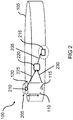
- FIG. 2 shows a schematic representation of a vacuum robot 100 according to an embodiment.
- the sensor housing 110 has a run-up slope 205 in the section 120 for introducing the entry force onto the sensor housing 110 and the elastic element 115.
- the run-up slope 205 is shown here by way of example as a peripheral slope of the section 120.
- an optical environment sensor 210 is rotatably received in the sensor housing 110.
- the environment sensor 210 can be a lidar sensor, for example, which is designed as a rotating point sensor. Navigating and object and environment recognition are advantageous for operating a vacuum robot 100. If the environment sensor 210 is a lidar sensor, an environment of the vacuum robot 100 can be scanned by means of the rotating point sensor and the distance can be determined using a method of light time-of-flight measurement.
- the environment sensor 210 can be designed as a 2D sensor, as a rotating point sensor or as a 3D sensor, as a rotating point sensor with an oscillating mirror.
- the sensor housing 110 can remain in the extended position in order to enable the environment sensor 210 to have an all-round view.
- the device height of the vacuum robot 100 in the region of the rotating environment sensor 210 can be reduced on a case-by-case basis by means of the ramp slope 205, which promotes the introduction of the retracting force onto the sensor housing 110 and the elastic element 115.
- the suction robot 100 also comprises a drive device 215 and a control unit 220.
- the control unit 220 is designed to operate the suction robot 100 or to control it in accordance with a respective operating state.
- control unit 220 is designed to operate suction robot 100 in the navigation state or to operate it in navigation state.
- the sensor housing 110 In the navigation state, the sensor housing 110 is in the extended position.
- the suction robot 100 is designed to move around an environment in the navigation state, the environment map and determine at least one obstacle area.
- the obstacle area represents an area that cannot be reached with the sensor housing 110 in the extended position.
- the control unit 220 is also designed to operate the vacuum robot 100 in a cleaning state.
- the vacuum robot is designed to clean at least the obstacle area in the cleaning state.
- the sensor housing 110 remains in the retracted position.
- the environment sensor 210 provides the control unit 220 with a sensor signal 225.
- the sensor signal 225 represents the mapped environment and the at least one obstacle area.
- the control unit 220 is also designed to read in a position signal 230 that represents a position of the sensor housing 110, for example the extended position or the retracted position.
- the control device 220 is designed to provide a control signal 235 for controlling the drive device 215 using the sensor signal 225 and optionally the position signal 230.
- control unit 220 is also designed to cause the sensor housing 110 to move from the retracted position to the extended position when the cleaning of the determined areas has been completed and additionally or alternatively when an environment that has not yet been mapped in the navigation state is reached.
- control unit 220 is designed to cause sensor housing 110 to move from the extended position into the retracted position.
- FIG 3 shows a schematic representation of a vacuum robot 100 with a charging station 300 according to an embodiment.
- the vacuum robot 100 shown here is similar or corresponds to the vacuum robot from one of the figures mentioned above.
- the charging station 300 has a docking area 305 for docking the vacuum robot 100.
- the docking area 305 is designed to transmit the retracting force to the sensor housing 110 and the elastic element 115 of the vacuum robot.
- the sensor housing 110 can accordingly be retracted and extended by means of the docking area.
- the charging station 300 has a movement device 310 for transmitting the entry force.
- the movement device 310 here comprises a stamp 315 and a magnetic element 320, for example an electromagnet.
- the movement device 310 is designed to activate the magnetic element 320 when the suction robot 100 is docked in order to move the plunger 315 of the movement device 310.
- Magnetic element 320 may be referred to as an active element for depressing sensor housing 110.
- the docking area 305 is also designed to release a locking of the sensor housing 110 in order to enable the sensor housing 110 to move from the retracted position in the direction of the extended position.
- the stamp 315 of the charging station 300 can press on the sensor housing 110 from above in order to press the sensor housing 110 from the extended position into the retracted position.
- the sensor housing 110 can be locked by pressing in beyond the retracted position. By pushing the stamp 315 in again, the sensor housing 110 can be released from the lock.
- the retraction and extension of the sensor housing 110 by means of the movement device 310 can accordingly also be referred to as semi-active retraction and extension, since the sensor housing 110 is pressed upwards into the extended position by the elastic element 115 and, for example, by an electromagnet if necessary is pulled down and held there either by the electromagnet or via a latch.
- the latching can be released again analogously to the push-to-open technology.
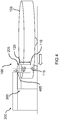
- FIG 4 shows a schematic representation of a vacuum robot 100 with a charging station 300 according to an embodiment.
- the charging station 300 here has an under-slope 405 in the docking area 305.
- the underside slope 405 is shaped in order to transmit the entry force to the sensor housing 110 and the elastic element 115 during the docking process of the vacuum robot 100.
- a mechanical interaction of the underside slope 405 with the sensor housing 110 causes the elastic element 115 to be deformed in order to move the sensor housing 110 from the extended position towards the retracted position.
- the sensor housing 110 here has the run-up slope 205 in the partial section 120, which is advantageous for the insertion of the sensor housing 110 along the lower slope 405.
- the underside slope 405 enables the sensor housing 110 to be retracted passively, insofar as the elastic element 115 is deformed by a mechanical pressure as the retracting force.
- the sensor housing 110 is pressed in the direction of the retracted position.
- FIG. 5 shows a schematic representation of a sensor housing 110 of a vacuum robot according to an embodiment.
- the sensor housing 110 is shown in the extended position.
- the sensor housing here has the run-on slope 205.
- the sensor housing 110 according to the exemplary embodiment shown here has at least one impeller 505 in the section 120 for introducing the retracting force onto the Sensor housing 110 and the elastic member 115.
- the impeller 505 is here arranged, for example, on a surface of the sensor housing 110 above the run-up slope 205 of the section 120.
- the impeller 505 on or on the sensor housing 110 facilitates the passive entry of the sensor housing 110 into the entry position.
- the impeller 505 at the upper end of the beveled sensor housing 110 is arranged in a fixed manner on the section 120 in which, according to one exemplary embodiment, the environment sensor is rotatably received.
- the sensor housing 110 can also have a plurality of run-up wheels 505, which can be arranged on the run-up slope 205, for example.
- the charging station can also have one or more wheels in the docking area in order to avoid scratches on the sensor housing 110 or the charging station and additionally or alternatively a jamming of the sensor housing 110 when it encounters the obstacle 510 or the charging station when entering the Avoid extending position in the direction of the retracted position.
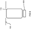
- FIG. 6 shows a schematic representation of a sensor housing 110 of a vacuum robot according to an embodiment.
- the sensor housing 110 shown here is similar or corresponds to the sensor housing described with reference to the previous figures.
- the vacuum robot has a locking unit 605 which is designed to lock the sensor housing 110 in the retracted position.
- the sensor housing 110 is moved by means of the locking unit 605 beyond the retracted position in the direction of a bottom of the robot housing 105, in order to be able to snap back only to the retracted position after the locking.
- the sensor housing 110 is shown as an example in a locking process in which the sensor housing 110 is laterally enclosed by the robot housing 105.
- a height of the sensor housing 110 can correspond, for example, to an outer surface of the robot housing 105, and thus the device height of the robot vacuum cleaner.
- the retraction force is introduced again in order to move the sensor housing 110 towards the bottom of the robot housing 105 by pushing it in again beyond the retracting position. Thereafter, the sensor housing 110 is moved past the retracted position into the extended position by means of the elastic element.
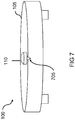
- Figure 7 shows a schematic representation of a vacuum robot 100 according to an embodiment.
- a top view of the vacuum robot 100 is shown.
- the sensor housing 110 protrudes from the robot housing 105 in the extended position.
- the robot housing 105 has a groove 705 adjacent to the sensor housing 110 for introducing the retracting force in order to To sink sensor housing 110 in the robot housing 105.
- the groove 705 can also be referred to as a notch in the housing surface.
- the groove 705 can extend, for example, from an edge region of the robot housing 105 to the sensor housing 110 arranged in the robot housing 105.
- the groove 705 enables the sensor housing 110 to be pressed down below the surface of the robot housing 105 and thus below the housing surface of the robot vacuum cleaner 100.
- the groove 705 is a push-to- open locking, advantageous.
- the groove 705 in the surface of the robot housing 105 can help to press the sensor housing 110 under the surface of the robot housing 105 and thus facilitate or enable snapping.
- a lever or a pin for example, can be inserted into the groove 705 in order to press in the sensor housing 110.
- the lever or pin can be arranged, for example, in the docking area of the charging station of the vacuum robot 100 or on the underside of the docking area.
- FIG 8 shows a schematic representation of a vacuum robot 100 according to an embodiment.
- the environment sensor is accommodated in the sensor housing 110 of the robot vacuum, which is shown by marking a detection area 805 of the environment sensor.
- the detection area 805 is also referred to below as the sensor area 805.
- the environment sensor is protected by the sensor housing 110, as a result of which the sensor housing 110 can also be pressed down in the opening position by the interaction of the run-on slope 205 of the sensor housing 110 with the obstacle 510.
- the beveled sensor housing 110 which is spring-mounted by means of the elastic element 115, is pressed down from the extended position into the retracted position when it encounters the obstacle 510, as shown here by the arrow 810.
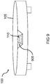
- Figure 9 shows a schematic representation of a vacuum robot 100 according to an embodiment.
- a sensor window 905 is arranged here in the area of the sensor housing 110.
- the sensor housing 110 is shown here by way of example in the retracted position.
- the sensor window 905 is designed to enable the environment sensor accommodated in the sensor housing 110 to have a detection area for the optical detection of the environment even in the retracted position.
- the sensor window 905 can, for example, be cut out of the robot housing 105.
- the sensor window 905 is advantageous in order to enable navigation in the cleaning state of the vacuum robot 100, in which the sensor housing 110 is in the retracted position, by means of the environment sensor accommodated in the sensor housing 110.
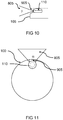
- Figure 10 shows a schematic representation of a sensor area 805 of a vacuum robot according to an embodiment.
- the vertical sensor region 805 is here Detection area ⁇ shown.
- the detection area ⁇ shows an example of the sensor area 805 of the environment sensor received in the sensor housing 110 in the retracted position.
- the detection range ⁇ is made possible by a free cut in the robot housing 105 in the form of the sensor window 805.
- Figure 11 shows a schematic representation of a sensor area 805 of a vacuum robot 100 according to an embodiment.
- a horizontal detection area ⁇ of the environment sensor received in the sensor housing 110 in the retracted position is shown here by way of example as the sensor area 805.
- the detection range ⁇ is made possible by a free cut in the robot housing 105 in the form of the sensor window 905.
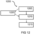
- FIG 12 shows a flowchart of a method 1200 for operating a vacuum robot according to an exemplary embodiment.
- the vacuum robot corresponds or is similar to the vacuum robot from one of the figures described above.
- the method 1200 comprises a step 1205 of operating the vacuum robot in a navigation state and a step 1210 of the operator of the vacuum robot in a cleaning state.
- the sensor housing is in the extended position.
- the vacuum robot is designed to move around an environment in the navigation state, to map the environment and to determine at least one obstacle area.
- the obstacle area represents an area that cannot be reached with the sensor housing in the extended position.
- step 1210 of operating the vacuum robot in the cleaning state the vacuum robot is designed to clean at least the obstacle area.
- the sensor housing remains in the retracted position.
- the method 1200 can also include a step 1215 of causing the sensor housing to move from the retracted position to the extended position when the cleaning of the determined areas is complete. Additionally or alternatively, step 1205 of causing the movement of the sensor housing from the retracted position to the extended position can be carried out if an environment that has not yet been mapped in the navigation state is reached. The step 1215 of bringing about can optionally be carried out after the step 1210 of operating the vacuum robot in the cleaning state.
- the method 1200 may include a step 1220 of causing the sensor housing to move from the extended position to the retracted position.
- the step 1220 of effecting can optionally be carried out after step 1205 of operating the vacuum robot in the navigation state and before step 1210 of operating the reporter in the cleaning state.
- step 1205 is carried out: a map of the surroundings is created and the areas are identified which cannot be reached with the sensor extended, but can be reached with the sensor retracted.
- step 1220 is carried out, the sensor housing and thus the environment sensor are retracted.
- the corresponding areas which can only be reached with the lower device height of the robot vacuum, are specifically cleaned.
- step 1215 is carried out: The sensor housing and thus the sensor are either extended again or remain in the retracted state until an unknown environment is to be cleaned.
Landscapes
- Engineering & Computer Science (AREA)
- Mechanical Engineering (AREA)
- Electric Vacuum Cleaner (AREA)
- Control Of Position, Course, Altitude, Or Attitude Of Moving Bodies (AREA)
Abstract
Description
- Die Erfindung betrifft einen Saugroboter, eine Ladestation für einen Saugroboter und ein Verfahren zum Betreiben eines Saugroboters
- Um ein Hindernis erkennen zu können, kann ein Saugroboter eine Sensoreinrichtung aufweisen, die sowohl vertikal beweglich als auch rotatorisch drehbar ausgeführt ist. Die Bewegung des Sensorgehäuses wird dabei üblicherweise über eine motorische Antriebseinrichtung erzeugt.
- Die
US 9 283 670 B2 - Der Erfindung stellt sich die Aufgabe, einen verbesserten Saugroboter, eine verbesserte Ladestation für einen Saugroboter und ein verbessertes Verfahren zum Betreiben eines Saugroboters zu schaffen.
- Erfindungsgemäß wird diese Aufgabe durch einen Saugroboter, eine Ladestation für einen Saugroboter und ein Verfahren zum Betreiben eines Saugroboters mit den Merkmalen bzw. Schritten der Hauptansprüche gelöst. Vorteilhafte Ausgestaltungen und Weiterbildungen der Erfindung ergeben sich aus den nachfolgenden Unteransprüchen.
- Die mit der Erfindung erreichbaren Vorteile bestehen darin, dass ein Sensorgehäuse des Saugroboters zum Ermöglichen einer Rundumsicht eines Umfeldsensors über eine Geräteoberfläche des Saugroboters hinausragen kann. Um unter niedrige Hindernisse wie ein Sofa oder einen Schrank zu kommen, kann das Sensorgehäuse in den Saugroboter eingezogen werden. Vorteilhafterweise ist es damit einerseits möglich, ein über die Geräteoberfläche hinausragendes Sichtfeld eines in dem Sensorgehäuse aufgenommenen Umfeldsensors zum Navigieren des Saugroboters zu nutzen, und anderseits ist es möglich zum Erreichen und Reinigen von Flächen unter niedrigen Hindernissen das Sensorgehäuse einzuziehen. Dies ermöglicht vorteilhafterweise ein effizientes Navigieren sowie ein effizientes Erreichen und Reinigen trotz Hindernissen und eine kompakte Bauweise des Saugroboters. Das Einziehen des Sensorgehäuses kann ohne motorisierte Antriebseinrichtung erfolgen, und ist dadurch vorteilhafterweise energiesparend.
- Auch wenn der beschriebene Ansatz anhand eines Haushaltgeräts beschrieben wird, kann der hier beschriebene Ansatz entsprechend im Zusammenhang mit einem gewerblichen oder professionellen Gerät, beispielsweise einem medizinischen Gerät eingesetzt werden.
- Ein Saugroboter weist gemäß dem hier beschriebenen Ansatz ein Robotergehäuse, ein Sensorgehäuse und ein elastisches Element auf. Das Sensorgehäuse zum Aufnehmen eines Umfeldsensors für den Saugroboter ist zumindest teilweise in dem Robotergehäuse angeordnet. Das elastische Element ist dazu ausgebildet, das Sensorgehäuse von einer Einfahrposition in Richtung einer Ausfahrposition vorzuspannen. In der Ausfahrposition ragt ein Teilabschnitt des Sensorgehäuses aus dem Robotergehäuse hervor. In der Einfahrposition ist der Teilabschnitt des Sensorgehäuses zumindest teilweise in dem Robotergehäuse angeordnet. Das elastische Element ist durch eine Einfahrkraft verformbar, um eine Bewegung des Sensorgehäuses von der Ausfahrposition in Richtung der Einfahrposition zu ermöglichen. Somit kann ein höhenvariabler Sensor realisiert werden.
- Bei dem elastischen Element kann es sich beispielsweise um eine Feder wie eine Druckfeder oder eine Schraubenzugfeder handeln, oder um ein Elastomer-Element. Die Ausfahrposition kann beispielsweise bei einem Navigieren des Saugroboters in einer unbekannten Umgebung verwendet werden, wenn in dem Sensorgehäuse ein Umfeldsensor, beispielsweise ein Lidar-Sensor aufgenommen ist. Die Einfahrposition kann beispielsweise zum Erreichen eines Bereichs unterhalb eines niedrigen Hindernisses wie einem niedrigen Möbel verwendet werden. In der Ausfahrposition kann das Sensorgehäuse beispielsweise um zehn bis vierzig Prozent einer Gerätehöhe des Saugroboters über eine Oberfläche das Robotergehäuse hervorragen. In der Einfahrposition kann ein oberes Ende des Sensorgehäuses beispielsweise auf der gleichen Höhe wie das Robotergehäuse sein, oder weniger als zehn Prozent der Gerätehöhe über das Robotergehäuse hervorragen. Bei der Einfahrkraft kann es sich beispielsweise um eine mechanische Druckeinwirkung handeln, oder um eine andere Krafteinwirkung, beispielsweise eine magnetische Kraft.
- Gemäß einer Ausführungsform kann das Sensorgehäuse in dem Teilabschnitt eine Auflaufschräge zum Einleiten der Einfahrkraft auf das Sensorgehäuse und das elastische Element aufweisen. Die Auflaufschräge kann beispielsweise eine umlaufende Abschrägung des Teilabschnitts sein. Durch ein Zusammenwirken der Auflaufschräge mit einem Hindernis oder einer entsprechend ausgeformten Struktur, beispielsweise an einer Ladestation des Saugroboters, kann die Einfahrkraft in Form eines mechanischen Drucks auf das Sensorgehäuse ein Verformen des elastischen Elements bewirken, wodurch das Sensorgehäuse in Richtung der Einfahrposition bewegt werden kann. Auf diese Weise kann der Saugroboter beispielsweise an ein Hindernis heranfahren und durch ein Anfahren des Hindernisses das Sensorgehäuse in dir Richtung der Einfahrposition bewegen. Dabei wird das Sensorgehäuse mittels der Auflaufschräge nach unten gedrückt. Vorteilhafterweise kann auf diese Weise eine Beschädigung des Sensorgehäuses durch das Hindernis vermieden werden. Zudem kann das Sensorgehäuse bei einem Unterfahren eines niedrigen Objekts in das Robotergehäuse gedrückt werden, und nach einem Passieren des Hindernisses kann das Sensorgehäuse mittels des elastischen Elements automatisch wieder in die Ausfahrposition bewegt werden, was vorteilhafterweise energiesparend ist.
- Zudem kann das Sensorgehäuse in dem Teilabschnitt gemäß einer Ausführungsform zumindest ein Auflaufrad zum Einleiten der Einfahrkraft auf das Sensorgehäuse und das elastische Element aufweisen. Das Auflaufrad kann beispielsweise feststehend an dem Teilabschnitt angeordnet werden. Der Teilabschnitt kann auch mehrere Auflaufräder aufweisen, die beispielsweise um den Teilabschnitt umlaufend angeordnet sind. Wenn der Teilabschnitt die Auflaufschräge aufweist, kann das Auflaufrad an der Auflaufschräge angeordnet sein. Das Auflaufrad kann bei einem Anfahren des Hindernisses oder der Struktur zum Einleiten der Einfahrkraft in Form eines mechanischen Drucks vorteilhafterweise eine Beschädigung, beispielsweise ein Zerkratzen des Sensorgehäuses verhindern. Zudem kann mittels des Auflaufrads vorteilhafterweise ein Einklemmen des Sensorgehäuses in dem Hindernis oder in der Struktur vorgebeugt werden.
- Der Saugroboter kann gemäß einer Ausführungsform auch eine Arretierungseinheit aufweisen. Die Arretierungseinheit kann dazu ausgebildet sein, das Sensorgehäuse in der Einfahrposition zu arretieren. Dies ist beispielsweise von Vorteil, wenn das Sensorgehäuse während eines Reinigungsvorgangs des Saugroboters unter einem Hindernis wie einem niedrigen Schrank in der Einfahrposition verbleiben soll, um ein Erreichen der Fläche unter dem Hindernis zu ermöglichen und einer Beschädigung des Sensorgehäuses durch das Hindernis zu verhindern.
- Ferner kann das Robotergehäuse des Saugroboters gemäß einer Ausführungsform benachbart zu dem Sensorgehäuse eine Nut zum Einleiten der Einfahrkraft aufweisen, um das Sensorgehäuse in dem Robotergehäuse zu versenken. Die Nut kann beispielsweise um das Sensorgehäuse umlaufend ausgeformt sein. Die Nut kann dazu ausgeformt sein, ansprechend auf die Einfahrkraft eine Bewegung des Sensorgehäuses in eine Arretierungsposition zu ermöglichen, wobei das Sensorgehäuse in der Arretierungsposition innerhalb des Robotergehäuses angeordnet und somit versenkt ist. Die Einfahrposition kann zwischen der Ausfahrposition und der Arretierungsposition angeordnet sein. Dazu kann das Sensorgehäuse mittels der Einfahrkraft beispielweise in das Robotergehäuse versenkt werden, und zum Arretieren in die Einfahrposition zurückschnellen, ähnlich eines Druck-Schnapp-Mechanismus, auch "push-to-open"-Mechanismus (Drücken zum Öffnen-Mechanismus) genannt.
- Auch kann der Saugroboter gemäß einer Ausführungsform einen optischen Umfeldsensor aufweisen, der drehbar in dem Sensorgehäuse aufgenommen ist. Bei dem optischen Umfeldsensor kann es sich beispielsweise um eine Kameraeinrichtung handeln, oder um einen Lidar-Sensor, der beispielsweise als rotierender Punktsensor ausgeführt sein kann, oder als rotierender Punktsensor mit oszillierendem Spiegel. Vorteilhafterweise kann der Saugroboter gemäß dieser Ausführungsform seine Umgebung umfassend und effizient erfassen, wobei durch die Ausformung des Sensorgehäuses und des elastischen Elements eine kompakte Bauweise ermöglicht wird.
- Außerdem kann der Saugroboter gemäß einer Ausführungsform eine Einfahrkrafteinheit aufweisen, die ausgebildet ist, die Einfahrkraft auf das Sensorgehäuse und das elastische Element zu übertragen. Bei der Einfahrkrafteinheit kann es sich beispielsweise um einen Elektromagneten handeln, der von einem Steuergerät des Saugroboters angesteuert werden kann. Dazu kann das Sensorgehäuse beispielsweise ein magnetisches oder ferromagnetisches Element umfassen. Das Sensorgehäuse kann nach einem Aktivieren des Elektromagneten, der beispielsweise in dem Robotergehäuse unter dem Sensorgehäuse angeordnet sein kann, in Richtung der Einfahrposition eingezogen werden. Nach einem Deaktivieren oder erneuten Aktivieren des Elektromagneten kann das Sensorgehäuse mittels des elastischen Elements wieder in Richtung der Ausfahrposition vorgespannt werden. Alternativ kann auch die Ladestation des Saugroboters einen Elektromagneten aufweisen. Vorteilhafterweise ist es somit möglich, das Einfahren und Ausfahren des Sensorgehäuses anzusteuern.
- Mit diesem Ansatz wird auch eine Ladestation für eine Ausführungsform des vorstehend genannten Saugroboters vorgestellt. Die Ladestation weist einen Andockbereich zum Andocken des Saugroboters auf. Der Andockbereich ist ausgebildet, die Einfahrkraft auf das Sensorgehäuse und das elastische Element des Saugroboters zu übertragen. Unter der Ladestation kann beispielsweise eine Station zum automatischen Aufladen eines Energiespeichers des Saugroboters verstanden werden, die von dem Saugroboter bei Bedarf automatisch angefahren werden kann. Die Ladestation kann im Andockbereich zum Übertragen der Einfahrkraft beispielsweise einen beweglichen Hebel aufweisen, der beim Andocken des Saugroboters an die Ladestation das Sensorgehäuse in Richtung der Einfahrposition in das Robotergehäuse des Saugroboters hineindrückt. Vorteilhafterweise ist es somit möglich, Die Einfahrkraft mittels der Ladestation auf das Sensorgehäuse und das elastische Element zu übertragen, was eine kompakte Bauweise ermöglicht.
- Der Andockbereich der Ladestation kann gemäß einer Ausführungsform auch ausgebildet sein, um eine Arretierung des Sensorgehäuses zu lösen, um eine Bewegung des Sensorgehäuses von der Einfahrposition in Richtung der Ausfahrposition zu ermöglichen. Dazu kann die Ladestation beispielsweise einen Stempel aufweisen, der ausgeformt ist, das arretierte Sensorgehäuse hinunterzudrücken, um die Arretierung des Sensorgehäuses zu lösen. Die Arretierung kann in diesem Fall den Druck-Schnapp-Mechanismus, auch "push-to-open" genannt, aufweisen. Vorteilhafterweise kann die Arretierung auf diese Weise einfach gelöst werden.
- Zudem kann der Andockbereich gemäß einer Ausführungsform eine Unterfahrschräge aufweisen, die ausgeformt ist, bei einem Andockvorgang des Saugroboters die Einfahrkraft auf das Sensorgehäuse und das elastische Element zu übertragen. Bei der Unterfahrschräge kann es sich beispielsweise um einen abgeschrägten Bereich handeln. Durch ein mechanisches Zusammenwirken der Unterfahrschräge mit dem Sensorgehäuse kann die Einfahrkraft übertragen werden. Besonders wenn das Sensorgehäuse gemäß einer Ausführungsform eine Auflaufschräge und zusätzlich oder alternativ ein Auflaufrad aufweist, kann die Einfahrkraft auf diese Weise einfach übertragen werden.
- Ferner kann der Andockbereich gemäß einer Ausführungsform eine Bewegungseinrichtung aufweisen, die ausgebildet ist, die Einfahrkraft auf das Sensorgehäuse und das elastische Element des Saugroboters zu übertragen. Bei der Bewegungseinrichtung kann es sich beispielsweise um den Elektromagneten handeln, der ausgebildet ist, das ein ferromagnetisches oder magnetisches Element umfassende Sensorgehäuse durch ein erzeugtes magnetisches Feld zu bewegen. Zusätzlich oder alternativ kann die Ladestation auch ein Bewegungselement zum Herunterdrücken des Sensorgehäuses und Lösen einer Arretierung des Sensorgehäuses aufweisen, das beispielsweise mittels eines elektrischen Signals von der Ladestation angesteuert werden kann.
- Es wird mit diesem Ansatz auch ein Verfahren zum Betreiben einer Ausführungsform des vorstehend genannten Saugroboters vorgestellt. Das Verfahren weist einen Schritt des Betreibens des Saugroboters in einem Navigationszustand und einen Schritt des Betreibens des Saugebotes in einem Reinigungszustand auf. Im Schritt des Betreibens des Saugroboters in dem Navigationszustand ist das Sensorgehäuse in der Ausfahrposition. Der Saugroboter ist ausgebildet, im Navigationszustand eine Umgebung abzufahren, die Umgebung zu kartieren und zumindest einen Hindernisbereich zu ermitteln. Der Hindernisbereich repräsentiert einen Bereich, der nicht mit dem Sensorgehäuse in der Ausfahrposition erreicht werden kann. Im Schritt des Betreibens des Saugroboters in dem Reinigungszustand ist der Saugroboter ausgebildet, zumindest den Hindernisbereich zu reinigen. Das Sensorgehäuse verbleibt dabei in der Einfahrposition. In der Einfahrposition ist das Sensorgehäuse zumindest teilweise von dem Robotergehäuse des Saugroboters umschlossen. Vorteilhafterweise kann somit eine Reinigungsumgebung im Schritt des Betreibens des Saugroboters im Navigationszustand erfasst werden, und anschließend kann ein Bereich im Schritt des Betreibens des Sauggebotes im Reinigungszustand gereinigt werden, der mit dem Sensorgehäuse in Ausfahrposition nicht erreicht werden kann, beispielsweise ein Bereich, der nur bei einer geringen Gerätehöhe des Saugroboters erreicht werden kann.
- Das Verfahren kann gemäß einer Ausführungsform zudem einen Schritt des Herbeiführens einer Bewegung des Sensorgehäuses von der Einfahrposition in die Ausfahrposition umfassen, wenn das Reinigen der ermittelten Bereiche abgeschlossen ist. Zusätzlich oder alternativ kann der Schritt des Herbeiführens der Bewegung des Sensorgehäuses von der Einfuhrposition in die Ausfuhrposition ausgeführt werden, wenn eine noch nicht im Navigationszustand kartierte Umgebung erreicht wird. Vorteilhafterweise kann mit der Navigationszustand bei Bedarf herbeigeführt werden, was ein effizientes Navigieren des Saugroboters und damit ein vorteilhaftes Betreiben des Saugroboters ermöglicht. Der Schritt des Herbeiführens kann optional nach dem Schritt des Betreibens des Saugroboters im Reinigungszustand ausgeführt werden.
- Zudem kann das Verfahren gemäß einer Ausführungsform einen Schritt des Bewirkens einer Bewegung des Sensorgehäuses von der Ausfahrposition in die Einfahrposition aufweisen. Der Schritt des Bewirkens kann optional nach dem Schritt des Betreibens des Saugroboters im Navigationszustand und vor dem Schritt des Betreibens des Reporters im Reinigungszustand ausgeführt werden.
- Der Saugroboter kann gemäß einer Ausführungsform auch eine Antriebseinrichtung ein Steuergerät aufweisen. Das Steuergerät kann dazu ausgebildet sein, die Schritte einer Ausführungsform des vorstehend genannten Verfahrens anzusteuern. Auch durch diese Ausführungsvariante der Erfindung in Form eines Steuergeräts zum Betreiben des Verfahrens kann die der Erfindung zugrunde liegende Aufgabe schnell und effizient gelöst werden.
- Das Steuergerät kann ausgebildet sein, um Eingangssignale einzulesen und unter Verwendung der Eingangssignale Ausgangssignale zu bestimmen und bereitzustellen. Ein Eingangssignal kann beispielsweise ein über eine Eingangsschnittstelle des Steuergeräts einlesbares Sensorsignal darstellen. Ein Ausgangssignal kann ein Steuersignal oder ein Datensignal darstellen, das an einer Ausgangsschnittstelle des Steuergeräts bereitgestellt werden kann. Das Steuergerät kann ausgebildet sein, um die Ausgangssignale unter Verwendung einer in Hardware oder Software umgesetzten Verarbeitungsvorschrift zu bestimmen. Beispielsweise kann das Steuergerät dazu eine Logikschaltung, einen integrierten Schaltkreis oder ein Softwaremodul umfassen und beispielsweise als ein diskretes Bauelement realisiert sein oder von einem diskreten Bauelement umfasst sein.
- Ausführungsbeispiele der Erfindung sind in den Zeichnungen rein schematisch dargestellt und werden nachfolgend näher beschrieben. Es zeigt
- Figur 1
- eine schematische Darstellung eines Saugroboters gemäß einem Ausführungsbeispiel;
- Figur 2
- eine schematische Darstellung eines Saugroboters gemäß einem Ausführungsbeispiel;
- Figur 3
- eine schematische Darstellung eines Saugroboters mit einer Ladestation gemäß einem Ausführungsbeispiel;
- Figur 4
- eine schematische Darstellung eines Saugroboters mit einer Ladestation gemäß einem Ausführungsbeispiel;
- Figur 5
- eine schematische Darstellung eines Sensorgehäuses eines Saugroboters gemäß einem Ausführungsbeispiel;
- Figur 6
- eine schematische Darstellung eines Sensorgehäuses eines Saugroboters gemäß einem Ausführungsbeispiel;
- Figur 7
- eine schematische Darstellung eines Saugroboters gemäß einem Ausführungsbeispiel;
- Figur 8
- eine schematische Darstellung eines Saugroboters gemäß einem Ausführungsbeispiel;
- Figur 9
- eine schematische Darstellung eines Saugroboters gemäß einem Ausführungsbeispiel;
- Figur 10
- eine schematische Darstellung eines Sensorbereichs eines Saugroboters gemäß einem Ausführungsbeispiel;
- Figur 11
- eine schematische Darstellung eines Sensorbereichs eines Saugroboters gemäß einem Ausführungsbeispiel; und
- Figur 12
- ein Ablaufdiagramm eines Verfahrens zum Betreiben eines Saugroboters gemäß einem Ausführungsbeispiel.
- In der nachfolgenden Beschreibung günstiger Ausführungsbeispiele des vorliegenden Ansatzes werden für die in den verschiedenen Figuren dargestellten und ähnlich wirkenden Elemente gleiche oder ähnliche Bezugszeichen verwendet, wobei auf eine wiederholte Beschreibung dieser Elemente verzichtet wird.
-
Figur 1 zeigt eine schematische Darstellung eines Saugroboters 100 gemäß einem Ausführungsbeispiel. Der Saugroboter weist ein Robotergehäuse 105, ein Sensorgehäuse 110 und ein elastisches Element 115 auf. Das Sensorgehäuse 110 zum Aufnehmen eines Umfeldsensors für den Saugroboter 100 ist zumindest teilweise in dem Robotergehäuse 105 angeordnet. Das elastische Element 115 ist dazu ausgebildet, das Sensorgehäuse 110 von einer Einfahrposition in Richtung einer Ausfahrposition vorzuspannen. In der Ausfahrposition ragt ein Teilabschnitt 120 des Sensorgehäuses 110 aus dem Robotergehäuse 105 hervor. In der Einfahrposition ist der Teilabschnitt 120 des Sensorgehäuses 110 zumindest teilweise in dem Robotergehäuse 105 angeordnet. Das elastische Element 115 ist durch eine Einfahrkraft verformbar, um eine Bewegung des Sensorgehäuses 110 von der Ausfahrposition in Richtung der Einfahrposition zu ermöglichen. - Das Sensorgehäuse 110 ist mittels des elastischen Elements 115, hier beispielhaft als Feder gezeigt, gegenüber dem Robotergehäuse 105 beweglich, was durch den Pfeil 125 gezeigt ist. In dem hier gezeigten Ausführungsbeispiel ist das Sensorgehäuse 110 in der Ausfahrposition gezeigt. Zudem ist beispielhaft ein Erfassungsbereich 130 eines in dem Sensorgehäuse 110 aufgenommenen Sensors gezeigt.
- Mittels des elastischen Elements 115 ist es möglich, bei Bedarf eine Höhe des Sensorgehäuses 110 durch ein Einfahren des Sensorgehäuses 110 in die Einfahrposition, die beispielweise einer Höhe einer Geräteoberfläche des Basisgeräts, hier einer Höhe des Robotergehäuses 105, entspricht, zu verringern. Das Sensorgehäuse 110 ist mittels des elastischen Elements 115 federnd gelagert. Wenn das elastische Element 115 eine Feder ist, kann das Sensorgehäuse 110 von der Feder in den maximal ausgefahrenen Zustand in die Ausfahrposition gedrückt werden. Die Lagerung des Sensorgehäuses 110 mittels des elastischen Elements 115 kann auch als bewegliche Lagerung des Sensorgehäuses 110 über eine passive Aktorik bezeichnet werden.
- Zum Herbeiführen der Einfahrposition des Sensorgehäuses 110 kann ein Anwender beispielsweise manuell einen mechanischen Druck als Einfahrkraft auf das Sensorgehäuse 110 ausüben, um das Sensorgehäuse 110 von der Ausfahrposition in die Einfahrposition einzudrücken. Dabei kann das Sensorgehäuse 110 zum Arretieren über die Einfahrposition hinaus bewegt werden, und über einen weiteren mechanischen Druck wieder aus der Arretierung gelöst werden. Dies kann beispielsweise über einen Push-to-Open-Mechanismus realisiert sein, wobei das Lösen durch ein leichtes Drücken (Entlastung) und/oder eine Drehung aus der Arretierung erfolgt. Der Saugroboter 100 kann über ein Display oder eine externe Bedieneinheit den Benutzer darüber informieren, wenn es vorteilhaft ist, das Sensorgehäuse 110 wieder manuell auszufahren. Alternativ kann das elastische Element 115 auch ohne Eingriff des Benutzers verformt werden, um das Sensorgehäuse 110 von der Ausfahrposition in Richtung der Einfahrposition und umgekehrt zu bewegen, wie anhand der nachfolgenden Figuren beschrieben.
- Das Ein- und Ausfahren des Sensorgehäuses 110 von der Ausfahrposition in die Einfahrposition und umgekehrt mittels des elastischen Elements 115 kann auch als passives Ein- und Ausfahren bezeichnet werden. Das Sensorgehäuse 110 wird dazu von dem elastischen Element 115, beispielsweise einer Feder, in der Ausfahrposition gehalten, und das Sensorgehäuse 110 kann zum Einnehmen der Einfahrposition gegen die Federkraft des elastischen Elements 115 verschoben werden, wo es in der Einfahrposition einrasten kann.
-
Figur 2 zeigt eine schematische Darstellung eines Saugroboters 100 gemäß einem Ausführungsbeispiel. Das Sensorgehäuse 110 weist gemäß dem hier gezeigten Ausführungsbeispiel in dem Teilabschnitt 120 eine Auflaufschräge 205 zum Einleiten der Einfahrkraft auf das Sensorgehäuse 110 und das elastische Element 115 auf. Die Auflaufschräge 205 ist hier beispielhaft als umlaufende Abschrägung des Teilabschnitts 120 gezeigt. Bei einem Unterfahren eines Objekts, das niedriger als der Saugroboter 100 mit dem Sensorgehäuse 110 in der Auffahrposition ist, kann das Sensorgehäuse 110 automatisch in das Robotergehäuse 105 eingedrückt werden, ohne dabei zu arretieren. Hat der Saugroboter 100 das unterfahrene Objekt passiert, wird das Sensorgehäuse 110 mittels des elastischen Elements 115 wieder automatisch in die Ausfahrposition bewegt. - In dem Sensorgehäuse 110 ist gemäß dem hier gezeigten Ausführungsbeispiel ein optischer Umfeldsensor 210 drehbar aufgenommen. Der Umfeldsensor 210 kann beispielsweise ein Lidarsensor sein, der als rotierender Punktsensor ausgeführt ist. Navigieren sowie eine Objekt- und Umfelderkennung sind zum Betreiben eines Saugroboters 100 vorteilhaft. Wenn der Umfeldsensor 210 ein Lidar-Sensor ist, kann eine Umgebung des Saugroboters 100 mittels des rotierenden Punktsensors abgetastet und die Entfernung mit einem Verfahren der Licht-Laufzeitmessung (Time-of-Flight) bestimmt werden. Der Umfeldsensor 210 kann dabei als 2D-Sensor, als rotierender Punktsensor oder auch als 3D-Sensor, als rotierender Punktsensor mit oszillierendem Spiegel ausgeführt sein.
- Zum Navigieren mittels des Umfeldsensors 210 kann das Sensorgehäuse 110 in der Ausfahrposition verbleiben, um dem Umfeldsensor 210 eine Rundumsicht zu ermöglichen. Zum Reinigen von Bereichen unter niedrigen Hindernissen, wie einem Sofa oder einem Bett, ist es vorteilhaft, das Sensorgehäuse 110 in Richtung der Einfahrposition zu bewegen. In dem hier gezeigten Ausführungsbeispiel kann die Gerätehöhe des Saugroboters 100 im Bereich des rotierenden Umfeldsensors 210 mittels der Auflaufschräge 205, die ein Einleiten der Einfahrkraft auf das Sensorgehäuse 110 und das elastische Element 115 fördert, fallspezifisch reduziert werden.
- Der Saugroboter 100 umfasst gemäß dem hier gezeigten Ausführungsbeispiel zudem eine Antriebseinrichtung 215 und ein Steuergerät 220. Das Steuergerät 220 ist ausgebildet, den Saugroboter 100 zu betreiben bzw. gemäß einem jeweiligen Betriebszustand anzusteuern. Dazu ist das Steuergerät 220 ausgebildet, den Saugroboter 100 im Navigationszustand zu betreiben bzw. einen Betrieb desselben im Navigationszustand zu bewirken. Im Navigationszustand ist das Sensorgehäuse 110 in der Ausfahrposition. Der Saugroboter 100 ist dazu ausgebildet, im Navigationszustand eine Umgebung abzufahren, die Umgebung zu kartieren und zumindest einen Hindernisbereich zu ermitteln. Der Hindernisbereich repräsentiert einen Bereich, der nicht mit dem Sensorgehäuse 110 in der Ausfahrposition erreicht werden kann. Das Steuergerät 220 ist zudem ausgebildet, den Saugroboter 100 in einem Reinigungszustand zu betreiben. Der Saugroboter ist dazu ausgebildet, in dem Reinigungszustand zumindest den Hindernisbereich zu reinigen. Das Sensorgehäuse 110 verbleibt dabei in der Einfahrposition.
- Gemäß dem hier gezeigten Ausführungsbeispiel stellt der Umfeldsensor 210 dem Steuergerät 220 ein Sensorsignal 225 bereit. Das Sensorsignal 225 repräsentiert die kartierte Umgebung und den zumindest einen Hindernisbereich. Das Steuergerät 220 ist zudem dazu ausgebildet, ein Positionssignal 230 einzulesen, das eine Position des Sensorgehäuses 110 repräsentiert, beispielsweise die Ausfahrposition oder die Einfahrposition. Außerdem ist das Steuergerät 220 ausgebildet, um zum Ansteuern der Antriebseinrichtung 215 unter Verwendung des Sensorsignals 225 und optional des Positionssignals 230 ein Steuersignal 235 bereitzustellen.
- Optional ist das Steuergerät 220 zudem ausgebildet, eine Bewegung des Sensorgehäuses 110 von der Einfahrposition in die Ausfahrposition herbeizuführen, wenn das Reinigen der ermittelten Bereiche abgeschlossen ist und zusätzlich oder alternativ wenn eine noch nicht im Navigationszustand kartierte Umgebung erreicht wird. Gemäß einem weiteren Ausführungsbeispiel ist das Steuergerät 220 ausgebildet, eine Bewegung des Sensorgehäuses 110 von der Ausfahrposition in die Einfahrposition zu bewirken.
-
Figur 3 zeigt eine schematische Darstellung eines Saugroboters 100 mit einer Ladestation 300 gemäß einem Ausführungsbeispiel. Der hier gezeigte Saugroboter 100 ähnelt oder entspricht dem Saugroboter aus einer der vorstehend genannten Figuren. - Die Ladestation 300 weist einen Andockbereich 305 zum Andocken des Saugroboters 100 auf. Der Andockbereich 305 ist ausgebildet, die Einfahrkraft auf das Sensorgehäuse 110 und das elastische Element 115 des Saugroboters zu übertragen. Das Sensorgehäuse 110 kann entsprechend mittels des Andockbereichs ein- und ausgefahren werden.
- Gemäß dem hier gezeigten Ausführungsbeispiel weist die Ladestation 300 zum Übertragen der Einfahrkraft eine Bewegungseinrichtung 310 auf. Die Bewegungseinrichtung 310 umfasst hier einen Stempel 315 und ein Magnetelement 320, beispielsweise einen Elektromagneten. Die Bewegungseinrichtung 310 ist ausgebildet, bei einem Andockvorgang des Saugroboters 100 das Magnetelement 320 zu aktivieren, um den Stempel 315 der Bewegungseinrichtung 310 zu bewegen. Das Magnetelement 320 kann als aktives Element zum Herunterdrücken des Sensorgehäuses 110 bezeichnet werden.
- Der Andockbereich 305 ist gemäß einem Ausführungsbeispiel zudem dazu ausgebildet, eine Arretierung des Sensorgehäuses 110 zu lösen, um eine Bewegung des Sensorgehäuses 110 von der Einfahrposition in Richtung der Ausfahrposition zu ermöglichen. Dazu kann der Stempel 315 der Ladestation 300 von oben auf das Sensorgehäuse 110 drücken, um das Sensorgehäuse 110 von der Ausfahrposition in die Einfahrposition zu drücken. Durch ein Eindrücken über die Einfahrposition hinaus kann ein Arretieren des Sensorgehäuses 110 erfolgen. Durch ein erneutes Hineindrücken des Stempels 315 kann das Sensorgehäuse 110 aus der Arretierung gelöst werden.
- Das Ein- und Ausfahren des Sensorgehäuses 110 mittels der Bewegungseinrichtung 310 kann entsprechend auch als halbaktives Ein- und Ausfahren bezeichnet werden, da das Sensorgehäuse 110 im ausgefahrenen Zustand von dem elastischen Element 115 nach oben in die Ausfahrposition gedrückt wird und beispielsweise von einem Elektromagneten bedarfsweise nach unten gezogen wird und dort entweder vom Elektromagneten oder über eine Verrastung gehalten wird. Durch eine erneute Aktivierung des Elektromagneten mittels des Magnetelements 320 der Bewegungseinrichtung 310 kann die Verrastung analog zu der push-to-open-Technik wieder gelöst werden.
-
Figur 4 zeigt eine schematische Darstellung eines Saugroboters 100 mit einer Ladestation 300 gemäß einem Ausführungsbeispiel. Die Ladestation 300 weist hier im Andockbereich 305 eine Unterfahrschräge 405 auf. Die Unterfahrschräge 405 ist ausgeformt, um bei dem Andockvorgang des Saugroboters 100 die Einfahrkraft auf das Sensorgehäuse 110 und das elastische Element 115 zu übertragen. Durch ein mechanisches Zusammenwirken der Unterfahrschräge 405 mit dem Sensorgehäuse 110 wird ein Verformen des elastischen Elements 115 bewirkt, um das Sensorgehäuse 110 von der Ausfahrposition in Richtung der Einfahrposition zu bewegen. Das Sensorgehäuse 110 weist hier im Teilabschnitt 120 die Auflaufschräge 205 auf, was für das Einfahren des Sensorgehäuses 110 entlang der Unterfahrschräge 405 vorteilhaft ist. - Die Unterfahrschräge 405 ermöglicht ein passives Einfahren des Sensorgehäuses 110, insofern, als das Verformen des elastischen Elements 115 durch einen mechanischen Druck als Einfahrkraft erfolgt. Durch ein Anfahren des Saugroboters 100 an den Andockbereich 305 und ein Unterfahren der Unterfahrschräge 405 wird das Sensorgehäuse 110 in Richtung der Einfahrposition gedrückt.
-
Figur 5 zeigt eine schematische Darstellung eines Sensorgehäuses 110 eines Saugroboters gemäß einem Ausführungsbeispiel. Das Sensorgehäuse 110 ist in der Ausfahrposition gezeigt. In dem Teilabschnitt 120 weist das Sensorgehäuse hier die Auflaufschräge 205 auf. Zudem weist das Sensorgehäuse 110 gemäß dem hier gezeigten Ausführungsbeispiel in dem Teilabschnitt 120 zumindest ein Auflaufrad 505 zum Einleiten der Einfahrkraft auf das Sensorgehäuse 110 und das elastische Element 115 auf. Das Auflaufrad 505 ist hier beispielhaft an einer Oberfläche des Sensorgehäuses 110 oberhalb der Auflaufschräge 205 des Teilabschnitts 120 angeordnet. Bei einem Auftreffen auf ein Hindernis 510 auf der Höhe der Ausfahrposition des Sensorgehäuses 110 wird durch ein Zusammenwirken des Auflaufrads 505 mit dem Hindernis 510 die Einfahrkraft eingeleitet. Das Auflaufrad 505 auf oder an dem Sensorgehäuse 110 erleichtert das passive Einfahren des Sensorgehäuses 110 in die Einfahrposition. Das Auflaufrad 505 am oberen Ende des abgeschrägten Sensorgehäuses 110 ist feststehend am Teilabschnitt 120 angeordnet, in dem gemäß einem Ausführungsbeispiel der Umfeldsensor drehbar aufgenommen ist. Das Sensorgehäuse 110 kann auch mehrere Auflaufräder 505 aufweisen, die beispielsweise an der Auflaufschräge 205 angeordnet sein können. Zusätzlich oder alternativ kann auch die Ladestation in dem Andockbereich ein oder mehrere Räder aufweisen, um Kratzer an dem Sensorgehäuse 110 oder der Ladestation zu vermeiden und zusätzlich oder alternativ ein Klemmen des Sensorgehäuses 110 bei einem Auftreffen auf das Hindernis 510 oder die Ladestation beim Einfahren von der Ausfahrposition in Richtung der Einfahrposition zu vermeiden. -
Figur 6 zeigt eine schematische Darstellung eines Sensorgehäuses 110 eines Saugroboters gemäß einem Ausführungsbeispiel. Das hier gezeigte Sensorgehäuse 110 ähnelt oder entspricht dem anhand der vorhergehenden Figuren beschriebenen Sensorgehäuse. Der Saugroboter weist gemäß dem hier gezeigten Ausführungsbeispiel eine Arretierungseinheit 605 auf, die dazu ausgebildet ist, das Sensorgehäuse 110 in der Einfahrposition zu arretieren. Zum Arretieren wird das Sensorgehäuse 110 mittels der Arretierungseinheit 605 über die Einfahrposition hinaus in Richtung eines Bodens des Robotergehäuses 105 bewegt, um nach dem Arretieren nur bis zu der Einfahrposition zurückschnappen zu können. In dem hier gezeigten Ausführungsbeispiel ist das Sensorgehäuse 110 beispielhaft in einem Arretierungsvorgang gezeigt, in dem das Sensorgehäuse 110 von dem Robotergehäuse 105 seitlich umschlossen wird. In der Einfahrposition kann eine Höhe des Sensorgehäuses 110 beispielsweise einer äußeren Oberfläche des Robotergehäuses 105 entsprechen, und damit der Gerätehöhe des Saugroboters. Zum Lösen der Arretierung wird die Einfahrkraft erneut eingeleitet, um das Sensorgehäuse 110 durch ein erneutes Eindrücken über die Einfahrposition hinaus in Richtung des Bodens des Robotergehäuses 105 zu bewegen. Danach wird das Sensorgehäuse 110 an der Einfahrposition vorbei mittels des elastischen Elements wieder in die Ausfahrposition bewegt. -
Figur 7 zeigt eine schematische Darstellung eines Saugroboters 100 gemäß einem Ausführungsbeispiel. Es ist eine Aufsicht auf den Saugroboter 100 gezeigt. Das Sensorgehäuse 110 ragt in der Ausfahrposition aus dem Robotergehäuse 105 hervor. Das Robotergehäuse 105 weist gemäß dem hier gezeigten Ausführungsbeispiel benachbart zu dem Sensorgehäuse 110 eine Nut 705 zum Einleiten der Einfahrkraft auf, um das Sensorgehäuse 110 in dem Robotergehäuse 105 zu versenken. Die Nut 705 kann auch als Kerbe in der Gehäuseoberfläche bezeichnet werden. Die Nut 705 kann beispielsweise von einem Randbereich des Robotergehäuses 105 bis zu dem in dem Robotergehäuse 105 angeordneten Sensorgehäuse 110 verlaufen. Die Nut 705 ermöglicht ein Herunterdrücken des Sensorgehäuses 110 unter die Oberfläche des Robotergehäuses 105 und damit unter die Gehäuseoberfläche des Saugroboters 100. Wenn der Saugroboter 100 eine Arretierungseinheit aufweist, ist die Nut 705 zum Ermöglichen eines Druck-Schnapp-Mechanismus, einer Push-to-open Verriegelung, vorteilhaft. Die Nut 705 in der Oberfläche des Robotergehäuses 105 kann dabei helfen, das Sensorgehäuse 110 unter die Oberfläche des Robotergehäuses 105 zu drücken und somit das Einrasten erleichtern oder ermöglichen. Dazu kann in die Nut 705 beispielsweise ein Hebel oder ein Stift einfahren, um das Sensorgehäuse 110 einzudrücken. Der Hebel oder Stift kann beispielsweise im Andockbereich der Ladestation des Saugroboters 100 oder an der Unterfahrschräge des Andockbereichs angeordnet sein. -
Figur 8 zeigt eine schematische Darstellung eines Saugroboters 100 gemäß einem Ausführungsbeispiel. In dem Sensorgehäuse 110 des Saugroboters ist hier der Umfeldsensor aufgenommen, was durch eine Markierung eines Erfassungsbereichs 805 des Umfeldsensors gezeigt ist. Der Erfassungsbereich 805 wird im Folgenden auch Sensorbereich 805 genannt. Der Umfeldsensor ist durch das Sensorgehäuse 110 geschützt, wodurch auch hier ein Herunterdrücken des Sensorgehäuses 110 in der Auffahrposition durch ein Zusammenwirken der Auflaufschräge 205 des Sensorgehäuses 110 mit dem Hindernis 510 möglich ist. Dabei wird das abgeschrägte, mittels des elastischen Elements 115 federgelagerte Sensorgehäuse 110 bei einem Auftreffen auf das Hindernis 510 von der Ausfahrposition in die Einfahrposition heruntergedrückt, wie hier durch den Pfeil 810 gezeigt. -
Figur 9 zeigt eine schematische Darstellung eines Saugroboters 100 gemäß einem Ausführungsbeispiel. In dem Robotergehäuse 105 des Saugroboters 100 ist hier in dem Bereich des Sensorgehäuses 110 ein Sensorfenster 905 angeordnet. Das Sensorgehäuse 110 ist hier beispielhaft in der Einfahrposition gezeigt. Das Sensorfenster 905 ist ausgeformt, dem in dem Sensorgehäuse 110 aufgenommenen Umfeldsensor auch in der Einfahrposition einen Erfassungsbereich zum optischen Erfassen des Umfelds zu ermöglichen. Das Sensorfenster 905 kann beispielsweise aus dem Robotergehäuse 105 freigeschnitten sein. Das Sensorfenster 905 ist vorteilhaft, um auch im Reinigungszustand des Saugroboters 100, in dem das Sensorgehäuse 110 in der Einfahrposition ist, ein Navigieren mittels des in dem Sensorgehäuse 110 aufgenommenen Umfeldsensors zu ermöglichen. -
Figur 10 zeigt eine schematische Darstellung eines Sensorbereichs 805 eines Saugroboters gemäß einem Ausführungsbeispiel. Als Sensorbereich 805 ist hier der vertikale Erfassungsbereich β gezeigt. Der Erfassungsbereich β zeigt beispielhaft den Sensorbereich 805 des in dem Sensorgehäuse 110 in der Einfahrposition aufgenommenen Umfeldsensors. Der Erfassungsbereich β wird durch einen Freischnitt in dem Robotergehäuse 105 in Form des Sensorfensters 805 ermöglicht. -
Figur 11 zeigt eine schematische Darstellung eines Sensorbereichs 805 eines Saugroboters 100 gemäß einem Ausführungsbeispiel. Als Sensorbereich 805 ist hier beispielhaft ein horizontaler Erfassungsbereich α des in dem Sensorgehäuse 110 in der Einfahrposition aufgenommenen Umfeldsensors gezeigt. Der Erfassungsbereich α wird durch einen Freischnitt in dem Robotergehäuse 105 in Form des Sensorfensters 905 ermöglicht. -
Figur 12 zeigt ein Ablaufdiagramm eines Verfahrens 1200 zum Betreiben eines Saugroboters gemäß einem Ausführungsbeispiel. Der Saugroboter entspricht oder ähnelt hierbei dem Saugroboter aus einer der vorstehend beschriebenen Figuren. Das Verfahren 1200 umfasst einen Schritt 1205 des Betreibens des Saugroboters in einem Navigationszustand und einen Schritt 1210 des Betreibers des Saugebotes in einem Reinigungszustand auf. Im Schritt 1205 des Betreibens des Saugroboters in dem Navigationszustand ist das Sensorgehäuse in der Ausfahrposition. Der Saugroboter ist ausgebildet, im Navigationszustand eine Umgebung abzufahren, die Umgebung zu kartieren und zumindest eines Hindernisbereichs zu ermitteln. Der Hindernisbereich repräsentiert einen Bereich, der nicht mit dem Sensorgehäuse in der Ausfahrposition erreicht werden kann. Im Schritt 1210 des Betreibens des Saugroboters in dem Reinigungszustand ist der Saugroboter ausgebildet, zumindest den Hindernisbereich zu reinigen. Das Sensorgehäuse verbleibt dabei in der Einfahrposition. - Das Verfahren 1200 kann gemäß einem Ausführungsbeispiel zudem einen Schritt 1215 des Herbeiführens einer Bewegung des Sensorgehäuses von der Einfahrposition in die Ausfahrposition umfassen, wenn das Reinigen der ermittelten Bereiche abgeschlossen ist. Zusätzlich oder alternativ kann der Schritt 1205 des Herbeiführens der Bewegung des Sensorgehäuses von der Einfahrposition in die Ausfahrposition ausgeführt werden, wenn eine noch nicht im Navigationszustand kartierte Umgebung erreicht wird. Der Schritt 1215 des Herbeiführens kann optional nach dem Schritt 1210 des Betreibens des Saugroboters in dem Reinigungszustand ausgeführt werden.
- Zudem kann das Verfahren 1200 gemäß einer Ausführungsform einen Schritt 1220 des Bewirkens einer Bewegung des Sensorgehäuses von der Ausfahrposition in die Einfahrposition aufweisen. Der Schritt 1220 des Bewirkens kann optional nach dem Schritt 1205 des Betreibens des Saugroboters im Navigationszustand und vor dem Schritt 1210 des Betreibens des Reporters im Reinigungszustand ausgeführt werden.
- Im Folgenden wird beispielhaft ein Ablauf des Verfahrens zum Betreiben eines Ausführungsbeispiels des vorstehend genannten Saugroboters beschrieben: In der Einfahrposition des Sensorgehäuses ist der Erfassungsbereich des Umfeldsensors eingeschränkt, insbesondere ist eine Sicht nach hinten blockiert. In einem unbekannten Umfeld könnte dies ein Navigationsergebnis negativ beeinflussen. Daher kann eine erste Reinigungsfahrt des Saugroboters mit ausgefahrenem Sensor erfolgen. Dazu wird der Schritt 1205 ausgeführt: Es wird eine Karte der Umgebung erstellt und es werden die Bereiche identifiziert, die mit ausgefahrenem Sensor nicht, wohl aber mit eingefahrenem Sensor erreicht werden können. Im Anschluss an die erste Reinigungsfahrt wird der Schritt 1220 ausgeführt, das Sensorgehäuse und damit der Umfeldsensor wird eingefahren. Im anschließenden Schritt 1215 werden die entsprechenden Bereiche, die nur mit der geringeren Gerätehöhe des Saugroboters erreicht werden können, gezielt gereinigt. Dies ist möglich, da in einer bekannten Umgebung mit vorhandener Umgebungskarte die verbleibende Navigationsleistung mit dem Blick nach vorne durch das Sensorfenster in dem Robotergehäuse ausreichend ist. Nach der Reinigung dieser Bereiche wird der Schritt 1215 ausgeführt: Das Sensorgehäuse und damit der Sensor wird entweder wieder ausgefahren oder er verbleibt solange in eingefahrenem Zustand, bis eine unbekannte Umgebung gereinigt werden soll.
Claims (15)
- Saugroboter (100) mit folgenden Merkmalen:einem Robotergehäuse (105);einem Sensorgehäuse (110) zum Aufnehmen eines Umfeldsensors (210) für den Saugroboter (100), wobei das Sensorgehäuse (110) zumindest teilweise in dem Robotergehäuse (105) angeordnet ist; undeinem elastischen Element (115), das dazu ausgebildet ist, das Sensorgehäuse (110) von einer Einfahrposition in Richtung einer Ausfahrposition vorzuspannen, wobei in der Ausfahrposition ein Teilabschnitt (120) des Sensorgehäuses (110) aus dem Robotergehäuse (105) hervorragt, wobei in der Einfahrposition der Teilabschnitt (120) des Sensorgehäuses (110) zumindest teilweise in dem Robotergehäuse (105) angeordnet ist, wobei das elastische Element (115) durch eine Einfahrkraft verformbar ist, um eine Bewegung des Sensorgehäuses (110) von der Ausfahrposition in Richtung der Einfahrposition zu ermöglichen.
- Saugroboter (100) gemäß Anspruch 1, wobei das Sensorgehäuse (110) in dem Teilabschnitt (120) eine Auflaufschräge (205) zum Einleiten der Einfahrkraft auf das Sensorgehäuse (110) und das elastische Element (115) aufweist.
- Saugroboter (100) gemäß einem der vorangegangen Ansprüche, wobei das Sensorgehäuse (110) in dem Teilabschnitt (120) zumindest ein Auflaufrad (505) zum Einleiten der Einfahrkraft auf das Sensorgehäuse (110) und das elastische Element (115) aufweist.
- Saugroboter (100) gemäß einem der vorangegangen Ansprüche, mit einer Arretierungseinheit (605), die dazu ausgebildet ist, das Sensorgehäuse (110) in der Einfahrposition zu arretieren.
- Saugroboter (100) gemäß einem der vorangegangen Ansprüche, wobei das Robotergehäuse (105) benachbart zu dem Sensorgehäuse (110) eine Nut (705) zum Einleiten der Einfahrkraft aufweist, um das Sensorgehäuse (110) in dem Robotergehäuse (105) zu versenken.
- Saugroboter (100) gemäß einem der vorangegangen Ansprüche mit einem optischen Umfeldsensor (210), der drehbar in dem Sensorgehäuse (110) aufgenommen ist.
- Saugroboter (100) gemäß einem der vorangegangen Ansprüche mit einer Einfahrkrafteinheit, die ausgebildet ist, die Einfahrkraft auf das Sensorgehäuse (110) und das elastische Element (115) zu übertragen.
- Saugroboter (100) gemäß einem der vorangegangen Ansprüche mit einer Antriebseinrichtung (215) und mit einem Steuergerät (220), das dazu ausgebildet ist, die Schritte eines Verfahrens (1200) gemäß einem der Ansprüche 13 bis 15 anzusteuern.
- Ladestation (300) für einen Saugroboter (100) gemäß einem der vorangegangenen Ansprüche, wobei die Ladestation (300) einen Andockbereich (305) zum Andocken des Saugroboters (100) aufweist, wobei der Andockbereich (305) ausgebildet ist, die Einfahrkraft auf das Sensorgehäuse (110) und das elastische Element (115) des Saugroboters (100) zu übertragen.
- Ladestation (300) gemäß Anspruch 9, wobei der Andockbereich (305) ausgebildet ist, um eine Arretierung des Sensorgehäuses (110) zu lösen, um eine Bewegung des Sensorgehäuses (110) von der Einfahrposition in Richtung der Ausfahrposition zu ermöglichen.
- Ladestation (300) gemäß einem der Ansprüche 9 bis 10, wobei der Andockbereich (305) eine Unterfahrschräge (405) aufweist, die ausgeformt ist, bei einem Andockvorgang des Saugroboters (100) die Einfahrkraft auf das Sensorgehäuse (110) und das elastische Element (115) zu übertragen.
- Ladestation (300) gemäß einem der Ansprüche 9 bis 11, wobei der Andockbereich (305) eine Bewegungseinrichtung (310) aufweist, die ausgebildet ist, die Einfahrkraft auf das Sensorgehäuse (110) und das elastische Element (115) des Saugroboters (100) zu übertragen.
- Verfahren (1200) zum Betreiben eines Saugroboters (100) gemäß einem der vorangegangen Ansprüche 1 bis 8, wobei das Verfahren (1200) folgende Schritte aufweist:Betreiben (1205) des Saugroboters (100) in einem Navigationszustand, wobei das Sensorgehäuse (110) im Navigationszustand in der Ausfahrposition ist, wobei der Saugroboter (100) ausgebildet ist, im Navigationszustand eine Umgebung abzufahren, die Umgebung zu kartieren und zumindest einen Hindernisbereich zu ermitteln, wobei der Hindernisbereich einen Bereich repräsentiert, der nicht mit dem Sensorgehäuse (110) in der Ausfahrposition erreicht werden kann; undBetreiben des Saugroboters (100) in einem Reinigungszustand, wobei der Saugroboter (100) ausgebildet ist, im Reinigungszustand zumindest den Hindernisbereich zu reinigen, wobei das Sensorgehäuse (110) in der Einfahrposition verbleibt.
- Verfahren (1200) gemäß Anspruch 13, mit einem Schritt (1215) des Herbeiführens einer Bewegung des Sensorgehäuses (110) von der Einfahrposition in die Ausfahrposition, wenn das Reinigen der ermittelten Bereiche abgeschlossen ist und/oder wenn eine noch nicht im Navigationszustand kartierte Umgebung erreicht wird.
- Verfahren (1200) gemäß einem der Ansprüche 13 bis 14, mit einem Schritt (1220) des Bewirkens einer Bewegung des Sensorgehäuses (110) von der Ausfahrposition in die Einfahrposition.
Applications Claiming Priority (1)
| Application Number | Priority Date | Filing Date | Title |
|---|---|---|---|
| DE102018117191.9A DE102018117191A1 (de) | 2018-07-17 | 2018-07-17 | Saugroboter, Ladestation für einen Saugroboter und Verfahren zum Betreiben eines Saugroboters |
Publications (2)
| Publication Number | Publication Date |
|---|---|
| EP3597090A1 true EP3597090A1 (de) | 2020-01-22 |
| EP3597090B1 EP3597090B1 (de) | 2020-09-16 |
Family
ID=66912690
Family Applications (1)
| Application Number | Title | Priority Date | Filing Date |
|---|---|---|---|
| EP19180530.8A Active EP3597090B1 (de) | 2018-07-17 | 2019-06-17 | Saugroboter, ladestation für einen saugroboter und verfahren zum betreiben eines saugroboters |
Country Status (2)
| Country | Link |
|---|---|
| EP (1) | EP3597090B1 (de) |
| DE (1) | DE102018117191A1 (de) |
Cited By (10)
| Publication number | Priority date | Publication date | Assignee | Title |
|---|---|---|---|---|
| CN114504282A (zh) * | 2022-01-14 | 2022-05-17 | 科沃斯机器人股份有限公司 | 清洁基站、清洁设备及清洁系统 |
| US20230333551A1 (en) * | 2016-01-15 | 2023-10-19 | Irobot Corporation | Autonomous monitoring robot systems |
| US12296694B2 (en) | 2021-03-10 | 2025-05-13 | Techtronic Cordless Gp | Lawnmowers |
| CN120000111A (zh) * | 2025-01-27 | 2025-05-16 | 北京石头创新科技有限公司 | 升降控制方法、系统、电子设备及存储介质 |
| US12369509B2 (en) | 2022-07-19 | 2025-07-29 | Techtronic Cordless Gp | Display for controlling robotic tool |
| US12425197B2 (en) | 2022-07-29 | 2025-09-23 | Techtronic Cordless Gp | Generation of a cryptography key for a robotic garden tool |
| US12443180B2 (en) | 2021-11-10 | 2025-10-14 | Techtronic Cordless Gp | Robotic lawn mowers |
| US12472611B2 (en) | 2022-05-31 | 2025-11-18 | Techtronic Cordless Gp | Peg driver |
| US12510892B2 (en) | 2022-04-28 | 2025-12-30 | Techtronic Cordless Gp | Creation of a virtual boundary for a robotic garden tool |
| US12564130B2 (en) | 2022-01-31 | 2026-03-03 | Techtronic Cordless Gp | Robotic garden tool |
Families Citing this family (3)
| Publication number | Priority date | Publication date | Assignee | Title |
|---|---|---|---|---|
| DE102021202514B4 (de) | 2021-03-15 | 2023-03-02 | BSH Hausgeräte GmbH | Mobiles, selbstfahrendes Gerät |
| CN116661432A (zh) * | 2022-02-21 | 2023-08-29 | 追觅创新科技(苏州)有限公司 | 自移动设备、自移动设备的控制方法、设备及存储介质 |
| CN116919258A (zh) * | 2022-04-08 | 2023-10-24 | 北京石头世纪科技股份有限公司 | 清洁机器人 |
Citations (3)
| Publication number | Priority date | Publication date | Assignee | Title |
|---|---|---|---|---|
| DE102011053975A1 (de) * | 2010-10-05 | 2012-04-05 | Vorwerk & Co. Interholding Gmbh | Hinderniserkennung für ein selbsttätig verfahrbares Gerät |
| EP2774523A2 (de) * | 2013-03-05 | 2014-09-10 | LG Electronics, Inc. | Reinigungsroboter |
| EP3047773A1 (de) * | 2015-01-23 | 2016-07-27 | Samsung Electronics Co., Ltd. | Reinigungsroboter und steuerungsverfahren dafür |
-
2018
- 2018-07-17 DE DE102018117191.9A patent/DE102018117191A1/de not_active Withdrawn
-
2019
- 2019-06-17 EP EP19180530.8A patent/EP3597090B1/de active Active
Patent Citations (4)
| Publication number | Priority date | Publication date | Assignee | Title |
|---|---|---|---|---|
| DE102011053975A1 (de) * | 2010-10-05 | 2012-04-05 | Vorwerk & Co. Interholding Gmbh | Hinderniserkennung für ein selbsttätig verfahrbares Gerät |
| EP2774523A2 (de) * | 2013-03-05 | 2014-09-10 | LG Electronics, Inc. | Reinigungsroboter |
| US9283670B2 (en) | 2013-03-05 | 2016-03-15 | Lg Electronics Inc. | Robot cleaner |
| EP3047773A1 (de) * | 2015-01-23 | 2016-07-27 | Samsung Electronics Co., Ltd. | Reinigungsroboter und steuerungsverfahren dafür |
Cited By (11)
| Publication number | Priority date | Publication date | Assignee | Title |
|---|---|---|---|---|
| US20230333551A1 (en) * | 2016-01-15 | 2023-10-19 | Irobot Corporation | Autonomous monitoring robot systems |
| US12443181B2 (en) * | 2016-01-15 | 2025-10-14 | Irobot Corporation | Autonomous monitoring robot systems |
| US12296694B2 (en) | 2021-03-10 | 2025-05-13 | Techtronic Cordless Gp | Lawnmowers |
| US12443180B2 (en) | 2021-11-10 | 2025-10-14 | Techtronic Cordless Gp | Robotic lawn mowers |
| CN114504282A (zh) * | 2022-01-14 | 2022-05-17 | 科沃斯机器人股份有限公司 | 清洁基站、清洁设备及清洁系统 |
| US12564130B2 (en) | 2022-01-31 | 2026-03-03 | Techtronic Cordless Gp | Robotic garden tool |
| US12510892B2 (en) | 2022-04-28 | 2025-12-30 | Techtronic Cordless Gp | Creation of a virtual boundary for a robotic garden tool |
| US12472611B2 (en) | 2022-05-31 | 2025-11-18 | Techtronic Cordless Gp | Peg driver |
| US12369509B2 (en) | 2022-07-19 | 2025-07-29 | Techtronic Cordless Gp | Display for controlling robotic tool |
| US12425197B2 (en) | 2022-07-29 | 2025-09-23 | Techtronic Cordless Gp | Generation of a cryptography key for a robotic garden tool |
| CN120000111A (zh) * | 2025-01-27 | 2025-05-16 | 北京石头创新科技有限公司 | 升降控制方法、系统、电子设备及存储介质 |
Also Published As
| Publication number | Publication date |
|---|---|
| EP3597090B1 (de) | 2020-09-16 |
| DE102018117191A1 (de) | 2020-01-23 |
Similar Documents
| Publication | Publication Date | Title |
|---|---|---|
| EP3597090B1 (de) | Saugroboter, ladestation für einen saugroboter und verfahren zum betreiben eines saugroboters | |
| DE202009010809U1 (de) | Mobile Robotervorrichtung mit einem Aufprallsensor | |
| EP3335606B1 (de) | Selbsttätig fortbewegbares reinigungsgerät | |
| EP3100659B1 (de) | Reinigungseinrichtung für ein selbstfahrendes bodenbearbeitungsgerät | |
| EP2367164A2 (de) | Tafelanordnung | |
| DE102016222853B4 (de) | Koppeleinrichtung zum Herstellen und Trennen einer energieübertragenden Steckverbindung, und Energiezuführsystem mit einer solchen Koppeleinrichtung | |
| EP3725202B1 (de) | Sich selbsttätig fortbewegender saugroboter sowie system aus einem sich selbsttätig fortbewegenden saugroboter und einem externen saugreinigungsgerät | |
| WO2019029983A1 (de) | Fernsteuerungsanordnung | |
| DE102022211684A1 (de) | Verfahren zum Betrieb eines mobilen, selbstfahrenden Geräts | |
| DE3305897A1 (de) | Plattenantrieb | |
| DE3818092A1 (de) | Mehrpolige steckverbindung | |
| EP2986264B1 (de) | Verfahren und vorrichtung zum bedienen eines mobilen operationstischs | |
| DE102018117192A1 (de) | Saugroboter, Ladestation für einen Saugroboter und Verfahren zum Betreiben eines Saugroboters | |
| EP3527118B1 (de) | Reinigungsroboter | |
| DE102015207244A1 (de) | Haltevorrichtung zur Halterung eines Mobilgeräts, insbesondere in einem Fahrzeug | |
| DE102023205527B3 (de) | Verfahren zum Steuern eines mobilen, selbstfahrenden Geräts | |
| EP2781429A1 (de) | Fahrzeug und Einkaufswagen | |
| DE102020127678A1 (de) | Arretierungsvorrichtung | |
| DE102016013774A1 (de) | Ladevorrichtung und Verfahren zum Laden eines elektrischen Energiespeichers eines Kraftfahrzeugs und Kraftfahrzeug | |
| EP2000069B1 (de) | Reinigungswagen | |
| EP1925248B1 (de) | Gerätestiel | |
| EP4212077B1 (de) | Verfahren zum steuern eines sich autonom fortbewegenden bo-denreinigungsgeräts, computerprogrammprodukt sowie boden-reinigungsgerät zur durchführung des verfahrens | |
| DE3723144A1 (de) | Zwischenradmechanismus | |
| EP3479751B1 (de) | Ladevorrichtung für haushaltsgerät und haushaltsgerät | |
| DE102019209416A1 (de) | Fahrzeug mit Linearaktuator |
Legal Events
| Date | Code | Title | Description |
|---|---|---|---|
| PUAI | Public reference made under article 153(3) epc to a published international application that has entered the european phase |
Free format text: ORIGINAL CODE: 0009012 |
|
| STAA | Information on the status of an ep patent application or granted ep patent |
Free format text: STATUS: THE APPLICATION HAS BEEN PUBLISHED |
|
| STAA | Information on the status of an ep patent application or granted ep patent |
Free format text: STATUS: REQUEST FOR EXAMINATION WAS MADE |
|
| AK | Designated contracting states |
Kind code of ref document: A1 Designated state(s): AL AT BE BG CH CY CZ DE DK EE ES FI FR GB GR HR HU IE IS IT LI LT LU LV MC MK MT NL NO PL PT RO RS SE SI SK SM TR |
|
| AX | Request for extension of the european patent |
Extension state: BA ME |
|
| 17P | Request for examination filed |
Effective date: 20200113 |
|
| RBV | Designated contracting states (corrected) |
Designated state(s): AL AT BE BG CH CY CZ DE DK EE ES FI FR GB GR HR HU IE IS IT LI LT LU LV MC MK MT NL NO PL PT RO RS SE SI SK SM TR |
|
| GRAP | Despatch of communication of intention to grant a patent |
Free format text: ORIGINAL CODE: EPIDOSNIGR1 |
|
| STAA | Information on the status of an ep patent application or granted ep patent |
Free format text: STATUS: GRANT OF PATENT IS INTENDED |
|
| INTG | Intention to grant announced |
Effective date: 20200618 |
|
| GRAS | Grant fee paid |
Free format text: ORIGINAL CODE: EPIDOSNIGR3 |
|
| GRAA | (expected) grant |
Free format text: ORIGINAL CODE: 0009210 |
|
| STAA | Information on the status of an ep patent application or granted ep patent |
Free format text: STATUS: THE PATENT HAS BEEN GRANTED |
|
| AK | Designated contracting states |
Kind code of ref document: B1 Designated state(s): AL AT BE BG CH CY CZ DE DK EE ES FI FR GB GR HR HU IE IS IT LI LT LU LV MC MK MT NL NO PL PT RO RS SE SI SK SM TR |
|
| REG | Reference to a national code |
Ref country code: GB Ref legal event code: FG4D Free format text: NOT ENGLISH |
|
| REG | Reference to a national code |
Ref country code: DE Ref legal event code: R084 Ref document number: 502019000219 Country of ref document: DE |
|
| REG | Reference to a national code |
Ref country code: CH Ref legal event code: EP |
|
| REG | Reference to a national code |
Ref country code: DE Ref legal event code: R096 Ref document number: 502019000219 Country of ref document: DE |
|
| REG | Reference to a national code |
Ref country code: IE Ref legal event code: FG4D Free format text: LANGUAGE OF EP DOCUMENT: GERMAN |
|
| REG | Reference to a national code |
Ref country code: AT Ref legal event code: REF Ref document number: 1313366 Country of ref document: AT Kind code of ref document: T Effective date: 20201015 |
|
| REG | Reference to a national code |
Ref country code: GB Ref legal event code: 746 Effective date: 20201013 |
|
| PG25 | Lapsed in a contracting state [announced via postgrant information from national office to epo] |
Ref country code: FI Free format text: LAPSE BECAUSE OF FAILURE TO SUBMIT A TRANSLATION OF THE DESCRIPTION OR TO PAY THE FEE WITHIN THE PRESCRIBED TIME-LIMIT Effective date: 20200916 Ref country code: NO Free format text: LAPSE BECAUSE OF FAILURE TO SUBMIT A TRANSLATION OF THE DESCRIPTION OR TO PAY THE FEE WITHIN THE PRESCRIBED TIME-LIMIT Effective date: 20201216 Ref country code: GR Free format text: LAPSE BECAUSE OF FAILURE TO SUBMIT A TRANSLATION OF THE DESCRIPTION OR TO PAY THE FEE WITHIN THE PRESCRIBED TIME-LIMIT Effective date: 20201217 Ref country code: BG Free format text: LAPSE BECAUSE OF FAILURE TO SUBMIT A TRANSLATION OF THE DESCRIPTION OR TO PAY THE FEE WITHIN THE PRESCRIBED TIME-LIMIT Effective date: 20201216 Ref country code: SE Free format text: LAPSE BECAUSE OF FAILURE TO SUBMIT A TRANSLATION OF THE DESCRIPTION OR TO PAY THE FEE WITHIN THE PRESCRIBED TIME-LIMIT Effective date: 20200916 Ref country code: HR Free format text: LAPSE BECAUSE OF FAILURE TO SUBMIT A TRANSLATION OF THE DESCRIPTION OR TO PAY THE FEE WITHIN THE PRESCRIBED TIME-LIMIT Effective date: 20200916 |
|
| REG | Reference to a national code |
Ref country code: NL Ref legal event code: MP Effective date: 20200916 |
|
| PG25 | Lapsed in a contracting state [announced via postgrant information from national office to epo] |
Ref country code: LV Free format text: LAPSE BECAUSE OF FAILURE TO SUBMIT A TRANSLATION OF THE DESCRIPTION OR TO PAY THE FEE WITHIN THE PRESCRIBED TIME-LIMIT Effective date: 20200916 Ref country code: RS Free format text: LAPSE BECAUSE OF FAILURE TO SUBMIT A TRANSLATION OF THE DESCRIPTION OR TO PAY THE FEE WITHIN THE PRESCRIBED TIME-LIMIT Effective date: 20200916 |
|
| REG | Reference to a national code |
Ref country code: LT Ref legal event code: MG4D |
|
| PG25 | Lapsed in a contracting state [announced via postgrant information from national office to epo] |
Ref country code: RO Free format text: LAPSE BECAUSE OF FAILURE TO SUBMIT A TRANSLATION OF THE DESCRIPTION OR TO PAY THE FEE WITHIN THE PRESCRIBED TIME-LIMIT Effective date: 20200916 Ref country code: PT Free format text: LAPSE BECAUSE OF FAILURE TO SUBMIT A TRANSLATION OF THE DESCRIPTION OR TO PAY THE FEE WITHIN THE PRESCRIBED TIME-LIMIT Effective date: 20210118 Ref country code: CZ Free format text: LAPSE BECAUSE OF FAILURE TO SUBMIT A TRANSLATION OF THE DESCRIPTION OR TO PAY THE FEE WITHIN THE PRESCRIBED TIME-LIMIT Effective date: 20200916 Ref country code: EE Free format text: LAPSE BECAUSE OF FAILURE TO SUBMIT A TRANSLATION OF THE DESCRIPTION OR TO PAY THE FEE WITHIN THE PRESCRIBED TIME-LIMIT Effective date: 20200916 Ref country code: LT Free format text: LAPSE BECAUSE OF FAILURE TO SUBMIT A TRANSLATION OF THE DESCRIPTION OR TO PAY THE FEE WITHIN THE PRESCRIBED TIME-LIMIT Effective date: 20200916 Ref country code: SM Free format text: LAPSE BECAUSE OF FAILURE TO SUBMIT A TRANSLATION OF THE DESCRIPTION OR TO PAY THE FEE WITHIN THE PRESCRIBED TIME-LIMIT Effective date: 20200916 |
|
| PG25 | Lapsed in a contracting state [announced via postgrant information from national office to epo] |
Ref country code: PL Free format text: LAPSE BECAUSE OF FAILURE TO SUBMIT A TRANSLATION OF THE DESCRIPTION OR TO PAY THE FEE WITHIN THE PRESCRIBED TIME-LIMIT Effective date: 20200916 Ref country code: IS Free format text: LAPSE BECAUSE OF FAILURE TO SUBMIT A TRANSLATION OF THE DESCRIPTION OR TO PAY THE FEE WITHIN THE PRESCRIBED TIME-LIMIT Effective date: 20210116 Ref country code: AL Free format text: LAPSE BECAUSE OF FAILURE TO SUBMIT A TRANSLATION OF THE DESCRIPTION OR TO PAY THE FEE WITHIN THE PRESCRIBED TIME-LIMIT Effective date: 20200916 Ref country code: ES Free format text: LAPSE BECAUSE OF FAILURE TO SUBMIT A TRANSLATION OF THE DESCRIPTION OR TO PAY THE FEE WITHIN THE PRESCRIBED TIME-LIMIT Effective date: 20200916 |
|
| REG | Reference to a national code |
Ref country code: DE Ref legal event code: R097 Ref document number: 502019000219 Country of ref document: DE |
|
| PG25 | Lapsed in a contracting state [announced via postgrant information from national office to epo] |
Ref country code: SK Free format text: LAPSE BECAUSE OF FAILURE TO SUBMIT A TRANSLATION OF THE DESCRIPTION OR TO PAY THE FEE WITHIN THE PRESCRIBED TIME-LIMIT Effective date: 20200916 |
|
| PLBE | No opposition filed within time limit |
Free format text: ORIGINAL CODE: 0009261 |
|
| STAA | Information on the status of an ep patent application or granted ep patent |
Free format text: STATUS: NO OPPOSITION FILED WITHIN TIME LIMIT |
|
| 26N | No opposition filed |
Effective date: 20210617 |
|
| PG25 | Lapsed in a contracting state [announced via postgrant information from national office to epo] |
Ref country code: DK Free format text: LAPSE BECAUSE OF FAILURE TO SUBMIT A TRANSLATION OF THE DESCRIPTION OR TO PAY THE FEE WITHIN THE PRESCRIBED TIME-LIMIT Effective date: 20200916 |
|
| PG25 | Lapsed in a contracting state [announced via postgrant information from national office to epo] |
Ref country code: IT Free format text: LAPSE BECAUSE OF FAILURE TO SUBMIT A TRANSLATION OF THE DESCRIPTION OR TO PAY THE FEE WITHIN THE PRESCRIBED TIME-LIMIT Effective date: 20200916 |
|
| PG25 | Lapsed in a contracting state [announced via postgrant information from national office to epo] |
Ref country code: MC Free format text: LAPSE BECAUSE OF FAILURE TO SUBMIT A TRANSLATION OF THE DESCRIPTION OR TO PAY THE FEE WITHIN THE PRESCRIBED TIME-LIMIT Effective date: 20200916 |
|
| REG | Reference to a national code |
Ref country code: BE Ref legal event code: MM Effective date: 20210630 |
|
| PG25 | Lapsed in a contracting state [announced via postgrant information from national office to epo] |
Ref country code: LU Free format text: LAPSE BECAUSE OF NON-PAYMENT OF DUE FEES Effective date: 20210617 |
|
| PG25 | Lapsed in a contracting state [announced via postgrant information from national office to epo] |
Ref country code: IE Free format text: LAPSE BECAUSE OF NON-PAYMENT OF DUE FEES Effective date: 20210617 |
|
| PG25 | Lapsed in a contracting state [announced via postgrant information from national office to epo] |
Ref country code: BE Free format text: LAPSE BECAUSE OF NON-PAYMENT OF DUE FEES Effective date: 20210630 |
|
| REG | Reference to a national code |
Ref country code: CH Ref legal event code: PL |
|
| PG25 | Lapsed in a contracting state [announced via postgrant information from national office to epo] |
Ref country code: LI Free format text: LAPSE BECAUSE OF NON-PAYMENT OF DUE FEES Effective date: 20220630 Ref country code: CH Free format text: LAPSE BECAUSE OF NON-PAYMENT OF DUE FEES Effective date: 20220630 |
|
| PG25 | Lapsed in a contracting state [announced via postgrant information from national office to epo] |
Ref country code: NL Free format text: LAPSE BECAUSE OF NON-PAYMENT OF DUE FEES Effective date: 20200923 Ref country code: CY Free format text: LAPSE BECAUSE OF FAILURE TO SUBMIT A TRANSLATION OF THE DESCRIPTION OR TO PAY THE FEE WITHIN THE PRESCRIBED TIME-LIMIT Effective date: 20200916 |
|
| P01 | Opt-out of the competence of the unified patent court (upc) registered |
Effective date: 20230528 |
|
| PG25 | Lapsed in a contracting state [announced via postgrant information from national office to epo] |
Ref country code: HU Free format text: LAPSE BECAUSE OF FAILURE TO SUBMIT A TRANSLATION OF THE DESCRIPTION OR TO PAY THE FEE WITHIN THE PRESCRIBED TIME-LIMIT; INVALID AB INITIO Effective date: 20190617 |
|
| PG25 | Lapsed in a contracting state [announced via postgrant information from national office to epo] |
Ref country code: SI Free format text: LAPSE BECAUSE OF FAILURE TO SUBMIT A TRANSLATION OF THE DESCRIPTION OR TO PAY THE FEE WITHIN THE PRESCRIBED TIME-LIMIT Effective date: 20200916 |
|
| PG25 | Lapsed in a contracting state [announced via postgrant information from national office to epo] |
Ref country code: MK Free format text: LAPSE BECAUSE OF FAILURE TO SUBMIT A TRANSLATION OF THE DESCRIPTION OR TO PAY THE FEE WITHIN THE PRESCRIBED TIME-LIMIT Effective date: 20200916 |
|
| PG25 | Lapsed in a contracting state [announced via postgrant information from national office to epo] |
Ref country code: TR Free format text: LAPSE BECAUSE OF FAILURE TO SUBMIT A TRANSLATION OF THE DESCRIPTION OR TO PAY THE FEE WITHIN THE PRESCRIBED TIME-LIMIT Effective date: 20200916 |
|
| PG25 | Lapsed in a contracting state [announced via postgrant information from national office to epo] |
Ref country code: MT Free format text: LAPSE BECAUSE OF FAILURE TO SUBMIT A TRANSLATION OF THE DESCRIPTION OR TO PAY THE FEE WITHIN THE PRESCRIBED TIME-LIMIT Effective date: 20200916 |
|
| PGFP | Annual fee paid to national office [announced via postgrant information from national office to epo] |
Ref country code: DE Payment date: 20250630 Year of fee payment: 7 |
|
| PGFP | Annual fee paid to national office [announced via postgrant information from national office to epo] |
Ref country code: GB Payment date: 20250617 Year of fee payment: 7 |
|
| PGFP | Annual fee paid to national office [announced via postgrant information from national office to epo] |
Ref country code: FR Payment date: 20250624 Year of fee payment: 7 |
|
| REG | Reference to a national code |
Ref country code: AT Ref legal event code: MM01 Ref document number: 1313366 Country of ref document: AT Kind code of ref document: T Effective date: 20240617 |
|
| PG25 | Lapsed in a contracting state [announced via postgrant information from national office to epo] |
Ref country code: AT Free format text: LAPSE BECAUSE OF NON-PAYMENT OF DUE FEES Effective date: 20240617 |
|
| PGFP | Annual fee paid to national office [announced via postgrant information from national office to epo] |
Ref country code: AT Payment date: 20260410 Year of fee payment: 5 |