EP3596360B1 - Disengageable speed-reducing unit - Google Patents
Disengageable speed-reducing unit Download PDFInfo
- Publication number
- EP3596360B1 EP3596360B1 EP18727854.4A EP18727854A EP3596360B1 EP 3596360 B1 EP3596360 B1 EP 3596360B1 EP 18727854 A EP18727854 A EP 18727854A EP 3596360 B1 EP3596360 B1 EP 3596360B1
- Authority
- EP
- European Patent Office
- Prior art keywords
- ring gear
- speed reducer
- ring
- gear
- coupled
- Prior art date
- Legal status (The legal status is an assumption and is not a legal conclusion. Google has not performed a legal analysis and makes no representation as to the accuracy of the status listed.)
- Active
Links
Images


Classifications
-
- F—MECHANICAL ENGINEERING; LIGHTING; HEATING; WEAPONS; BLASTING
- F02—COMBUSTION ENGINES; HOT-GAS OR COMBUSTION-PRODUCT ENGINE PLANTS
- F02C—GAS-TURBINE PLANTS; AIR INTAKES FOR JET-PROPULSION PLANTS; CONTROLLING FUEL SUPPLY IN AIR-BREATHING JET-PROPULSION PLANTS
- F02C7/00—Features, components parts, details or accessories, not provided for in, or of interest apart form groups F02C1/00 - F02C6/00; Air intakes for jet-propulsion plants
- F02C7/36—Power transmission arrangements between the different shafts of the gas turbine plant, or between the gas-turbine plant and the power user
-
- F—MECHANICAL ENGINEERING; LIGHTING; HEATING; WEAPONS; BLASTING
- F16—ENGINEERING ELEMENTS AND UNITS; GENERAL MEASURES FOR PRODUCING AND MAINTAINING EFFECTIVE FUNCTIONING OF MACHINES OR INSTALLATIONS; THERMAL INSULATION IN GENERAL
- F16H—GEARING
- F16H55/00—Elements with teeth or friction surfaces for conveying motion; Worms, pulleys or sheaves for gearing mechanisms
- F16H55/02—Toothed members; Worms
- F16H55/17—Toothed wheels
-
- F—MECHANICAL ENGINEERING; LIGHTING; HEATING; WEAPONS; BLASTING
- F16—ENGINEERING ELEMENTS AND UNITS; GENERAL MEASURES FOR PRODUCING AND MAINTAINING EFFECTIVE FUNCTIONING OF MACHINES OR INSTALLATIONS; THERMAL INSULATION IN GENERAL
- F16H—GEARING
- F16H57/00—General details of gearing
- F16H57/08—General details of gearing of gearings with members having orbital motion
-
- F—MECHANICAL ENGINEERING; LIGHTING; HEATING; WEAPONS; BLASTING
- F05—INDEXING SCHEMES RELATING TO ENGINES OR PUMPS IN VARIOUS SUBCLASSES OF CLASSES F01-F04
- F05D—INDEXING SCHEME FOR ASPECTS RELATING TO NON-POSITIVE-DISPLACEMENT MACHINES OR ENGINES, GAS-TURBINES OR JET-PROPULSION PLANTS
- F05D2220/00—Application
- F05D2220/30—Application in turbines
- F05D2220/32—Application in turbines in gas turbines
- F05D2220/323—Application in turbines in gas turbines for aircraft propulsion, e.g. jet engines
-
- F—MECHANICAL ENGINEERING; LIGHTING; HEATING; WEAPONS; BLASTING
- F05—INDEXING SCHEMES RELATING TO ENGINES OR PUMPS IN VARIOUS SUBCLASSES OF CLASSES F01-F04
- F05D—INDEXING SCHEME FOR ASPECTS RELATING TO NON-POSITIVE-DISPLACEMENT MACHINES OR ENGINES, GAS-TURBINES OR JET-PROPULSION PLANTS
- F05D2220/00—Application
- F05D2220/30—Application in turbines
- F05D2220/36—Application in turbines specially adapted for the fan of turbofan engines
-
- F—MECHANICAL ENGINEERING; LIGHTING; HEATING; WEAPONS; BLASTING
- F05—INDEXING SCHEMES RELATING TO ENGINES OR PUMPS IN VARIOUS SUBCLASSES OF CLASSES F01-F04
- F05D—INDEXING SCHEME FOR ASPECTS RELATING TO NON-POSITIVE-DISPLACEMENT MACHINES OR ENGINES, GAS-TURBINES OR JET-PROPULSION PLANTS
- F05D2240/00—Components
- F05D2240/50—Bearings
- F05D2240/52—Axial thrust bearings
-
- F—MECHANICAL ENGINEERING; LIGHTING; HEATING; WEAPONS; BLASTING
- F16—ENGINEERING ELEMENTS AND UNITS; GENERAL MEASURES FOR PRODUCING AND MAINTAINING EFFECTIVE FUNCTIONING OF MACHINES OR INSTALLATIONS; THERMAL INSULATION IN GENERAL
- F16H—GEARING
- F16H55/00—Elements with teeth or friction surfaces for conveying motion; Worms, pulleys or sheaves for gearing mechanisms
- F16H55/02—Toothed members; Worms
- F16H55/17—Toothed wheels
- F16H2055/176—Ring gears with inner teeth
Definitions
- the invention relates to a speed reducer for an aircraft turbomachine which comprises so-called fuse means making it possible to uncouple the elements linked by the reducer.
- the invention relates more particularly to a speed reducer and drive torque transmission between a shaft of the low pressure turbine and the fan of the turbomachine which is of the planetary gear train type which includes said fuse means.
- the low-pressure shaft of the turbomachine which connects the low-pressure turbine to the low-pressure compressor, is also connected to a fan of the turbomachine.
- a reducer is interposed between the low pressure shaft and the fan, to effect a reduction in the speed of rotation.
- the reduction gear is an epicyclic reduction gear comprising a central sun gear coupled to the low pressure shaft and a planet gear carrier which is coupled to the fan.
- the outer crown is fixed and is connected to a casing of the turbomachine.
- some parts of the low pressure line that has just been defined above can jam, thus blocking the reducer. This is for example the case of the seizure of the satellite bearings connecting each satellite to the planet carrier, the ingestion of a foreign body or blockage or braking in the low pressure line, caused by a breakage of a blade for example.
- Such a blockage of a part of the system can cause the breakage of another part of this system, and also cause a blockage of the fan, resulting in then an increase in the drag of the turbomachine and adversely affecting the maneuverability of the aircraft.
- Such safety devices commonly called fuse devices, can be placed anywhere in the low pressure line.
- a reducer according to the preamble of claim 1 is known from WO 2013/124590 A1 .
- the object of the invention is to propose a speed reducer which makes it possible to ensure the function of mechanical fuse without introducing a flexible zone into the low pressure line.
- the invention proposes a speed reducer in particular for the transmission of torque between a gas turbine and a fan in a turbomachine, comprising an annular ring coaxial with a main axis of the speed reducer and having radially internal toothing, at least one pinion which is coupled with the crown and which comprises a radially external toothing complementary to the toothing of the annular crown, in which the crown comprises two annular half-crowns offset with respect to one another along the main axis of the speed reducer and which are coupled with said at least one pinion and a support plate for the two half-rings with respect to which the two half-rings are stationary in rotation around the main axis of the speed reducer each half- crown comprising an internal helical toothing inclined in a direction opposite to the direction of inclination of the toothing of the other half-crown, in which that each half-ring is connected to the support plate so as to be able to be uncoupled from said at least one pinion when said at least one pinion exerts on
- connection of the half-rings between them and with the support plate makes it possible to ensure the function of mechanical fuse while allowing to have a rigid system when the half-rings are integral with one another. There is therefore no soft zone induced by this solution.
- each half-ring is mounted to slide with respect to the support plate in a direction parallel to the main axis of the speed reducer between a coupled position in which said half-ring is coupled with said at least one pinion and an uncoupled position in which said half-ring is uncoupled from said at least one pinion
- the speed reducer comprises means for retaining said half-ring in its coupled position, said retaining means being able to be disengaged to allow movement of said half-ring to the uncoupled position when said at least one pinion exerts on each half-ring said disengaging action.
- the retaining means comprise at least one bearing member associated with each half-ring which bears axially against a bearing face of the half-ring which is associated with it, and which is capable of changing state when said at least one pinion exerts said disengaging action on the half-ring.
- the bearing member consists of a deformable stop ring associated with each half-ring which bears against said bearing face of the half-ring which is associated with it and which is carried by a rod oriented parallel to the main axis of the speed reducer and which passes through an axial hole made in the two half-rings,
- the support member comprises a fusible abutment which is capable of breaking when said at least one pinion exerts said action on the half-ring.
- the fusible abutment comprises a portion for fixing the fusible abutment to the support plate and a bearing portion of the fusible abutment against said bearing face of the half-ring.
- the retaining means comprise an abutment member associated with each half-ring which is capable of cooperating with the associated half-ring when it is in its uncoupled position.
- the abutment member comprises a washer received in an associated groove formed in one end of the rod associated with said half-ring.
- the abutment member comprises at least one ball abutment arranged in a groove of the support plate which is capable of cooperating with the associated half-ring when it is in one of the uncoupled position and of the coupled position.
- each half-ring is driven in movement towards its uncoupled position via the axial force resulting from the action of said at least one pinion on the helical toothing of the half-ring.
- the speed reducer comprises additional means for driving each half-ring in movement towards its uncoupled position.
- said additional drive means comprise a compression spring which is compressed axially between the two half-rings.
- the speed reducer consists of a reducer of the planetary gear type and said ring gear is the external annular ring gear of the planetary gear train and said at least one pinion consists of a plurality of planet pinions connected to each other by a planet carrier.
- the invention also proposes an aircraft turbomachine comprising a low pressure turbine, a low pressure shaft which is coupled to the low pressure turbine and a fan which is coupled to the low pressure shaft, characterized in that it comprises a reducer speed according to the invention, through which the fan is coupled to the low pressure shaft.
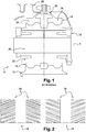
- a speed reducer 10 which is intended to be mounted in an aircraft turbomachine to connect a low-pressure shaft of the turbomachine to a fan of the turbomachine.
- the speed reducer 10 is of the planetary gear type. It comprises a central sun gear 12, a plurality of planet gears 14, of which a single planet gear 14 is shown in figure 1 , a planet carrier 16 on which the planet pinions 14 are rotatably mounted and an annular ring gear 18.
- the planet gear 12 is coaxial with a main axis of the speed reducer 10, it is coupled with each planet gear 14.
- Each satellite pinion 14 is rotatable relative to the planet carrier 16 around an axis A parallel to the main axis of the speed reducer 10.
- the Planet carrier 16 comprises for this purpose several axes 20, each axis 20 of which is associated with a planet gear 14 and which carries out the rotational guidance of the planet gear 14 with respect to the planet carrier 16.
- a bearing 22 is arranged between the planet pinion 14 and the associated shaft 20 to limit friction between these two elements. It will be understood that any type of bearing 22, or any other guide means can be used between the planet pinion 14 and the shaft 20 without departing from the scope of the invention.
- each planet pinion 14 is coupled with both the planetary pinion 12 and the ring gear 18.
- the ring gear 18 comprises for this purpose a toothing on its radially internal face for its coupling with each planet pinion 14.
- the planet pinions 14 comprise for this purpose a complementary toothing.
- the teeth in the speed reducer 10 are also designed not to generate axial stresses in the speed reducer 10, nor on the elements to which the speed reducer 10 is connected.
- the teeth in the reducer are here herringbone teeth or "V" teeth.
- Ring 18 is also made up of two half-rings 24 which are annular, coaxial with the main axis of the speed reducer and which are offset from each other along the main axis of the reducer.
- the two half-rings 24 are connected to each other by a support plate 26.
- the support plate 26 is itself connected to a fixed casing 28 of the turbomachine.
- Each half-ring 24 comprises, on its inner annular face, a helical toothing.
- the inclination of the toothing of one half-ring is opposite to the inclination of the toothing of the other half-ring 24.
- the pattern formed by the two teeth is V-shaped, thus giving its name to this type of teeth.
- each satellite pinion 14 meshes with the crown 18. Consequently, the toothing of each satellite pinion 14 is a herringbone toothing complementary to the toothing of the crown 18.
- each planet gear 14 meshes with the planet gear 12, the toothing of the planet gear 12 is therefore also a herringbone toothing complementary to the toothing of the planet gears 14.
- Each satellite pinion 14 exerts on each half-ring 24 an action breaking down into a tangential force, an axial force oriented parallel to the main axis of the speed reducer 10 and a force oriented radially with respect to the main axis A of the pinion satellite 14.
- the direction of the axial force on a half-ring is defined as a function of the orientation of the toothing of the half-ring 24.
- the axial force on each half-ring 24 is oriented towards the outside of the ring 18 on the left view and it is oriented towards the inside of the crown 14 on the right bue.
- This disengagement is designed to take place when the satellite pinions exert on the half-rings 24 an action whose amplitude is greater than a predefined amplitude value and for which the direction of the axial force is oriented towards the outside of the reducer 10.
- this action causing the disengagement will be called disengagement action.
- the value of the axial force exerted by the planet pinions 14 on the half-rings 24 becomes greater than a predefined force value.
- the amplitude of the declutching action is determined to correspond to a blockage of a component in the turbine engine, which is connected to the speed reducer 10 or else of a component of the speed reducer 10.
- This blockage can be at the level of a bearing 22, in a low pressure stage of the turbomachine or else in the fan of the turbomachine.
- the disengagement of the speed reducer 10 consists in sliding the two half-rings 24 axially and separating them from each other so that they are no longer coupled with the planet pinions 14.
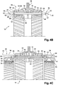
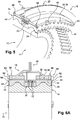
- each half-ring 24 is mounted to slide with respect to the support plate 26 along a direction of sliding parallel to the main axis of the speed reducer 10, between a coupled position, shown in particular in figure 4A and 6A , in which the two half-rings 24 are coupled with the satellite pinions 14 and an uncoupled position, shown in figure 4C and 6C , in which the half-rings 24 are uncoupled from the planet pinions 14.
- the half-rings 24 When the half-rings 24 are in their coupled position, they are preferably bearing axially against each other or against an intermediate component of the support plate 26.
- Each half-ring 24 is thus connected to the support plate 26 with the possibility of axial sliding relative to the support plate 26.
- the speed reducer 10 also comprises means for causing each half-ring 24 to move from the coupled position to the uncoupled position the planet pinions 14 exert the disengaging action on the half-rings 24 and means for retaining each half -crown in the coupled position when the satellite pinions 14 exert an action on each half-crown 24 whose amplitude is less than the predefined amplitude value.
- each half-ring 24 in movement from the coupled position to the uncoupled position is achieved by the action of the satellite pinions 14 on the half-ring 24.
- the satellite pinions 14 exert on each half-crown 24 an action breaking down into a force oriented tangentially with respect to the main axis of the speed reducer 10, an effort oriented axially, that is to say parallel to the main axis of the speed reducer 10 and a force oriented radially with respect to the main axis of each satellite pinion 14.
- the axial force is oriented either towards the inside of the ring 18, or towards the exterior of crown 18 during operation of the turbomachine.
- the speed reducer 10 comprises additional means for driving the half-rings 24 in axial displacement towards the uncoupled position.
- these additional means comprise a helical spring 30 which is compressed axially between each half-ring 24 and a bearing portion of the support plate 26.
- Each spring 30 permanently exerts a force on the associated half-ring 24 which is parallel to the main axis of the speed reducer 10 and oriented towards the outside of the ring 18, that is to say in the direction of the uncoupled position.
- This additional force exerted by the spring makes it possible in particular to accelerate the movement of the half-ring 24 towards the uncoupled position.
- each half-ring 24 with the support plate 26 is made to immobilize the half-rings 24 in rotation relative to the support plate 26 around the main axis of the speed reducer 10, while allowing movement axial of the half-rings 24.
- the support plate 26 comprises grooves 32 distributed over its inner peripheral face 34, which cooperate with complementary grooves 36 distributed over the outer peripheral face 38 of each half-ring 24.
- each half-ring 24 can be connected to the support plate 26 by any other means such as for example by means of at least one set comprising a groove and an associated key.
- the speed reducer 10 comprises means for retaining each half-ring 24 in its coupled position.
- retaining means are made in order to maintain each half-ring 24 in the coupled position when the speed reducer 10 is in normal operating conditions and to no longer retain the half-rings 24 when a blockage in the low-pressure line occurs.
- the retaining means comprise at least one element which is capable of being deformed when the planet pinions exert on each half-ring 24 the disengaging action.
- This deformation of the retaining element may consist of an elastic deformation, a plastic deformation or else a breakage of the element.
- the retaining means comprise a rod 40 oriented parallel to the main axis of the speed reducer 10, which extends axially so as to pass simultaneously through the two half-rings 24.
- Each half-ring 24 has an axial through hole 54 in which rod 40 is received.
- the rod 40 extends axially beyond the half-rings 24, that is to say that each end 42 of the rod 40 projects axially with respect to one of the two half-rings 24, beyond an axial end face 44 of the half-ring 24, which is located axially outside the ring 18, when the half-rings 24 are in their coupled position.
- the rod 40 also includes an intermediate section 46 associated with each half-ring 24 which carries the element to be deformed.
- This element consists of a support member 48 which bears against the axial end face 44 of the associated half-ring 24, and which holds the associated half-ring 24 in its coupled position.
- the support member 48 is designed to deform when the half-ring 24 associated with it undergoes a sufficiently large axial force from the planet pinions 14, which corresponds to the disengagement action.
- the support member 48 consists of a stop ring which is able to deform permanently, that is to say it is able to deform plastically.
- the bearing member 48 consists of an elastic washer which is received in an associated groove formed in the intermediate section 46 of the rod 40.
- the bearing member is thus able to deform elastically to out of the groove when the action causing the movement of the half-rings 24 is exerted.
- the half-ring 24 associated with it can then move towards its uncoupled position under the action in particular of the planet pinions 14, as described previously.
- the rod 40 also comprises abutment means 50 against which each half-ring 24 comes into abutment when it reaches its uncoupled position.
- stop means 50 are carried by each end 42 of the rod 42 and each consist of a washer 52 received in an associated groove formed in the associated end of the rod 50.
- Each abutment means 50 is capable of coming into abutment axially against the half-ring 24.
- each abutment means 50 is capable of coming into abutment against a shoulder 56 formed in the orifice 54 of the associated half-ring 24.
- This embodiment makes it possible to limit the axial length of the rod 40 and thus to limit the total axial size of the speed reducer 10.
- each abutment means 50 against a shoulder, the half-rings 24 remain connected to the support plate 26, even after they have been uncoupled from the satellite pinions 14, which thus makes it possible to avoid that they are ejected and can break another element
- each abutment means 50 is capable of coming into abutment against the axial end face 44 of the associated half-ring 24.
- the retaining means comprise a single rod 40 passing through the two half-rings 24.
- the speed reducer 10 may comprise a plurality of rods 40 similar to that which has just been described, which are distributed in a regular manner around the main axis of the speed reducer 10 and which all cooperate with the two half-rings 24 in the same way, to maintain the half-rings 24 in the coupled position during normal operation of the speed reducer 10 and to allow movement of the half-rings 24 towards their uncoupled position in the case of a force on the half-rings 24, the amplitude of which is significant.
- the orientation of the action exerted by the satellite pinions 14 then has the consequence either of keeping each half-ring 24 bearing axially against the other half-ring 24, or of pressing each half-ring 24 against the support member 48 which is associated with it and which is carried by the rod 40.
- the amplitude of the action being less than the predefined amplitude, the support member 48 does not deform, thus maintaining the half -crown 24 in its coupled position.
- each half-ring 24 is still coupled with the planet gears 14, which in particular allows the planet gears 14 to drive the half-ring 24 towards its uncoupled position during the entirety of this movement.
- each washer 52 of the abutment means 50 is in abutment against the shoulder 56 formed in the orifice 54 of the associated half-ring 24.
- the springs 30 also make it possible to maintain the half-rings 24 in their uncoupled position, thus avoiding any unwanted meshing of the half-rings 24 with the planet gears 14.
- the retaining means comprise at least one fusible abutment 60 associated with each half-ring 24 and against which each half-ring 24 bears axially towards the outside of the ring 18 when the half-ring 24 is in its coupled position.
- the retaining means comprise a plurality of fuse stops 60 evenly distributed around the main axis of the speed reducer 10.
- Each fuse stop 60 is carried by the support plate 26 and bears against the axial end face 44 of the associated half-ring 24. It comprises a portion 62 for fixing the fusible abutment 60 to the support plate 26 and a bearing portion 64 of the fusible abutment 60 against said axial end face 44 of the half-ring 24.
- the two portions 62, 64 of the fusible abutment 60 are interconnected by a portion of low breaking strength which is capable of breaking when the planet pinions 14 exert on the half-rings 24 said disengaging action.
- the support portion 64 When the portion of low breaking strength of the fuse stop 60 has broken, the support portion 64 has separated from the fixing portion 62, the half-ring 24 associated with the fuse stop 60 is not then no longer retained axially in the coupled position, it can then move towards the uncoupled position.
- the retaining means also comprise a ball stop system 66 associated with each half-ring 24 and which is designed to hold the associated half-ring 24 in each of the coupled position or the uncoupled position.
- the ball thrust bearing system 66 comprises a ball 68 which is carried by the support plate 26 and which is mounted to move radially, with respect to the main axis of the speed reducer, with respect to the support plate 26.
- the ball 68 is guided in movement with respect to the support plate 26 by a guide cylinder 70 oriented radially with respect to the main axis of the speed reducer 10 which is mounted in an associated radial hole formed in the support plate 26
- a compression spring is arranged in the guide cylinder to force the ball 68 to an extended position
- Each half-ring 24 has two cavities 72 with one or the other of which the ball 68 is intended to cooperate when the half-ring 24 is in one or the other of the coupled position or the uncoupled position.
- the two cavities 72 are formed in the bottom of a recessed groove of the spline 36 of the half-ring 24 and the ball 68, the guide cylinder 70 and the support spring are carried by a tooth of the associated spline 32 belonging to the support plate 26.
- each half-ring 24 when the speed reducer 10 is in normal operating conditions, each half-ring 24 is in its coupled position.
- the amplitude of the action exerted by the satellite pinions 14 on the half-rings 24 one is less than the predefined amplitude value mentioned above.
- Each ball 68 is further received in a cavity 72 which corresponds to the coupled position.
- the ball thrust bearing 66 cooperates with the fusible thrust bearing 60 to maintain the half-ring 24 in its coupled position.
- each fusible abutment 60 breaks and each ball 68 comes out of the associated cavity, then allowing the axial displacement of the half-rings 24 towards their uncoupled position.
- each half-ring 24 is still coupled with the planet gears 14, which in particular allows the planet gears 14 to drive the half-rings 24 towards their uncoupled position during the entirety of this movement.
- crown 18 forms a rigid subassembly. There is therefore no flexibility induced by the mechanical fuse function in the speed reducer 10.
Description
L'invention concerne un réducteur de vitesse pour turbomachine d'aéronef qui comporte des moyens dits fusibles permettant de désaccoupler les éléments liés par le réducteur.The invention relates to a speed reducer for an aircraft turbomachine which comprises so-called fuse means making it possible to uncouple the elements linked by the reducer.
L'invention concerne plus particulièrement un réducteur de vitesse et de transmission de couple d'entrainement entre un arbre de la turbine basse pression et la soufflante de la turbomachine qui est du type à train épicycloïdal qui comporte lesdits moyens fusibles.The invention relates more particularly to a speed reducer and drive torque transmission between a shaft of the low pressure turbine and the fan of the turbomachine which is of the planetary gear train type which includes said fuse means.
Dans une turbomachine d'aéronef, l'arbre basse pression de la turbomachine, qui relie la turbine basse pression au compresseur basse pression, est aussi relié à une soufflante de la turbomachine.In an aircraft turbomachine, the low-pressure shaft of the turbomachine, which connects the low-pressure turbine to the low-pressure compressor, is also connected to a fan of the turbomachine.
Un réducteur est interposé entre l'arbre basse pression et la soufflante, pour effectuer une réduction de vitesse de rotation. De manière conventionnelle, le réducteur est un réducteur à train épicycloïdal comportant un pignon central solaire accouplé à l'arbre basse pression et un porte satellites qui est accouplé à la soufflante.A reducer is interposed between the low pressure shaft and the fan, to effect a reduction in the speed of rotation. Conventionally, the reduction gear is an epicyclic reduction gear comprising a central sun gear coupled to the low pressure shaft and a planet gear carrier which is coupled to the fan.
La couronne extérieure est fixe et est reliée à un carter de la turbomachine.The outer crown is fixed and is connected to a casing of the turbomachine.
En fonctionnement, certaines pièces de la ligne basse pression qui vient d'être définie précédemment peuvent se bloquer, bloquant ainsi le réducteur. C'est par exemple le cas du grippage des paliers de satellites reliant chaque satellite au porte satellite, l'ingestion d'un corps étranger ou blocage ou freinage dans la ligne basse pression, provoqué par une casse d'une aube par exemple.In operation, some parts of the low pressure line that has just been defined above can jam, thus blocking the reducer. This is for example the case of the seizure of the satellite bearings connecting each satellite to the planet carrier, the ingestion of a foreign body or blockage or braking in the low pressure line, caused by a breakage of a blade for example.
Un tel blocage d'une pièce du système peut provoquer la rupture d'une autre pièce de ce système, et aussi provoquer un blocage de la soufflante, entrainant alors une augmentation de la trainée de la turbomachine et nuisant à la manœuvrabilité de l'aéronef.Such a blockage of a part of the system can cause the breakage of another part of this system, and also cause a blockage of the fan, resulting in then an increase in the drag of the turbomachine and adversely affecting the maneuverability of the aircraft.
Pour empêcher un tel blocage du réducteur, il a été proposé d'incorporer dans la ligne basse pression un ou plusieurs dispositifs de sécurité qui se rompent en cas de blocage.To prevent such blocking of the reducer, it has been proposed to incorporate in the low pressure line one or more safety devices which break in the event of blockage.
De tels dispositifs de sécurité, communément appelés dispositifs fusibles, peuvent être placés en tout endroit dans la ligne basse pression.Such safety devices, commonly called fuse devices, can be placed anywhere in the low pressure line.
Cependant, la conception de ces dispositifs fusibles est difficile à réaliser ainsi qu'à mettre en œuvre puisque l'introduction de tels éléments dans la ligne basse pression correspond à introduire dans la ligne une ou plusieurs zones souples, nuisant ainsi au comportement dynamique de la ligne. Un réducteur selon le préambule de la revendication 1 est connu de
L'invention a pour but de proposer un réducteur de vitesse qui permet d'assurer la fonction de fusible mécanique sans introduire de zone souple dans la ligne basse pression.The object of the invention is to propose a speed reducer which makes it possible to ensure the function of mechanical fuse without introducing a flexible zone into the low pressure line.
L'invention propose un réducteur de vitesse en particulier pour la transmission de couple entre une turbine à gaz et une soufflante dans une turbomachine, comportant une couronne annulaire coaxiale à un axe principal du réducteur de vitesse et présentant une denture radialement interne, au moins un pignon qui est accouplé avec la couronne et qui comporte une denture radialement externe complémentaire de la denture de la couronne annulaire, dans lequel la couronne comporte deux demi-couronnes annulaires décalées l'une par rapport à l'autre le long de l'axe principal du réducteur de vitesse et qui sont accouplées avec ledit au moins un pignon et une platine de support des deux demi-couronnes par rapport à laquelle les deux demi-couronnes sont immobiles en rotation autour de l'axe principal du réducteur de vitesse chaque demi-couronne comportant une denture interne hélicoïdale inclinée dans une direction opposée à la direction d'inclinaison de la denture de l'autre demi-couronne, dans lequel chaque demi-couronne est reliée à la platine de support de manière à pouvoir être désaccouplée dudit au moins un pignon lorsque ledit au moins un pignon exerce sur chaque demi-couronne une action de débrayage dont l'amplitude est supérieure à une valeur d'amplitude déterminée.The invention proposes a speed reducer in particular for the transmission of torque between a gas turbine and a fan in a turbomachine, comprising an annular ring coaxial with a main axis of the speed reducer and having radially internal toothing, at least one pinion which is coupled with the crown and which comprises a radially external toothing complementary to the toothing of the annular crown, in which the crown comprises two annular half-crowns offset with respect to one another along the main axis of the speed reducer and which are coupled with said at least one pinion and a support plate for the two half-rings with respect to which the two half-rings are stationary in rotation around the main axis of the speed reducer each half- crown comprising an internal helical toothing inclined in a direction opposite to the direction of inclination of the toothing of the other half-crown, in which that each half-ring is connected to the support plate so as to be able to be uncoupled from said at least one pinion when said at least one pinion exerts on each half-ring a disengagement action the amplitude of which is greater than a determined amplitude value.
La liaison des demi-couronnes entre elles et avec la platine de support permet d'assurer la fonction de fusible mécanique tout en permettant d'avoir un système rigide lorsque les demi-couronnes sont solidaires l'une de l'autre. Il n'y a donc pas de zone souple induite par cette solution.The connection of the half-rings between them and with the support plate makes it possible to ensure the function of mechanical fuse while allowing to have a rigid system when the half-rings are integral with one another. There is therefore no soft zone induced by this solution.
Selon l'invention, chaque demi-couronne est montée coulissante par rapport à la platine de support selon une direction parallèle à l'axe principal du réducteur de vitesse entre une position accouplée dans laquelle ladite demi-couronne est accouplée avec ledit au moins un pignon et une position désaccouplée dans laquelle ladite demi-couronne est désaccouplée dudit au moins un pignon,
et le réducteur de vitesse comporte des moyens de retenue de ladite demi-couronne dans sa position accouplée, lesdits moyens de retenue étant aptes à être désengagés pour permettre un déplacement de ladite demi-couronne vers la position désaccouplée lorsque ledit au moins un pignon exerce sur chaque demi-couronne ladite action de débrayage.According to the invention, each half-ring is mounted to slide with respect to the support plate in a direction parallel to the main axis of the speed reducer between a coupled position in which said half-ring is coupled with said at least one pinion and an uncoupled position in which said half-ring is uncoupled from said at least one pinion,
and the speed reducer comprises means for retaining said half-ring in its coupled position, said retaining means being able to be disengaged to allow movement of said half-ring to the uncoupled position when said at least one pinion exerts on each half-ring said disengaging action.
De préférence, les moyens de retenue comportent au moins un organe d'appui associé à chaque demi-couronne qui est en appui axialement contre une face d'appui de la demi-couronne qui lui est associée, et qui est apte à changer d'état lorsque ledit au moins un pignon exerce sur la demi-couronne ladite action de débrayage.Preferably, the retaining means comprise at least one bearing member associated with each half-ring which bears axially against a bearing face of the half-ring which is associated with it, and which is capable of changing state when said at least one pinion exerts said disengaging action on the half-ring.
De préférence, l'organe d'appui consiste en un anneau d'arrêt déformable associé à chaque demi-couronne qui est en appui contre ladite face d'appui de la demi-couronne qui lui est associée et qui est porté par une tige orientée parallèlement à l'axe principal du réducteur de vitesse et qui traverse un orifice axial réalisé dans les deux demi-couronnes,Preferably, the bearing member consists of a deformable stop ring associated with each half-ring which bears against said bearing face of the half-ring which is associated with it and which is carried by a rod oriented parallel to the main axis of the speed reducer and which passes through an axial hole made in the two half-rings,
De préférence, l'organe d'appui comporte une butée fusible qui est apte se rompre lorsque ledit au moins un pignon exerce sur la demi-couronne ladite action.Preferably, the support member comprises a fusible abutment which is capable of breaking when said at least one pinion exerts said action on the half-ring.
De préférence, la butée fusible comporte une portion de fixation de la butée fusible à la platine de support et une portion d'appui de la butée fusible contre ladite face d'appui de la demi-couronne.Preferably, the fusible abutment comprises a portion for fixing the fusible abutment to the support plate and a bearing portion of the fusible abutment against said bearing face of the half-ring.
De préférence, les moyens de retenue comportent un organe de butée associé à chaque demi-couronne qui est apte à coopérer avec la demi-couronne associée lorsqu'elle est dans sa position désaccouplée.Preferably, the retaining means comprise an abutment member associated with each half-ring which is capable of cooperating with the associated half-ring when it is in its uncoupled position.
De préférence, l'organe de butée comporte une rondelle reçue dans une gorge associée formée dans une extrémité de la tige associée à ladite demi-couronne.Preferably, the abutment member comprises a washer received in an associated groove formed in one end of the rod associated with said half-ring.
De préférence, l'organe de butée comporte au moins une butée à bille agencée dans une cannelure de la platine de support qui est apte à coopérer avec la demi-couronne associée lorsqu'elle est dans l'une de la position désaccouplée et de la position accouplée.Preferably, the abutment member comprises at least one ball abutment arranged in a groove of the support plate which is capable of cooperating with the associated half-ring when it is in one of the uncoupled position and of the coupled position.
De préférence, chaque demi-couronne est entrainée en déplacement vers sa position désaccouplée par l'intermédiaire de l'effort axial résultant de l'action dudit au moins un pignon sur la denture hélicoïdale de la demi-couronne.Preferably, each half-ring is driven in movement towards its uncoupled position via the axial force resulting from the action of said at least one pinion on the helical toothing of the half-ring.
De préférence, le réducteur de vitesse comporte des moyens supplémentaires d'entrainement de chaque demi-couronne en déplacement vers sa position désaccouplée.Preferably, the speed reducer comprises additional means for driving each half-ring in movement towards its uncoupled position.
De préférence, lesdits moyens supplémentaire d'entrainement comportent un ressort de compression qui est comprimé axialement entre les deux demi-couronnes.Preferably, said additional drive means comprise a compression spring which is compressed axially between the two half-rings.
De préférence, le réducteur de vitesse consiste en un réducteur du type à train épicycloïdal et ladite couronne est la couronne annulaire externe du train épicycloïdal et ledit au moins un pignon consiste en une pluralité de pignons satellites reliés les uns aux autres par un porte satellites.Preferably, the speed reducer consists of a reducer of the planetary gear type and said ring gear is the external annular ring gear of the planetary gear train and said at least one pinion consists of a plurality of planet pinions connected to each other by a planet carrier.
L'invention propose aussi une turbomachine d'aéronef comportant une turbine basse pression, un arbre basse pression qui est accouplée à la turbine basse pression et une soufflante qui est accouplée à l'arbre basse pression, caractérisée en ce qu'elle comporte un réducteur de vitesse selon l'invention, par l'intermédiaire duquel la soufflante est accouplée à l'arbre basse pression.The invention also proposes an aircraft turbomachine comprising a low pressure turbine, a low pressure shaft which is coupled to the low pressure turbine and a fan which is coupled to the low pressure shaft, characterized in that it comprises a reducer speed according to the invention, through which the fan is coupled to the low pressure shaft.
D'autres caractéristiques et avantages de l'invention apparaîtront à la lecture de la description détaillée qui suit pour la compréhension de laquelle on se reportera aux figures annexées parmi lesquelles :
- la
figure 1 est une vue en section axiale partielle d'un réducteur de vitesse de type à train épicycloïdal selon l'art antérieur ; - la
figure 2 est une représentation schématique d'une partie de la face annulaire interne dentée des demi-couronnes représentées à lafigure 1 , montrant deux orientations possibles de leurs dentures hélicoïdales ; - la
figure 3 est une représentation schématique avec arrachement d'un premier mode de réalisation d'un réducteur de vitesse selon l'invention ; - les
figures 4A à 4C sont des sections axiales du réducteur de vitesse représenté à lafigure 3 , montrant différents états du réducteur ; - la
figure 5 est une représentation schématique avec arrachement d'un deuxième mode de réalisation d'un réducteur de vitesse selon l'invention ; - les
figures 6A à 6C sont des sections axiales du réducteur de vitesse représenté à lafigure 5 , montrant différents états du réducteur.
- the
figure 1 is a partial axial sectional view of a prior art planetary gear type speed reducer; - the
picture 2 is a schematic representation of part of the internal toothed annular face of the half-rings shown infigure 1 , showing two possible orientations of their helical teeth; - the
picture 3 is a schematic cut-away representation of a first embodiment of a speed reducer according to the invention; - the
figures 4A to 4C are axial sections of the speed reducer shown inpicture 3 , showing different states of the reducer; - the
figure 5 is a schematic cut-away representation of a second embodiment of a speed reducer according to the invention; - the
figures 6A to 6C are axial sections of the speed reducer shown infigure 5 , showing different states of the reducer.
On a représenté à la
Le réducteur de vitesse 10 est du type à train épicycloïdal. Il comporte un pignon planétaire central 12, une pluralité de pignons satellites 14, dont un seul pignon satellite 14 est représenté à la
Le pignon planétaire 12 est coaxial à un axe principal du réducteur de vitesse 10, il est accouplé avec chaque pignon satellite 14.The
Chaque pignon satellite 14 est mobile en rotation par rapport au porte satellites 16 autour d'un axe A parallèle à l'axe principal du réducteur de vitesse 10. Le porte satellites 16 comporte à cet effet plusieurs axes 20, dont chaque axe 20 est associé à un pignon satellite 14 et qui réalise le guidage en rotation du pignon satellite 14 par rapport au porte satellites 16.Each
Un palier 22 est disposé entre le pignon satellite 14 et l'axe 20 associé pour limiter les frottements entre ces deux éléments. Il sera compris que tout type de palier 22, ou tout autre moyen de guidage peut être utilisé entre le pignon satellite 14 et l'axe 20 sans sortir du domaine de l'invention.A
Aussi, chaque pignon satellite 14 est accouplé à la fois avec le pignon planétaire 12 et la couronne 18.Also, each
La couronne 18 comporte à cet effet une denture sur sa face radialement interne pour son accouplement avec chaque pignon satellite 14. Les pignons satellites 14 comportent à cet effet une denture complémentaire.The
Les dentures dans le réducteur de vitesse 10 sont en outre conçues pour ne pas générer de contraintes axiales dans le réducteur de vitesse 10, ni sur les éléments auxquels le réducteur de vitesse 10 est connecté.The teeth in the
Comme on peut le voir à la
La couronne 18 est en outre constituée de deux demi-couronnes 24 qui sont annulaires, coaxiales à l'axe principal du réducteur de vitesse et qui sont décalées l'une par rapport à l'autre selon l'axe principal du réducteur.
Les deux demi-couronnes 24 sont reliées l'une avec l'autre par une platine de support 26. La platine de support 26 est elle-même reliée à un carter 28 fixe de la turbomachine.The two half-
Chaque demi-couronne 24 comporte, sur sa face annulaire interne, une denture hélicoïdale. L'inclinaison de la denture d'une demi-couronne est opposée à l'inclinaison de la denture de l'autre demi-couronne 24. Ainsi, comme on peut le voir à la
Chaque pignon satellite 14 engrène avec la couronne 18. Par conséquent, la denture de chaque pignon satellite 14 est une denture en chevron complémentaire de la denture de la couronne 18.Each
Aussi, chaque pignon satellite 14 engrène avec le pignon planétaire 12, la denture du pignon planétaire 12 est donc elle aussi une denture en chevron complémentaire de la denture des pignons satellites 14.Also, each
Chaque pignon satellite 14 exerce sur chaque demi-couronne 24 une action se décomposant en un effort tangentiel, un effort axial orienté parallèlement à l'axe principal du réducteur de vitesse 10 et un effort orienté radialement par rapport à l'axe principal A du pignon satellite 14.Each
La direction de l'effort axial sur une demi-couronne est définie en fonction de l'orientation de la denture de la demi-couronne 24. Ainsi, comme on peut le voir à la
On a représenté aux
Ce débrayage est prévu pour avoir lieu lorsque les pignons satellites exercent sur les demi-couronnes 24 une action dont l'amplitude est supérieure à une valeur d'amplitude prédéfinie et pour laquelle la direction de l'effort axial est orientée vers l'extérieur du réducteur 10. Dans la description qui va suivre cette action provoquant le débrayage sera appelée action de débrayage.This disengagement is designed to take place when the satellite pinions exert on the half-
Ainsi, lorsque les pignons satellites exercent sur les demi-couronnes 24 l'action de débrayage, la valeur de l'effort axial exercé par les pignons satellites 14 sur les demi-couronnes 24 devient supérieure à une valeur d'effort prédéfinie.Thus, when the planet pinions exert on the half-
De préférence, l'amplitude de l'action de débrayage est déterminée pour correspondre à un blocage d'un composant dans la turbomachine, qui est relié au réducteur de vitesse 10 ou bien d'un composant du réducteur de vitesse 10.Preferably, the amplitude of the declutching action is determined to correspond to a blockage of a component in the turbine engine, which is connected to the
Ce blocage peut être au niveau d'un palier 22, dans un étage basse pression de la turbomachine ou bien dans la soufflante de la turbomachine.This blockage can be at the level of a
Ainsi, en prévoyant un débrayage du réducteur de vitesse 10, le blocage d'un de ces composant ne nuira pas à l'intégrité des autres composants ni à la manœuvrabilité de l'aéronef sur lequel le réducteur de vitesse 10 est monté.Thus, by providing for a disengagement of the
Le débrayage du réducteur de vitesse 10 consiste à faire coulisser axialement les deux demi-couronnes 24 et en les écartant l'une de l'autre afin qu'elles ne soient plus accouplées avec les pignons satellites 14.The disengagement of the
Ainsi, chaque demi-couronne 24 est monté coulissante par rapport à la platine de support 26 selon une direction de coulissement parallèle à l'axe principal du réducteur de vitesse 10, entre une position accouplée, représentée notamment aux
Lorsque les demi-couronnes 24 sont dans leur position accouplée, elles sont de préférence en appui axialement l'une contre l'autre ou contre un composant intermédiaire de la platine de support 26.When the half-
Chaque demi-couronne 24 est ainsi reliée à la platine de support 26 avec possibilité de coulissement axial par rapport à la platine de support 26.Each half-
Le réducteur de vitesse 10 comporte aussi des moyens pour entrainer chaque demi-couronne 24 en déplacement depuis la position accouplée vers la position désaccouplée les pignons satellites 14 exercent l'action de débrayage sur les demi-couronnes 24 et des moyens de retenue de chaque demi-couronne dans la position accouplée lorsque les pignons satellites 14 exercent une action sur chaque demi-couronne 24 dont l'amplitude est inférieure à la valeur d'amplitude prédéfinie.The
L'entrainement de chaque demi-couronne 24 en déplacement depuis la position accouplée vers la position désaccouplée est réalisé par l'action des pignons satellites 14 sur la demi-couronne 24. En effet, comme on l'a dit précédemment, du fait de la coopération des dentures hélicoïdales complémentaires de chaque demi-couronne 24 et des pignons satellites 14, les pignons satellites 14 exercent sur chaque demi-couronne 24 une action se décomposant en un effort orienté tangentiellement par rapport à l'axe principal du réducteur de vitesse 10 ,un effort orienté axialement c'est à dire parallèle à l'axe principal du réducteur de vitesse 10 et un effort orienté radialement par rapport à l'axe principal de chaque pignon satellite 14.The driving of each half-
En fonction de l'orientation des dentures et en fonction de la direction de l'action exercée par les pignons satellites 14 sur chaque demi-couronne 24, l'effort axial est orienté soit vers l'intérieur de la couronne 18, soit vers l'extérieur de la couronne 18 lors du fonctionnement de la turbomachine.Depending on the orientation of the teeth and depending on the direction of the action exerted by the satellite pinions 14 on each half-
Par conséquent, lorsque l'action exercée par les pignons satellites 14 sur chaque demi-couronne 24 a pour conséquence que cet effort axial est orienté vers l'extérieur de la couronne 18, (et supérieur à la valeur prédéfinie pour la casse du fusible) cet effort axial permet l'entrainement de chaque demi-couronne 24 vers sa position désaccouplée.Consequently, when the action exerted by the satellite pinions 14 on each half-
Selon une variante de réalisation, et comme on peut le voir plus en détails aux figures, le réducteur de vitesse 10 comporte des moyens supplémentaires d'entrainement des demi-couronnes 24 en déplacement axial vers la position désaccouplée.According to a variant embodiment, and as can be seen in more detail in the figures, the
Ici, ces moyens supplémentaires comportent un ressort hélicoïdal 30 qui est comprimé axialement entre chaque demi-couronne 24 et une portion d'appui de la platine de support 26.Here, these additional means comprise a
Chaque ressort 30 exerce en permanence un effort sur la demi-couronne 24 associée qui est parallèle à l'axe principal du réducteur de vitesse 10 et orienté vers l'extérieur de la couronne 18, c'est-à-dire en direction de la position désaccouplée.Each
Cet effort supplémentaire exercé par le ressort permet notamment d'accélérer le déplacement de la demi-couronne 24 vers la position désaccouplée.This additional force exerted by the spring makes it possible in particular to accelerate the movement of the half-
La liaison de chaque demi-couronne 24 avec la platine de support 26 est réalisée pour immobiliser les demi-couronnes 24 en rotation par rapport à la platine de support 26 autour de l'axe principal du réducteur de vitesse 10, tout en permettant le déplacement axial des demi-couronnes 24.The connection of each half-
A cet effet, la platine de support 26 comporte des cannelures 32 réparties sur sa face périphérique interne 34, qui coopèrent avec des cannelures 36 complémentaires réparties sur la face périphérique externe 38 de chaque demi-couronne 24.For this purpose, the
Il sera compris que l'invention n'est pas limitée à ce mode de réalisation et que chaque demi-couronne 24 peut être reliée à la platine de support 26 par tout autre moyen comme par exemple par l'intermédiaire d'au moins un ensemble comportant une rainure et une clavette associée.It will be understood that the invention is not limited to this embodiment and that each half-
Le réducteur de vitesse 10 comporte des moyens de retenue de chaque demi-couronne 24 dans sa position accouplée.The
Ces moyens de retenue sont réalisés afin de maintenir chaque demi-couronne 24 en position accouplée lorsque le réducteur de vitesse 10 est en conditions de fonctionnement normales et pour ne plus retenir les demi-couronnes 24 lorsqu'un blocage dans la ligne basse pression intervient.These retaining means are made in order to maintain each half-
Selon les modes de réalisation représentés aux figures, les moyens de retenue comportent au moins un élément qui est apte à être déformé lorsque les pignons satellite exercent sur chaque demi-couronne 24 l'action de débrayage. Cette déformation de l'élément de retenue peut consister en une déformation élastique, une déformation plastique ou bien une casse de l'élément.According to the embodiments shown in the figures, the retaining means comprise at least one element which is capable of being deformed when the planet pinions exert on each half-
Selon le mode de réalisation représenté aux
La tige 40 s'étend axialement au-delà des demi-couronnes 24, c'est-à-dire que chaque extrémité 42 de la tige 40 fait saillie axialement par rapport à une des deux demi-couronnes 24, au-delà d'une face d'extrémité axiale 44 de la demi-couronne 24, qui est située à l'extérieur axialement de la couronne 18, lorsque les demi-couronnes 24 sont dans leur position accouplée.The
La tige 40 comporte aussi un tronçon intermédiaire 46 associé à chaque demi-couronne 24 qui porte l'élément à être déformé.The
Cet élément consiste en un organe d'appui 48 qui est en appui contre la face d'extrémité axiale 44 de la demi-couronne 24 associée, et qui maintient la demi-couronne 24 associée dans sa position accouplée.This element consists of a
L'organe d'appui 48 est conçu pour se déformer lorsque la demi-couronne 24 qui lui est associée subit de la part des pignons satellites 14 un effort axial suffisamment important, qui correspond à l'action de débrayage.The
Ici, l'organe d'appui 48 consiste en un anneau d'arrêt qui est apte à se déformer de manière permanente, c'est-à-dire qu'il est apte à se déformer plastiquement.Here, the
Selon une variante de réalisation, l'organe d'appui 48 consiste en une rondelle élastique qui est reçue dans une gorge associée formée dans le tronçon intermédiaire 46 de la tige 40. L'organe d'appui est ainsi apte à se déformer élastiquement pour sortir de la gorge lorsque l'action provoquant le déplacement des demi-couronnes 24 est exercée.According to a variant embodiment, the bearing
Une fois que l'organe d'appui 48 s'est déformé, la demi-couronne 24 qui lui est associée peut alors se déplacer vers sa position désaccouplée sous l'action notamment des pignons satellites 14, comme on l'a décrit précédemment.Once the bearing
La tige 40 comporte aussi des moyens de butée 50 contre lesquels chaque demi-couronne 24 vient en butée lorsqu'elle atteint sa position désaccouplée.The
Ces moyens de butée 50 sont portés par chaque extrémité 42 de la tige 42 et consistent chacun en une rondelle 52 reçue dans une gorge associée formée dans l'extrémité associée de la tige 50.These stop means 50 are carried by each
Chaque moyen de butée 50 est apte à venir en butée axialement contre la demi-couronne 24.Each abutment means 50 is capable of coming into abutment axially against the half-
Ici, chaque moyen de butée 50 est apte à venir en butée contre un épaulement 56 formé dans l'orifice 54 de la demi-couronne 24 associée. Ce mode de réalisation permet de limiter la longueur axiale de la tige 40 et ainsi de limiter l'encombrement axial total du réducteur de vitesse 10.Here, each abutment means 50 is capable of coming into abutment against a
Aussi, grâce à cet appui de chaque moyen de butée 50 contre un épaulement, les demi-couronnes 24 restent reliées au à la platine de support 26, même après leur désaccouplement d'avec les pignons satellites 14, ce qui permet ainsi d'éviter qu'elles soient éjectées et puissent casser un autre élémentAlso, thanks to this support of each abutment means 50 against a shoulder, the half-
Selon une variante de réalisation (non représentée), chaque moyen de butée 50 est apte à venir en butée contre la face d'extrémité axiale 44 de la demi-couronne 24 associée.According to a variant embodiment (not shown), each abutment means 50 is capable of coming into abutment against the axial end face 44 of the associated half-
Dans le mode de réalisation qui vient d'être décrit, les moyens de retenue comportent une seule tige 40 traversant les deux demi-couronnes 24.In the embodiment which has just been described, the retaining means comprise a
Il sera compris que l'invention n'est pas limitée à ce mode de réalisation et que le réducteur de vitesse 10 peut comporter une pluralité de tiges 40 similaires à celle qui vient d'être décrite, qui sont réparties de manière régulière autour de l'axe principal du réducteur de vitesse 10 et qui coopèrent toutes avec les deux demi-couronnes 24 de la même façon, pour maintenir les demi-couronnes 24 dans la position accouplée lors du fonctionnement normal du réducteur de vitesse 10 et pour permettre le déplacement des demi-couronnes 24 vers leur position désaccouplée dans le cas d'un effort sur les demi couronnes 24 dont l'amplitude est importante.It will be understood that the invention is not limited to this embodiment and that the
Ainsi, comme on peut le voir à la
L'orientation de l'action exercée par les pignons satellites 14 a alors pour conséquence soit de maintenir chaque demi-couronne 24 en appui axialement contre l'autre demi-couronne 24, soit de mettre en appui chaque demi-couronne 24 contre l'organe d'appui 48 qui lui est associé et qui est porté par la tige 40. L'amplitude de l'action étant inférieure à la d'amplitude prédéfinie, l'organe d'appui 48 ne se déforme pas, maintenant ainsi la demi-couronne 24 dans sa position accouplée.The orientation of the action exerted by the satellite pinions 14 then has the consequence either of keeping each half-
Comme on peut le voir à la
Pendant son déplacement, chaque demi-couronne 24 est encore accouplée avec les pignons satellites 14, ce qui permet notamment aux pignons satellites 14 d'entrainer la demi-couronne 24 vers sa position désaccouplée pendant la totalité de ce déplacement.During its movement, each half-
Enfin, lorsque chaque demi-couronne 24 atteint sa position désaccouplée représentée à la
Dans cette position, chaque rondelle 52 des moyens de butée 50 est en butée contre l'épaulement 56 formé dans l'orifice 54 de la demi-couronne 24 associée.In this position, each
Les ressorts 30 permettent en outre de maintenir les demi-couronnes 24 dans leur position désaccouplée, évitant ainsi tout engrènement non voulu des demi-couronnes 24 avec les pignons satellites 14.The
On a représenté aux
De préférence, les moyens de retenue comportent une pluralité de butées fusibles 60 réparties de manière régulière autour de l'axe principal du réducteur de vitesse 10.Preferably, the retaining means comprise a plurality of fuse stops 60 evenly distributed around the main axis of the
Chaque butée fusible 60 est portée par la platine de support 26 et est en appui contre la face d'extrémité axiale 44 de la demi-couronne 24 associée. Elle comporte une portion de fixation 62 de la butée fusible 60 à la platine de support 26 et une portion d'appui 64 de la butée fusible 60 contre ladite face d'extrémité axiale 44 de la demi-couronne 24.Each
Les deux portions 62, 64 de la butée fusible 60 sont reliées entre elles par une portion de faible résistance à la rupture qui est apte à rompre lorsque les pignons satellites 14 exercent sur les demi-couronnes 24 ladite action de débrayage.The two
Lorsque la portion de faible résistance à la rupture de la butée fusible 60 s'est rompue, la portion d'appui 64 s'est désolidarisée de la portion de fixation 62, la demi-couronne 24 associée à la butée fusible 60 n'est alors plus retenue axialement dans la position accouplée, elle peut alors se déplacer vers la position désaccouplée.When the portion of low breaking strength of the
Les moyens de retenue comportent aussi un système de butée à bille 66 associé à chaque demi-couronne 24 et qui est réalisé pour maintenir la demi-couronne 24 associée dans chacune de la position accouplée ou de la position désaccouplée.The retaining means also comprise a
Ici, le système de butée à bille 66 comporte une bille 68 qui est portée par la platine de support 26 et qui est montée mobile radialement, par rapport à l'axe principal du réducteur de vitesse, par rapport à la platine de support 26.Here, the ball thrust
La bille 68 est guidée en déplacement par rapport à la platine de support 26 par un cylindre de guidage 70 orienté radialement par rapport à l'axe principal du réducteur de vitesse 10 qui est monté dans un orifice radial associé formé dans la platine de support 26. Un ressort de compression est agencé dans le cylindre de guidage pour forcer la bille 68 vers une position déployéeThe
Chaque demi-couronne 24 comporte deux cavités 72 avec l'une ou l'autre desquelles la bille 68 est destinée à coopérer lorsque la demi-couronne 24 est dans l'une ou l'autre de la position accouplée ou de la position désaccouplée.Each half-
Ici, selon un mode de réalisation préféré, les deux cavités 72 sont formées dans le fond d'une gorge en creux de la cannelure 36 de la demi-couronne 24 et la bille 68, le cylindre de guidage 70 et le ressort d'appui sont portés par une dent de la cannelure 32 associée appartenant à la platine de support 26.Here, according to a preferred embodiment, the two
Ainsi, comme on peut le voir à la
Chaque bille 68 est en outre reçue dans une cavité 72 qui correspond à la position accouplée.Each
L'orientation de l'action exercée par les pignons satellites 14 a alors pour conséquence soit de maintenir chaque demi-couronne 24 en appui axialement contre l'autre demi-couronne 24, soit de mettre en appui chaque demi-couronne 24 contre la butée fusible 60 qui lui est associée L'amplitude de l'action étant inférieure à la d'amplitude prédéfinie, la butée fusible 60 ne se rompt pas, maintenant ainsi la demi-couronne 24 dans sa position accouplée.The orientation of the action exerted by the satellite pinions 14 then has the consequence either of keeping each half-
De plus, la butée à bille 66 coopère avec la butée fusible 60 pour maintenir la demi-couronne 24 dans sa position accouplée.In addition, the ball thrust bearing 66 cooperates with the fusible thrust bearing 60 to maintain the half-
Comme on peut le voir à la
Pendant ce déplacement, chaque demi-couronne 24 est encore accouplée avec les pignons satellites 14, ce qui permet notamment aux pignons satellites 14 d'entrainer les demi-couronnes 24 vers leur position désaccouplée pendant la totalité de ce déplacement.During this movement, each half-
Enfin, lorsque chaque demi-couronne 24 atteint sa position désaccouplée représentée à la
Dans cette position, les billes 68 sont reçues dans les deuxièmes cavités 72 associées, ce qui permet, en association avec les ressorts 30, de maintenir les demi-couronnes 24 dans leur position désaccouplée, évitant ainsi tout engrènement non voulu des demi-couronnes 24 avec les pignons satellites 14.In this position, the
Quel que soit le mode de réalisation du réducteur de vitesse 10, lorsque les demi-couronnes 24 sont dans leur position accouplée, elles sont fixées à la platine de support 26 par l'intermédiaire des cannelures 32, 36 et des moyens de retenue.Whatever the embodiment of the
Par conséquent, les différents composants de la couronne 18 forment un sous-ensemble rigide. Il n'y a donc pas de souplesse induite par la fonction de fusible mécanique dans le réducteur de vitesse 10.Consequently, the various components of
De plus, la majeure partie des composants permettant d'assurer cette fonction de fusible mécanique dans le réducteur de vitesse 10 sont incorporés aux composants de la couronne, que ce soit dans les demi-couronnes 24 ou dans la platine de support 26.In addition, most of the components making it possible to ensure this function of mechanical fuse in the
Il en résulte qu'en fonctionnement normal, l'encombrement total du réducteur de vitesse 10 n'est que peu augmenté par rapport à l'encombrement d'un réducteur de vitesse conventionnel comportant pas la fonction de fusible mécanique.It follows that in normal operation, the total size of the
Claims (13)
- A speed reducer (10), in particular for torque transmission between a gas turbine and a fan in a turbomachine, includingan annular ring gear (18) coaxial to a main axis of the speed reducer (10) and having radially inner teeth,at least one gear (14) which is coupled with the ring gear (18) and which includes radially outer teeth complementary to the teeth of the annular ring gear (18),wherein the ring gear (18) includes two annular half-ring gears (24) offset with respect to each other along the main axis of the speed reducer (10) and which are coupled with said at least one gear (14), and a support plate (26) for supporting both half-ring gears (24), with respect to which both half-ring gears (24) are rotatably immovable about the main axis of the speed reducer (10), each half-ring gear (24) including helical inner teeth tilted in a direction opposite to the tilt direction of the teeth of the other half-ring gear (24),wherein each half-ring gear (24) is connected to the support plate (26) so as to be able to be uncoupled from said at least one gear (14) when said at least one gear (14) exerts on each half-ring gear (24) an unclutching action the amplitude of which is higher than a determined amplitude value,characterised in that each half-ring gear (24) is slidably mounted with respect to the support plate (26), along a direction parallel to the main axis of the speed reducer (10), between a coupled position in which said half-ring gear (24) is coupled with said at least one gear (14) and an uncoupled position in which said half-ring gear (24) is uncoupled from said at least one gear (14),and in that the speed reducer (10) includes retaining means (48, 60) for retaining said half-ring gear (24) in its coupled position, said retaining means (48, 60) being able to be disengaged to enable said half-ring gear (24) to be moved to the uncoupled position when said at least one gear (14) exerts on each half-ring gear (24) said unclutching action.
- The speed reducer (10) according to claim 1, characterised in that the retaining means include at least one abutting member (48, 60) associated with each half-ring gear (24), which axially abuts against an abutting face (44) of the half-ring gear (24) associated therewith, and which is able to change state when said at least one gear (14) exerts on the half-ring gear (24) said unclutching action.
- The speed reducer (10) according to the preceding claim, characterised in that the abutting member consists of a deformable stop ring (48) associated with each half-ring gear (24), which abuts against said abutting face (44) of the half-ring gear (24) associated therewith and which is carried by a rod (40) oriented parallel to the main axis of the speed reducer (10) and which passes through an axial port (54) made in both half-ring gears (24).
- The speed reducer (10) according to claim 2, characterised in that the abutting member includes a fusible thrust bearing (60) which is able to be ruptured when said at least one gear (14) exerts on the half-ring gear (24) said action.
- The speed reducer (10) according to claim 4, characterised in that the fusible thrust bearing (60) includes an attachment portion (62) for attaching the fusible thrust bearing (60) to the support plate (26) and an abutting portion (64) for abutting the fusible thrust bearing (60) against said abutting face (44) of the half-ring gear (24).
- The speed reducer (10) according to any of claims 1 to 5, characterised in that the retaining means include a thrust bearing member (50, 66) associated with each half-ring gear (24), which is able to cooperate with the associated half-ring gear (24) when it is in its uncoupled position.
- The speed reducer (10) according to claim 6, in combination with claim 4, characterised in that the thrust bearing member includes a washer (50) received in an associated groove (52) formed in one end (42) of the rod (40) associated with said half-ring gear (24).
- The speed reducer (10) according to claim 6, in combination with claim 5 or 6, characterised in that the thrust bearing member includes at least one ball thrust bearing (66) arranged in a spline (32) of the support plate (26), which is able to cooperate with the associated half-ringgear (24) when it is in one of the uncoupled position and the coupled position.
- The speed reducer (10) according to any of claims 1 to 8, characterised in that each half-ring gear (24) is movably driven to its uncoupled position through the axial force resulting from the action of said at least one gear (14) on the helical teeth of the half-ring gear (24).
- The speed reducer (10) according to the preceding claim, characterised in that it includes further means (30) for movably driving each half-ring gear (24) to its uncoupled position.
- The speed reducer (10) according to the preceding claim, characterised in that said further driving means include a compression spring (30) which is axially compressed between both half-ring gears (24).
- The speed reducer (10) according to any of the preceding claims, characterised in that it consists of a planetary gearset type reducer and in that said ring gear (18) is the outer annular ring gear of the gearset and said at least one gear (14) consists of a plurality of planet gears (14) connected to each other by a planet carrier (16).
- An aircraft turbomachine including a low pressure turbine, a low pressure shaft which is coupled with the low pressure turbine and a fan which is coupled with the low pressure shaft, characterised in that it includes a speed reducer (10) according to any of the preceding claims, through which the fan is coupled with the low pressure shaft.
Applications Claiming Priority (2)
| Application Number | Priority Date | Filing Date | Title |
|---|---|---|---|
| FR1753956A FR3066004B1 (en) | 2017-05-04 | 2017-05-04 | DECLUTABLE SPEED REDUCER |
| PCT/FR2018/051084 WO2018202990A1 (en) | 2017-05-04 | 2018-05-02 | Disengageable speed-reducing unit |
Publications (2)
| Publication Number | Publication Date |
|---|---|
| EP3596360A1 EP3596360A1 (en) | 2020-01-22 |
| EP3596360B1 true EP3596360B1 (en) | 2022-01-12 |
Family
ID=59649832
Family Applications (1)
| Application Number | Title | Priority Date | Filing Date |
|---|---|---|---|
| EP18727854.4A Active EP3596360B1 (en) | 2017-05-04 | 2018-05-02 | Disengageable speed-reducing unit |
Country Status (5)
| Country | Link |
|---|---|
| US (1) | US11028781B2 (en) |
| EP (1) | EP3596360B1 (en) |
| CN (1) | CN110621913B (en) |
| FR (1) | FR3066004B1 (en) |
| WO (1) | WO2018202990A1 (en) |
Families Citing this family (4)
| Publication number | Priority date | Publication date | Assignee | Title |
|---|---|---|---|---|
| JP7343595B2 (en) * | 2019-02-25 | 2023-09-12 | ムーグ インコーポレイテッド | Drive force transmission mechanism and method for stopping transmission of rotational motion from input element to output element |
| US11313438B2 (en) * | 2019-07-18 | 2022-04-26 | Rolls-Royce Plc | Turbofan gas turbine engine with gearbox |
| US11274729B2 (en) * | 2019-07-18 | 2022-03-15 | Rolls-Royce Plc | Turbofan gas turbine engine with gearbox |
| CN113146283B (en) * | 2021-03-02 | 2022-03-15 | 中国船舶重工集团公司第七一六研究所 | Automatic clamping and rotating device for cylindrical workpiece |
Family Cites Families (19)
| Publication number | Priority date | Publication date | Assignee | Title |
|---|---|---|---|---|
| US1925943A (en) * | 1931-06-20 | 1933-09-05 | Eclipse Aviat Corp | Engine starting mechanism |
| GB784573A (en) * | 1954-11-11 | 1957-10-09 | David Brown And Sons Huddersfi | An improvement in or relating to epicyclic gearing |
| US2926550A (en) * | 1956-03-14 | 1960-03-01 | Wilhelm G Stoeckicht | Marine propulsion plant |
| GB1163024A (en) * | 1966-11-16 | 1969-09-04 | Associatd Electrical Ind Ltd | Improvements relating to Helical Epicyclic Gearing |
| FR2524099A1 (en) * | 1982-03-25 | 1983-09-30 | Cit Alcatel | DEVICE FOR MOUNTING CROWNS OF PLANETARY GEAR TRAINS |
| US5071397A (en) * | 1990-10-01 | 1991-12-10 | Sundstrand Corporation | Jam tolerant geared rotary actuator with automatic disconnect |
| JP4585154B2 (en) * | 2001-08-29 | 2010-11-24 | 住友重機械工業株式会社 | Planetary gear structure |
| JP3745273B2 (en) * | 2001-11-30 | 2006-02-15 | 本田技研工業株式会社 | Internal combustion engine control system for vehicle |
| JP4218561B2 (en) * | 2004-03-22 | 2009-02-04 | 株式会社デンソー | Ring holding device and manufacturing method thereof |
| JP4899082B2 (en) * | 2004-06-08 | 2012-03-21 | Smc株式会社 | Automatic reduction ratio switching device |
| WO2005124188A1 (en) * | 2004-06-22 | 2005-12-29 | Nobuyoshi Sugitani | Gear mechanism, planetary gear device, rotating bearing device, and magical planetary gear speed reducer |
| FR2987416B1 (en) * | 2012-02-23 | 2015-09-04 | Snecma | DEVICE FOR LUBRICATING AN EPICYCLOIDAL REDUCER. |
| RU2627990C2 (en) * | 2012-02-23 | 2017-08-14 | Снекма | Cycloidal reducer, fan module of dual-flow turbojet engine and dual-flow turbojet engine |
| CN103192241B (en) * | 2013-04-03 | 2015-06-10 | 重庆齿轮箱有限责任公司 | Method for machining combined herringbone tooth part |
| US9657813B2 (en) * | 2014-06-06 | 2017-05-23 | Delbert Tesar | Modified parallel eccentric rotary actuator |
| GB201417505D0 (en) * | 2014-10-03 | 2014-11-19 | Rolls Royce Deutschland | A gas turbine architecture |
| FR3028836B1 (en) * | 2014-11-20 | 2016-12-16 | Sagem Defense Securite | ACTUATOR FLIGHT CONTROL ACTUATOR OF AN AIRCRAFT |
| CN105736637B (en) * | 2014-12-08 | 2018-09-28 | 陈伟 | Zero return difference inner swing line speed reducer of industrial robot |
| FR3047279B1 (en) * | 2016-01-28 | 2019-06-07 | Safran Transmission Systems | AXIS-DISTRIBUTED DISTRIBUTION WHEEL AND EPICYCLOIDAL TRAIN REDUCER THUS EQUIPPED |
-
2017
- 2017-05-04 FR FR1753956A patent/FR3066004B1/en active Active
-
2018
- 2018-05-02 CN CN201880029051.3A patent/CN110621913B/en active Active
- 2018-05-02 WO PCT/FR2018/051084 patent/WO2018202990A1/en unknown
- 2018-05-02 US US16/607,225 patent/US11028781B2/en active Active
- 2018-05-02 EP EP18727854.4A patent/EP3596360B1/en active Active
Non-Patent Citations (1)
| Title |
|---|
| None * |
Also Published As
| Publication number | Publication date |
|---|---|
| US11028781B2 (en) | 2021-06-08 |
| FR3066004A1 (en) | 2018-11-09 |
| FR3066004B1 (en) | 2020-09-11 |
| CN110621913A (en) | 2019-12-27 |
| CN110621913B (en) | 2023-04-04 |
| EP3596360A1 (en) | 2020-01-22 |
| US20200378309A1 (en) | 2020-12-03 |
| WO2018202990A1 (en) | 2018-11-08 |
Similar Documents
| Publication | Publication Date | Title |
|---|---|---|
| EP3596360B1 (en) | Disengageable speed-reducing unit | |
| CA2830575C (en) | Shut-off device with automatically activatable locking | |
| EP0415820B1 (en) | Reducing mechanism for articulation with backlash elimination, particularly for use in adjusting the various parts of a vehicle seat | |
| EP3102795B1 (en) | Turbine engine provided with a lubrication unit | |
| CA2640040C (en) | Gear assembly system | |
| FR3038950A1 (en) | ||
| FR2952689A1 (en) | LIMIT SLIDE DIFFERENTIAL WITH DYNAMIC PUSH DEVICE | |
| EP3682141A1 (en) | Pivot for a plain bearing and gearset with reduced thermal stress | |
| FR3036763A1 (en) | EPICYCLOIDAL TRAIN REDUCER | |
| FR1465016A (en) | Differential transmission mechanism | |
| EP3580468B1 (en) | Detachable double-clutch mechanism | |
| EP4247657A1 (en) | Electric drive device for a vehicle axle | |
| EP2498938B1 (en) | Tapping unit with protection means | |
| FR2947218A1 (en) | TRANSMISSION ASSEMBLY OF A MOTOR VEHICLE, IN PARTICULAR RAILWAY | |
| FR2827202A1 (en) | Formation of retaining collar especially for wheel hub bearing uses two tools to deform and deploy hub end | |
| WO2007036633A1 (en) | Safety module for transmission and corresponding assembly | |
| FR2995375A1 (en) | Engagement-disengagement stopper for actuating gear box rotating diaphragm by transmitting axial load from movable piston of car, has ear supporting radial portion of insertion portion and including cavity where radial portion is housed | |
| EP0366563B1 (en) | Self-locking differential | |
| EP3204650A1 (en) | Turbine engine rotating at high speeds | |
| EP2019937B1 (en) | Reduction gearbox device of the nested planetary gear set type | |
| EP3234359B1 (en) | Hydraulic device with radial pistons comprising at least one ball bearing | |
| CA2998653A1 (en) | Toothed gear, gear device, power transmission box and aircraft with a rotary wing | |
| FR2638500A1 (en) | Self-locking differential with epicycloid gear train | |
| FR2959291A1 (en) | Self-locking differential for movement transmission to wheels of vehicle, has satellite assembled on fixed axle with respect to satellite carrying crown, where crown is connected to lid of case by right ramp gear | |
| FR3018328A3 (en) | DIFFERENTIAL FOR MOTOR VEHICLE WITH HOLDING DEVICE IN THE POSITION OF THE AXLE SATELLITE |
Legal Events
| Date | Code | Title | Description |
|---|---|---|---|
| STAA | Information on the status of an ep patent application or granted ep patent |
Free format text: STATUS: UNKNOWN |
|
| STAA | Information on the status of an ep patent application or granted ep patent |
Free format text: STATUS: THE INTERNATIONAL PUBLICATION HAS BEEN MADE |
|
| PUAI | Public reference made under article 153(3) epc to a published international application that has entered the european phase |
Free format text: ORIGINAL CODE: 0009012 |
|
| STAA | Information on the status of an ep patent application or granted ep patent |
Free format text: STATUS: REQUEST FOR EXAMINATION WAS MADE |
|
| 17P | Request for examination filed |
Effective date: 20191017 |
|
| AK | Designated contracting states |
Kind code of ref document: A1 Designated state(s): AL AT BE BG CH CY CZ DE DK EE ES FI FR GB GR HR HU IE IS IT LI LT LU LV MC MK MT NL NO PL PT RO RS SE SI SK SM TR |
|
| AX | Request for extension of the european patent |
Extension state: BA ME |
|
| DAV | Request for validation of the european patent (deleted) | ||
| DAX | Request for extension of the european patent (deleted) | ||
| STAA | Information on the status of an ep patent application or granted ep patent |
Free format text: STATUS: EXAMINATION IS IN PROGRESS |
|
| STAA | Information on the status of an ep patent application or granted ep patent |
Free format text: STATUS: EXAMINATION IS IN PROGRESS |
|
| 17Q | First examination report despatched |
Effective date: 20201020 |
|
| GRAP | Despatch of communication of intention to grant a patent |
Free format text: ORIGINAL CODE: EPIDOSNIGR1 |
|
| STAA | Information on the status of an ep patent application or granted ep patent |
Free format text: STATUS: GRANT OF PATENT IS INTENDED |
|
| INTG | Intention to grant announced |
Effective date: 20210812 |
|
| GRAS | Grant fee paid |
Free format text: ORIGINAL CODE: EPIDOSNIGR3 |
|
| GRAA | (expected) grant |
Free format text: ORIGINAL CODE: 0009210 |
|
| STAA | Information on the status of an ep patent application or granted ep patent |
Free format text: STATUS: THE PATENT HAS BEEN GRANTED |
|
| AK | Designated contracting states |
Kind code of ref document: B1 Designated state(s): AL AT BE BG CH CY CZ DE DK EE ES FI FR GB GR HR HU IE IS IT LI LT LU LV MC MK MT NL NO PL PT RO RS SE SI SK SM TR |
|
| REG | Reference to a national code |
Ref country code: GB Ref legal event code: FG4D Free format text: NOT ENGLISH |
|
| REG | Reference to a national code |
Ref country code: CH Ref legal event code: EP |
|
| REG | Reference to a national code |
Ref country code: DE Ref legal event code: R096 Ref document number: 602018029512 Country of ref document: DE |
|
| REG | Reference to a national code |
Ref country code: IE Ref legal event code: FG4D Free format text: LANGUAGE OF EP DOCUMENT: FRENCH |
|
| REG | Reference to a national code |
Ref country code: AT Ref legal event code: REF Ref document number: 1462602 Country of ref document: AT Kind code of ref document: T Effective date: 20220215 |
|
| REG | Reference to a national code |
Ref country code: LT Ref legal event code: MG9D |
|
| REG | Reference to a national code |
Ref country code: NL Ref legal event code: MP Effective date: 20220112 |
|
| REG | Reference to a national code |
Ref country code: AT Ref legal event code: MK05 Ref document number: 1462602 Country of ref document: AT Kind code of ref document: T Effective date: 20220112 |
|
| PG25 | Lapsed in a contracting state [announced via postgrant information from national office to epo] |
Ref country code: NL Free format text: LAPSE BECAUSE OF FAILURE TO SUBMIT A TRANSLATION OF THE DESCRIPTION OR TO PAY THE FEE WITHIN THE PRESCRIBED TIME-LIMIT Effective date: 20220112 |
|
| PG25 | Lapsed in a contracting state [announced via postgrant information from national office to epo] |
Ref country code: SE Free format text: LAPSE BECAUSE OF FAILURE TO SUBMIT A TRANSLATION OF THE DESCRIPTION OR TO PAY THE FEE WITHIN THE PRESCRIBED TIME-LIMIT Effective date: 20220112 Ref country code: RS Free format text: LAPSE BECAUSE OF FAILURE TO SUBMIT A TRANSLATION OF THE DESCRIPTION OR TO PAY THE FEE WITHIN THE PRESCRIBED TIME-LIMIT Effective date: 20220112 Ref country code: PT Free format text: LAPSE BECAUSE OF FAILURE TO SUBMIT A TRANSLATION OF THE DESCRIPTION OR TO PAY THE FEE WITHIN THE PRESCRIBED TIME-LIMIT Effective date: 20220512 Ref country code: NO Free format text: LAPSE BECAUSE OF FAILURE TO SUBMIT A TRANSLATION OF THE DESCRIPTION OR TO PAY THE FEE WITHIN THE PRESCRIBED TIME-LIMIT Effective date: 20220412 Ref country code: LT Free format text: LAPSE BECAUSE OF FAILURE TO SUBMIT A TRANSLATION OF THE DESCRIPTION OR TO PAY THE FEE WITHIN THE PRESCRIBED TIME-LIMIT Effective date: 20220112 Ref country code: HR Free format text: LAPSE BECAUSE OF FAILURE TO SUBMIT A TRANSLATION OF THE DESCRIPTION OR TO PAY THE FEE WITHIN THE PRESCRIBED TIME-LIMIT Effective date: 20220112 Ref country code: ES Free format text: LAPSE BECAUSE OF FAILURE TO SUBMIT A TRANSLATION OF THE DESCRIPTION OR TO PAY THE FEE WITHIN THE PRESCRIBED TIME-LIMIT Effective date: 20220112 Ref country code: BG Free format text: LAPSE BECAUSE OF FAILURE TO SUBMIT A TRANSLATION OF THE DESCRIPTION OR TO PAY THE FEE WITHIN THE PRESCRIBED TIME-LIMIT Effective date: 20220412 |
|
| PG25 | Lapsed in a contracting state [announced via postgrant information from national office to epo] |
Ref country code: PL Free format text: LAPSE BECAUSE OF FAILURE TO SUBMIT A TRANSLATION OF THE DESCRIPTION OR TO PAY THE FEE WITHIN THE PRESCRIBED TIME-LIMIT Effective date: 20220112 Ref country code: LV Free format text: LAPSE BECAUSE OF FAILURE TO SUBMIT A TRANSLATION OF THE DESCRIPTION OR TO PAY THE FEE WITHIN THE PRESCRIBED TIME-LIMIT Effective date: 20220112 Ref country code: GR Free format text: LAPSE BECAUSE OF FAILURE TO SUBMIT A TRANSLATION OF THE DESCRIPTION OR TO PAY THE FEE WITHIN THE PRESCRIBED TIME-LIMIT Effective date: 20220413 Ref country code: FI Free format text: LAPSE BECAUSE OF FAILURE TO SUBMIT A TRANSLATION OF THE DESCRIPTION OR TO PAY THE FEE WITHIN THE PRESCRIBED TIME-LIMIT Effective date: 20220112 Ref country code: AT Free format text: LAPSE BECAUSE OF FAILURE TO SUBMIT A TRANSLATION OF THE DESCRIPTION OR TO PAY THE FEE WITHIN THE PRESCRIBED TIME-LIMIT Effective date: 20220112 |
|
| PG25 | Lapsed in a contracting state [announced via postgrant information from national office to epo] |
Ref country code: IS Free format text: LAPSE BECAUSE OF FAILURE TO SUBMIT A TRANSLATION OF THE DESCRIPTION OR TO PAY THE FEE WITHIN THE PRESCRIBED TIME-LIMIT Effective date: 20220512 |
|
| REG | Reference to a national code |
Ref country code: DE Ref legal event code: R097 Ref document number: 602018029512 Country of ref document: DE |
|
| PG25 | Lapsed in a contracting state [announced via postgrant information from national office to epo] |
Ref country code: SM Free format text: LAPSE BECAUSE OF FAILURE TO SUBMIT A TRANSLATION OF THE DESCRIPTION OR TO PAY THE FEE WITHIN THE PRESCRIBED TIME-LIMIT Effective date: 20220112 Ref country code: SK Free format text: LAPSE BECAUSE OF FAILURE TO SUBMIT A TRANSLATION OF THE DESCRIPTION OR TO PAY THE FEE WITHIN THE PRESCRIBED TIME-LIMIT Effective date: 20220112 Ref country code: RO Free format text: LAPSE BECAUSE OF FAILURE TO SUBMIT A TRANSLATION OF THE DESCRIPTION OR TO PAY THE FEE WITHIN THE PRESCRIBED TIME-LIMIT Effective date: 20220112 Ref country code: EE Free format text: LAPSE BECAUSE OF FAILURE TO SUBMIT A TRANSLATION OF THE DESCRIPTION OR TO PAY THE FEE WITHIN THE PRESCRIBED TIME-LIMIT Effective date: 20220112 Ref country code: DK Free format text: LAPSE BECAUSE OF FAILURE TO SUBMIT A TRANSLATION OF THE DESCRIPTION OR TO PAY THE FEE WITHIN THE PRESCRIBED TIME-LIMIT Effective date: 20220112 Ref country code: CZ Free format text: LAPSE BECAUSE OF FAILURE TO SUBMIT A TRANSLATION OF THE DESCRIPTION OR TO PAY THE FEE WITHIN THE PRESCRIBED TIME-LIMIT Effective date: 20220112 |
|
| PLBE | No opposition filed within time limit |
Free format text: ORIGINAL CODE: 0009261 |
|
| STAA | Information on the status of an ep patent application or granted ep patent |
Free format text: STATUS: NO OPPOSITION FILED WITHIN TIME LIMIT |
|
| PG25 | Lapsed in a contracting state [announced via postgrant information from national office to epo] |
Ref country code: AL Free format text: LAPSE BECAUSE OF FAILURE TO SUBMIT A TRANSLATION OF THE DESCRIPTION OR TO PAY THE FEE WITHIN THE PRESCRIBED TIME-LIMIT Effective date: 20220112 |
|
| 26N | No opposition filed |
Effective date: 20221013 |
|
| REG | Reference to a national code |
Ref country code: CH Ref legal event code: PL |
|
| REG | Reference to a national code |
Ref country code: BE Ref legal event code: MM Effective date: 20220531 |
|
| PG25 | Lapsed in a contracting state [announced via postgrant information from national office to epo] |
Ref country code: MC Free format text: LAPSE BECAUSE OF FAILURE TO SUBMIT A TRANSLATION OF THE DESCRIPTION OR TO PAY THE FEE WITHIN THE PRESCRIBED TIME-LIMIT Effective date: 20220112 Ref country code: LU Free format text: LAPSE BECAUSE OF NON-PAYMENT OF DUE FEES Effective date: 20220502 Ref country code: LI Free format text: LAPSE BECAUSE OF NON-PAYMENT OF DUE FEES Effective date: 20220531 Ref country code: CH Free format text: LAPSE BECAUSE OF NON-PAYMENT OF DUE FEES Effective date: 20220531 |
|
| PG25 | Lapsed in a contracting state [announced via postgrant information from national office to epo] |
Ref country code: SI Free format text: LAPSE BECAUSE OF FAILURE TO SUBMIT A TRANSLATION OF THE DESCRIPTION OR TO PAY THE FEE WITHIN THE PRESCRIBED TIME-LIMIT Effective date: 20220112 |
|
| PG25 | Lapsed in a contracting state [announced via postgrant information from national office to epo] |
Ref country code: IE Free format text: LAPSE BECAUSE OF NON-PAYMENT OF DUE FEES Effective date: 20220502 |
|
| PG25 | Lapsed in a contracting state [announced via postgrant information from national office to epo] |
Ref country code: BE Free format text: LAPSE BECAUSE OF NON-PAYMENT OF DUE FEES Effective date: 20220531 |
|
| PG25 | Lapsed in a contracting state [announced via postgrant information from national office to epo] |
Ref country code: IT Free format text: LAPSE BECAUSE OF FAILURE TO SUBMIT A TRANSLATION OF THE DESCRIPTION OR TO PAY THE FEE WITHIN THE PRESCRIBED TIME-LIMIT Effective date: 20220112 |
|
| PGFP | Annual fee paid to national office [announced via postgrant information from national office to epo] |
Ref country code: FR Payment date: 20230420 Year of fee payment: 6 Ref country code: DE Payment date: 20230419 Year of fee payment: 6 |
|
| PGFP | Annual fee paid to national office [announced via postgrant information from national office to epo] |
Ref country code: GB Payment date: 20230420 Year of fee payment: 6 |