EP3595767B1 - Hämostaseventile und verfahren zur herstellung und verwendung von hämostaseventilen - Google Patents
Hämostaseventile und verfahren zur herstellung und verwendung von hämostaseventilen Download PDFInfo
- Publication number
- EP3595767B1 EP3595767B1 EP18710955.8A EP18710955A EP3595767B1 EP 3595767 B1 EP3595767 B1 EP 3595767B1 EP 18710955 A EP18710955 A EP 18710955A EP 3595767 B1 EP3595767 B1 EP 3595767B1
- Authority
- EP
- European Patent Office
- Prior art keywords
- seal member
- hemostasis valve
- proximal end
- plunger
- inner tubular
- Prior art date
- Legal status (The legal status is an assumption and is not a legal conclusion. Google has not performed a legal analysis and makes no representation as to the accuracy of the status listed.)
- Active
Links
Images


Classifications
-
- A—HUMAN NECESSITIES
- A61—MEDICAL OR VETERINARY SCIENCE; HYGIENE
- A61M—DEVICES FOR INTRODUCING MEDIA INTO, OR ONTO, THE BODY; DEVICES FOR TRANSDUCING BODY MEDIA OR FOR TAKING MEDIA FROM THE BODY; DEVICES FOR PRODUCING OR ENDING SLEEP OR STUPOR
- A61M39/00—Tubes, tube connectors, tube couplings, valves, access sites or the like, specially adapted for medical use
- A61M39/02—Access sites
- A61M39/06—Haemostasis valves, i.e. gaskets sealing around a needle, catheter or the like, closing on removal thereof
- A61M39/0613—Haemostasis valves, i.e. gaskets sealing around a needle, catheter or the like, closing on removal thereof with means for adjusting the seal opening or pressure
-
- A—HUMAN NECESSITIES
- A61—MEDICAL OR VETERINARY SCIENCE; HYGIENE
- A61M—DEVICES FOR INTRODUCING MEDIA INTO, OR ONTO, THE BODY; DEVICES FOR TRANSDUCING BODY MEDIA OR FOR TAKING MEDIA FROM THE BODY; DEVICES FOR PRODUCING OR ENDING SLEEP OR STUPOR
- A61M39/00—Tubes, tube connectors, tube couplings, valves, access sites or the like, specially adapted for medical use
- A61M39/02—Access sites
- A61M39/06—Haemostasis valves, i.e. gaskets sealing around a needle, catheter or the like, closing on removal thereof
- A61M2039/062—Haemostasis valves, i.e. gaskets sealing around a needle, catheter or the like, closing on removal thereof used with a catheter
-
- A—HUMAN NECESSITIES
- A61—MEDICAL OR VETERINARY SCIENCE; HYGIENE
- A61M—DEVICES FOR INTRODUCING MEDIA INTO, OR ONTO, THE BODY; DEVICES FOR TRANSDUCING BODY MEDIA OR FOR TAKING MEDIA FROM THE BODY; DEVICES FOR PRODUCING OR ENDING SLEEP OR STUPOR
- A61M39/00—Tubes, tube connectors, tube couplings, valves, access sites or the like, specially adapted for medical use
- A61M39/02—Access sites
- A61M39/06—Haemostasis valves, i.e. gaskets sealing around a needle, catheter or the like, closing on removal thereof
- A61M2039/0673—Haemostasis valves, i.e. gaskets sealing around a needle, catheter or the like, closing on removal thereof comprising means actively pressing on the device passing through the seal, e.g. inflatable seals, diaphragms, clamps
Definitions
- the present disclosure pertains to medical devices, and methods for manufacturing medical devices. More particularly, the present disclosure pertains to hemostasis valves.
- a wide variety of medical devices have been developed for medical use, for example, intravascular use. Some of these devices include guidewires, catheters, and the like. These devices are manufactured by any one of a variety of different manufacturing methods and may be used according to any one of a variety of methods. Of the known medical devices and methods, each has certain advantages and disadvantages. There is an ongoing need to provide alternative medical devices as well as alternative methods for manufacturing and using medical devices.
- US 5,591,137 is related to a valve assembly including an enlarged compression chamber having a shoulder leading to a smaller passage.
- a tubular seal is housed within the compression chamber and has a distal end face with an annular tongue distally projecting therefrom and interlocking with a receiving groove on the shoulder of the compression chamber.
- the tubular seal also has a proximal end face with an annular second tongue proximally projecting therefrom and interlocking with a second receiving groove positioned at the distal end of a tubular shaft.
- the tubular shaft advances within the compression chamber to compress the seal so as to selectively constrict and block the passage through the seal.
- the hemostasis valve comprises: a main body having a proximal end region; a cartridge at least partially disposed within the proximal end region, the cartridge including a seal member; wherein the seal member is designed to shift between an open configuration and a sealed configuration; a plunger coupled to the proximal end region of the main body, the plunger having an inner tubular region having a distal end; wherein the distal end of the inner tubular region is spaced a clearance distance from a proximal end of the seal member so that when the seal member is in the sealed configuration and exposed to pressures of 552-1724 kPa (80-250 pounds per square inch), the seal member deflects into contact with the distal end of the inner tubular region and remains in the sealed configuration.
- the clearance distance may have an axial dimension of 0.1 to 5 millimeters.
- the clearance distance may have an axial dimension of 0.3 to 2 millimeters.
- the clearance distance may be designed so that when the seal member is in the sealed configuration and exposed to pressures of 689-1724 kPa (100-250 pounds per square inch), the seal member deflects into contact with the distal end of the inner tubular region and remains in the sealed configuration.
- the clearance distance may be designed so that when the seal member is in the sealed configuration and exposed to pressures of 552-1379 kPa (80-200 pounds per square inch), the seal member deflects into contact with the distal end of the inner tubular region and remains in the sealed configuration.
- the proximal end region of the main body may include a retaining protrusion.
- the plunger may have a distal retaining flange designed to engage the retaining protrusion.
- a spring member may be disposed within the plunger and engaged with a proximal end of the plunger.
- the hemostasis valve may further comprise a nut threadably engaged with one or more threads along the proximal end region of the main body.
- the inner tubular region may have a wall thickness that varies along the length thereof.
- the inner tubular region may have an inner diameter that varies along the length thereof.
- a hemostasis valve comprises: a main body having a proximal end region; a cartridge at least partially disposed within the proximal end region, the cartridge including a seal member; wherein the seal member is designed to shift between an open configuration and a sealed configuration; a plunger coupled to the proximal end region of the main body, the plunger having an inner tubular region having a distal end; wherein the seal member and the plunger are arranged so that there is a clearance distance between a proximal face of the seal member and the distal end of the inner tubular region such that when the seal member is in the sealed configuration and exposed to pressures of 80-250 pounds per square inch, the proximal face of the seal member deflects into contact with the distal end of the inner tubular region and remains in the sealed configuration.
- the clearance distance may have an axial dimension of 0.1 to 5 millimeters.
- the clearance distance may have an axial dimension of 0.3 to 2 millimeters.
- the clearance distance may be designed so that when the seal member is in the sealed configuration and exposed to pressures of 689-1724 kPa (100-250 pounds per square inch), the seal member deflects into contact with the distal end of the inner tubular region and remains in the sealed configuration.
- the clearance distance may be designed so that when the seal member is in the sealed configuration and exposed to pressures of 552-1379 kPa (80-200 pounds per square inch), the seal member deflects into contact with the distal end of the inner tubular region and remains in the sealed configuration.
- the proximal end region of the main body may include a retaining protrusion, wherein the plunger may have a distal retaining flange designed to engage the retaining protrusion.
- the hemostasis valve may further comprise a nut threadably engaged with one or more threads along the proximal end region of the main body.
- a hemostasis valve comprises: a main body having a threaded proximal end region; a nut threadably engaged with the threaded proximal end region; a cartridge at least partially disposed within the threaded proximal end region, the cartridge including a seal member; wherein the seal member is designed to shift between an open configuration and a sealed configuration; a plunger coupled to the threaded proximal end region of the main body, the plunger having an inner tubular region having a distal end; wherein the seal member and the plunger are arranged so that there is a clearance distance between a proximal face of the seal member and the distal end of the inner tubular region such that when the seal member is in the sealed configuration and exposed to pressures of 80-250 pounds per square inch, the proximal face of the seal member deflects into contact with the distal end of the inner tubular region and remains in the sealed configuration.
- the clearance distance may have an axial dimension of 0.3 to 2 millimeters, wherein the clearance distance may be designed so that when the seal member is in the sealed configuration and exposed to pressures of 552-1379 kPa (80-200 pounds per square inch), the seal member deflects into contact with the distal end of the inner tubular region and remains in the sealed configuration.
- references in the specification to "an embodiment”, “some embodiments”, “other embodiments”, etc. indicate that the embodiment described may include one or more particular features, structures, and/or characteristics. However, such recitations do not necessarily mean that all embodiments include the particular features, structures, and/or characteristics. Additionally, when particular features, structures, and/or characteristics are described in connection with one embodiment, it should be understood that such features, structures, and/or characteristics may also be used connection with other embodiments whether or not explicitly described unless clearly stated to the contrary.
- a number of medical procedures utilize medical devices within body lumens.
- some intravascular procedures include the placement of a guidewire, guide catheter, interventional device, or the like in a blood vessel. Because fluid under pressure (e.g., blood) is present within the blood vessel, fluid could travel along or through the medical device and escape or leak from the patient.
- fluid under pressure e.g., blood
- the hemostasis valve 10 may include a main body 12.
- the main body 12 may include a side port 14.
- the side port 14 may be connected to another device such as an infusion device, an inflation device, or the like.
- An adapter 16 may be coupled to the distal end of the main body 12.
- the adapter 16 may be used to couple the hemostasis valve 10 to a device such as a catheter.
- a plunger 18 may be coupled to the proximal end of the main body 12.
- the plunger 18 may be used to activate or otherwise close a seal (e.g., as discussed herein) within the hemostasis valve 10.
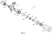
- FIG. 2 is an exploded view of the hemostasis valve 10.
- the hemostasis valve 10 may include a cartridge 20.
- the cartridge 20, which may include two pieces 20a, 20b that are coupled to one another (e.g., press fit, thermally bonded, adhesively bonded, etc.), may be arranged so that at least a portion thereof can be disposed within a proximal end region 22 of the main body 12.
- a first seal member 24 may be disposed within the cartridge 20.
- a second seal member 26 may be disposed within the proximal end region 22 of the main body 12. In at least some instances, the second seal member 26 may be disposed distally of the cartridge 20.
- the second seal member 26 may include a textured distal surface, grooves or wells formed therein, or the like. In addition or in the alternative, the second seal member 26 may include a proximal region with a reduced diameter. A nut 28 may be coupled to the proximal end region 22 of the main body 12, for example at one or more threads 30 formed along the proximal end region 22.
- the hemostasis valve 10 may include a spring member 32 and an O-ring 34.
- the spring member 32 may be coupled to the plunger 18. In at least some instances, the spring member 32 may be designed to exert a proximally directed force on the plunger 18.
- the O-ring 34 may be positioned adjacent to the adapter 16.
- a ring member or "snap ring" 36 may be disposed along the proximal end region 22 of the main body 12.
- FIG. 3 is a cross-sectional view the hemostasis valve 10.
- the hemostasis valve 10 may include a central lumen 38.
- the central lumen 38 is designed to be placed into fluid communication with one or more lumens of a device coupled to the adapter 16.
- a second or infusion lumen 4.0 may be defined adjacent to the side port 14.
- the second lumen 40 may be in fluid communication with the central lumen 38.
- the hemostasis valve 10 is designed so that it may be coupled to another device.
- the adapter 16 which may take the form of a Tuchy-Borst or other type of connector, may be engaged with the proximal end of the other device.
- the second seal member 26 When connected (and with the plunger 18 in the configuration shown in FIG. 3 the second seal member 26 may be in an open state or configuration.
- the first seal member 24 may be in a closed or sealed configuration when the hemostasis valve 10 is connected to the other device (and with the plunger 18 in the configuration shown in FIG. 3 ).
- the hemostasis valve 10 when the hemostasis valve 10 is connected to another device and in the configuration shown in FIG. 3 , the hemostasis valve 10 is able to substantially hold a fluid-tight seal that substantially prevents the backflow and/or leakage of body fluids (e.g., blood).
- body fluids e.g., blood
- the first seal member 24 may be designed to substantially prevent the backflow and/or leakage of relatively-low pressure fluids, if the infusion device infuses fluids at a relatively high pressure, it is possible that the infusion fluid may be able to flow through the first seal member 24.
- the hemostasis valve 10 can be actuated to close or "seal" the second seal member 26.
- the plunger 18 may initially be urged distally until a distally-facing, proximal end surface or cap 42 of the plunger 18 is disposed adjacent to a proximal end region 44 of the nut 28 as shown in FIG. 4 .
- a tubular region 46 of the plunger 18 may extend through (and open) the first seal member 24.
- a portion of the plunger 18 may move distally beyond the ring member 36.
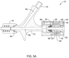
- the plunger 18 can be rotated (e.g., in a clockwise direction) to close the second seal member 26 as shown in FIG. 5A .
- This rotation may cause the nut 28 to rotate and move distally.
- distal movement of the nut 28 urges the cartridge 20 distally within the proximal end region 22 of the main body 12 such that the cartridge 20 engages and deforms the second seal member 26, thereby shifting the second seal member 26 to the closed or sealed configuration.
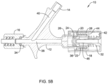
- the plunger 18 may be released or otherwise allowed to move proximally, as shown in FIG. 5B , which may reclose the first seal member 24 (while the second seal member 26 remains closed).
- the first seal member 24 may be described as a "low pressure" seal, designed to prevent the flow of fluids at a relatively low pressure.
- the first seal member 24 may be designed to withstand pressures on the order of about 517-586 kPa (75-85 pounds per square inch (psi)). While this performance is considered to be acceptable, it may desirable to further enhance the performance of the first seal member 24. Disclosed herein are hemostasis valves where the performance of the first seal member 24 is enhanced.
- FIG. 6 illustrates a portion of another example hemostasis valve 110 that may be similar in form and function to other hemostasis valve disclosed herein. While only a portion of the hemostasis valve 110 is shown, it can be appreciated that the reminder of the hemostasis valve 110 may include structures similar to or the same as those in the hemostasis valve 10 described above.
- the hemostasis valve 110 includes a main body 112 having a proximal end region 122.
- a cartridge 120 may be disposed at least partially within the proximal end region 122.
- the cartridge 120 may include a first seal member 124.
- a second seal member 126 may also be at least partially disposed within the proximal end region 122.
- a plunger 118 may be coupled to the proximal end region 122 and a nut 128 may be threadably engaged with the proximal end region 122.
- the plunger 118 may include an inner tubular region 148.
- the inner tubular region 148 may have a distal end 150.
- the distal end 150 of the inner tubular region 148 is designed to be arranged such that a clearance distance 152 is defined between the distal end 150 of the inner tubular region 148 and a proximal end or surface 154 of the first seal member 124.
- the clearance distance 152 is sufficiently small (e.g., on the order of about 0.1 to 5 mm or about 0.3 to 2 mm) so that when the first seal member 124 is exposed to elevated pressures, the proximal surface 154 of the first seal member 124 may slightly deform or shift into engagement with the distal end 150 of the inner tubular region 148 as shown in FIG. 7 . When doing so, the distal end 150 of the inner tubular region 148 may provide additional structural support such that the first seal member 124 is able to substantially remain sealed at higher pressures.
- the first seal member 124 may begin to deflect into engagement with the distal end 150 of the inner tubular region 14 when exposed to pressures of about 552-1724 kPa (80-250 pounds per square inch (psi)), or about 552-1379 kPa (80-200 psi), or about 689-1724 kPa (100-250 psi).
- pressures of about 552-1724 kPa (80-250 pounds per square inch (psi)), or about 552-1379 kPa (80-200 psi), or about 689-1724 kPa (100-250 psi).
- Such a deflection can be understood as a partial deflection or modification, which is different from a modification where the first seal member 124 is opened or otherwise permits the flow of fluids therethrough.
- the inner tubular region 148 may provide additional structural support to the first seal member 124 such that the first seal member 124 may be able to withstand pressures of about 689-3447 kPa (100-500 psi) or more, or about 1172-2758 kPa (170-400 psi) or more, or about 1724-1862 kPa (250-270 psi) or more.
- the inner tubular region 148 of the plunger 118 may be sized so as to bring the inner tubular region 148 into the desired proximity of the first seal member 124. This may include the inner tubular region 148 extending distally beyond the distal end of the plunger 118, the inner tubular region 148 extending to the distal end of the plunger, the inner tubular region 148 extending to a position that is proximal of the distal end of the plunger 118.
- the first seal member 124 may also be designed with structural features that provide the desired clearance distance 152.
- the cartridge 120 may include the first seal member 124 having an increased thickness, a reduced thickness, etc.
- the cartridge 120 may also be designed with structural features that provide the desired clearance distance 152.
- the cartridge 120 may be designed so that the position of the first seal member 124 therein may be shifted proximally or distally. Numerous other variations are contemplated.
- hemostasis valves similar to hemostasis valve 10 were manufactured without the plunger assembly attached. Tests were run to determine the amount of fluid pressure that could be applied until the first seal member began to leak fluid. It was determined that the average fluid pressure where leakage was observed for sample sterilized hemostasis valves at a time right after sterilization was 562.75 kPa (81.62 psi). It was also determined that the average fluid pressure where leakage was observed for sample sterilized hemostasis valves six months after sterilization was 551.44 kPa (79.98 psi).
- hemostasis valves similar to hemostasis valve 110 were manufactured. Tests were run to determine the amount of fluid pressure that could be applied until the first seal member began to leak fluid. No leakage was observed at pressures of 2068 kPa (300 psi), and leakage was not observed until pressures of 2758 kPa (400 psi) were applied.
- hemostasis valves similar to hemostasis valve 110 were manufactured. Tests were run to determine the amount of fluid pressure that could be applied until the first seal member began to leak fluid under differing conditions. It was determined that the average fluid pressure where leakage was observed for sample sterilized hemostasis valves after a single "plunge” (e.g., which can be understood to be a single actuation of the plunger where the plunger is moved distally, rotated clockwise in order to close the second seal member, rotated counter-clockwise to open the second seal member, and the moved proximally) was 1831.544 kPa (265.643 psi). It was also determined that after 50 "plunges", the average fluid pressure where leakage was observed was 1775.172 kPa (257.467 psi).
- the materials that can be used for the various components of the hemostasis valve 10 (and/or other hemostasis valves disclosed herein) and the various components thereof disclosed herein may include those commonly associated with medical devices.
- the following discussion makes reference to the main body 12 and other components of the hemostasis valve 10. However, this is not intended to limit the devices and methods described herein, as the discussion may be applied to other hemostasis valves and/or components thereof disclosed herein.
- the main body 12 and/or other components of the hemostasis valve 10 may be made from a metal, metal alloy, polymer (some examples of which are disclosed below), a metal-polymer composite, ceramics, combinations thereof, and the like, or other suitable material.
- suitable polymers may include polytetrafluoroethylene (PTFE), ethylene tetrafluoroethylene (ETFE), fluorinated ethylene propylene (FEP), polyoxymethylene (POM, for example, DELRIN ® available from DuPont), polyether block ester, polyurethane (for example, Polyurethane 85A), polypropylene (PP), polyvinylchloride (PVC), polyether-ester (for example, ARNITEL ® available from DSM Engineering Plastics), ether or ester based copolymers (for example, butylene/poly(alkylene ether) phthalate and/or other polyester elastomers such as HYTREL ® available from DuPont), polyamide (for example,
- suitable metals and metal alloys include stainless steel, such as 304V, 304L, and 316LV stainless steel; mild steel; nickel-titanium alloy such as linear-elastic and/or super-elastic nitinol; other nickel alloys such as nickel-chromium-molybdenum alloys (e.g., UNS: N06625 such as INCONEL ® 625, UNS: N06022 such as HASTELLOY ® C-22 ® , UNS: N10276 such as HASTELLOY ® C276 ® , other HASTELLOY ® alloys, and the like), nickel-copper alloys (e.g., UNS: N04400 such as MONEL ® 400, NICKELVAC ® 400, NICORROS ® 400, and the like), nickel-cobalt-chromium-molybdenum alloys (e.g., UNS: R30035 such as MP35-N ® and the like), nickel-co
- the first seal member 124 (and/or other seal members disclosed herein) may be formed from a suitable material.
- the seal member 124 may be formed from a silicone and/or silicone rubber material such as LSR6030, commercially available from Shenzhen SQUARE Silicone Co., Ltd.
- the seal member 124 may be formed from an elastomeric material such as Q7-4720, Q7-4735, GUMSTOCK, or the like, which are commercially available from DOW CORNING.
Landscapes
- Health & Medical Sciences (AREA)
- Heart & Thoracic Surgery (AREA)
- Pulmonology (AREA)
- Engineering & Computer Science (AREA)
- Anesthesiology (AREA)
- Biomedical Technology (AREA)
- Hematology (AREA)
- Life Sciences & Earth Sciences (AREA)
- Animal Behavior & Ethology (AREA)
- General Health & Medical Sciences (AREA)
- Public Health (AREA)
- Veterinary Medicine (AREA)
- Infusion, Injection, And Reservoir Apparatuses (AREA)
Claims (11)
- Hämostaseventil (10, 110), das aufweist:einen Hauptkörper (12, 112) mit einem proximalen Endbereich (22, 122);eine Hülse (20, 120), die mindestens teilweise im proximalen Endbereich (22, 122) angeordnet ist, wobei die Hülse (20, 120) ein Dichtungsteil (24, 124) aufweist;wobei das Dichtungsteil (24, 124) so gestaltet ist, dass es sich zwischen einer offenen Konfiguration und einer abgedichteten Konfiguration verschiebt;einen Kolben (18, 118), der mit dem proximalen Endbereich (22, 122) des Hauptkörpers (12, 112) gekoppelt ist, wobei der Kolben (18, 118) einen Innenröhrenbereich (46, 148) mit einem distalen Ende (150) hat;wobei das distale Ende (150) des Innenröhrenbereichs (46, 148) einen lichten Abstand (152) von einem proximalen Ende (154) des Dichtungsteils (24, 124) hat, so dass, wenn sich das Dichtungselement (24, 124) in der abgedichteten Konfiguration befindet und Drücken von etwa 552 kPa bis etwa 1724 kPa (etwa 80 bis etwa 250 Pounds pro Quadrat-Inch) ausgesetzt ist, sich das Dichtungsteil (24, 124) in Kontakt mit dem distalen Ende (150) des Innenröhrenbereichs (46, 148) ablenkt und in der abgedichteten Konfiguration bleibt.
- Hämostaseventil nach Anspruch 1, wobei der lichte Abstand (152) ein Axialmaß von etwa 0,1 bis etwa 5 Millimeter hat.
- Hämostaseventil nach Anspruch 1, wobei der lichte Abstand (152) ein Axialmaß von etwa 0,3 bis etwa 2 Millimeter hat.
- Hämostaseventil nach einem der Ansprüche 1 bis 3, wobei der lichte Abstand (152) so gestaltet ist, dass, wenn sich das Dichtungselement (24, 124) in der abgedichteten Konfiguration befindet und Drücken von etwa 689 kPa bis etwa 1724 kPa (etwa 100 bis etwa 250 Pounds pro Quadrat-Inch) ausgesetzt ist, sich das Dichtungsteil (24, 124) in Kontakt mit dem distalen Ende (150) des Innenröhrenbereichs (46, 148) ablenkt und in der abgedichteten Konfiguration bleibt.
- Hämostaseventil nach einem der Ansprüche 1 bis 4, wobei der lichte Abstand (152) so gestaltet ist, dass, wenn sich das Dichtungselement (24, 124) in der abgedichteten Konfiguration befindet und Drücken von etwa 552 kPa bis etwa 1379 kPa (etwa 80 bis etwa 200 Pounds pro Quadrat-Inch) ausgesetzt ist, sich das Dichtungsteil (24, 124) in Kontakt mit dem distalen Ende (150) des Innenröhrenbereichs ablenkt und in der abgedichteten Konfiguration bleibt.
- Hämostaseventil nach einem der Ansprüche 1 bis 5, wobei der proximale Endbereich (22, 122) des Hauptkörpers (12, 112) einen Haltevorsprung aufweist.
- Hämostaseventil nach Anspruch 6, wobei der Kolben (18, 118) einen distalen Halteflansch hat, der so gestaltet ist, dass er einen Eingriff mit dem Haltevorsprung herstellt.
- Hämostaseventil nach einem der Ansprüche 1 bis 7, wobei ein Federteil im Kolben (18, 118) angeordnet ist und in Eingriff mit einem proximalen Ende des Kolbens (18, 118) steht.
- Hämostaseventil nach einem der Ansprüche 1 bis 8, ferner mit einer Mutter (28, 128), die in Gewindeeingriff mit einem oder mehreren Gewinden entlang des proximalen Endbereichs (22, 122) des Hauptkörpers (12, 112) steht.
- Hämostaseventil nach einem der Ansprüche 1 bis 9, wobei der Innenröhrenbereich (46, 148) eine Wanddicke hat, die über seine Länge variiert.
- Hämostaseventil nach einem der Ansprüche 1 bis 10, wobei der Innenröhrenbereich (46, 148) einen Innendurchmesser hat, der über seine Länge variiert.
Applications Claiming Priority (2)
| Application Number | Priority Date | Filing Date | Title |
|---|---|---|---|
| US201762470677P | 2017-03-13 | 2017-03-13 | |
| PCT/US2018/019674 WO2018169664A1 (en) | 2017-03-13 | 2018-02-26 | Hemostasis valves and methods for making and using hemostasis valves |
Publications (2)
| Publication Number | Publication Date |
|---|---|
| EP3595767A1 EP3595767A1 (de) | 2020-01-22 |
| EP3595767B1 true EP3595767B1 (de) | 2025-06-18 |
Family
ID=61627172
Family Applications (1)
| Application Number | Title | Priority Date | Filing Date |
|---|---|---|---|
| EP18710955.8A Active EP3595767B1 (de) | 2017-03-13 | 2018-02-26 | Hämostaseventile und verfahren zur herstellung und verwendung von hämostaseventilen |
Country Status (4)
| Country | Link |
|---|---|
| US (1) | US10569072B2 (de) |
| EP (1) | EP3595767B1 (de) |
| CN (1) | CN110582324B (de) |
| WO (1) | WO2018169664A1 (de) |
Families Citing this family (7)
| Publication number | Priority date | Publication date | Assignee | Title |
|---|---|---|---|---|
| US20200316359A1 (en) * | 2019-04-04 | 2020-10-08 | Becton, Dickinson And Company | Multi-use blood control catheter assembly |
| US12311131B2 (en) | 2020-02-24 | 2025-05-27 | Becton, Dickinson And Company | Tubular instrument to reduce vein trauma and related devices and methods |
| US11304659B2 (en) | 2020-03-20 | 2022-04-19 | Xenter, Inc. | Operatively coupled data and power transfer device for medical guidewires and catheters with sensors |
| US20220161003A1 (en) * | 2020-11-26 | 2022-05-26 | Avia Vascular, Llc | Blood collection devices, systems, and methods |
| CN117062645A (zh) * | 2021-01-25 | 2023-11-14 | 海王星医疗公司 | 大直径止血阀 |
| US11992645B2 (en) * | 2022-02-10 | 2024-05-28 | St. Jude Medical, Cardiology Division, Inc. | Integrated hemostasis bypass valve |
| US12330292B2 (en) | 2023-09-28 | 2025-06-17 | Neptune Medical Inc. | Telescoping robot |
Family Cites Families (21)
| Publication number | Priority date | Publication date | Assignee | Title |
|---|---|---|---|---|
| US3180334A (en) | 1961-08-11 | 1965-04-27 | Lorena L Glenn | Enema retention cup |
| US4000739A (en) | 1975-07-09 | 1977-01-04 | Cordis Corporation | Hemostasis cannula |
| JPS6034241Y2 (ja) | 1977-04-25 | 1985-10-12 | オリンパス光学工業株式会社 | 内視鏡の通路気密装置 |
| US4177814A (en) | 1978-01-18 | 1979-12-11 | KLI, Incorporated | Self-sealing cannula |
| US4430081A (en) | 1981-01-06 | 1984-02-07 | Cook, Inc. | Hemostasis sheath |
| US4424833A (en) | 1981-10-02 | 1984-01-10 | C. R. Bard, Inc. | Self sealing gasket assembly |
| US4726374A (en) * | 1985-12-09 | 1988-02-23 | Cordis Corporation | Leakproof hemostasis valve |
| US5489274A (en) * | 1992-10-09 | 1996-02-06 | Boston Scientific Corporation | Rotatable medical valve closure |
| US5330435A (en) * | 1993-04-08 | 1994-07-19 | Vaillancourt Vincent L | Valve for a catheter assembly |
| US5591137A (en) * | 1995-07-14 | 1997-01-07 | Merit Medical Systems, Inc. | Hemostasis valve with locking seal |
| WO1998013083A1 (en) * | 1996-09-26 | 1998-04-02 | Symbiosis Corporation | Catheter sheath introducer with improved hemostasis valve |
| US7226433B2 (en) | 1998-02-06 | 2007-06-05 | Possis Medical, Inc. | Thrombectomy catheter device having a self-sealing hemostasis valve |
| US6402723B1 (en) | 1999-04-16 | 2002-06-11 | Merit Medical Systems, Inc. | Inline hemostasis valve |
| AU8037600A (en) | 1999-09-07 | 2001-04-10 | Merit Medical Systems, Inc. | Hemostasis valve apparatus with integral introducer |
| DE602004027740D1 (de) * | 2003-08-26 | 2010-07-29 | Zerusa Ltd | Hämostasevorrichtung |
| US9623228B2 (en) * | 2010-08-12 | 2017-04-18 | Silk Road Medical, Inc. | Systems and methods for treating a carotid artery |
| WO2013047205A1 (ja) * | 2011-09-28 | 2013-04-04 | テルモ株式会社 | カテーテル組立体 |
| CN202654537U (zh) * | 2012-05-31 | 2013-01-09 | 广州曼翔医疗器械有限公司 | 旋压组合式止血阀 |
| JP6083850B2 (ja) * | 2012-08-24 | 2017-02-22 | 株式会社グッドマン | 医療用弁装置 |
| CN104800954B (zh) * | 2015-05-20 | 2017-10-13 | 湖南埃普特医疗器械有限公司 | 一种可调阀导管鞘 |
| CN113017767A (zh) * | 2016-06-08 | 2021-06-25 | 深圳市科奕顿生物医疗科技有限公司 | 一种介入医疗器械输送系统及输送方法 |
-
2018
- 2018-02-26 WO PCT/US2018/019674 patent/WO2018169664A1/en not_active Ceased
- 2018-02-26 EP EP18710955.8A patent/EP3595767B1/de active Active
- 2018-02-26 CN CN201880029627.6A patent/CN110582324B/zh active Active
- 2018-02-26 US US15/904,829 patent/US10569072B2/en active Active
Also Published As
| Publication number | Publication date |
|---|---|
| CN110582324B (zh) | 2022-04-15 |
| EP3595767A1 (de) | 2020-01-22 |
| WO2018169664A1 (en) | 2018-09-20 |
| CN110582324A (zh) | 2019-12-17 |
| US10569072B2 (en) | 2020-02-25 |
| US20180256872A1 (en) | 2018-09-13 |
Similar Documents
| Publication | Publication Date | Title |
|---|---|---|
| US10953214B2 (en) | Hemostasis valves and methods for making and using hemostasis valves | |
| EP3595767B1 (de) | Hämostaseventile und verfahren zur herstellung und verwendung von hämostaseventilen | |
| EP3595765B1 (de) | Hämostaseventile und verfahren zur herstellung und verwendung von hämostaseventilen | |
| US11291821B2 (en) | Hemostasis valves and methods for making and using hemostasis valves | |
| US10842981B2 (en) | Hemostasis valves and methods for making and using hemostasis valves | |
| US12178983B2 (en) | Low pressure seal design for a hemostasis valve | |
| US11129969B2 (en) | Loading tools for use with medical devices | |
| US10960501B2 (en) | Hemostasis valves and methods for making and using hemostasis valves | |
| US20250195786A1 (en) | Devices for use with a syringe |
Legal Events
| Date | Code | Title | Description |
|---|---|---|---|
| STAA | Information on the status of an ep patent application or granted ep patent |
Free format text: STATUS: UNKNOWN |
|
| STAA | Information on the status of an ep patent application or granted ep patent |
Free format text: STATUS: THE INTERNATIONAL PUBLICATION HAS BEEN MADE |
|
| PUAI | Public reference made under article 153(3) epc to a published international application that has entered the european phase |
Free format text: ORIGINAL CODE: 0009012 |
|
| STAA | Information on the status of an ep patent application or granted ep patent |
Free format text: STATUS: REQUEST FOR EXAMINATION WAS MADE |
|
| 17P | Request for examination filed |
Effective date: 20191012 |
|
| AK | Designated contracting states |
Kind code of ref document: A1 Designated state(s): AL AT BE BG CH CY CZ DE DK EE ES FI FR GB GR HR HU IE IS IT LI LT LU LV MC MK MT NL NO PL PT RO RS SE SI SK SM TR |
|
| AX | Request for extension of the european patent |
Extension state: BA ME |
|
| DAV | Request for validation of the european patent (deleted) | ||
| DAX | Request for extension of the european patent (deleted) | ||
| RAP1 | Party data changed (applicant data changed or rights of an application transferred) |
Owner name: BOSTON SCIENTIFIC MEDICAL DEVICE LIMITED |
|
| STAA | Information on the status of an ep patent application or granted ep patent |
Free format text: STATUS: EXAMINATION IS IN PROGRESS |
|
| 17Q | First examination report despatched |
Effective date: 20240416 |
|
| GRAP | Despatch of communication of intention to grant a patent |
Free format text: ORIGINAL CODE: EPIDOSNIGR1 |
|
| STAA | Information on the status of an ep patent application or granted ep patent |
Free format text: STATUS: GRANT OF PATENT IS INTENDED |
|
| INTG | Intention to grant announced |
Effective date: 20250217 |
|
| GRAS | Grant fee paid |
Free format text: ORIGINAL CODE: EPIDOSNIGR3 |
|
| GRAA | (expected) grant |
Free format text: ORIGINAL CODE: 0009210 |
|
| STAA | Information on the status of an ep patent application or granted ep patent |
Free format text: STATUS: THE PATENT HAS BEEN GRANTED |
|
| AK | Designated contracting states |
Kind code of ref document: B1 Designated state(s): AL AT BE BG CH CY CZ DE DK EE ES FI FR GB GR HR HU IE IS IT LI LT LU LV MC MK MT NL NO PL PT RO RS SE SI SK SM TR |
|
| REG | Reference to a national code |
Ref country code: GB Ref legal event code: FG4D |
|
| REG | Reference to a national code |
Ref country code: CH Ref legal event code: EP |
|
| REG | Reference to a national code |
Ref country code: DE Ref legal event code: R096 Ref document number: 602018082642 Country of ref document: DE |
|
| REG | Reference to a national code |
Ref country code: CH Ref legal event code: EP |
|
| REG | Reference to a national code |
Ref country code: IE Ref legal event code: FG4D |
|
| REG | Reference to a national code |
Ref country code: NL Ref legal event code: FP |
|
| PG25 | Lapsed in a contracting state [announced via postgrant information from national office to epo] |
Ref country code: FI Free format text: LAPSE BECAUSE OF FAILURE TO SUBMIT A TRANSLATION OF THE DESCRIPTION OR TO PAY THE FEE WITHIN THE PRESCRIBED TIME-LIMIT Effective date: 20250618 |
|
| REG | Reference to a national code |
Ref country code: LT Ref legal event code: MG9D |
|
| PG25 | Lapsed in a contracting state [announced via postgrant information from national office to epo] |
Ref country code: NO Free format text: LAPSE BECAUSE OF FAILURE TO SUBMIT A TRANSLATION OF THE DESCRIPTION OR TO PAY THE FEE WITHIN THE PRESCRIBED TIME-LIMIT Effective date: 20250918 Ref country code: GR Free format text: LAPSE BECAUSE OF FAILURE TO SUBMIT A TRANSLATION OF THE DESCRIPTION OR TO PAY THE FEE WITHIN THE PRESCRIBED TIME-LIMIT Effective date: 20250919 |
|
| PG25 | Lapsed in a contracting state [announced via postgrant information from national office to epo] |
Ref country code: BG Free format text: LAPSE BECAUSE OF FAILURE TO SUBMIT A TRANSLATION OF THE DESCRIPTION OR TO PAY THE FEE WITHIN THE PRESCRIBED TIME-LIMIT Effective date: 20250618 |
|
| PG25 | Lapsed in a contracting state [announced via postgrant information from national office to epo] |
Ref country code: HR Free format text: LAPSE BECAUSE OF FAILURE TO SUBMIT A TRANSLATION OF THE DESCRIPTION OR TO PAY THE FEE WITHIN THE PRESCRIBED TIME-LIMIT Effective date: 20250618 |
|
| PG25 | Lapsed in a contracting state [announced via postgrant information from national office to epo] |
Ref country code: RS Free format text: LAPSE BECAUSE OF FAILURE TO SUBMIT A TRANSLATION OF THE DESCRIPTION OR TO PAY THE FEE WITHIN THE PRESCRIBED TIME-LIMIT Effective date: 20250918 |
|
| PG25 | Lapsed in a contracting state [announced via postgrant information from national office to epo] |
Ref country code: LV Free format text: LAPSE BECAUSE OF FAILURE TO SUBMIT A TRANSLATION OF THE DESCRIPTION OR TO PAY THE FEE WITHIN THE PRESCRIBED TIME-LIMIT Effective date: 20250618 |
|
| PG25 | Lapsed in a contracting state [announced via postgrant information from national office to epo] |
Ref country code: PT Free format text: LAPSE BECAUSE OF FAILURE TO SUBMIT A TRANSLATION OF THE DESCRIPTION OR TO PAY THE FEE WITHIN THE PRESCRIBED TIME-LIMIT Effective date: 20251020 |
|
| REG | Reference to a national code |
Ref country code: AT Ref legal event code: MK05 Ref document number: 1803657 Country of ref document: AT Kind code of ref document: T Effective date: 20250618 |
|
| PG25 | Lapsed in a contracting state [announced via postgrant information from national office to epo] |
Ref country code: IS Free format text: LAPSE BECAUSE OF FAILURE TO SUBMIT A TRANSLATION OF THE DESCRIPTION OR TO PAY THE FEE WITHIN THE PRESCRIBED TIME-LIMIT Effective date: 20251018 |
|
| PG25 | Lapsed in a contracting state [announced via postgrant information from national office to epo] |
Ref country code: AT Free format text: LAPSE BECAUSE OF FAILURE TO SUBMIT A TRANSLATION OF THE DESCRIPTION OR TO PAY THE FEE WITHIN THE PRESCRIBED TIME-LIMIT Effective date: 20250618 Ref country code: SM Free format text: LAPSE BECAUSE OF FAILURE TO SUBMIT A TRANSLATION OF THE DESCRIPTION OR TO PAY THE FEE WITHIN THE PRESCRIBED TIME-LIMIT Effective date: 20250618 |
|
| PG25 | Lapsed in a contracting state [announced via postgrant information from national office to epo] |
Ref country code: CZ Free format text: LAPSE BECAUSE OF FAILURE TO SUBMIT A TRANSLATION OF THE DESCRIPTION OR TO PAY THE FEE WITHIN THE PRESCRIBED TIME-LIMIT Effective date: 20250618 |
|
| PG25 | Lapsed in a contracting state [announced via postgrant information from national office to epo] |
Ref country code: PL Free format text: LAPSE BECAUSE OF FAILURE TO SUBMIT A TRANSLATION OF THE DESCRIPTION OR TO PAY THE FEE WITHIN THE PRESCRIBED TIME-LIMIT Effective date: 20250618 |
|
| PG25 | Lapsed in a contracting state [announced via postgrant information from national office to epo] |
Ref country code: EE Free format text: LAPSE BECAUSE OF FAILURE TO SUBMIT A TRANSLATION OF THE DESCRIPTION OR TO PAY THE FEE WITHIN THE PRESCRIBED TIME-LIMIT Effective date: 20250618 |
|
| PG25 | Lapsed in a contracting state [announced via postgrant information from national office to epo] |
Ref country code: RO Free format text: LAPSE BECAUSE OF FAILURE TO SUBMIT A TRANSLATION OF THE DESCRIPTION OR TO PAY THE FEE WITHIN THE PRESCRIBED TIME-LIMIT Effective date: 20250618 Ref country code: SK Free format text: LAPSE BECAUSE OF FAILURE TO SUBMIT A TRANSLATION OF THE DESCRIPTION OR TO PAY THE FEE WITHIN THE PRESCRIBED TIME-LIMIT Effective date: 20250618 |
|
| PG25 | Lapsed in a contracting state [announced via postgrant information from national office to epo] |
Ref country code: ES Free format text: LAPSE BECAUSE OF FAILURE TO SUBMIT A TRANSLATION OF THE DESCRIPTION OR TO PAY THE FEE WITHIN THE PRESCRIBED TIME-LIMIT Effective date: 20250618 |
|
| PGFP | Annual fee paid to national office [announced via postgrant information from national office to epo] |
Ref country code: NL Payment date: 20260121 Year of fee payment: 9 |
|
| PG25 | Lapsed in a contracting state [announced via postgrant information from national office to epo] |
Ref country code: DK Free format text: LAPSE BECAUSE OF FAILURE TO SUBMIT A TRANSLATION OF THE DESCRIPTION OR TO PAY THE FEE WITHIN THE PRESCRIBED TIME-LIMIT Effective date: 20250618 |
|
| PGFP | Annual fee paid to national office [announced via postgrant information from national office to epo] |
Ref country code: DE Payment date: 20260121 Year of fee payment: 9 Ref country code: IE Payment date: 20260123 Year of fee payment: 9 |
|
| PG25 | Lapsed in a contracting state [announced via postgrant information from national office to epo] |
Ref country code: IT Free format text: LAPSE BECAUSE OF FAILURE TO SUBMIT A TRANSLATION OF THE DESCRIPTION OR TO PAY THE FEE WITHIN THE PRESCRIBED TIME-LIMIT Effective date: 20250618 |
|
| PLBE | No opposition filed within time limit |
Free format text: ORIGINAL CODE: 0009261 |
|
| STAA | Information on the status of an ep patent application or granted ep patent |
Free format text: STATUS: NO OPPOSITION FILED WITHIN TIME LIMIT |