EP3595074A1 - Secondary battery - Google Patents
Secondary battery Download PDFInfo
- Publication number
- EP3595074A1 EP3595074A1 EP17899846.4A EP17899846A EP3595074A1 EP 3595074 A1 EP3595074 A1 EP 3595074A1 EP 17899846 A EP17899846 A EP 17899846A EP 3595074 A1 EP3595074 A1 EP 3595074A1
- Authority
- EP
- European Patent Office
- Prior art keywords
- negative electrode
- material layer
- section
- contact
- active material
- Prior art date
- Legal status (The legal status is an assumption and is not a legal conclusion. Google has not performed a legal analysis and makes no representation as to the accuracy of the status listed.)
- Granted
Links
- 239000007773 negative electrode material Substances 0.000 claims abstract description 48
- 230000008602 contraction Effects 0.000 claims abstract description 31
- 230000000452 restraining effect Effects 0.000 claims abstract description 31
- 238000010248 power generation Methods 0.000 claims abstract description 25
- 238000007599 discharging Methods 0.000 claims abstract description 9
- 230000008859 change Effects 0.000 claims abstract description 5
- 239000000463 material Substances 0.000 claims description 95
- 239000000853 adhesive Substances 0.000 claims description 79
- 230000001070 adhesive effect Effects 0.000 claims description 79
- 239000007774 positive electrode material Substances 0.000 claims description 39
- 239000003792 electrolyte Substances 0.000 claims description 15
- 239000004820 Pressure-sensitive adhesive Substances 0.000 claims description 11
- 229910052710 silicon Inorganic materials 0.000 claims description 9
- 239000010703 silicon Substances 0.000 claims description 9
- 239000011887 silicon containing negative electrode material Substances 0.000 abstract description 6
- 239000011149 active material Substances 0.000 description 19
- 230000004048 modification Effects 0.000 description 19
- 238000012986 modification Methods 0.000 description 19
- PXHVJJICTQNCMI-UHFFFAOYSA-N Nickel Chemical compound [Ni] PXHVJJICTQNCMI-UHFFFAOYSA-N 0.000 description 12
- XUIMIQQOPSSXEZ-UHFFFAOYSA-N Silicon Chemical compound [Si] XUIMIQQOPSSXEZ-UHFFFAOYSA-N 0.000 description 9
- HBBGRARXTFLTSG-UHFFFAOYSA-N Lithium ion Chemical compound [Li+] HBBGRARXTFLTSG-UHFFFAOYSA-N 0.000 description 8
- 229910001416 lithium ion Inorganic materials 0.000 description 8
- -1 polypropylene Polymers 0.000 description 8
- OKTJSMMVPCPJKN-UHFFFAOYSA-N Carbon Chemical compound [C] OKTJSMMVPCPJKN-UHFFFAOYSA-N 0.000 description 7
- 239000011230 binding agent Substances 0.000 description 7
- RYGMFSIKBFXOCR-UHFFFAOYSA-N Copper Chemical compound [Cu] RYGMFSIKBFXOCR-UHFFFAOYSA-N 0.000 description 6
- 239000002033 PVDF binder Substances 0.000 description 6
- VYPSYNLAJGMNEJ-UHFFFAOYSA-N Silicium dioxide Chemical compound O=[Si]=O VYPSYNLAJGMNEJ-UHFFFAOYSA-N 0.000 description 6
- 229910052782 aluminium Inorganic materials 0.000 description 6
- XAGFODPZIPBFFR-UHFFFAOYSA-N aluminium Chemical compound [Al] XAGFODPZIPBFFR-UHFFFAOYSA-N 0.000 description 6
- 239000011883 electrode binding agent Substances 0.000 description 6
- 229910052759 nickel Inorganic materials 0.000 description 6
- 229920002981 polyvinylidene fluoride Polymers 0.000 description 6
- 239000004743 Polypropylene Substances 0.000 description 5
- 229910052802 copper Inorganic materials 0.000 description 5
- 239000010949 copper Substances 0.000 description 5
- 229910052751 metal Inorganic materials 0.000 description 5
- 239000002184 metal Substances 0.000 description 5
- 229920001155 polypropylene Polymers 0.000 description 5
- 239000002210 silicon-based material Substances 0.000 description 5
- RTAQQCXQSZGOHL-UHFFFAOYSA-N Titanium Chemical compound [Ti] RTAQQCXQSZGOHL-UHFFFAOYSA-N 0.000 description 4
- 239000000654 additive Substances 0.000 description 4
- 229910045601 alloy Inorganic materials 0.000 description 4
- 239000000956 alloy Substances 0.000 description 4
- 239000011244 liquid electrolyte Substances 0.000 description 4
- 239000000203 mixture Substances 0.000 description 4
- 229920001721 polyimide Polymers 0.000 description 4
- 229920000642 polymer Polymers 0.000 description 4
- 229910052814 silicon oxide Inorganic materials 0.000 description 4
- 229920003048 styrene butadiene rubber Polymers 0.000 description 4
- 239000010936 titanium Substances 0.000 description 4
- 229910052719 titanium Inorganic materials 0.000 description 4
- 229920002134 Carboxymethyl cellulose Polymers 0.000 description 3
- 239000004698 Polyethylene Substances 0.000 description 3
- 239000004642 Polyimide Substances 0.000 description 3
- 229910000676 Si alloy Inorganic materials 0.000 description 3
- 239000006230 acetylene black Substances 0.000 description 3
- 238000005253 cladding Methods 0.000 description 3
- 239000000470 constituent Substances 0.000 description 3
- 239000005001 laminate film Substances 0.000 description 3
- 238000000034 method Methods 0.000 description 3
- 229920000573 polyethylene Polymers 0.000 description 3
- 239000002861 polymer material Substances 0.000 description 3
- 229920000098 polyolefin Polymers 0.000 description 3
- 239000011148 porous material Substances 0.000 description 3
- 239000002904 solvent Substances 0.000 description 3
- 239000010935 stainless steel Substances 0.000 description 3
- 229910001220 stainless steel Inorganic materials 0.000 description 3
- ZZXUZKXVROWEIF-UHFFFAOYSA-N 1,2-butylene carbonate Chemical compound CCC1COC(=O)O1 ZZXUZKXVROWEIF-UHFFFAOYSA-N 0.000 description 2
- VAYTZRYEBVHVLE-UHFFFAOYSA-N 1,3-dioxol-2-one Chemical compound O=C1OC=CO1 VAYTZRYEBVHVLE-UHFFFAOYSA-N 0.000 description 2
- OIFBSDVPJOWBCH-UHFFFAOYSA-N Diethyl carbonate Chemical compound CCOC(=O)OCC OIFBSDVPJOWBCH-UHFFFAOYSA-N 0.000 description 2
- KMTRUDSVKNLOMY-UHFFFAOYSA-N Ethylene carbonate Chemical group O=C1OCCO1 KMTRUDSVKNLOMY-UHFFFAOYSA-N 0.000 description 2
- XEEYBQQBJWHFJM-UHFFFAOYSA-N Iron Chemical compound [Fe] XEEYBQQBJWHFJM-UHFFFAOYSA-N 0.000 description 2
- 229910015020 LiNiCoAlO2 Inorganic materials 0.000 description 2
- WHXSMMKQMYFTQS-UHFFFAOYSA-N Lithium Chemical compound [Li] WHXSMMKQMYFTQS-UHFFFAOYSA-N 0.000 description 2
- FYYHWMGAXLPEAU-UHFFFAOYSA-N Magnesium Chemical compound [Mg] FYYHWMGAXLPEAU-UHFFFAOYSA-N 0.000 description 2
- 229920003171 Poly (ethylene oxide) Polymers 0.000 description 2
- ATJFFYVFTNAWJD-UHFFFAOYSA-N Tin Chemical compound [Sn] ATJFFYVFTNAWJD-UHFFFAOYSA-N 0.000 description 2
- HCHKCACWOHOZIP-UHFFFAOYSA-N Zinc Chemical compound [Zn] HCHKCACWOHOZIP-UHFFFAOYSA-N 0.000 description 2
- 229920003235 aromatic polyamide Polymers 0.000 description 2
- 239000002134 carbon nanofiber Substances 0.000 description 2
- 239000003575 carbonaceous material Substances 0.000 description 2
- 229920001940 conductive polymer Polymers 0.000 description 2
- 230000000694 effects Effects 0.000 description 2
- 229920001971 elastomer Polymers 0.000 description 2
- JBTWLSYIZRCDFO-UHFFFAOYSA-N ethyl methyl carbonate Chemical compound CCOC(=O)OC JBTWLSYIZRCDFO-UHFFFAOYSA-N 0.000 description 2
- 239000000945 filler Substances 0.000 description 2
- 229910002804 graphite Inorganic materials 0.000 description 2
- 239000010439 graphite Substances 0.000 description 2
- 229910052744 lithium Inorganic materials 0.000 description 2
- 229910003002 lithium salt Inorganic materials 0.000 description 2
- 159000000002 lithium salts Chemical class 0.000 description 2
- 229910052749 magnesium Inorganic materials 0.000 description 2
- 239000011777 magnesium Substances 0.000 description 2
- 239000011159 matrix material Substances 0.000 description 2
- KKQAVHGECIBFRQ-UHFFFAOYSA-N methyl propyl carbonate Chemical compound CCCOC(=O)OC KKQAVHGECIBFRQ-UHFFFAOYSA-N 0.000 description 2
- 239000004745 nonwoven fabric Substances 0.000 description 2
- 230000002093 peripheral effect Effects 0.000 description 2
- 239000005518 polymer electrolyte Substances 0.000 description 2
- 229920001451 polypropylene glycol Polymers 0.000 description 2
- RUOJZAUFBMNUDX-UHFFFAOYSA-N propylene carbonate Chemical compound CC1COC(=O)O1 RUOJZAUFBMNUDX-UHFFFAOYSA-N 0.000 description 2
- 229920005989 resin Polymers 0.000 description 2
- 239000011347 resin Substances 0.000 description 2
- 230000000717 retained effect Effects 0.000 description 2
- 239000005060 rubber Substances 0.000 description 2
- 150000003377 silicon compounds Chemical class 0.000 description 2
- LIVNPJMFVYWSIS-UHFFFAOYSA-N silicon monoxide Chemical compound [Si-]#[O+] LIVNPJMFVYWSIS-UHFFFAOYSA-N 0.000 description 2
- 229910052718 tin Inorganic materials 0.000 description 2
- 239000011135 tin Substances 0.000 description 2
- 229910052720 vanadium Inorganic materials 0.000 description 2
- LEONUFNNVUYDNQ-UHFFFAOYSA-N vanadium atom Chemical compound [V] LEONUFNNVUYDNQ-UHFFFAOYSA-N 0.000 description 2
- 238000003466 welding Methods 0.000 description 2
- 229910052725 zinc Inorganic materials 0.000 description 2
- 239000011701 zinc Substances 0.000 description 2
- QTBSBXVTEAMEQO-UHFFFAOYSA-M Acetate Chemical compound CC([O-])=O QTBSBXVTEAMEQO-UHFFFAOYSA-M 0.000 description 1
- 229920000049 Carbon (fiber) Polymers 0.000 description 1
- 229920000742 Cotton Polymers 0.000 description 1
- 229910007003 Li(C2F5SO2)2 Inorganic materials 0.000 description 1
- 229910001560 Li(CF3SO2)2N Inorganic materials 0.000 description 1
- 229910000552 LiCF3SO3 Inorganic materials 0.000 description 1
- 229910032387 LiCoO2 Inorganic materials 0.000 description 1
- 229910052493 LiFePO4 Inorganic materials 0.000 description 1
- 229910003005 LiNiO2 Inorganic materials 0.000 description 1
- 229910001290 LiPF6 Inorganic materials 0.000 description 1
- 229910012464 LiTaF6 Inorganic materials 0.000 description 1
- 229910002097 Lithium manganese(III,IV) oxide Inorganic materials 0.000 description 1
- 229920000297 Rayon Polymers 0.000 description 1
- 229910008350 Si-Sn-Ti Inorganic materials 0.000 description 1
- 229910006721 Si—Sn—Ti Inorganic materials 0.000 description 1
- 229920002125 Sokalan® Polymers 0.000 description 1
- NIXOWILDQLNWCW-UHFFFAOYSA-N acrylic acid group Chemical group C(C=C)(=O)O NIXOWILDQLNWCW-UHFFFAOYSA-N 0.000 description 1
- JRBRVDCKNXZZGH-UHFFFAOYSA-N alumane;copper Chemical compound [AlH3].[Cu] JRBRVDCKNXZZGH-UHFFFAOYSA-N 0.000 description 1
- 229910021486 amorphous silicon dioxide Inorganic materials 0.000 description 1
- 230000004888 barrier function Effects 0.000 description 1
- 229910052799 carbon Inorganic materials 0.000 description 1
- 239000004917 carbon fiber Substances 0.000 description 1
- 230000015556 catabolic process Effects 0.000 description 1
- 238000006243 chemical reaction Methods 0.000 description 1
- 229910052681 coesite Inorganic materials 0.000 description 1
- 229920001577 copolymer Polymers 0.000 description 1
- 239000011889 copper foil Substances 0.000 description 1
- 229910052906 cristobalite Inorganic materials 0.000 description 1
- 238000006731 degradation reaction Methods 0.000 description 1
- 230000006866 deterioration Effects 0.000 description 1
- IEJIGPNLZYLLBP-UHFFFAOYSA-N dimethyl carbonate Chemical compound COC(=O)OC IEJIGPNLZYLLBP-UHFFFAOYSA-N 0.000 description 1
- 238000001035 drying Methods 0.000 description 1
- 239000007772 electrode material Substances 0.000 description 1
- 239000008151 electrolyte solution Substances 0.000 description 1
- 238000005516 engineering process Methods 0.000 description 1
- 230000007613 environmental effect Effects 0.000 description 1
- 230000004927 fusion Effects 0.000 description 1
- 239000003365 glass fiber Substances 0.000 description 1
- 150000002500 ions Chemical class 0.000 description 1
- 229910052742 iron Inorganic materials 0.000 description 1
- 239000007788 liquid Substances 0.000 description 1
- 229910001540 lithium hexafluoroarsenate(V) Inorganic materials 0.000 description 1
- MHCFAGZWMAWTNR-UHFFFAOYSA-M lithium perchlorate Chemical compound [Li+].[O-]Cl(=O)(=O)=O MHCFAGZWMAWTNR-UHFFFAOYSA-M 0.000 description 1
- 229910001486 lithium perchlorate Inorganic materials 0.000 description 1
- 229910001496 lithium tetrafluoroborate Inorganic materials 0.000 description 1
- 239000002905 metal composite material Substances 0.000 description 1
- 150000002739 metals Chemical class 0.000 description 1
- 229910001317 nickel manganese cobalt oxide (NMC) Inorganic materials 0.000 description 1
- 229920001778 nylon Polymers 0.000 description 1
- 125000004430 oxygen atom Chemical group O* 0.000 description 1
- 239000002245 particle Substances 0.000 description 1
- 229920003223 poly(pyromellitimide-1,4-diphenyl ether) Polymers 0.000 description 1
- 229920005569 poly(vinylidene fluoride-co-hexafluoropropylene) Polymers 0.000 description 1
- 239000004584 polyacrylic acid Substances 0.000 description 1
- 229920000728 polyester Polymers 0.000 description 1
- 239000002964 rayon Substances 0.000 description 1
- 230000004044 response Effects 0.000 description 1
- 239000004065 semiconductor Substances 0.000 description 1
- 230000035939 shock Effects 0.000 description 1
- 239000000377 silicon dioxide Substances 0.000 description 1
- 239000011856 silicon-based particle Substances 0.000 description 1
- 229910052682 stishovite Inorganic materials 0.000 description 1
- 239000003115 supporting electrolyte Substances 0.000 description 1
- 229920005992 thermoplastic resin Polymers 0.000 description 1
- 229910052905 tridymite Inorganic materials 0.000 description 1
- 229920003169 water-soluble polymer Polymers 0.000 description 1
- 239000013585 weight reducing agent Substances 0.000 description 1
Images


Classifications
-
- H—ELECTRICITY
- H01—ELECTRIC ELEMENTS
- H01M—PROCESSES OR MEANS, e.g. BATTERIES, FOR THE DIRECT CONVERSION OF CHEMICAL ENERGY INTO ELECTRICAL ENERGY
- H01M50/00—Constructional details or processes of manufacture of the non-active parts of electrochemical cells other than fuel cells, e.g. hybrid cells
- H01M50/50—Current conducting connections for cells or batteries
- H01M50/572—Means for preventing undesired use or discharge
- H01M50/574—Devices or arrangements for the interruption of current
- H01M50/578—Devices or arrangements for the interruption of current in response to pressure
-
- H—ELECTRICITY
- H01—ELECTRIC ELEMENTS
- H01M—PROCESSES OR MEANS, e.g. BATTERIES, FOR THE DIRECT CONVERSION OF CHEMICAL ENERGY INTO ELECTRICAL ENERGY
- H01M10/00—Secondary cells; Manufacture thereof
- H01M10/04—Construction or manufacture in general
- H01M10/0468—Compression means for stacks of electrodes and separators
-
- H—ELECTRICITY
- H01—ELECTRIC ELEMENTS
- H01M—PROCESSES OR MEANS, e.g. BATTERIES, FOR THE DIRECT CONVERSION OF CHEMICAL ENERGY INTO ELECTRICAL ENERGY
- H01M10/00—Secondary cells; Manufacture thereof
- H01M10/05—Accumulators with non-aqueous electrolyte
- H01M10/052—Li-accumulators
- H01M10/0525—Rocking-chair batteries, i.e. batteries with lithium insertion or intercalation in both electrodes; Lithium-ion batteries
-
- H—ELECTRICITY
- H01—ELECTRIC ELEMENTS
- H01M—PROCESSES OR MEANS, e.g. BATTERIES, FOR THE DIRECT CONVERSION OF CHEMICAL ENERGY INTO ELECTRICAL ENERGY
- H01M10/00—Secondary cells; Manufacture thereof
- H01M10/05—Accumulators with non-aqueous electrolyte
- H01M10/058—Construction or manufacture
- H01M10/0585—Construction or manufacture of accumulators having only flat construction elements, i.e. flat positive electrodes, flat negative electrodes and flat separators
-
- H—ELECTRICITY
- H01—ELECTRIC ELEMENTS
- H01M—PROCESSES OR MEANS, e.g. BATTERIES, FOR THE DIRECT CONVERSION OF CHEMICAL ENERGY INTO ELECTRICAL ENERGY
- H01M4/00—Electrodes
- H01M4/02—Electrodes composed of, or comprising, active material
- H01M4/13—Electrodes for accumulators with non-aqueous electrolyte, e.g. for lithium-accumulators; Processes of manufacture thereof
- H01M4/134—Electrodes based on metals, Si or alloys
-
- H—ELECTRICITY
- H01—ELECTRIC ELEMENTS
- H01M—PROCESSES OR MEANS, e.g. BATTERIES, FOR THE DIRECT CONVERSION OF CHEMICAL ENERGY INTO ELECTRICAL ENERGY
- H01M4/00—Electrodes
- H01M4/02—Electrodes composed of, or comprising, active material
- H01M4/36—Selection of substances as active materials, active masses, active liquids
- H01M4/38—Selection of substances as active materials, active masses, active liquids of elements or alloys
- H01M4/386—Silicon or alloys based on silicon
-
- H—ELECTRICITY
- H01—ELECTRIC ELEMENTS
- H01M—PROCESSES OR MEANS, e.g. BATTERIES, FOR THE DIRECT CONVERSION OF CHEMICAL ENERGY INTO ELECTRICAL ENERGY
- H01M4/00—Electrodes
- H01M4/02—Electrodes composed of, or comprising, active material
- H01M4/62—Selection of inactive substances as ingredients for active masses, e.g. binders, fillers
- H01M4/627—Expanders for lead-acid accumulators
-
- H—ELECTRICITY
- H01—ELECTRIC ELEMENTS
- H01M—PROCESSES OR MEANS, e.g. BATTERIES, FOR THE DIRECT CONVERSION OF CHEMICAL ENERGY INTO ELECTRICAL ENERGY
- H01M50/00—Constructional details or processes of manufacture of the non-active parts of electrochemical cells other than fuel cells, e.g. hybrid cells
- H01M50/40—Separators; Membranes; Diaphragms; Spacing elements inside cells
- H01M50/46—Separators, membranes or diaphragms characterised by their combination with electrodes
- H01M50/461—Separators, membranes or diaphragms characterised by their combination with electrodes with adhesive layers between electrodes and separators
-
- H—ELECTRICITY
- H01—ELECTRIC ELEMENTS
- H01M—PROCESSES OR MEANS, e.g. BATTERIES, FOR THE DIRECT CONVERSION OF CHEMICAL ENERGY INTO ELECTRICAL ENERGY
- H01M10/00—Secondary cells; Manufacture thereof
- H01M10/04—Construction or manufacture in general
-
- H—ELECTRICITY
- H01—ELECTRIC ELEMENTS
- H01M—PROCESSES OR MEANS, e.g. BATTERIES, FOR THE DIRECT CONVERSION OF CHEMICAL ENERGY INTO ELECTRICAL ENERGY
- H01M10/00—Secondary cells; Manufacture thereof
- H01M10/05—Accumulators with non-aqueous electrolyte
- H01M10/052—Li-accumulators
-
- H—ELECTRICITY
- H01—ELECTRIC ELEMENTS
- H01M—PROCESSES OR MEANS, e.g. BATTERIES, FOR THE DIRECT CONVERSION OF CHEMICAL ENERGY INTO ELECTRICAL ENERGY
- H01M4/00—Electrodes
- H01M4/02—Electrodes composed of, or comprising, active material
- H01M2004/026—Electrodes composed of, or comprising, active material characterised by the polarity
- H01M2004/027—Negative electrodes
-
- H—ELECTRICITY
- H01—ELECTRIC ELEMENTS
- H01M—PROCESSES OR MEANS, e.g. BATTERIES, FOR THE DIRECT CONVERSION OF CHEMICAL ENERGY INTO ELECTRICAL ENERGY
- H01M4/00—Electrodes
- H01M4/02—Electrodes composed of, or comprising, active material
- H01M4/13—Electrodes for accumulators with non-aqueous electrolyte, e.g. for lithium-accumulators; Processes of manufacture thereof
- H01M4/131—Electrodes based on mixed oxides or hydroxides, or on mixtures of oxides or hydroxides, e.g. LiCoOx
-
- H—ELECTRICITY
- H01—ELECTRIC ELEMENTS
- H01M—PROCESSES OR MEANS, e.g. BATTERIES, FOR THE DIRECT CONVERSION OF CHEMICAL ENERGY INTO ELECTRICAL ENERGY
- H01M4/00—Electrodes
- H01M4/02—Electrodes composed of, or comprising, active material
- H01M4/36—Selection of substances as active materials, active masses, active liquids
- H01M4/48—Selection of substances as active materials, active masses, active liquids of inorganic oxides or hydroxides
- H01M4/483—Selection of substances as active materials, active masses, active liquids of inorganic oxides or hydroxides for non-aqueous cells
-
- Y—GENERAL TAGGING OF NEW TECHNOLOGICAL DEVELOPMENTS; GENERAL TAGGING OF CROSS-SECTIONAL TECHNOLOGIES SPANNING OVER SEVERAL SECTIONS OF THE IPC; TECHNICAL SUBJECTS COVERED BY FORMER USPC CROSS-REFERENCE ART COLLECTIONS [XRACs] AND DIGESTS
- Y02—TECHNOLOGIES OR APPLICATIONS FOR MITIGATION OR ADAPTATION AGAINST CLIMATE CHANGE
- Y02E—REDUCTION OF GREENHOUSE GAS [GHG] EMISSIONS, RELATED TO ENERGY GENERATION, TRANSMISSION OR DISTRIBUTION
- Y02E60/00—Enabling technologies; Technologies with a potential or indirect contribution to GHG emissions mitigation
- Y02E60/10—Energy storage using batteries
-
- Y—GENERAL TAGGING OF NEW TECHNOLOGICAL DEVELOPMENTS; GENERAL TAGGING OF CROSS-SECTIONAL TECHNOLOGIES SPANNING OVER SEVERAL SECTIONS OF THE IPC; TECHNICAL SUBJECTS COVERED BY FORMER USPC CROSS-REFERENCE ART COLLECTIONS [XRACs] AND DIGESTS
- Y02—TECHNOLOGIES OR APPLICATIONS FOR MITIGATION OR ADAPTATION AGAINST CLIMATE CHANGE
- Y02P—CLIMATE CHANGE MITIGATION TECHNOLOGIES IN THE PRODUCTION OR PROCESSING OF GOODS
- Y02P70/00—Climate change mitigation technologies in the production process for final industrial or consumer products
- Y02P70/50—Manufacturing or production processes characterised by the final manufactured product
Definitions
- the present invention relates to a secondary battery.
- a secondary battery has a battery body and a restraint.
- the battery body has a plurality of stacked power generation elements.
- the power generation elements have a positive electrode having a positive electrode collector in which a positive electrode active material layer is disposed on a surface thereof, an electrolyte layer for retaining an electrolyte, and a negative electrode having a negative electrode collector in which a negative electrode active material layer is disposed on a surface thereof.
- the positive electrode active material layer and the negative electrode active material layer face each other, interposed by the electrolyte layer.
- the restraint is constituted from a pressure-sensitive-adhesive tape provided in order to prevent misalignment of constituent materials of the battery body (see Patent Document 1, for example).
- the pressure-sensitive-adhesive tape extends from one outermost layer of the battery body, the layer being outermost in a stacking direction of the power generation elements, to another outermost layer of the battery body via a side of the battery body, and applies a restraining force to the one outermost layer and the other outermost layer of the battery body.
- Patent Document 1 International Publication No. WO 2014/188607
- a negative electrode active material containing silicon has been applied in a negative electrode active material layer in recent years for the purpose of increasing battery capacity.
- silicon characteristically undergoes a large change in volume in response to charging and discharging of the secondary battery, and significantly expands and contracts in a direction of a plane intersecting with the stacking direction of the power generation elements. Problems therefore arise in the negative electrode collector positioned in at least one outermost layer of the battery body.
- Localized splitting of the negative electrode collector reduces battery output and/or battery capacity, and the localized splitting grows as a result of repeated charging and discharging of the secondary battery and can cause cycle characteristics (service life) to deteriorate.
- the present invention was contrived in order to overcome the problems of the prior art described above, and an object of the present invention is to provide a secondary battery in which it is possible to suppress splitting of a negative electrode collector caused by contraction and expansion of a silicon-containing negative electrode active material layer.
- the present invention for achieving the abovementioned object is a secondary battery comprising a battery body having a plurality of stacked power generation elements, and a restraint for restraining the battery body in a stacking direction of the power generation elements, a first contact section of the restraint for applying a restraining force to a surface of one outermost layer of the battery body being configured so that a stress occurring at a boundary of a non-contact region and a contact region of the first contact section is less than a breaking strength of the negative electrode collector, the stress being based on the restraining force and expansion and contraction of a negative electrode due to a change in volume of a negative electrode active material layer caused by charging and discharging.
- the present invention is configured so that the stress occurring at the boundary of the non-contact region and the contact region of the first contact section is less than the breaking strength of the negative electrode collector, and the stress is relieved. Splitting of the negative electrode collector at the boundary (periphery of the contact region) of the contact region and the non-contact region is therefore suppressed.
- a secondary battery can be provided in which it is possible to suppress splitting of the negative electrode collector caused by contraction and expansion of the silicon-containing negative electrode active material layer.
- Figure 1 is an oblique view illustrating a secondary battery according to an embodiment of the present invention
- Fig. 2 is a sectional view of the secondary battery shown in Fig. 1 .
- a secondary battery 10 is a non-bipolar lithium-ion secondary battery, and has a negative electrode tab 12, a positive electrode tab 14, and an exterior body 16, as indicated in Fig. 1 .
- the secondary battery 10 is configured as a battery assembly and used as a power source device for a vehicle, for example.
- the vehicle is an electric automobile or a hybrid electric automobile, for example.
- the negative electrode tab 12 and the positive electrode tab 14 are electrode terminals comprising highly electroconductive members.
- the tabs extend out from inside the exterior body 16, and are used for sending out electric current.
- the negative electrode tab 12 and the positive electrode tab 14 are preferably covered by, for example, a heat-resistant and insulating heat-shrinkable tubing, and are thereby reliably prevented from coming in electrical contact with peripheral equipment, wiring, etc.
- a battery body 20 and restraints 80 are disposed inside the exterior body 16, and the exterior body 16 is used to prevent shock of external origin or environmental degradation.
- the exterior body 16 is formed by joining all or a portion of an external peripheral part of a sheet member. Examples of the joining method include thermal fusion bonding.
- the battery body 20 has a plurality of power generation elements (unit batteries) 22.
- the power generation elements 22 are stacked and electrically connected in parallel.
- the restraints 80 (not illustrated) are used for restraining the battery body 20 in a stacking direction S of the power generation elements 22, as described hereinafter.
- the highly electroconductive members constituting the negative electrode tab 12 and the positive electrode tab 14 are aluminum, copper, titanium, nickel, stainless steel, or an alloy thereof, for example.
- the sheet member constituting the exterior body 16 is preferably constituted from a polymer-metal composite laminate film, for the sake of weight reduction and thermal conductivity.
- the polymer is polypropylene, polyethylene, or another thermoplastic resin material, for example.
- the metal is, for example, aluminum, stainless steel, nickel, copper, etc. (including alloys of these).
- the exterior body 16 is not limited to being constituted from a pair of laminate films (sheet members); for example, a laminate film formed in a bag shape in advance can be used as well.
- the battery body and the power generation elements will next be described in detail.
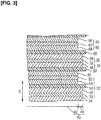
- Figure 3 is a sectional view illustrating the battery body and the power generation elements shown in Fig. 2 .
- the battery body 20 has negative electrodes 30, separators 50, and positive electrodes 60.
- the negative electrodes 30 have a negative electrode collector 32 and substantially rectangular negative electrode active material layers 34.
- the negative electrode active material layers 34 are disposed on both surfaces of the negative electrode collector 32 in the stacking direction S. In other words, the negative electrode collector 32 is shared by adjacent negative electrodes 30.
- the negative electrode collector 32 is constituted from a copper foil having a thickness of, e.g., about 1-100 ⁇ m.
- the negative electrode active material layers 34 contain a negative electrode active material and additives, and have a thickness of, e.g., about 1-100 ⁇ m.
- the negative electrode active material has a composition whereby lithium ions can be desorbed during discharging and lithium ions can be occluded during charging.
- the additives are a binder and an electroconductivity auxiliary.
- the binder is added for a purpose of maintaining the structure of the negative electrode, and has a function for binding together constituent materials of the negative electrode active material layers 34, and a function for causing the negative electrode active material layers 34 to bind to the negative electrode collector 32.
- the binder is constituted from carboxymethylcellulose (CMC) and styrene-butadiene rubber (SBR), for example.
- the electroconductivity auxiliary is constituted from a carbon material, etc., having good electrical conductivity, and is blended in order to enhance the electroconductivity of the negative electrode active material layers 34.
- the carbon material is acetylene
- the negative electrode active material includes a silicon-based material. Silicon has a better lithium ion occluding ability per unit volume than graphite, etc., which makes it possible to increase the capacity of a secondary battery.
- splitting of the negative electrode collector 32 caused by expansion and contraction of the negative electrode active material layer 34 is suppressed, as described hereinafter, and a negative electrode active material containing silicon, which has high expansibility, can therefore easily be applied.
- the positive electrodes 60 have a positive electrode collector 62 and a substantially rectangular positive electrode active material layer 64.
- a positive electrode active material layer 64 is disposed on both surfaces of the positive electrode collector 62 in the stacking direction S. In other words, the positive electrode collector 62 is shared by adjacent positive electrodes 60.
- the positive electrode collector 62 has a thickness of about 1-100 ⁇ m, for example.
- the material constituting the positive electrode collector 62 is the same as the material constituting the negative electrode collector 32.
- the positive electrode active material layers 64 contain a positive electrode active material and additives, and have a thickness of about 1-100 ⁇ m, for example.
- the positive electrode active material has a composition whereby lithium ions can be desorbed during charging and lithium ions can be occluded during discharging.
- the positive electrode active material is LiNiCoAlO 2 , for example.
- the additives are a binder and an electroconductivity auxiliary. The binder is added for a purpose of maintaining the structure of the positive electrode, and has a function for binding together constituent materials of the positive electrode active material layers 64, and a function for causing the positive electrode active material layers 64 to bind to the positive electrode collector 62.
- the binder is constituted from polyvinylidene fluoride (PVdF), for example.
- PVdF polyvinylidene fluoride
- the electroconductivity auxiliary is blended in order to enhance the electroconductivity of the positive electrode active material layers 64, and is the same as the electroconductivity auxiliary in the negative electrodes 30.
- the separators 50 are substantially rectangular porous material sheets (porous film) formed from polypropylene, and have a thickness of about 1-50 ⁇ m, for example.
- the separators 50 are disposed between the negative electrode active material layers 34 and the positive electrode active material layers 64, and the negative electrode active material layers 34 and the positive electrode active material layers 64 face each other, interposed by the separators 50.
- the separators 50 are impregnated with an electrolyte, and constitute electrolyte layers for retaining the electrolyte.
- the electrolyte is a liquid electrolyte, for example.
- the separators 50 have a function for ensuring conductivity of lithium ions (carrier ions) between the positive electrodes 60 and the negative electrodes 30, and function as barriers between the positive electrodes 60 and the negative electrodes 30.
- Each of the power generation elements 22 is constituted from a negative electrode collector 32, a negative electrode active material layer 34, a separator 50, a positive electrode active material layer 64, and a positive electrode collector 62.
- the negative electrode active material layer 34 is configured so as to have a larger area than the positive electrode active material layer 64. A decrease in a facing area between the negative electrode active material layer 34 and the positive electrode active material layer 64 is thereby suppressed even when the positive electrode active material layer 64 becomes misaligned with the negative electrode active material layer 34. Fluctuation in power generation capacity due to a decrease in the facing area is therefore prevented.
- the negative electrode collectors, the positive electrode collector, the silicon-based material of the negative electrode active material, the negative electrode binder, the positive electrode active material, the positive electrode binder, the electroconductivity auxiliary, the separators, and the composition of the electrolyte, etc., will next be described in this order.
- the material constituting the negative electrode collectors and the positive electrode collectors is not limited to copper; another metal or an electroconductive resin is applicable.
- the other metal is aluminum, nickel, iron, stainless steel, titanium, a cladding material of nickel and aluminum, a cladding material of copper aluminum, or a cladding material of a combination of these metals, for example.
- the electroconductive resin is an electroconductive polymer material, an electroconductive polymer material to which an electroconductive filler is added, or a non-electroconductive polymer material to which an electroconductive filler is added, for example.
- the silicon-based material of the negative electrode active material is silicon metal (elemental Si), a silicon alloy, a silicon oxide, a silicon compound, or a silicon semiconductor, for example.
- the silicon alloy includes aluminum, tin, zinc, nickel, copper, titanium, vanadium, magnesium, lithium, or another metal alloyed with silicon.
- the silicon alloy is preferably a Si-Sn-Ti-based alloy or another alloy based on three or more elements.
- the silicon oxide is SiO 2 , SiO, SiO x , etc.
- the SiO x is a mixture of amorphous SiO 2 particles and Si particles (where x represents a number of oxygen atoms satisfying a valence of Si).
- the silicon compound contains at least one component selected from the group consisting of lithium, carbon, aluminum, tin, zinc, nickel, copper, titanium, vanadium, and magnesium, for example.
- the negative electrode active material is not limited to a form including only one type of silicon-based material.
- the negative electrode binder is not limited to a form including styrene-butadiene rubber (SBR) and carboxymethylcellulose (CMC).
- SBR styrene-butadiene rubber
- CMC carboxymethylcellulose
- a rubber-based binder other than styrene-butadiene rubber (SBR) or a water-soluble polymer other than carboxymethylcellulose (CMC) is also applicable as the negative electrode binder.
- the negative electrode binder may be a single material, or three or more materials may be used jointly as needed.
- the positive electrode active material is not limited to a form including LiNiCoAlO 2 , and LiMn 2 O 4 , LiNiO 2 , LiCoO 2 , LiNiMnCoO 2 , LiFePO 4 , etc., for example, are also applicable as appropriate.
- the positive electrode binder is not limited to being constituted from polyvinylidene fluoride (PVdF).
- the electroconductivity auxiliary is not limited to being constituted from acetylene black.
- a carbon powder other than acetylene black, vapor-grown carbon fibers (VGCF®) and other carbon fibers, expanded graphite, etc. are also applicable.
- the porous material sheet constituting the separators is not limited to being formed from polypropylene.
- the porous material sheet can also be formed from polyethylene or another polyolefin other than polypropylene, a layered body in which a plurality of polyolefins are layered, polyimides, aramids, polyvinylidene fluoride-hexafluoropropylene (PVdF-HFP), glass fibers, etc.
- the separators can also be constituted from nonwoven fabric sheets.
- the nonwoven fabric sheets are formed from cotton, rayon, acetate, Nylon®, polyester, a polyolefin such as polyethylene or polypropylene, polyimides, aramids, etc., for example.
- the liquid electrolyte retained by the separators has a solvent and a lithium salt as a supporting electrolyte dissolved in the solvent.
- the lithium salt is Li(CF 3 SO 2 ) 2 N, Li(C 2 F 5 SO 2 ) 2 N, LiPF 6 , LiBF 4 , LiAsF 6 , LiTaF 6 , LiClO 4 , or LiCF 3 SO 3 .
- the solvent is ethylene carbonate (EC), propylene carbonate (PC), butylene carbonate (BC), vinylene carbonate (VC), dimethyl carbonate (DMC), diethyl carbonate (DEC), ethyl methyl carbonate (EMC), or methyl propyl carbonate (MPC), for example.
- the electrolyte retained by the separators is not limited to a liquid electrolyte.
- the separators can also retain a gel polymer electrolyte.
- the gel polymer electrolyte is constituted from a matrix polymer (host polymer) infused with a liquid electrolyte.
- the matrix polymer is an ion-conductive polymer. Examples of the ion-conductive polymer include polyethylene oxide (PEO), polypropylene oxide (PPO), and copolymers thereof.
- Figures 4 and 5 are plan views illustrating a negative electrode and a positive electrode shown in Fig. 3 .
- the negative electrode collector 32 of the negative electrode 30 has an active material region 40 and a non-active-material region 46.
- the active material region 40 is a region in which the negative electrode active material layer 34 is disposed on a surface, and has a facing section 42 and a non-facing section 44.
- the facing section 42 is a region facing the positive electrode active material layer 64, interposed by the separator 50, and the non-facing section 44 is a region not facing the positive electrode active material layer 64, the non-facing section 44 being positioned on a periphery (so as to surround the facing section 42) of the facing section 42 (see Fig. 3 ).
- the non-active-material region 46 protrudes from one side 41 of the substantially rectangular active material region 40, and is joined (fixed) to the negative electrode tab 12 for drawing electric current toward the outside.
- the positive electrode collector 62 of the positive electrode 60 has an active material region 70 and a non-active-material region 76.
- the active material region 70 is a region in which the positive electrode active material layer 64 is disposed on a surface, and is a facing section 72 facing the negative electrode active material layer 34, interposed by the separator 50.
- the non-active-material region 76 protrudes from one side 71 of the substantially rectangular active material region 70, and is joined (fixed) to the positive electrode tab 14 for drawing electric current toward the outside.
- the non-active-material region 76 is positioned so as not to overlap the non-active-material region 46 of the negative electrode collector 32 in the stacking direction S.
- Ultrasonic welding or resistance welding for example, is applied to join the negative electrode tab 12 and the non-active-material region 46 of the negative electrode 30 and to join the positive electrode tab 14 and the non-active-material region 76 of the positive electrode 60.
- Figure 6 is a sectional view illustrating the restraints for restraining the battery body.
- the restraints 80 are substantially U-shaped in cross section, and have a first contact section 81, a second contact section 88, and a connecting section 89, and are used for restraining the battery body 20 in the stacking direction S.
- the secondary battery 10 has four restraints 80 disposed along a periphery of the battery body 20. The number of restraints 80 and the positions in which the restraints 80 are disposed are not limited to the above configuration.
- the first contact sections 81 and the second contact sections 88 are used to apply a restraining force to one and another outermost layer of the battery body 20 in the stacking direction S.
- the restraining force is based on an adhesion force generated by adhesive material layers 92.
- negative electrode collectors 32 are positioned in one and the other outermost layer of the battery body 20. Consequently, the first contact sections 81 and the second contact sections 88 apply restraining force to the negative electrode collectors 32 positioned in one and the other outermost layer of the battery body 20.
- the one and the other outermost layers of the battery body 20 may also be negative electrode active material layers 34 disposed on a surface of a negative electrode collector 32, but the example described below is of a case in which one and the other outermost layer of the battery body 20 are negative electrode collectors 32.
- the connecting sections 89 extend alongside the battery body 20 in the stacking direction S and connect the first contact sections 81 and the second contact sections 88.
- the restraints 80 are formed from a pressure-sensitive-adhesive film having a base material layer 90 and an adhesive material layer 92 supported by the base material layer 90.
- the pressure-sensitive-adhesive film is Kapton® tape, for example.
- the base material layer 90 is constituted from a polyimide film, etc..
- the adhesive material layer 92 is constituted from a silicon-based adhesive material, an acrylic-based adhesive material, etc..
- the pressure-sensitive-adhesive film constituting the connecting section 89 does not have the adhesive material layer 92, but can also be constituted so as to have the adhesive material layer 92, as needed.
- the first contact sections 81 will next be described in detail.
- the second contact sections 88 have the same structure as the first contact sections 81 and will therefore not be described below, in order to avoid redundant description.
- Figure 7 is a plan view illustrating the first contact sections shown in Fig. 6
- Fig. 8 is a plan view illustrating a negative electrode collector to which restraining force is applied by the first contact sections
- Fig. 9 is an enlarged view illustrating slits shown in Fig. 7 .
- the first contact sections 81 shown in Fig. 7 are configured so that a stress occurring at boundaries B 1 of contact regions 33A and a non-contact region 33B shown in Fig. 8 is less than a breaking strength of the negative electrode collector 32.
- the contact regions 33A are regions in which the first contact sections 81 are in contact with a surface of the outermost layer (negative electrode collector 32 in the present example) of the battery body 20.
- the non-contact region 33B is a region in which the first contact sections 81 are not in contact.
- the stress is based on the restraining force of the first contact sections 81 and expansion and contraction of the negative electrode 30 due to a change in volume of the negative electrode active material layers caused by charging and discharging.
- the first contact sections 81 are substantially rectangular, and each have an end face 82, a base section 83, end face 82, side faces 84, 85, and slits 86.
- the base section 83 is linked to the connecting section 89 extending alongside the battery body 20.
- the end face 82 is a distal end located on an opposite side from the base section 83 and is positioned so as to face the facing section 42.
- the side faces 84, 85 link the end face 82 and the base section 83.
- the slits 86 extend toward the base section 83 from the end face 82, and reach at least to a position facing a boundary B 2 of the facing section 42 and the non-facing section 44.
- the slits 86 expand and contract along the end face 82 (in an extension direction of the end face 82), and the stress occurring at the boundaries (periphery of the contact regions 33A) B 1 is thereby dispersed (relieved).
- the first contact sections 81 are configured so as to expand and contract in accordance with the expansion and contraction of the negative electrode 30, and the stress occurring at the boundaries (periphery of the contact regions 33A) B 1 is thereby made less than the breaking strength of the negative electrode collector 32.
- a method of forming the slits 86 is not particularly limited, and a cutter can be used, for example.
- Figure 10 is a plan view illustrating the first modification of an embodiment of the present invention.
- the restraints 80 can also have a first contact section 81A shown in Fig. 10 .
- the first contact section 81A furthermore has slits 87A extending toward the side face 85 from the side face 84, and slits 87B extending toward the side face 84 from the side face 85.
- the slits 87A, 87B expand and contract along the side faces 84, 85 (in an extension direction of the side faces 84, 85), and the stress occurring at the boundaries (periphery of the contact regions 33A) B 1 is thereby dispersed (relieved).
- Figure 11 is a plan view illustrating the second modification of an embodiment of the present invention.
- the restraints 80 can also have a first contact section 81B shown in Fig. 11 .
- the first contact section 81B does not have the slits 86 extending toward the base section 83 from the end face 82, and has slits 87A extending toward the side face 85 from the side face 84, and slits 87B extending toward the side face 84 from the side face 85.
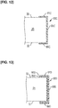
- Figure 12 is a sectional view illustrating the third modification of an embodiment of the present invention.
- the secondary battery 10 can also have a restraint 80C shown in Fig. 12 .
- the restraint 80C is constituted from an adhesive material having elasticity which enables the adhesive material to follow expansion and contraction of the negative electrode 30, and a first contact section 81C, a second contact section 88C, and a connecting section 89C are integrated in the restraint 80C.
- a restraining force of the first contact section 81C is based on an adhesive force generated by the adhesive material.
- the adhesive material is styrene-butadiene rubber (SBR), polyvinylidene fluoride (PVdF), a polyimide, polyacrylic acid, or another adhesive rubber material.
- stress occurring at the boundaries (periphery of the contact regions 33A) B 1 is dispersed (relieved) by expansion and contraction of the first contact sections 81C as such.
- an elasticity (Young's modulus) of the adhesive material is adjusted in advance so that the stress occurring at the boundaries B1 by expansion and contraction of the negative electrode 30 in an actual usage environment of the secondary battery 10 is less than the breaking strength of the negative electrode collector 32.
- the restraint 80C can be formed by applying a liquid adhesive material to a predetermined region and then drying the adhesive material.
- Figure 13 is a sectional view illustrating the fourth modification of an embodiment of the present invention.
- the secondary battery 10 can also have a restraint 80D shown in Fig. 13 .
- the restraint 80D is formed from a pressure-sensitive-adhesive film having a base material layer 90D and an adhesive material layer 92D supported by the base material layer 90D, and a first contact section 81D, a second contact section 88D, and a connecting section 89D are integrated in the restraint 80D.
- a restraining force of the first contact section 81D is based on an adhesive force generated by the adhesive material layer 92D.
- the adhesive material layer 92D is constituted from an adhesive material having elasticity which enables the adhesive material to follow expansion and contraction of the negative electrode 30, the same as in the third modification.
- the first contact section 81D corresponds to a configuration in which the base material layer 90D is combined with the first contact section 81C, and stress occurring at the boundaries (periphery of the contact regions 33A) B 1 is dispersed (relieved) by expansion and contraction of the adhesive material layer 92D as such.
- Figure 14 and Fig. 15 are a sectional view and a plan view, respectively, illustrating the fifth modification of an embodiment of the present invention.
- the secondary battery 10 can also have a restraint 80E shown in Fig. 14 .
- the restraint 80E is formed from a pressure-sensitive-adhesive film having a base material layer 90 and adhesive material layers 92E, and a first contact section 81E, a second contact section 88E, and a connecting section 89 are integrated in the restraint 80E.
- the adhesive material layers 92E are constituted from adhesive materials 93 disposed intermittently on the base material layer 90.
- a restraining force of the first contact section 81E is based on an adhesive force generated by the adhesive materials 93 (adhesive material layers 92E).
- the adhesive force generated by the adhesive material layers 92E is set so as to be less than the breaking strength of the negative electrode collector 32 by adjusting a configuration in which the adhesive materials 93 are arranged. Consequently, the first contact section 81E disperses (relieves) stress occurring at the boundaries (periphery of the contact regions 33A) B 1 . In other words, the stress can be made less than the breaking strength of the negative electrode collector 32.
- the configuration whereby the adhesive force generated by the adhesive material layers 92E is set is not particularly limited to the above configuration.
- Figure 16 is a sectional view illustrating the sixth modification of an embodiment of the present invention
- Fig. 17 is a sectional view illustrating the battery body and the power generation elements shown in Fig. 16
- Fig. 18 is a sectional view illustrating the restraints for restraining the battery body.
- the restraints 80 can also be applied to a secondary battery 10F and a battery body 20F shown in Fig. 16 .
- members having the same function as members of the secondary battery 10 will not be described below.
- the secondary battery 10F is a bipolar lithium-ion secondary battery, and has a negative electrode tab 12F, a positive electrode tab 14F, and an exterior body 16.
- a battery body 20F, restraints 80 (see Fig. 18 ), and a seal (not illustrated) are disposed in the exterior body 16.
- the negative electrode tab 12F and the positive electrode tab 14F are disposed outside the battery body 20F, and are configured so as to at least cover an entire electrode projection surface.
- the battery body 20F has negative electrode active material layers 34, separators 50, positive electrode active material layers 64, and collectors 96.
- the negative electrode active material layers 34 include a silicon-based material, and are disposed on one surface of the collectors 96.
- the positive electrode active material layers 64 are disposed on another surface of the collectors 96.
- a negative electrode active material layer 34 and a collectors 96 constitute a negative electrode 30F, and a positive electrode active material layer 64 and a collector 96 constitute a positive electrode 60F.
- the collector 96 is a bipolar collectors shared by the negative electrode 30F and the positive electrode 60F (serving as a negative electrode collector and a positive electrode collector).
- the separators 50 are disposed between the negative electrode active material layers 34 and the positive electrode active material layers 64. Consequently, a collector 96, a negative electrode active material layer 34, a separator 50, a positive electrode active material layer 64, and a collector 96 constitute a power generation element (single unit battery) 22F. Power generation elements 22F are stacked and electrically connected in series.
- the negative electrode active material layers 34 are configured so as to have a larger area than the positive electrode active material layers 64. Consequently, an active material region 40 of the collectors 96 in which the negative electrode active material layers 34 are disposed has a facing section 42 in which the electrode active material layers 64 are faced, interposed by the separators 50, and a non-facing section 44 in which the positive electrode active material layers 64 are not faced, the non-facing section 44 being positioned on the periphery (so as to surround the facing section 42) of the facing section 42 (see Fig. 17 ).
- the seal is disposed so as to surround a periphery of the positive electrode active material layers 64 and the negative electrode active material layers 34, and is provided to seal at least a portion of an outer circumferential section of the power generation elements 22.
- the seal can also be omitted, as appropriate, in accordance with a configuration of the electrolyte (electrolytic solution).
- the restraints 80 are substantially U-shaped in cross section, and have a first contact section 81, a second contact section 88, and a connecting section 89, and are used for restraining the battery body 20F in the stacking direction S.
- the first contact sections 81 and the second contact sections 88 apply a restraining force to the collectors 96 positioned on one and another outermost layer of the battery body 20F.
- a collector 96 for functioning as a negative electrode collector and a collector 96 for functioning as a positive electrode collector are positioned in one and the other outermost layer of the battery body 20F. Consequently, the first contact sections 81 are in contact with a collector 96 for functioning as a negative electrode collector.
- the first contact sections 81 are therefore configured so that a stress occurring at boundaries B 1 (see Fig. 8 ) of contact regions 33A and a non-contact region 33B is less than a breaking strength of the collectors 96.
- the stress occurring at the boundaries (periphery of the contact regions 33A) B 1 is made less than the breaking strength of the collectors 96. Consequently, it is possible to suppress splitting of the collectors 96 at the boundaries (periphery of the contact regions 33A) B 1 , caused by expansion and contraction of the silicon-containing negative electrode active material layers.
- the collector 96 positioned in an uppermost layer does not have a positive electrode active material layer 64, and the collector 96 positioned in a lowermost layer does not have a negative electrode active material layer 34.
- the reason for this is that a positive electrode active material layer 64 and a negative electrode active material layer 34 positioned on outsides of collectors 96 positioned in the uppermost layer and the lowermost layer do not participate in a battery reaction.
- the battery can also be configured so as to have a bipolar electrode structure.
- a configuration is adopted whereby stress occurring at the boundaries of the non-contact region and the contact regions of the first contact sections is less than the breaking strength of the negative electrode collectors, and the stress is relieved. Splitting of the negative electrode collectors at the boundaries (periphery of the contact regions) of the contact regions and the non-contact region is therefore suppressed.
- a secondary battery can be provided in which it is possible to suppress splitting of the negative electrode collectors caused by contraction and expansion of the silicon-containing negative electrode active material layers.
- first contact sections are configured so as to expand and contract in accordance with contraction and expansion of the negative electrodes
- stress occurring at the boundaries of the non-contact region and the contact regions of the first contact sections can be relieved by the expansion and contraction of the first contact sections.
- the stress can be made less than the breaking strength of the negative electrode collectors.
- slits which extend toward the base section from the end face and reach at least to a position facing the boundary of the facing section and the non-facing section
- stress occurring at the boundaries of the non-contact region and the contact regions of the first contact sections, positioned at end faces of the first contact sections can be dispersed (relieved) by expansion and contraction of the slits along the end faces (in the extension direction of the end faces) of the first contact sections.
- slits which extend from a side face toward another side face, stress occurring at the boundaries of the non-contact region and the contact regions of the first contact sections, positioned at end faces of the first contact sections, can be dispersed (relieved) by expansion and contraction of the slits along the side faces (in the extension direction of the side faces) of the first contact sections.
- first contact sections are formed from an adhesive material having elasticity which enables the adhesive material to follow expansion and contraction of the negative electrodes
- stress occurring at the boundaries of the non-contact region and the contact regions of the first contact sections, positioned at end faces of the first contact sections can be dispersed (relieved) by expansion and contraction of the first contact sections as such.
- the restraints are formed entirely from the adhesive material, the structure of the restraints can be simplified.
- the first contact sections have an adhesive material layer formed from an adhesive material having elasticity which enables the adhesive material to follow expansion and contraction of the negative electrodes, and a base material layer for supporting the adhesive material layer, the adhesive material (adhesive material layer) is easily handled.
- the first contact sections have an adhesive material layer and a base material layer for supporting the adhesive material layer, and the adhesive force generated by the adhesive material layer is set so as to be less than the breaking strength of the negative electrode collectors, stress occurring at the boundaries of the non-contact region and the contact regions of the first contact sections can be relieved and made less than the breaking strength of the negative electrode collectors.
- the adhesive material constituting the adhesive material layer is disposed intermittently on the base material layer, the adhesive force generated by the adhesive material layer can easily be set.
- the structure of the restraints can be simplified.
- the secondary battery can also be used in the form of a serialized and/or parallelized assembled battery.
- the method for configuring the first contact sections so as to expand and contract in accordance with expansion and contraction of the negative electrodes is not limited to providing slits or using an adhesive material having elasticity which enables the adhesive material to follow expansion and contraction of the negative electrodes.
- the first to fifth modifications can also be applied and used in the sixth modification.
Landscapes
- Chemical & Material Sciences (AREA)
- Chemical Kinetics & Catalysis (AREA)
- Electrochemistry (AREA)
- General Chemical & Material Sciences (AREA)
- Engineering & Computer Science (AREA)
- Manufacturing & Machinery (AREA)
- Materials Engineering (AREA)
- Secondary Cells (AREA)
- Battery Electrode And Active Subsutance (AREA)
- Inorganic Chemistry (AREA)
Abstract
Description
- The present invention relates to a secondary battery.
- A secondary battery has a battery body and a restraint. The battery body has a plurality of stacked power generation elements. The power generation elements have a positive electrode having a positive electrode collector in which a positive electrode active material layer is disposed on a surface thereof, an electrolyte layer for retaining an electrolyte, and a negative electrode having a negative electrode collector in which a negative electrode active material layer is disposed on a surface thereof. The positive electrode active material layer and the negative electrode active material layer face each other, interposed by the electrolyte layer.
- The restraint is constituted from a pressure-sensitive-adhesive tape provided in order to prevent misalignment of constituent materials of the battery body (see Patent Document 1, for example). The pressure-sensitive-adhesive tape extends from one outermost layer of the battery body, the layer being outermost in a stacking direction of the power generation elements, to another outermost layer of the battery body via a side of the battery body, and applies a restraining force to the one outermost layer and the other outermost layer of the battery body.
- Patent Document 1: International Publication No.
WO 2014/188607 - A negative electrode active material containing silicon has been applied in a negative electrode active material layer in recent years for the purpose of increasing battery capacity.
- However, silicon characteristically undergoes a large change in volume in response to charging and discharging of the secondary battery, and significantly expands and contracts in a direction of a plane intersecting with the stacking direction of the power generation elements. Problems therefore arise in the negative electrode collector positioned in at least one outermost layer of the battery body.
- For example, in a contact region of the negative electrode collector, in which the pressure-sensitive-adhesive tape is in contact with the negative electrode collector, expansion and contraction is restricted, and there is therefore a marked difference between the contact region and a non-contact region with regard to an amount of expansion and contraction. Splitting of the negative electrode collector can therefore occur at a boundary (periphery of the contact region) of the contact region and the non-contact region.
- Localized splitting of the negative electrode collector reduces battery output and/or battery capacity, and the localized splitting grows as a result of repeated charging and discharging of the secondary battery and can cause cycle characteristics (service life) to deteriorate.
- The present invention was contrived in order to overcome the problems of the prior art described above, and an object of the present invention is to provide a secondary battery in which it is possible to suppress splitting of a negative electrode collector caused by contraction and expansion of a silicon-containing negative electrode active material layer.
- The present invention for achieving the abovementioned object is a secondary battery comprising a battery body having a plurality of stacked power generation elements, and a restraint for restraining the battery body in a stacking direction of the power generation elements, a first contact section of the restraint for applying a restraining force to a surface of one outermost layer of the battery body being configured so that a stress occurring at a boundary of a non-contact region and a contact region of the first contact section is less than a breaking strength of the negative electrode collector, the stress being based on the restraining force and expansion and contraction of a negative electrode due to a change in volume of a negative electrode active material layer caused by charging and discharging.
- The present invention is configured so that the stress occurring at the boundary of the non-contact region and the contact region of the first contact section is less than the breaking strength of the negative electrode collector, and the stress is relieved. Splitting of the negative electrode collector at the boundary (periphery of the contact region) of the contact region and the non-contact region is therefore suppressed. In other words, a secondary battery can be provided in which it is possible to suppress splitting of the negative electrode collector caused by contraction and expansion of the silicon-containing negative electrode active material layer.
- Other objects, features, and characteristics of the present invention will become apparent from the preferred embodiments presented as examples in the following description and the accompanying drawings.
-
-
Figure 1 is an oblique view illustrating a secondary battery according to an embodiment of the present invention; -
Figure 2 is a sectional view of the secondary battery shown inFig. 1 ; -
Figure 3 is a sectional view illustrating a battery body and power generation elements shown inFig. 2 ; -
Figure 4 is a plan view illustrating a negative electrode shown inFig. 3 ; -
Figure 5 is a plan view illustrating a positive electrode shown inFig. 3 ; -
Figure 6 is a sectional view illustrating restraints for restraining the battery body; -
Figure 7 is a plan view illustrating first contact sections shown inFig. 6 ; -
Figure 8 is a plan view illustrating a negative electrode collector to which a restraining force is applied by the first contact sections; -
Figure 9 is an enlarged view illustrating slits shown inFig. 7 ; -
Figure 10 is a plan view illustrating the first modification of an embodiment of the present invention; -
Figure 11 is a plan view illustrating the second modification of an embodiment of the present invention; -
Figure 12 is a sectional view illustrating the third modification of an embodiment of the present invention; -
Figure 13 is a sectional view illustrating the fourth modification of an embodiment of the present invention; -
Figure 14 is a sectional view illustrating the fifth modification of an embodiment of the present invention; -
Figure 15 is a plan view illustrating the fifth modification of an embodiment of the present invention; -
Figure 16 is a sectional view illustrating the sixth modification of an embodiment of the present invention; -
Figure 17 is a sectional view illustrating the battery body and the power generation elements shown inFig. 16 ; -
Figure 18 is a sectional view illustrating the restraints for restraining the battery body. - Embodiments of the present invention are described below with reference to the accompanying drawings. Ratios of dimensions in the drawings are sometimes exaggerated for convenience of description, and may vary from actual ratios.
-
Figure 1 is an oblique view illustrating a secondary battery according to an embodiment of the present invention, andFig. 2 is a sectional view of the secondary battery shown inFig. 1 . - A
secondary battery 10 according to an embodiment of the present invention is a non-bipolar lithium-ion secondary battery, and has anegative electrode tab 12, apositive electrode tab 14, and anexterior body 16, as indicated inFig. 1 . Thesecondary battery 10 is configured as a battery assembly and used as a power source device for a vehicle, for example. The vehicle is an electric automobile or a hybrid electric automobile, for example. - The
negative electrode tab 12 and thepositive electrode tab 14 are electrode terminals comprising highly electroconductive members. The tabs extend out from inside theexterior body 16, and are used for sending out electric current. Thenegative electrode tab 12 and thepositive electrode tab 14 are preferably covered by, for example, a heat-resistant and insulating heat-shrinkable tubing, and are thereby reliably prevented from coming in electrical contact with peripheral equipment, wiring, etc. - As indicated in
Fig. 2 , abattery body 20 and restraints 80 (not illustrated) are disposed inside theexterior body 16, and theexterior body 16 is used to prevent shock of external origin or environmental degradation. Theexterior body 16 is formed by joining all or a portion of an external peripheral part of a sheet member. Examples of the joining method include thermal fusion bonding. - The
battery body 20 has a plurality of power generation elements (unit batteries) 22. Thepower generation elements 22 are stacked and electrically connected in parallel. The restraints 80 (not illustrated) are used for restraining thebattery body 20 in a stacking direction S of thepower generation elements 22, as described hereinafter. - The highly electroconductive members constituting the
negative electrode tab 12 and thepositive electrode tab 14 are aluminum, copper, titanium, nickel, stainless steel, or an alloy thereof, for example. - The sheet member constituting the
exterior body 16 is preferably constituted from a polymer-metal composite laminate film, for the sake of weight reduction and thermal conductivity. The polymer is polypropylene, polyethylene, or another thermoplastic resin material, for example. The metal is, for example, aluminum, stainless steel, nickel, copper, etc. (including alloys of these). Theexterior body 16 is not limited to being constituted from a pair of laminate films (sheet members); for example, a laminate film formed in a bag shape in advance can be used as well. - The battery body and the power generation elements will next be described in detail.
-
Figure 3 is a sectional view illustrating the battery body and the power generation elements shown inFig. 2 . - As indicated in
Fig. 3 , thebattery body 20 hasnegative electrodes 30,separators 50, andpositive electrodes 60. - The
negative electrodes 30 have anegative electrode collector 32 and substantially rectangular negative electrode active material layers 34. The negative electrode active material layers 34 are disposed on both surfaces of thenegative electrode collector 32 in the stacking direction S. In other words, thenegative electrode collector 32 is shared by adjacentnegative electrodes 30. Thenegative electrode collector 32 is constituted from a copper foil having a thickness of, e.g., about 1-100 µm. - The negative electrode active material layers 34 contain a negative electrode active material and additives, and have a thickness of, e.g., about 1-100 µm. The negative electrode active material has a composition whereby lithium ions can be desorbed during discharging and lithium ions can be occluded during charging. The additives are a binder and an electroconductivity auxiliary. The binder is added for a purpose of maintaining the structure of the negative electrode, and has a function for binding together constituent materials of the negative electrode active material layers 34, and a function for causing the negative electrode active material layers 34 to bind to the
negative electrode collector 32. The binder is constituted from carboxymethylcellulose (CMC) and styrene-butadiene rubber (SBR), for example. The electroconductivity auxiliary is constituted from a carbon material, etc., having good electrical conductivity, and is blended in order to enhance the electroconductivity of the negative electrode active material layers 34. The carbon material is acetylene black, for example. - In the present embodiment, the negative electrode active material includes a silicon-based material. Silicon has a better lithium ion occluding ability per unit volume than graphite, etc., which makes it possible to increase the capacity of a secondary battery. In particular, in the present embodiment, splitting of the
negative electrode collector 32 caused by expansion and contraction of the negative electrodeactive material layer 34 is suppressed, as described hereinafter, and a negative electrode active material containing silicon, which has high expansibility, can therefore easily be applied. - The
positive electrodes 60 have apositive electrode collector 62 and a substantially rectangular positive electrodeactive material layer 64. A positive electrodeactive material layer 64 is disposed on both surfaces of thepositive electrode collector 62 in the stacking direction S. In other words, thepositive electrode collector 62 is shared by adjacentpositive electrodes 60. - The
positive electrode collector 62 has a thickness of about 1-100 µm, for example. The material constituting thepositive electrode collector 62 is the same as the material constituting thenegative electrode collector 32. - The positive electrode active material layers 64 contain a positive electrode active material and additives, and have a thickness of about 1-100 µm, for example. The positive electrode active material has a composition whereby lithium ions can be desorbed during charging and lithium ions can be occluded during discharging. The positive electrode active material is LiNiCoAlO2, for example. The additives are a binder and an electroconductivity auxiliary. The binder is added for a purpose of maintaining the structure of the positive electrode, and has a function for binding together constituent materials of the positive electrode active material layers 64, and a function for causing the positive electrode active material layers 64 to bind to the
positive electrode collector 62. The binder is constituted from polyvinylidene fluoride (PVdF), for example. The electroconductivity auxiliary is blended in order to enhance the electroconductivity of the positive electrode active material layers 64, and is the same as the electroconductivity auxiliary in thenegative electrodes 30. - The
separators 50 are substantially rectangular porous material sheets (porous film) formed from polypropylene, and have a thickness of about 1-50 µm, for example. Theseparators 50 are disposed between the negative electrode active material layers 34 and the positive electrode active material layers 64, and the negative electrode active material layers 34 and the positive electrode active material layers 64 face each other, interposed by theseparators 50. - The
separators 50 are impregnated with an electrolyte, and constitute electrolyte layers for retaining the electrolyte. The electrolyte is a liquid electrolyte, for example. In other words, theseparators 50 have a function for ensuring conductivity of lithium ions (carrier ions) between thepositive electrodes 60 and thenegative electrodes 30, and function as barriers between thepositive electrodes 60 and thenegative electrodes 30. - Each of the
power generation elements 22 is constituted from anegative electrode collector 32, a negative electrodeactive material layer 34, aseparator 50, a positive electrodeactive material layer 64, and apositive electrode collector 62. - The negative electrode
active material layer 34 is configured so as to have a larger area than the positive electrodeactive material layer 64. A decrease in a facing area between the negative electrodeactive material layer 34 and the positive electrodeactive material layer 64 is thereby suppressed even when the positive electrodeactive material layer 64 becomes misaligned with the negative electrodeactive material layer 34. Fluctuation in power generation capacity due to a decrease in the facing area is therefore prevented. - The negative electrode collectors, the positive electrode collector, the silicon-based material of the negative electrode active material, the negative electrode binder, the positive electrode active material, the positive electrode binder, the electroconductivity auxiliary, the separators, and the composition of the electrolyte, etc., will next be described in this order.
- The material constituting the negative electrode collectors and the positive electrode collectors is not limited to copper; another metal or an electroconductive resin is applicable. The other metal is aluminum, nickel, iron, stainless steel, titanium, a cladding material of nickel and aluminum, a cladding material of copper aluminum, or a cladding material of a combination of these metals, for example. The electroconductive resin is an electroconductive polymer material, an electroconductive polymer material to which an electroconductive filler is added, or a non-electroconductive polymer material to which an electroconductive filler is added, for example.
- The silicon-based material of the negative electrode active material is silicon metal (elemental Si), a silicon alloy, a silicon oxide, a silicon compound, or a silicon semiconductor, for example. The silicon alloy includes aluminum, tin, zinc, nickel, copper, titanium, vanadium, magnesium, lithium, or another metal alloyed with silicon. The silicon alloy is preferably a Si-Sn-Ti-based alloy or another alloy based on three or more elements. The silicon oxide is SiO2, SiO, SiOx, etc. The SiOx is a mixture of amorphous SiO2 particles and Si particles (where x represents a number of oxygen atoms satisfying a valence of Si). The silicon compound contains at least one component selected from the group consisting of lithium, carbon, aluminum, tin, zinc, nickel, copper, titanium, vanadium, and magnesium, for example. The negative electrode active material is not limited to a form including only one type of silicon-based material.
- The negative electrode binder is not limited to a form including styrene-butadiene rubber (SBR) and carboxymethylcellulose (CMC). For example, a rubber-based binder other than styrene-butadiene rubber (SBR) or a water-soluble polymer other than carboxymethylcellulose (CMC) is also applicable as the negative electrode binder. The negative electrode binder may be a single material, or three or more materials may be used jointly as needed.
- The positive electrode active material is not limited to a form including LiNiCoAlO2, and LiMn2O4, LiNiO2, LiCoO2, LiNiMnCoO2, LiFePO4, etc., for example, are also applicable as appropriate.
- The positive electrode binder is not limited to being constituted from polyvinylidene fluoride (PVdF).
- The electroconductivity auxiliary is not limited to being constituted from acetylene black. For example, a carbon powder other than acetylene black, vapor-grown carbon fibers (VGCF®) and other carbon fibers, expanded graphite, etc. are also applicable.
- The porous material sheet constituting the separators is not limited to being formed from polypropylene. For example, the porous material sheet can also be formed from polyethylene or another polyolefin other than polypropylene, a layered body in which a plurality of polyolefins are layered, polyimides, aramids, polyvinylidene fluoride-hexafluoropropylene (PVdF-HFP), glass fibers, etc. The separators can also be constituted from nonwoven fabric sheets. The nonwoven fabric sheets are formed from cotton, rayon, acetate, Nylon®, polyester, a polyolefin such as polyethylene or polypropylene, polyimides, aramids, etc., for example.
- The liquid electrolyte retained by the separators has a solvent and a lithium salt as a supporting electrolyte dissolved in the solvent. Examples of the lithium salt is Li(CF3SO2)2N, Li(C2F5SO2)2N, LiPF6, LiBF4, LiAsF6, LiTaF6, LiClO4, or LiCF3SO3. The solvent is ethylene carbonate (EC), propylene carbonate (PC), butylene carbonate (BC), vinylene carbonate (VC), dimethyl carbonate (DMC), diethyl carbonate (DEC), ethyl methyl carbonate (EMC), or methyl propyl carbonate (MPC), for example.
- The electrolyte retained by the separators is not limited to a liquid electrolyte. For example, the separators can also retain a gel polymer electrolyte. The gel polymer electrolyte is constituted from a matrix polymer (host polymer) infused with a liquid electrolyte. The matrix polymer is an ion-conductive polymer. Examples of the ion-conductive polymer include polyethylene oxide (PEO), polypropylene oxide (PPO), and copolymers thereof.
- A structure of the negative electrodes and the positive electrodes will next be described.
-
Figures 4 and 5 are plan views illustrating a negative electrode and a positive electrode shown inFig. 3 . - As indicated in
Fig. 4 , thenegative electrode collector 32 of thenegative electrode 30 has anactive material region 40 and a non-active-material region 46. Theactive material region 40 is a region in which the negative electrodeactive material layer 34 is disposed on a surface, and has a facingsection 42 and anon-facing section 44. - The facing
section 42 is a region facing the positive electrodeactive material layer 64, interposed by theseparator 50, and thenon-facing section 44 is a region not facing the positive electrodeactive material layer 64, thenon-facing section 44 being positioned on a periphery (so as to surround the facing section 42) of the facing section 42 (seeFig. 3 ). - The non-active-
material region 46 protrudes from oneside 41 of the substantially rectangularactive material region 40, and is joined (fixed) to thenegative electrode tab 12 for drawing electric current toward the outside. - As indicated in
Fig. 5 , thepositive electrode collector 62 of thepositive electrode 60 has anactive material region 70 and a non-active-material region 76. Theactive material region 70 is a region in which the positive electrodeactive material layer 64 is disposed on a surface, and is a facing section 72 facing the negative electrodeactive material layer 34, interposed by theseparator 50. - The non-active-
material region 76 protrudes from oneside 71 of the substantially rectangularactive material region 70, and is joined (fixed) to thepositive electrode tab 14 for drawing electric current toward the outside. - The non-active-
material region 76 is positioned so as not to overlap the non-active-material region 46 of thenegative electrode collector 32 in the stacking direction S. Ultrasonic welding or resistance welding, for example, is applied to join thenegative electrode tab 12 and the non-active-material region 46 of thenegative electrode 30 and to join thepositive electrode tab 14 and the non-active-material region 76 of thepositive electrode 60. - The restraints will next be described.
-
Figure 6 is a sectional view illustrating the restraints for restraining the battery body. - As indicated in
Fig. 6 , therestraints 80 are substantially U-shaped in cross section, and have afirst contact section 81, asecond contact section 88, and a connectingsection 89, and are used for restraining thebattery body 20 in the stacking direction S. In the present embodiment, thesecondary battery 10 has fourrestraints 80 disposed along a periphery of thebattery body 20. The number ofrestraints 80 and the positions in which therestraints 80 are disposed are not limited to the above configuration. - The
first contact sections 81 and thesecond contact sections 88 are used to apply a restraining force to one and another outermost layer of thebattery body 20 in the stacking direction S. The restraining force is based on an adhesion force generated by adhesive material layers 92. - In the present embodiment,
negative electrode collectors 32 are positioned in one and the other outermost layer of thebattery body 20. Consequently, thefirst contact sections 81 and thesecond contact sections 88 apply restraining force to thenegative electrode collectors 32 positioned in one and the other outermost layer of thebattery body 20. The one and the other outermost layers of thebattery body 20 may also be negative electrode active material layers 34 disposed on a surface of anegative electrode collector 32, but the example described below is of a case in which one and the other outermost layer of thebattery body 20 arenegative electrode collectors 32. - The connecting
sections 89 extend alongside thebattery body 20 in the stacking direction S and connect thefirst contact sections 81 and thesecond contact sections 88. - The
restraints 80 are formed from a pressure-sensitive-adhesive film having abase material layer 90 and anadhesive material layer 92 supported by thebase material layer 90. The pressure-sensitive-adhesive film is Kapton® tape, for example. Thebase material layer 90 is constituted from a polyimide film, etc.. Theadhesive material layer 92 is constituted from a silicon-based adhesive material, an acrylic-based adhesive material, etc.. The pressure-sensitive-adhesive film constituting the connectingsection 89 does not have theadhesive material layer 92, but can also be constituted so as to have theadhesive material layer 92, as needed. - The
first contact sections 81 will next be described in detail. Thesecond contact sections 88 have the same structure as thefirst contact sections 81 and will therefore not be described below, in order to avoid redundant description. -
Figure 7 is a plan view illustrating the first contact sections shown inFig. 6 ,Fig. 8 is a plan view illustrating a negative electrode collector to which restraining force is applied by the first contact sections, andFig. 9 is an enlarged view illustrating slits shown inFig. 7 . - The
first contact sections 81 shown inFig. 7 are configured so that a stress occurring at boundaries B1 ofcontact regions 33A and anon-contact region 33B shown inFig. 8 is less than a breaking strength of thenegative electrode collector 32. Thecontact regions 33A are regions in which thefirst contact sections 81 are in contact with a surface of the outermost layer (negative electrode collector 32 in the present example) of thebattery body 20. Thenon-contact region 33B is a region in which thefirst contact sections 81 are not in contact. The stress is based on the restraining force of thefirst contact sections 81 and expansion and contraction of thenegative electrode 30 due to a change in volume of the negative electrode active material layers caused by charging and discharging. - Specifically, as indicated in
Fig. 9 , thefirst contact sections 81 are substantially rectangular, and each have anend face 82, abase section 83,end face 82, side faces 84, 85, and slits 86. - The
base section 83 is linked to the connectingsection 89 extending alongside thebattery body 20. Theend face 82 is a distal end located on an opposite side from thebase section 83 and is positioned so as to face the facingsection 42. The side faces 84, 85 link theend face 82 and thebase section 83. - The
slits 86 extend toward thebase section 83 from theend face 82, and reach at least to a position facing a boundary B2 of the facingsection 42 and thenon-facing section 44. Theslits 86 expand and contract along the end face 82 (in an extension direction of the end face 82), and the stress occurring at the boundaries (periphery of thecontact regions 33A) B1 is thereby dispersed (relieved). - In other words, the
first contact sections 81 are configured so as to expand and contract in accordance with the expansion and contraction of thenegative electrode 30, and the stress occurring at the boundaries (periphery of thecontact regions 33A) B1 is thereby made less than the breaking strength of thenegative electrode collector 32. - Consequently, it is possible to suppress splitting of the
negative electrode collector 32 at the boundaries (periphery of thecontact regions 33A) B1, caused by expansion and contraction of the silicon-containing negative electrode active material layer. As a result, a decrease in battery output and/or battery capacity based on localized splitting of thenegative electrode collector 32 is suppressed, growth of localized splitting of thenegative electrode collector 32 due to repeated charging and discharging of the secondary battery is avoided, and deterioration of cycle characteristics (service life) is suppressed. - A method of forming the
slits 86 is not particularly limited, and a cutter can be used, for example. - First to sixth modifications will next be described in order.
-
Figure 10 is a plan view illustrating the first modification of an embodiment of the present invention. - The
restraints 80 can also have afirst contact section 81A shown inFig. 10 . In addition to theslits 86 extending toward thebase section 83 from the end faces 82, thefirst contact section 81A furthermore has slits 87A extending toward the side face 85 from theside face 84, and slits 87B extending toward the side face 84 from theside face 85. The slits 87A, 87B expand and contract along the side faces 84, 85 (in an extension direction of the side faces 84, 85), and the stress occurring at the boundaries (periphery of thecontact regions 33A) B1 is thereby dispersed (relieved). -
Figure 11 is a plan view illustrating the second modification of an embodiment of the present invention. - The
restraints 80 can also have afirst contact section 81B shown inFig. 11 . Thefirst contact section 81B does not have theslits 86 extending toward thebase section 83 from theend face 82, and has slits 87A extending toward the side face 85 from theside face 84, and slits 87B extending toward the side face 84 from theside face 85. -
Figure 12 is a sectional view illustrating the third modification of an embodiment of the present invention. - The
secondary battery 10 can also have arestraint 80C shown inFig. 12 . Therestraint 80C is constituted from an adhesive material having elasticity which enables the adhesive material to follow expansion and contraction of thenegative electrode 30, and afirst contact section 81C, asecond contact section 88C, and a connectingsection 89C are integrated in therestraint 80C. A restraining force of thefirst contact section 81C is based on an adhesive force generated by the adhesive material. The adhesive material is styrene-butadiene rubber (SBR), polyvinylidene fluoride (PVdF), a polyimide, polyacrylic acid, or another adhesive rubber material. - In this case, stress occurring at the boundaries (periphery of the
contact regions 33A) B1 is dispersed (relieved) by expansion and contraction of thefirst contact sections 81C as such. Specifically, an elasticity (Young's modulus) of the adhesive material is adjusted in advance so that the stress occurring at the boundaries B1 by expansion and contraction of thenegative electrode 30 in an actual usage environment of thesecondary battery 10 is less than the breaking strength of thenegative electrode collector 32. Therestraint 80C can be formed by applying a liquid adhesive material to a predetermined region and then drying the adhesive material. -
Figure 13 is a sectional view illustrating the fourth modification of an embodiment of the present invention. - The
secondary battery 10 can also have arestraint 80D shown inFig. 13 . Therestraint 80D is formed from a pressure-sensitive-adhesive film having abase material layer 90D and anadhesive material layer 92D supported by thebase material layer 90D, and afirst contact section 81D, asecond contact section 88D, and a connectingsection 89D are integrated in therestraint 80D. A restraining force of thefirst contact section 81D is based on an adhesive force generated by theadhesive material layer 92D. - The
adhesive material layer 92D is constituted from an adhesive material having elasticity which enables the adhesive material to follow expansion and contraction of thenegative electrode 30, the same as in the third modification. In other words, thefirst contact section 81D corresponds to a configuration in which thebase material layer 90D is combined with thefirst contact section 81C, and stress occurring at the boundaries (periphery of thecontact regions 33A) B1 is dispersed (relieved) by expansion and contraction of theadhesive material layer 92D as such. -
Figure 14 and Fig. 15 are a sectional view and a plan view, respectively, illustrating the fifth modification of an embodiment of the present invention. - The
secondary battery 10 can also have arestraint 80E shown inFig. 14 . Therestraint 80E is formed from a pressure-sensitive-adhesive film having abase material layer 90 and adhesive material layers 92E, and afirst contact section 81E, asecond contact section 88E, and a connectingsection 89 are integrated in therestraint 80E. As indicated inFig. 15 , theadhesive material layers 92E are constituted fromadhesive materials 93 disposed intermittently on thebase material layer 90. A restraining force of thefirst contact section 81E is based on an adhesive force generated by the adhesive materials 93 (adhesive material layers 92E). - The adhesive force generated by the
adhesive material layers 92E is set so as to be less than the breaking strength of thenegative electrode collector 32 by adjusting a configuration in which theadhesive materials 93 are arranged. Consequently, thefirst contact section 81E disperses (relieves) stress occurring at the boundaries (periphery of thecontact regions 33A) B1. In other words, the stress can be made less than the breaking strength of thenegative electrode collector 32. The configuration whereby the adhesive force generated by theadhesive material layers 92E is set is not particularly limited to the above configuration. -
Figure 16 is a sectional view illustrating the sixth modification of an embodiment of the present invention,Fig. 17 is a sectional view illustrating the battery body and the power generation elements shown inFig. 16 , andFig. 18 is a sectional view illustrating the restraints for restraining the battery body. - The
restraints 80 can also be applied to asecondary battery 10F and abattery body 20F shown inFig. 16 . In order to avoid redundant description, members having the same function as members of thesecondary battery 10 will not be described below. - Specifically, the
secondary battery 10F is a bipolar lithium-ion secondary battery, and has anegative electrode tab 12F, a positive electrode tab 14F, and anexterior body 16. Abattery body 20F, restraints 80 (seeFig. 18 ), and a seal (not illustrated) are disposed in theexterior body 16. Thenegative electrode tab 12F and the positive electrode tab 14F are disposed outside thebattery body 20F, and are configured so as to at least cover an entire electrode projection surface. - As indicated in
Fig. 17 , thebattery body 20F has negative electrode active material layers 34,separators 50, positive electrode active material layers 64, andcollectors 96. The negative electrode active material layers 34 include a silicon-based material, and are disposed on one surface of thecollectors 96. The positive electrode active material layers 64 are disposed on another surface of thecollectors 96. A negative electrodeactive material layer 34 and acollectors 96 constitute a negative electrode 30F, and a positive electrodeactive material layer 64 and acollector 96 constitute apositive electrode 60F. In other words, thecollector 96 is a bipolar collectors shared by the negative electrode 30F and thepositive electrode 60F (serving as a negative electrode collector and a positive electrode collector). - The
separators 50 are disposed between the negative electrode active material layers 34 and the positive electrode active material layers 64. Consequently, acollector 96, a negative electrodeactive material layer 34, aseparator 50, a positive electrodeactive material layer 64, and acollector 96 constitute a power generation element (single unit battery) 22F.Power generation elements 22F are stacked and electrically connected in series. - The negative electrode active material layers 34 are configured so as to have a larger area than the positive electrode active material layers 64. Consequently, an
active material region 40 of thecollectors 96 in which the negative electrode active material layers 34 are disposed has a facingsection 42 in which the electrode active material layers 64 are faced, interposed by theseparators 50, and anon-facing section 44 in which the positive electrode active material layers 64 are not faced, thenon-facing section 44 being positioned on the periphery (so as to surround the facing section 42) of the facing section 42 (seeFig. 17 ). - The seal is disposed so as to surround a periphery of the positive electrode active material layers 64 and the negative electrode active material layers 34, and is provided to seal at least a portion of an outer circumferential section of the
power generation elements 22. The seal can also be omitted, as appropriate, in accordance with a configuration of the electrolyte (electrolytic solution). - As indicated in
Fig. 18 , therestraints 80 are substantially U-shaped in cross section, and have afirst contact section 81, asecond contact section 88, and a connectingsection 89, and are used for restraining thebattery body 20F in the stacking direction S. Thefirst contact sections 81 and thesecond contact sections 88 apply a restraining force to thecollectors 96 positioned on one and another outermost layer of thebattery body 20F. - In the sixth modification, a
collector 96 for functioning as a negative electrode collector and acollector 96 for functioning as a positive electrode collector are positioned in one and the other outermost layer of thebattery body 20F. Consequently, thefirst contact sections 81 are in contact with acollector 96 for functioning as a negative electrode collector. - The
first contact sections 81 are therefore configured so that a stress occurring at boundaries B1 (seeFig. 8 ) ofcontact regions 33A and anon-contact region 33B is less than a breaking strength of thecollectors 96. In other words, the stress occurring at the boundaries (periphery of thecontact regions 33A) B1 is made less than the breaking strength of thecollectors 96. Consequently, it is possible to suppress splitting of thecollectors 96 at the boundaries (periphery of thecontact regions 33A) B1, caused by expansion and contraction of the silicon-containing negative electrode active material layers. - In
Fig. 16 , thecollector 96 positioned in an uppermost layer does not have a positive electrodeactive material layer 64, and thecollector 96 positioned in a lowermost layer does not have a negative electrodeactive material layer 34. The reason for this is that a positive electrodeactive material layer 64 and a negative electrodeactive material layer 34 positioned on outsides ofcollectors 96 positioned in the uppermost layer and the lowermost layer do not participate in a battery reaction. However, as needed, the battery can also be configured so as to have a bipolar electrode structure. - In the secondary battery according to the present embodiment described above in which a negative electrode active material layer containing silicon is applied, a configuration is adopted whereby stress occurring at the boundaries of the non-contact region and the contact regions of the first contact sections is less than the breaking strength of the negative electrode collectors, and the stress is relieved. Splitting of the negative electrode collectors at the boundaries (periphery of the contact regions) of the contact regions and the non-contact region is therefore suppressed. In other words, a secondary battery can be provided in which it is possible to suppress splitting of the negative electrode collectors caused by contraction and expansion of the silicon-containing negative electrode active material layers.
- When the first contact sections are configured so as to expand and contract in accordance with contraction and expansion of the negative electrodes, stress occurring at the boundaries of the non-contact region and the contact regions of the first contact sections can be relieved by the expansion and contraction of the first contact sections. In other words, the stress can be made less than the breaking strength of the negative electrode collectors.
- When slits are provided which extend toward the base section from the end face and reach at least to a position facing the boundary of the facing section and the non-facing section, stress occurring at the boundaries of the non-contact region and the contact regions of the first contact sections, positioned at end faces of the first contact sections, can be dispersed (relieved) by expansion and contraction of the slits along the end faces (in the extension direction of the end faces) of the first contact sections.
- When slits are provided which extend from a side face toward another side face, stress occurring at the boundaries of the non-contact region and the contact regions of the first contact sections, positioned at end faces of the first contact sections, can be dispersed (relieved) by expansion and contraction of the slits along the side faces (in the extension direction of the side faces) of the first contact sections.
- When the first contact sections are formed from an adhesive material having elasticity which enables the adhesive material to follow expansion and contraction of the negative electrodes, stress occurring at the boundaries of the non-contact region and the contact regions of the first contact sections, positioned at end faces of the first contact sections, can be dispersed (relieved) by expansion and contraction of the first contact sections as such. When the restraints are formed entirely from the adhesive material, the structure of the restraints can be simplified.
- When the first contact sections have an adhesive material layer formed from an adhesive material having elasticity which enables the adhesive material to follow expansion and contraction of the negative electrodes, and a base material layer for supporting the adhesive material layer, the adhesive material (adhesive material layer) is easily handled.
- When the first contact sections have an adhesive material layer and a base material layer for supporting the adhesive material layer, and the adhesive force generated by the adhesive material layer is set so as to be less than the breaking strength of the negative electrode collectors, stress occurring at the boundaries of the non-contact region and the contact regions of the first contact sections can be relieved and made less than the breaking strength of the negative electrode collectors. When the adhesive material constituting the adhesive material layer is disposed intermittently on the base material layer, the adhesive force generated by the adhesive material layer can easily be set.
- When the restraints are formed from a pressure-sensitive-adhesive film, the structure of the restraints can be simplified.
- When the area of the negative electrode active material layers is greater than the area of the positive electrode active material layers, an effect of misalignment on the facing area can be suppressed, and fluctuation in power generation capacity can be prevented.
- The present invention is not limited to the embodiment described above, and various modifications thereof are possible within the scope of the claims. For example, the secondary battery can also be used in the form of a serialized and/or parallelized assembled battery. The method for configuring the first contact sections so as to expand and contract in accordance with expansion and contraction of the negative electrodes is not limited to providing slits or using an adhesive material having elasticity which enables the adhesive material to follow expansion and contraction of the negative electrodes. Furthermore, the first to fifth modifications can also be applied and used in the sixth modification.
-
- 110, 10F:
- secondary battery
- 12, 12F:
- negative electrode tab
- 14, 14F:
- positive electrode tab
- 16:
- exterior body
- 20:
- battery body
- 22, 22F
- power generation element
- 24:
- restraint
- 30, 30F:
- negative electrode
- 32:
- negative electrode collector
- 33A:
- contact region
- 33B:
- non-contact region
- 34:
- negative electrode active material layer
- 41:
- one side
- 40:
- active material region
- 42:
- facing section
- 44:
- non-facing section
- 46:
- non-active-material region
- 50:
- separator (electrolyte layer)
- 60, 60F:
- positive electrode
- 62:
- positive electrode collector
- 64:
- positive electrode active material layer
- 70:
- active material region
- 71:
- one side
- 72:
- facing section
- 76:
- non-active-material region
- 80, 80C-80E:
- restraint
- 81, 81A-81 E:
- first contact section
- 82:
- end face
- 83:
- base section
- 84, 85:
- side faces
- 86, 87A, 87B:
- slits
- 88, 87C-87E:
- second contact section
- 89, 89C, 89D:
- connecting section
- 90, 90D:
- base material layer
- 92, 92D, 92E:
- adhesive material layer
- 93:
- adhesive material
- 96:
- collector
- B1, B2:
- boundaries
- S:
- stacking direction
Claims (13)
- A secondary battery comprising:a battery body having a plurality of stacked power generation elements; anda restraint restraining the battery body in a stacking direction of the power generation elements;the power generation elements having a positive electrode having a positive electrode collector in which a positive electrode active material layer is disposed, an electrolyte layer containing an electrolyte, and a negative electrode having a negative electrode collector which includes a negative electrode active material layer containing silicon;the positive electrode active material layer and the negative electrode active material layer facing each other, and being interposed by the electrolyte layer;the restraint having a first contact section and a second contact section that contact a surface of one of outermost layers of the battery body in the stacking direction and that apply a restraining force;the negative electrode being positioned in one the outermost layer, and a surface of the negative electrode having a contact region in contact with the first contact section and a non-contact region which is not in contact with the first contact section;the first contact section being configured so that a stress occurring at a boundary of the contact region and the non-contact region is less than a breaking strength of the negative electrode collector; andthe stress being based on the restraining force of the first contact section, and expansion and contraction of the negative electrode due to a change in volume of the negative electrode active material layer caused by charging and discharging.
- The secondary battery according to claim 1, wherein the first contact section is configured so as to expand and contract in accordance with expansion and contraction of the negative electrode.
- The secondary battery according to claim 1 or 2, wherein
the restraint has a connecting section that connects the first contact section and the second contact section;
the connecting section extends alongside the battery body in the stacking direction;
the negative electrode active material layer has a facing section facing the positive electrode active material layer, interposed by the electrolyte layer, and a non-facing section positioned on a periphery of the facing section and not facing the positive electrode active material layer;
the first contact section is substantially rectangular and has a base section linked to the connecting section, an end face positioned on an opposite side from the base section, side faces for linking the end face and the base section, and a slit; and
the slit extends toward the base section from the end face and reaches at least to a position facing a boundary of the facing section and the non-facing section. - The secondary battery according to claim 3, wherein the contact section further comprises a slit extending from one the side face toward another the side face.
- The secondary battery according to claim 1 or 2, wherein
the restraint has a connecting section that connects the first contact section and the second contact section;
the connecting section extends alongside the battery body in the stacking direction;
the connecting section is substantially rectangular and has a base section linked to the connecting section, an end face positioned on an opposite side from the base section, side faces for linking the end face and the base section, and a slit; and
the slit extends from one the side face toward another the side face. - The secondary battery according to any one of claims 1 through 5, wherein
the restraint is formed from a pressure-sensitive-adhesive film having an adhesive material layer and a base material layer that supports the adhesive material layer; and
the restraining force of the first contact section is based on an adhesive force generated by the adhesive material layer. - The secondary battery according to claim 1 or 2, wherein
the first contact section is formed from an adhesive material having elasticity which enables the adhesive material to follow expansion and contraction of the negative electrode; and
the restraining force of the first contact section is based on an adhesive force generated by the adhesive material. - The secondary battery according to claim 7, wherein the connecting section and the second contact section are formed from the adhesive material.
- The secondary battery according to claim 1 or 2, wherein
the first contact section has an adhesive material layer and a base material layer that supports the adhesive material layer;
the restraining force of the first contact section is based on an adhesive force generated by the adhesive material layer; and
the adhesive material layer is formed from an adhesive material having elasticity which enables the adhesive material to follow expansion and contraction of the negative electrode. - The secondary battery according to claim 1 or 2, wherein
the first contact section has an adhesive material layer and a base material layer that supports the adhesive material layer;
the restraining force of the first contact section is based on an adhesive force generated by the adhesive material layer; and
the adhesive force generated by the adhesive material layer is set so as to be less than the breaking strength of the negative electrode collector. - The secondary battery according to claim 10, wherein the adhesive material constituting the adhesive material layer is disposed intermittently on the base material layer.
- The secondary battery according to any one of claims 9 through 11, wherein the restraint is formed from a pressure-sensitive-adhesive film.
- The secondary battery according to any one of claims 1 through 12, wherein the negative electrode active material layer has an area that is greater than an area of the positive electrode active material layer.
Applications Claiming Priority (1)
| Application Number | Priority Date | Filing Date | Title |
|---|---|---|---|
| PCT/JP2017/009062 WO2018163293A1 (en) | 2017-03-07 | 2017-03-07 | Secondary battery |
Publications (3)
| Publication Number | Publication Date |
|---|---|
| EP3595074A1 true EP3595074A1 (en) | 2020-01-15 |
| EP3595074A4 EP3595074A4 (en) | 2020-04-01 |
| EP3595074B1 EP3595074B1 (en) | 2024-03-06 |
Family
ID=63447452
Family Applications (1)
| Application Number | Title | Priority Date | Filing Date |
|---|---|---|---|
| EP17899846.4A Active EP3595074B1 (en) | 2017-03-07 | 2017-03-07 | Secondary battery |
Country Status (6)
| Country | Link |
|---|---|
| US (2) | US11342640B2 (en) |
| EP (1) | EP3595074B1 (en) |
| JP (1) | JP6887010B2 (en) |
| KR (1) | KR20190099337A (en) |
| CN (1) | CN110419136B (en) |
| WO (1) | WO2018163293A1 (en) |
Families Citing this family (2)
| Publication number | Priority date | Publication date | Assignee | Title |
|---|---|---|---|---|
| CN110156804B (en) * | 2018-02-11 | 2021-01-12 | 北京赛特明强医药科技有限公司 | Dioxane quinoline compound and preparation method thereof |
| CN113380977A (en) * | 2020-01-02 | 2021-09-10 | 宁德新能源科技有限公司 | Negative electrode, and electrochemical device and electronic device comprising same |
Family Cites Families (17)
| Publication number | Priority date | Publication date | Assignee | Title |
|---|---|---|---|---|
| JP2007273350A (en) * | 2006-03-31 | 2007-10-18 | Toyota Motor Corp | Stacked battery and manufacturing method therefor |
| JP2008091099A (en) * | 2006-09-29 | 2008-04-17 | Sanyo Electric Co Ltd | Laminated lithium ion battery |
| JP2010272357A (en) * | 2009-05-21 | 2010-12-02 | Nissan Motor Co Ltd | Negative electrode for lithium ion secondary battery |
| JP5504708B2 (en) * | 2009-06-25 | 2014-05-28 | 日産自動車株式会社 | Bipolar secondary battery |
| JP5454032B2 (en) | 2009-09-14 | 2014-03-26 | 日産自動車株式会社 | Thin battery |
| JP2012114066A (en) * | 2010-11-02 | 2012-06-14 | Sharp Corp | Secondary battery |
| JP2012199162A (en) | 2011-03-23 | 2012-10-18 | Sanyo Electric Co Ltd | Laminate covered secondary battery |
| JP5875803B2 (en) * | 2011-08-29 | 2016-03-02 | 三洋電機株式会社 | Non-aqueous electrolyte secondary battery and manufacturing method thereof |
| JP5787353B2 (en) * | 2011-08-31 | 2015-09-30 | Necエナジーデバイス株式会社 | Non-aqueous electrolyte secondary battery |
| KR102050862B1 (en) * | 2012-11-16 | 2019-12-02 | 에스케이이노베이션 주식회사 | Secondary battery |
| WO2014188607A1 (en) | 2013-05-21 | 2014-11-27 | 日機装株式会社 | Lamination device and lamination method |
| KR102153044B1 (en) * | 2013-11-11 | 2020-09-07 | 삼성전자주식회사 | Flexible secondary battery |
| JP5850038B2 (en) * | 2013-12-25 | 2016-02-03 | 株式会社豊田自動織機 | Power storage device |
| JP5858074B2 (en) * | 2014-03-13 | 2016-02-10 | 株式会社豊田自動織機 | Power storage device |
| CN106463779B (en) * | 2014-04-09 | 2019-02-26 | Nec 能源元器件株式会社 | Lithium ion secondary battery |
| JP6413758B2 (en) * | 2014-12-24 | 2018-10-31 | 株式会社豊田自動織機 | Power storage device |
| JP6775154B2 (en) * | 2015-08-26 | 2020-10-28 | パナソニックIpマネジメント株式会社 | Power storage device |
-
2017
- 2017-03-07 KR KR1020197023312A patent/KR20190099337A/en not_active Application Discontinuation
- 2017-03-07 EP EP17899846.4A patent/EP3595074B1/en active Active
- 2017-03-07 US US16/483,591 patent/US11342640B2/en active Active
- 2017-03-07 JP JP2019504177A patent/JP6887010B2/en active Active
- 2017-03-07 CN CN201780088144.9A patent/CN110419136B/en active Active
- 2017-03-07 WO PCT/JP2017/009062 patent/WO2018163293A1/en unknown
-
2022
- 2022-04-20 US US17/659,874 patent/US11764448B2/en active Active
Also Published As
| Publication number | Publication date |
|---|---|
| JPWO2018163293A1 (en) | 2019-11-21 |
| US11342640B2 (en) | 2022-05-24 |
| EP3595074B1 (en) | 2024-03-06 |
| US11764448B2 (en) | 2023-09-19 |
| US20200006743A1 (en) | 2020-01-02 |
| JP6887010B2 (en) | 2021-06-16 |
| CN110419136B (en) | 2023-01-10 |
| WO2018163293A1 (en) | 2018-09-13 |
| EP3595074A4 (en) | 2020-04-01 |
| CN110419136A (en) | 2019-11-05 |
| US20220247047A1 (en) | 2022-08-04 |
| KR20190099337A (en) | 2019-08-26 |
Similar Documents
| Publication | Publication Date | Title |
|---|---|---|
| JP5830953B2 (en) | Secondary battery, battery unit and battery module | |
| JP5699559B2 (en) | Non-aqueous electrolyte battery | |
| JP5233435B2 (en) | Bipolar secondary battery | |
| JP5374885B2 (en) | Lithium ion battery | |
| JP4458145B2 (en) | Battery pack and manufacturing method thereof | |
| US11764448B2 (en) | Secondary battery | |
| WO2018154989A1 (en) | Secondary battery and method for producing same | |
| JP4135474B2 (en) | Laminated secondary battery, assembled battery module comprising a plurality of laminated secondary batteries, assembled battery comprising a plurality of assembled battery modules, and an electric vehicle equipped with any of these batteries | |
| JP2012151036A (en) | Laminated battery | |
| JP3687632B2 (en) | Thin battery | |
| US20200388798A1 (en) | Lithium ion battery pouch cell copper-free negative terminal tab and battery pack including the same | |
| KR102051930B1 (en) | Battery Cell with Improved Mechanical Rigidity of Outer Sealing Peripheral Part and Battery Pack Comprising the Same | |
| EP3595075B1 (en) | Secondary battery | |
| JP4635589B2 (en) | Bipolar battery, assembled battery, composite battery and vehicle equipped with these | |
| JP2002216846A (en) | Sheet-shaped cell | |
| JP2019016543A (en) | Manufacturing method of secondary battery and secondary battery | |
| JP6048477B2 (en) | Method for producing non-aqueous electrolyte battery | |
| JP3702868B2 (en) | Thin battery | |
| JP2005197015A (en) | Battery pack | |
| JP4929587B2 (en) | Bipolar battery, manufacturing method thereof, and assembled battery | |
| JP2010251017A (en) | Bipolar secondary battery, battery pack using the same, and vehicle | |
| CN110088967B (en) | Secondary battery | |
| JP2005149783A (en) | Secondary battery, battery pack, complex battery pack, and vehicle | |
| WO2018131398A1 (en) | Secondary cell | |
| JP2018147602A (en) | Secondary battery |
Legal Events
| Date | Code | Title | Description |
|---|---|---|---|
| STAA | Information on the status of an ep patent application or granted ep patent |
Free format text: STATUS: THE INTERNATIONAL PUBLICATION HAS BEEN MADE |
|
| PUAI | Public reference made under article 153(3) epc to a published international application that has entered the european phase |
Free format text: ORIGINAL CODE: 0009012 |
|
| STAA | Information on the status of an ep patent application or granted ep patent |
Free format text: STATUS: REQUEST FOR EXAMINATION WAS MADE |
|
| 17P | Request for examination filed |
Effective date: 20191004 |
|
| AK | Designated contracting states |
Kind code of ref document: A1 Designated state(s): AL AT BE BG CH CY CZ DE DK EE ES FI FR GB GR HR HU IE IS IT LI LT LU LV MC MK MT NL NO PL PT RO RS SE SI SK SM TR |
|
| AX | Request for extension of the european patent |
Extension state: BA ME |
|
| A4 | Supplementary search report drawn up and despatched |
Effective date: 20200227 |
|
| RIC1 | Information provided on ipc code assigned before grant |
Ipc: H01M 4/38 20060101ALI20200222BHEP Ipc: H01M 10/0585 20100101AFI20200222BHEP Ipc: H01M 10/04 20060101ALI20200222BHEP Ipc: H01M 10/0525 20100101ALI20200222BHEP |
|
| DAV | Request for validation of the european patent (deleted) | ||
| DAX | Request for extension of the european patent (deleted) | ||
| RAP3 | Party data changed (applicant data changed or rights of an application transferred) |
Owner name: RENAULT S.A.S Owner name: ENVISION AESC JAPAN LTD. |
|
| RAP3 | Party data changed (applicant data changed or rights of an application transferred) |
Owner name: RENAULT S.A.S Owner name: ENVISION AESC JAPAN LTD. |
|
| P01 | Opt-out of the competence of the unified patent court (upc) registered |
Effective date: 20230309 |
|
| GRAP | Despatch of communication of intention to grant a patent |
Free format text: ORIGINAL CODE: EPIDOSNIGR1 |
|
| STAA | Information on the status of an ep patent application or granted ep patent |
Free format text: STATUS: GRANT OF PATENT IS INTENDED |
|
| INTG | Intention to grant announced |
Effective date: 20230921 |
|
| GRAS | Grant fee paid |
Free format text: ORIGINAL CODE: EPIDOSNIGR3 |
|
| GRAA | (expected) grant |
Free format text: ORIGINAL CODE: 0009210 |
|
| STAA | Information on the status of an ep patent application or granted ep patent |
Free format text: STATUS: THE PATENT HAS BEEN GRANTED |
|
| RAP3 | Party data changed (applicant data changed or rights of an application transferred) |
Owner name: RENAULT S.A.S Owner name: AESC JAPAN LTD. |
|
| AK | Designated contracting states |
Kind code of ref document: B1 Designated state(s): AL AT BE BG CH CY CZ DE DK EE ES FI FR GB GR HR HU IE IS IT LI LT LU LV MC MK MT NL NO PL PT RO RS SE SI SK SM TR |
|
| REG | Reference to a national code |
Ref country code: GB Ref legal event code: FG4D |
|
| REG | Reference to a national code |
Ref country code: CH Ref legal event code: EP |
|
| REG | Reference to a national code |
Ref country code: IE Ref legal event code: FG4D |
|
| REG | Reference to a national code |
Ref country code: DE Ref legal event code: R096 Ref document number: 602017079879 Country of ref document: DE |
|
| PGFP | Annual fee paid to national office [announced via postgrant information from national office to epo] |
Ref country code: DE Payment date: 20240319 Year of fee payment: 8 Ref country code: GB Payment date: 20240321 Year of fee payment: 8 |