EP3595049A1 - Notching apparatus and notching method for secondary battery - Google Patents
Notching apparatus and notching method for secondary battery Download PDFInfo
- Publication number
- EP3595049A1 EP3595049A1 EP18900666.1A EP18900666A EP3595049A1 EP 3595049 A1 EP3595049 A1 EP 3595049A1 EP 18900666 A EP18900666 A EP 18900666A EP 3595049 A1 EP3595049 A1 EP 3595049A1
- Authority
- EP
- European Patent Office
- Prior art keywords
- electrode
- heating
- notching
- drying space
- drying
- Prior art date
- Legal status (The legal status is an assumption and is not a legal conclusion. Google has not performed a legal analysis and makes no representation as to the accuracy of the status listed.)
- Granted
Links
Images



Classifications
-
- H—ELECTRICITY
- H01—ELECTRIC ELEMENTS
- H01M—PROCESSES OR MEANS, e.g. BATTERIES, FOR THE DIRECT CONVERSION OF CHEMICAL ENERGY INTO ELECTRICAL ENERGY
- H01M10/00—Secondary cells; Manufacture thereof
- H01M10/04—Construction or manufacture in general
- H01M10/0404—Machines for assembling batteries
-
- H—ELECTRICITY
- H01—ELECTRIC ELEMENTS
- H01M—PROCESSES OR MEANS, e.g. BATTERIES, FOR THE DIRECT CONVERSION OF CHEMICAL ENERGY INTO ELECTRICAL ENERGY
- H01M4/00—Electrodes
- H01M4/02—Electrodes composed of, or comprising, active material
- H01M4/04—Processes of manufacture in general
- H01M4/0471—Processes of manufacture in general involving thermal treatment, e.g. firing, sintering, backing particulate active material, thermal decomposition, pyrolysis
-
- B—PERFORMING OPERATIONS; TRANSPORTING
- B26—HAND CUTTING TOOLS; CUTTING; SEVERING
- B26D—CUTTING; DETAILS COMMON TO MACHINES FOR PERFORATING, PUNCHING, CUTTING-OUT, STAMPING-OUT OR SEVERING
- B26D3/00—Cutting work characterised by the nature of the cut made; Apparatus therefor
- B26D3/14—Forming notches in marginal portion of work by cutting
-
- B—PERFORMING OPERATIONS; TRANSPORTING
- B26—HAND CUTTING TOOLS; CUTTING; SEVERING
- B26D—CUTTING; DETAILS COMMON TO MACHINES FOR PERFORATING, PUNCHING, CUTTING-OUT, STAMPING-OUT OR SEVERING
- B26D7/00—Details of apparatus for cutting, cutting-out, stamping-out, punching, perforating, or severing by means other than cutting
- B26D7/27—Means for performing other operations combined with cutting
-
- F—MECHANICAL ENGINEERING; LIGHTING; HEATING; WEAPONS; BLASTING
- F26—DRYING
- F26B—DRYING SOLID MATERIALS OR OBJECTS BY REMOVING LIQUID THEREFROM
- F26B3/00—Drying solid materials or objects by processes involving the application of heat
- F26B3/28—Drying solid materials or objects by processes involving the application of heat by radiation, e.g. from the sun
- F26B3/30—Drying solid materials or objects by processes involving the application of heat by radiation, e.g. from the sun from infrared-emitting elements
-
- H—ELECTRICITY
- H01—ELECTRIC ELEMENTS
- H01M—PROCESSES OR MEANS, e.g. BATTERIES, FOR THE DIRECT CONVERSION OF CHEMICAL ENERGY INTO ELECTRICAL ENERGY
- H01M4/00—Electrodes
- H01M4/02—Electrodes composed of, or comprising, active material
- H01M4/04—Processes of manufacture in general
-
- H—ELECTRICITY
- H05—ELECTRIC TECHNIQUES NOT OTHERWISE PROVIDED FOR
- H05B—ELECTRIC HEATING; ELECTRIC LIGHT SOURCES NOT OTHERWISE PROVIDED FOR; CIRCUIT ARRANGEMENTS FOR ELECTRIC LIGHT SOURCES, IN GENERAL
- H05B3/00—Ohmic-resistance heating
-
- H—ELECTRICITY
- H05—ELECTRIC TECHNIQUES NOT OTHERWISE PROVIDED FOR
- H05B—ELECTRIC HEATING; ELECTRIC LIGHT SOURCES NOT OTHERWISE PROVIDED FOR; CIRCUIT ARRANGEMENTS FOR ELECTRIC LIGHT SOURCES, IN GENERAL
- H05B3/00—Ohmic-resistance heating
- H05B3/0033—Heating devices using lamps
-
- Y—GENERAL TAGGING OF NEW TECHNOLOGICAL DEVELOPMENTS; GENERAL TAGGING OF CROSS-SECTIONAL TECHNOLOGIES SPANNING OVER SEVERAL SECTIONS OF THE IPC; TECHNICAL SUBJECTS COVERED BY FORMER USPC CROSS-REFERENCE ART COLLECTIONS [XRACs] AND DIGESTS
- Y02—TECHNOLOGIES OR APPLICATIONS FOR MITIGATION OR ADAPTATION AGAINST CLIMATE CHANGE
- Y02E—REDUCTION OF GREENHOUSE GAS [GHG] EMISSIONS, RELATED TO ENERGY GENERATION, TRANSMISSION OR DISTRIBUTION
- Y02E60/00—Enabling technologies; Technologies with a potential or indirect contribution to GHG emissions mitigation
- Y02E60/10—Energy storage using batteries
-
- Y—GENERAL TAGGING OF NEW TECHNOLOGICAL DEVELOPMENTS; GENERAL TAGGING OF CROSS-SECTIONAL TECHNOLOGIES SPANNING OVER SEVERAL SECTIONS OF THE IPC; TECHNICAL SUBJECTS COVERED BY FORMER USPC CROSS-REFERENCE ART COLLECTIONS [XRACs] AND DIGESTS
- Y02—TECHNOLOGIES OR APPLICATIONS FOR MITIGATION OR ADAPTATION AGAINST CLIMATE CHANGE
- Y02P—CLIMATE CHANGE MITIGATION TECHNOLOGIES IN THE PRODUCTION OR PROCESSING OF GOODS
- Y02P70/00—Climate change mitigation technologies in the production process for final industrial or consumer products
- Y02P70/50—Manufacturing or production processes characterised by the final manufactured product
Definitions
- the present invention relates to a notching apparatus and method for a secondary battery, and more particularly, to a notching apparatus and method for a secondary battery, in which an electrode notched to match an electrode pattern is directly heated to quickly dry moisture remaining on a surface of the electrode.
- secondary batteries refer to chargeable and dischargeable batteries, unlike primary batteries that are not chargeable.
- the secondary batteries are being widely used in the high-tech electronic fields such as mobile phones, notebook computers, and camcorders.
- Such a secondary battery comprises an electrode assembly in which electrodes and separators are alternately stacked and a case accommodating the electrode assembly, and the electrode assembly has a structure in which the plurality of electrodes and the plurality of separators are alternately stacked.
- a method for manufacturing the secondary battery comprises a process of manufacturing an electrode, a process of stacking the manufactured electrode and a separator to manufacture an electrode assembly, and a process of accommodating the manufactured electrode assembly in a case to manufacture the secondary battery.
- the electrode manufacturing process further comprises a notching process of notching the electrode.
- a processing process of sharing the electrode into an electrode pattern and a drying process of drying moisture remaining on a surface of the shared electrode are performed.
- a drying process an electrode active material applied to a collector of the electrode is dried by using hot air to evaporate the moisture.
- the drying process uses the hot air, it takes a long time to dray the electrode active material applied to the collector. Thus, the electrode may be significantly deteriorated in productivity.
- the notching process has a problem in that the processing process and the drying process are separately performed to significantly deteriorate work efficiency.
- an object of the present invention is to provide a notching apparatus and method for a secondary battery, in which a shared electrode is directly heated to quickly dry moisture remaining on a surface of the electrode so as to significantly reduce a drying time, and particularly, a process of notching the electrode and a process of drying the electrode are combined with each other to significantly improve work efficiency.
- a notching apparatus for a secondary battery comprises: a notching unit sharing an electrode into a predetermined pattern; a heating unit drying the electrode processed by the notching unit; and a collecting unit collecting the electrode dried by the heating unit, wherein the heating unit comprises: a heating body having a drying space through which the electrode supplied by the notching unit passes; and heating members directly heating a surface of the electrode passing through the drying space to dry moisture remaining on the electrode.
- Each of the heating members may comprise: a mounting part provided in the drying space; and a plurality of heating lamps installed on the mounting part and disposed close to the surface of the electrode to directly heat the surface of the electrode so as to dry the moisture remaining on the electrode.
- the mounting part may comprise: a fixed plate provided in the drying space; and a guide plate which is slidably coupled to the fixed plate and on which the plurality of heating lamps are installed.
- the heating body may comprise: an inlet which is provided in a left surface of the heating body and through which the electrode supplied from the notching unit is introduced; an outlet which is provided in a right surface of the heating body and through which the electrode introduced into the drying space is discharged; and a cover coupled to one surface between the inlet and the outlet, wherein the guide plate is coupled to the fixed plate so as to be slid in a direction of the cover.
- the heating unit may further comprise a transfer roller transferring the electrode introduced into the drying space, wherein the transfer roller may comprise: a first transfer roller disposed at an inlet-side of the drying space; a second transfer roller disposed on an upper portion of the left surface of the drying space; a third transfer roller disposed on an upper portion of the right surface of the drying space; and a fourth transfer roller disposed at an outlet-side of the drying space, the heating members may be respectively provided between the first transfer roller and the second transfer roller, between the second transfer roller and the third transfer roller, and between the third transfer roller and the fourth transfer roller, and the electrode introduced into the drying space may be dried by the heating members while being transferred along the first to fourth transfer rollers.
- the transfer roller may comprise: a first transfer roller disposed at an inlet-side of the drying space; a second transfer roller disposed on an upper portion of the left surface of the drying space; a third transfer roller disposed on an upper portion of the right surface of the drying space; and a fourth transfer roller disposed at an outlet-side of the drying
- the heating members may be respectively provided to correspond to both surfaces of the electrode so as to dry both the surfaces of the electrode at the same time.
- the heating member drying one surface of the electrode, which faces a wall of the drying space, may be installed on the wall of the drying space, and the heating member drying the other surface of the electrode may be installed on an auxiliary frame provided in the drying space.
- the heating lamp may be spaced a distance of 2 mm to 10 mm from the surface of the electrode.
- the heating unit may further comprise an exhaust member discharging air containing the moisture within the drying space to the outside.
- the exhaust member may be disposed on an outer surface of the heating body.
- the exhaust member may comprise: an exhaust duct disposed on the outer surface of the heating body to discharge the air within the drying space to the outside; and an exhaust pump generating suction force to forcibly discharge the air within the drying space to the outside through the exhaust duct.
- the heating lamp may comprise a far-infrared lamp or a xenon light.
- a notching method for a secondary battery by using the notching apparatus for the secondary battery according to a second embodiment of the present invention comprises: a notching step (S10) of sharing an electrode into a predetermined electrode pattern through a notching unit; a drying step (S20) of directly heating a surface of the electrode processed in the notching step by using a heating unit to dry moisture remaining on the electrode; and a collecting step (S30) of collecting the electrode dried in the drying step into a collecting unit, wherein the heating unit comprises: a heating body having a drying space through which the electrode supplied in the notching step (S10) passes; and a heating member directly heating the surface of the electrode passing through the drying space to dry the moisture remaining on the electrode.
- An electrode 10 according to the present invention comprises a collector and an electrode active material applied to one surface or both surfaces of the collector. That is, the electrode 10 may be manufactured by applying the electrode active material to the one surface or both the surfaces of the collector.
- a notching process of sharing the electrode into a predetermined electrode pattern is performed on the electrode manufactured as described above.
- a notching apparatus for the secondary battery is used.
- the electrode may be shared into the predetermined pattern, and the shared electrode may be dried to significantly improve work efficiency.
- a notching apparatus for a secondary battery comprises a notching unit 100 sharing an electrode 10 into a predetermined electrode pattern, a heating unit 200 drying the electrode processed by the notching unit 100, and a collecting unit 300 collecting the electrode 20 dried by the heating unit 200.
- the notching unit 100 comprises an unwinding part 110 around which a non-process film is wound in a roll shape, a film feeding part 120 grasping the electrode film unwound from the unwinding part 110 to continuously repeatedly transfer the electrode by a predetermined distance in a horizontal direction, a notching processing part 130 disposed between the unwinding part 110 and the film feeding part 120 to share the electrode film transferred by the film feeding part 120 into a predetermined electrode pattern so as to form an electrode, and a vision inspection part 140 disposed on the other side of the film feeding part 120 to photograph an electrode part of the shared electrode so as to inspect the electrode.
- the heating unit 200 is configured to quickly dry the moisture remaining on the electrode 10 passing through the notching unit 100 and comprises a heating body 210 through which the electrode 10 supplied from the notching unit 100 passes and a heating member 220 directly heating the surface of the electrode 10 passing through the heating body 210 to dry the moisture remaining on the electrode 10.
- the heating body 210 has a rectangular box shape and comprises a drying space 211 through which the electrode 10 supplied from the notching unit 100 passes, an inlet 212 which is provided in a left surface (a left surface of the heating body when viewed in FIG. 1 ) and through which the electrode 10 supplied from the notching unit 100 is introduced, an outlet 213 which is provided in a right surface (a right surface of the heating body when viewed in FIG. 1 ) and through which the electrode 10 introduced into the drying space 211 is discharged, and a cover 214 coupled to one surface (a front surface of the heating body when viewed in FIG. 1 ) between the inlet 212 and the outlet 213.
- the cover 214 may be separated from the heating body 21 to open the drying space 211 so that the drying space 211 communicates with the outside.
- the electrode 10 is introduced into the drying space 211 through the inlet 212, and then, the electrode 10 introduced into the drying space 211 is discharged through the outlet 213.
- the cover 214 may be attached and detached to open and close the drying space 211.
- the cover 214 may be made of a transparent or translucent heat-resistant material. Thus, the drying space 211 may be easily recognized from the outside.
- the heating member 220 may be configured to directly dry the electrode introduced into the drying space 211 of the heating body.
- the heating member 220 comprises a mounting part 221 provided in the drying space 211 and a plurality of heating lamps 222 installed in the mounting part 221 and disposed close to the surface of the electrode 10 to directly heat and dry the surface of the electrode 10 and thereby to remove the moisture remaining on the electrode 10.
- the mounting part 221 may have a structure in which the plurality of heating lamps 222 provided in the drying space 211 are more easily replaced.
- the mounting part 221 comprises a fixed plate 221a provided in the drying space 211 and a guide plate 221b which is slidably coupled to the fixed plate 221a and on which the plurality of heating lamps 222 are installed. That is, referring to FIGS. 4 and 5 , a guide groove 221a-1 is formed in the fixed plate 221a, and a guide protrusion 221b-1 slidably coupled to the guide groove 221a-1 is formed on the guide plate 221b.
- the guide plate 221b may be easily taken out of the drying space 211 by the guide groove 221a-1 and the guide protrusion 221b-1.
- the plurality of heating lamps 222 installed on the guide plate 221b may be easily replaced outside the drying space 211 to facilitate maintenance.
- the guide plate 221b may be coupled to the fixed plate 221a so as to be slid toward the cover 214.
- the plurality of heating lamps 222 installed on the guide plate 221b may be taken out of the drying space 211 only by the small movement of the guide plate 221b.
- the guide plate 221b may be slid along the guide groove 221a-1 of the fixed plate 221a to allow the plurality of heating lamps 222 and the surface of the electrode 10 to match each other.
- the guide plate 221b may be detachably coupled to the fixed plate 221a. That is, when the plurality of heating lamps 222 are replaced, the replacement of the plurality of heating lamps 222 is performed outside the drying space 211 after the guide plate 221b is detached from the fixed plate 221a. Then, when the replacement of the heating lamps 222 is completed, the guide plate 221b is coupled again to the fixed plate 221a.
- Each of the fixed plate 221a and the guide plate 221b of the mounting part 211 may be a heatsink plate which absorbs heat generated in the plurality of heating lamps 222 to release the heat to the outside. Thus, an increase in temperature of the heating lamps 222 may be suppressed.
- each of the heating lamps 222 comprises a power source part 222a installed on the guide plate 221b to receive current from the outside and a light source part 222b emitting light by the current supplied from the power source part 222a.
- the light source part 222b may be disposed close to the surface of the electrode 10.
- the light source part 222b may be disposed to be spaced a distance ' ⁇ ', which is illustrated in FIG. 4 , from the surface of the electrode 10. That is, the light source part 222b may be disposed a distance of 2 mm to 10 mm from the surface of the electrode 10. That is, when the light source part 222b is spaced a distance of 2 mm or less from the surface of the electrode 10, the electrode 10 may be damaged due to friction between the light source part 222b and the electrode 10.
- the light source part 222b When the light source part 222b is spaced a distance of 10 mm or more from the surface of the electrode 10, the light emitted from the light source part 222b is irradiated onto the surface of the electrode 10 in a diffused state to deteriorate a drying rate of the electrode 10.
- the heating lamp 222 may be disposed to be spaced a distance of 2 mm to 10 mm from the surface of the electrode 10 to stably dry the electrode 10 and thereby to remove the moisture remaining on the electrode 10 without damaging the electrode 10.
- the heating lamp 222 may be a far-infrared lamp or a xenon light. That is, the far-infrared lamp may emit an infrared ray having a wavelength of 25 ⁇ m or more, which is longer than that of the visible light and thus may be invisible through the eye, have the large heat effect, and have the high penetration property to realize the good drying efficiency. Also, the xenon light may be brighter than the filament and also may emit light from the bulb, but from the filament, to more widely and quickly dry the surface of the electrode. Particularly, the xenon light may have the lifespan longer than that of the filament to greatly reduce the maintenance cost.
- the plurality of heating lamps 222 may be regularly or irregularly installed on the guide plate 221b. Particularly, a distance between the plurality of heating lamps 222, which are regularly or irregularly installed on the guide plate 221b, may be a distance in which portions of the light irradiated onto the electrode 10 overlap each other. Thus, the entire surface of the electrode 10 may be directly heated and dried.
- the heating unit 200 may further comprise a transfer roller transferring the electrode introduced into the drying space 211 and constantly maintaining tension force.
- the transfer roller 230 may have a structure in which the electrode 10 introduced into the drying space 211 is circulated with a maximally long length.
- the heating member 220 may directly heat the electrode 10 transferred along the transfer roller 230 to more effectively remove the moisture remaining on the electrode 10.
- the transfer roller 230 comprises a first transfer roller 231 disposed on a side of the inlet 212 of the drying space 211, a second transfer roller 232 disposed on an upper portion of the left surface of the drying space 211, a third transfer roller 233 disposed on an upper portion of the right surface of the drying space 211, and a fourth transfer roller 234 disposed on a side of the outlet 213 of the drying space 211.
- the inlet 212 is disposed on a lower end of the left surface of the drying space 211
- the outlet 213 is disposed on a lower end of the right surface of the drying space 211.
- the transfer roller 230 may transfer the electrode introduced into the drying space 211 along the left surface, a top surface, and the right surface of the drying space.
- a length and a residence time of the electrode introduced into the drying space 211 may increase, and thus, a drying time through the heating member 220 may naturally increase.
- the heating member 220 may be provided between the first transfer roller 231 and the second transfer roller 232, between the second transfer roller 232 and the third transfer roller 233, and between the third transfer roller 233 and the fourth transfer roller 234.
- the electrode 10 transferred along the first to fourth transfer rollers 231, 232, 233, and 234 may be directly heated and dried for a long time through the heating member 220 to completely dry the moisture remaining on the electrode 10.
- the heating member 220 may dry both surfaces of the electrode 10 at the same time so that the heating rate of the electrode 10 increases. That is, the heating member 220 may be disposed to correspond to both the surfaces of the electrode 10 to dry both the surfaces of the electrode 10 at the same time.
- the heating member 220 drying one surface (an outer surface of the electrode when viewed in FIG. 3 ) of the electrode 10, which faces the wall of the drying space 211, may be installed on the wall of the drying space 211.
- the heating member 220 drying the other surface (an inner surface of the electrode when viewed in FIG. 3 ) of the electrode 10 may be installed on an auxiliary frame 215 provided in the drying space 211.
- all the heating members 220 provided in the drying space 211 may be stably installed.
- the heating unit 200 may further comprise an exhaust member 240 discharging air containing the moisture in the drying space 211 to the outside.
- the heating unit 200 may quickly discharge the moisture evaporated from the surface of the electrode 10 through the exhaust member 240 to increase in drying rate of the electrode 10.
- the exhaust member 240 is disposed on the outer surface of the heating body 210, more preferably, an upper portion of a rear surface of the heating body 210 when viewed in FIG. 2 . That is, when the exhaust member 240 is disposed on the top surface of the heating body 210, hot air in the drying space 211 and cold air outside the exhaust member 240 may contact each other to generate droplets on a boundary line between the heating body 210 and the exhaust member 240.
- the exhaust member 240 may be installed on the upper portion of the rear surface of the heating body 210 so that the hot air in the drying space 211 is bypassed to a lower portion of the drying space 211 to decrease in temperature and then is discharged to prevent the droplets from being generated on the boundary line between the heating body 210 and the exhaust member 240.
- the exhaust member 240 comprises an exhaust duct 241 disposed on the outer surface of the heating body 210 to discharge the air within the drying space 211 to the outside and an exhaust pump 242 generating suction force to forcibly discharge the air within the drying space 211 to the outside through the exhaust duct 241.
- the air containing the moisture within the drying space 211 may be more quickly forcibly discharged to the outside, and thus, the drying rate may increase.
- the collecting unit 300 is configured to collect the dried electrode 10 dried by the heating unit 200 and comprises a collecting body 310 comprising a bottom plate and a support plate disposed to correspond to each of both sides of the bottom plate, a collecting roller 320 rotatably disposed between the support plates of the collecting roller 310 to wind and collect the electrode 10 discharged from the heating unit 200, a collecting motor 330 rotating the collecting roller 320 to wind the electrode 10, and a collecting guide roller 340 guiding the electrode 10 collected from the collecting roller 320 and adjusting tension force.
- a collecting body 310 comprising a bottom plate and a support plate disposed to correspond to each of both sides of the bottom plate
- a collecting roller 320 rotatably disposed between the support plates of the collecting roller 310 to wind and collect the electrode 10 discharged from the heating unit 200
- a collecting motor 330 rotating the collecting roller 320 to wind the electrode 10
- a collecting guide roller 340 guiding the electrode 10 collected from the collecting roller 320 and adjusting tension force.
- the collecting unit 300 may stably collect the electrode 10 discharged from the heating unit 200 while maintaining the tension force.
- the surface of the electrode may be directly heated and dried to more quickly dry the moisture remaining on the electrode, thereby reducing the drying time and improving the productivity.
- a notching method for a secondary battery comprises: a notching step (S10) of sharing an electrode into a predetermined electrode pattern through a notching unit; a drying step (S20) of directly heating a surface of the electrode processed in the notching step by using a heating unit to dry moisture remaining on the electrode; and a collecting step (S30) of collecting the electrode dried in the drying step into a collecting unit.
- a non-processed electrode film wound in a roll shape is supplied through a unwinding part, the non-processed electrode film supplied from the unwinding part is horizontally transferred by a predetermined distance through a film feeding part, the notching processing part shares the non-processed electrode film, which is horizontally transferred by the film feeding part, into the predetermined electrode pattern to form an electrode, and whether the shared electrode is defective is inspected through a vision inspection part.
- the electrode, on which the notching step (S10) is performed is introduced into a drying space 211 through an inlet 212 formed in a heating body 210, and the electrode 10 introduced into the drying space 211 is transferred along first to fourth transfer rollers 231, 232, 233, and 234 of a transfer roller 230. Then, the electrode 10 transferred along the first to fourth transfer rollers 231, 232, 233, and 234 is continuously dried by heating members 220, which are respectively disposed between the first transfer roller 231 and the second transfer roller 232, between the second transfer roller 232 and the third transfer roller 233, and between the third transfer roller 233 and the fourth transfer roller 234, and the dried electrode is discharged through an outlet 213 of the heating body 210.
- each of the heating members 220 may directly heat and dry both surfaces of the electrode 10 through a plurality of heating lamps 222 to quickly remove moisture remaining on the electrode 10, and an exhaust member 240 may discharge air within the drying space 211 to the outside to increase in drying rate of the electrode 10.
- the plurality of heating lamps 222 may be taken out of the drying space 211 through a fixed plate 221a and a guide plate 221b of a mounting part 221 provided in the heating member 220.
- the heating lamp may be easily replaced.
- the electrode 10 discharged through the outlet 213 of the heating body 210 is wound to be collected into the collecting unit 300.
Landscapes
- Engineering & Computer Science (AREA)
- Life Sciences & Earth Sciences (AREA)
- Mechanical Engineering (AREA)
- Chemical & Material Sciences (AREA)
- Chemical Kinetics & Catalysis (AREA)
- General Chemical & Material Sciences (AREA)
- Electrochemistry (AREA)
- Manufacturing & Machinery (AREA)
- Forests & Forestry (AREA)
- Combustion & Propulsion (AREA)
- Microbiology (AREA)
- General Engineering & Computer Science (AREA)
- Battery Electrode And Active Subsutance (AREA)
Abstract
Description
- The present application claims the benefit of the priority of Korean Patent Application No.
10-2018-0005601, filed on January 16, 2018 - The present invention relates to a notching apparatus and method for a secondary battery, and more particularly, to a notching apparatus and method for a secondary battery, in which an electrode notched to match an electrode pattern is directly heated to quickly dry moisture remaining on a surface of the electrode.
- In general, secondary batteries refer to chargeable and dischargeable batteries, unlike primary batteries that are not chargeable. The secondary batteries are being widely used in the high-tech electronic fields such as mobile phones, notebook computers, and camcorders.
- Such a secondary battery comprises an electrode assembly in which electrodes and separators are alternately stacked and a case accommodating the electrode assembly, and the electrode assembly has a structure in which the plurality of electrodes and the plurality of separators are alternately stacked.
- Also, a method for manufacturing the secondary battery comprises a process of manufacturing an electrode, a process of stacking the manufactured electrode and a separator to manufacture an electrode assembly, and a process of accommodating the manufactured electrode assembly in a case to manufacture the secondary battery.
- Here, the electrode manufacturing process further comprises a notching process of notching the electrode. In the notching process, a processing process of sharing the electrode into an electrode pattern and a drying process of drying moisture remaining on a surface of the shared electrode are performed. In the drying process, an electrode active material applied to a collector of the electrode is dried by using hot air to evaporate the moisture.
- However, since the drying process uses the hot air, it takes a long time to dray the electrode active material applied to the collector. Thus, the electrode may be significantly deteriorated in productivity. Particularly, the notching process has a problem in that the processing process and the drying process are separately performed to significantly deteriorate work efficiency.
- The present invention has been made to solve the above problems, an object of the present invention is to provide a notching apparatus and method for a secondary battery, in which a shared electrode is directly heated to quickly dry moisture remaining on a surface of the electrode so as to significantly reduce a drying time, and particularly, a process of notching the electrode and a process of drying the electrode are combined with each other to significantly improve work efficiency.
- To achieve the above object, a notching apparatus for a secondary battery according to a first embodiment of the present invention comprises: a notching unit sharing an electrode into a predetermined pattern; a heating unit drying the electrode processed by the notching unit; and a collecting unit collecting the electrode dried by the heating unit, wherein the heating unit comprises: a heating body having a drying space through which the electrode supplied by the notching unit passes; and heating members directly heating a surface of the electrode passing through the drying space to dry moisture remaining on the electrode.
- Each of the heating members may comprise: a mounting part provided in the drying space; and a plurality of heating lamps installed on the mounting part and disposed close to the surface of the electrode to directly heat the surface of the electrode so as to dry the moisture remaining on the electrode.
- The mounting part may comprise: a fixed plate provided in the drying space; and a guide plate which is slidably coupled to the fixed plate and on which the plurality of heating lamps are installed.
- The heating body may comprise: an inlet which is provided in a left surface of the heating body and through which the electrode supplied from the notching unit is introduced; an outlet which is provided in a right surface of the heating body and through which the electrode introduced into the drying space is discharged; and a cover coupled to one surface between the inlet and the outlet, wherein the guide plate is coupled to the fixed plate so as to be slid in a direction of the cover.
- The heating unit may further comprise a transfer roller transferring the electrode introduced into the drying space, wherein the transfer roller may comprise: a first transfer roller disposed at an inlet-side of the drying space; a second transfer roller disposed on an upper portion of the left surface of the drying space; a third transfer roller disposed on an upper portion of the right surface of the drying space; and a fourth transfer roller disposed at an outlet-side of the drying space, the heating members may be respectively provided between the first transfer roller and the second transfer roller, between the second transfer roller and the third transfer roller, and between the third transfer roller and the fourth transfer roller, and the electrode introduced into the drying space may be dried by the heating members while being transferred along the first to fourth transfer rollers.
- The heating members may be respectively provided to correspond to both surfaces of the electrode so as to dry both the surfaces of the electrode at the same time.
- The heating member drying one surface of the electrode, which faces a wall of the drying space, may be installed on the wall of the drying space, and the heating member drying the other surface of the electrode may be installed on an auxiliary frame provided in the drying space.
- The heating lamp may be spaced a distance of 2 mm to 10 mm from the surface of the electrode.
- The heating unit may further comprise an exhaust member discharging air containing the moisture within the drying space to the outside.
- The exhaust member may be disposed on an outer surface of the heating body.
- The exhaust member may comprise: an exhaust duct disposed on the outer surface of the heating body to discharge the air within the drying space to the outside; and an exhaust pump generating suction force to forcibly discharge the air within the drying space to the outside through the exhaust duct.
- The heating lamp may comprise a far-infrared lamp or a xenon light.
- A notching method for a secondary battery by using the notching apparatus for the secondary battery according to a second embodiment of the present invention comprises: a notching step (S10) of sharing an electrode into a predetermined electrode pattern through a notching unit; a drying step (S20) of directly heating a surface of the electrode processed in the notching step by using a heating unit to dry moisture remaining on the electrode; and a collecting step (S30) of collecting the electrode dried in the drying step into a collecting unit, wherein the heating unit comprises: a heating body having a drying space through which the electrode supplied in the notching step (S10) passes; and a heating member directly heating the surface of the electrode passing through the drying space to dry the moisture remaining on the electrode.
-
- 1. The notching apparatus for the secondary battery according to the present invention may comprise the notching unit, the heating unit, and the collecting unit. The heating unit may comprise the heating body and the heating member. Thus, the surface of the notched electrode may be directly heated to quickly dry the moisture remaining on the electrode. As a result, the working time may be significantly reduced to significantly improve the productivity. Particularly, the process of notching the electrode and the process of drying the electrode may be combined with each other to significantly improve the work efficiency.
- 2. The heating member according to the present invention may comprise the mounting part and the plurality of heating lamps. Thus, the surface of the electrode may be directly heated by using the heat emitted from the plurality of heating lamps to more quickly dry the moisture remaining on the electrode.
- 3. The mounting part according to the present invention may comprise the fixed plate and the guide plate which is slidably coupled to the fixed plate and on which the plurality of heating lamps are installed. Thus, the guide plate may be taken out of the heating body to easily replace the plurality of heating lamps, thereby improving the work efficiency.
- 4. The heating body according to the present invention may comprise the inlet through which the electrode is introduced, the outlet through which the electrode is discharged, and the cover. Thus, the heating unit mounted inside the heating body may be taken out of the heating body so as to be easily repaired. Particularly, the guide plate may be slid toward the cover to more easily replace the plurality of heating lamps installed on the guide plate.
- 5. The present invention may comprise the transfer roller transferring the electrode introduced into the heating body. Thus, the electrode may be stably guided from the inlet to the outlet of the heating body. As a result, the heating member may stably directly heat the surface of the electrode.
- 6. The transfer roller according to the present invention may comprise the first to fourth transfer rollers respectively installed at the vertexes of the heating body. Thus, the electrode introduced into the heating body may be maximally circulated to increase in residence time, thereby significantly improving the drying rate of the electrode.
- 7. The heating units according to the present invention may be respectively installed between the first and second transfer rollers, between the second and third transfer rollers, and between the third and fourth transfer rollers. Thus, the electrode transferred along the first to fourth transfer rollers may be effectively dried to significantly improve the drying rate of the electrode.
- 8. The heating unit according to the present invention may be provided on each of both the surfaces of the electrode. Thus, both the surfaces of the electrode may be dried at the same time to improve the work efficiency and reduce the working time.
- 9. The heating body according to the present invention may comprise the auxiliary frame for installing the heating member. Thus, the heating member that is not capable of being installed on the wall of the heating body may be stably installed.
- 10. The heating unit according to the present invention may comprise the exhaust member discharging the air within the heating body to the outside. Thus, the air containing the moisture within the heating body may be discharged to the outside to significantly increase in drying rate of the electrode.
- 11. The exhaust member according to the present invention may be provided on the outer surface of the heating body. Thus, the droplets may be prevented being generated on the boundary line between the heating body and the exhaust member.
- 12. The exhaust member according to the present invention may comprise the exhaust duct and the exhaust pump. Thus, the air within the heating body may be more quickly discharged to the outside.
- 13. The heating lamp according to the present invention may comprise the far-infrared lamp or the xenon light. The far-infrared lamp may be the infrared rays having the wavelength of 25 µm or more, which is longer than that of the visible light, and thus may be invisible through the eye, have the large heat effect, and have the high penetration property to realize the good drying efficiency. Also, the xenon light may be brighter than the filament and also may emit light from the bulb, but from the filament, to more widely and quickly dry the surface of the electrode. Particularly, the xenon light may have the lifespan longer than that of the filament to greatly reduce the maintenance cost.
-
-
FIG. 1 is a perspective view of a notching apparatus for a secondary battery according to a first embodiment of the present invention. -
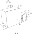
FIG. 2 is a perspective view of a heating unit provided in the notching apparatus for the secondary battery according to the first embodiment of the present invention. -
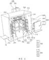
FIG. 3 is a partial exploded perspective view of the heating unit provided in the notching apparatus for the secondary battery according to the first embodiment of the present invention. -
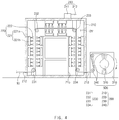
FIG. 4 is a cross-sectional view of the heating unit provided in the notching apparatus for the secondary battery according to the first embodiment of the present invention. -
FIG. 5 is a partial enlarged view of the heating unit provided in the notching apparatus for the secondary battery according to the first embodiment of the present invention. -
FIG. 6 is a flowchart illustrating a notching method for a secondary battery according to a second embodiment of the present invention. - Hereinafter, embodiments of the present invention will be described in detail with reference to the accompanying drawings in such a manner that the technical idea of the present invention may easily be carried out by a person with ordinary skill in the art to which the invention pertains. The present invention may, however, be embodied in different forms and should not be construed as limited to the embodiments set forth herein. In the drawings, anything unnecessary for describing the present invention will be omitted for clarity, and also like reference numerals in the drawings denote like elements.
- An
electrode 10 according to the present invention comprises a collector and an electrode active material applied to one surface or both surfaces of the collector. That is, theelectrode 10 may be manufactured by applying the electrode active material to the one surface or both the surfaces of the collector. - A notching process of sharing the electrode into a predetermined electrode pattern is performed on the electrode manufactured as described above. Here, a notching apparatus for the secondary battery is used.
- Particularly, in the notching apparatus for the secondary battery, the electrode may be shared into the predetermined pattern, and the shared electrode may be dried to significantly improve work efficiency.
- That is, as illustrated in
FIG. 1 , a notching apparatus for a secondary battery according to a first embodiment of the present invention comprises a notchingunit 100 sharing anelectrode 10 into a predetermined electrode pattern, aheating unit 200 drying the electrode processed by the notchingunit 100, and acollecting unit 300 collecting the electrode 20 dried by theheating unit 200. - Referring to
FIG. 1 , the notchingunit 100 comprises an unwindingpart 110 around which a non-process film is wound in a roll shape, afilm feeding part 120 grasping the electrode film unwound from the unwindingpart 110 to continuously repeatedly transfer the electrode by a predetermined distance in a horizontal direction, a notchingprocessing part 130 disposed between the unwindingpart 110 and thefilm feeding part 120 to share the electrode film transferred by thefilm feeding part 120 into a predetermined electrode pattern so as to form an electrode, and avision inspection part 140 disposed on the other side of thefilm feeding part 120 to photograph an electrode part of the shared electrode so as to inspect the electrode. - As illustrated in
FIGS. 2 and3 , theheating unit 200 is configured to quickly dry the moisture remaining on theelectrode 10 passing through the notchingunit 100 and comprises aheating body 210 through which theelectrode 10 supplied from the notchingunit 100 passes and aheating member 220 directly heating the surface of theelectrode 10 passing through theheating body 210 to dry the moisture remaining on theelectrode 10. - The
heating body 210 has a rectangular box shape and comprises a dryingspace 211 through which theelectrode 10 supplied from the notchingunit 100 passes, aninlet 212 which is provided in a left surface (a left surface of the heating body when viewed inFIG. 1 ) and through which theelectrode 10 supplied from the notchingunit 100 is introduced, anoutlet 213 which is provided in a right surface (a right surface of the heating body when viewed inFIG. 1 ) and through which theelectrode 10 introduced into the dryingspace 211 is discharged, and acover 214 coupled to one surface (a front surface of the heating body when viewed inFIG. 1 ) between theinlet 212 and theoutlet 213. Here, thecover 214 may be separated from the heating body 21 to open the dryingspace 211 so that the dryingspace 211 communicates with the outside. - In the
heating body 210 having the above-described structure, theelectrode 10 is introduced into the dryingspace 211 through theinlet 212, and then, theelectrode 10 introduced into the dryingspace 211 is discharged through theoutlet 213. Here, thecover 214 may be attached and detached to open and close the dryingspace 211. - The
cover 214 may be made of a transparent or translucent heat-resistant material. Thus, the dryingspace 211 may be easily recognized from the outside. - The
heating member 220 may be configured to directly dry the electrode introduced into the dryingspace 211 of the heating body. Theheating member 220 comprises a mountingpart 221 provided in the dryingspace 211 and a plurality ofheating lamps 222 installed in the mountingpart 221 and disposed close to the surface of theelectrode 10 to directly heat and dry the surface of theelectrode 10 and thereby to remove the moisture remaining on theelectrode 10. - The mounting
part 221 may have a structure in which the plurality ofheating lamps 222 provided in the dryingspace 211 are more easily replaced. For example, the mountingpart 221 comprises a fixedplate 221a provided in the dryingspace 211 and aguide plate 221b which is slidably coupled to the fixedplate 221a and on which the plurality ofheating lamps 222 are installed. That is, referring toFIGS. 4 and5 , aguide groove 221a-1 is formed in the fixedplate 221a, and aguide protrusion 221b-1 slidably coupled to theguide groove 221a-1 is formed on theguide plate 221b. - Thus, in the mounting
part 221, theguide plate 221b may be easily taken out of the dryingspace 211 by theguide groove 221a-1 and theguide protrusion 221b-1. As a result, the plurality ofheating lamps 222 installed on theguide plate 221b may be easily replaced outside the dryingspace 211 to facilitate maintenance. - Here, the
guide plate 221b may be coupled to the fixedplate 221a so as to be slid toward thecover 214. Thus, the plurality ofheating lamps 222 installed on theguide plate 221b may be taken out of the dryingspace 211 only by the small movement of theguide plate 221b. - In the mounting
part 221, when the plurality ofheating lamps 222 provided on theguide plate 221b and the surface of theelectrode 10 do not match each other, theguide plate 221b may be slid along theguide groove 221a-1 of the fixedplate 221a to allow the plurality ofheating lamps 222 and the surface of theelectrode 10 to match each other. - The
guide plate 221b may be detachably coupled to the fixedplate 221a. That is, when the plurality ofheating lamps 222 are replaced, the replacement of the plurality ofheating lamps 222 is performed outside the dryingspace 211 after theguide plate 221b is detached from the fixedplate 221a. Then, when the replacement of theheating lamps 222 is completed, theguide plate 221b is coupled again to the fixedplate 221a. - Each of the fixed
plate 221a and theguide plate 221b of the mountingpart 211 may be a heatsink plate which absorbs heat generated in the plurality ofheating lamps 222 to release the heat to the outside. Thus, an increase in temperature of theheating lamps 222 may be suppressed. - As illustrated in
FIGS. 4 and5 , each of theheating lamps 222 comprises a power source part 222a installed on theguide plate 221b to receive current from the outside and alight source part 222b emitting light by the current supplied from the power source part 222a. - Here, the
light source part 222b may be disposed close to the surface of theelectrode 10. For example, thelight source part 222b may be disposed to be spaced a distance 'α', which is illustrated inFIG. 4 , from the surface of theelectrode 10. That is, thelight source part 222b may be disposed a distance of 2 mm to 10 mm from the surface of theelectrode 10. That is, when thelight source part 222b is spaced a distance of 2 mm or less from the surface of theelectrode 10, theelectrode 10 may be damaged due to friction between thelight source part 222b and theelectrode 10. When thelight source part 222b is spaced a distance of 10 mm or more from the surface of theelectrode 10, the light emitted from thelight source part 222b is irradiated onto the surface of theelectrode 10 in a diffused state to deteriorate a drying rate of theelectrode 10. - Thus, the
heating lamp 222 may be disposed to be spaced a distance of 2 mm to 10 mm from the surface of theelectrode 10 to stably dry theelectrode 10 and thereby to remove the moisture remaining on theelectrode 10 without damaging theelectrode 10. - The
heating lamp 222 may be a far-infrared lamp or a xenon light. That is, the far-infrared lamp may emit an infrared ray having a wavelength of 25 µm or more, which is longer than that of the visible light and thus may be invisible through the eye, have the large heat effect, and have the high penetration property to realize the good drying efficiency. Also, the xenon light may be brighter than the filament and also may emit light from the bulb, but from the filament, to more widely and quickly dry the surface of the electrode. Particularly, the xenon light may have the lifespan longer than that of the filament to greatly reduce the maintenance cost. - The plurality of
heating lamps 222 may be regularly or irregularly installed on theguide plate 221b. Particularly, a distance between the plurality ofheating lamps 222, which are regularly or irregularly installed on theguide plate 221b, may be a distance in which portions of the light irradiated onto theelectrode 10 overlap each other. Thus, the entire surface of theelectrode 10 may be directly heated and dried. - The
heating unit 200 may further comprise a transfer roller transferring the electrode introduced into the dryingspace 211 and constantly maintaining tension force. Particularly, thetransfer roller 230 may have a structure in which theelectrode 10 introduced into the dryingspace 211 is circulated with a maximally long length. Theheating member 220 may directly heat theelectrode 10 transferred along thetransfer roller 230 to more effectively remove the moisture remaining on theelectrode 10. - For example, the
transfer roller 230 comprises afirst transfer roller 231 disposed on a side of theinlet 212 of the dryingspace 211, asecond transfer roller 232 disposed on an upper portion of the left surface of the dryingspace 211, athird transfer roller 233 disposed on an upper portion of the right surface of the dryingspace 211, and afourth transfer roller 234 disposed on a side of theoutlet 213 of the dryingspace 211. - Here, the
inlet 212 is disposed on a lower end of the left surface of the dryingspace 211, and theoutlet 213 is disposed on a lower end of the right surface of the dryingspace 211. - Thus, the
transfer roller 230 may transfer the electrode introduced into the dryingspace 211 along the left surface, a top surface, and the right surface of the drying space. As a result, a length and a residence time of the electrode introduced into the dryingspace 211 may increase, and thus, a drying time through theheating member 220 may naturally increase. - The
heating member 220 may be provided between thefirst transfer roller 231 and thesecond transfer roller 232, between thesecond transfer roller 232 and thethird transfer roller 233, and between thethird transfer roller 233 and thefourth transfer roller 234. Thus, theelectrode 10 transferred along the first tofourth transfer rollers heating member 220 to completely dry the moisture remaining on theelectrode 10. - The
heating member 220 may dry both surfaces of theelectrode 10 at the same time so that the heating rate of theelectrode 10 increases. That is, theheating member 220 may be disposed to correspond to both the surfaces of theelectrode 10 to dry both the surfaces of theelectrode 10 at the same time. - Here, the
heating member 220 drying one surface (an outer surface of the electrode when viewed inFIG. 3 ) of theelectrode 10, which faces the wall of the dryingspace 211, may be installed on the wall of the dryingspace 211. Theheating member 220 drying the other surface (an inner surface of the electrode when viewed inFIG. 3 ) of theelectrode 10 may be installed on anauxiliary frame 215 provided in the dryingspace 211. Thus, all theheating members 220 provided in the dryingspace 211 may be stably installed. - The
heating unit 200 may further comprise anexhaust member 240 discharging air containing the moisture in the dryingspace 211 to the outside. Theheating unit 200 may quickly discharge the moisture evaporated from the surface of theelectrode 10 through theexhaust member 240 to increase in drying rate of theelectrode 10. - Particularly, the
exhaust member 240 is disposed on the outer surface of theheating body 210, more preferably, an upper portion of a rear surface of theheating body 210 when viewed inFIG. 2 . That is, when theexhaust member 240 is disposed on the top surface of theheating body 210, hot air in the dryingspace 211 and cold air outside theexhaust member 240 may contact each other to generate droplets on a boundary line between theheating body 210 and theexhaust member 240. To prevent this phenomenon, theexhaust member 240 may be installed on the upper portion of the rear surface of theheating body 210 so that the hot air in the dryingspace 211 is bypassed to a lower portion of the dryingspace 211 to decrease in temperature and then is discharged to prevent the droplets from being generated on the boundary line between theheating body 210 and theexhaust member 240. - As described above, the
exhaust member 240 comprises anexhaust duct 241 disposed on the outer surface of theheating body 210 to discharge the air within the dryingspace 211 to the outside and anexhaust pump 242 generating suction force to forcibly discharge the air within the dryingspace 211 to the outside through theexhaust duct 241. Thus, the air containing the moisture within the dryingspace 211 may be more quickly forcibly discharged to the outside, and thus, the drying rate may increase. - Referring to
FIGS. 1 and2 , the collectingunit 300 is configured to collect the driedelectrode 10 dried by theheating unit 200 and comprises a collectingbody 310 comprising a bottom plate and a support plate disposed to correspond to each of both sides of the bottom plate, a collectingroller 320 rotatably disposed between the support plates of the collectingroller 310 to wind and collect theelectrode 10 discharged from theheating unit 200, a collectingmotor 330 rotating the collectingroller 320 to wind theelectrode 10, and a collectingguide roller 340 guiding theelectrode 10 collected from the collectingroller 320 and adjusting tension force. - The collecting
unit 300 may stably collect theelectrode 10 discharged from theheating unit 200 while maintaining the tension force. - In the electrode drying system for the secondary battery comprising the above-described constituents according to the first embodiment of the present invention, the surface of the electrode may be directly heated and dried to more quickly dry the moisture remaining on the electrode, thereby reducing the drying time and improving the productivity.
- Hereinafter, a notching method using the electrode notching apparatus according to the first embodiment of the present invention will be described.
- As illustrated in
FIG. 6 , a notching method for a secondary battery according to a second embodiment of the present invention comprises: a notching step (S10) of sharing an electrode into a predetermined electrode pattern through a notching unit; a drying step (S20) of directly heating a surface of the electrode processed in the notching step by using a heating unit to dry moisture remaining on the electrode; and a collecting step (S30) of collecting the electrode dried in the drying step into a collecting unit. - In the notching step (S10), a non-processed electrode film wound in a roll shape is supplied through a unwinding part, the non-processed electrode film supplied from the unwinding part is horizontally transferred by a predetermined distance through a film feeding part, the notching processing part shares the non-processed electrode film, which is horizontally transferred by the film feeding part, into the predetermined electrode pattern to form an electrode, and whether the shared electrode is defective is inspected through a vision inspection part.
- In the drying step (S20), the electrode, on which the notching step (S10) is performed, is introduced into a drying
space 211 through aninlet 212 formed in aheating body 210, and theelectrode 10 introduced into the dryingspace 211 is transferred along first tofourth transfer rollers transfer roller 230. Then, theelectrode 10 transferred along the first tofourth transfer rollers heating members 220, which are respectively disposed between thefirst transfer roller 231 and thesecond transfer roller 232, between thesecond transfer roller 232 and thethird transfer roller 233, and between thethird transfer roller 233 and thefourth transfer roller 234, and the dried electrode is discharged through anoutlet 213 of theheating body 210. - Here, each of the
heating members 220 may directly heat and dry both surfaces of theelectrode 10 through a plurality ofheating lamps 222 to quickly remove moisture remaining on theelectrode 10, and anexhaust member 240 may discharge air within the dryingspace 211 to the outside to increase in drying rate of theelectrode 10. - Here, if there is a heating lamp, of which lifespan is ended, of the plurality of
heating lamps 222, the plurality ofheating lamps 222 may be taken out of the dryingspace 211 through a fixedplate 221a and aguide plate 221b of a mountingpart 221 provided in theheating member 220. Thus, the heating lamp may be easily replaced. - In the collecting step (S30), the
electrode 10 discharged through theoutlet 213 of theheating body 210 is wound to be collected into the collectingunit 300. - Accordingly, the scope of the present invention is defined by the appended claims rather than the foregoing description and the exemplary embodiments described therein. Various modifications made within the meaning of an equivalent of the claims of the invention and within the claims are to be regarded to be in the scope of the present invention.
Claims (14)
- A notching apparatus for a secondary battery, the notching apparatus comprising:a notching unit sharing an electrode into a predetermined pattern;a heating unit drying the electrode processed by the notching unit; anda collecting unit collecting the electrode dried by the heating unit,wherein the heating unit comprises:a heating body having a drying space through which the electrode shared by the notching unit passes; andheating members directly heating a surface of the electrode passing through the drying space to dry moisture remaining on the electrode.
- The notching apparatus of claim 1, wherein each of the heating members comprises:a mounting part provided in the drying space; anda plurality of heating lamps installed on the mounting part and disposed close to the surface of the electrode to directly heat the surface of the electrode so as to dry the moisture remaining on the electrode.
- The notching apparatus of claim 2, wherein the mounting part comprises:a fixed plate provided in the drying space; anda guide plate which is slidably coupled to the fixed plate and on which the plurality of heating lamps are installed.
- The notching apparatus of claim 3, wherein the heating body comprises:an inlet which is provided in a left surface of the heating body and through which the electrode supplied from the notching unit is introduced;an outlet which is provided in a right surface of the heating body and through which the electrode introduced into the drying space is discharged; anda cover coupled to one surface between the inlet and the outlet,wherein the guide plate is coupled to the fixed plate so as to be slid in a direction of the cover.
- The notching apparatus of claim 4, wherein the heating unit further comprises a transfer roller transferring the electrode introduced into the drying space,
wherein the transfer roller comprises: a first transfer roller disposed at an inlet-side of the drying space; a second transfer roller disposed on an upper portion of the left surface of the drying space; a third transfer roller disposed on an upper portion of the right surface of the drying space; and a fourth transfer roller disposed at an outlet-side of the drying space,
the heating members are respectively provided between the first transfer roller and the second transfer roller, between the second transfer roller and the third transfer roller, and between the third transfer roller and the fourth transfer roller, and
the electrode introduced into the drying space is dried by the heating members while being transferred along the first to fourth transfer rollers. - The notching apparatus of claim 5, wherein the heating members are respectively provided to correspond to both surfaces of the electrode so as to dry both the surfaces of the electrode at the same time.
- The notching apparatus of claim 6, wherein the heating member drying one surface of the electrode, which faces a wall of the drying space, is installed on the wall of the drying space, and
the heating member drying the other surface of the electrode is installed on an auxiliary frame provided in the drying space. - The notching apparatus of claim 2, wherein the heating lamp is spaced a distance of 2 mm to 10 mm from the surface of the electrode.
- The notching apparatus of claim 1, wherein the heating unit further comprises an exhaust member discharging air containing the moisture within the drying space to the outside.
- The notching apparatus of claim 9, wherein the exhaust member is disposed on an outer surface of the heating body.
- The notching apparatus of claim 10, wherein the exhaust member comprise:an exhaust duct disposed on the outer surface of the heating body to discharge the air within the drying space to the outside; andan exhaust pump generating suction force to forcibly discharge the air within the drying space to the outside through the exhaust duct.
- The notching apparatus of claim 2, wherein the heating lamp comprises a far-infrared lamp.
- The notching apparatus of claim 2, wherein the heating lamp comprises a xenon light.
- A notching method for a secondary battery, the notching method comprising:a notching step (S10) of sharing an electrode into a predetermined electrode pattern through a notching unit;a drying step (S20) of directly heating a surface of the electrode processed in the notching step by using a heating unit to dry moisture remaining on the electrode; anda collecting step (S30) of collecting the electrode dried in the drying step into a collecting unit,wherein the heating unit comprises:a heating body having a drying space through which the electrode supplied in the notching step (S10) passes; anda heating member directly heating the surface of the electrode passing through the drying space to dry the moisture remaining on the electrode.
Priority Applications (1)
| Application Number | Priority Date | Filing Date | Title |
|---|---|---|---|
| PL18900666T PL3595049T3 (en) | 2018-01-16 | 2018-12-19 | Notching apparatus and method for secondary battery |
Applications Claiming Priority (2)
| Application Number | Priority Date | Filing Date | Title |
|---|---|---|---|
| KR1020180005601A KR102299988B1 (en) | 2018-01-16 | 2018-01-16 | Notching device and method for secondary battery |
| PCT/KR2018/016227 WO2019143033A1 (en) | 2018-01-16 | 2018-12-19 | Notching apparatus and notching method for secondary battery |
Publications (3)
| Publication Number | Publication Date |
|---|---|
| EP3595049A1 true EP3595049A1 (en) | 2020-01-15 |
| EP3595049A4 EP3595049A4 (en) | 2020-07-15 |
| EP3595049B1 EP3595049B1 (en) | 2021-04-14 |
Family
ID=67301469
Family Applications (1)
| Application Number | Title | Priority Date | Filing Date |
|---|---|---|---|
| EP18900666.1A Active EP3595049B1 (en) | 2018-01-16 | 2018-12-19 | Notching apparatus and method for secondary battery |
Country Status (6)
| Country | Link |
|---|---|
| US (1) | US11581520B2 (en) |
| EP (1) | EP3595049B1 (en) |
| KR (1) | KR102299988B1 (en) |
| CN (1) | CN110892558B (en) |
| PL (1) | PL3595049T3 (en) |
| WO (1) | WO2019143033A1 (en) |
Cited By (1)
| Publication number | Priority date | Publication date | Assignee | Title |
|---|---|---|---|---|
| EP3641023A4 (en) * | 2018-05-23 | 2020-12-09 | Lg Chem, Ltd. | SECONDARY BATTERY NOTCHING DEVICE AND SECONDARY BATTERY NOTCHING PROCEDURE |
Families Citing this family (4)
| Publication number | Priority date | Publication date | Assignee | Title |
|---|---|---|---|---|
| KR102299988B1 (en) * | 2018-01-16 | 2021-09-09 | 주식회사 엘지에너지솔루션 | Notching device and method for secondary battery |
| KR102953630B1 (en) * | 2021-03-03 | 2026-04-15 | 주식회사 엘지에너지솔루션 | Vacuum drying apparatus for roll-to-roll electrode and vacuum drying method thereof |
| KR102378979B1 (en) * | 2021-07-26 | 2022-03-25 | (주)미디어테크 | In-line manufacturing apparatus for lithium batteries |
| KR20240163341A (en) * | 2023-05-10 | 2024-11-19 | 주식회사 엘지에너지솔루션 | Electrode Sheet Processing Device Equipped With Multiple Detection Members And Electrode Sheet Processing Method Using It |
Family Cites Families (54)
| Publication number | Priority date | Publication date | Assignee | Title |
|---|---|---|---|---|
| US4654979A (en) * | 1985-07-22 | 1987-04-07 | Candor James T | Electrostatic method and apparatus for treating material |
| US3952421A (en) * | 1974-10-18 | 1976-04-27 | Chemetron Corporation | Dielectric heating arrangement for drying a continuously moving web of material |
| JPS5850816A (en) * | 1981-09-21 | 1983-03-25 | Tokyo Denpa Kk | Crystal oscillator |
| USH923H (en) * | 1989-11-13 | 1991-06-04 | The United States Of America As Represented By The Secretary Of The Army | Accelerated fabric drying and decontaminating apparatus and method |
| WO1997030487A1 (en) * | 1996-02-16 | 1997-08-21 | Fuji Photo Film Co., Ltd. | Nonaqueous secondary battery |
| US6053953A (en) * | 1997-02-14 | 2000-04-25 | Fuji Photo Film Co., Ltd. | Nonaqueous secondary battery and process for preparation thereof |
| US6159253A (en) * | 1998-01-07 | 2000-12-12 | Medtronic, Inc. | Thermally formed tab slots in a separator for a spirally-wound electrochemical cell |
| US6192599B1 (en) * | 1998-09-23 | 2001-02-27 | Bgf Industries, Inc. | Drying process for woven fabric intended for use as a reinforcing laminate in printed circuit boards |
| KR100280718B1 (en) * | 1998-11-03 | 2001-03-02 | 김순택 | Stabilization method of lithium ion secondary battery |
| HUP0101103A2 (en) * | 2000-03-17 | 2001-11-28 | Sony Corporation | Method and equipment for manufacturing thereof dry reserve accumulators |
| JP2002318071A (en) | 2001-04-18 | 2002-10-31 | Eco Net:Kk | Sterilizing drying device |
| JP2003132878A (en) | 2001-10-22 | 2003-05-09 | Toyota Motor Corp | Electrode manufacturing apparatus and electrode manufacturing method |
| JP4322538B2 (en) * | 2003-04-08 | 2009-09-02 | パイオニア株式会社 | Method for manufacturing light-emitting display panel |
| JP4790207B2 (en) * | 2003-05-29 | 2011-10-12 | パナソニック株式会社 | Method for producing positive electrode for alkaline storage battery |
| WO2005024950A1 (en) * | 2003-09-05 | 2005-03-17 | Fujitsu Limited | Semiconductor device and method for manufacturing same |
| US7446006B2 (en) * | 2005-09-14 | 2008-11-04 | Freescale Semiconductor, Inc. | Semiconductor fabrication process including silicide stringer removal processing |
| KR101293567B1 (en) | 2006-02-21 | 2013-08-06 | 삼성디스플레이 주식회사 | Manufacturing method of display device |
| TWM300058U (en) * | 2006-04-25 | 2006-11-01 | Chuen-Wan Ye | Heating device |
| CN101360965B (en) * | 2006-05-18 | 2010-12-22 | 富士胶片株式会社 | Method and apparatus for drying object to be dried |
| KR20090114787A (en) * | 2008-04-30 | 2009-11-04 | 삼성전자주식회사 | Inkjet Printheads and Manufacturing Method Thereof |
| CN201408801Y (en) * | 2009-05-19 | 2010-02-17 | 许刚 | Far infrared drying device for coating lithium battery pole piece |
| JP5249916B2 (en) * | 2009-12-24 | 2013-07-31 | 三菱重工業株式会社 | Electrode dryer |
| JP5509998B2 (en) * | 2010-03-31 | 2014-06-04 | 日産自動車株式会社 | Electrode manufacturing apparatus and electrode manufacturing method |
| US20120043639A1 (en) * | 2010-08-19 | 2012-02-23 | MOS Art Pack Corporation | Fabricating method and structure of submount |
| KR101204598B1 (en) * | 2010-08-27 | 2012-11-23 | 삼성전기주식회사 | Doping apparatus for manufacturing electrode of enegy storage device, and method for manufacturing the electrode with the same |
| US9005400B2 (en) * | 2010-08-30 | 2015-04-14 | Renewable Fuel Technologies, Inc. | Device and method for controlling the conversion of biomass to biofuel |
| KR101175031B1 (en) * | 2010-12-30 | 2012-08-17 | 삼성에스디아이 주식회사 | Method of fabricating electrode plate and electrode plate fabricated by the same method |
| JP5421934B2 (en) | 2011-01-13 | 2014-02-19 | 東京エレクトロン株式会社 | Electrode manufacturing apparatus and electrode manufacturing method |
| KR101077069B1 (en) | 2011-02-28 | 2011-10-26 | (주)엠오텍 | Vacuum Drying Device and Drying Method of Anode Plate for Secondary Battery |
| US20120251858A1 (en) * | 2011-04-04 | 2012-10-04 | Rohm Co., Ltd. | Laminated type energy device, chip type energy device, energy device electrode structure and fabrication method of the laminated type energy device |
| CN102824984A (en) * | 2011-06-16 | 2012-12-19 | 赵宽 | Coating internal heat drying method lithium ion battery pole piece coater |
| KR101303060B1 (en) * | 2011-08-26 | 2013-09-03 | (주)피엔티 | Apparatus for coating both surfaces of thin material |
| CN202284725U (en) * | 2011-09-30 | 2012-06-27 | 福州小糸大亿车灯有限公司 | Multipurpose HID xenon illuminating lamp |
| KR101335704B1 (en) * | 2012-02-01 | 2013-12-04 | 삼성중공업 주식회사 | Drying device |
| KR101170622B1 (en) * | 2012-04-13 | 2012-08-03 | (주)엠오텍 | Group type drying and transporting device of pole plate for secondary battery and method |
| JP6075753B2 (en) * | 2012-09-19 | 2017-02-08 | Necエナジーデバイス株式会社 | Method for producing positive electrode for lithium ion secondary battery and method for producing lithium ion secondary battery |
| US9096079B2 (en) * | 2012-10-11 | 2015-08-04 | Eastman Kodak Company | Dryer impinging heating liquid onto moistened medium |
| JP6225117B2 (en) * | 2012-11-07 | 2017-11-01 | 日本碍子株式会社 | Infrared heating device and drying furnace |
| JP5984643B2 (en) * | 2012-11-29 | 2016-09-06 | 株式会社メイコー | Electrode sheet drying apparatus and electrode sheet drying method |
| KR102007698B1 (en) * | 2013-01-23 | 2019-08-06 | 삼성에스디아이 주식회사 | Dryer for electrode substrate of rechargeable battery and controlling method of the same |
| KR101572720B1 (en) | 2013-09-13 | 2015-11-27 | 주식회사 엘지화학 | Apparatus for winding Electrode assembly |
| KR101761973B1 (en) * | 2013-11-29 | 2017-07-26 | 주식회사 엘지화학 | Notching apparatus of laser |
| US20170005318A1 (en) * | 2014-03-25 | 2017-01-05 | Nec Corporation | Laminated-type battery and method for manufacturing the same |
| JP2016027562A (en) * | 2014-07-04 | 2016-02-18 | 株式会社半導体エネルギー研究所 | Secondary battery manufacturing method and manufacturing apparatus |
| KR101556857B1 (en) * | 2014-09-29 | 2015-10-01 | 엘지전자 주식회사 | Manufactoring system of anode for cable type secondary battery |
| KR101704166B1 (en) * | 2015-02-04 | 2017-02-08 | 김지혜 | LED socket for fishing float with holder type electrode |
| KR20160114857A (en) | 2015-03-25 | 2016-10-06 | 주식회사 비츠로셀 | current collector for enhancing non-magnetic and manufacturing method therewith |
| KR101561622B1 (en) * | 2015-04-08 | 2015-10-20 | 농업회사법인주식회사바로원푸드 | A apparatus for the preparation of a dried laver for sushi, manufacturing method thereof and the dried laver for sushi prepared therefrom |
| CN107408666B (en) * | 2015-09-25 | 2021-01-15 | 株式会社东芝 | Electrode for nonaqueous electrolyte battery, and battery pack |
| CN106099046B (en) * | 2016-08-19 | 2018-11-09 | 深圳市信宇人科技股份有限公司 | The continuous complete automatic assembly line of electrodes of lithium-ion batteries |
| CN111511617B (en) * | 2017-12-27 | 2023-01-06 | 罗伯特·博世有限公司 | Real-time pressure-volume curve generation for hydraulic systems |
| KR102299988B1 (en) * | 2018-01-16 | 2021-09-09 | 주식회사 엘지에너지솔루션 | Notching device and method for secondary battery |
| KR102306546B1 (en) * | 2018-05-23 | 2021-09-30 | 주식회사 엘지에너지솔루션 | Notching device and method for secondary battery |
| KR102923041B1 (en) * | 2020-08-05 | 2026-02-04 | 현대자동차 주식회사 | Secondary battery electrode manufacturing system and electrode manufacturing method using the same |
-
2018
- 2018-01-16 KR KR1020180005601A patent/KR102299988B1/en active Active
- 2018-12-19 US US16/604,386 patent/US11581520B2/en active Active
- 2018-12-19 EP EP18900666.1A patent/EP3595049B1/en active Active
- 2018-12-19 WO PCT/KR2018/016227 patent/WO2019143033A1/en not_active Ceased
- 2018-12-19 CN CN201880045589.3A patent/CN110892558B/en active Active
- 2018-12-19 PL PL18900666T patent/PL3595049T3/en unknown
Cited By (2)
| Publication number | Priority date | Publication date | Assignee | Title |
|---|---|---|---|---|
| EP3641023A4 (en) * | 2018-05-23 | 2020-12-09 | Lg Chem, Ltd. | SECONDARY BATTERY NOTCHING DEVICE AND SECONDARY BATTERY NOTCHING PROCEDURE |
| US11594713B2 (en) | 2018-05-23 | 2023-02-28 | Lg Energy Solution, Ltd. | Notching apparatus and method for secondary battery |
Also Published As
| Publication number | Publication date |
|---|---|
| EP3595049A4 (en) | 2020-07-15 |
| US20200161629A1 (en) | 2020-05-21 |
| KR20190087157A (en) | 2019-07-24 |
| KR102299988B1 (en) | 2021-09-09 |
| CN110892558A (en) | 2020-03-17 |
| CN110892558B (en) | 2022-11-25 |
| EP3595049B1 (en) | 2021-04-14 |
| WO2019143033A1 (en) | 2019-07-25 |
| PL3595049T3 (en) | 2021-11-15 |
| US11581520B2 (en) | 2023-02-14 |
Similar Documents
| Publication | Publication Date | Title |
|---|---|---|
| EP3595049B1 (en) | Notching apparatus and method for secondary battery | |
| EP3496187B1 (en) | Electrode heating device, and secondary battery manufacturing system including same | |
| US11594713B2 (en) | Notching apparatus and method for secondary battery | |
| TWI429871B (en) | Electrode dryer | |
| KR101810146B1 (en) | Dryer used in manufacturing electrode of secondary battery | |
| CN120479720A (en) | Coating apparatus | |
| WO2020106033A1 (en) | Method for manufacturing cylindrical battery and drying apparatus for performing same | |
| US20240272562A1 (en) | Substrate treatment apparatus | |
| KR20220136082A (en) | Electrode drying device | |
| KR20230090522A (en) | Electrod notching equipment and controlling method thereof | |
| KR102502275B1 (en) | Coanda effect hot air blower and apparatus for drying electrode of secondary battery | |
| EP4589233B1 (en) | Electrode manufacturing system and method for manufacturing an electrode | |
| KR102891247B1 (en) | Electrode drying device | |
| KR20250133820A (en) | Laser drying equipment | |
| WO2019035564A1 (en) | Electrode heating device, and secondary battery manufacturing system including same | |
| KR20260013770A (en) | Electrode manufacturing method and electrode manufacturing device | |
| KR20240168661A (en) | Electrode drying device | |
| WO2024242225A1 (en) | Electrode drying apparatus | |
| WO2022191411A1 (en) | Electrode drying device |
Legal Events
| Date | Code | Title | Description |
|---|---|---|---|
| STAA | Information on the status of an ep patent application or granted ep patent |
Free format text: STATUS: THE INTERNATIONAL PUBLICATION HAS BEEN MADE |
|
| PUAI | Public reference made under article 153(3) epc to a published international application that has entered the european phase |
Free format text: ORIGINAL CODE: 0009012 |
|
| STAA | Information on the status of an ep patent application or granted ep patent |
Free format text: STATUS: REQUEST FOR EXAMINATION WAS MADE |
|
| 17P | Request for examination filed |
Effective date: 20191010 |
|
| AK | Designated contracting states |
Kind code of ref document: A1 Designated state(s): AL AT BE BG CH CY CZ DE DK EE ES FI FR GB GR HR HU IE IS IT LI LT LU LV MC MK MT NL NO PL PT RO RS SE SI SK SM TR |
|
| AX | Request for extension of the european patent |
Extension state: BA ME |
|
| A4 | Supplementary search report drawn up and despatched |
Effective date: 20200617 |
|
| RIC1 | Information provided on ipc code assigned before grant |
Ipc: H05B 3/00 20060101ALI20200610BHEP Ipc: B26D 7/27 20060101ALI20200610BHEP Ipc: B26D 3/14 20060101ALI20200610BHEP Ipc: H01M 4/04 20060101AFI20200610BHEP Ipc: H01M 10/04 20060101ALI20200610BHEP |
|
| GRAP | Despatch of communication of intention to grant a patent |
Free format text: ORIGINAL CODE: EPIDOSNIGR1 |
|
| STAA | Information on the status of an ep patent application or granted ep patent |
Free format text: STATUS: GRANT OF PATENT IS INTENDED |
|
| DAV | Request for validation of the european patent (deleted) | ||
| DAX | Request for extension of the european patent (deleted) | ||
| INTG | Intention to grant announced |
Effective date: 20210201 |
|
| GRAS | Grant fee paid |
Free format text: ORIGINAL CODE: EPIDOSNIGR3 |
|
| GRAA | (expected) grant |
Free format text: ORIGINAL CODE: 0009210 |
|
| STAA | Information on the status of an ep patent application or granted ep patent |
Free format text: STATUS: THE PATENT HAS BEEN GRANTED |
|
| AK | Designated contracting states |
Kind code of ref document: B1 Designated state(s): AL AT BE BG CH CY CZ DE DK EE ES FI FR GB GR HR HU IE IS IT LI LT LU LV MC MK MT NL NO PL PT RO RS SE SI SK SM TR |
|
| REG | Reference to a national code |
Ref country code: GB Ref legal event code: FG4D |
|
| REG | Reference to a national code |
Ref country code: CH Ref legal event code: EP |
|
| REG | Reference to a national code |
Ref country code: DE Ref legal event code: R096 Ref document number: 602018015669 Country of ref document: DE |
|
| REG | Reference to a national code |
Ref country code: IE Ref legal event code: FG4D |
|
| REG | Reference to a national code |
Ref country code: AT Ref legal event code: REF Ref document number: 1383257 Country of ref document: AT Kind code of ref document: T Effective date: 20210515 |
|
| REG | Reference to a national code |
Ref country code: DE Ref legal event code: R081 Ref document number: 602018015669 Country of ref document: DE Owner name: LG ENERGY SOLUTION, LTD., KR Free format text: FORMER OWNER: LG CHEM, LTD., SEOUL, KR |
|
| REG | Reference to a national code |
Ref country code: NL Ref legal event code: FP |
|
| REG | Reference to a national code |
Ref country code: LT Ref legal event code: MG9D |
|
| REG | Reference to a national code |
Ref country code: AT Ref legal event code: MK05 Ref document number: 1383257 Country of ref document: AT Kind code of ref document: T Effective date: 20210414 |
|
| PG25 | Lapsed in a contracting state [announced via postgrant information from national office to epo] |
Ref country code: HR Free format text: LAPSE BECAUSE OF FAILURE TO SUBMIT A TRANSLATION OF THE DESCRIPTION OR TO PAY THE FEE WITHIN THE PRESCRIBED TIME-LIMIT Effective date: 20210414 Ref country code: LT Free format text: LAPSE BECAUSE OF FAILURE TO SUBMIT A TRANSLATION OF THE DESCRIPTION OR TO PAY THE FEE WITHIN THE PRESCRIBED TIME-LIMIT Effective date: 20210414 Ref country code: FI Free format text: LAPSE BECAUSE OF FAILURE TO SUBMIT A TRANSLATION OF THE DESCRIPTION OR TO PAY THE FEE WITHIN THE PRESCRIBED TIME-LIMIT Effective date: 20210414 Ref country code: BG Free format text: LAPSE BECAUSE OF FAILURE TO SUBMIT A TRANSLATION OF THE DESCRIPTION OR TO PAY THE FEE WITHIN THE PRESCRIBED TIME-LIMIT Effective date: 20210714 Ref country code: AT Free format text: LAPSE BECAUSE OF FAILURE TO SUBMIT A TRANSLATION OF THE DESCRIPTION OR TO PAY THE FEE WITHIN THE PRESCRIBED TIME-LIMIT Effective date: 20210414 |
|
| PG25 | Lapsed in a contracting state [announced via postgrant information from national office to epo] |
Ref country code: LV Free format text: LAPSE BECAUSE OF FAILURE TO SUBMIT A TRANSLATION OF THE DESCRIPTION OR TO PAY THE FEE WITHIN THE PRESCRIBED TIME-LIMIT Effective date: 20210414 Ref country code: NO Free format text: LAPSE BECAUSE OF FAILURE TO SUBMIT A TRANSLATION OF THE DESCRIPTION OR TO PAY THE FEE WITHIN THE PRESCRIBED TIME-LIMIT Effective date: 20210714 Ref country code: PT Free format text: LAPSE BECAUSE OF FAILURE TO SUBMIT A TRANSLATION OF THE DESCRIPTION OR TO PAY THE FEE WITHIN THE PRESCRIBED TIME-LIMIT Effective date: 20210816 Ref country code: RS Free format text: LAPSE BECAUSE OF FAILURE TO SUBMIT A TRANSLATION OF THE DESCRIPTION OR TO PAY THE FEE WITHIN THE PRESCRIBED TIME-LIMIT Effective date: 20210414 Ref country code: SE Free format text: LAPSE BECAUSE OF FAILURE TO SUBMIT A TRANSLATION OF THE DESCRIPTION OR TO PAY THE FEE WITHIN THE PRESCRIBED TIME-LIMIT Effective date: 20210414 Ref country code: GR Free format text: LAPSE BECAUSE OF FAILURE TO SUBMIT A TRANSLATION OF THE DESCRIPTION OR TO PAY THE FEE WITHIN THE PRESCRIBED TIME-LIMIT Effective date: 20210715 Ref country code: IS Free format text: LAPSE BECAUSE OF FAILURE TO SUBMIT A TRANSLATION OF THE DESCRIPTION OR TO PAY THE FEE WITHIN THE PRESCRIBED TIME-LIMIT Effective date: 20210814 |
|
| REG | Reference to a national code |
Ref country code: DE Ref legal event code: R097 Ref document number: 602018015669 Country of ref document: DE |
|
| RAP2 | Party data changed (patent owner data changed or rights of a patent transferred) |
Owner name: LG ENERGY SOLUTION LTD. |
|
| PG25 | Lapsed in a contracting state [announced via postgrant information from national office to epo] |
Ref country code: SK Free format text: LAPSE BECAUSE OF FAILURE TO SUBMIT A TRANSLATION OF THE DESCRIPTION OR TO PAY THE FEE WITHIN THE PRESCRIBED TIME-LIMIT Effective date: 20210414 Ref country code: ES Free format text: LAPSE BECAUSE OF FAILURE TO SUBMIT A TRANSLATION OF THE DESCRIPTION OR TO PAY THE FEE WITHIN THE PRESCRIBED TIME-LIMIT Effective date: 20210414 Ref country code: EE Free format text: LAPSE BECAUSE OF FAILURE TO SUBMIT A TRANSLATION OF THE DESCRIPTION OR TO PAY THE FEE WITHIN THE PRESCRIBED TIME-LIMIT Effective date: 20210414 Ref country code: RO Free format text: LAPSE BECAUSE OF FAILURE TO SUBMIT A TRANSLATION OF THE DESCRIPTION OR TO PAY THE FEE WITHIN THE PRESCRIBED TIME-LIMIT Effective date: 20210414 Ref country code: SM Free format text: LAPSE BECAUSE OF FAILURE TO SUBMIT A TRANSLATION OF THE DESCRIPTION OR TO PAY THE FEE WITHIN THE PRESCRIBED TIME-LIMIT Effective date: 20210414 Ref country code: CZ Free format text: LAPSE BECAUSE OF FAILURE TO SUBMIT A TRANSLATION OF THE DESCRIPTION OR TO PAY THE FEE WITHIN THE PRESCRIBED TIME-LIMIT Effective date: 20210414 Ref country code: DK Free format text: LAPSE BECAUSE OF FAILURE TO SUBMIT A TRANSLATION OF THE DESCRIPTION OR TO PAY THE FEE WITHIN THE PRESCRIBED TIME-LIMIT Effective date: 20210414 |
|
| PLBE | No opposition filed within time limit |
Free format text: ORIGINAL CODE: 0009261 |
|
| STAA | Information on the status of an ep patent application or granted ep patent |
Free format text: STATUS: NO OPPOSITION FILED WITHIN TIME LIMIT |
|
| 26N | No opposition filed |
Effective date: 20220117 |
|
| PG25 | Lapsed in a contracting state [announced via postgrant information from national office to epo] |
Ref country code: IS Free format text: LAPSE BECAUSE OF FAILURE TO SUBMIT A TRANSLATION OF THE DESCRIPTION OR TO PAY THE FEE WITHIN THE PRESCRIBED TIME-LIMIT Effective date: 20210814 Ref country code: AL Free format text: LAPSE BECAUSE OF FAILURE TO SUBMIT A TRANSLATION OF THE DESCRIPTION OR TO PAY THE FEE WITHIN THE PRESCRIBED TIME-LIMIT Effective date: 20210414 |
|
| PG25 | Lapsed in a contracting state [announced via postgrant information from national office to epo] |
Ref country code: MC Free format text: LAPSE BECAUSE OF FAILURE TO SUBMIT A TRANSLATION OF THE DESCRIPTION OR TO PAY THE FEE WITHIN THE PRESCRIBED TIME-LIMIT Effective date: 20210414 |
|
| REG | Reference to a national code |
Ref country code: CH Ref legal event code: PL |
|
| REG | Reference to a national code |
Ref country code: BE Ref legal event code: MM Effective date: 20211231 |
|
| PG25 | Lapsed in a contracting state [announced via postgrant information from national office to epo] |
Ref country code: LU Free format text: LAPSE BECAUSE OF NON-PAYMENT OF DUE FEES Effective date: 20211219 Ref country code: IE Free format text: LAPSE BECAUSE OF NON-PAYMENT OF DUE FEES Effective date: 20211219 |
|
| PG25 | Lapsed in a contracting state [announced via postgrant information from national office to epo] |
Ref country code: BE Free format text: LAPSE BECAUSE OF NON-PAYMENT OF DUE FEES Effective date: 20211231 |
|
| REG | Reference to a national code |
Ref country code: NL Ref legal event code: PD Owner name: LG ENERGY SOLUTION, LTD.; KR Free format text: DETAILS ASSIGNMENT: CHANGE OF OWNER(S), ASSIGNMENT; FORMER OWNER NAME: LG CHEM, LTD. Effective date: 20221108 |
|
| PG25 | Lapsed in a contracting state [announced via postgrant information from national office to epo] |
Ref country code: LI Free format text: LAPSE BECAUSE OF NON-PAYMENT OF DUE FEES Effective date: 20211231 Ref country code: CH Free format text: LAPSE BECAUSE OF NON-PAYMENT OF DUE FEES Effective date: 20211231 |
|
| REG | Reference to a national code |
Ref country code: DE Ref legal event code: R081 Ref document number: 602018015669 Country of ref document: DE Owner name: LG ENERGY SOLUTION, LTD., KR Free format text: FORMER OWNER: LG CHEM, LTD., SEOUL, KR |
|
| P01 | Opt-out of the competence of the unified patent court (upc) registered |
Effective date: 20230512 |
|
| PG25 | Lapsed in a contracting state [announced via postgrant information from national office to epo] |
Ref country code: CY Free format text: LAPSE BECAUSE OF FAILURE TO SUBMIT A TRANSLATION OF THE DESCRIPTION OR TO PAY THE FEE WITHIN THE PRESCRIBED TIME-LIMIT Effective date: 20210414 |
|
| PG25 | Lapsed in a contracting state [announced via postgrant information from national office to epo] |
Ref country code: HU Free format text: LAPSE BECAUSE OF FAILURE TO SUBMIT A TRANSLATION OF THE DESCRIPTION OR TO PAY THE FEE WITHIN THE PRESCRIBED TIME-LIMIT; INVALID AB INITIO Effective date: 20181219 |
|
| REG | Reference to a national code |
Ref country code: GB Ref legal event code: 732E Free format text: REGISTERED BETWEEN 20230901 AND 20230906 |
|
| PG25 | Lapsed in a contracting state [announced via postgrant information from national office to epo] |
Ref country code: MK Free format text: LAPSE BECAUSE OF FAILURE TO SUBMIT A TRANSLATION OF THE DESCRIPTION OR TO PAY THE FEE WITHIN THE PRESCRIBED TIME-LIMIT Effective date: 20210414 |
|
| PG25 | Lapsed in a contracting state [announced via postgrant information from national office to epo] |
Ref country code: MT Free format text: LAPSE BECAUSE OF FAILURE TO SUBMIT A TRANSLATION OF THE DESCRIPTION OR TO PAY THE FEE WITHIN THE PRESCRIBED TIME-LIMIT Effective date: 20210414 |
|
| PG25 | Lapsed in a contracting state [announced via postgrant information from national office to epo] |
Ref country code: TR Free format text: LAPSE BECAUSE OF FAILURE TO SUBMIT A TRANSLATION OF THE DESCRIPTION OR TO PAY THE FEE WITHIN THE PRESCRIBED TIME-LIMIT Effective date: 20210414 |
|
| PGFP | Annual fee paid to national office [announced via postgrant information from national office to epo] |
Ref country code: NL Payment date: 20251120 Year of fee payment: 8 |
|
| PGFP | Annual fee paid to national office [announced via postgrant information from national office to epo] |
Ref country code: DE Payment date: 20251120 Year of fee payment: 8 |
|
| PGFP | Annual fee paid to national office [announced via postgrant information from national office to epo] |
Ref country code: GB Payment date: 20251120 Year of fee payment: 8 |
|
| PGFP | Annual fee paid to national office [announced via postgrant information from national office to epo] |
Ref country code: IT Payment date: 20251121 Year of fee payment: 8 |
|
| PGFP | Annual fee paid to national office [announced via postgrant information from national office to epo] |
Ref country code: FR Payment date: 20251125 Year of fee payment: 8 |
|
| PGFP | Annual fee paid to national office [announced via postgrant information from national office to epo] |
Ref country code: PL Payment date: 20251124 Year of fee payment: 8 |