EP3595030A1 - Pouch film and manufacturing method therefor - Google Patents
Pouch film and manufacturing method therefor Download PDFInfo
- Publication number
- EP3595030A1 EP3595030A1 EP18899839.7A EP18899839A EP3595030A1 EP 3595030 A1 EP3595030 A1 EP 3595030A1 EP 18899839 A EP18899839 A EP 18899839A EP 3595030 A1 EP3595030 A1 EP 3595030A1
- Authority
- EP
- European Patent Office
- Prior art keywords
- layer
- pouch film
- metal particles
- pouch
- gas barrier
- Prior art date
- Legal status (The legal status is an assumption and is not a legal conclusion. Google has not performed a legal analysis and makes no representation as to the accuracy of the status listed.)
- Granted
Links
Images






Classifications
-
- H—ELECTRICITY
- H01—ELECTRIC ELEMENTS
- H01M—PROCESSES OR MEANS, e.g. BATTERIES, FOR THE DIRECT CONVERSION OF CHEMICAL ENERGY INTO ELECTRICAL ENERGY
- H01M50/00—Constructional details or processes of manufacture of the non-active parts of electrochemical cells other than fuel cells, e.g. hybrid cells
- H01M50/10—Primary casings; Jackets or wrappings
- H01M50/116—Primary casings; Jackets or wrappings characterised by the material
- H01M50/124—Primary casings; Jackets or wrappings characterised by the material having a layered structure
-
- C—CHEMISTRY; METALLURGY
- C23—COATING METALLIC MATERIAL; COATING MATERIAL WITH METALLIC MATERIAL; CHEMICAL SURFACE TREATMENT; DIFFUSION TREATMENT OF METALLIC MATERIAL; COATING BY VACUUM EVAPORATION, BY SPUTTERING, BY ION IMPLANTATION OR BY CHEMICAL VAPOUR DEPOSITION, IN GENERAL; INHIBITING CORROSION OF METALLIC MATERIAL OR INCRUSTATION IN GENERAL
- C23C—COATING METALLIC MATERIAL; COATING MATERIAL WITH METALLIC MATERIAL; SURFACE TREATMENT OF METALLIC MATERIAL BY DIFFUSION INTO THE SURFACE, BY CHEMICAL CONVERSION OR SUBSTITUTION; COATING BY VACUUM EVAPORATION, BY SPUTTERING, BY ION IMPLANTATION OR BY CHEMICAL VAPOUR DEPOSITION, IN GENERAL
- C23C24/00—Coating starting from inorganic powder
- C23C24/08—Coating starting from inorganic powder by application of heat or pressure and heat
- C23C24/082—Coating starting from inorganic powder by application of heat or pressure and heat without intermediate formation of a liquid in the layer
- C23C24/085—Coating with metallic material, i.e. metals or metal alloys, optionally comprising hard particles, e.g. oxides, carbides or nitrides
- C23C24/087—Coating with metal alloys or metal elements only
-
- C—CHEMISTRY; METALLURGY
- C23—COATING METALLIC MATERIAL; COATING MATERIAL WITH METALLIC MATERIAL; CHEMICAL SURFACE TREATMENT; DIFFUSION TREATMENT OF METALLIC MATERIAL; COATING BY VACUUM EVAPORATION, BY SPUTTERING, BY ION IMPLANTATION OR BY CHEMICAL VAPOUR DEPOSITION, IN GENERAL; INHIBITING CORROSION OF METALLIC MATERIAL OR INCRUSTATION IN GENERAL
- C23C—COATING METALLIC MATERIAL; COATING MATERIAL WITH METALLIC MATERIAL; SURFACE TREATMENT OF METALLIC MATERIAL BY DIFFUSION INTO THE SURFACE, BY CHEMICAL CONVERSION OR SUBSTITUTION; COATING BY VACUUM EVAPORATION, BY SPUTTERING, BY ION IMPLANTATION OR BY CHEMICAL VAPOUR DEPOSITION, IN GENERAL
- C23C24/00—Coating starting from inorganic powder
- C23C24/08—Coating starting from inorganic powder by application of heat or pressure and heat
-
- C—CHEMISTRY; METALLURGY
- C23—COATING METALLIC MATERIAL; COATING MATERIAL WITH METALLIC MATERIAL; CHEMICAL SURFACE TREATMENT; DIFFUSION TREATMENT OF METALLIC MATERIAL; COATING BY VACUUM EVAPORATION, BY SPUTTERING, BY ION IMPLANTATION OR BY CHEMICAL VAPOUR DEPOSITION, IN GENERAL; INHIBITING CORROSION OF METALLIC MATERIAL OR INCRUSTATION IN GENERAL
- C23C—COATING METALLIC MATERIAL; COATING MATERIAL WITH METALLIC MATERIAL; SURFACE TREATMENT OF METALLIC MATERIAL BY DIFFUSION INTO THE SURFACE, BY CHEMICAL CONVERSION OR SUBSTITUTION; COATING BY VACUUM EVAPORATION, BY SPUTTERING, BY ION IMPLANTATION OR BY CHEMICAL VAPOUR DEPOSITION, IN GENERAL
- C23C26/00—Coating not provided for in groups C23C2/00 - C23C24/00
-
- C—CHEMISTRY; METALLURGY
- C23—COATING METALLIC MATERIAL; COATING MATERIAL WITH METALLIC MATERIAL; CHEMICAL SURFACE TREATMENT; DIFFUSION TREATMENT OF METALLIC MATERIAL; COATING BY VACUUM EVAPORATION, BY SPUTTERING, BY ION IMPLANTATION OR BY CHEMICAL VAPOUR DEPOSITION, IN GENERAL; INHIBITING CORROSION OF METALLIC MATERIAL OR INCRUSTATION IN GENERAL
- C23C—COATING METALLIC MATERIAL; COATING MATERIAL WITH METALLIC MATERIAL; SURFACE TREATMENT OF METALLIC MATERIAL BY DIFFUSION INTO THE SURFACE, BY CHEMICAL CONVERSION OR SUBSTITUTION; COATING BY VACUUM EVAPORATION, BY SPUTTERING, BY ION IMPLANTATION OR BY CHEMICAL VAPOUR DEPOSITION, IN GENERAL
- C23C28/00—Coating for obtaining at least two superposed coatings either by methods not provided for in a single one of groups C23C2/00 - C23C26/00 or by combinations of methods provided for in subclasses C23C and C25C or C25D
- C23C28/02—Coating for obtaining at least two superposed coatings either by methods not provided for in a single one of groups C23C2/00 - C23C26/00 or by combinations of methods provided for in subclasses C23C and C25C or C25D only coatings only including layers of metallic material
- C23C28/023—Coating for obtaining at least two superposed coatings either by methods not provided for in a single one of groups C23C2/00 - C23C26/00 or by combinations of methods provided for in subclasses C23C and C25C or C25D only coatings only including layers of metallic material only coatings of metal elements only
-
- H—ELECTRICITY
- H01—ELECTRIC ELEMENTS
- H01M—PROCESSES OR MEANS, e.g. BATTERIES, FOR THE DIRECT CONVERSION OF CHEMICAL ENERGY INTO ELECTRICAL ENERGY
- H01M10/00—Secondary cells; Manufacture thereof
- H01M10/04—Construction or manufacture in general
- H01M10/0431—Cells with wound or folded electrodes
-
- H—ELECTRICITY
- H01—ELECTRIC ELEMENTS
- H01M—PROCESSES OR MEANS, e.g. BATTERIES, FOR THE DIRECT CONVERSION OF CHEMICAL ENERGY INTO ELECTRICAL ENERGY
- H01M50/00—Constructional details or processes of manufacture of the non-active parts of electrochemical cells other than fuel cells, e.g. hybrid cells
- H01M50/10—Primary casings; Jackets or wrappings
- H01M50/102—Primary casings; Jackets or wrappings characterised by their shape or physical structure
- H01M50/105—Pouches or flexible bags
-
- H—ELECTRICITY
- H01—ELECTRIC ELEMENTS
- H01M—PROCESSES OR MEANS, e.g. BATTERIES, FOR THE DIRECT CONVERSION OF CHEMICAL ENERGY INTO ELECTRICAL ENERGY
- H01M50/00—Constructional details or processes of manufacture of the non-active parts of electrochemical cells other than fuel cells, e.g. hybrid cells
- H01M50/10—Primary casings; Jackets or wrappings
- H01M50/116—Primary casings; Jackets or wrappings characterised by the material
- H01M50/117—Inorganic material
- H01M50/119—Metals
-
- H—ELECTRICITY
- H01—ELECTRIC ELEMENTS
- H01M—PROCESSES OR MEANS, e.g. BATTERIES, FOR THE DIRECT CONVERSION OF CHEMICAL ENERGY INTO ELECTRICAL ENERGY
- H01M50/00—Constructional details or processes of manufacture of the non-active parts of electrochemical cells other than fuel cells, e.g. hybrid cells
- H01M50/10—Primary casings; Jackets or wrappings
- H01M50/116—Primary casings; Jackets or wrappings characterised by the material
- H01M50/121—Organic material
-
- H—ELECTRICITY
- H01—ELECTRIC ELEMENTS
- H01M—PROCESSES OR MEANS, e.g. BATTERIES, FOR THE DIRECT CONVERSION OF CHEMICAL ENERGY INTO ELECTRICAL ENERGY
- H01M50/00—Constructional details or processes of manufacture of the non-active parts of electrochemical cells other than fuel cells, e.g. hybrid cells
- H01M50/10—Primary casings; Jackets or wrappings
- H01M50/116—Primary casings; Jackets or wrappings characterised by the material
- H01M50/124—Primary casings; Jackets or wrappings characterised by the material having a layered structure
- H01M50/126—Primary casings; Jackets or wrappings characterised by the material having a layered structure comprising three or more layers
- H01M50/129—Primary casings; Jackets or wrappings characterised by the material having a layered structure comprising three or more layers with two or more layers of only organic material
-
- H—ELECTRICITY
- H01—ELECTRIC ELEMENTS
- H01M—PROCESSES OR MEANS, e.g. BATTERIES, FOR THE DIRECT CONVERSION OF CHEMICAL ENERGY INTO ELECTRICAL ENERGY
- H01M50/00—Constructional details or processes of manufacture of the non-active parts of electrochemical cells other than fuel cells, e.g. hybrid cells
- H01M50/10—Primary casings; Jackets or wrappings
- H01M50/131—Primary casings; Jackets or wrappings characterised by physical properties, e.g. gas permeability, size or heat resistance
-
- H—ELECTRICITY
- H01—ELECTRIC ELEMENTS
- H01M—PROCESSES OR MEANS, e.g. BATTERIES, FOR THE DIRECT CONVERSION OF CHEMICAL ENERGY INTO ELECTRICAL ENERGY
- H01M50/00—Constructional details or processes of manufacture of the non-active parts of electrochemical cells other than fuel cells, e.g. hybrid cells
- H01M50/50—Current conducting connections for cells or batteries
- H01M50/543—Terminals
- H01M50/547—Terminals characterised by the disposition of the terminals on the cells
- H01M50/55—Terminals characterised by the disposition of the terminals on the cells on the same side of the cell
-
- H—ELECTRICITY
- H01—ELECTRIC ELEMENTS
- H01M—PROCESSES OR MEANS, e.g. BATTERIES, FOR THE DIRECT CONVERSION OF CHEMICAL ENERGY INTO ELECTRICAL ENERGY
- H01M50/00—Constructional details or processes of manufacture of the non-active parts of electrochemical cells other than fuel cells, e.g. hybrid cells
- H01M50/50—Current conducting connections for cells or batteries
- H01M50/543—Terminals
- H01M50/552—Terminals characterised by their shape
- H01M50/553—Terminals adapted for prismatic, pouch or rectangular cells
- H01M50/557—Plate-shaped terminals
-
- B—PERFORMING OPERATIONS; TRANSPORTING
- B32—LAYERED PRODUCTS
- B32B—LAYERED PRODUCTS, i.e. PRODUCTS BUILT-UP OF STRATA OF FLAT OR NON-FLAT, e.g. CELLULAR OR HONEYCOMB, FORM
- B32B2307/00—Properties of the layers or laminate
- B32B2307/70—Other properties
- B32B2307/724—Permeability to gases, adsorption
- B32B2307/7242—Non-permeable
-
- B—PERFORMING OPERATIONS; TRANSPORTING
- B32—LAYERED PRODUCTS
- B32B—LAYERED PRODUCTS, i.e. PRODUCTS BUILT-UP OF STRATA OF FLAT OR NON-FLAT, e.g. CELLULAR OR HONEYCOMB, FORM
- B32B2439/00—Containers; Receptacles
- B32B2439/40—Closed containers
- B32B2439/46—Bags
-
- B—PERFORMING OPERATIONS; TRANSPORTING
- B32—LAYERED PRODUCTS
- B32B—LAYERED PRODUCTS, i.e. PRODUCTS BUILT-UP OF STRATA OF FLAT OR NON-FLAT, e.g. CELLULAR OR HONEYCOMB, FORM
- B32B2457/00—Electrical equipment
- B32B2457/10—Batteries
-
- B—PERFORMING OPERATIONS; TRANSPORTING
- B32—LAYERED PRODUCTS
- B32B—LAYERED PRODUCTS, i.e. PRODUCTS BUILT-UP OF STRATA OF FLAT OR NON-FLAT, e.g. CELLULAR OR HONEYCOMB, FORM
- B32B27/00—Layered products comprising a layer of synthetic resin
- B32B27/06—Layered products comprising a layer of synthetic resin as the main or only constituent of a layer, which is next to another layer of the same or of a different material
-
- B—PERFORMING OPERATIONS; TRANSPORTING
- B32—LAYERED PRODUCTS
- B32B—LAYERED PRODUCTS, i.e. PRODUCTS BUILT-UP OF STRATA OF FLAT OR NON-FLAT, e.g. CELLULAR OR HONEYCOMB, FORM
- B32B7/00—Layered products characterised by the relation between layers; Layered products characterised by the relative orientation of features between layers, or by the relative values of a measurable parameter between layers, i.e. products comprising layers having different physical, chemical or physicochemical properties; Layered products characterised by the interconnection of layers
- B32B7/04—Interconnection of layers
- B32B7/12—Interconnection of layers using interposed adhesives or interposed materials with bonding properties
-
- Y—GENERAL TAGGING OF NEW TECHNOLOGICAL DEVELOPMENTS; GENERAL TAGGING OF CROSS-SECTIONAL TECHNOLOGIES SPANNING OVER SEVERAL SECTIONS OF THE IPC; TECHNICAL SUBJECTS COVERED BY FORMER USPC CROSS-REFERENCE ART COLLECTIONS [XRACs] AND DIGESTS
- Y02—TECHNOLOGIES OR APPLICATIONS FOR MITIGATION OR ADAPTATION AGAINST CLIMATE CHANGE
- Y02E—REDUCTION OF GREENHOUSE GAS [GHG] EMISSIONS, RELATED TO ENERGY GENERATION, TRANSMISSION OR DISTRIBUTION
- Y02E60/00—Enabling technologies; Technologies with a potential or indirect contribution to GHG emissions mitigation
- Y02E60/10—Energy storage using batteries
-
- Y—GENERAL TAGGING OF NEW TECHNOLOGICAL DEVELOPMENTS; GENERAL TAGGING OF CROSS-SECTIONAL TECHNOLOGIES SPANNING OVER SEVERAL SECTIONS OF THE IPC; TECHNICAL SUBJECTS COVERED BY FORMER USPC CROSS-REFERENCE ART COLLECTIONS [XRACs] AND DIGESTS
- Y02—TECHNOLOGIES OR APPLICATIONS FOR MITIGATION OR ADAPTATION AGAINST CLIMATE CHANGE
- Y02P—CLIMATE CHANGE MITIGATION TECHNOLOGIES IN THE PRODUCTION OR PROCESSING OF GOODS
- Y02P70/00—Climate change mitigation technologies in the production process for final industrial or consumer products
- Y02P70/50—Manufacturing or production processes characterised by the final manufactured product
Definitions
- the present invention relates to a pouch film and a method for manufacturing the same, and more particularly, to a pouch film, in which a pouch has excellent flexibility, waterproofness, and electrolyte resistance, and a method for manufacturing the same.
- secondary batteries include nickelcadmium batteries, nickel-hydrogen batteries, lithium ion batteries, and lithium ion polymer batteries.
- Such a secondary battery is being applied to and used in small-sized products such as digital cameras, P-DVDs, MP3Ps, mobile phones, PDAs, portable game devices, power tools, E-bikes, and the like as well as large-sized products requiring high power such as electric vehicles and hybrid vehicles, power storage devices for storing surplus power or renewable energy, and backup power storage devices.
- Such a secondary battery is classified into a pouch type secondary battery and a can type secondary battery according to a material of a case accommodating the electrode assembly.
- a pouch type secondary battery an electrode assembly is accommodated in a pouch made of a flexible polymer material.
- an electrode assembly is accommodated in a case made of a metal or plastic material.
- the pouch includes a gas barrier layer, a surface protection layer, and a sealant layer.
- the gas barrier layer is configured to block introduction and discharge of a gas and includes a metal.
- aluminum (Al) foil is mainly used as the gas barrier layer.
- the surface protection layer is disposed on the outermost layer to protect the electrode assembly against external friction and collision.
- a polymer such as a nylon resin, PET, or the like having abrasion resistance and heat resistance is mainly used for the surface protection layer.
- the sealant layer is disposed on the innermost layer and directly contacts the electrode assembly.
- a polymer such as polypropylene (PP) or the like is mainly used for the sealant layer.
- the pouch of the secondary battery according to the related art has low flexibility. As a result, when the pouch is bent several times, the pouch may be cut or broken.
- techniques in which the gas barrier layer is formed by depositing metal particles have been proposed. However, there has been a problem that moisture and other foreign substances are easily permeated because a gap is generated between the deposited metal particles. Particularly, there has been a problem that an electrolyte injected into the pouch is permeated between the metal particles to cause corrosion and damage of the gas barrier layer.
- An object to be solved by the present invention is to provide a pouch film, in which a pouch has excellent flexibility, waterproofness, and electrolyte resistance, and a method for manufacturing the same.
- a method for a pouch film includes: a step of applying an adhesive on one surface of a first polymer layer; a step of depositing metal particles on the adhesive; a step of applying heat and a pressure to the deposited metal particles to sinter the metal particles and thereby forming a gas barrier layer; and a step of laminating a second polymer layer on one surface of the gas barrier layer.
- the first polymer layer may be a surface protection layer that is an outermost layer of the pouch film
- the second polymer layer may be a sealant layer that is an innermost layer of the pouch film.
- the first polymer layer may be a sealant layer that is an innermost layer of the pouch film
- the second polymer layer may be a surface protection layer that is an outermost layer of the pouch film.
- the metal particles may include aluminum.
- each of the metal particles may have a diameter of 0.01 ⁇ m to 15 ⁇ m.
- the heat that is applied to the deposited metal particles may have a temperature of 50°C to 200°C.
- the pressure that is applied to the deposited metal particles may be 50 MPa to 1000 MPa.
- the pressure may range of 100 MPa to 500 MPa.
- a pouch film includes: a first polymer layer; an adhesive layer disposed on one surface of the first polymer layer; a gas barrier layer disposed on the adhesive layer and including a sintered body of metal particles; and a second polymer layer laminated on one surface of the gas barrier layer.
- the first polymer layer may be a surface protection layer that is an outermost layer of the pouch film
- the second polymer layer may be a sealant layer that is an innermost layer of the pouch film.
- the first polymer layer may be a sealant layer that is an innermost layer of the pouch film
- the second polymer layer may be a surface protection layer that is an outermost layer of the pouch film.
- each of the metal particles of the gas barrier layer may have a diameter of 0.01 ⁇ m to 15 ⁇ m.
- the first polymer layer or the second polymer layer may be a sealant layer that is an innermost layer of the pouch film, and an adhesive strength between the sealant layer and the gas barrier layer, measured after being impregnated in an electrolyte for 24 hours at a temperature of 85°C, may be 3 N/15mm to 4.5 N/15mm.
- a water vapor transmission rate (WVTR) of the pouch film measured under a temperature of 38°C and a relative humidity of 100%, may be 7x10 -3 g/m2/day to 9x10 -3 g/m 2 /day.
- a secondary battery according to an embodiment of the present invention include a battery case manufactured using the pouch film.
- the embodiments of the present invention may have at least the following effects.
- the pouch may be improved in flexibility, waterproofness, and electrolyte resistance.
- the pouch may be manufactured with the thin thickness.
- FIG. 1 is an assembling view of a pouch type secondary battery 1 according to an embodiment of the present invention
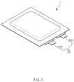
- FIG. 2 is a perspective view of the pouch type secondary battery 1 of FIG. 1 , which is completely manufactured.
- the lithium secondary battery 1 In general, in order to manufacture the lithium secondary battery 1, first, slurry in which an electrode active material, a binder, and a plasticizer are mixed is applied to a positive electrode collector and a negative electrode collector to manufacture a positive electrode and a negative electrode. Then, a separator is laminated on both sides to form an electrode assembly 10. Also, the electrode assembly 10 is accommodated in a battery case, and an electrolyte is injected. Then, sealing is performed.
- the electrode assembly 10 includes an electrode tab 11.
- the electrode tab 11 is connected to each of a positive electrode and a negative electrode of the electrode assembly 10 to protrude to the outside of the electrode assembly 10, thereby providing a path, through which electrons moves, between the inside and outside of the electrode assembly 10.
- the electrode collector of the electrode assembly 10 is constituted by a portion coated with the slurry and a distal end, on which the slurry is not applied, i.e., a non-coating portion.
- the electrode tab 111 may be formed by cutting the non-coating portion or by connecting a separate conductive member to the non-coating portion through ultrasonic welding.
- the electrode tabs 11 may protrude from one side of the electrode assembly 10 in the same direction, but the present invention is not limited thereto.
- the electrode tabs 11 may protrude in directions different from each other.
- the electrode lead 12 is connected to the electrode tab 11 through spot welding. Also, a portion of the electrode lead 12 is surrounded by an insulation part 14.
- the insulation part 14 may be disposed to be limited within a sealing part, at which an upper pouch 131 and a lower pouch 132 are thermally fused, so that the electrode lead 12 is bonded to the battery case 13. Also, electricity generated from the electrode assembly 10 may be prevented from flowing to the battery case 13 through the electrode lead 12, and the sealing of the battery case 13 may be maintained.
- the insulation part 14 may be made of a nonconductor having non-conductivity, which is not electrically conductive.
- the present invention is not limited thereto.
- various members may be used as the insulation part 14 as long as the members are capable of insulating the electrode lead 12.
- the electrode lead 12 may extend in the same direction or extend in directions different from each other according to the formation positions of the positive electrode tab 111 and the negative electrode tab 112.
- the positive electrode lead 121 and the negative electrode lead 122 may be made of materials different from each other. That is, the positive electrode lead 121 may be made of the same material as the positive current collector, i.e., an aluminum (Al) material, and the negative electrode lead 122 may be made of the same material as the negative current collector, i.e., a copper (Cu) material or a copper material coated with nickel (Ni). Also, a portion of the electrode lead 12, which protrudes to the outside of the battery case 13, may be provided as a terminal part and electrically connected to an external terminal.
- the battery case 13 may be a pouch made of a flexible material.
- the case in which the battery case 13 is the pouch will be described.
- th battery case 13 accommodates the electrode assembly 10 so that a portion of the electrode lead 12, i.e., the terminal part is exposed and then is sealed.
- the battery case 13 includes the upper pouch 131 and the lower pouch 132.
- An accommodation space 133 in which the electrode assembly 10 is accommodated may be provided in the lower pouch 132, and upper pouch 131 may cover an upper side of the accommodation space 133 so that the electrode assembly 10 is not separated to the outside of the battery case 13.
- an accommodation space may also be provided in the upper pouch 131 to accommodate the electrode assembly 10 through an upper side of the upper pouch 131.
- the upper pouch 131 and the lower pouch 132 may be separately provided, but the present invention is not limited thereto.
- the upper pouch 131 and the lower pouch 132 may be manufactured through various manners, that is, one side of the upper pouch 131 and one side of the lower pouch 132 may be connected to each other.
- the electrode assembly 10 When the electrode lead 12 is connected to the electrode tab 11 of the electrode assembly 10, and the insulation part 14 is provided on a portion of the electrode lead 12, the electrode assembly 10 may be accommodated in the accommodation space 133 provided in the lower pouch 132, and the upper pouch 131 may cover the upper side of the accommodation space 133. Also, when the electrolyte is injected, and the sealing part provided on an edge of each of the upper pouch 131 and the lower pouch 132 is sealed to manufacture the secondary battery 1 as illustrated in FIG. 2 .
- FIG. 3 is a cross-sectional view of a pouch film 20a for a secondary battery according to a related art.
- a battery case 13 accommodating an electrode assembly 10 is manufactured by elongating a pouch film 20a in which a first polymer layer, a gas barrier layer 21a, and a second polymer layer are sequentially laminated. Also, the polymer layer disposed at the outermost layer of the first and second polymer layers is provided as a surface protection layer 22, and the polymer layer disposed at the innermost layer may be provided as a sealant layer 23.
- the "the first" and “the second” only indicate that two configurations are different from each other and are not intended to fix the name.
- the gas barrier 21a may secure mechanical strength of the battery case 13, block introduction and discharge of gas or moisture outside the secondary battery, and prevent an electrolyte from leaking.
- the gas barrier layer 21a includes a metal.
- aluminum (Al) is mainly used for the gas barrier layer 21a.
- Aluminum may secure the mechanical strength of a predetermined level or more, but be light in weight.
- aluminum may secure complement and heat dissipation for electrochemical properties of the electrode assembly 10 and the electrolyte.
- a metal foil particularly, an Al foil is used for manufacture the gas barrier layer 21a.
- the gas barrier layer 21a is manufactured by using the Al foil, the pouch is limited in flexibility. Thus, when the pouch is bent several times, the pouch may be cut or damaged.
- the gas barrier layer 21 is manufactured by depositing metal particles 210 on the first polymer layer instead of the metal thin film and then sintering the first polymer layer on which the metal particles 210 are deposited.
- a method for manufacturing a pouch film 20 for a secondary battery includes a step of applying an adhesive on one surface of a first polymer layer, a step of depositing metal particles 210 on the applied adhesive, a step of applying heat and a pressure to the deposited metal particles 210 to sinter the metal particles and thereby to form a gas barrier layer 21, and a step of laminating a second polymer layer on one surface of the gas barrier layer 21.
- the first polymer layer is provided as a surface protection layer 22 that is disposed at the outermost layer
- the second polymer layer is provided as a sealant layer 23 that is disposed at the innermost layer
- the first polymer layer may be provided as the sealant layer 23 that is disposed at the innermost layer
- the second polymer layer may be provided as the surface protection layer 22 that is disposed at the outermost layer.
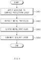
- FIG. 4 is a flowchart illustrating a method for manufacturing a pouch film 20 for a secondary battery according to an embodiment of the present invention.
- FIG. 5 is a cross-sectional view illustrating a process of depositing metal particles 210 on a surface protection layer 22 to manufacture the pouch film 20 for the secondary battery according to an embodiment of the present invention.
- the first polymer layer may be the surface protection layer 22 that is disposed at the outermost layer as illustrated in FIG. 5 .
- the surface protection layer 22 is made of a polymer and disposed at the outermost layer to protect the secondary battery 1 against external friction and collision and also electrically insulates the electrode assembly 10 from the outside.
- the outermost layer represents a direction opposite to a direction in which the electrode assembly 10 is disposed with respect to the gas barrier layer 21, i.e., in an outward direction.
- the surface protection layer 22 may be made of at least one or more materials selected from the group consisting of polyethylene, polypropylene, polycarbonate, polyethylene terephthalate, polyvinyl chloride, acrylic polymer, polyacrylonitrile, polyimide, polyamide, cellulose, aramid, nylon, polyester, polyparaphenylene benzobisoxazole, polyarylate, teflon, and glass fiber. Particularly, a polymer such as a nylon resin or polyethylene terephthalate (PET) having mainly abrasion resistance and heat resistance is used. Also, the surface protection layer 22 may have a single layer structure made of one material or a composite layer structure in which two or more materials are respectively formed as layers.
- the metal particles 210 are made of one or more materials selected from the group consisting of aluminum (Al), iron (Fe), molybdenum (Mo), stainless steel, chromium (Cr), manganese (Mn), and nickel (Ni). Particularly, as descried above, aluminum may secure the mechanical strength of a predetermined level or more, but be light in weight. Thus, aluminum may secure complement and heat dissipation for electrochemical properties of the electrode assembly 10 and the electrolyte. Thus, the metal particles 210 may preferably include aluminum (Al). Also, in order to uniformly deposit the metal particles 210, each of the metal particles 210 may have a diameter of 0.01 ⁇ m to 15 ⁇ m, preferably, 0.01 ⁇ m to 10 ⁇ m.
- the metal particle 210 When the metal particle 210 has a diameter of 15 ⁇ m or more, a pore generated between the metal particles 210 may be too large. In addition, since it is difficult to manufacture the metal particle 20 having a diameter of 0.01 ⁇ m or less, manufacturing costs may increase.
- a binder may be mixed to be deposited together with the metal particles 210.
- the binder may be made of a material selected from the group consisting of polyethylene (PE), polypropylene (PP), stearic acid (SA), polyethylene glycol (PEG), polyacetal (PA), paraffin wax And carnauba wax (CW).
- the method for depositing the metal particles 210 may include various methods such as a rotating electrode method, a rotating disc method, a water atomization method, a gas atomization method, a plasma atomization method, a spark erosion method, and the like. Particularly, when the metal particle 210 has a diameter of 0.01 ⁇ m to 10 ⁇ m as described above, the water atomization method, the water atomization method, the plasma atomization method, or the spark erosion method may be preferably used. However, the present invention is not limited thereto. For example, various deposition methods may be used as long as the metal particles 210 is capable of being deposited on one surface of the first polymer layer.
- the metal particles 210 are directly deposited on the adhesive after the adhesive is applied to one surface of the first polymer layer, i.e., the surface protection layer 22 in FIG. 5 , the embodiment of the present invention is not limited thereto.
- the adhesive may be applied, and then the metal particles 210 may be deposited.
- the separate layer may include other polymer, synthetic rubber, a metal, or the like.
- FIG. 6 is an SEM photograph illustrating a state after the metal particles 210 are deposited in FIG. 5 .
- pores are generated between the deposited metal particles 210 when the metal particles 210 are deposited.
- moisture or an electrolyte may be easily permeated through the pores, and thus, the gas barrier layer 21 may be corroded or damaged.
- a sintering process may be further performed (S403).
- the sintering is a phenomenon in which, when powder or particles are heated at a temperature below the point at which the powder or particles are compressed and melted, the powder or particles adhere to each other while being melted and thus are solidified.
- the method for sintering the metal particles 210 may include various sintering methods such as a normal sintering method, a reactive sintering method, a pressure sintering method, an isostatic pressure sintering method, a gas pressure sintering method, a re-sintering method, an impact compression sintering method, and the like, but is not limited thereto.
- the temperature of the heat and the pressure, which are applied to perform the sintering may vary depending on the material of the metal particles 210, but the adequate sintering temperature is 50°C to200°C, preferably, 100°C to 150°C. Also, the adequate sintering pressure is 50 MPa to 1,000 MPA, preferably, 100 MPa to 500 MPa. If the sintering temperature is less than 50°C, the sintering may not be properly performed. If the sintering temperature exceeds 200°C, the surface protection layer 22 may be damaged. Also, when the pressure is less than 500 MPa, since the pores between the metal particles 210 are not removed, a fractional density may be lowered. When the pressure exceeds 1,000 MPa, the surface protection layer 22 may be damaged.
- FIG. 7 is an SEM photograph illustrating a state after the metal particles 210 are sintered
- FIG. 8 is a cross-sectional view illustrating a state in which the deposited metal particles 210 are sintered to form the gas barrier layer 21.
- the gas barrier layer 21 of the pouch film 20 may include a sintered body.
- FIG. 9 is a cross-sectional view of the pouch film 20 for the secondary battery according to the present invention, which is manufactured by laminating the sealant layer 23 on the gas barrier layer 21 in FIG. 7 .
- the adhesive is applied to one surface of the gas barrier layer 21or one surface of the sealant layer 23, and a second polymer layer is laminated (S404).
- the second polymer layer may be the sealant layer 23 that is disposed at the innermost layer as illustrated in FIG. 9 . Then, the pouch film 20 according to an embodiment of the present invention is completely manufactured.
- the sealant layer 23 is made of a polymer and disposed at the innermost layer to directly contact the electrode assembly 10.
- the pouch type battery case 13 may be manufactured while a portion thereof is elongated to form an accommodation space 133 having a bag shape when a pouch film 20a having the lamination structure as described above is drawn by using punch or the like. Also, when the electrode assembly 10 is accommodated in the accommodation space 133, the electrolyte is injected. Thereafter, when the upper pouch 131 and the lower pouch 132 may contact each other, and thermal compression is applied to the sealing part, the sealant layers may be bonded to each other to seal the battery case 13. Here, since the sealant layer 23 directly contacts the electrode assembly 10, the sealant layer 23 may have to have insulating properties.
- the sealant layer 23 since the sealant layer 23 contacts the electrolyte, the sealant layer 23 may have to have corrosion resistance. Also, since the inside of the battery case 13 is completely sealed to prevent materials from moving between the inside and outside of the battery case 13, high sealability has to be realized. That is, the sealing part on which the sealant layers 23 are bonded to each other has to have superior thermal bonding strength.
- the sealant layer 23 may be made of at least one or more materials selected from the group consisting of polyethylene, polypropylene, polycarbonate, polyethylene terephthalate, polyvinyl chloride, acrylic polymer, polyacrylonitrile, polyimide, polyamide, cellulose, aramid, nylon, polyester, polyparaphenylene benzobisoxazole, polyarylate, teflon, and glass fiber.
- a polyolefin-based resin such as polypropylene (PP) or polyethylene (PE) may be used for the sealant layer 23.
- Polypropylene (PP) is excellent in mechanical properties such as tensile strength, rigidity, surface hardness, abrasion resistance, and heat resistance and chemical properties such as corrosion resistance and thus is mainly used for manufacturing the sealant layer 23.
- the sealant layer 23 may be made of a cated polypropylene or a polypropylene-butylene-ethylene terpolymer.
- the sealant layer 23 may have a single layer structure made of one material or a composite layer structure in which two or more materials are respectively formed as layers.
- the embodiment of the present invention is not limited thereto.
- at least one separate layer may be further laminated on the one surface of the barrier layer 21, and then, the sealant layer 23 may be laminated. That is, the separate layer may be further provided between the surface protection layer 22 and the gas barrier layer 21 or between the gas barrier layer 21 and the sealant layer 23, and thus, the pouch film 20 may include four or more layers.
- the separate layer may include other polymer, synthetic rubber, a metal, or the like.
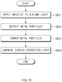
- FIG. 10 is a flowchart illustrating a method for manufacturing a pouch film 20 for a secondary battery according to another embodiment of the present invention.
- metal particles 210 are deposited on one surface of a surface protection layer 22 and then sintered to form a gas barrier layer 21.
- the metal particles 210 are deposited on one surface of the sealant layer 23 but one surface of the surface protection layer 22 and then sintered to manufacture the gas barrier layer 21.
- FIG. 11 is a cross-sectional view illustrating a process of depositing metal particles 210 on a surface protection layer 23 to manufacture the pouch film 20 for the secondary battery according to another embodiment of the present invention.
- the first polymer layer may be a sealant layer 23 that is disposed at the innermost layer as illustrated in FIG. 11 .
- a binder may be mixed to be deposited together with the metal particles 210.
- FIG. 12 is a cross-sectional view illustrating a state in which the deposited metal particles are sintered to form a gas barrier layer 21 in FIG. 11 .
- a process of sintering the deposited metal particles 210 is performed (S803).
- the metal particles 210 are sintered, pores between the metal particles 210 may be removed to allow the particles to be closely attached to each other.
- the gas barrier layer 21 of the pouch film 20 may include a sintered body.
- the adhesive is applied to one surface of the gas barrier layer 21or one surface of a second polymer layer, and then, the second polymer layer is laminated (S804).
- the second polymer layer may be a surface protection layer 22 that is disposed at the outermost layer as illustrated in FIG. 9 .
- the pouch film 20 according to another embodiment of the present invention is completely manufactured.
- the pouch film 20 manufactured through the above-described method according to the present invention includes a first polymer layer; an adhesive layer disposed on one surface of the first polymer layer; a gas barrier layer 21 disposed on the adhesive layer and including a sintered body of metal particles 210; and a second polymer layer laminated on one surface of the gas barrier layer 21. Since specific specifications of the first polymer layer, the adhesive layer, the gas barrier layer 21, and the second polymer layer are the same as described above, their detailed descriptions will be omitted.
- the metal particles 210 are deposited and sintered to manufacture the gas barrier layer.
- the gas barrier layer may be thinner when compared to the of the gas barrier layer of the pouch film according to the related art.
- the gas barrier layer 21 has a thickness of 0.01 ⁇ m to 15 ⁇ m, preferably, 1 ⁇ m to 14 ⁇ m. Also, when the gas barrier layer has a thickness that satisfies the above range, excellent flexibility may be realized.
- the gas barrier layer 21 includes the sintered body that is sintered after depositing the metal particles 210, pores may not exist between the metal particles 210, and since permeability of an electrolyte or moisture is low, a waterproof property and electrolytic resistance are excellent.
- the pouch film 20 according to the present invention has adhesive strength of 3 N/15mm to 4.5 N/15mm, preferably, 3.1 N/15mm to 3.9 N/15mm between the sealant layer 23 and the gas barrier layer 21, which is measured after being impregnated in the electrolyte for 24 hours at a temperature of 85°C.
- the pouch film according to the present invention may have moisture permeability (i.e., water vapor transmission rate (WVTR)) of 7x10 -3 g/m 2 /day to 9x10 -3 g/m 2 /day, preferably, 8x10 -3 g/m 2 /day to 8.5x10 -3 g/m 2 /day, which is measured under conditions of a temperature of 38°C and a relative humidity of 100%.
- WVTR water vapor transmission rate
- An adhesive was applied to one surface of a surface protection layer made of polyethylene terephthalate (PET), and aluminum (Al) metal particles, each of which has a diameter of 0.1 ⁇ m to 10 ⁇ m were deposited by using a plasma atomization method. Thereafter, a temperature of 150°C and a pressure of 200 MPa were maintained, and the metal particles were sintered by using a pressure sintering method to form a gas barrier layer. Here, the formed gas barrier layer was measured to a thickness of 10 ⁇ m. Then, an adhesive was applied on one surface of the gas barrier layer, and a sealant layer made of polypropylene (PP) was laminated to manufacture a pouch film.
- PP polypropylene
- An adhesive was applied to one surface of a surface protection layer made of polyethylene terephthalate (PET), an aluminum foil (Al foil) having a thickness of 15 ⁇ m was laminated on the adhesive on the one side of the surface protection layer, an adhesive was applied on the aluminum thin film, and a sealant layer made of polypropylene (PP) is laminated to manufacture a pouch film having the structure of FIG. 3 .
- a surface protection layer made of polyethylene terephthalate (PET)
- Al foil aluminum foil having a thickness of 15 ⁇ m
- a pouch film was manufactured through the same manner as Manufacturing Example 1, except that the sintering process was not performed after depositing the metal particles.
- the pouch film manufactured as described above has the structure of FIG. 13 .
- a bending test was performed as described below to measure flexibility.
- each of the pouch films manufactured through Manufacturing Example 1 and Comparative Manufacturing Examples 1 and 2 was cut to a size of 15 mm x 150 mm.
- one side of each of the pouch films was fixed to an upper jig of an MIT folding endurance tester, and the other side of each of the pouch films was fixed to a lower fixing jig (a tip has a curvature radius of 0.1 mm and a load of 250 g).
- the pouch films were repeatedly bent at an angle of ⁇ 90° and at the same speed of 175 cpm. After repeating the bending, LED light was irradiated to each of the pouch films to measure the number of times of bending immediately before pinholes are generated.
- Each of the pouch films manufactured through Manufacturing Example 1 and Comparative Manufacturing Examples 1 and 2 was cut to a size of 25 mm x 100 mm. Then, 80 ml of an electrolyte (1 M of lithium salt (LiPF6) and a mixture, in which ethylene carbonate (EC)):ethyl methyl carbonate (EMC):dimethyl carbonate (DMC) are mixed at a ratio of 3:3:4, are melted) and the pouch films were accommodated in a Nalgene bottle having a capacity of 125 ml and then sealed with paraffin. The Nalgene bottle was sealed with an aluminum wrapper and stored at a temperature of 85°C for 24 hours. Then, the pouch films were taken out and rinsed in water, and the water was completely removed.
- LiPF6 lithium salt
- EMC ethyl methyl carbonate
- DMC dimethyl carbonate
- each of the pouch films was cut by a width of 5 mm from both sides thereof to manufacture a sample having a size of 15 mm x 100 mm. Then, a surface protection layer of the sample was sheathed, repeatedly bent, and cut up to a gas barrier layer. Then, the sample was pulled toward both sides to delaminate a portion of the sealant layer so that the portion of the sealant layer is exposed.
- the delaminated sealant layer was fixed to an upper jig of a universal testing machine (UTM), and the remaining portion was attached to a slide glass by using a double-sided tape and then fixed to a lower jig.
- Each of the pouch films manufactured through Manufacturing Example 1 and Comparative Manufacturing Examples 1 and 2 was cut to a size of 108 mm x 108 mm and mounted in a WVRT tester. Then, a dry nitrogen gas which does not contain water vapor was introduced into one surface of the pouch film, and the water vapor was introduced into the other surface of the pouch film. Here, the two spaces into which the gases are respectively introduced were isolated from each other so that the gases introduced into both the surfaces of the pouch film are not mixed with each other. During the experiment, the temperature was set and maintained at 38°C, and the humidity was set and maintained at 100% RH. Also, an amount of water vapor was measured on the above-mentioned surface into which the dried nitrogen gas is introduced by using a humidity sensor for 24 hours.
- the pouch film according to Manufacturing Example 1 was not damaged until the bending test is performed up to 170 times, the pouch film according to Comparative Manufacturing Example 1 was not damaged until the bending test is performed up to 30 times, and the pouch film according to Comparative Manufacturing Example 2 was not damaged until the bending test is performed up to 200 times.
- the pouch film according to Manufacturing Example 1 is much more flexible than that of the pouch film according to Comparative Manufacturing Example 1.
- the bonding strength of the pouch film according to Manufacturing Example 1 was 3.3 N/15 mm
- the bonding strength of the pouch film according to Comparative Manufacturing Example 1 was 6.2 N/15 mm.
- the gas barrier layer was corroded by the electrolytic, and thus, the measurement was impossible.
- the pouch film according to Manufacturing Example 1 is much more electrolyte resistance than that of the pouch film according to Comparative Manufacturing Example 1.
- the pouch film according to Manufacturing Example 1 had a WVTR of 8.06x10 -3 g/m 2 ⁇ day
- the pouch film according to Comparative Manufacturing Example 1 had a WVTR of 9.6x10 -4 g/m 2 ⁇ day
- the pouch film according to Comparative Manufacturing Example 2 had a WVTR of 1.2x10 -2 g/m 2 ⁇ day.
- the pouch film according to Manufacturing Example 1 is much more waterproof property than that of the pouch film according to Comparative Manufacturing Example 1.
- the pouch film according to Manufacturing Example 1 may be improved in waterproof property and electrolyte resistance by sintering the metal particles to reduce the number of gaps between the gas barrier layers.
- the pouch film according to an embodiment of the present invention is superior to the pouch film according to the related art in flexibility, water resistance and electrolyte resistance of the pouch.
Landscapes
- Chemical & Material Sciences (AREA)
- Chemical Kinetics & Catalysis (AREA)
- Electrochemistry (AREA)
- General Chemical & Material Sciences (AREA)
- Engineering & Computer Science (AREA)
- Materials Engineering (AREA)
- Organic Chemistry (AREA)
- Metallurgy (AREA)
- Mechanical Engineering (AREA)
- Inorganic Chemistry (AREA)
- Manufacturing & Machinery (AREA)
- Sealing Battery Cases Or Jackets (AREA)
- Laminated Bodies (AREA)
Abstract
Description
- The present application claims the benefit of the priority of Korean Patent Application No.
10-2018-0004212, filed on January 12, 2018 - The present invention relates to a pouch film and a method for manufacturing the same, and more particularly, to a pouch film, in which a pouch has excellent flexibility, waterproofness, and electrolyte resistance, and a method for manufacturing the same.
- In general, secondary batteries include nickelcadmium batteries, nickel-hydrogen batteries, lithium ion batteries, and lithium ion polymer batteries. Such a secondary battery is being applied to and used in small-sized products such as digital cameras, P-DVDs, MP3Ps, mobile phones, PDAs, portable game devices, power tools, E-bikes, and the like as well as large-sized products requiring high power such as electric vehicles and hybrid vehicles, power storage devices for storing surplus power or renewable energy, and backup power storage devices.
- Such a secondary battery is classified into a pouch type secondary battery and a can type secondary battery according to a material of a case accommodating the electrode assembly. In the pouch type secondary battery, an electrode assembly is accommodated in a pouch made of a flexible polymer material. Also, in the can type secondary battery, an electrode assembly is accommodated in a case made of a metal or plastic material.
- In general, the pouch includes a gas barrier layer, a surface protection layer, and a sealant layer. The gas barrier layer is configured to block introduction and discharge of a gas and includes a metal. Thus, aluminum (Al) foil is mainly used as the gas barrier layer. The surface protection layer is disposed on the outermost layer to protect the electrode assembly against external friction and collision. Thus, a polymer such as a nylon resin, PET, or the like having abrasion resistance and heat resistance is mainly used for the surface protection layer. Also, the sealant layer is disposed on the innermost layer and directly contacts the electrode assembly. Thus, a polymer such as polypropylene (PP) or the like is mainly used for the sealant layer.
- In recent years, as interest in flexible electronic devices increases, studies on flexible secondary batteries is being also actively conducted. However, the pouch of the secondary battery according to the related art has low flexibility. As a result, when the pouch is bent several times, the pouch may be cut or broken. To solve this problem, techniques in which the gas barrier layer is formed by depositing metal particles have been proposed. However, there has been a problem that moisture and other foreign substances are easily permeated because a gap is generated between the deposited metal particles. Particularly, there has been a problem that an electrolyte injected into the pouch is permeated between the metal particles to cause corrosion and damage of the gas barrier layer.
- An object to be solved by the present invention is to provide a pouch film, in which a pouch has excellent flexibility, waterproofness, and electrolyte resistance, and a method for manufacturing the same.
- The objects of the present invention are not limited to the aforementioned object, but other objects not described herein will be clearly understood by those skilled in the art from descriptions below.
- To solve the above problems, a method for a pouch film according to an embodiment of the present invention includes: a step of applying an adhesive on one surface of a first polymer layer; a step of depositing metal particles on the adhesive; a step of applying heat and a pressure to the deposited metal particles to sinter the metal particles and thereby forming a gas barrier layer; and a step of laminating a second polymer layer on one surface of the gas barrier layer.
- Also, the first polymer layer may be a surface protection layer that is an outermost layer of the pouch film, and the second polymer layer may be a sealant layer that is an innermost layer of the pouch film.
- Also, the first polymer layer may be a sealant layer that is an innermost layer of the pouch film, and the second polymer layer may be a surface protection layer that is an outermost layer of the pouch film.
- Also, the metal particles may include aluminum.
- Also, each of the metal particles may have a diameter of 0.01 µm to 15 µm.
- Also, during the step of forming the gas barrier layer, the heat that is applied to the deposited metal particles may have a temperature of 50°C to 200°C.
- Also, during the step of forming the gas barrier layer, the pressure that is applied to the deposited metal particles may be 50 MPa to 1000 MPa.
- Also, the pressure may range of 100 MPa to 500 MPa.
- To solve the above problems, a pouch film includes: a first polymer layer; an adhesive layer disposed on one surface of the first polymer layer; a gas barrier layer disposed on the adhesive layer and including a sintered body of metal particles; and a second polymer layer laminated on one surface of the gas barrier layer.
- Also, the first polymer layer may be a surface protection layer that is an outermost layer of the pouch film, and the second polymer layer may be a sealant layer that is an innermost layer of the pouch film.
- Also, the first polymer layer may be a sealant layer that is an innermost layer of the pouch film, and the second polymer layer may be a surface protection layer that is an outermost layer of the pouch film.
- Also, each of the metal particles of the gas barrier layer may have a diameter of 0.01 µm to 15 µm.
- Also, the first polymer layer or the second polymer layer may be a sealant layer that is an innermost layer of the pouch film, and an adhesive strength between the sealant layer and the gas barrier layer, measured after being impregnated in an electrolyte for 24 hours at a temperature of 85°C, may be 3 N/15mm to 4.5 N/15mm.
- Also, a water vapor transmission rate (WVTR) of the pouch film, measured under a temperature of 38°C and a relative humidity of 100%, may be 7x10⁻³ g/m2/day to 9x10⁻³ g/m2 /day.
- To solve the above problems, a secondary battery according to an embodiment of the present invention include a battery case manufactured using the pouch film.
- Particularities of other embodiments are included in the detailed description and drawings.
- The embodiments of the present invention may have at least the following effects.
- The pouch may be improved in flexibility, waterproofness, and electrolyte resistance.
- Also, the pouch may be manufactured with the thin thickness.
- The effects of the prevent invention are not limited by the aforementioned description, and thus, more varied effects are involved in this specification.
-
-
FIG. 1 is an assembled view of a pouch type secondary battery according to an embodiment of the present invention. -
FIG. 2 is a perspective view of the pouch type secondary battery ofFIG. 1 , which is completely manufactured. -
FIG. 3 is a cross-sectional view of a pouch film for a secondary battery according to a related art. -
FIG. 4 is a flowchart illustrating a method for manufacturing a pouch film for a secondary battery according to an embodiment of the present invention. -
FIG. 5 is a cross-sectional view illustrating a process of depositing metal particles on a surface protection layer to manufacture the pouch film for the secondary battery according to an embodiment of the present invention. -
FIG. 6 is an SEM photograph illustrating a state after the metal particles are deposited inFIG. 5 . -
FIG. 7 is an SEM photograph illustrating a state after the metal particles are sintered. -
FIG. 8 is a cross-sectional view illustrating a state in which the deposited metal particles are sintered to form a gas barrier layer. -
FIG. 9 is a cross-sectional view of a pouch film for the secondary battery according to the present invention, which is manufactured by laminating a sealant layer on the gas barrier layer inFIG. 7 . -
FIG. 10 is a flowchart illustrating a method for manufacturing a pouch film for a secondary battery according to another embodiment of the present invention. -
FIG. 11 is a cross-sectional view illustrating a process of depositing metal particles on a sealant layer to manufacture the pouch film for the secondary battery according to another embodiment of the present invention. -
FIG. 12 is a cross-sectional view illustrating a state in which the deposited metal particles are sintered to form a gas barrier layer inFIG. 11 . -
FIG. 13 is a cross-sectional view of a pouch film manufactured by laminating the sealant layer without sintering the deposited metal particles. - Advantages and features of the present disclosure, and implementation methods thereof will be clarified through following embodiments described with reference to the accompanying drawings. The present invention may, however be embodied in different forms and should not be construed as limited to the embodiments set forth herein. Rather, these embodiments are provided so that this disclosure will be thorough and complete, and will fully convey the scope of the present invention to those skilled in the art. Further, the present invention is only defined by scopes of claims. Like reference numerals refer to like elements throughout.
- Unless terms used in the present invention are defined differently, all terms (including technical and scientific terms) used herein have the same meaning as generally understood by those skilled in the art. Also, unless defined clearly and apparently in the description, the terms as defined in a commonly used dictionary are not ideally or excessively construed as having formal meaning.
- In the following description, the technical terms are used only for explaining a specific exemplary embodiment while not limiting the inventive concept. In this specification, the terms of a singular form may comprise plural forms unless specifically mentioned. The meaning of "comprises" and/or "comprising" does not exclude other components besides a mentioned component.
- Hereinafter, preferred embodiments will be described in detail with reference to the accompanying drawings.
-
FIG. 1 is an assembling view of a pouch typesecondary battery 1 according to an embodiment of the present invention, andFIG. 2 is a perspective view of the pouch typesecondary battery 1 ofFIG. 1 , which is completely manufactured. - In general, in order to manufacture the lithium
secondary battery 1, first, slurry in which an electrode active material, a binder, and a plasticizer are mixed is applied to a positive electrode collector and a negative electrode collector to manufacture a positive electrode and a negative electrode. Then, a separator is laminated on both sides to form anelectrode assembly 10. Also, theelectrode assembly 10 is accommodated in a battery case, and an electrolyte is injected. Then, sealing is performed. - As illustrated in
FIG. 1 , theelectrode assembly 10 includes anelectrode tab 11. Theelectrode tab 11 is connected to each of a positive electrode and a negative electrode of theelectrode assembly 10 to protrude to the outside of theelectrode assembly 10, thereby providing a path, through which electrons moves, between the inside and outside of theelectrode assembly 10. The electrode collector of theelectrode assembly 10 is constituted by a portion coated with the slurry and a distal end, on which the slurry is not applied, i.e., a non-coating portion. Also, theelectrode tab 111 may be formed by cutting the non-coating portion or by connecting a separate conductive member to the non-coating portion through ultrasonic welding. As illustrated inFIG. 1 , theelectrode tabs 11 may protrude from one side of theelectrode assembly 10 in the same direction, but the present invention is not limited thereto. For example, theelectrode tabs 11 may protrude in directions different from each other. - In the
electrode assembly 10, theelectrode lead 12 is connected to theelectrode tab 11 through spot welding. Also, a portion of theelectrode lead 12 is surrounded by aninsulation part 14. Theinsulation part 14 may be disposed to be limited within a sealing part, at which anupper pouch 131 and alower pouch 132 are thermally fused, so that theelectrode lead 12 is bonded to thebattery case 13. Also, electricity generated from theelectrode assembly 10 may be prevented from flowing to thebattery case 13 through theelectrode lead 12, and the sealing of thebattery case 13 may be maintained. Thus, theinsulation part 14 may be made of a nonconductor having non-conductivity, which is not electrically conductive. In general, although an insulation tape which is easily attached to theelectrode lead 12 and has a relatively thin thickness is mainly used as theinsulation part 14, the present invention is not limited thereto. For example, various members may be used as theinsulation part 14 as long as the members are capable of insulating theelectrode lead 12. - The
electrode lead 12 may extend in the same direction or extend in directions different from each other according to the formation positions of thepositive electrode tab 111 and thenegative electrode tab 112. Thepositive electrode lead 121 and thenegative electrode lead 122 may be made of materials different from each other. That is, thepositive electrode lead 121 may be made of the same material as the positive current collector, i.e., an aluminum (Al) material, and thenegative electrode lead 122 may be made of the same material as the negative current collector, i.e., a copper (Cu) material or a copper material coated with nickel (Ni). Also, a portion of theelectrode lead 12, which protrudes to the outside of thebattery case 13, may be provided as a terminal part and electrically connected to an external terminal. - In the pouch type
secondary battery 1 according to an embodiment of the present invention, thebattery case 13 may be a pouch made of a flexible material. Hereinafter, the case in which thebattery case 13 is the pouch will be described. Also,th battery case 13 accommodates theelectrode assembly 10 so that a portion of theelectrode lead 12, i.e., the terminal part is exposed and then is sealed. As illustrated inFIG. 1 , thebattery case 13 includes theupper pouch 131 and thelower pouch 132. Anaccommodation space 133 in which theelectrode assembly 10 is accommodated may be provided in thelower pouch 132, andupper pouch 131 may cover an upper side of theaccommodation space 133 so that theelectrode assembly 10 is not separated to the outside of thebattery case 13. Here, as illustrated inFIG. 1 , an accommodation space may also be provided in theupper pouch 131 to accommodate theelectrode assembly 10 through an upper side of theupper pouch 131. As illustrated inFIG. 1 , theupper pouch 131 and thelower pouch 132 may be separately provided, but the present invention is not limited thereto. For example, theupper pouch 131 and thelower pouch 132 may be manufactured through various manners, that is, one side of theupper pouch 131 and one side of thelower pouch 132 may be connected to each other. - When the
electrode lead 12 is connected to theelectrode tab 11 of theelectrode assembly 10, and theinsulation part 14 is provided on a portion of theelectrode lead 12, theelectrode assembly 10 may be accommodated in theaccommodation space 133 provided in thelower pouch 132, and theupper pouch 131 may cover the upper side of theaccommodation space 133. Also, when the electrolyte is injected, and the sealing part provided on an edge of each of theupper pouch 131 and thelower pouch 132 is sealed to manufacture thesecondary battery 1 as illustrated inFIG. 2 . -
FIG. 3 is a cross-sectional view of apouch film 20a for a secondary battery according to a related art. - In general, as illustrated in
FIG. 3 , abattery case 13 accommodating anelectrode assembly 10 is manufactured by elongating apouch film 20a in which a first polymer layer, agas barrier layer 21a, and a second polymer layer are sequentially laminated. Also, the polymer layer disposed at the outermost layer of the first and second polymer layers is provided as asurface protection layer 22, and the polymer layer disposed at the innermost layer may be provided as asealant layer 23. The "the first" and "the second" only indicate that two configurations are different from each other and are not intended to fix the name. - The
gas barrier 21a may secure mechanical strength of thebattery case 13, block introduction and discharge of gas or moisture outside the secondary battery, and prevent an electrolyte from leaking. In general, thegas barrier layer 21a includes a metal. Particularly, aluminum (Al) is mainly used for thegas barrier layer 21a. Aluminum may secure the mechanical strength of a predetermined level or more, but be light in weight. Thus, aluminum may secure complement and heat dissipation for electrochemical properties of theelectrode assembly 10 and the electrolyte. - In recent years, as interest in flexible electronic devices increases, studies on flexible secondary batteries is being also actively conducted. However, according to the related art, as illustrated in
FIG. 3 , a metal foil, particularly, an Al foil is used for manufacture thegas barrier layer 21a. When thegas barrier layer 21a is manufactured by using the Al foil, the pouch is limited in flexibility. Thus, when the pouch is bent several times, the pouch may be cut or damaged. In addition, it is difficult to manufacture an Al foil having a thickness less than 15 µm with the current technologies, and thus, there is a limit in more improving the flexibility of the pouch. - Thus, according to the present invention, the
gas barrier layer 21 is manufactured by depositingmetal particles 210 on the first polymer layer instead of the metal thin film and then sintering the first polymer layer on which themetal particles 210 are deposited. - Particularly, a method for manufacturing a
pouch film 20 for a secondary battery according to the present invention includes a step of applying an adhesive on one surface of a first polymer layer, a step of depositingmetal particles 210 on the applied adhesive, a step of applying heat and a pressure to the depositedmetal particles 210 to sinter the metal particles and thereby to form agas barrier layer 21, and a step of laminating a second polymer layer on one surface of thegas barrier layer 21. - According to an embodiment of the present invention, the first polymer layer is provided as a
surface protection layer 22 that is disposed at the outermost layer, and the second polymer layer is provided as asealant layer 23 that is disposed at the innermost layer. According to another embodiment of the present invention, the first polymer layer may be provided as thesealant layer 23 that is disposed at the innermost layer, and the second polymer layer may be provided as thesurface protection layer 22 that is disposed at the outermost layer. -
FIG. 4 is a flowchart illustrating a method for manufacturing apouch film 20 for a secondary battery according to an embodiment of the present invention. - Hereinafter, each of the steps illustrated in the flowchart of
FIG. 4 will be described with reference toFIGS. 5 to 9 . -
FIG. 5 is a cross-sectional view illustrating a process of depositingmetal particles 210 on asurface protection layer 22 to manufacture thepouch film 20 for the secondary battery according to an embodiment of the present invention. - First, an adhesive is applied on one surface of the first polymer layer to form an adhesive layer (not shown) (S401), and the
metal particles 210 is deposited on the applied adhesive (S402). According to an embodiment of the present invention, the first polymer layer may be thesurface protection layer 22 that is disposed at the outermost layer as illustrated inFIG. 5 . - The
surface protection layer 22 is made of a polymer and disposed at the outermost layer to protect thesecondary battery 1 against external friction and collision and also electrically insulates theelectrode assembly 10 from the outside. Here, the outermost layer represents a direction opposite to a direction in which theelectrode assembly 10 is disposed with respect to thegas barrier layer 21, i.e., in an outward direction. Thesurface protection layer 22 may be made of at least one or more materials selected from the group consisting of polyethylene, polypropylene, polycarbonate, polyethylene terephthalate, polyvinyl chloride, acrylic polymer, polyacrylonitrile, polyimide, polyamide, cellulose, aramid, nylon, polyester, polyparaphenylene benzobisoxazole, polyarylate, teflon, and glass fiber. Particularly, a polymer such as a nylon resin or polyethylene terephthalate (PET) having mainly abrasion resistance and heat resistance is used. Also, thesurface protection layer 22 may have a single layer structure made of one material or a composite layer structure in which two or more materials are respectively formed as layers. - The
metal particles 210 are made of one or more materials selected from the group consisting of aluminum (Al), iron (Fe), molybdenum (Mo), stainless steel, chromium (Cr), manganese (Mn), and nickel (Ni). Particularly, as descried above, aluminum may secure the mechanical strength of a predetermined level or more, but be light in weight. Thus, aluminum may secure complement and heat dissipation for electrochemical properties of theelectrode assembly 10 and the electrolyte. Thus, themetal particles 210 may preferably include aluminum (Al). Also, in order to uniformly deposit themetal particles 210, each of themetal particles 210 may have a diameter of 0.01 µm to 15 µm, preferably, 0.01 µm to 10 µm. When themetal particle 210 has a diameter of 15 µm or more, a pore generated between themetal particles 210 may be too large. In addition, since it is difficult to manufacture themetal particle 20 having a diameter of 0.01 µm or less, manufacturing costs may increase. - When the
metal particles 210 are deposited, a binder may be mixed to be deposited together with themetal particles 210. The binder may be made of a material selected from the group consisting of polyethylene (PE), polypropylene (PP), stearic acid (SA), polyethylene glycol (PEG), polyacetal (PA), paraffin wax And carnauba wax (CW). - The method for depositing the
metal particles 210 may include various methods such as a rotating electrode method, a rotating disc method, a water atomization method, a gas atomization method, a plasma atomization method, a spark erosion method, and the like. Particularly, when themetal particle 210 has a diameter of 0.01 µm to 10 µm as described above, the water atomization method, the water atomization method, the plasma atomization method, or the spark erosion method may be preferably used. However, the present invention is not limited thereto. For example, various deposition methods may be used as long as themetal particles 210 is capable of being deposited on one surface of the first polymer layer. - Furthermore, although the
metal particles 210 are directly deposited on the adhesive after the adhesive is applied to one surface of the first polymer layer, i.e., thesurface protection layer 22 inFIG. 5 , the embodiment of the present invention is not limited thereto. For example, after at least one separate layer is further laminated on the one surface of theprotection layer 22, the adhesive may be applied, and then themetal particles 210 may be deposited. Here, the separate layer may include other polymer, synthetic rubber, a metal, or the like. -
FIG. 6 is an SEM photograph illustrating a state after themetal particles 210 are deposited inFIG. 5 . - As illustrated in
FIG. 6 , it is seen that pores are generated between the depositedmetal particles 210 when themetal particles 210 are deposited. When the pore are generated between themetal particles 210, moisture or an electrolyte may be easily permeated through the pores, and thus, thegas barrier layer 21 may be corroded or damaged. - To solve this problem, according to an embodiment of the present invention, in addition to the deposition of the
metal particles 210, a sintering process may be further performed (S403). The sintering is a phenomenon in which, when powder or particles are heated at a temperature below the point at which the powder or particles are compressed and melted, the powder or particles adhere to each other while being melted and thus are solidified. The method for sintering themetal particles 210 may include various sintering methods such as a normal sintering method, a reactive sintering method, a pressure sintering method, an isostatic pressure sintering method, a gas pressure sintering method, a re-sintering method, an impact compression sintering method, and the like, but is not limited thereto. - The temperature of the heat and the pressure, which are applied to perform the sintering may vary depending on the material of the
metal particles 210, but the adequate sintering temperature is 50°C to200°C, preferably, 100°C to 150°C. Also, the adequate sintering pressure is 50 MPa to 1,000 MPA, preferably, 100 MPa to 500 MPa. If the sintering temperature is less than 50°C, the sintering may not be properly performed. If the sintering temperature exceeds 200°C, thesurface protection layer 22 may be damaged. Also, when the pressure is less than 500 MPa, since the pores between themetal particles 210 are not removed, a fractional density may be lowered. When the pressure exceeds 1,000 MPa, thesurface protection layer 22 may be damaged. -
FIG. 7 is an SEM photograph illustrating a state after themetal particles 210 are sintered, andFIG. 8 is a cross-sectional view illustrating a state in which the depositedmetal particles 210 are sintered to form thegas barrier layer 21. - As illustrated in
FIG. 7 , when the sintering process is performed, the pores between themetal particles 210 may be removed to allow the particles to be closely attached to each other. Thus, as illustrated inFIG. 8 , thegas barrier layer 21 of thepouch film 20 according to an embodiment of the inventive concept may include a sintered body. -
FIG. 9 is a cross-sectional view of thepouch film 20 for the secondary battery according to the present invention, which is manufactured by laminating thesealant layer 23 on thegas barrier layer 21 inFIG. 7 . - The adhesive is applied to one surface of the gas barrier layer 21or one surface of the
sealant layer 23, and a second polymer layer is laminated (S404). According to an embodiment of the present invention, the second polymer layer may be thesealant layer 23 that is disposed at the innermost layer as illustrated inFIG. 9 . Then, thepouch film 20 according to an embodiment of the present invention is completely manufactured. - The
sealant layer 23 is made of a polymer and disposed at the innermost layer to directly contact theelectrode assembly 10. The pouchtype battery case 13 may be manufactured while a portion thereof is elongated to form anaccommodation space 133 having a bag shape when apouch film 20a having the lamination structure as described above is drawn by using punch or the like. Also, when theelectrode assembly 10 is accommodated in theaccommodation space 133, the electrolyte is injected. Thereafter, when theupper pouch 131 and thelower pouch 132 may contact each other, and thermal compression is applied to the sealing part, the sealant layers may be bonded to each other to seal thebattery case 13. Here, since thesealant layer 23 directly contacts theelectrode assembly 10, thesealant layer 23 may have to have insulating properties. Also, since thesealant layer 23 contacts the electrolyte, thesealant layer 23 may have to have corrosion resistance. Also, since the inside of thebattery case 13 is completely sealed to prevent materials from moving between the inside and outside of thebattery case 13, high sealability has to be realized. That is, the sealing part on which the sealant layers 23 are bonded to each other has to have superior thermal bonding strength. In general, thesealant layer 23 may be made of at least one or more materials selected from the group consisting of polyethylene, polypropylene, polycarbonate, polyethylene terephthalate, polyvinyl chloride, acrylic polymer, polyacrylonitrile, polyimide, polyamide, cellulose, aramid, nylon, polyester, polyparaphenylene benzobisoxazole, polyarylate, teflon, and glass fiber. Particularly, a polyolefin-based resin such as polypropylene (PP) or polyethylene (PE) may be used for thesealant layer 23. Polypropylene (PP) is excellent in mechanical properties such as tensile strength, rigidity, surface hardness, abrasion resistance, and heat resistance and chemical properties such as corrosion resistance and thus is mainly used for manufacturing thesealant layer 23. Furthermore, thesealant layer 23 may be made of a cated polypropylene or a polypropylene-butylene-ethylene terpolymer. Also, thesealant layer 23 may have a single layer structure made of one material or a composite layer structure in which two or more materials are respectively formed as layers. - Although the second polymer layer, i.e., the
sealant layer 23 is directly laminated on the one surface of thegas barrier layer 21 inFIG. 9 , the embodiment of the present invention is not limited thereto. For example, at least one separate layer may be further laminated on the one surface of thebarrier layer 21, and then, thesealant layer 23 may be laminated. That is, the separate layer may be further provided between thesurface protection layer 22 and thegas barrier layer 21 or between thegas barrier layer 21 and thesealant layer 23, and thus, thepouch film 20 may include four or more layers. Here, the separate layer may include other polymer, synthetic rubber, a metal, or the like. -
FIG. 10 is a flowchart illustrating a method for manufacturing apouch film 20 for a secondary battery according to another embodiment of the present invention. - According to an embodiment of the present invention,
metal particles 210 are deposited on one surface of asurface protection layer 22 and then sintered to form agas barrier layer 21. However, in thepouch film 20 for the secondary battery according to another embodiment of the present invention, themetal particles 210 are deposited on one surface of thesealant layer 23 but one surface of thesurface protection layer 22 and then sintered to manufacture thegas barrier layer 21. - Hereinafter, each of the steps illustrated in
FIG. 10 will be described with reference toFIGS. 11 to 13 . -
FIG. 11 is a cross-sectional view illustrating a process of depositingmetal particles 210 on asurface protection layer 23 to manufacture thepouch film 20 for the secondary battery according to another embodiment of the present invention. - In order to manufacture the
pouch film 20, first, an adhesive is applied to one surface of a first polymer layer (S801), andmetal particles 210 are deposited (S802). According to another embodiment of the present invention, the first polymer layer may be asealant layer 23 that is disposed at the innermost layer as illustrated inFIG. 11 . When themetal particles 210 are deposited, a binder may be mixed to be deposited together with themetal particles 210. Hereinafter, duplicated description with those of thepouch film 20 according to the abovementioned embodiment of the present invention will be omitted. However, this is merely for convenience of explanation and is not intended to limit the scope of rights. -
FIG. 12 is a cross-sectional view illustrating a state in which the deposited metal particles are sintered to form agas barrier layer 21 inFIG. 11 . - According to another embodiment of the present invention, a process of sintering the deposited
metal particles 210 is performed (S803). As described above, when themetal particles 210 are sintered, pores between themetal particles 210 may be removed to allow the particles to be closely attached to each other. Thus, thegas barrier layer 21 of thepouch film 20 according to another embodiment of the inventive concept may include a sintered body. - The adhesive is applied to one surface of the gas barrier layer 21or one surface of a second polymer layer, and then, the second polymer layer is laminated (S804). According to another embodiment of the present invention, the second polymer layer may be a
surface protection layer 22 that is disposed at the outermost layer as illustrated inFIG. 9 . Thus, as illustrated inFIG. 9 , thepouch film 20 according to another embodiment of the present invention is completely manufactured. - The
pouch film 20 manufactured through the above-described method according to the present invention includes a first polymer layer; an adhesive layer disposed on one surface of the first polymer layer; agas barrier layer 21 disposed on the adhesive layer and including a sintered body ofmetal particles 210; and a second polymer layer laminated on one surface of thegas barrier layer 21. Since specific specifications of the first polymer layer, the adhesive layer, thegas barrier layer 21, and the second polymer layer are the same as described above, their detailed descriptions will be omitted. - In the
pouch film 20 according to the present invention, themetal particles 210 are deposited and sintered to manufacture the gas barrier layer. Thus, the gas barrier layer may be thinner when compared to the of the gas barrier layer of the pouch film according to the related art. Particularly, according to the present invention, thegas barrier layer 21 has a thickness of 0.01 µm to 15 µm, preferably, 1 µm to 14 µm. Also, when the gas barrier layer has a thickness that satisfies the above range, excellent flexibility may be realized. - Also, in the
pouch film 20 according to the present invention, since thegas barrier layer 21 includes the sintered body that is sintered after depositing themetal particles 210, pores may not exist between themetal particles 210, and since permeability of an electrolyte or moisture is low, a waterproof property and electrolytic resistance are excellent. - Particularly, the
pouch film 20 according to the present invention has adhesive strength of 3 N/15mm to 4.5 N/15mm, preferably, 3.1 N/15mm to 3.9 N/15mm between thesealant layer 23 and thegas barrier layer 21, which is measured after being impregnated in the electrolyte for 24 hours at a temperature of 85°C. - Also, the pouch film according to the present invention may have moisture permeability (i.e., water vapor transmission rate (WVTR)) of 7x10⁻³ g/m2/day to 9x10⁻³ g/m2/day, preferably, 8x10⁻³ g/m2/day to 8.5x10⁻³ g/m2/day, which is measured under conditions of a temperature of 38°C and a relative humidity of 100%.
- An adhesive was applied to one surface of a surface protection layer made of polyethylene terephthalate (PET), and aluminum (Al) metal particles, each of which has a diameter of 0.1 µm to 10 µm were deposited by using a plasma atomization method. Thereafter, a temperature of 150°C and a pressure of 200 MPa were maintained, and the metal particles were sintered by using a pressure sintering method to form a gas barrier layer. Here, the formed gas barrier layer was measured to a thickness of 10 µm. Then, an adhesive was applied on one surface of the gas barrier layer, and a sealant layer made of polypropylene (PP) was laminated to manufacture a pouch film.
- An adhesive was applied to one surface of a surface protection layer made of polyethylene terephthalate (PET), an aluminum foil (Al foil) having a thickness of 15 µm was laminated on the adhesive on the one side of the surface protection layer, an adhesive was applied on the aluminum thin film, and a sealant layer made of polypropylene (PP) is laminated to manufacture a pouch film having the structure of
FIG. 3 . - A pouch film was manufactured through the same manner as Manufacturing Example 1, except that the sintering process was not performed after depositing the metal particles. The pouch film manufactured as described above has the structure of
FIG. 13 . - The physical properties of the pouch films manufactured through Manufacturing Example 1 and Comparative Manufacturing Examples 1 and 2 were measured by following methods. The measurement results were shown in Table 1 below.
- A bending test was performed as described below to measure flexibility. First, each of the pouch films manufactured through Manufacturing Example 1 and Comparative Manufacturing Examples 1 and 2 was cut to a size of 15 mm x 150 mm. Then, one side of each of the pouch films was fixed to an upper jig of an MIT folding endurance tester, and the other side of each of the pouch films was fixed to a lower fixing jig (a tip has a curvature radius of 0.1 mm and a load of 250 g). Also, the pouch films were repeatedly bent at an angle of ± 90° and at the same speed of 175 cpm. After repeating the bending, LED light was irradiated to each of the pouch films to measure the number of times of bending immediately before pinholes are generated.
- Each of the pouch films manufactured through Manufacturing Example 1 and Comparative Manufacturing Examples 1 and 2 was cut to a size of 25 mm x 100 mm. Then, 80 ml of an electrolyte (1 M of lithium salt (LiPF6) and a mixture, in which ethylene carbonate (EC)):ethyl methyl carbonate (EMC):dimethyl carbonate (DMC) are mixed at a ratio of 3:3:4, are melted) and the pouch films were accommodated in a Nalgene bottle having a capacity of 125 ml and then sealed with paraffin. The Nalgene bottle was sealed with an aluminum wrapper and stored at a temperature of 85°C for 24 hours. Then, the pouch films were taken out and rinsed in water, and the water was completely removed. Also, each of the pouch films was cut by a width of 5 mm from both sides thereof to manufacture a sample having a size of 15 mm x 100 mm. Then, a surface protection layer of the sample was sheathed, repeatedly bent, and cut up to a gas barrier layer. Then, the sample was pulled toward both sides to delaminate a portion of the sealant layer so that the portion of the sealant layer is exposed. The delaminated sealant layer was fixed to an upper jig of a universal testing machine (UTM), and the remaining portion was attached to a slide glass by using a double-sided tape and then fixed to a lower jig. Thereafter, force required to delaminate the sealant layer and the gas barrier layer was measured under conditions of a delamination rate of 50 mm/min, a grip gap of 80 mm, and a test distance of 30 nm, and the measured force was evaluated as adhesion strength.
- Each of the pouch films manufactured through Manufacturing Example 1 and Comparative Manufacturing Examples 1 and 2 was cut to a size of 108 mm x 108 mm and mounted in a WVRT tester. Then, a dry nitrogen gas which does not contain water vapor was introduced into one surface of the pouch film, and the water vapor was introduced into the other surface of the pouch film. Here, the two spaces into which the gases are respectively introduced were isolated from each other so that the gases introduced into both the surfaces of the pouch film are not mixed with each other. During the experiment, the temperature was set and maintained at 38°C, and the humidity was set and maintained at 100% RH. Also, an amount of water vapor was measured on the above-mentioned surface into which the dried nitrogen gas is introduced by using a humidity sensor for 24 hours. The amount of water vapor was divided by an area of the surface, and the amount of water vapor per unit area, which passes through the pouch film for 24 hours, was deduced and evaluated by the WVRT.
[Table 1] Manufacturing Example 1 Comparative Manufacturing Example 1 Comparative Manufacturing Example 2 Flexibility [times] 170 30 200 Adhesion Strength [N/15mm] 3.3 6.2 Not measurable WVTR[g/m2·day] 8.06 ×10⁻³ 9.6 ×10⁻⁴ 1.2 ×10⁻² - As shown in Table 1 above, the pouch film according to Manufacturing Example 1 was not damaged until the bending test is performed up to 170 times, the pouch film according to Comparative Manufacturing Example 1 was not damaged until the bending test is performed up to 30 times, and the pouch film according to Comparative Manufacturing Example 2 was not damaged until the bending test is performed up to 200 times. Thus, it is seen that the pouch film according to Manufacturing Example 1 is much more flexible than that of the pouch film according to Comparative Manufacturing Example 1.
- Also, the bonding strength of the pouch film according to Manufacturing Example 1 was 3.3 N/15 mm, and the bonding strength of the pouch film according to Comparative Manufacturing Example 1 was 6.2 N/15 mm. However, in the pouch film according to Comparative Manufacturing Example 2, the gas barrier layer was corroded by the electrolytic, and thus, the measurement was impossible. Thus, it is seen that the pouch film according to Manufacturing Example 1 is much more electrolyte resistance than that of the pouch film according to Comparative Manufacturing Example 1.
- Also, the pouch film according to Manufacturing Example 1 had a WVTR of 8.06x10⁻³ g/m2·day, the pouch film according to Comparative Manufacturing Example 1 had a WVTR of 9.6x10⁻⁴ g/m2·day, and the pouch film according to Comparative Manufacturing Example 2 had a WVTR of 1.2x10⁻² g/m2·day. Thus, it is seen that the pouch film according to Manufacturing Example 1 is much more waterproof property than that of the pouch film according to Comparative Manufacturing Example 1. As described above, when the metal particles are simply deposited without being sintered, too much pores were generated between the metal particles of the pouch film according to Comparative Manufacturing Example 2, and thus, the electrolytic and moisture were easily permeated. However, the pouch film according to Manufacturing Example 1 may be improved in waterproof property and electrolyte resistance by sintering the metal particles to reduce the number of gaps between the gas barrier layers.
- Therefore, it is seen that the pouch film according to an embodiment of the present invention is superior to the pouch film according to the related art in flexibility, water resistance and electrolyte resistance of the pouch.
- Those with ordinary skill in the technical field of the present invention pertains will be understood that the present invention can be carried out in other specific forms without changing the technical idea or essential features. Therefore, the above-disclosed embodiments are to be considered illustrative and not restrictive. Accordingly, the scope of the present invention is defined by the appended claims rather than the foregoing description and the exemplary embodiments described therein. Various modifications made within the meaning of an equivalent of the claims of the invention and within the claims are to be regarded to be in the scope of the present invention.
Claims (14)
- A method for manufacturing a pouch film, the method comprising:applying an adhesive on one surface of a first polymer layer;depositing metal particles on the adhesive;applying heat and a pressure to the deposited metal particles to sinter the metal particles and thereby forming a gas barrier layer; andlaminating a second polymer layer on one surface of the gas barrier layer.
- The method of claim 1, wherein the first polymer layer is a surface protection layer that is an outermost layer of the pouch film, and
the second polymer layer is a sealant layer that is an innermost layer of the pouch film. - The method of claim 1, wherein the first polymer layer is a sealant layer that is an innermost layer of the pouch film, and
the second polymer layer is a surface protection layer that is an outermost layer of the pouch film. - The method of claim 1, wherein the metal particles comprise aluminum.
- The method of claim 1, wherein each of the metal particles has a diameter of 0.01 µm to 15 µm.
- The method of claim 1, wherein, during the forming of the gas barrier layer, the heat that is applied to the deposited metal particles has a temperature of 50°C to 200°C.
- The method of claim 1, wherein, during the forming of the gas barrier layer, the pressure that is applied to the deposited metal particles is 50 MPa to 1000 MPa.
- A pouch film comprising:a first polymer layer;an adhesive layer disposed on one surface of the first polymer layer;a gas barrier layer disposed on the adhesive layer and comprising a sintered body of metal particles; anda second polymer layer laminated on one surface of the gas barrier layer.
- The pouch film of claim 8, wherein the first polymer layer is a surface protection layer that is an outermost layer of the pouch film, and
the second polymer layer is a sealant layer that is an innermost layer of the pouch film. - The pouch film of claim 8, wherein the first polymer layer is a sealant layer that is an innermost layer of the pouch film, and
the second polymer layer is a surface protection layer that is an outermost layer of the pouch film. - The pouch film of claim 8, wherein each of the metal particles of the gas barrier layer has a diameter of 0.01 µm to 15 µm.
- The pouch film of claim 8, wherein the first polymer layer or the second polymer layer is a sealant layer that is an innermost layer of the pouch film, and
an adhesive strength between the sealant layer and the gas barrier layer, measured after being impregnated in an electrolyte for 24 hours at a temperature of 85 °C, is 3 N/15mm to 4.5 N/15mm. - The pouch film of claim 8, wherein a water vapor transmission rate (WVTR) of the pouch film, measured under a temperature of 38°C and a relative humidity of 100%, is 7x10- 3 g/m2/day to 9x10⁻³ g/m2/day.
- A secondary battery comprising a battery case including the pouch film of claim 8.
Priority Applications (1)
| Application Number | Priority Date | Filing Date | Title |
|---|---|---|---|
| PL18899839T PL3595030T3 (en) | 2018-01-12 | 2018-11-16 | Pouch film and method for manufacturing the same |
Applications Claiming Priority (2)
| Application Number | Priority Date | Filing Date | Title |
|---|---|---|---|
| KR1020180004212A KR102255537B1 (en) | 2018-01-12 | 2018-01-12 | The Pouch Film And The Method For Manufacturing Thereof |
| PCT/KR2018/014121 WO2019139245A1 (en) | 2018-01-12 | 2018-11-16 | Pouch film and manufacturing method therefor |
Publications (3)
| Publication Number | Publication Date |
|---|---|
| EP3595030A1 true EP3595030A1 (en) | 2020-01-15 |
| EP3595030A4 EP3595030A4 (en) | 2020-05-06 |
| EP3595030B1 EP3595030B1 (en) | 2021-04-21 |
Family
ID=67219085
Family Applications (1)
| Application Number | Title | Priority Date | Filing Date |
|---|---|---|---|
| EP18899839.7A Active EP3595030B1 (en) | 2018-01-12 | 2018-11-16 | Pouch film and method for manufacturing the same |
Country Status (7)
| Country | Link |
|---|---|
| US (2) | US12107279B2 (en) |
| EP (1) | EP3595030B1 (en) |
| JP (1) | JP7038952B2 (en) |
| KR (1) | KR102255537B1 (en) |
| CN (1) | CN110447121B (en) |
| PL (1) | PL3595030T3 (en) |
| WO (1) | WO2019139245A1 (en) |
Families Citing this family (7)
| Publication number | Priority date | Publication date | Assignee | Title |
|---|---|---|---|---|
| EP4109623A4 (en) | 2020-11-23 | 2024-08-07 | LG Energy Solution, Ltd. | METHOD FOR EVALUATING A BATTERY CELL AND DEVICE FOR EVALUATING A BATTERY CELL |
| KR20240010601A (en) * | 2022-07-14 | 2024-01-24 | 에스케이온 주식회사 | Manufacturing method for pouch, pouch for secondary battery, and pouch-type secondary battery |
| KR102901426B1 (en) | 2023-08-07 | 2025-12-17 | 주식회사 엘지에너지솔루션 | Safety-enhanced pouch-type secondary battery |
| WO2025100839A1 (en) * | 2023-11-08 | 2025-05-15 | 주식회사 엘지에너지솔루션 | Pouch film laminate, pouch-type battery case, and pouch-type secondary battery |
| KR102823202B1 (en) * | 2023-12-05 | 2025-06-20 | 율촌화학 주식회사 | Pouch film, method of manufacturing the same and lithium secondary battery |
| WO2025198318A1 (en) * | 2024-03-18 | 2025-09-25 | 주식회사 엘지에너지솔루션 | Pouch film laminate, pouch-type battery case, and pouch-type secondary battery |
| EP4717452A1 (en) * | 2024-04-18 | 2026-04-01 | Lilium GmbH | Multi-layer assembly and its use as battery enclosure |
Family Cites Families (37)
| Publication number | Priority date | Publication date | Assignee | Title |
|---|---|---|---|---|
| JPS62271371A (en) | 1986-05-16 | 1987-11-25 | Toshiba Battery Co Ltd | Nonaqueous solvent secondary battery |
| JP3652915B2 (en) | 1999-03-19 | 2005-05-25 | 三菱重工業株式会社 | Corrosion-resistant coating forming method on inner surface of cylindrical container and apparatus for forming the same |
| DE10247807A1 (en) * | 2002-10-14 | 2004-04-22 | Tuhh-Technologie-Gmbh | Metal/ceramic composite product with surface strains used in the production of engine parts and hydraulic components comprises a structure composed of several layers with different expansion coefficients |
| JP4442235B2 (en) * | 2004-01-28 | 2010-03-31 | ソニー株式会社 | Negative electrode for secondary battery, secondary battery, and production method thereof |
| JP4699156B2 (en) | 2005-09-29 | 2011-06-08 | 大日本印刷株式会社 | Gas barrier film |
| JP5109418B2 (en) * | 2006-04-26 | 2012-12-26 | 三菱マテリアル株式会社 | ZnO vapor deposition material, method for producing the same, and method for forming ZnO film |
| US7906223B2 (en) * | 2006-09-11 | 2011-03-15 | 3M Innovative Properties Company | Permeable nanoparticle reflector |
| KR100846296B1 (en) | 2006-12-22 | 2008-07-14 | 율촌화학 주식회사 | Cell packaging encapsulant and its manufacturing method |
| JP5515856B2 (en) | 2010-02-26 | 2014-06-11 | 三菱化学株式会社 | Laminated body and packaging material using the same |
| JP5468432B2 (en) * | 2010-03-18 | 2014-04-09 | 山陽特殊製鋼株式会社 | Method for producing thin film on metal powder sintered porous substrate |
| JP5692726B2 (en) | 2010-08-31 | 2015-04-01 | 国立大学法人 鹿児島大学 | Method for producing aluminum thin film |
| WO2013012291A2 (en) * | 2011-07-21 | 2013-01-24 | 한화케미칼 주식회사 | Battery packaging material having heat-dissipating characteristics |
| EP2768062B1 (en) * | 2011-10-13 | 2016-05-18 | LG Chem, Ltd. | Cable-type secondary battery |
| US10614962B2 (en) * | 2011-10-25 | 2020-04-07 | Dai Nippon Printing Co., Ltd. | Packaging material for electrochemical cell |
| JP5840923B2 (en) * | 2011-11-07 | 2016-01-06 | 昭和電工パッケージング株式会社 | Battery exterior body, method for producing battery exterior body, and lithium secondary battery |
| DE102012221753A1 (en) * | 2012-11-28 | 2014-05-28 | Robert Bosch Gmbh | Battery with housing made of plastic laminated fiber composite and battery system and motor vehicle with battery |
| WO2014123164A1 (en) * | 2013-02-06 | 2014-08-14 | 大日本印刷株式会社 | Battery packaging material |
| EP2996170B1 (en) * | 2013-03-25 | 2019-05-08 | Dai Nippon Printing Co., Ltd. | Packaging material for batteries |
| KR101604890B1 (en) * | 2013-04-16 | 2016-03-18 | 경북대학교 산학협력단 | A preparation method of an electroconductive membrane for water purification, a membrane prepared thereby, and a method of water purification by using the membrane |
| KR101470554B1 (en) | 2013-04-29 | 2014-12-10 | 주식회사 엘지화학 | Packaging for a cable-type secondary battery and cable-type secondary battery including the same |
| KR101519742B1 (en) * | 2013-11-28 | 2015-05-12 | 율촌화학 주식회사 | Cell pouch having anti-stress impact and stability, and preparing method thereof |
| JP6240779B2 (en) | 2013-12-12 | 2017-11-29 | ゼネラル・エレクトリック・カンパニイ | Method of depositing an abradable film under a polymer gel |
| FR3023417B1 (en) | 2014-07-01 | 2016-07-15 | I-Ten | COMPLETELY SOLID BATTERY COMPRISING SOLID ELECTROLYTE AND LAYER OF SOLID POLYMERIC MATERIAL |
| US10090556B2 (en) * | 2014-09-04 | 2018-10-02 | Amogreentech Co., Ltd. | Flexible battery, manufacturing method therefor, and auxiliary battery comprising flexible battery |
| CN107078236B (en) | 2014-09-26 | 2021-01-22 | 大日本印刷株式会社 | Packaging materials for batteries |
| JP6549435B2 (en) * | 2015-07-16 | 2019-07-24 | 株式会社キャステム | Method of manufacturing powder pressed compact |
| US10513462B2 (en) * | 2015-09-11 | 2019-12-24 | The Government Of The United States Of America, As Represented By The Secretary Of The Navy | Transparent nanocomposite ceramics built from core/shell nanoparticles |
| JP6859662B2 (en) | 2015-10-28 | 2021-04-14 | 大日本印刷株式会社 | Battery packaging materials, batteries, battery packaging material manufacturing methods, and aluminum alloy foil |
| WO2017073774A1 (en) * | 2015-10-28 | 2017-05-04 | 大日本印刷株式会社 | Battery packaging material, battery, battery packaging material manufacturing method, and aluminum alloy foil |
| JP2017100324A (en) | 2015-11-30 | 2017-06-08 | 東洋アルミニウム株式会社 | Laminated structure and manufacturing method thereof |
| KR101796156B1 (en) | 2016-01-07 | 2017-11-10 | 율촌화학 주식회사 | Cell pouch with high insulation resistance and barrier properties |
| KR102032507B1 (en) | 2016-02-25 | 2019-10-15 | 주식회사 엘지화학 | Pouch case and secondary battery including the same |
| JP6699027B2 (en) | 2016-04-01 | 2020-05-27 | 川研ファインケミカル株式会社 | Heat resistant gas barrier coating |
| KR20170142624A (en) | 2016-06-20 | 2017-12-28 | 주식회사 비티엘첨단소재 | Aluminium pouch film for secondary battery and the manufacturing method of the same |
| KR102442166B1 (en) * | 2016-11-03 | 2022-09-08 | 주식회사 엘지에너지솔루션 | Pouch for flexible secondary battery, flexible secondary battery having the same, and method of producing pouch for flexible secondary battery |
| RU2657894C2 (en) * | 2016-11-09 | 2018-06-18 | Федеральное государственное бюджетное учреждение науки Институт структурной макрокинетики и проблем материаловедения им. А. Г. Мержанова Российской академии наук (ИСМАН) | Method of manufacturing slabs of ceramic and composite materials |
| CN107828979A (en) * | 2017-11-02 | 2018-03-23 | 中国科学院山西煤炭化学研究所 | Copper facing expanded graphite strengthens the preparation method of metal-base composites |
-
2018
- 2018-01-12 KR KR1020180004212A patent/KR102255537B1/en active Active
- 2018-11-16 CN CN201880018847.9A patent/CN110447121B/en active Active
- 2018-11-16 WO PCT/KR2018/014121 patent/WO2019139245A1/en not_active Ceased
- 2018-11-16 US US16/499,557 patent/US12107279B2/en active Active
- 2018-11-16 PL PL18899839T patent/PL3595030T3/en unknown
- 2018-11-16 EP EP18899839.7A patent/EP3595030B1/en active Active
- 2018-11-16 JP JP2019565007A patent/JP7038952B2/en active Active
-
2024
- 2024-08-30 US US18/821,295 patent/US20240421387A1/en active Pending
Also Published As
| Publication number | Publication date |
|---|---|
| EP3595030B1 (en) | 2021-04-21 |
| CN110447121B (en) | 2022-03-22 |
| KR20190086105A (en) | 2019-07-22 |
| KR102255537B1 (en) | 2021-05-25 |
| WO2019139245A1 (en) | 2019-07-18 |
| PL3595030T3 (en) | 2021-10-04 |
| EP3595030A4 (en) | 2020-05-06 |
| CN110447121A (en) | 2019-11-12 |
| US20200044203A1 (en) | 2020-02-06 |
| JP7038952B2 (en) | 2022-03-22 |
| US20240421387A1 (en) | 2024-12-19 |
| US12107279B2 (en) | 2024-10-01 |
| JP2020520834A (en) | 2020-07-16 |
Similar Documents
| Publication | Publication Date | Title |
|---|---|---|
| US20240421387A1 (en) | Pouch Film and Method for Manufacturing the Same | |
| EP4095991B1 (en) | Pouch type battery case and pouch type secondary battery | |
| EP4135105A1 (en) | Pouch film laminate, pouch-type battery case, and pouch-type secondary battery | |
| US11728530B2 (en) | Lithium secondary battery and secondary battery sub module comprising the same | |
| EP3758133B1 (en) | Pouch for secondary battery and pouch type secondary battery | |
| US20240266646A1 (en) | Pouch Film and Secondary Battery | |
| EP4618266A1 (en) | Pouch film laminate and secondary battery | |
| KR102876527B1 (en) | Pouch type secondary battery | |
| KR20250159609A (en) | Pouch type secondary battery | |
| EP4632920A1 (en) | Pouch-type secondary battery | |
| EP4117097A1 (en) | Secondary battery and repair method therefor | |
| KR20190109146A (en) | The Apparatus For Taping The Secondary Battery | |
| KR102928444B1 (en) | Secondary battery | |
| KR102897431B1 (en) | Electrode assembly and secondary battery comprising the same | |
| EP4614689A1 (en) | Pouch-type secondary battery | |
| EP4593170A1 (en) | Pouch film laminate and secondary battery | |
| EP4632888A1 (en) | Pouch film laminate and secondary battery | |
| KR102889705B1 (en) | The Secondary Battery Manufacturing Method | |
| EP4632889A1 (en) | Pouch film laminate and pouch-type secondary battery | |
| EP4614688A1 (en) | Pouch film laminate and secondary battery | |
| CN121729787A (en) | Pouch film laminate, pouch type battery case, and pouch type secondary battery | |
| KR20250165824A (en) | Battery case and secondary battery comprising the same | |
| KR20240142222A (en) | Pouch film, method for manufacturing the same, and pouch type secondary battery comprising the same | |
| KR20250148487A (en) | Pouch type battery case and secondary battery comprising the same |
Legal Events
| Date | Code | Title | Description |
|---|---|---|---|
| STAA | Information on the status of an ep patent application or granted ep patent |
Free format text: STATUS: THE INTERNATIONAL PUBLICATION HAS BEEN MADE |
|
| PUAI | Public reference made under article 153(3) epc to a published international application that has entered the european phase |
Free format text: ORIGINAL CODE: 0009012 |
|
| STAA | Information on the status of an ep patent application or granted ep patent |
Free format text: STATUS: REQUEST FOR EXAMINATION WAS MADE |
|
| 17P | Request for examination filed |
Effective date: 20191010 |
|
| AK | Designated contracting states |
Kind code of ref document: A1 Designated state(s): AL AT BE BG CH CY CZ DE DK EE ES FI FR GB GR HR HU IE IS IT LI LT LU LV MC MK MT NL NO PL PT RO RS SE SI SK SM TR |
|
| AX | Request for extension of the european patent |
Extension state: BA ME |
|
| A4 | Supplementary search report drawn up and despatched |
Effective date: 20200403 |
|
| RIC1 | Information provided on ipc code assigned before grant |
Ipc: H01M 2/10 20060101ALI20200330BHEP Ipc: H01M 2/08 20060101ALI20200330BHEP Ipc: H01M 10/04 20060101ALI20200330BHEP Ipc: B32B 7/12 20060101ALI20200330BHEP Ipc: B32B 27/06 20060101ALI20200330BHEP Ipc: H01M 2/02 20060101AFI20200330BHEP Ipc: C23C 24/08 20060101ALI20200330BHEP |
|
| RIC1 | Information provided on ipc code assigned before grant |
Ipc: H01M 2/10 20060101ALI20201130BHEP Ipc: H01M 10/04 20060101ALI20201130BHEP Ipc: C23C 24/08 20060101ALI20201130BHEP Ipc: B32B 27/06 20060101ALI20201130BHEP Ipc: H01M 2/02 20060101AFI20201130BHEP Ipc: B32B 7/12 20060101ALI20201130BHEP Ipc: C23C 28/02 20060101ALI20201130BHEP Ipc: C23C 26/00 20060101ALI20201130BHEP Ipc: H01M 2/08 20060101ALI20201130BHEP |
|
| GRAP | Despatch of communication of intention to grant a patent |
Free format text: ORIGINAL CODE: EPIDOSNIGR1 |
|
| STAA | Information on the status of an ep patent application or granted ep patent |
Free format text: STATUS: GRANT OF PATENT IS INTENDED |
|
| DAV | Request for validation of the european patent (deleted) | ||
| DAX | Request for extension of the european patent (deleted) | ||
| INTG | Intention to grant announced |
Effective date: 20210114 |
|
| GRAS | Grant fee paid |
Free format text: ORIGINAL CODE: EPIDOSNIGR3 |
|
| GRAA | (expected) grant |
Free format text: ORIGINAL CODE: 0009210 |
|
| STAA | Information on the status of an ep patent application or granted ep patent |
Free format text: STATUS: THE PATENT HAS BEEN GRANTED |
|
| AK | Designated contracting states |
Kind code of ref document: B1 Designated state(s): AL AT BE BG CH CY CZ DE DK EE ES FI FR GB GR HR HU IE IS IT LI LT LU LV MC MK MT NL NO PL PT RO RS SE SI SK SM TR |
|
| REG | Reference to a national code |
Ref country code: GB Ref legal event code: FG4D |
|
| REG | Reference to a national code |
Ref country code: CH Ref legal event code: EP |
|
| REG | Reference to a national code |
Ref country code: DE Ref legal event code: R096 Ref document number: 602018016011 Country of ref document: DE Ref country code: IE Ref legal event code: FG4D |
|
| REG | Reference to a national code |
Ref country code: AT Ref legal event code: REF Ref document number: 1385577 Country of ref document: AT Kind code of ref document: T Effective date: 20210515 |
|
| REG | Reference to a national code |
Ref country code: SE Ref legal event code: TRGR |
|
| REG | Reference to a national code |
Ref country code: LT Ref legal event code: MG9D |
|
| REG | Reference to a national code |
Ref country code: AT Ref legal event code: MK05 Ref document number: 1385577 Country of ref document: AT Kind code of ref document: T Effective date: 20210421 |
|
| REG | Reference to a national code |
Ref country code: NL Ref legal event code: MP Effective date: 20210421 |
|
| PG25 | Lapsed in a contracting state [announced via postgrant information from national office to epo] |
Ref country code: BG Free format text: LAPSE BECAUSE OF FAILURE TO SUBMIT A TRANSLATION OF THE DESCRIPTION OR TO PAY THE FEE WITHIN THE PRESCRIBED TIME-LIMIT Effective date: 20210721 Ref country code: AT Free format text: LAPSE BECAUSE OF FAILURE TO SUBMIT A TRANSLATION OF THE DESCRIPTION OR TO PAY THE FEE WITHIN THE PRESCRIBED TIME-LIMIT Effective date: 20210421 Ref country code: NL Free format text: LAPSE BECAUSE OF FAILURE TO SUBMIT A TRANSLATION OF THE DESCRIPTION OR TO PAY THE FEE WITHIN THE PRESCRIBED TIME-LIMIT Effective date: 20210421 Ref country code: FI Free format text: LAPSE BECAUSE OF FAILURE TO SUBMIT A TRANSLATION OF THE DESCRIPTION OR TO PAY THE FEE WITHIN THE PRESCRIBED TIME-LIMIT Effective date: 20210421 Ref country code: HR Free format text: LAPSE BECAUSE OF FAILURE TO SUBMIT A TRANSLATION OF THE DESCRIPTION OR TO PAY THE FEE WITHIN THE PRESCRIBED TIME-LIMIT Effective date: 20210421 Ref country code: LT Free format text: LAPSE BECAUSE OF FAILURE TO SUBMIT A TRANSLATION OF THE DESCRIPTION OR TO PAY THE FEE WITHIN THE PRESCRIBED TIME-LIMIT Effective date: 20210421 |
|
| PG25 | Lapsed in a contracting state [announced via postgrant information from national office to epo] |
Ref country code: IS Free format text: LAPSE BECAUSE OF FAILURE TO SUBMIT A TRANSLATION OF THE DESCRIPTION OR TO PAY THE FEE WITHIN THE PRESCRIBED TIME-LIMIT Effective date: 20210821 Ref country code: GR Free format text: LAPSE BECAUSE OF FAILURE TO SUBMIT A TRANSLATION OF THE DESCRIPTION OR TO PAY THE FEE WITHIN THE PRESCRIBED TIME-LIMIT Effective date: 20210722 Ref country code: LV Free format text: LAPSE BECAUSE OF FAILURE TO SUBMIT A TRANSLATION OF THE DESCRIPTION OR TO PAY THE FEE WITHIN THE PRESCRIBED TIME-LIMIT Effective date: 20210421 Ref country code: NO Free format text: LAPSE BECAUSE OF FAILURE TO SUBMIT A TRANSLATION OF THE DESCRIPTION OR TO PAY THE FEE WITHIN THE PRESCRIBED TIME-LIMIT Effective date: 20210721 Ref country code: PT Free format text: LAPSE BECAUSE OF FAILURE TO SUBMIT A TRANSLATION OF THE DESCRIPTION OR TO PAY THE FEE WITHIN THE PRESCRIBED TIME-LIMIT Effective date: 20210823 Ref country code: RS Free format text: LAPSE BECAUSE OF FAILURE TO SUBMIT A TRANSLATION OF THE DESCRIPTION OR TO PAY THE FEE WITHIN THE PRESCRIBED TIME-LIMIT Effective date: 20210421 |
|
| RAP2 | Party data changed (patent owner data changed or rights of a patent transferred) |
Owner name: LG ENERGY SOLUTION LTD. |
|
| REG | Reference to a national code |
Ref country code: DE Ref legal event code: R097 Ref document number: 602018016011 Country of ref document: DE |
|
| PG25 | Lapsed in a contracting state [announced via postgrant information from national office to epo] |
Ref country code: DK Free format text: LAPSE BECAUSE OF FAILURE TO SUBMIT A TRANSLATION OF THE DESCRIPTION OR TO PAY THE FEE WITHIN THE PRESCRIBED TIME-LIMIT Effective date: 20210421 Ref country code: CZ Free format text: LAPSE BECAUSE OF FAILURE TO SUBMIT A TRANSLATION OF THE DESCRIPTION OR TO PAY THE FEE WITHIN THE PRESCRIBED TIME-LIMIT Effective date: 20210421 Ref country code: RO Free format text: LAPSE BECAUSE OF FAILURE TO SUBMIT A TRANSLATION OF THE DESCRIPTION OR TO PAY THE FEE WITHIN THE PRESCRIBED TIME-LIMIT Effective date: 20210421 Ref country code: SM Free format text: LAPSE BECAUSE OF FAILURE TO SUBMIT A TRANSLATION OF THE DESCRIPTION OR TO PAY THE FEE WITHIN THE PRESCRIBED TIME-LIMIT Effective date: 20210421 Ref country code: SK Free format text: LAPSE BECAUSE OF FAILURE TO SUBMIT A TRANSLATION OF THE DESCRIPTION OR TO PAY THE FEE WITHIN THE PRESCRIBED TIME-LIMIT Effective date: 20210421 Ref country code: EE Free format text: LAPSE BECAUSE OF FAILURE TO SUBMIT A TRANSLATION OF THE DESCRIPTION OR TO PAY THE FEE WITHIN THE PRESCRIBED TIME-LIMIT Effective date: 20210421 Ref country code: ES Free format text: LAPSE BECAUSE OF FAILURE TO SUBMIT A TRANSLATION OF THE DESCRIPTION OR TO PAY THE FEE WITHIN THE PRESCRIBED TIME-LIMIT Effective date: 20210421 |
|
| PLBE | No opposition filed within time limit |
Free format text: ORIGINAL CODE: 0009261 |
|
| STAA | Information on the status of an ep patent application or granted ep patent |
Free format text: STATUS: NO OPPOSITION FILED WITHIN TIME LIMIT |
|
| 26N | No opposition filed |
Effective date: 20220124 |
|
| RAP4 | Party data changed (patent owner data changed or rights of a patent transferred) |
Owner name: LG ENERGY SOLUTION, LTD. |
|
| PG25 | Lapsed in a contracting state [announced via postgrant information from national office to epo] |
Ref country code: IS Free format text: LAPSE BECAUSE OF FAILURE TO SUBMIT A TRANSLATION OF THE DESCRIPTION OR TO PAY THE FEE WITHIN THE PRESCRIBED TIME-LIMIT Effective date: 20210821 Ref country code: AL Free format text: LAPSE BECAUSE OF FAILURE TO SUBMIT A TRANSLATION OF THE DESCRIPTION OR TO PAY THE FEE WITHIN THE PRESCRIBED TIME-LIMIT Effective date: 20210421 |
|
| PG25 | Lapsed in a contracting state [announced via postgrant information from national office to epo] |
Ref country code: MC Free format text: LAPSE BECAUSE OF FAILURE TO SUBMIT A TRANSLATION OF THE DESCRIPTION OR TO PAY THE FEE WITHIN THE PRESCRIBED TIME-LIMIT Effective date: 20210421 |
|
| REG | Reference to a national code |
Ref country code: CH Ref legal event code: PL |
|
| PG25 | Lapsed in a contracting state [announced via postgrant information from national office to epo] |
Ref country code: LU Free format text: LAPSE BECAUSE OF NON-PAYMENT OF DUE FEES Effective date: 20211116 Ref country code: IT Free format text: LAPSE BECAUSE OF FAILURE TO SUBMIT A TRANSLATION OF THE DESCRIPTION OR TO PAY THE FEE WITHIN THE PRESCRIBED TIME-LIMIT Effective date: 20210421 Ref country code: BE Free format text: LAPSE BECAUSE OF NON-PAYMENT OF DUE FEES Effective date: 20211130 |
|
| REG | Reference to a national code |
Ref country code: BE Ref legal event code: MM Effective date: 20211130 |
|
| PG25 | Lapsed in a contracting state [announced via postgrant information from national office to epo] |
Ref country code: LI Free format text: LAPSE BECAUSE OF NON-PAYMENT OF DUE FEES Effective date: 20211130 Ref country code: CH Free format text: LAPSE BECAUSE OF NON-PAYMENT OF DUE FEES Effective date: 20211130 |
|
| PG25 | Lapsed in a contracting state [announced via postgrant information from national office to epo] |
Ref country code: IE Free format text: LAPSE BECAUSE OF NON-PAYMENT OF DUE FEES Effective date: 20211116 |
|
| REG | Reference to a national code |
Ref country code: DE Ref legal event code: R081 Ref document number: 602018016011 Country of ref document: DE Owner name: LG ENERGY SOLUTION, LTD., KR Free format text: FORMER OWNER: LG CHEM, LTD., SEOUL, KR |
|
| P01 | Opt-out of the competence of the unified patent court (upc) registered |
Effective date: 20230512 |
|
| PG25 | Lapsed in a contracting state [announced via postgrant information from national office to epo] |
Ref country code: CY Free format text: LAPSE BECAUSE OF FAILURE TO SUBMIT A TRANSLATION OF THE DESCRIPTION OR TO PAY THE FEE WITHIN THE PRESCRIBED TIME-LIMIT Effective date: 20210421 |
|
| PG25 | Lapsed in a contracting state [announced via postgrant information from national office to epo] |
Ref country code: HU Free format text: LAPSE BECAUSE OF FAILURE TO SUBMIT A TRANSLATION OF THE DESCRIPTION OR TO PAY THE FEE WITHIN THE PRESCRIBED TIME-LIMIT; INVALID AB INITIO Effective date: 20181116 |
|
| REG | Reference to a national code |
Ref country code: GB Ref legal event code: 732E Free format text: REGISTERED BETWEEN 20230901 AND 20230906 |
|
| PG25 | Lapsed in a contracting state [announced via postgrant information from national office to epo] |
Ref country code: MK Free format text: LAPSE BECAUSE OF FAILURE TO SUBMIT A TRANSLATION OF THE DESCRIPTION OR TO PAY THE FEE WITHIN THE PRESCRIBED TIME-LIMIT Effective date: 20210421 |
|
| PG25 | Lapsed in a contracting state [announced via postgrant information from national office to epo] |
Ref country code: MT Free format text: LAPSE BECAUSE OF FAILURE TO SUBMIT A TRANSLATION OF THE DESCRIPTION OR TO PAY THE FEE WITHIN THE PRESCRIBED TIME-LIMIT Effective date: 20210421 |
|
| PG25 | Lapsed in a contracting state [announced via postgrant information from national office to epo] |
Ref country code: TR Free format text: LAPSE BECAUSE OF FAILURE TO SUBMIT A TRANSLATION OF THE DESCRIPTION OR TO PAY THE FEE WITHIN THE PRESCRIBED TIME-LIMIT Effective date: 20210421 |
|
| PGFP | Annual fee paid to national office [announced via postgrant information from national office to epo] |
Ref country code: DE Payment date: 20251020 Year of fee payment: 8 |
|
| PGFP | Annual fee paid to national office [announced via postgrant information from national office to epo] |
Ref country code: GB Payment date: 20251023 Year of fee payment: 8 |
|
| PGFP | Annual fee paid to national office [announced via postgrant information from national office to epo] |
Ref country code: FR Payment date: 20251021 Year of fee payment: 8 |
|
| PGFP | Annual fee paid to national office [announced via postgrant information from national office to epo] |
Ref country code: SE Payment date: 20251021 Year of fee payment: 8 |
|
| PGFP | Annual fee paid to national office [announced via postgrant information from national office to epo] |
Ref country code: PL Payment date: 20251021 Year of fee payment: 8 |