EP3594918B1 - Rauchmeldersystem - Google Patents
Rauchmeldersystem Download PDFInfo
- Publication number
- EP3594918B1 EP3594918B1 EP19177461.1A EP19177461A EP3594918B1 EP 3594918 B1 EP3594918 B1 EP 3594918B1 EP 19177461 A EP19177461 A EP 19177461A EP 3594918 B1 EP3594918 B1 EP 3594918B1
- Authority
- EP
- European Patent Office
- Prior art keywords
- terminal
- smoke
- sampling circuit
- smoke alarm
- analysis module
- Prior art date
- Legal status (The legal status is an assumption and is not a legal conclusion. Google has not performed a legal analysis and makes no representation as to the accuracy of the status listed.)
- Active
Links
Images


Classifications
-
- G—PHYSICS
- G08—SIGNALLING
- G08B—SIGNALLING OR CALLING SYSTEMS; ORDER TELEGRAPHS; ALARM SYSTEMS
- G08B17/00—Fire alarms; Alarms responsive to explosion
- G08B17/10—Actuation by presence of smoke or gases, e.g. automatic alarm devices for analysing flowing fluid materials by the use of optical means
-
- G—PHYSICS
- G01—MEASURING; TESTING
- G01K—MEASURING TEMPERATURE; MEASURING QUANTITY OF HEAT; THERMALLY-SENSITIVE ELEMENTS NOT OTHERWISE PROVIDED FOR
- G01K3/00—Thermometers giving results other than momentary value of temperature
- G01K3/005—Circuits arrangements for indicating a predetermined temperature
-
- G—PHYSICS
- G01—MEASURING; TESTING
- G01K—MEASURING TEMPERATURE; MEASURING QUANTITY OF HEAT; THERMALLY-SENSITIVE ELEMENTS NOT OTHERWISE PROVIDED FOR
- G01K7/00—Measuring temperature based on the use of electric or magnetic elements directly sensitive to heat ; Power supply therefor, e.g. using thermoelectric elements
- G01K7/16—Measuring temperature based on the use of electric or magnetic elements directly sensitive to heat ; Power supply therefor, e.g. using thermoelectric elements using resistive elements
- G01K7/22—Measuring temperature based on the use of electric or magnetic elements directly sensitive to heat ; Power supply therefor, e.g. using thermoelectric elements using resistive elements the element being a non-linear resistance, e.g. thermistor
- G01K7/24—Measuring temperature based on the use of electric or magnetic elements directly sensitive to heat ; Power supply therefor, e.g. using thermoelectric elements using resistive elements the element being a non-linear resistance, e.g. thermistor in a specially-adapted circuit, e.g. bridge circuit
-
- G—PHYSICS
- G08—SIGNALLING
- G08B—SIGNALLING OR CALLING SYSTEMS; ORDER TELEGRAPHS; ALARM SYSTEMS
- G08B29/00—Checking or monitoring of signalling or alarm systems; Prevention or correction of operating errors, e.g. preventing unauthorised operation
- G08B29/18—Prevention or correction of operating errors
- G08B29/185—Signal analysis techniques for reducing or preventing false alarms or for enhancing the reliability of the system
-
- H—ELECTRICITY
- H03—ELECTRONIC CIRCUITRY
- H03K—PULSE TECHNIQUE
- H03K19/00—Logic circuits, i.e. having at least two inputs acting on one output; Inverting circuits
- H03K19/20—Logic circuits, i.e. having at least two inputs acting on one output; Inverting circuits characterised by logic function, e.g. AND, OR, NOR, NOT circuits
-
- H—ELECTRICITY
- H03—ELECTRONIC CIRCUITRY
- H03M—CODING; DECODING; CODE CONVERSION IN GENERAL
- H03M1/00—Analogue/digital conversion; Digital/analogue conversion
- H03M1/12—Analogue/digital converters
- H03M1/124—Sampling or signal conditioning arrangements specially adapted for A/D converters
Definitions
- the present disclosure relates to smoke alarm technologies, especially a smoke alarm system.
- a method of training a classifier for a smoke detector comprises inputting sensor data from a plurality of tests into a processor.
- the sensor data is processed to generate derived signal data corresponding to the test data for respective tests.
- the derived signal data is assigned into categories comprising at least one fire group and at least one non-fire group.
- Linear discriminant analysis (LDA) training is performed by the processor.
- the derived signal data and the assigned categories for the derived signal data are inputs to the LDA training.
- the output of the LDA training is stored in a computer readable medium, such as in a smoke detector that uses LDA to determine, based on the training, whether present conditions indicate the existence of a fire.
- US5818326 A discloses an early fire detection using temperature and smoke sensing.
- a fire detection system cross correlates the responses of a temperature and smoke sensing units to achieve early-detection characteristics.
- the system also performs threshold-type detection on the smoke obscuration, temperature, and rate of temperature rise. If any of the thresholds are surpassed, the same alarm condition will be set. As a result, the detection characteristics of the resulting detector can be no worse than the conventional threshold-only systems.
- the system advantageously, however, provides for the early detection of fires that satisfy the cross correlation characteristics. Thus, it achieves the best performance characteristics of both approaches.
- the present disclosure is at least directed to provide a smoke alarm system, which can avoid a false alarm because of oversensitivity of smoke alarms, so as to avoid waste of manpower and material resources as much as possible.
- an arrangement of high sensitiveness of a smoke alarm is advantageous for avoiding missing any possible fires, but results in some problems.
- an emergent firefighting shall be prepared to take immediately, causing significant consumption of manpower and material resources.
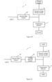
- an embodiment of the present disclosure relates to a smoke alarm system, as shown in Figure 1 , including a smoke alarm 1, a temperature detector 2, a first sampling circuit 3, a second sampling circuit 4, and an analysis module 5.
- a first terminal of the first sampling circuit 3 is connected to the smoke alarm 1, and a second terminal of the first sampling circuit 3 is connected to a first input terminal 51 of the analysis module 5; the first sampling circuit is used for sampling from the smoke alarm 2 to obtain a smoke sample value ADC1 which is then output to the analysis module 5.
- a first terminal of the second sampling circuit 4 is connected to the temperature detector 2, and a second terminal of the second sampling circuit 4 is connected to a second input terminal 52 of the analysis module 5; the second sampling circuit 4 is used for sampling from the temperature detector 2 to obtain a temperature sample value ADC2 which is then output to the analysis module 5.
- the analysis module 5 is used for determining whether a smoke alarm signal is generated in accordance with the smoke sample value ADC1 and the temperature sample value ADC2.
- the temperature detector may be a temperature sensor.
- the first sampling circuit 3 samples from the smoke alarm 1 to obtain a smoke sample value ADC1 which is then output to the analysis module 5; the second sampling circuit 4 samples from the temperature detector 2 to obtain a temperature sample value ADC2 which is then output to the analysis module 5. That is, the smoke detection ADC1 and the temperature detection ADC2 are combined to determine whether a smoke alarm signal is generated, so as to avoid a false alarm because of oversensitivity of a smoke alarm, so as to avoid waste of manpower and material resources as much as possible.
- the first sampling circuit 3 includes a first voltage divider branch 31 and a first filter branch 32.
- a first terminal of the first voltage divider branch 31 is connected to a first terminal of the smoke alarm 1
- a first terminal of the first filter branch 32 is connected to the first terminal of the first voltage divider branch 31, and a second terminal of the first filter branch 32 is used to output the smoke sample value ADC1.
- Either a second terminal of the first voltage divider branch 31 or, in an unclaimed alternative, a second terminal of the smoke alarm 1 serves as a power supply terminal connected to a voltage source VDD, while the other serves as a ground terminal connected to ground GND.
- the second terminal of the first voltage divider branch 31 serves as the power supply terminal connected to the voltage source VDD, while the second terminal of the smoke alarm 1 serves as the ground terminal connected to the ground GND.
- an excitation voltage is applied to the smoke alarm 1 via the first voltage divider branch 31; in other words, the excitation voltage is not directly applied to the smoke alarm 1, thereby avoiding the following problem: short circuit because of a worn connecting line, leading to an abnormal power supply to a printed circuit board, and further affecting sampling.
- the smoke alarm 1 and the first sampling circuit 3 form a smoke detecting module for detecting smoke concentration.
- the smoke alarm 1 is equivalent to a switch that is in a turn-off state, the branch where the first voltage divider branch 31 and the smoke alarm 1 locate are in an OFF state, and the smoke sample value ADC1 output by the second terminal of the first filter branch 32 is at a low level.
- the smoke alarm 1 When the smoke concentration detected by the smoke alarm 1 reaches the preset concentration threshold, the smoke alarm 1 is equivalent to a switch that is in a turn-on state, the branch where the first voltage divider branch 31 and the smoke alarm 1 locate are in an ON state, and the smoke sample value ADC 1 output by the second terminal of the first filter branch 32 is at a high level.
- the smoke sample value ADC1 at a low level indicates that the smoke concentration has not reached the preset concentration threshold
- the smoke sample value ADC1 at a high level indicates that the smoke concentration has reached the preset concentration threshold
- the smoke alarm 1 is equivalent to a switch that is in a turn-on state when the smoke concentration has not reached the preset concentration threshold
- the smoke alarm 1 is equivalent to a switch that is in a turn-off state when the smoke concentration has reached the preset concentration threshold.
- the smoke sample value ADC1 at a high level indicates that the smoke concentration has not reached the preset concentration threshold
- the smoke sample value ADC1 at a low level indicates that the smoke concentration has reached the preset concentration threshold.
- the second sampling circuit 4 comprises a second voltage divider branch 41 and a second filter branch 42.
- a first terminal of the second voltage divider branch 41 is connected to the first terminal of the temperature detector 2
- the first terminal of the second filter branch 42 is connected to the first terminal of the second voltage divider branch 41
- a second terminal of the second filter branch 42 is used to output the temperature sample value ADC2.
- Either a second terminal of the second voltage divider branch 41 or, in an unclaimed alternative a second terminal of the temperature detector 2, serves as a power supply terminal connected to a voltage source VDD, while the other is a ground terminal connected to the ground GND.
- the second terminal of the second voltage divider branch 41 serves as the power supply terminal connected to the voltage source VDD, while the second terminal of the temperature detector 2 is the ground terminal connected to the ground GND.
- the second sampling circuit 4 further includes a voltage follower branch 43 via which the second voltage divider branch 41 is connected to the second filter branch 42.
- the added voltage follower branch 43 can enhance stability of detection signals.
- the temperature detector 2 and the second sampling circuit 3 form a temperature detecting module for detecting ambient temperature.
- the specific type of the temperature detector 2 is not limited and may be any device capable of detecting ambient temperature.
- the temperature detector 2 may be a positive temperature coefficient thermistor whose resistance value increases as temperature rises.
- the resistance value of the thermistor also changes, so that voltage values at both terminals of the temperature detector 2 change, thereby the temperature sample value ADC2 output by the second terminal of the second filter branch 42 changes. That is, the temperature sample value ADC2 reflects the ambient temperature.
- the smoke alarm system may be applied to an energy storage system, and may be used for performing smoke alarm for an electric cabinet in the energy storage system.
- the smoke alarm 1 may be configured at the top of the electric cabinet, and the temperature detector 2 may be configured at any place such as the top, the interior, or an air outlet of the electric cabinet.
- the first sampling circuit 3, the second sampling circuit 4, and the analysis module 5 may be integrated on one printed circuit board which is configured inside the electric cabinet; the first sampling circuit 3 is electrically connected to the smoke alarm 1 via a wire, and the second sampling circuit 4 is electrically connected to the temperature detector 2 via a wire.
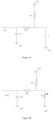
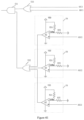
- FIG 3A is a schematic circuit diagram showing a connection between the first sampling circuit and the smoke alarm of the smoke alarm system.
- the smoke alarm 1 includes a smoke detector (not shown) and a switch S.
- the switch S is controlled to be ON so that the circuit is turned on.
- the switch S is used to exemplarily show the connection relationship between the smoke alarm 1 and the first sampling circuit 3.
- figure 3B is a schematic circuit diagram showing a connection between the second sampling circuit and the temperature detector of the smoke alarm system.
- the temperature detector 2 is described by taking a thermistor Rr as an example.
- the second voltage divider branch 41 is a voltage divider resistor R21.
- a first terminal of the voltage divider resistor R21 is connected to a first terminal of the thermistor Rr.
- a second terminal of the voltage divider resistor R21 is connected to the voltage source VDD.
- a second terminal of the thermistor Rr is connected to the ground GND.
- the first sampling circuit 3 may further include a voltage follower branch via which the first voltage divider branch 31 is connected to the first filter branch 32.
- the specific structure of the voltage follower branch in the first sampling circuit 3 may be or not be the same as the specific voltage follower branch 43 in the second sampling circuit 4, which is not limited herein.
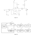
- the analysis module 5 includes a logic gate circuit 53 and a comparator circuit 54; the second terminal of the first sampling circuit 3 is connected to a first input terminal of the logic gate circuit 53; the comparator circuits 54 and the second sampling circuits 4 are equal in number and are in one-to-one correspondence, the second terminal of each of the second sampling circuits 4 is connected to an input terminal of one of the comparator circuits 54, and an output terminal of each of the comparator circuits 54 is connected to a second input terminal of the logic gate circuit 53.
- the first input terminal of the logic gate circuit 53 forms the first input terminal 51 of the analysis module 5, and an input terminal of the comparator circuit 54 forms the second input terminal 52 of the analysis module 5.
- Figure 4A only shows a case where the analysis module 5 includes one comparator circuit when there is one temperature detector 2.
- figure 4B is a schematic circuit diagram of the analysis module 5 when there is one temperature detector 2.
- the logic gate circuit 53 is an AND gate 531.
- the second terminal of the first sampling circuit is connected to a first input terminal of the AND gate 531 to output the smoke sample value ADC1 to the AND gate 531.
- the second terminal of the second sampling circuit is connected to the input terminal of the comparator circuit 54 so as to output the temperature sample value ADC2 to the comparator circuit 54.
- the output terminal of the comparator circuit 54 is connected to a second input terminal of the AND gate 531.
- the comparator circuit 54 includes a comparator A2, a resistor R24, and a resistor R25.
- a non-inverting input terminal of the comparator A2 forms the input terminal of the comparator circuit 54, that is, the non-inverting input terminal of the comparator A2 is connected to the second terminal of the second sampling circuit 4 to receive the temperature sample value ADC2.
- An inverting input terminal of the comparator A2 is connected to the voltage source VDD via the resistor R24 and connected to the ground GND via the resistor R25.
- the voltage source VDD, the resistor R24 and the resistor R25 provide a reference voltage Vrfe to the inverting input terminal of the comparator A2.
- the resistance values of the resistors R24 and R25 may be set as needed, so that the reference voltage Vrfe meets design requirements.
- the comparator A2 receives the temperature sample value ADC2 output by the second sampling circuit 4, compares the temperature sample value ADC2 with the reference voltage Vrfe to output a comparison result.
- the comparator A2 outputs a high level voltage if the temperature sample value ADC2 is higher than the reference voltage Vrfe, but a low level voltage otherwise.
- the thermistor Rr has a positive temperature coefficient, that is, the higher the temperature is, the larger the resistance value of the thermistor Rr is, and the larger the temperature sample value ADC2 is.
- the value of the reference voltage Vrfe can be set as the temperature sample value ADC2 when the ambient temperature has just reached the preset temperature threshold. Therefore, when the ambient temperature has not reached the preset temperature threshold, the temperature sample value ADC2 is smaller than the reference voltage Vrfe, and the comparator A2 outputs a low level voltage. When the ambient temperature exceeds the preset temperature threshold, the temperature sample value ADC2 is greater than the reference voltage Vrfe, and the comparator A2 outputs a high level voltage to the second input terminal of the AND gate 531.
- the first sampling circuit 3 outputs a high-level smoke sample value ADC1 to the first input terminal of the AND gate 531 when the smoke concentration detected by the smoke alarm 1 has reached the preset concentration threshold, and the comparator A2 outputs a high level voltage to the second input terminal of the AND gate 531 when the ambient temperature exceeds the preset temperature threshold.
- An output terminal of the AND gate 531 outputs a high level voltage indicating a smoke alarm signal when the first input terminal and the second input terminal of the AND gate 531 both receive a high level voltage.
- the circuit structure of the above described analysis module 5 results in no output of a smoke alarm signal unless when the smoke alarm detects that the smoke concentration has reached the preset concentration threshold and that the temperature detector detects that the ambient temperature has reached the preset temperature threshold, thereby avoiding a false alarm caused by oversensitivity of a smoke alarm, and avoiding waste of manpower and material resources as much as possible.
- the thermistor Rr when the thermistor Rr has a negative temperature coefficient, it may be configured that the inverting input terminal of the comparator A2 is used to receive the temperature sample value ADC2, and the non-inverting input terminal of the comparator A2 is used to input the reference voltage Vrfe.
- the temperature sample value ADC2 is greater than the reference voltage Vrfe when the ambient temperature has not reached the preset temperature threshold, and the comparator A2 outputs a low level voltage.
- the temperature sample value ADC2 is smaller than the reference voltage Vrfe when the ambient temperature exceeds the preset temperature threshold, and the output terminal of the comparator A2 outputs a high level voltage. In this way, the output terminal of the AND gate 531 does not output a high level voltage indicating a smoke alarm signal, unless the smoke alarm 1 detects that the smoke concentration has reached the preset concentration threshold and that the ambient temperature has exceeded the preset temperature threshold.
- the embodiment does not impose any limitation to the specific circuit design of the comparator circuit 54 or how the comparator circuit 54 is connected to the second sampling circuit, and skilled persons in the art may design according to practical needs.
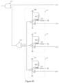
- figure 4C is a schematic circuit diagram of the analysis module 5 when there are a plurality of temperature detectors 2 in the smoke alarm system.
- the logic gate circuit 53 includes the AND gate 531 and the OR gate 532.
- Figure 4C shows a case where there are three comparator circuits when there are three temperature detectors 2, but does not impose any limitation to the number of the temperature detectors 2 (the number of the comparator circuits 54).
- each comparator circuit 54 is connected to an input terminal of the OR gate 532
- an output terminal of the OR gate 532 is connected to the second input terminal of the AND gate 531.
- the specific circuit structure of each comparator circuit 54 is the same as that in Figure 4B , which will not be repeated here.
- the OR gate 532 will output a high level voltage as long as the ambient temperature detected by one of the temperature detectors 2 is greater than the preset temperature threshold.
- figure 4D is a schematic circuit diagram of the analysis module according to an unclaimed embodiment where there are a plurality of first filter branches in the smoke alarm system.
- the logic gate circuit 53 includes the AND gate 531 and the OR gate 533.
- two first filter branches 32 are taken as an example for description.
- each first filter branch 32 is connected to an input terminal of the OR gate 533 to output the smoke sample value ADC1
- the output terminal of the OR gate 533 is connected to the first input terminal of the AND gate 531.
- the second terminal of the second sampling circuit 4 is connected to the input terminal of the comparator circuit 54 to output the temperature sample value ADC2, the output terminal of the comparator circuit 54 is connected to the second input terminal of the AND gate 531.
- figure 4E is a schematic circuit diagram of the analysis module according to an unclaimed example when there are a plurality of first filter branches and temperature detectors in the smoke alarm system.
- the logic gate circuit 53 includes the AND gate 531 and two OR gates.
- the two OR gates are denoted as a first OR gate 533 and a second OR gate 532, respectively.
- two first filter branches 32 are taken as an example for description.
- each first filter branch 32 is connected to one input terminal of the first OR gate 533 to output the smoke sample value ADC1, and an output terminal of the first OR gate 533 is connected to the first input terminal of the AND gate 531.
- the second terminal of each second sampling circuit 4 is connected to the input terminal of one comparator circuit 54 to output the temperature sample value ADC2.
- the output terminal of each comparator circuit 54 is connected to the input terminal of the second OR gate 532.
- the output terminal of the second OR gate 532 is connected to the second input terminal of the AND gate 531.
- the analysis module 5 may be a micro control unit MCU. That is, the MCU may determine whether generate a smoke alarm signal is generated according to the smoke sample value ADC1 and the temperature sample value ADC2.
- the analysis module 5 may be a programmable chip, which may receive the ADC sample values, compare the ADC sample values with corresponding preset values in software, and determine whether a smoke alarm signal is generated.
- figure 5 is a block schematic diagram when there are a plurality of temperature detectors in the smoke alarm system.
- the second sampling circuits 4 and the temperature detectors 2 are equal in number and are in one-to-one correspondence; the second input terminals 52 of the analysis module 5 and the second sampling circuits are equal in number and are in one-to-one correspondence.
- Each temperature detector 2 is connected to a second input terminal 52 of the analysis module 5 via a second sampling circuit 4.
- the three temperature detectors 2 may be respectively configured on the top, the interior, and the outlet of the electric cabinet. It shall be noted that this embodiment does not impose any limitation to the specific number and positions of the temperature detectors 2.
- Figure 5 is merely an exemplary description, and skilled persons in the art may set the number and positions of the temperature detectors 2 according to practical conditions.
- thermosensors 2 which are placed at different positions of the electric cabinet, so that ambient temperatures at different positions of the electric cabinet may be detected, making judgments more accurate.
- the first sampling circuit 3 may include one first filter branch 32, or, in an unclaimed example, the first sampling circuit 3 may include at least two first filter branches 32.
- FIG. 6 is a block schematic diagram of an unclaimed example where there are a plurality of first filter branches in the smoke alarm system.
- the first input terminals 51 of the analysis module 5 and the first filter branches 32 are equal in number and are in one-to-one correspondence.
- the first terminal of each first filter branch 32 is connected to the first terminal of the first voltage divider branch 31, and the second terminal of each first filter branch 32 is connected to one first input terminal 51 of the analysis module 5.
- this embodiment does not impose limitation to the specific number of the first filter branches 32, and Figure 6 is merely an exemplary description, and skilled persons in the art may set the number of the first filter branches 32 according to practical conditions.
- the first sampling circuit 3, the second sampling circuit 4 and the analysis module 5 are integrated on a printed circuit board.
- the first sampling circuit 3 only has one first sampling circuit 3 and one first filter branch 32, so another first filter branch 32, second sampling circuit 4 and analysis module 5 may be integrated on one printed circuit board.
- the first terminal of the first filter branch 32 integrated on the printed circuit board is electrically connected to the first terminal of the sampling circuit 31 in the smoke alarm device. That is, if the number of the first filter branches 32 set is N, N-1 first filter branches 32 may be integrated on one printed circuit board.
- At least two first filter branches are designed to output at least two smoke sample values. That is, a design of multi-channel sampling of smoke concentration is used to replace a design of single-channel sampling in the existing technologies, which can avoid false alarm due to error caused by single sampling.
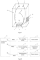
- figure 7 is a structural schematic diagram of the smoke alarm system applied to the electric cabinet 10 in the energy storage system.
- the smoke alarm 1 is configured on a top of the electric cabinet 10, and there are three temperature sensors 2, a first temperature sensor 2 is configured inside of the electric cabinet 10, a second temperature sensor 2 is configured on the top of the electric cabinet 10 and a third temperature sensor 2 is configured at an air outlet of the electric cabinet 10.
- the first sampling circuit 3, the second sampling circuit 4 and the analysis module 5 are integrated on one printed circuit board 30 configured inside the electric cabinet 10.
- the first sampling circuit 3 is electrically connected to the smoke alarm 1 via a wire
- the second sampling circuit 4 is electrically connected to the three temperature sensor 2 via wires respectively
- the analysis module 5 is further electrically connected to the first sampling circuit 3 and the second sampling circuit 4 via wires respectively.
- the connection lines in Figure 7 are merely used for schematically illustrate the electrical connection relationships among the smoke alarm 1, temperature sensors and the sampling circuits and the like, rather than an actual circuit arrangement in the electric cabinet.
- the smoke alarm system may further includes a flame detector, as shown in Figure 8 , including a smoke alarm 1, a temperature detector 2, a flame detector 6, a first sampling circuit 3, a second sampling circuit 4, a third sampling circuit 7, and an analysis module 5.
- a first terminal of the first sampling circuit 3 is connected to the smoke alarm 1, and a second terminal of the first sampling circuit 3 is connected to a first input terminal 51 of the analysis module 5; the first sampling circuit is used for sampling from the smoke alarm 2 to obtain a smoke sample value ADC1 which is then output to the analysis module 5.
- a first terminal of the second sampling circuit 4 is connected to the temperature detector 2, and a second terminal of the second sampling circuit 4 is connected to a second input terminal 52 of the analysis module 5; the second sampling circuit 4 is used for sampling from the temperature detector 2 to obtain a temperature sample value ADC2 which is then output to the analysis module 5.
- a first terminal of the third sampling circuit 7 is connected to the flame detector 6, and a second terminal of the third sampling circuit 7 is connected to a third input terminal 55 of the analysis module 5; the third sampling circuit 7 is used for sampling from the flame detector 6 to obtain a flame sample value ADC3 which is then output to the analysis module 5.
- the analysis module 5 is used for determining whether a smoke alarm signal is generated in accordance with the smoke sample value ADC1, the temperature sample value ADC2 and the flame sample value ADC3.
- the temperature detector may be a temperature sensor
- the flame detector may be a flame sensor.
- the first sampling circuit 3 samples from the smoke alarm 1 to obtain a smoke sample value ADC1 which is then output to the analysis module 5; the second sampling circuit 4 samples from the temperature detector 2 to obtain a temperature sample value ADC2 which is then output to the analysis module 5; the third sampling circuit 7 samples from the flame detector 6 to obtain a flame sample value ADC3 which is then output to the analysis module 5. That is, the smoke detection ADC1, the temperature detection ADC2 and the flame sample value ADC3 are combined to determine whether a smoke alarm signal is generated, which further increase the recognition accuracy of the smoke alarm system, so as to avoid a false alarm because of oversensitivity of a smoke alarm, so as to avoid waste of manpower and material resources as much as possible.
- the flame detector 6 and the third sampling circuit 7 form a flame detecting module for detecting flame.
- the flame sample value ADC3 output by the third sampling circuit 7 is at a low level (or high level); when there is no flame detected by the flame detector 6, the flame sample value ADC3 output by third sampling circuit 7 is at a high level (or low level). That is, the flame sample value ADC3 reflects whether there is a flame in the environment.
- the flame detector 6 may include a flame detecting unit and a switch.
- the switch When the flame detecting unit detects that there is a flame in the environment, the switch is controlled to be ON so that the circuit is turned on.
- the switch is used to exemplarily show the connection relationship between the flame detector and the third sampling circuit, but the actual structure of the flame detector is not limited in any way.
- the flame detector may be configured inside the electric cabinet, the printed circuit board may be further provided with the third sampling circuit, and the third sampling circuit is electrically connected to the flame detector by a wire.
- the flame detector may be replaced by a second smoke alarm, which can further improve the accuracy of smoke detection.
- an operator may easily maintain or replace the flame detector and the smoke alarm, which helps to improve flexibility of the configuration and schedule of the smoke alarm system.
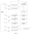
- figure 9 is a block schematic diagram of an unclaimed example where there are a plurality of third filter branches in the third sampling circuit.
- the third input terminals 55 of the analysis module 5 and the third filter branches 71 are equal in number and are in one-to-one correspondence.
- the first terminal of each third filter branch 71 is connected to the flame detector 6, and the second terminal of each third filter branch 71 is connected to one third input terminal 55 of the analysis module 5.
- at least two third filter branches are designed to output at least two flame sample values. That is, a design of multi-channel sampling of burning situation of the flame is used to replace a design of single-channel sampling in the existing technologies, which can avoid false alarm due to error caused by single sampling.
- the logic gate circuit 53 may further includes a further OR gate connecting to the plurality of third filter branches.
- a further OR gate connecting to the plurality of third filter branches.
- two third filter branches 71 are connected to input terminals of the OR gate 534 respectively to output the flame sample value ADC3, an output terminal of the OR gate 534 is connected to an input terminal of the AND gate 531.
- a circuit solution of the analysis module is provided.
- the analysis module 5 results in no output of a smoke alarm signal unless when the smoke alarm detects that the smoke concentration has reached the preset concentration threshold and that the temperature detector detects that the ambient temperature has reached the preset temperature threshold and that the flame detector detects that there is a flame in the environment, thereby avoiding a false alarm caused by oversensitivity of a smoke alarm, and avoiding waste of manpower and material resources as much as possible.
- the analysis module 5 may be a micro control unit MCU. That is, the MCU may determine whether a smoke alarm signal is generated according to the smoke sample value ADC1, the temperature sample value ADC2 and the flame sample value ADC3. To be specific, the analysis module 5 may be a programmable chip, which may receive those ADC sample values, compare the ADC sample values with corresponding preset values in software, and determine whether a smoke alarm signal is generated.
Landscapes
- Physics & Mathematics (AREA)
- General Physics & Mathematics (AREA)
- Chemical & Material Sciences (AREA)
- Analytical Chemistry (AREA)
- Business, Economics & Management (AREA)
- Emergency Management (AREA)
- Engineering & Computer Science (AREA)
- Computer Security & Cryptography (AREA)
- Nonlinear Science (AREA)
- Fire-Detection Mechanisms (AREA)
- Fire Alarms (AREA)
Claims (6)
- Rauchmeldersystem, umfassend: einen Rauchmelder (1), einen Temperaturdetektor (2), eine erste Abtastschaltung (3), eine zweite Abtastschaltung (4) und ein Analysemodul (5);wobei ein erster Anschluss der ersten Abtastschaltung (3) mit dem Rauchmelder (1) verbunden ist und ein zweiter Anschluss der ersten Abtastschaltung (3) mit einem ersten Eingangsanschluss des Analysemoduls (5) verbunden ist, wobei die erste Abtastschaltung (3) zum Abtasten vom Rauchmelder (1), um einen Rauchprobenwert (ADC1) zu erhalten, und und zum Ausgeben des Rauchprobenwertes (ADC1) an das Analysemodul (5) benutzt wird;wobei ein erster Anschluss der zweiten Abtastschaltung (4) mit dem Temperaturdetektor (2) verbunden ist und ein zweiter Anschluss der zweiten Abtastschaltung (4) mit einem zweiten Eingangsanschluss des Analysemoduls (5) verbunden ist; wobei die zweite Abtastschaltung (4) zum Abtasten vom Temperaturdetektor (2), um einen Temperaturprobenwert (ADC2) zu erhalten, und zum Ausgeben des Temperaturprobenwertes (ADC2) an das Analysemodul (5) benutzt wird; undwobei das Analysemodul (5) zum Bestimmen benutzt wird, ob ein Rauchmeldersignal gemäß dem Rauchprobenwert (ADC1) und dem Temperaturprobenwert (ADC2) erzeugt wird;dadurch gekennzeichnet, dass:die erste Abtastschaltung (3) einen ersten Spannungsteilerzweig (31) und einen ersten Filterzweig (32) umfasst, wobei ein erster Anschluss des ersten Spannungsteilerzweiges (31) mit einem ersten Anschluss des Rauchmelders (1) verbunden ist und ein zweiter Anschluss des ersten Spannungsteilerzweiges (31) ein Stromversorgungsanschluss ist und ein zweiter Anschluss des Rauchmelders (1) ein Erdungsanschluss ist; undein erster Anschluss des ersten Filterzweiges (32) mit dem ersten Anschluss des ersten Spannungsteilerzweiges (31) verbunden ist und ein zweiter Anschluss des ersten Filterzweiges (32) mit dem ersten Eingangsanschluss des Analysemoduls (5) verbunden ist;das Analysemodul (5) konfiguriert ist, ein Rauchmeldersignal auszugeben, wenn das Analysemodul (5) den Rauchprobenwert (ADC1) empfängt, der anzeigt, dass die Rauchkonzentration eine voreingestellte Konzentrationsschwelle erreicht hat, und bestimmt, dass die von dem Temperaturprobenwert (ADC2) repräsentierte Umgebungstemperatur eine voreingestellte Temperaturschwelle erreicht hat;der Rauchmelder (1) und die erste Abtastschaltung (3) konfiguriert sind, ein Rauchdetektormodul zum Detektieren von Rauchkonzentration zu bilden; der erste Filterzweig (32) mit dem Rauchmelder (1) verbunden und konfiguriert ist, den Rauchprobenwert (ADC1) an das Analysemodul auszugeben; der Rauchprobenwert (ADC1) ein elektrisches Signal ist, welches konfiguriert ist, anzuzeigen, ob die Rauchkonzentration die voreingestellte Konzentrationsschwelle erreicht; der Temperaturprobenwert (ADC2) konfiguriert ist, die Umgebungstemperatur wiederzugeben;der erste Filterzweig (32) einen Widerstand (R12) und einen Kondensator (C11) einschließt, ein erster Anschluss des Widerstandes (R12) als der erste Anschluss des ersten Filterzweiges (32) dient, ein zweiter Anschluss des Widerstandes (R12) konfiguriert ist zum Erden über den Kondensator (C11) und zum Ausgeben des Rauchprobenwertes (ADC1), wobei der Rauchmelder (1) einen Rauchdetektor und einen Schalter (S) umfasst, wobei der Schalter (S) gesteuert wird, auf ON zu stehen, so dass der Schalter geschlossen ist, wenn die vom Rauchdetektor detektierte Rauchkonzentration eine voreingestellte Konzentrationsschwelle überschreitet und der erste Spannungsteilerzweig (31) einen Spannungsteilerwiderstand (R11) umfasst, wobei der Schalter (S) zwischen der Erde und einem ersten Anschluss des Spannungsteilerwiderstandes (R11) verbunden ist, und der erste Anschluss des Spannungsteilerwiderstandes (R11) mit dem ersten Anschluss des Widerstandes (R12) verbunden ist, wobei ein als Stromversorgungsanschluss benutzter zweiter Anschluss des Spannungsteilerwiderstandes (R11) mit einer Spannungsquelle (VDD) verbunden ist;die zweite Abtastschaltung (4) einen zweiten Spannungsteilerzweig (41) und einen zweiten Filterzweig (42) umfasst;ein erster Anschluss des zweiten Spannungsteilerzweiges (41) mit dem ersten Anschluss des Temperaturdetektors (2) verbunden ist; undein erster Anschluss des zweiten Filterzweiges (42) mit dem ersten Anschluss des zweiten Spannungsteilerzweiges (41) verbunden ist und ein zweiter Anschluss des zweiten Filterzweiges (42) mit dem zweiten Eingangsanschluss des Analysemoduls (5) verbunden ist.
- Rauchmeldersystem nach Anspruch 1, wobei die zweite Abtastschaltung (4) ferner einen Spannungsfolgerzweig (43) umfasst und der Spannungsfolgerzweig (43) zwischen dem ersten Anschluss des zweiten Spannungsteilerzweiges (41) und dem ersten Anschluss des zweiten Filterzweiges (42) verbunden ist.
- Rauchmeldersystem nach einem der Ansprüche 1 oder 2, wobei das Analysemodul (5) eine logische Gatterschaltung (53) und eine Komparatorschaltung (54) umfasst;wobei der zweite Anschluss der ersten Abtastschaltung (3) mit einem ersten Eingangsanschluss der logischen Gatterschaltung (53) verbunden ist; undwobei der zweite Anschluss der zweiten Abtastschaltung (4) mit einem Eingangsanschluss der Komparatorschaltung (54) verbunden ist, und ein Ausgangsanschluss der Komparatorschaltung (54) mit einem zweiten Eingangsanschluss der logischen Gatterschaltung (53) verbunden ist.
- Rauchmeldersystem nach einem der Ansprüche 1 und 2, wobei das Rauchmeldersystem weitere zweite Abtastschaltungen (4) umfasst;wobei das Analysemodul (5) eine logische Gatterschaltung (53), die ein AND-Gatter (531) und ein OR-Gatter (532) umfasst, und eine Mehrzahl von Komparatorschaltungen (54) in gleicher Anzahl und Eins-zu-eins-Korrespondenz zu den zweiten Abtastschaltungen (4) umfasst;wobei der zweite Anschluss der ersten Abtastschaltung (3) mit einem ersten Eingangsanschluss des AND-Gatters (531) verbunden ist;wobei jede zweite Abtastschaltung (4) an ihrem zweiten Anschluss des zweiten Filterzweiges (42) mit einem entsprechenden Komparatoreingangsanschluss verbunden ist, und an ihrem ersten Anschluss des zweiten Spannungsteilerzweiges (41) mit einem ersten Anschluss eines entsprechenden Temperaturdetektors (2) verbunden ist; undwobei der Ausgangsanschluss jeder Komparatorschaltung (54) mit einem entsprechenden Eingangsanschluss des OR-Gatters (532) verbunden ist, und ein Ausgangsanschluss des OR-Gatters (532) mit einem zweiten Eingangsanschluss des AND-Gatters (531) verbunden ist.
- Rauchmeldersystem nach einem der Ansprüche 1 bis 2, wobei das Analysemodul (5) eine Mikrosteuereinheit ist.
- Rauchmeldersystem nach einem der Ansprüche 1 bis 2, ferner umfassend einen Flammendetektor (6) und eine dritte Abtastschaltung (7);wobei ein erster Anschluss der dritten Abtastschaltung (7) mit dem Flammendetektor (6) verbunden ist und ein zweiter Anschluss der dritten Abtastschaltung (7) mit einem dritten Eingangsanschluss (55) des Analysemoduls (5) verbunden ist, wobei die dritte Abtastschaltung (7) zum Abtasten vom Flammendetektor (6), um einen Flammenprobenwert (ADC3) zu erhalten, und zum Ausgeben des Flammenprobenwertes (ADC3) an das Analysemodul (5) benutzt wird; undwobei das Analysemodul (5) ferner zum Bestimmen benutzt wird, ob ein Rauchmeldersignal gemäß dem Rauchprobenwert (ADC1), dem Temperaturprobenwert (ADC2) und dem Flammenprobenwert (ADC3) erzeugt wird.
Applications Claiming Priority (1)
| Application Number | Priority Date | Filing Date | Title |
|---|---|---|---|
| CN201821101422.8U CN208737642U (zh) | 2018-07-12 | 2018-07-12 | 烟雾报警系统 |
Publications (4)
| Publication Number | Publication Date |
|---|---|
| EP3594918A2 EP3594918A2 (de) | 2020-01-15 |
| EP3594918A3 EP3594918A3 (de) | 2020-04-15 |
| EP3594918C0 EP3594918C0 (de) | 2025-01-08 |
| EP3594918B1 true EP3594918B1 (de) | 2025-01-08 |
Family
ID=66025495
Family Applications (1)
| Application Number | Title | Priority Date | Filing Date |
|---|---|---|---|
| EP19177461.1A Active EP3594918B1 (de) | 2018-07-12 | 2019-05-29 | Rauchmeldersystem |
Country Status (3)
| Country | Link |
|---|---|
| US (2) | US10867498B2 (de) |
| EP (1) | EP3594918B1 (de) |
| CN (1) | CN208737642U (de) |
Families Citing this family (5)
| Publication number | Priority date | Publication date | Assignee | Title |
|---|---|---|---|---|
| AU1725200A (en) | 1998-11-16 | 2000-06-05 | California Institute Of Technology | Simultaneous determination of equilibrium and kinetic properties |
| CN208737642U (zh) | 2018-07-12 | 2019-04-12 | 宁德时代新能源科技股份有限公司 | 烟雾报警系统 |
| CN110196378A (zh) * | 2019-05-24 | 2019-09-03 | 北京海益同展信息科技有限公司 | 室内线缆检测方法、装置、设备及存储介质 |
| TWI790701B (zh) * | 2021-08-03 | 2023-01-21 | 博盛半導體股份有限公司 | 利用場效電晶體電容參數的電磁干擾調整器及方法 |
| US11804118B2 (en) * | 2022-03-01 | 2023-10-31 | Honeywell International Inc. | Aspirating smoke detector discreet sample point |
Family Cites Families (27)
| Publication number | Priority date | Publication date | Assignee | Title |
|---|---|---|---|---|
| US4420746A (en) * | 1979-07-27 | 1983-12-13 | Malinowski William J | Self-calibrating smoke detector and method |
| JPS6139194A (ja) * | 1984-07-31 | 1986-02-25 | ホーチキ株式会社 | 火災警報装置 |
| JPS61237197A (ja) * | 1985-04-12 | 1986-10-22 | ホーチキ株式会社 | 火災警報装置 |
| DE69325852T2 (de) * | 1992-05-25 | 2000-01-27 | Nohmi Bosai Ltd., Tokio/Tokyo | Feuerdetektor |
| CA2127804C (en) * | 1992-11-26 | 1999-09-28 | Toshinori Sugimoto | Antitheft system and antitheft apparatus |
| US5691704A (en) * | 1996-01-29 | 1997-11-25 | Engelhard Sensor Technologies, Inc. | Practical and improved fire detector |
| US6107925A (en) * | 1993-06-14 | 2000-08-22 | Edwards Systems Technology, Inc. | Method for dynamically adjusting criteria for detecting fire through smoke concentration |
| US5563578A (en) * | 1993-07-26 | 1996-10-08 | Isenstein; Robert J. | Detection of hazardous gas leakage |
| US5818326A (en) * | 1996-07-02 | 1998-10-06 | Simplex Time Recorder Company | Early fire detection using temperature and smoke sensing |
| US6426703B1 (en) * | 1997-08-07 | 2002-07-30 | Brk Brands, Inc. | Carbon monoxide and smoke detection apparatus |
| IL134026A (en) * | 2000-01-13 | 2005-11-20 | Visonic Ltd | Circuitry for signal measurement |
| US6166647A (en) * | 2000-01-18 | 2000-12-26 | Jaesent Inc. | Fire detector |
| JP3972597B2 (ja) * | 2001-04-24 | 2007-09-05 | 松下電工株式会社 | 複合型火災感知器 |
| US6774802B2 (en) * | 2002-03-20 | 2004-08-10 | Hon Technology Inc. | Detection and air evacuation system |
| AU2003286620A1 (en) * | 2002-10-25 | 2004-05-25 | Sanmina-Sci Corporation | Integrated cabinet for containing electronic equipment |
| JP2007509327A (ja) * | 2003-10-23 | 2007-04-12 | マーティン、テレンス、コール | 粒子監視装置の改良とその方法 |
| US8286603B2 (en) * | 2007-01-31 | 2012-10-16 | Fumes Safety Llc | System and method for controlling toxic gas |
| DK200901311A (da) * | 2009-01-22 | 2010-02-10 | Andersen Keld Gade | Apparat og fremgangsmåde til registrering af brand |
| CN102122811B (zh) | 2011-03-17 | 2013-11-20 | 南京国电南自电网自动化有限公司 | 数字化变电站电子式互感器双a/d采样的保护装置启动元件 |
| US9207209B2 (en) * | 2011-12-14 | 2015-12-08 | Microchip Technology Incorporated | Method and apparatus for detecting smoke in an ion chamber |
| CN102637337B (zh) | 2012-04-23 | 2015-08-05 | 宁波市科技园区佳柏电子有限公司 | 一种自适应烟雾报警器的报警方法 |
| US9171453B2 (en) * | 2014-01-23 | 2015-10-27 | Ut-Battelle, Llc | Smoke detection |
| US9622301B2 (en) * | 2015-05-20 | 2017-04-11 | Google Inc. | Smoke detector with regulated constant-current circuit for driving optical sources |
| US10076667B2 (en) * | 2015-06-09 | 2018-09-18 | Nuvectra Corporation | System and method of performing computer assisted stimulation programming (CASP) with a non-zero starting value customized to a patient |
| EP3312814B1 (de) * | 2015-06-18 | 2022-12-07 | Hochiki Corporation | Feueralarmsystem und testverfahren dafür |
| US10467874B2 (en) * | 2016-05-13 | 2019-11-05 | Siemens Schweiz Ag | Fire detector having a photodiode for sensing ambient light |
| CN208737642U (zh) * | 2018-07-12 | 2019-04-12 | 宁德时代新能源科技股份有限公司 | 烟雾报警系统 |
-
2018
- 2018-07-12 CN CN201821101422.8U patent/CN208737642U/zh active Active
-
2019
- 2019-05-29 EP EP19177461.1A patent/EP3594918B1/de active Active
- 2019-05-30 US US16/426,695 patent/US10867498B2/en active Active
-
2020
- 2020-11-25 US US17/104,560 patent/US11189144B2/en active Active
Also Published As
| Publication number | Publication date |
|---|---|
| EP3594918A3 (de) | 2020-04-15 |
| US11189144B2 (en) | 2021-11-30 |
| US20200020217A1 (en) | 2020-01-16 |
| US10867498B2 (en) | 2020-12-15 |
| EP3594918C0 (de) | 2025-01-08 |
| CN208737642U (zh) | 2019-04-12 |
| EP3594918A2 (de) | 2020-01-15 |
| US20210082267A1 (en) | 2021-03-18 |
Similar Documents
| Publication | Publication Date | Title |
|---|---|---|
| EP3594918B1 (de) | Rauchmeldersystem | |
| US4225860A (en) | Sensitivity controlled dual input fire detector | |
| US4518952A (en) | Sensor test circuit of an alarm system | |
| US20200088801A1 (en) | Battery pack temperature detection system | |
| US5243330A (en) | Fire detector system and method | |
| EP0986800A1 (de) | Selbstprüfender wärmefühler | |
| WO1999006980A1 (en) | Multi-station dangerous condition alarm system incorporating alarm and chirp origination feature | |
| EP3273221A1 (de) | System und verfahren zur detektion von korrosion | |
| EP3518201B1 (de) | Detektor, isolator, warnsystem und steuerungsverfahren | |
| CN112233383A (zh) | 基于物联网的双探测器自诊断燃气监测系统 | |
| CA2597235A1 (en) | Linear fire-detector alarming system based on data fusion and the method | |
| KR20140114674A (ko) | 아날로그 센서의 종류 판별 장치 | |
| US20100219949A1 (en) | Single MCU-based motion detection, local alarm and supervisory arrangement for alarm system | |
| US8319600B2 (en) | Monitoring system and input device thereof | |
| US8314679B2 (en) | Monitoring system and input device thereof | |
| CN113671232B (zh) | 一种剩余电流检测装置 | |
| US9213058B2 (en) | Server with current monitoring system | |
| CN212379499U (zh) | 磁悬浮设备用的位置传感器老化测试系统 | |
| US20020075615A1 (en) | Fan protection | |
| CN202350927U (zh) | 一种智能通用数显装置 | |
| US20050110633A1 (en) | Method, apparatus and system for fire detection | |
| KR102247156B1 (ko) | 누설전류 감시 및 서지 카운팅 기능을 가지는 피뢰기 상태 감시 장치 | |
| US4194192A (en) | Alarm devices for interconnected multi-device systems | |
| CN210039027U (zh) | 一种复合采样电路和复合探测器 | |
| RU2371773C1 (ru) | Устройство сопряжения адресной пожарной сигнализации |
Legal Events
| Date | Code | Title | Description |
|---|---|---|---|
| PUAI | Public reference made under article 153(3) epc to a published international application that has entered the european phase |
Free format text: ORIGINAL CODE: 0009012 |
|
| STAA | Information on the status of an ep patent application or granted ep patent |
Free format text: STATUS: REQUEST FOR EXAMINATION WAS MADE |
|
| 17P | Request for examination filed |
Effective date: 20190529 |
|
| AK | Designated contracting states |
Kind code of ref document: A2 Designated state(s): AL AT BE BG CH CY CZ DE DK EE ES FI FR GB GR HR HU IE IS IT LI LT LU LV MC MK MT NL NO PL PT RO RS SE SI SK SM TR |
|
| AX | Request for extension of the european patent |
Extension state: BA ME |
|
| PUAL | Search report despatched |
Free format text: ORIGINAL CODE: 0009013 |
|
| AK | Designated contracting states |
Kind code of ref document: A3 Designated state(s): AL AT BE BG CH CY CZ DE DK EE ES FI FR GB GR HR HU IE IS IT LI LT LU LV MC MK MT NL NO PL PT RO RS SE SI SK SM TR |
|
| AX | Request for extension of the european patent |
Extension state: BA ME |
|
| RIC1 | Information provided on ipc code assigned before grant |
Ipc: G08B 29/18 20060101ALI20200309BHEP Ipc: G08B 17/10 20060101AFI20200309BHEP |
|
| STAA | Information on the status of an ep patent application or granted ep patent |
Free format text: STATUS: EXAMINATION IS IN PROGRESS |
|
| 17Q | First examination report despatched |
Effective date: 20210419 |
|
| GRAP | Despatch of communication of intention to grant a patent |
Free format text: ORIGINAL CODE: EPIDOSNIGR1 |
|
| STAA | Information on the status of an ep patent application or granted ep patent |
Free format text: STATUS: GRANT OF PATENT IS INTENDED |
|
| INTG | Intention to grant announced |
Effective date: 20240229 |
|
| GRAJ | Information related to disapproval of communication of intention to grant by the applicant or resumption of examination proceedings by the epo deleted |
Free format text: ORIGINAL CODE: EPIDOSDIGR1 |
|
| STAA | Information on the status of an ep patent application or granted ep patent |
Free format text: STATUS: EXAMINATION IS IN PROGRESS |
|
| GRAP | Despatch of communication of intention to grant a patent |
Free format text: ORIGINAL CODE: EPIDOSNIGR1 |
|
| STAA | Information on the status of an ep patent application or granted ep patent |
Free format text: STATUS: GRANT OF PATENT IS INTENDED |
|
| INTC | Intention to grant announced (deleted) | ||
| INTG | Intention to grant announced |
Effective date: 20240729 |
|
| RAP1 | Party data changed (applicant data changed or rights of an application transferred) |
Owner name: CONTEMPORARY AMPEREX TECHNOLOGY(HONG KONG) LIMITED |
|
| GRAS | Grant fee paid |
Free format text: ORIGINAL CODE: EPIDOSNIGR3 |
|
| GRAA | (expected) grant |
Free format text: ORIGINAL CODE: 0009210 |
|
| STAA | Information on the status of an ep patent application or granted ep patent |
Free format text: STATUS: THE PATENT HAS BEEN GRANTED |
|
| AK | Designated contracting states |
Kind code of ref document: B1 Designated state(s): AL AT BE BG CH CY CZ DE DK EE ES FI FR GB GR HR HU IE IS IT LI LT LU LV MC MK MT NL NO PL PT RO RS SE SI SK SM TR |
|
| REG | Reference to a national code |
Ref country code: GB Ref legal event code: FG4D |
|
| REG | Reference to a national code |
Ref country code: CH Ref legal event code: EP |
|
| REG | Reference to a national code |
Ref country code: DE Ref legal event code: R096 Ref document number: 602019064529 Country of ref document: DE |
|
| REG | Reference to a national code |
Ref country code: IE Ref legal event code: FG4D |
|
| U01 | Request for unitary effect filed |
Effective date: 20250129 |
|
| U07 | Unitary effect registered |
Designated state(s): AT BE BG DE DK EE FI FR IT LT LU LV MT NL PT RO SE SI Effective date: 20250205 |
|
| U20 | Renewal fee for the european patent with unitary effect paid |
Year of fee payment: 7 Effective date: 20250522 |
|
| PG25 | Lapsed in a contracting state [announced via postgrant information from national office to epo] |
Ref country code: RS Free format text: LAPSE BECAUSE OF FAILURE TO SUBMIT A TRANSLATION OF THE DESCRIPTION OR TO PAY THE FEE WITHIN THE PRESCRIBED TIME-LIMIT Effective date: 20250408 |
|
| PG25 | Lapsed in a contracting state [announced via postgrant information from national office to epo] |
Ref country code: PL Free format text: LAPSE BECAUSE OF FAILURE TO SUBMIT A TRANSLATION OF THE DESCRIPTION OR TO PAY THE FEE WITHIN THE PRESCRIBED TIME-LIMIT Effective date: 20250108 |
|
| PG25 | Lapsed in a contracting state [announced via postgrant information from national office to epo] |
Ref country code: ES Free format text: LAPSE BECAUSE OF FAILURE TO SUBMIT A TRANSLATION OF THE DESCRIPTION OR TO PAY THE FEE WITHIN THE PRESCRIBED TIME-LIMIT Effective date: 20250108 |
|
| PG25 | Lapsed in a contracting state [announced via postgrant information from national office to epo] |
Ref country code: NO Free format text: LAPSE BECAUSE OF FAILURE TO SUBMIT A TRANSLATION OF THE DESCRIPTION OR TO PAY THE FEE WITHIN THE PRESCRIBED TIME-LIMIT Effective date: 20250408 Ref country code: IS Free format text: LAPSE BECAUSE OF FAILURE TO SUBMIT A TRANSLATION OF THE DESCRIPTION OR TO PAY THE FEE WITHIN THE PRESCRIBED TIME-LIMIT Effective date: 20250508 |
|
| PG25 | Lapsed in a contracting state [announced via postgrant information from national office to epo] |
Ref country code: HR Free format text: LAPSE BECAUSE OF FAILURE TO SUBMIT A TRANSLATION OF THE DESCRIPTION OR TO PAY THE FEE WITHIN THE PRESCRIBED TIME-LIMIT Effective date: 20250108 |
|
| PG25 | Lapsed in a contracting state [announced via postgrant information from national office to epo] |
Ref country code: GR Free format text: LAPSE BECAUSE OF FAILURE TO SUBMIT A TRANSLATION OF THE DESCRIPTION OR TO PAY THE FEE WITHIN THE PRESCRIBED TIME-LIMIT Effective date: 20250409 |
|
| PG25 | Lapsed in a contracting state [announced via postgrant information from national office to epo] |
Ref country code: SM Free format text: LAPSE BECAUSE OF FAILURE TO SUBMIT A TRANSLATION OF THE DESCRIPTION OR TO PAY THE FEE WITHIN THE PRESCRIBED TIME-LIMIT Effective date: 20250108 |
|
| PG25 | Lapsed in a contracting state [announced via postgrant information from national office to epo] |
Ref country code: CZ Free format text: LAPSE BECAUSE OF FAILURE TO SUBMIT A TRANSLATION OF THE DESCRIPTION OR TO PAY THE FEE WITHIN THE PRESCRIBED TIME-LIMIT Effective date: 20250108 |
|
| PG25 | Lapsed in a contracting state [announced via postgrant information from national office to epo] |
Ref country code: SK Free format text: LAPSE BECAUSE OF FAILURE TO SUBMIT A TRANSLATION OF THE DESCRIPTION OR TO PAY THE FEE WITHIN THE PRESCRIBED TIME-LIMIT Effective date: 20250108 |
|
| PLBE | No opposition filed within time limit |
Free format text: ORIGINAL CODE: 0009261 |
|
| STAA | Information on the status of an ep patent application or granted ep patent |
Free format text: STATUS: NO OPPOSITION FILED WITHIN TIME LIMIT |