EP3594846B1 - Procédé d'élimination d'arrière-plan, module d'image et système d'identification d'empreinte digitale optique - Google Patents
Procédé d'élimination d'arrière-plan, module d'image et système d'identification d'empreinte digitale optique Download PDFInfo
- Publication number
- EP3594846B1 EP3594846B1 EP17933026.1A EP17933026A EP3594846B1 EP 3594846 B1 EP3594846 B1 EP 3594846B1 EP 17933026 A EP17933026 A EP 17933026A EP 3594846 B1 EP3594846 B1 EP 3594846B1
- Authority
- EP
- European Patent Office
- Prior art keywords
- image
- mask
- background
- multiplied
- inverse
- Prior art date
- Legal status (The legal status is an assumption and is not a legal conclusion. Google has not performed a legal analysis and makes no representation as to the accuracy of the status listed.)
- Active
Links
Images


Classifications
-
- G—PHYSICS
- G06—COMPUTING OR CALCULATING; COUNTING
- G06V—IMAGE OR VIDEO RECOGNITION OR UNDERSTANDING
- G06V40/00—Recognition of biometric, human-related or animal-related patterns in image or video data
- G06V40/10—Human or animal bodies, e.g. vehicle occupants or pedestrians; Body parts, e.g. hands
- G06V40/12—Fingerprints or palmprints
- G06V40/1347—Preprocessing; Feature extraction
-
- G—PHYSICS
- G06—COMPUTING OR CALCULATING; COUNTING
- G06T—IMAGE DATA PROCESSING OR GENERATION, IN GENERAL
- G06T5/00—Image enhancement or restoration
- G06T5/50—Image enhancement or restoration using two or more images, e.g. averaging or subtraction
-
- G—PHYSICS
- G06—COMPUTING OR CALCULATING; COUNTING
- G06T—IMAGE DATA PROCESSING OR GENERATION, IN GENERAL
- G06T5/00—Image enhancement or restoration
- G06T5/70—Denoising; Smoothing
-
- G—PHYSICS
- G06—COMPUTING OR CALCULATING; COUNTING
- G06V—IMAGE OR VIDEO RECOGNITION OR UNDERSTANDING
- G06V10/00—Arrangements for image or video recognition or understanding
- G06V10/20—Image preprocessing
- G06V10/25—Determination of region of interest [ROI] or a volume of interest [VOI]
-
- G—PHYSICS
- G06—COMPUTING OR CALCULATING; COUNTING
- G06V—IMAGE OR VIDEO RECOGNITION OR UNDERSTANDING
- G06V40/00—Recognition of biometric, human-related or animal-related patterns in image or video data
- G06V40/10—Human or animal bodies, e.g. vehicle occupants or pedestrians; Body parts, e.g. hands
- G06V40/12—Fingerprints or palmprints
- G06V40/13—Sensors therefor
- G06V40/1324—Sensors therefor by using geometrical optics, e.g. using prisms
-
- G—PHYSICS
- G06—COMPUTING OR CALCULATING; COUNTING
- G06T—IMAGE DATA PROCESSING OR GENERATION, IN GENERAL
- G06T2207/00—Indexing scheme for image analysis or image enhancement
- G06T2207/20—Special algorithmic details
- G06T2207/20212—Image combination
- G06T2207/20224—Image subtraction
Definitions
- the present invention is related to a background subtraction method, an image module and an optical fingerprint identification system; in particular, to a background subtraction method, image module and optical fingerprint identification system eliminating interference effectively.
- an optical fingerprint sensor may be disposed under the touch screen (i.e., an under-display fingerprint sensing). In other words, the user can press through the touch screen for implementing fingerprint identification.
- the touch screen not only has the display components arranged in an array (such as an organic light emitting diode (OLED)) but also has components or materials, such as an indium tin oxide (ITO) transparent conductive film, a conductive silver paste, an ITO substrate, an optical clear adhesive (OCA) optical gel, etc., related to the touch control function disposed on the display component.
- OCA optical clear adhesive
- EP 3 435 280 A1 discloses a fingerprint image processing method, applied in an optical fingerprint identification system of an electronic device, wherein the electronic device comprises a display panel, the display panel comprises a display pixel array, the optical fingerprint identification system comprises an image sensing array, the image sensing array is disposed under the display pixel array, the fingerprint image processing method obtaining a background image and obtaining at least an interfering frequency when the display panel is not pressed by a finger of a user, wherein no fingerprint image is included in the background image; receiving a received image when the display panel is pressed by the finger of the user; performing a subtracting operation on the received image and the background image, to obtain a difference image; and performing a filtering operation on the difference image at the at least an interfering frequency, to obtain an operational result; wherein the optical fingerprint identification system determines a fingerprint within the received image according to the operational result.
- CN 106 203 365 A discloses performing background noise calculation based on an original vacant image, collecting an original fingerprint image and removing the background noise in the original fingerprint image according to the calculation result of the background noise.
- WO 2017/129126 A1 discloses operating a fingerprint sensor for reducing or eliminating undesired contributions from the TFT influence and the background light in fingerprint sensing based on obtaining a background light eliminated frame by subtracting the signals of a frame B from the signals of a frame A, wherein the frame A is captured with the OLED display turned on to illuminate the finger touching area and the frame B is captured with the illumination changed or turned off. A signal frame is then obtained by subtracting the background light eliminated frame and a reference frame captured without fingerprint signals.
- one goal of the related field aims to provide a background subtraction technology that can effectively eliminate the interference.
- the purpose of some embodiments of the present invention is to provide a background subtraction method, image module and optical fingerprint identification system capable of effectively eliminating the interference so as to address the disadvantages in the existing art.
- the present invention uses objects having different reflectivity/color to create a first background image and a second background image, and uses a mask image generated according to the first background image and the second background image, so as to use a first background-removed image generated from a first stage background subtraction (the existing background subtraction technology) calculation to further implement a second stage background subtraction calculation.
- the present invention may further eliminate the interference to the image.
- Figure 1 is a schematic diagram of an electronic device 1 according to embodiments of the present invention
- Figure 2 is a schematic diagram of an image module 14 according to embodiments of the present invention.
- the electronic device 1 comprises an optical fingerprint identification system 10 and a touch screen 12, wherein the optical fingerprint identification system 10 comprises the image module 14 and a fingerprint identification module 16, and the image module 14 comprises an image capturing unit 140 and a background subtraction unit 142.
- the image module 14 is disposed under the touch screen 12 and coupled to the fingerprint identification module 16.
- the optical fingerprint identification system 10 may implement the under-display fingerprint sensing; that is, the user may implement fingerprint identification by pressing the touch screen 14.
- the image capturing unit 140 of the image module 14 is disposed under the touch screen 12 directly, and the background subtraction unit 142 may be disposed under the image capturing unit 140 or at other positions (but still under the touch screen 12).
- the image capturing unit 140 may comprise a plurality of light-sensing devices (e.g., photo diodes (PD)) arranged in an array, and the image capturing unit 140 is configured to capture the image imaged on plurality of light-sensing devices by the light reflected by the touch screen 12 from the region RGN.
- PD photo diodes
- the background subtraction unit 142 may be implemented using a digital circuit or a digital signal processor (DSP), and the background subtraction unit 142 receives the image captured by the image capturing unit 140 and implements background subtraction to a target image F captured by the image capturing unit 140 so as to generate a background-removed image R, thereby eliminating the interference to the target image F; in this way, the fingerprint identification module 16 may implement fingerprint identification to the background-removed image R.
- DSP digital signal processor
- the interference to the target image F may be the interference to the fingerprint image during the optical fingerprint identification, which is caused by the difference in the light transmittance of the touch-related component/material/circuit (such as the indium tin oxide (ITO) transparent conductive film, conductive silver adhesive, ITO substrate, optical clear adhesive (OCP) optical glue and the like) in the touch screen 12 at different pixel positions, and the reflectivity of the user's finger to light is different from the reflectivity, in a circumstance where the background image is created, of the background object.
- the touch-related component/material/circuit such as the indium tin oxide (ITO) transparent conductive film, conductive silver adhesive, ITO substrate, optical clear adhesive (OCP) optical glue and the like
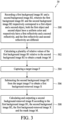
- Figure 3 is a schematic diagram of a background subtraction flow 30 according to embodiments of the present invention
- the background subtraction flow 30 is implemented by the image module 14 to generate the background-removed image R
- the background subtraction flow 30 comprises the following steps: Step 300: Recording a first background image B1 and a second background image B2, wherein the first background image B1 and the second background image B2 respectively correspond to a first object and a second object, both the first object and second object have a uniform color and respectively have a first reflectivity and a second reflectivity, and the first reflectivity and second reflectivity are different.
- Step 302 Calculating a plurality of relative values of the first background image B1 relative to the second background image B2 to obtain a mask image M.
- Step 304 Capturing a target image F.
- Step 306 Subtracting the second background image B2 from the target image F to obtain a first background-removed image X.
- Step 308 Calculating and outputting a second background-removed image R according to the first background image B1, the second background image B2, the first background-removed image X and the mask image M.
- the image module 14 records a first background image B 1 corresponding to a first object and a second background image B2 corresponding to a second object.
- the person operating the electronic device 1 covers a first object (which may be a uniformly all-black object having a first reflectivity) over a fingerprint sensing region (i.e., the region RGN above the image module 14) of the touch screen 12.
- the image capturing unit 140 captures at least one first image corresponding to the first object/all-black object.
- the operator covers a second object with a uniform color (which may be a uniformly all-white object having a second reflectivity) over the fingerprint sensing region (i.e., the region RGN above the image module 14) of the touch screen 12.
- the image capturing unit 140 captures at least one second image corresponding to the second object/all-white object.
- the background subtraction unit 142 calculates an average of the at least one first image so as to remove noise in the first image, thereby generating the first background image B1.
- the background subtraction unit 142 calculates an average of the at least one second image, so as to remove noise in the second image, thereby generating the second background image B2.
- the first background image B1 and the second background image B2 correspond respectively to the first object and the second object having different reflectivity (or different object colors). That is, the first reflectivity and the second reflectivity are different, and the first object and the second object are considered as the background object.
- the background subtraction unit 142 calculates a plurality of relative values of the first background image B1 relative to the second background image B2, so as to obtain a mask image M.
- the plurality of pixel values of the mask image M reflect the combine effect of the difference in the background object reflectivity and the different light transmittance of the touch-related component/material at different pixel positions.
- the mask image M may be subjected to a normalization calculation so that each mask pixel value of the mask image M is between 0 and 1.
- the image capturing unit 140 captures a target image F.
- the optical fingerprint identification system 10 implements optical fingerprint identification
- the user presses his/her finger(s) on the fingerprint sensing region (that is, the region RGN above the image module 14) of the touch screen 12, the target image F thus captured by the image capturing unit 140 comprises the fingerprint image.
- the background subtraction unit 142 may generate an inverse mask image N according to the mask image M, wherein the inverse mask image N is an inverse image of the mask image M.
- the background subtraction unit 142 may calculate a compensated image C/ a compensation coefficient g, so that the averaging value of pixels in any region of the image R*M is a constant value, or the averaging value of pixels in any region of the image R*N is another constant value.
- the background subtraction unit 142 may calculate a compensation coefficient g according to Equation 1.
- the background subtraction unit 142 calculates the compensation coefficient g according to the first mask-multiplied image W, the second mask-multiplied image WM, the first inverse mask-multiplied image B and the second inverse mask-multiplied image BN.
- mean(W), mean(B), mean(WM), and mean(BN) respectively mean the first mask-averaged value, the first inverse mask-averaged value, the second mask-averaged value, and the second inverse mask-averaged value corresponding to the first mask-multiplied image W, the first inverse mask-multiplied image B, the second mask-multiplied image WM, and the second inverse mask-multiplied image BN.
- Figure 4 is a schematic diagram of background images B1, B2, a mask image M, an inverse mask image N, target images F1 and F2, first background-removed images X1 and X2, and second background-removed images R1 and R2 according to embodiments of the present invention.
- the target image F1 is the target image F captured when the operator of the electronic device 1 covers an object of horizontal strips over the fingerprint sensing region (RGN) of the touch screen 12.
- the target image F2 is the target image F captured when the operator actually presses his/her finger(s) on the fingerprint sensing region (RGN).
- the first background-removed images X1 and X2 are results obtained from performing the step 306 to the target images F 1 and F2, respectively.
- the second background-removed images R1 and R2 are results obtained from performing the step 308 to the first background-removed images X1 and X2, respectively.
- the mask image M and the inverse mask image N are in the diamond shape, which reflects the image imaged by the touch-related components/materials/circuits, wherein some pixel positions in the mask image M is darker (having a smaller mask pixel value) whereas some pixel positions are brighter (having a larger mask pixel value).
- the inverse mask image N has a larger inverse mask pixel value at pixel positions with a smaller mask pixel value, and has a smaller inverse mask pixel value at pixel positions with a larger mask pixel value.
- the target image F1 has fine horizonal stripe signals, whereas the target image F2 has fine fingerprint signals.
- the first background-removed image X1 comprises a combined image of the image formed from the diamond-shaped circuit structure and the horizontal strips signals
- the first background-removed image X2 comprises a combined image of the image formed from the diamond-shaped circuit structure and the fingerprint signal.
- the image module 14 may effectively eliminate the image, corresponding to the diamond-shaped circuit structure, in the first background-removed images X1 and X2 by performing the step 308, so that the second background-removed image R1 has only the horizontal stripe signals, and the second background-removed image R2 has only the fingerprint signals.
- the first background-removed images X1 and X2 generated from the subtraction calculation of the first stage background are, in fact, the execution results of the existing background subtraction technology.
- the present invention further implements a second stage background subtraction calculation (that is, the step 308).
- the second background-removed images R1 and R2 generated by the second stage background subtraction calculation according to the present invention may further eliminate the interference to the image, as compared with the existing technology.
- the image module 14 may, during a calibration stage before the product delivery, first calculate the background images B1 and B2, mask image M and inverse mask image N, and store the same in a storage unit (not illustrated in Figure 1 ). After the product delivery, when the user presses his/her finger(s) on the fingerprint sensing region RGN, the image module 14 may capture the target image F in real-time and calculate the first background-removed image X and the second background-removed image R.
- the mask image M is not limited to the quotient of the first background image B1 and the second background image B2.
- the image module 14 may first implement a temperature compensation operation, so as to reduce the effect of the temperature on the background image B1 and B2. Moreover, considering the cases where the user does not press his/her finger(s) on the whole fingerprint sensing region RGN, the image module 14 may first implement image segmentation to the image captured by the image capturing unit 140, and the segmented images may be used as the target image F. Moreover, the background subtraction unit 142 may implement the binarization calculation to the mask image M, and the use of the binarized mask image M to calculate the second background-removed image R also falls within the scope of the present invention. Moreover, the first object and the second object are not limited to those of black or white and may have another color, as long as the first object and the second object have different reflectivity to light. These variations also fall within the scope of the present invention.
- the present invention uses objects having different reflectivity/color to create a first background image and a second background image, and uses a mask image generated according to the first background image and second background image, so as to use a first background-removed image generated from a first stage background subtraction (the existing background subtraction technology) calculation to further implement a second stage background subtraction calculation.
- the present invention may further eliminate the interference to the image.
Landscapes
- Engineering & Computer Science (AREA)
- Physics & Mathematics (AREA)
- General Physics & Mathematics (AREA)
- Theoretical Computer Science (AREA)
- Multimedia (AREA)
- Human Computer Interaction (AREA)
- Computer Vision & Pattern Recognition (AREA)
- Optics & Photonics (AREA)
- Image Input (AREA)
- Measurement Of The Respiration, Hearing Ability, Form, And Blood Characteristics Of Living Organisms (AREA)
Claims (12)
- Procédé de soustraction d'arrière-plan mis en oeuvre par un module d'image, dans lequel le module d'image est disposé sous une zone de détection d'empreinte digitale d'un écran tactile (12) d'un système d'identification d'empreinte digitale optique (10), et le procédé de soustraction d'arrière-plan comprend :l'enregistrement d'au moins une première image d'un premier objet, d'au moins une deuxième image d'un deuxième objet et d'une image cible (F), dans lequel le premier objet présente une couleur uniforme et présente une première réflectivité, le deuxième objet présente une couleur uniforme et présente une deuxième réflectivité, et la première réflectivité et la deuxième réflectivité sont différentes, dans lequel le premier objet couvre le module d'image lorsque l'au moins une première image est capturée et l'au moins un deuxième objet couvre le module d'image lorsque l'au moins une deuxième image est capturée ;la génération d'une première image d'arrière-plan (B1) par calcul d'une moyenne de l'au moins une première image de manière à éliminer un bruit dans la première image ;la génération d'une deuxième image d'arrière-plan (B2) par calcul d'une moyenne de l'au moins une deuxième image de manière à éliminer un bruit dans la deuxième image ;la division d'une pluralité de premières valeurs de pixel de la première image d'arrière-plan (B1) à la puissance d'un ou plus par une pluralité de deuxièmes valeurs de pixel de la deuxième image d'arrière-plan (B2) à la puissance d'un ou plus pour obtenir une pluralité de valeurs relatives de la première image d'arrière-plan par rapport à la deuxième image d'arrière-plan (B2) pour obtenir une image de masque (M) ;la soustraction de la deuxième image d'arrière-plan (B2) de l'image cible (F) pour obtenir une première image dont l'arrière-plan est supprimé (X) ; etle calcul et la sortie d'une deuxième image dont l'arrièreplan est supprimé (R), dans lequel une première image multipliée par le masque (W) est obtenue par multiplication de la première image dont l'arrière-plan est supprimé (X) par l'image de masque (M), dans lequel une image compensée (C) est calculée pour être positivement proportionnelle à la première image multipliée par le masque (W), et dans lequel la deuxième image dont l'arrière-plan est supprimé (R) est calculée par ajout de la première image dont l'arrière-plan est supprimé (X) et de l'image compensée (C) .
- Procédé de soustraction d'arrière-plan selon la revendication 1, dans lequel l'étape de calcul de la deuxième image dont l'arrière-plan est supprimé (R) comprend :la multiplication de la première image dont l'arrière-plan est supprimé (X) par l'image de masque (M) pour obtenir la première image multipliée par le masque (W) ;le calcul d'un coefficient de compensation (g) en fonction de la première image dont l'arrière-plan est supprimé (X), de l'image de masque (M) et de la première image multipliée par le masque (W) ;la multiplication de la première image multipliée par le masque (W) par le coefficient de compensation (g) pour obtenir l'image compensée (C) ; etl'ajout de la première image dont l'arrière-plan est supprimé (X) et de l'image compensée (C) pour générer la deuxième image dont l'arrière-plan est supprimé (R).
- Procédé de soustraction d'arrière-plan selon la revendication 2, dans lequel l'étape de calcul du coefficient de compensation (g) en fonction de la première image dont l'arrière-plan a été supprimé (X), de l'image de masque (M) et de la première image multipliée par le masque (W) comprend :la multiplication de la première image multipliée par le masque (W) par l'image de masque (M) pour obtenir une deuxième image multipliée par le masque (WM) ;la génération d'une image de masque inverse (N) en fonction de l'image de masque (M) ;la multiplication de la première image dont l'arrière-plan est supprimé (X) par l'image de masque inverse (N) pour obtenir une première image multipliée par le masque inverse (B) ;la multiplication de la première image multipliée par le masque inverse (B) par l'image de masque inverse (N) pour obtenir une deuxième image multipliée par le masque inverse (BN) ; etle calcul du coefficient de compensation (g) en fonction de la première image multipliée par le masque (W), de la deuxième image multipliée par le masque (WM), de la première image multipliée par le masque inverse (B) et de la deuxième image multipliée par le masque inverse (BN).
- Procédé de soustraction d'arrière-plan selon la revendication 3, dans lequel l'étape de génération de l'image de masque inverse (N) en fonction de l'image de masque (M) comprend :
la soustraction de l'image de masque (M) d'une image tout en blanc pour générer l'image de masque inverse (N). - Procédé de soustraction d'arrière-plan selon la revendication 4, dans lequel la pluralité de valeurs relatives sont soumises à une opération normalisée, de sorte que chaque valeur de pixel de masque dans l'image de masque (M) est comprise entre 0 et 1, et chaque valeur de pixel dans l'image tout en blanc est 1.
- Procédé de soustraction d'arrière-plan selon la revendication 3, dans lequel l'étape de calcul du coefficient de compensation (g) en fonction de la première image multipliée par le masque (W), de la deuxième image multipliée par le masque (WM), de la première image multipliée par le masque inverse (B) et de la deuxième image multipliée par le masque inverse (BN) comprend :l'obtention d'une première valeur dont la moyenne est faite de masque correspondant à la première image multipliée par le masque (W) ;l'obtention d'une première valeur dont la moyenne est faite de masque inverse correspondant à la première image multipliée par le masque inverse (B) ;la soustraction de la première valeur dont la moyenne est faite de masque inverse de la première valeur dont la moyenne est faite de masque pour générer un premier résultat soustrait ;l'obtention d'une deuxième valeur dont la moyenne est faite de masque correspondant à la deuxième image multipliée par le masque (WM) ;l'obtention d'une deuxième valeur dont la moyenne est faite de masque inverse correspondant à la deuxième image multipliée par le masque inverse (BN) ;la soustraction de la deuxième valeur dont la moyenne est faite de masque inverse de la deuxième valeur dont la moyenne est faite de masque pour générer un deuxième résultat soustrait ; etle calcul du coefficient de compensation, qui est proportionnel au rapport du premier résultat soustrait et du deuxième résultat soustrait.
- Module d'image (14), destiné à être disposé sous une zone de détection d'empreinte digitale d'un écran tactile (12) d'un système d'identification d'empreinte digitale optique (10), dans lequel le module d'image (14) comprend :une unité de capture d'image (140), configurée pour enregistrer au moins une première image d'un premier objet, au moins une deuxième image d'un deuxième objet et une image cible (F), dans lequel le premier objet présente une couleur uniforme et présente une première réflectivité, le deuxième objet présente une couleur uniforme et présente une deuxième réflectivité, et la première réflectivité et la deuxième réflectivité sont différentes, dans lequel le premier objet couvre le module d'image lorsque l'au moins une première image est capturée et l'au moins un deuxième objet couvre le module d'image lorsque l'au moins une deuxième image est capturée ;une unité de soustraction d'arrière-plan, configurée pour :générer une première image d'arrière-plan (B1) par calcul d'une moyenne de l'au moins une première image de manière à éliminer un bruit dans la première image ;générer une deuxième image d'arrière-plan (B2) par calcul d'une moyenne de l'au moins une deuxième image de manière à éliminer un bruit dans la deuxième image ;diviser une pluralité de premières valeurs de pixel de la première image d'arrière-plan (B1) à la puissance d'un ou plus par une pluralité de deuxièmes valeurs de pixel de la deuxième image d'arrière-plan (B2) à la puissance d'un ou plus pour obtenir une pluralité de valeurs relatives de la première image d'arrière-plan (B1) par rapport à la deuxième image d'arrière-plan (B2) pour obtenir une image de masque (M) ;soustraire la deuxième image d'arrière-plan (B2) de l'image cible (F) pour obtenir une première image dont l'arrière-plan est supprimé (X) ; etcalculer et sortir une deuxième image dont l'arrière-plan est supprimé (R), dans lequel une première image multipliée par le masque (W) est obtenue par multiplication de la première image dont l'arrière-plan est supprimé (X) par l'image de masque (M), dans lequel une image compensée (C) est calculée pour être positivement proportionnelle à la première image multipliée par le masque (W), et dans lequel la deuxième image dont l'arrière-plan est supprimé (R) est calculée par ajout de la première image dont l'arrière-plan est supprimé (X) et de l'image compensée (C) .
- Module d'image (14) selon la revendication 7, dans lequel l'unité de soustraction d'arrière-plan est en outre configurée pour calculer la deuxième image dont l'arrière-plan est supprimé (R) par :multiplication de la première image dont l'arrière-plan est supprimé (X) par l'image de masque (M) pour obtenir une première image multipliée par le masque (W) ;calcul d'un coefficient de compensation (g) en fonction de la première image dont l'arrière-plan est supprimé (X), de l'image de masque (M) et de la première image multipliée par le masque (W) ;multiplication de la première image multipliée par le masque (W) par le coefficient de compensation (g) pour obtenir l'image compensée (C) ; etajout de la première image dont l'arrière-plan est supprimé (X) et de l'image compensée (C) pour générer la deuxième image dont l'arrière-plan est supprimé (R).
- Module d'image (14) selon la revendication 8, dans lequel l'unité de soustraction d'arrière-plan est en outre configurée pour calculer le coefficient de compensation (g) en fonction de la première image dont l'arrière-plan est supprimé (X), de l'image de masque (M) et de la première image multipliée par le masque (W) par :multiplication de la première image multipliée par le masque (W) par l'image de masque (M) pour obtenir une deuxième image multipliée par le masque (WM) ;génération d'une image de masque inverse (N) en fonction de l'image de masque (M) ;multiplication de la première image dont l'arrière-plan est supprimé (X) par l'image de masque inverse (N) pour obtenir une première image multipliée par le masque inverse (B) ;multiplication de la première image multipliée par le masque inverse (B) par l'image de masque inverse (N) pour obtenir une deuxième image multipliée par le masque inverse (BN) ; etcalcul du coefficient de compensation (g) en fonction de la première image multipliée par le masque (W), de la deuxième image multipliée par le masque (WM), de la première image multipliée par le masque inverse (B) et de la deuxième image multipliée par le masque inverse (BN).
- Module d'image (14) selon la revendication 9, dans lequel l'unité de soustraction d'arrière-plan est en outre configurée pour générer l'image de masque inverse (N) en fonction de l'image de masque (M) par :soustraction de l'image de masque (M) d'une image tout en blanc pour générer l'image de masque inverse (N) ;dans lequel la pluralité de valeurs relatives sont soumises à une opération normalisée de sorte que chaque valeur de pixel de masque dans l'image de masque (M) est comprise entre 0 et 1, et chaque valeur de pixel tout en blanc de l'image tout en blanc est 1.
- Module d'image (14) selon la revendication 9, dans lequel l'unité de soustraction d'arrière-plan est en outre configurée pour calculer le coefficient de compensation (g) en fonction de la première image multipliée par le masque (W), de la deuxième image multipliée par le masque (WM), de la première image multipliée par le masque inverse (B) et de la deuxième image multipliée par le masque inverse (BN) par :obtention d'une première valeur dont la moyenne est faite de masque correspondant à la première image multipliée par le masque (W) ;obtention d'une première valeur dont la moyenne est faite de masque inverse correspondant à la première image multipliée par le masque inverse (B) ;soustraction de la première valeur dont la moyenne est faite de masque inverse de la première valeur dont la moyenne est faite de masque pour générer un premier résultat soustrait ;obtention d'une deuxième valeur dont la moyenne est faite de masque correspondant à la deuxième image multipliée par le masque (WM) ;l'obtention d'une deuxième valeur dont la moyenne est faite de masque inverse correspondant à la deuxième image multipliée par le masque inverse (BN) ;soustraction de la deuxième valeur dont la moyenne est faite de masque inverse de la deuxième valeur dont la moyenne est faite de masque pour générer un deuxième résultat soustrait ; etcalcul du coefficient de compensation, qui est proportionnel au rapport du premier résultat soustrait et du deuxième résultat soustrait.
- Système d'identification d'empreinte digitale optique (10), disposé dans un dispositif électronique (1), dans lequel le système d'identification d'empreinte digitale optique (10) comprend :un module d'identification d'empreinte digitale (16) ; et un module d'image (14) selon l'une quelconque des revendications 7-11 dans lequel le module d'image (14) est couplé au module d'identification d'empreinte digitale (16) ;dans lequel le module d'identification d'empreinte digitale (16) reçoit la deuxième image dont l'arrière-plan est supprimé (R) pour mettre en œuvre une identification d'empreinte digitale en fonction de la deuxième image dont l'arrière-plan est supprimé (R).
Applications Claiming Priority (1)
| Application Number | Priority Date | Filing Date | Title |
|---|---|---|---|
| PCT/CN2017/112868 WO2019100329A1 (fr) | 2017-11-24 | 2017-11-24 | Procédé d'élimination d'arrière-plan, module d'image et système d'identification d'empreinte digitale optique |
Publications (3)
| Publication Number | Publication Date |
|---|---|
| EP3594846A1 EP3594846A1 (fr) | 2020-01-15 |
| EP3594846A4 EP3594846A4 (fr) | 2020-05-20 |
| EP3594846B1 true EP3594846B1 (fr) | 2024-10-23 |
Family
ID=62142038
Family Applications (1)
| Application Number | Title | Priority Date | Filing Date |
|---|---|---|---|
| EP17933026.1A Active EP3594846B1 (fr) | 2017-11-24 | 2017-11-24 | Procédé d'élimination d'arrière-plan, module d'image et système d'identification d'empreinte digitale optique |
Country Status (4)
| Country | Link |
|---|---|
| US (1) | US11182586B2 (fr) |
| EP (1) | EP3594846B1 (fr) |
| CN (1) | CN108064386B (fr) |
| WO (1) | WO2019100329A1 (fr) |
Families Citing this family (39)
| Publication number | Priority date | Publication date | Assignee | Title |
|---|---|---|---|---|
| US10445547B2 (en) | 2016-05-04 | 2019-10-15 | Invensense, Inc. | Device mountable packaging of ultrasonic transducers |
| US10315222B2 (en) | 2016-05-04 | 2019-06-11 | Invensense, Inc. | Two-dimensional array of CMOS control elements |
| US10452887B2 (en) | 2016-05-10 | 2019-10-22 | Invensense, Inc. | Operating a fingerprint sensor comprised of ultrasonic transducers |
| US10441975B2 (en) | 2016-05-10 | 2019-10-15 | Invensense, Inc. | Supplemental sensor modes and systems for ultrasonic transducers |
| US10562070B2 (en) | 2016-05-10 | 2020-02-18 | Invensense, Inc. | Receive operation of an ultrasonic sensor |
| US10706835B2 (en) | 2016-05-10 | 2020-07-07 | Invensense, Inc. | Transmit beamforming of a two-dimensional array of ultrasonic transducers |
| US11673165B2 (en) | 2016-05-10 | 2023-06-13 | Invensense, Inc. | Ultrasonic transducer operable in a surface acoustic wave (SAW) mode |
| US10539539B2 (en) | 2016-05-10 | 2020-01-21 | Invensense, Inc. | Operation of an ultrasonic sensor |
| US10474862B2 (en) | 2017-06-01 | 2019-11-12 | Invensense, Inc. | Image generation in an electronic device using ultrasonic transducers |
| EP3594846B1 (fr) | 2017-11-24 | 2024-10-23 | Shenzhen Goodix Technology Co., Ltd. | Procédé d'élimination d'arrière-plan, module d'image et système d'identification d'empreinte digitale optique |
| US10997388B2 (en) | 2017-12-01 | 2021-05-04 | Invensense, Inc. | Darkfield contamination detection |
| WO2019109010A1 (fr) | 2017-12-01 | 2019-06-06 | Invensense, Inc. | Suivi de fond noir |
| US11151355B2 (en) | 2018-01-24 | 2021-10-19 | Invensense, Inc. | Generation of an estimated fingerprint |
| US10755067B2 (en) | 2018-03-22 | 2020-08-25 | Invensense, Inc. | Operating a fingerprint sensor comprised of ultrasonic transducers |
| CN109389071A (zh) * | 2018-09-29 | 2019-02-26 | 京东方科技集团股份有限公司 | 指纹检测方法与指纹图像补偿方法及装置、电子装置 |
| CN110543851B (zh) | 2018-11-30 | 2022-10-21 | 神盾股份有限公司 | 具有指纹感测功能的电子装置以及指纹图像处理方法 |
| CN111310517B (zh) * | 2018-12-11 | 2024-01-19 | 上海耕岩智能科技有限公司 | 一种基于sim卡的认证方法、装置、系统 |
| US10936843B2 (en) | 2018-12-28 | 2021-03-02 | Invensense, Inc. | Segmented image acquisition |
| CN110097031B (zh) * | 2019-05-14 | 2023-07-25 | 上海菲戈恩微电子科技有限公司 | 一种屏下光学指纹图像的校正方法和装置 |
| US11188735B2 (en) | 2019-06-24 | 2021-11-30 | Invensense, Inc. | Fake finger detection using ridge features |
| WO2020264046A1 (fr) | 2019-06-25 | 2020-12-30 | Invensense, Inc. | Détection de faux doigt basée sur des caractéristiques transitoires |
| US11216632B2 (en) | 2019-07-17 | 2022-01-04 | Invensense, Inc. | Ultrasonic fingerprint sensor with a contact layer of non-uniform thickness |
| US11176345B2 (en) | 2019-07-17 | 2021-11-16 | Invensense, Inc. | Ultrasonic fingerprint sensor with a contact layer of non-uniform thickness |
| CN110334694B (zh) * | 2019-07-18 | 2023-05-09 | 上海菲戈恩微电子科技有限公司 | 一种基于偏振光的屏下光学指纹防攻击方法 |
| US11232549B2 (en) | 2019-08-23 | 2022-01-25 | Invensense, Inc. | Adapting a quality threshold for a fingerprint image |
| US11392789B2 (en) | 2019-10-21 | 2022-07-19 | Invensense, Inc. | Fingerprint authentication using a synthetic enrollment image |
| KR102879591B1 (ko) * | 2019-10-22 | 2025-10-31 | 삼성디스플레이 주식회사 | 표시 장치 |
| CN112101194B (zh) | 2020-01-21 | 2024-09-13 | 神盾股份有限公司 | 电子装置及其操作方法 |
| TWM601349U (zh) * | 2020-01-21 | 2020-09-11 | 神盾股份有限公司 | 影像掃描裝置 |
| EP4100176B1 (fr) | 2020-03-09 | 2024-10-09 | InvenSense, Inc. | Capteur d'empreintes digitales à ultrasons doté d'une couche de contact d'épaisseur non uniforme |
| US11243300B2 (en) | 2020-03-10 | 2022-02-08 | Invensense, Inc. | Operating a fingerprint sensor comprised of ultrasonic transducers and a presence sensor |
| KR20210128797A (ko) * | 2020-04-17 | 2021-10-27 | 삼성전자주식회사 | 사용자의 지문을 인식하는 전자 장치 및 동작 방법 |
| US11328165B2 (en) | 2020-04-24 | 2022-05-10 | Invensense, Inc. | Pressure-based activation of fingerprint spoof detection |
| US11995909B2 (en) | 2020-07-17 | 2024-05-28 | Tdk Corporation | Multipath reflection correction |
| US12174295B2 (en) | 2020-08-07 | 2024-12-24 | Tdk Corporation | Acoustic multipath correction |
| CN113486738B (zh) * | 2021-06-22 | 2024-11-08 | 维沃移动通信有限公司 | 指纹识别方法、装置、电子设备和可读存储介质 |
| US12416807B2 (en) | 2021-08-20 | 2025-09-16 | Tdk Corporation | Retinal projection display system |
| US12260050B2 (en) | 2021-08-25 | 2025-03-25 | Tdk Corporation | Differential receive at an ultrasonic transducer |
| US11790690B1 (en) * | 2022-11-21 | 2023-10-17 | Novatek Microelectronics Corp. | Fingerprint recognition device, fingerprint recognition method and method of generating moire pattern image |
Family Cites Families (16)
| Publication number | Priority date | Publication date | Assignee | Title |
|---|---|---|---|---|
| US6125192A (en) * | 1997-04-21 | 2000-09-26 | Digital Persona, Inc. | Fingerprint recognition system |
| CN101210876A (zh) * | 2007-12-25 | 2008-07-02 | 浙江大学 | 基于可见/近红外多光谱成像的水稻养分信息测量方法 |
| CN101339613B (zh) * | 2008-08-12 | 2010-11-17 | 中国地质科学院矿产资源研究所 | 一种遥感图像背景噪声减弱方法 |
| EP2343633A4 (fr) * | 2008-10-21 | 2013-06-12 | Sony Corp | Dispositif de capture d'image, dispositif d'affichage et de capture d'image et appareil électronique |
| NO329897B1 (no) * | 2008-12-19 | 2011-01-24 | Tandberg Telecom As | Fremgangsmate for raskere ansiktsdeteksjon |
| CN102446034B (zh) * | 2010-10-13 | 2014-05-07 | 原相科技股份有限公司 | 光学触控系统及其物件侦测方法 |
| CN102999750B (zh) * | 2012-12-31 | 2015-08-12 | 清华大学 | 一种去除背景干扰的现场指纹增强方法 |
| JP2014182476A (ja) * | 2013-03-18 | 2014-09-29 | Fuji Xerox Co Ltd | 操作履歴情報保存装置、画像処理装置、操作履歴情報保存制御プログラム |
| JP6751359B2 (ja) * | 2016-01-27 | 2020-09-02 | 株式会社ジャパンディスプレイ | 指紋検出装置 |
| EP3254235B1 (fr) * | 2016-01-31 | 2023-07-12 | Shenzhen Goodix Technology Co., Ltd. | Module de capteur optique de sous-écran permettant la détection d'empreintes digitales sur écran |
| CN106203365B (zh) * | 2016-07-14 | 2019-02-12 | 浙江赢视科技有限公司 | 增益调节处理的指纹成像方法 |
| CN106228123B (zh) * | 2016-07-14 | 2019-02-12 | 浙江赢视科技有限公司 | 自动调整处理的指纹识别器及其识别方法 |
| CN106940488B (zh) * | 2017-04-27 | 2019-07-12 | 上海天马微电子有限公司 | 显示面板及显示装置 |
| CN106949488B (zh) | 2017-05-09 | 2022-10-21 | 江苏中科机械有限公司 | 具有高效密封旋转式换向阀的蓄热燃烧装置 |
| CN107454963B (zh) * | 2017-06-16 | 2021-11-30 | 深圳市汇顶科技股份有限公司 | 指纹图像处理方法及光学指纹辨识系统 |
| EP3594846B1 (fr) | 2017-11-24 | 2024-10-23 | Shenzhen Goodix Technology Co., Ltd. | Procédé d'élimination d'arrière-plan, module d'image et système d'identification d'empreinte digitale optique |
-
2017
- 2017-11-24 EP EP17933026.1A patent/EP3594846B1/fr active Active
- 2017-11-24 CN CN201780001862.8A patent/CN108064386B/zh active Active
- 2017-11-24 WO PCT/CN2017/112868 patent/WO2019100329A1/fr not_active Ceased
-
2019
- 2019-10-18 US US16/657,852 patent/US11182586B2/en active Active
Also Published As
| Publication number | Publication date |
|---|---|
| CN108064386B (zh) | 2022-04-05 |
| WO2019100329A1 (fr) | 2019-05-31 |
| EP3594846A4 (fr) | 2020-05-20 |
| EP3594846A1 (fr) | 2020-01-15 |
| CN108064386A (zh) | 2018-05-22 |
| US11182586B2 (en) | 2021-11-23 |
| US20200050828A1 (en) | 2020-02-13 |
Similar Documents
| Publication | Publication Date | Title |
|---|---|---|
| EP3594846B1 (fr) | Procédé d'élimination d'arrière-plan, module d'image et système d'identification d'empreinte digitale optique | |
| CN107636686B (zh) | 指纹采集的方法、装置、芯片和终端设备 | |
| CN107454963B (zh) | 指纹图像处理方法及光学指纹辨识系统 | |
| CN107690653B (zh) | 获取指纹图像的方法、装置和终端设备 | |
| US8824792B2 (en) | Image element brightness adjustment | |
| WO2020063111A1 (fr) | Procédé et appareil de détection d'empreinte, procédé et appareil de compensation d'image d'empreinte, et appareil électronique | |
| Abileah et al. | 59.3: Integrated Optical Touch Panel in a 14.1 ″AMLCD | |
| US20050220329A1 (en) | Method of focusing a fingerprint image and a fingerprint sensing device | |
| US20080285813A1 (en) | Apparatus and recognition method for capturing ear biometric in wireless communication devices | |
| CN101847062B (zh) | 信息输入设备、信息输入/输出设备和电子设备 | |
| CN110070006A (zh) | 指纹识别方法、电子装置及计算机可读取介质 | |
| US20200175248A1 (en) | Sensor Device and Flicker Noise Mitigating Method | |
| WO2021083059A1 (fr) | Procédé de reconstruction d'image à super-résolution, appareil de reconstruction d'image à super-résolution et dispositif électronique | |
| CN108713202A (zh) | 用于指纹识别的方法、装置和电子设备 | |
| CN111586311A (zh) | 图像采集的方法 | |
| US20220067330A1 (en) | Calibration method, electronic device, and non-transitory computer-readable storage medium | |
| US10977822B2 (en) | Fingerprint image enhancement method and fingerprint image module | |
| CN109948588A (zh) | 一种信息处理方法及电子设备 | |
| CN107360342A (zh) | 一种图像数据的处理方法和移动终端 | |
| CN112565601B (zh) | 图像处理方法、装置、移动终端及存储介质 | |
| CN111861965A (zh) | 图像逆光检测方法、图像逆光检测装置及终端设备 | |
| CN111611881B (zh) | 生物特征采集装置和电子设备 | |
| CN113065487B (zh) | 指纹识别的方法、装置和电子设备 | |
| CN115695679B (zh) | 三联深度模组匹配方法和装置、移动终端、介质和芯片 | |
| CN215987334U (zh) | 一种获取皮肤纹路图像的模组以及电子设备 |
Legal Events
| Date | Code | Title | Description |
|---|---|---|---|
| STAA | Information on the status of an ep patent application or granted ep patent |
Free format text: STATUS: THE INTERNATIONAL PUBLICATION HAS BEEN MADE |
|
| PUAI | Public reference made under article 153(3) epc to a published international application that has entered the european phase |
Free format text: ORIGINAL CODE: 0009012 |
|
| STAA | Information on the status of an ep patent application or granted ep patent |
Free format text: STATUS: REQUEST FOR EXAMINATION WAS MADE |
|
| 17P | Request for examination filed |
Effective date: 20191010 |
|
| AK | Designated contracting states |
Kind code of ref document: A1 Designated state(s): AL AT BE BG CH CY CZ DE DK EE ES FI FR GB GR HR HU IE IS IT LI LT LU LV MC MK MT NL NO PL PT RO RS SE SI SK SM TR |
|
| AX | Request for extension of the european patent |
Extension state: BA ME |
|
| A4 | Supplementary search report drawn up and despatched |
Effective date: 20200420 |
|
| RIC1 | Information provided on ipc code assigned before grant |
Ipc: G06T 5/50 20060101ALN20200414BHEP Ipc: G06T 5/00 20060101ALN20200414BHEP Ipc: G06K 9/00 20060101AFI20200414BHEP |
|
| DAV | Request for validation of the european patent (deleted) | ||
| DAX | Request for extension of the european patent (deleted) | ||
| STAA | Information on the status of an ep patent application or granted ep patent |
Free format text: STATUS: EXAMINATION IS IN PROGRESS |
|
| 17Q | First examination report despatched |
Effective date: 20210720 |
|
| REG | Reference to a national code |
Ref country code: DE Ref legal event code: R079 Free format text: PREVIOUS MAIN CLASS: G06K0009000000 Ref country code: DE Ref legal event code: R079 Ref document number: 602017085726 Country of ref document: DE Free format text: PREVIOUS MAIN CLASS: G06K0009000000 Ipc: G06V0040120000 |
|
| GRAP | Despatch of communication of intention to grant a patent |
Free format text: ORIGINAL CODE: EPIDOSNIGR1 |
|
| STAA | Information on the status of an ep patent application or granted ep patent |
Free format text: STATUS: GRANT OF PATENT IS INTENDED |
|
| RIC1 | Information provided on ipc code assigned before grant |
Ipc: G06T 5/50 20060101ALN20240718BHEP Ipc: G06T 5/00 20060101ALN20240718BHEP Ipc: G06V 10/25 20220101ALI20240718BHEP Ipc: G06V 40/12 20220101AFI20240718BHEP |
|
| RIC1 | Information provided on ipc code assigned before grant |
Ipc: G06T 5/50 20060101ALN20240722BHEP Ipc: G06T 5/00 20060101ALN20240722BHEP Ipc: G06V 10/25 20220101ALI20240722BHEP Ipc: G06V 40/12 20220101AFI20240722BHEP |
|
| INTG | Intention to grant announced |
Effective date: 20240801 |
|
| GRAS | Grant fee paid |
Free format text: ORIGINAL CODE: EPIDOSNIGR3 |
|
| GRAA | (expected) grant |
Free format text: ORIGINAL CODE: 0009210 |
|
| STAA | Information on the status of an ep patent application or granted ep patent |
Free format text: STATUS: THE PATENT HAS BEEN GRANTED |
|
| AK | Designated contracting states |
Kind code of ref document: B1 Designated state(s): AL AT BE BG CH CY CZ DE DK EE ES FI FR GB GR HR HU IE IS IT LI LT LU LV MC MK MT NL NO PL PT RO RS SE SI SK SM TR |
|
| REG | Reference to a national code |
Ref country code: GB Ref legal event code: FG4D |
|
| REG | Reference to a national code |
Ref country code: CH Ref legal event code: EP |
|
| REG | Reference to a national code |
Ref country code: DE Ref legal event code: R096 Ref document number: 602017085726 Country of ref document: DE |
|
| REG | Reference to a national code |
Ref country code: IE Ref legal event code: FG4D |
|
| REG | Reference to a national code |
Ref country code: LT Ref legal event code: MG9D |
|
| REG | Reference to a national code |
Ref country code: NL Ref legal event code: MP Effective date: 20241023 |
|
| REG | Reference to a national code |
Ref country code: AT Ref legal event code: MK05 Ref document number: 1735484 Country of ref document: AT Kind code of ref document: T Effective date: 20241023 |
|
| PG25 | Lapsed in a contracting state [announced via postgrant information from national office to epo] |
Ref country code: NL Free format text: LAPSE BECAUSE OF FAILURE TO SUBMIT A TRANSLATION OF THE DESCRIPTION OR TO PAY THE FEE WITHIN THE PRESCRIBED TIME-LIMIT Effective date: 20241023 |
|
| PG25 | Lapsed in a contracting state [announced via postgrant information from national office to epo] |
Ref country code: NL Free format text: LAPSE BECAUSE OF FAILURE TO SUBMIT A TRANSLATION OF THE DESCRIPTION OR TO PAY THE FEE WITHIN THE PRESCRIBED TIME-LIMIT Effective date: 20241023 |
|
| PG25 | Lapsed in a contracting state [announced via postgrant information from national office to epo] |
Ref country code: HR Free format text: LAPSE BECAUSE OF FAILURE TO SUBMIT A TRANSLATION OF THE DESCRIPTION OR TO PAY THE FEE WITHIN THE PRESCRIBED TIME-LIMIT Effective date: 20241023 Ref country code: PT Free format text: LAPSE BECAUSE OF FAILURE TO SUBMIT A TRANSLATION OF THE DESCRIPTION OR TO PAY THE FEE WITHIN THE PRESCRIBED TIME-LIMIT Effective date: 20250224 Ref country code: IS Free format text: LAPSE BECAUSE OF FAILURE TO SUBMIT A TRANSLATION OF THE DESCRIPTION OR TO PAY THE FEE WITHIN THE PRESCRIBED TIME-LIMIT Effective date: 20250223 |
|
| PG25 | Lapsed in a contracting state [announced via postgrant information from national office to epo] |
Ref country code: FI Free format text: LAPSE BECAUSE OF FAILURE TO SUBMIT A TRANSLATION OF THE DESCRIPTION OR TO PAY THE FEE WITHIN THE PRESCRIBED TIME-LIMIT Effective date: 20241023 |
|
| PG25 | Lapsed in a contracting state [announced via postgrant information from national office to epo] |
Ref country code: BG Free format text: LAPSE BECAUSE OF FAILURE TO SUBMIT A TRANSLATION OF THE DESCRIPTION OR TO PAY THE FEE WITHIN THE PRESCRIBED TIME-LIMIT Effective date: 20241023 |
|
| PG25 | Lapsed in a contracting state [announced via postgrant information from national office to epo] |
Ref country code: ES Free format text: LAPSE BECAUSE OF FAILURE TO SUBMIT A TRANSLATION OF THE DESCRIPTION OR TO PAY THE FEE WITHIN THE PRESCRIBED TIME-LIMIT Effective date: 20241023 |
|
| PG25 | Lapsed in a contracting state [announced via postgrant information from national office to epo] |
Ref country code: NO Free format text: LAPSE BECAUSE OF FAILURE TO SUBMIT A TRANSLATION OF THE DESCRIPTION OR TO PAY THE FEE WITHIN THE PRESCRIBED TIME-LIMIT Effective date: 20250123 |
|
| PG25 | Lapsed in a contracting state [announced via postgrant information from national office to epo] |
Ref country code: GR Free format text: LAPSE BECAUSE OF FAILURE TO SUBMIT A TRANSLATION OF THE DESCRIPTION OR TO PAY THE FEE WITHIN THE PRESCRIBED TIME-LIMIT Effective date: 20250124 Ref country code: AT Free format text: LAPSE BECAUSE OF FAILURE TO SUBMIT A TRANSLATION OF THE DESCRIPTION OR TO PAY THE FEE WITHIN THE PRESCRIBED TIME-LIMIT Effective date: 20241023 Ref country code: LV Free format text: LAPSE BECAUSE OF FAILURE TO SUBMIT A TRANSLATION OF THE DESCRIPTION OR TO PAY THE FEE WITHIN THE PRESCRIBED TIME-LIMIT Effective date: 20241023 |
|
| PG25 | Lapsed in a contracting state [announced via postgrant information from national office to epo] |
Ref country code: PL Free format text: LAPSE BECAUSE OF FAILURE TO SUBMIT A TRANSLATION OF THE DESCRIPTION OR TO PAY THE FEE WITHIN THE PRESCRIBED TIME-LIMIT Effective date: 20241023 |
|
| PG25 | Lapsed in a contracting state [announced via postgrant information from national office to epo] |
Ref country code: RS Free format text: LAPSE BECAUSE OF FAILURE TO SUBMIT A TRANSLATION OF THE DESCRIPTION OR TO PAY THE FEE WITHIN THE PRESCRIBED TIME-LIMIT Effective date: 20250123 |
|
| REG | Reference to a national code |
Ref country code: CH Ref legal event code: PL |
|
| PG25 | Lapsed in a contracting state [announced via postgrant information from national office to epo] |
Ref country code: SM Free format text: LAPSE BECAUSE OF FAILURE TO SUBMIT A TRANSLATION OF THE DESCRIPTION OR TO PAY THE FEE WITHIN THE PRESCRIBED TIME-LIMIT Effective date: 20241023 |
|
| PG25 | Lapsed in a contracting state [announced via postgrant information from national office to epo] |
Ref country code: MC Free format text: LAPSE BECAUSE OF FAILURE TO SUBMIT A TRANSLATION OF THE DESCRIPTION OR TO PAY THE FEE WITHIN THE PRESCRIBED TIME-LIMIT Effective date: 20241023 |
|
| PG25 | Lapsed in a contracting state [announced via postgrant information from national office to epo] |
Ref country code: DK Free format text: LAPSE BECAUSE OF FAILURE TO SUBMIT A TRANSLATION OF THE DESCRIPTION OR TO PAY THE FEE WITHIN THE PRESCRIBED TIME-LIMIT Effective date: 20241023 |
|
| PG25 | Lapsed in a contracting state [announced via postgrant information from national office to epo] |
Ref country code: LU Free format text: LAPSE BECAUSE OF NON-PAYMENT OF DUE FEES Effective date: 20241124 |
|
| REG | Reference to a national code |
Ref country code: CH Ref legal event code: PL |
|
| PG25 | Lapsed in a contracting state [announced via postgrant information from national office to epo] |
Ref country code: EE Free format text: LAPSE BECAUSE OF FAILURE TO SUBMIT A TRANSLATION OF THE DESCRIPTION OR TO PAY THE FEE WITHIN THE PRESCRIBED TIME-LIMIT Effective date: 20241023 |
|
| PG25 | Lapsed in a contracting state [announced via postgrant information from national office to epo] |
Ref country code: CH Free format text: LAPSE BECAUSE OF NON-PAYMENT OF DUE FEES Effective date: 20241130 |
|
| PG25 | Lapsed in a contracting state [announced via postgrant information from national office to epo] |
Ref country code: RO Free format text: LAPSE BECAUSE OF FAILURE TO SUBMIT A TRANSLATION OF THE DESCRIPTION OR TO PAY THE FEE WITHIN THE PRESCRIBED TIME-LIMIT Effective date: 20241023 |
|
| REG | Reference to a national code |
Ref country code: DE Ref legal event code: R097 Ref document number: 602017085726 Country of ref document: DE |
|
| PG25 | Lapsed in a contracting state [announced via postgrant information from national office to epo] |
Ref country code: SK Free format text: LAPSE BECAUSE OF FAILURE TO SUBMIT A TRANSLATION OF THE DESCRIPTION OR TO PAY THE FEE WITHIN THE PRESCRIBED TIME-LIMIT Effective date: 20241023 |
|
| PG25 | Lapsed in a contracting state [announced via postgrant information from national office to epo] |
Ref country code: CZ Free format text: LAPSE BECAUSE OF FAILURE TO SUBMIT A TRANSLATION OF THE DESCRIPTION OR TO PAY THE FEE WITHIN THE PRESCRIBED TIME-LIMIT Effective date: 20241023 |
|
| PG25 | Lapsed in a contracting state [announced via postgrant information from national office to epo] |
Ref country code: IT Free format text: LAPSE BECAUSE OF FAILURE TO SUBMIT A TRANSLATION OF THE DESCRIPTION OR TO PAY THE FEE WITHIN THE PRESCRIBED TIME-LIMIT Effective date: 20241023 |
|
| REG | Reference to a national code |
Ref country code: BE Ref legal event code: MM Effective date: 20241130 |
|
| PLBE | No opposition filed within time limit |
Free format text: ORIGINAL CODE: 0009261 |
|
| STAA | Information on the status of an ep patent application or granted ep patent |
Free format text: STATUS: NO OPPOSITION FILED WITHIN TIME LIMIT |
|
| PG25 | Lapsed in a contracting state [announced via postgrant information from national office to epo] |
Ref country code: SE Free format text: LAPSE BECAUSE OF FAILURE TO SUBMIT A TRANSLATION OF THE DESCRIPTION OR TO PAY THE FEE WITHIN THE PRESCRIBED TIME-LIMIT Effective date: 20241023 |
|
| 26N | No opposition filed |
Effective date: 20250724 |
|
| PG25 | Lapsed in a contracting state [announced via postgrant information from national office to epo] |
Ref country code: BE Free format text: LAPSE BECAUSE OF NON-PAYMENT OF DUE FEES Effective date: 20241130 |
|
| PG25 | Lapsed in a contracting state [announced via postgrant information from national office to epo] |
Ref country code: FR Free format text: LAPSE BECAUSE OF NON-PAYMENT OF DUE FEES Effective date: 20241223 |
|
| PG25 | Lapsed in a contracting state [announced via postgrant information from national office to epo] |
Ref country code: IE Free format text: LAPSE BECAUSE OF NON-PAYMENT OF DUE FEES Effective date: 20241124 |
|
| PGFP | Annual fee paid to national office [announced via postgrant information from national office to epo] |
Ref country code: DE Payment date: 20251111 Year of fee payment: 9 |
|
| PGFP | Annual fee paid to national office [announced via postgrant information from national office to epo] |
Ref country code: GB Payment date: 20251114 Year of fee payment: 9 |
|
| PG25 | Lapsed in a contracting state [announced via postgrant information from national office to epo] |
Ref country code: HU Free format text: LAPSE BECAUSE OF FAILURE TO SUBMIT A TRANSLATION OF THE DESCRIPTION OR TO PAY THE FEE WITHIN THE PRESCRIBED TIME-LIMIT; INVALID AB INITIO Effective date: 20171124 |
|
| PG25 | Lapsed in a contracting state [announced via postgrant information from national office to epo] |
Ref country code: CY Free format text: LAPSE BECAUSE OF FAILURE TO SUBMIT A TRANSLATION OF THE DESCRIPTION OR TO PAY THE FEE WITHIN THE PRESCRIBED TIME-LIMIT; INVALID AB INITIO Effective date: 20171124 |