EP3594531B2 - Sensorsystem des kettenzustands eines fahrrads - Google Patents
Sensorsystem des kettenzustands eines fahrrads Download PDFInfo
- Publication number
- EP3594531B2 EP3594531B2 EP19182468.9A EP19182468A EP3594531B2 EP 3594531 B2 EP3594531 B2 EP 3594531B2 EP 19182468 A EP19182468 A EP 19182468A EP 3594531 B2 EP3594531 B2 EP 3594531B2
- Authority
- EP
- European Patent Office
- Prior art keywords
- drive chain
- bicycle
- sound
- sprocket
- sensor
- Prior art date
- Legal status (The legal status is an assumption and is not a legal conclusion. Google has not performed a legal analysis and makes no representation as to the accuracy of the status listed.)
- Active
Links
Images


Classifications
-
- B—PERFORMING OPERATIONS; TRANSPORTING
- B62—LAND VEHICLES FOR TRAVELLING OTHERWISE THAN ON RAILS
- B62J—CYCLE SADDLES OR SEATS; AUXILIARY DEVICES OR ACCESSORIES SPECIALLY ADAPTED TO CYCLES AND NOT OTHERWISE PROVIDED FOR, e.g. ARTICLE CARRIERS OR CYCLE PROTECTORS
- B62J45/00—Electrical equipment arrangements specially adapted for use as accessories on cycles, not otherwise provided for
- B62J45/40—Sensor arrangements; Mounting thereof
- B62J45/41—Sensor arrangements; Mounting thereof characterised by the type of sensor
-
- B—PERFORMING OPERATIONS; TRANSPORTING
- B62—LAND VEHICLES FOR TRAVELLING OTHERWISE THAN ON RAILS
- B62M—RIDER PROPULSION OF WHEELED VEHICLES OR SLEDGES; POWERED PROPULSION OF SLEDGES OR SINGLE-TRACK CYCLES; TRANSMISSIONS SPECIALLY ADAPTED FOR SUCH VEHICLES
- B62M9/00—Transmissions characterised by use of an endless chain, belt, or the like
- B62M9/04—Transmissions characterised by use of an endless chain, belt, or the like of changeable ratio
- B62M9/06—Transmissions characterised by use of an endless chain, belt, or the like of changeable ratio using a single chain, belt, or the like
- B62M9/10—Transmissions characterised by use of an endless chain, belt, or the like of changeable ratio using a single chain, belt, or the like involving different-sized wheels, e.g. rear sprocket chain wheels selectively engaged by the chain, belt, or the like
- B62M9/12—Transmissions characterised by use of an endless chain, belt, or the like of changeable ratio using a single chain, belt, or the like involving different-sized wheels, e.g. rear sprocket chain wheels selectively engaged by the chain, belt, or the like the chain, belt, or the like being laterally shiftable, e.g. using a rear derailleur
-
- B—PERFORMING OPERATIONS; TRANSPORTING
- B62—LAND VEHICLES FOR TRAVELLING OTHERWISE THAN ON RAILS
- B62J—CYCLE SADDLES OR SEATS; AUXILIARY DEVICES OR ACCESSORIES SPECIALLY ADAPTED TO CYCLES AND NOT OTHERWISE PROVIDED FOR, e.g. ARTICLE CARRIERS OR CYCLE PROTECTORS
- B62J31/00—Installations of lubricating devices
Definitions
- the present invention relates to a sensor system of a bicycle.
- the invention also relates to a bicycle comprising such a sensor system.
- the sensor system makes it possible in particular to determine abnormal operating states of a drive chain of a bicycle.
- Bicycles are known from the prior art. These usually use drive chains to transfer power from a pedal device operated by a user to a rear wheel. In order to select a gear ratio between the pedal device and the rear wheel, the drive chain can usually be switched to different sprockets. There are usually several sprockets on the rear wheel and/or on the pedal device, with these sprockets being combined to form a sprocket cassette, especially on the rear wheel.
- the drive chain can have abnormal operation in which the drive chain is subject to increased wear. Such operation occurs in particular when excessive lateral forces act on the chain. This occurs when the drive chain has too great an inclination between the sprocket on the pedal device and the sprocket on the rear wheel. In this case, there is a large bend that occurs at the points where the drive chain leaves the sprockets. Such a bend leads to increased wear. Other cases of abnormal operation occur in particular when the drive chain is dirty or the oil usage level of the drive chain is too low or sprockets are worn.
- document EN 10 2011 077181 reveals a sensor system that detects the chain condition to detect abnormal operation of the chain.
- the sensor system according to the invention enables acoustic monitoring of the drive chain. Abnormal operation of the drive chain leads to characteristic noise emissions. These can be detected and assigned by the sensor system. This provides an opportunity to detect abnormal operating states of the drive chain and, if necessary, to warn a user of the bicycle.
- the sensor system of a bicycle comprises a sound sensor and a control unit.
- the sound sensor is designed to record sound from a drive chain of the bicycle.
- the control unit is set up to distinguish between normal operation and abnormal operation of the drive chain by comparing sound signals from the sound sensor with predefined sound signals. If the drive chain is used in abnormal operation, the drive chain wears more than if the drive chain is used in normal operation. If the bicycle is used for a longer period of time with the drive chain in abnormal operation, increased wear of the drive chain is to be expected. It is therefore provided in particular that at least one abnormal operating state, in particular a large number of abnormal operating states, are characterized and stored in the control unit. The control unit can thus recognize the abnormal operating states of the drive chain using the sound sensor.
- the sound sensor is advantageously used to record structure-borne noise and is particularly advantageously designed as an intelligent sensor. This means that various signal processing steps, such as signal conditioning and/or signal processing and/or signal filtering, can already be carried out in the sound sensor.
- the predefined sound signal data include sound signal data that was recorded by the sound sensor during abnormal operation of the drive chain.
- abnormal operating states of the drive chain are specifically provided, with the sound generated by this abnormal operation being recorded by the sound sensor.
- Characteristic features of such sound signal data that was recorded by the sound sensor during abnormal operation are used.
- Such characteristic features are Mel-frequency cepstrum coefficients. This makes it possible to characterize abnormal operating states once, with the stored sound signal data or the characteristic features of the sound signal data being able to be used in the control unit for a large number of sensor systems. This allows the sensor system to be trained in a simple manner.
- the sensor system's ability to detect abnormal operating states can also be expanded by adding new sound signal data or characteristic features of sound signal data from other abnormal operating states.
- a plurality of predefined sound signal data is stored in the control unit.
- Each predefined signal data set preferably characterizes a specific abnormal operating state. It is provided that several sets of these predefined sound signal data are stored in a Database and/or look-up table are stored, with each set of predefined sound signal data corresponding to a different abnormal operating state of the drive chain. In this way, it is possible to characterize the abnormal operation. All that is necessary is to compare the sound signal data determined by the sound sensor with the sound signal data stored in the database or look-up table. On the basis of such a comparison, the circumstance that leads to the abnormal operation of the drive chain can be identified.
- the user of the bicycle can thus be given a targeted warning and/or recommendation that indicates the exact circumstance of the drive chain that leads to the abnormal operation.
- cases can also be recorded in which several abnormal operating states overlap. This is possible in particular in such a way that characteristic sound signal data is predefined and stored for specific combinations of abnormal operating states. It can therefore be directly recognized whether several abnormal operating states exist at the same time.
- Signal processing can also be used to filter out the characteristic sound signal data from the sound signal of the sound sensor in order to detect the superimposed abnormal operating conditions. While the former method requires only a small amount of computing power but a larger memory to store a larger number of predefined sound signal data, the latter method requires a smaller memory but a greater amount of computing power to filter the sound signal of the sound sensor.
- the sound sensor can advantageously have a wired or alternatively a wireless connection to the control unit for data transmission and/or power supply.
- the sound sensor can in particular have an autonomous power supply, in that the sound sensor is provided with its own battery.
- power can also be supplied wirelessly via the control unit, as is known from the prior art, for example for RFID systems.
- data transmission can in particular take place.
- both the data transmission and the power supply can be wireless, so that the sound sensor can be attached as an autonomous element in a different position in relation to the control unit. This enables a simple structure and maintenance-free operation of the sensor system.
- the sound sensor is, in particular, a structure-borne sound sensor.
- the structure-borne sound sensor can be optimally installed near the sound source, i.e. the drive chain.
- recordings of ambient noise as would be the case with an airborne sound sensor, are avoided. This simplifies the processing of signals from the sound sensor. This makes it easy to determine abnormal operating states of the drive chain with little effort and at the same time very reliable.
- the invention also relates to a bicycle.
- the bicycle comprises a sensor system as described above. It is provided that the sound sensor of the sensor system is attached to a pedal device of the bicycle.
- the sound sensor is advantageously attached to a hub of the pedal device.
- the pedal device usually comprises two pedals that are to be operated by the user of the bicycle in order to drive the bicycle.
- the sound sensor can also be attached to a frame of the bicycle. It is particularly advantageous that the sound sensor is attached to an element of the bicycle that is firmly coupled to a sprocket in which the drive chain runs. In this case, it is possible for noises from the drive chain to be recorded safely and reliably.
- the bicycle preferably has at least one rear sprocket that is attached to a rear wheel of the bicycle.
- the rear sprocket is preferably part of a sprocket cassette.
- the bicycle preferably has at least one front sprocket that is attached to a pedal device.
- the front sprocket is in particular part of a sprocket arrangement.
- the drive chain runs between one of the rear sprockets and one of the front sprockets.
- a single, singular sprocket can also be provided.
- the drive chain runs between a rear sprocket of the rear sprocket cassette and a front sprocket of the several front sprockets.
- the abnormal operation of the drive chain in this case corresponds to a state of the drive chain in which the drive chain runs between such a front sprocket and such a rear sprocket that have a distance in the transverse direction of the bicycle that is above a predefined limit value.
- the drive chain does not run along a straight line in the longitudinal direction of the bicycle, but is interlaced between the front sprocket and the rear sprocket, so that the drive chain runs between the front sprocket and the rear sprocket at an angle to the transverse direction. If this angle is too large, i.e. the distance between the front sprocket and the rear sprocket used for the drive chain in the transverse direction of the bicycle is too large, abnormal operation occurs. This can be detected by the sound sensor based on the characteristic sound of the drive chain in such a state, as described above.
- the control unit is advantageously designed to carry out a switching intervention in order to to such a front sprocket and/or to such a rear sprocket so that the distance in the transverse direction is reduced.
- a switching intervention in order to to such a front sprocket and/or to such a rear sprocket so that the distance in the transverse direction is reduced.
- a gear ratio between the front sprocket and the rear sprocket is selected that corresponds to the gear ratio desired by the user. The switching intervention is thus almost imperceptible to the user.
- the abnormal operation includes a state of the drive chain in which a lubricant usage level of the drive chain is below a predefined level. It is also provided that the abnormal operation includes a state of the drive chain in which the drive chain has a degree of contamination that is above a predefined level. If the drive chain is operated in these cases, the drive chain wears out more than in the case of a non-dirty and/or correctly lubricated drive chain. Furthermore, such cases have noise emissions that are characteristic of the respective state of the drive chain. Thus, each of these described abnormal operating states of the drive chain can also be detected by the sensor system, so that a corresponding warning can be issued to the user of the bicycle.
- the bicycle has an output device.
- the control unit is preferably set up to output a visual and/or haptic and/or acoustic warning when abnormal operation is detected.
- recommendations for action are also issued that are intended to prompt the user to carry out a certain action. This can in particular be a gear shift recommendation and/or an indication that the drive chain should be cleaned or lubricated.
- the output device can preferably be a display.
- the output device can also be an interface to an external device, in particular to a smartphone.
- Figure 1 shows schematically a bicycle 2 according to an embodiment of the invention.
- the bicycle 2 comprises a pedal device 8 with a front sprocket arrangement 9, which has a plurality of sprockets.
- the bicycle 2 also comprises a rear wheel 6 with a rear sprocket cassette 7, which also has a plurality of sprockets.
- the rear wheel 6 and the pedal device 8 are coupled via a frame 11.
- a drive chain 5 runs between a rear sprocket 7a of the rear sprocket cassette 7 and a front sprocket 9a of the front sprocket arrangement 9. This drive chain 5 serves to transmit power between the pedal device 8 and the rear wheel 6 and thus serves to transmit the muscle power of the user of the bicycle 2 to the rear wheel 6.
- the bicycle 2 In normal operation, wear of the drive chain 5 is minimized. However, abnormal operating conditions can occur in which the drive chain 5 wears more. If the drive chain 5 is used in the abnormal operating condition over longer periods of time, greater wear can be expected compared to the same period with the normal operating condition of the drive chain 5.
- the bicycle 2 In order to detect such abnormal operating conditions, the bicycle 2 has a sensor system 1 as in Figure 2 shown on.
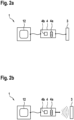
- Figure 2 shows two alternatives of the sensor system 1, where Figure 2a a first embodiment and Figure 2b represents a second embodiment of the sensor system 1.
- the sensor system 1 comprises a sound sensor 3 and a control unit 4.
- the sound sensor 3 is in particular a structure-borne sound sensor and can be attached to the pedal device 8 or to the frame 11 of the bicycle 2.
- the control unit 4 can optimally be attached to the frame 11 of the bicycle 2.
- the sensor system 1 can be coupled to an output device 12 in order to issue warnings and/or recommendations to the user of the bicycle 2.
- the output device 12 can in particular be a display and/or a loudspeaker and/or a haptic output and/or an interface to another terminal device, for example a smartphone.
- the control unit 4 has a memory 4a and an analysis unit 4b.
- the memory 4a serves to store predefined Sound signal data. Characteristic features can also be stored in the memory 4a as predefined sound signal data in order to reduce storage space requirements.
- the predefined sound signal data are sound signal data that can be detected by the sound sensor 3 when there is abnormal operation of the bicycle 2, in particular of the drive chain 5. This means that the control unit 4, in particular by means of the analysis unit 4b, compares the sound signals detected by the sound sensor 3 as sound signal data with the predefined sound signal data. If there is a match, the control unit 4 can detect abnormal operation of the drive chain 5.
- Abnormal operation of the drive chain 5 can be caused by various conditions.
- the drive chain 5 can have an unfavorable course between the rear sprocket cassette 7 and the front sprocket arrangement 9.
- the drive chain 5 can also have too high a degree of contamination or too low a degree of lubricant wetting. All of these conditions lead to characteristic noise emissions that can be detected by the sound sensor 3.
- the sound sensor 3 is designed in particular as a structure-borne sound sensor in order to minimize the recording of noise from the environment.
- the control unit 4 can therefore easily and with little effort record the corresponding characteristic sound signals of the drive chain 5.
- the sound sensor 3 can detect a deliberately induced abnormal state in which the emitted noises are detected during this abnormal operation.
- the associated sound signal data of the sound sensor 3 or at least characteristic features of this sound signal data are stored as predefined sound signal data in the memory 4a.
- This calibration process can be carried out once for an entire series of bicycles 2 in order to store the predefined sound signal data in all control units of the corresponding series.
- an individual calibration can also be carried out for each bicycle individually, and this can also be initiated in particular by the user himself.
- the sound sensor 3 is designed to be wired.
- the cable connection is preferably used both to transmit electrical energy and to transmit sound signal data.
- the sound sensor 3 it is possible for the sound sensor 3 to have its own energy supply, for example in the form of a battery, so that only sound signal data is transmitted via the cable connection between the control unit 4 and the sound sensor 3.
- the sound sensor 3 is designed to be wireless. Data transmission and/or energy transmission are advantageously wireless.
- the power supply to the sound sensor 3 by the control unit 4 is wireless.
- the sound sensor 3 has its own power supply, for example in the form of a battery.
- the signal transmission is in any case wireless.
- no complex cabling of the sound sensor 3 is necessary.
- the sound sensor 3 can thus be placed on the bicycle 2 simply and with little effort, whereby the sound sensor 3 is an autonomous element and can thus be attached in an optimal position for detecting the sound emission of the drive chain 5 without having to take any cabling into account.
- other design variants are also possible.
- the sound sensor 3 can be supplied with power in different ways, in particular by a battery and/or by a solar cell and/or by an existing vibration energy of the bicycle 2 and/or by a temperature difference between two metals and/or by other energy sources.
- the sound sensor 3 can also be coupled to the control unit 4, in particular by cable.
- Figure 3 shows schematically an abnormal operation of the drive chain 5 due to excessive inclination of the drive chain 5 between the front sprocket assembly 9 and the rear sprocket cassette 7.
- the drive chain 5 is mounted on a largest front sprocket 9a of the front sprocket arrangement 9 and a largest rear sprocket 7a of the rear sprocket cassette 7. This results in the drive chain 5 having a maximum inclination, since the front sprocket 9a used and the rear sprocket 7a used have a maximum distance 200 in the transverse direction 100 of the bicycle 2.
- the drive chain 5 Due to the large distance 200, the drive chain 5 is entangled between the front sprocket 9a and the rear sprocket 7a. Due to this entanglement, there is a large lateral load on the drive chain 5, which leads to increased wear on the drive chain 5. At the same time, a characteristic noise is emitted due to the entanglement.
- the sound sensor 3 of the sensor system 1 is advantageously attached to a hub 10 of the pedal device 8.
- the hub 10 is rigidly connected to the front sprocket arrangement 9, which promotes the propagation of structure-borne noise. This allows the sound sensor 3 to optimally record the sound emitted by the drive chain 5. At the same time, the recording of disturbing noises is minimized.
- control unit 4 compares the sound signal data of the sound sensor 3 with the predefined sound signal data stored in the memory 4a.
- the control unit 4 will determine that the sound recorded by the sound sensor 3 corresponds to a data set in the memory 4a, and the sound signal data of the sound sensor 3 thus corresponds to predefined sound signal data. The control unit 4 thus detects an abnormal state.
- the control unit 4 can either issue a warning via the output device 12 and/or can carry out an active gear change to reduce the distance 200. This can be done in particular by changing the front sprocket 9a and/or the rear sprocket 7a on which the drive chain 5 runs.
- the gear change does not change the gear ratio that the user of the bicycle has set. If this is not possible, the gear ratio is optimally changed as little as possible. The gear change therefore has no or almost no noticeable consequences for the user of the bicycle 2.
- recommendations for action are advantageously issued to the user. These include, for example, information on cleaning and/or maintenance of the drive chain 5.
- the sound sensor makes it easy and inexpensive to detect abnormal conditions of the drive chain 5.
- the sensor system 1 can thus provide information or take active action to eliminate an abnormal condition of the drive chain 5 as quickly as possible. This minimizes wear on the drive chain 5, which extends the service life of the drive chain 5 and in particular also of the sprocket cassette 7 and the sprocket arrangement 9.
Landscapes
- Engineering & Computer Science (AREA)
- Mechanical Engineering (AREA)
- Chemical & Material Sciences (AREA)
- Combustion & Propulsion (AREA)
- Transportation (AREA)
- Measurement Of Mechanical Vibrations Or Ultrasonic Waves (AREA)
Description
- Die vorliegende Erfindung betrifft ein Sensorsystem eines Fahrrads. Außerdem betrifft die Erfindung ein Fahrrad umfassend ein derartiges Sensorsystem. Mit dem Sensorsystem ist insbesondere ermöglicht, anormale Betriebszustände einer Antriebskette eines Fahrrads festzustellen.
- Aus dem Stand der Technik sind Fahrräder bekannt. Bei diesen werden üblicherweise Antriebsketten verwendet, um eine Kraft von einer von einem Benutzer zu bedienenden Pedalvorrichtung auf ein Hinterrad zu übertragen. Um ein Übersetzungsverhältnis zwischen Pedalvorrichtung und Hinterrad zu wählen, ist die Antriebskette üblicherweise auf verschiedene Zahnkränze schaltbar. Zumeist sind an dem Hinterrad und/oder an der Pedalvorrichtung mehrere Zahnkränze vorhanden, wobei vor allem an dem Hinterrad diese Zahnkränze zu einer Zahnkranzkassette zusammengefasst sind.
- Die Antriebskette kann jedoch einen anormalen Betrieb aufweisen, in dem die Antriebskette einem erhöhten Verschleiß unterliegt. Ein solcher Betrieb ist insbesondere dann gegeben, wenn zu hohe laterale Kräfte auf die Kette wirken. Dies ist gegeben, wenn die Antriebskette eine zu große Schrägstellung zwischen dem Zahnkranz an der Pedalvorrichtung und dem Zahnkranz an dem Hinterrad aufweist. In diesem Fall ist eine große Biegung vorhanden, die an den Stellen auftritt, an denen die Antriebskette die Zahnkränze verlässt. Eine solche Biegung führt zu einem erhöhten Verschleiß. Andere Fälle eines anormalen Betriebs sind insbesondere dann gegeben, wenn die Antriebskette verschmutzt ist oder ein Ölbenutzungsgrad der Antriebskette zu gering ist oder Zahnkränze abgenutzt sind.
- Als Beispiel wird in Dokument
DE 10 2011 077181 ein Sensorsystem offenbart, womit der Kettenzustand erkannt wird um einen anormalen Betrieb der Kette zu entdecken. - Das erfindungsgemäße Sensorsystem ermöglicht ein akustisches Überwachen der Antriebskette. Ein anormaler Betrieb der Antriebskette führt zu charakteristischen Geräuschemissionen. Diese können durch das Sensorsystem erfasst und zugeordnet werden. Somit ist eine Möglichkeit gegeben, anormale Betriebszustände der Antriebskette zu erfassen und einen Benutzer des Fahrrads gegebenenfalls zu warnen.
- Das erfindungsgemäße Sensorsystem eines Fahrrads umfasst einen Schallsensor sowie ein Steuergerät. Der Schallsensor ist ausgebildet, Schall von einer Antriebskette des Fahrrads aufzunehmen. Das Steuergerät ist eingerichtet, anhand eines Vergleichs von Schallsignalen Daten des Schallsensors mit vordefinierten Schallsignalen zwischen einem normalen Betrieb und einem anormalen Betrieb der Antriebskette zu unterscheiden. Wird die Antriebskette in dem anormalen Betrieb verwendet, so verschleißt die Antriebskette stärker als in dem Fall, wenn die Antriebskette in dem normalen Betrieb verwendet wird. Wird das Fahrrad über längere Zeit mit der Antriebskette in dem anormalen Betrieb benutzt, so ist ein erhöhter Verschleiß der Antriebskette zu erwarten. Es ist somit insbesondere vorgesehen, dass zumindest ein anormaler Betriebszustand, insbesondere eine Vielzahl von anormalen Betriebszuständen, charakterisiert und dem Steuergerät gespeichert sind. Das Steuergerät kann somit anhand des Schallsensors die anormalen Betriebszustände der Antriebskette erkennen. Anormale Betriebszustände sind stets mit einer charakteristischen Geräuschemission verbunden, die insbesondere das vermehrte Verschleißen der Antriebskette anzeigen. Somit kann anhand dieser Geräuschemission auf den anormalen Betrieb der Antriebskette rückgeschlossen werden. Der Schallsensor dient vorteilhafterweise zum Aufnehmen von Körperschall und ist besonders vorteilhaft als intelligenter Sensor ausgebildet. Somit lassen sich verschiedene Signalverarbeitungsschritte wie insbesondere eine Signalaufbereitung und/oder Signalverarbeitung und/oder Signalfilterung bereits in dem Schallsensor ausführen.
- Es ist vorgesehen, dass die vordefinierten Schallsignaldaten solche Schallsignaldaten umfassen, die mittels des Schallsensors bei anormalem Betrieb der Antriebskette aufgenommen wurden. Dies bedeutet, dass gezielt anormale Betriebszustände der Antriebskette vorgesehen werden, wobei der durch diesen anormalen Betrieb erzeugte Schall von dem Schallsensor aufgenommen wird. Es werden charakteristische Merkmale solcher Schallsignaldaten verwendet, die mittels des Schallsensors bei anormalem Betrieb aufgenommen wurden. Bei solchen charakteristischen Merkmalen handelt es sich um Mel-Frequenz-Cepstrum-Koeffizienten. Somit ist ermöglicht, dass einmalig anormale Betriebszustände charakterisiert werden, wobei in dem Steuergerät die gespeicherten Schallsignaldaten oder die charakteristischen Merkmale der Schallsignaldaten für eine Vielzahl von Sensorsystemen verwendet werden kann. Damit lässt sich das Sensorsystem auf einfache Art und Weise trainieren. Ebenso lässt sich die Möglichkeit des Sensorsystems, anormale Betriebszustände zu erkennen, erweitern, indem neue Schallsignaldaten oder charakteristische Merkmale von Schallsignaldaten von weiteren anormalen Betriebszuständen hinzugefügt werden.
- Die Unteransprüche haben bevorzugte Weiterbildungen der Erfindung zum Inhalt.
- Bevorzugt ist vorgesehen, dass in dem Steuergerät eine Vielzahl von vordefinierten Schallsignaldaten gespeichert ist. Jeder vordefinierte Signaldatensatz charakterisiert dabei bevorzugt einen spezifischen anormalen Betriebszustand. Es ist vorgesehen, dass mehrere Sätze dieser vordefinierten Schallsignaldaten in einer Datenbank und/oder Look-Up-Tabelle gespeichert sind, wobei jeder Satz vordefinierter Schallsignaldaten einem unterschiedlichen anormalen Betriebszustand der Antriebskette entspricht. Auf diese Weise ist ein Charakterisieren des anormalen Betriebs ermöglicht. Es ist dazu lediglich notwendig, die von dem Schallsensor ermittelten Schallsignaldaten mit den in der Datenbank oder der Look-Up-Tabelle gespeicherten Schallsignaldaten zu vergleichen. Anhand eines solchen Vergleichs lässt sich derjenige Umstand identifizieren, der zu dem anormalen Betrieb der Antriebskette führt. Dem Benutzer des Fahrrads kann damit eine zielgerichtete Warnung und/oder Empfehlung ausgegeben werden, die auf den genauen Umstand der Antriebskette hinweist, die zu dem anormalen Betrieb führt. Insbesondere lassen sich auch solche Fälle erfassen, bei denen sich mehrere anormale Betriebszustände überlagern. Dies ist insbesondere derart möglich, dass für spezifische Kombinationen von anormalen Betriebszuständen charakteristische Schallsignaldaten vordefinierten und gespeichert sind. Somit kann direkt erkannt werden, ob mehrere anormale Betriebszustände gleichzeitig vorliegen. Auch kann mittels Signalverarbeitung aus dem Schallsignal des Schallsensors die charakteristischen Schallsignaldaten ausgefiltert werden, um die überlagerten anormalen Betriebszustände zu erkennen. Während die erstere Methode lediglich geringen Rechenaufwand, dafür aber einen größeren Speicher zum Speichern einer größeren Anzahl von vordefinierten Schallsignaldaten benötigt, ist für die letztere Methode ein kleinerer Speicher, dafür aber ein erhöhter Rechenaufwand zur Filterung des Schallsignals des Schallsensors notwendig.
- Der Schallsensor kann vorteilhafterweise eine kabelgebundene oder alternativ eine kabellose Verbindung mit dem Steuergerät zur Datenübertragung und/oder Energieversorgung aufweisen. Der Schallsensor kann insbesondere eine autarke Energieversorgung aufweisen, indem der Schallsensor insbesondere mit einer eigenen Batterie versehen ist. Alternativ kann eine Energieversorgung auch kabellos über das Steuergerät erfolgen, wie dies aus dem Stand der Technik, beispielsweise für RFID-Systeme, bekannt ist. Gleiches gilt für die Datenübertragung. Auch hier kann insbesondere eine Funk-Signaldatenübertragung erfolgen. Besonders vorteilhaft ist sowohl die Datenübertragung als auch die Energieversorgung kabellos ausgebildet, so dass der Schallsensor als autarkes Element an einer unterschiedlichen Position bezüglich des Steuergeräts angebracht werden kann. Somit ist ein einfacher Aufbau und ein wartungsfreier Betrieb des Sensorsystems ermöglicht.
- Der Schallsensor ist insbesondere ein Körperschallsensor. Der Körperschallsensor lässt sich optimaler Weise in der Nähe der Schallquelle, d.h. der Antriebskette, anbringen. Durch die Verwendung eines Körperschallsensors sind insbesondere Aufnahmen von Störgeräuschen aus der Umgebung, wie dies bei einem Luftschallsensor der Fall wäre, vermieden. Somit ist eine Signalverarbeitung von Signalen des Schallsensors vereinfacht. Damit lassen sich anormalen Betriebszustände der Antriebskette einfach und aufwandsarm, dabei gleichzeitig aber sehr zuverlässig, ermitteln.
- Die Erfindung betrifft außerdem ein Fahrrad. Das Fahrrad umfasst ein Sensorsystem wie zuvor beschrieben. Dabei ist vorgesehen, dass der Schallsensor des Sensorsystems an einer Pedalvorrichtung des Fahrrads angebracht ist. Insbesondere ist der Schallsensor vorteilhafterweise an einer Nabe der Pedalvorrichtung angebracht. Die Pedalvorrichtung umfasst dabei zumeist zwei Pedale, die von dem Benutzer des Fahrrads zu betätigen sind, um das Fahrrad anzutreiben. In einer alternativen Ausgestaltung kann der Schallsensor auch an einem Rahmen des Fahrrads angebracht sein. Besonders vorteilhaft ist vorgesehen, dass der Schallsensor an einem Element des Fahrrads angebracht ist, das fest mit einem Zahnkranz, in dem die Antriebskette läuft, gekoppelt ist. In diesem Fall ist ermöglicht, dass Geräusche der Antriebskette sicher und zuverlässig aufgenommen werden können.
- Das Fahrrad weist bevorzugt zumindest einen hinteren Zahnkranz auf, der an einem Hinterrad des Fahrrads angebracht ist. Der hintere Zahnkranz ist bevorzugt Teil einer Zahnkranzkassette. Alternativ oder zusätzlich weist das Fahrrad bevorzugt zumindest einen vorderen Zahnkranz auf, der an einer Pedalvorrichtung angebracht ist. Der vordere Zahnkranz ist insbesondere Teil einer Zahnkranzanordnung. Die Antriebskette verläuft zwischen dem einem der hinteren Zahnkränze und einem der vorderen Zahnkränze. Anstatt mehrerer hinterer Zahnkränze bzw. einer Zahnkranzkassette oder anstatt mehrerer vorderer Zahnkränze kann insbesondere auch ein einzelner, singulärer Zahnkranz vorgesehen sein. Sind mehrere Zahnkränze vorhanden, so ist vorgesehen, dass die Antriebskette zwischen einem hinteren Zahnkranz der hinteren Zahnkranzkassette und einem vorderen Zahnkranz der mehreren vorderen Zahnkränze verläuft. Der anormale Betrieb der Antriebskette entspricht in diesem Fall einem Zustand der Antriebskette, bei dem die Antriebskette zwischen einem solchen vorderen Zahnkranz und einem solchen hinteren Zahnkranz verläuft, die einen Abstand in Querrichtung des Fahrrads aufweisen, der oberhalb eines vordefinierten Grenzwerts liegt. Somit verläuft die Antriebskette in Längsrichtung des Fahrrads nicht entlang einer Geraden, sondern ist zwischen dem vorderen Zahnkranz und dem hinteren Zahnkranz verschränkt, sodass die Antriebskette zwischen dem vorderen Zahnkranz und dem hinteren Zahnkranz schräg zur Querrichtung verläuft. Ist diese Schrägstellung zu groß, d.h. ist der Abstand zwischen dem für die Antriebskette verwendeten vorderen Zahnkranz und hinteren Zahnkranz in Querrichtung des Fahrrads zu groß, so tritt der anormale Betrieb auf. Dies lässt sich, wie zuvor beschrieben, anhand des charakteristischen Geräuschs der Antriebskette in einem solchen Zustand durch den Schallsensor detektieren.
- Das Steuergerät ist vorteilhafterweise eingerichtet, einen Schalteingriff vorzunehmen, um die Antriebskette auf einen solchen vorderen Zahnkranz und/oder auf einen solchen hinteren Zahnkranz zu überführen, so dass der Abstand in Querrichtung verringert ist. Dies bedeutet, dass der anormale Betrieb der Antriebskette des Fahrrads durch einen aktiven Schalteingriff des Steuergeräts beendet werden kann. Optimalerweise wird dabei ein Übersetzungsverhältnis zwischen vorderem Zahnkranz und hinterem Zahnkranz gewählt, das dem von dem Benutzer gewünschten Übersetzungsverhältnis entspricht. Somit ist der Schalteingriff für den Benutzer nahezu nicht wahrnehmbar.
- Bevorzugt ist weiterhin vorgesehen, dass der anormale Betrieb einen Zustand der Antriebskette umfasst, bei dem ein Schmiermittelbenutzungsgrad der Antriebskette unterhalb eines vordefinierten Grads liegt. Auch ist vorgesehen, dass der anormale Betrieb einen Zustand der Antriebskette umfasst, bei dem die Antriebskette einen Verschmutzungsgrad aufweist, der oberhalb eines vordefinierten Grads liegt. Wird die Antriebskette in diesen Fällen betrieben, so verschleißt die Antriebskette vermehrt im Vergleich zu dem Fall einer nicht verschmutzten und/oder korrekt geschmierten Antriebskette. Weiterhin weisen solche Fälle Schallemissionen auf, die charakteristisch für den jeweiligen Zustand der Antriebskette sind. Somit lässt sich auch jeder dieser beschriebenen anormalen Betriebszustände der Antriebskette durch das Sensorsystem erkennen, so dass eine entsprechende Warnung an den Benutzer des Fahrrads ausgegeben werden kann.
- Das Fahrrad weist in einer weiteren bevorzugten Ausführungsform eine Ausgabevorrichtung auf. Das Steuergerät ist bevorzugt eingerichtet, eine optische und/oder haptische und/oder akustische Warnung auszugeben, wenn ein anormaler Betrieb detektiert ist. Besonders bevorzugt werden außerdem Handlungsempfehlungen ausgegeben, die den Benutzer veranlassen sollen, eine gewisse Handlung auszuführen. Dies kann insbesondere eine Schaltempfehlung und/oder ein Hinweis sein, dass die Antriebskette gereinigt oder geschmiert werden sollte. Bei der Ausgabevorrichtung kann es sich bevorzugt um eine Displayanzeige handeln. Ebenso kann es sich bei der Ausgabevorrichtung um eine Schnittstelle zu einem externen Gerät, insbesondere zu einem Smartphone, handeln.
- Nachfolgend werden Ausführungsbeispiele der Erfindung unter Bezugnahme auf die begleitende Zeichnung im Detail beschrieben. In der Zeichnung ist:
- Figur 1
- eine schematische Ansicht eines Fahrrads gemäß einem Ausführungsbeispiel der Erfindung,
- Figur 2a
- eine schematische Darstellung eines Sensorsystems gemäß einem ersten Ausführungsbeispiel der Erfindung,
- Figur 2b
- eine schematische Darstellung eines Sensorsystems gemäß einem zweiten Ausführungsbeispiel der Erfindung, und
- Figur 3
- eine schematische Darstellung eines anormalen Betriebs einer Antriebskette des Fahrrads gemäß dem Ausführungsbeispiel der Erfindung.
-
Figur 1 zeigt schematisch ein Fahrrad 2 gemäß einem Ausführungsbeispiel der Erfindung. - Das Fahrrad 2 umfasst eine Pedalvorrichtung 8 mit einer vorderen Zahnkranzanordnung 9, die mehrere Zahnkränze aufweist. Außerdem umfasst das Fahrrad 2 ein Hinterrad 6 mit einer hinteren Zahnkranzkassette 7, die ebenfalls mehrere Zahnkränze aufweist. Über einen Rahmen 11 sind Hinterrad 6 und Pedalvorrichtung 8 gekoppelt. Eine Antriebskette 5 verläuft zwischen einem hinteren Zahnkranz 7a der hinteren Zahnkranzkassette 7 und einem vorderen Zahnkranz 9a der vorderen Zahnkranzanordnung 9. Diese Antriebskette 5 dient zur Kraftübertragung zwischen der Pedalvorrichtung 8 und dem Hinterrad 6 und dient somit zur Kraftübertragung der Muskelkraft des Benutzers des Fahrrads 2 auf das Hinterrad 6.
- In einem normalen Betrieb ist ein Verschleiß der Antriebskette 5 minimiert. Allerdings können anormale Betriebszustände auftreten, bei denen die Antriebskette 5 vermehrt verschleißt. Wird die Antriebskette 5 über längere Zeiträume in dem anormalen Betriebszustand verwendet, so ist gegenüber demselben Zeitraum mit normalem Betriebszustand der Antriebskette 5 mit einem höheren Verschleiß zu rechnen. Um solche anormale Betriebszustände zu erkennen, weist das Fahrrad 2 ein Sensorsystem 1 wie in
Figur 2 gezeigt auf. -
Figur 2 zeigt zwei Alternativen des Sensorsystems 1, wobeiFigur 2a eine erste Ausführungsform undFigur 2b eine zweite Ausführungsform des Sensorsystems 1 darstellt. Das Sensorsystem 1 umfasst in beiden Ausführungsbeispielen einen Schallsensor 3 und ein Steuergerät 4. Der Schallsensor 3 ist insbesondere ein Körperschallsensor und kann an der Pedalvorrichtung 8 oder an dem Rahmen 11 des Fahrrads 2 angebracht werden. Das Steuergerät 4 ist optimalerweise an dem Rahmen 11 des Fahrrads 2 anbringbar. Außerdem ist das Sensorsystem 1 mit einer Ausgabevorrichtung 12 koppelbar, um Warnungen und/oder Empfehlungen an den Benutzer des Fahrrads 2 auszugeben. Bei der Ausgabevorrichtung 12 kann es sich insbesondere um ein Display und/oder um einen Lautsprecher und/oder um eine haptische Ausgabe und/oder um eine Schnittstelle zu einem weiteren Endgerät, beispielsweise einem Smartphone, handeln. - In beiden Ausführungsbeispielen weist das Steuergerät 4 einen Speicher 4a und eine Analyseeinheit 4b auf. Der Speicher 4a dient zum Speichern vordefinierter Schallsignaldaten. Ebenso können in dem Speicher 4a charakteristische Merkmal als vordefinierte Schallsignaldaten gespeichert werden, um einen Speicherplatzbedarf zu reduzieren. Bei den vordefinierten Schallsignaldaten handelt es sich um solche Schallsignaldaten, die mit dem Schallsensor 3 erfassbar sind, wenn ein anormaler Betrieb des Fahrrads 2, insbesondere der Antriebskette 5, vorliegt. Dies bedeutet, dass das Steuergerät 4, insbesondere mittels der Analyseeinheit 4b, die von dem Schallsensor 3 erfassten Schallsignale als Schallsignaldaten mit den vordefinierten Schallsignaldaten vergleicht. Ist eine Übereinstimmung vorhanden, so kann das Steuergerät 4 einen anormalen Betrieb der Antriebskette 5 erkennen.
- Ein anormaler Betrieb der Antriebskette 5 kann durch verschiedene Zustände erreicht werden. So kann die Antriebskette 5 einen ungünstigen Verlauf zwischen der hinteren Zahnkranzkassette 7 und der vorderen Zahnkranzanordnung 9 aufweisen. Ebenso kann die Antriebskette 5 einen zu hohen Verschmutzungsgrad oder einen zu geringen Schmiermittelbenetzungsgrad aufweisen. Alle diese Zustände führen zu charakteristischen Geräuschemissionen, die von dem Schallsensor 3 erfassbar sind. Der Schallsensor 3 ist insbesondere als Körperschallsensor ausgebildet, um die Aufnahme von Störgeräuschen aus der Umgebung zu minimieren. Somit kann das Steuergerät 4 einfach und aufwandsarm die entsprechenden charakteristischen Schallsignale der Antriebskette 5 erfassen.
- Um die vordefinierten Schallsignale in dem Speicher 4a zu speichern, ist insbesondere vorgesehen, dass eine einmalige Kalibrierung ausgeführt wird. Bei dieser kann der Schallsensor 3 einen bewusst herbeigeführten anormalen Zustand erfassen, in dem die emittierten Geräusche während dieses anormalen Betriebs erfasst werden. In dem Steuergerät 4 werden die zugehörigen Schallsignaldaten des Schallsensors 3 oder zumindest charakteristische Merkmale dieser Schallsignaldaten als vordefinierte Schallsignaldaten in dem Speicher 4a gespeichert. Dieser Kalibrierungsprozess kann einmalig für eine ganze Baureihe von Fahrrädern 2 vorgenommen werden, um die vordefinierten Schallsignaldaten in allen Steuergeräten der entsprechenden Baureihe zu speichern. Ebenso kann aber auch eine individuelle Kalibrierung für jedes Fahrrad einzeln vorgenommen werden, wobei dies insbesondere auch durch den Benutzer selbst initiiert werden kann.
- In dem in
Figur 2a gezeigten ersten Ausführungsbeispiel ist der Schallsensor 3 kabelgebunden ausgebildet. Somit ist eine Kabelverbindung zwischen Steuergerät 4 und Schallsensor 3 vorhanden. Die Kabelverbindung dient bevorzugt sowohl zum Übertragen von elektrischer Energie als auch zum Übertragen von Schallsignaldaten. Alternativ besteht die Möglichkeit, dass der Schallsensor 3 eine eigene Energieversorgung, beispielsweise in Form einer Batterie, aufweist, so dass lediglich Schallsignaldaten über die Kabelverbindung zwischen Steuergerät 4 und Schallsensor 3 zu übertragen sind. - In dem in
Figur 2b gezeigten zweiten Ausführungsbeispiel ist der Schallsensor 3 kabellos ausgebildet. Eine Datenübertragung und/oder eine Energieübertragung erfolgen vorteilhafterweise kabellos. So ist insbesondere vorgesehen, dass eine Energieversorgung des Schallsensors 3 durch das Steuergerät 4 kabellos erfolgt. Dies ist insbesondere für RFID-Systeme aus dem Stand der Technik bekannt. Alternativ weist der Schallsensor 3 eine eigene Energieversorgung auf, beispielsweise in Form einer Batterie. Die Signalübertragung ist in jedem Fall kabellos vorgesehen. Somit ist in dem zweiten Ausführungsbeispiel keine aufwendige Verkabelung des Schallsensors 3 notwendig. Der Schallsensor 3 kann somit einfach und aufwandsarm an dem Fahrrad 2 platziert werden, wobei der Schallsensor 3 ein autarkes Element ist und somit an einer optimalen Position zum Erfassen der Schallemission der Antriebskette 5 angebracht werden kann, ohne dass Rücksicht auf eine evtl. Verkabelung genommen werden muss. Es sind aber auch andere Ausführungsvarianten möglich. So kann eine Stromversorgung des Schallsensors 3 auf unterschiedliche Arten erfolgen, insbesondere durch eine Batterie und/oder durch eine Solarzelle und/oder durch eine vorhandene Vibrationsenergie des Fahrrads 2 und/oder durch eine Temperaturdifferenz zweier Metalle und/oder durch andere Energiequellen. Auch kann der Schallsensor 3 insbesondere kabelgebunden an das Steuergerät 4 gekoppelt sein. -
Figur 3 zeigt schematisch einen anormalen Betrieb der Antriebskette 5 aufgrund zu großer Schrägstellung der Antriebskette 5 zwischen der vorderen Zahnkranzanordnung 9 und der hinteren Zahnkranzkassette 7. So ist inFigur 3 beispielhaft gezeigt, dass die Antriebskette 5 jeweils auf einem größten vorderen Zahnkranz 9a der vorderen Zahnkranzanordnung 9 und einem größten hinteren Zahnkranz 7a der hinteren Zahnkranzkassette 7 angebracht ist. Dies führt dazu, dass die Antriebskette 5 eine maximale Schrägstellung aufweist, da der verwendete vordere Zahnkranz 9a und der verwendete hintere Zahnkranz 7a einen maximalen Abstand 200 in Querrichtung 100 des Fahrrads 2 aufweisen. - Es ist vorgesehen, dass ein maximaler Abstand in Querrichtung 100 vordefiniert ist, wobei der anormale Betrieb dann erkannt wird, wenn der tatsächliche Abstand 200 den maximalen Abstand überschreitet. Dieser Fall ist in
Figur 3 gegeben. - Aufgrund des großen Abstands 200 ist die Antriebskette 5 zwischen dem vorderen Zahnkranz 9a und an dem hinteren Zahnkranz 7a verschränkt. Aufgrund dieser Verschränkung ist eine große laterale Belastung der Antriebskette 5 vorhanden, die dazu führt, dass die Antriebskette 5 vermehrt verschleißt. Gleichzeitig wird aufgrund der Verschränkung ein charakteristisches Geräusch emittiert.
- Der Schallsensor 3 des Sensorsystems 1 ist vorteilhaftweise an einer Nabe 10 der Pedalvorrichtung 8 angebracht. Die Nabe 10 ist steif mit der vorderen Zahnkranzanordnung 9 verbunden, was eine Körperschallausbreitung begünstigt. Somit kann der Schallsensor 3 optimal den Schall aufnehmen, der von der Antriebskette 5 emittiert wird. Eine Aufnahme von Störgeräuschen ist gleichzeitig minimiert.
- Es ist vorgesehen, dass das Steuergerät 4 die Schallsignaldaten des Schallsensors 3 mit den in dem Speicher 4a gespeicherten vordefinierten Schallsignaldaten vergleicht. In dem in
Figur 3 gezeigten Fall wird das Steuergerät 4 feststellen, dass das Geräusch, das von dem Schallsensor 3 aufgenommen wurde, einem Datensatz in dem Speicher 4a entspricht, die Schallsignaldaten des Schallsensors 3 somit mit vordefinierten Schallsignaldaten übereinstimmen. Somit erkennt das Steuergerät 4 einen anormalen Zustand. - Das Steuergerät 4 kann entweder eine Warnung über die Ausgabevorrichtung 12 ausgeben und/oder kann einen aktiven Schalteingriff vornehmen, um den Abstand 200 zu verringern. Dies kann insbesondere durch eine Veränderung des vorderen Zahnkranzes 9a und/oder des hinteren Zahnkranzes 7a, auf dem die Antriebskette 5 verläuft, geschehen. Vorteilhafterweise wird durch den Schalteingriff nicht das Übersetzungsverhältnis geändert, das der Benutzer des Fahrrads eingestellt hat. Sollte dies nicht möglich sein, so wird das Übersetzungsverhältnis optimalerweise nur so gering wie möglich verändert. Somit hat der Schalteingriff für den Benutzer des Fahrrads 2 keine oder nahezu keine merklichen Folgen.
- Sollte ein anormaler Betrieb durch einen zu großen Verschmutzungsgrad der Antriebskette 5 und/oder durch einen zu geringen Schmiermittelbenutzungsgrad der Antriebskette 5 erkannt werden, so werden vorteilhafterweise Handlungsempfehlungen an den Benutzer ausgegeben. Diese umfassen beispielsweise den Hinweis auf einer durchzuführenden Reinigung und/oder Wartung der Antriebskette 5.
- Durch den Schallsensor ist einfach und aufwandsarm ermöglicht, anormale Zustände der Antriebskette 5 zu erkennen. Durch das Sensorsystem 1 lassen sich somit Hinweise oder aktive Eingriffe vornehmen, um einen anormalen Zustand der Antriebskette 5 schnellstmöglich zu beseitigen. Somit ist ein Verschleiß der Antriebskette 5 minimiert, wodurch die Lebensdauer der Antriebskette 5 und insbesondere auch der Zahnkranzkassette 7 und der Zahnkranzanordnung 9 verlängert ist.
Claims (9)
- Sensorsystem (1) eines Fahrrads (2), umfassend einen Schallsensor (3) sowie ein Steuergerät (4), wobei der Schallsensor (3) ausgebildet ist, Schall von einer Antriebskette (5) des Fahrrads (2) aufzunehmen, und wobei das Steuergerät (4) eingerichtet ist, anhand eines Vergleichs von Schallsignaldaten des Schallsensors (3) mit vordefinierten Schallsignaldaten zwischen einem normalen Betrieb der Antriebskette (5) und einem anormalen Betrieb der Antriebskette (5), bei dem die Antriebskette (5) einem erhöhten Verschleiß unterliegt, zu unterscheiden, wobei die vordefinierten Schallsignaldaten zumindest ein charakteristisches Merkmal solcher Schallsignaldaten umfassen, die mittels des Schallsensors (3) bei anormalem Betrieb der Antriebskette (5) aufgenommen wurden, wobei die charakteristischen Merkmale Mel-Frequenz-Cepstrum-Koeffizienten sind.
- Sensorsystem (1) eines Fahrrads (2) nach Anspruch 1, dadurch gekennzeichnet, dass in dem Steuergerät (4) mehrere Sätze vordefinierter Schallsignaldaten in einer Datenbank und/oder Look-Up-Tabelle gespeichert sind, wobei jeder Satz vordefinierter Schallsignaldaten einem unterschiedlichen Zustand der Antriebskette (5) entspricht, der zu einem anormalen Betrieb führt.
- Sensorsystem (1) eines Fahrrads (2) nach einem der vorhergehenden Ansprüche, dadurch gekennzeichnet, dass der Schallsensor (3) eine kabelgebundene oder eine kabellose Verbindung mit dem Steuergerät (4) zur Datenübertragung und/oder Energieversorgung aufweist.
- Sensorsystem (1) eines Fahrrads (2) nach einem der vorhergehenden Ansprüche, dadurch gekennzeichnet, dass der Schallsensor (3) ein Körperschallsensor ist.
- Fahrrad (2) umfassend ein Sensorsystem (1) nach einem der vorhergehenden Ansprüche, wobei der Schallsensor (2) an einer Pedalvorrichtung (8), insbesondere an einer Nabe (10) der Pedalvorrichtung (8), oder an einem Rahmen (11) des Fahrrads (2) angebracht ist.
- Fahrrad (2) nach Anspruch 5, gekennzeichnet durch eine an einem Hinterrad (6) des Fahrrads angeordnete hintere Zahnkranzkassette (7) mit zumindest einem Zahnkranz (7a) und/oder einer an einer Pedalvorrichtung (8) angeordnete vorderen Zahnkranzanordnung (9) mit zumindest einem Zahnkranz (9a), wobei die Antriebskette (5) zwischen einem hinteren Zahnkranz (7a) der hinteren Zahnkranzkassette (7) und einem vorderen Zahnkranz (9a) der vorderen Zahnkranzanordnung (9) verläuft, und wobei der anormale Betrieb einen Zustand der Antriebskette (5) umfasst, bei dem die Antriebskette (5) zwischen einem solchen vorderen Zahnkranz (9a) und einem solchen hinterem Zahnkranz (7a) verläuft, die einen Abstand (200) in Querrichtung (100) des Fahrrads (2) aufweisen, der oberhalb eines vordefinierten Grenzwerts liegt.
- Fahrrad (2) nach Anspruch 6, dadurch gekennzeichnet, dass das Steuergerät (4) eingerichtet ist, einen Schalteingriff vorzunehmen, um die Antriebskette (5) auf einen solchen vorderen Zahnkranz (9a) und/oder hinteren Zahnkranz (7a) zu überführen, sodass der Abstand (200) in Querrichtung (100) verringert ist.
- Fahrrad (2) nach einem der Ansprüche 5 bis 7, dadurch gekennzeichnet, dass der anormale Betrieb einen Zustand der Antriebskette (5) umfasst, bei dem eine Schmiermittelbenetzung der Antriebskette (5) unterhalb eines vordefinierten Grads und/oder eine Verschmutzung der Antriebskette (5) oberhalb eines vordefinierten Grads liegt.
- Fahrrad (2) nach einem der Ansprüche 5 bis 8, gekennzeichnet durch eine Ausgabevorrichtung (12), wobei das Steuergerät (4) eingerichtet ist, eine optische und/oder haptische und/oder akustische Warnung auszugeben, wenn ein anormaler Betrieb detektiert ist.
Applications Claiming Priority (1)
| Application Number | Priority Date | Filing Date | Title |
|---|---|---|---|
| DE102018211729.2A DE102018211729B4 (de) | 2018-07-13 | 2018-07-13 | Sensorsystem eines Fahrrads |
Publications (3)
| Publication Number | Publication Date |
|---|---|
| EP3594531A1 EP3594531A1 (de) | 2020-01-15 |
| EP3594531B1 EP3594531B1 (de) | 2021-06-09 |
| EP3594531B2 true EP3594531B2 (de) | 2024-08-07 |
Family
ID=67314578
Family Applications (1)
| Application Number | Title | Priority Date | Filing Date |
|---|---|---|---|
| EP19182468.9A Active EP3594531B2 (de) | 2018-07-13 | 2019-06-26 | Sensorsystem des kettenzustands eines fahrrads |
Country Status (2)
| Country | Link |
|---|---|
| EP (1) | EP3594531B2 (de) |
| DE (1) | DE102018211729B4 (de) |
Families Citing this family (2)
| Publication number | Priority date | Publication date | Assignee | Title |
|---|---|---|---|---|
| DE102020210904A1 (de) | 2020-08-28 | 2022-03-03 | Robert Bosch Gesellschaft mit beschränkter Haftung | Verfahren und Vorrichtung zum Überwachen eines Zustands einer Hubkette eines Hubarbeitswerkzeugs und Hubarbeitswerkzeug |
| DE102023200215A1 (de) | 2023-01-12 | 2024-07-18 | Robert Bosch Gesellschaft mit beschränkter Haftung | Vorrichtung zur Schmierung einer Kette eines Fahrzeugs |
Citations (7)
| Publication number | Priority date | Publication date | Assignee | Title |
|---|---|---|---|---|
| DE19826220A1 (de) † | 1998-06-09 | 1999-12-23 | Tamas Diebel | Vorrichtung zur Erkennung von Fahrwerkschäden an Schienenfahrzeugen während der Fahrt |
| US7100742B2 (en) † | 2000-08-11 | 2006-09-05 | Hy-Power Flexomatic Hydraulik Handelsges M.B.H. | Method for controlling the delivery of lubricant |
| DE102007051261A1 (de) † | 2007-10-26 | 2009-04-30 | Volkswagen Ag | Verfahren und Vorrichtung zur akustischen Beurteilung eines Kraftfahrzeuges |
| US20140123760A1 (en) † | 2012-11-07 | 2014-05-08 | Siemens Aktiengesellschaft | Apparatus and method for monitoring the state of a roller bearing |
| US20160288877A1 (en) † | 2015-04-01 | 2016-10-06 | Wick Werks, LLC | Bicycle derailleur with automatic alignment, and methods for automatic derailleur alignment |
| US9514576B2 (en) † | 2011-06-08 | 2016-12-06 | Robert Bosch Gmbh | Method and device for detecting wear on an electric bicycle |
| CN206288131U (zh) † | 2016-12-19 | 2017-06-30 | 北京拜克洛克科技有限公司 | 一种智能单车及智能单车故障检测系统 |
Family Cites Families (6)
| Publication number | Priority date | Publication date | Assignee | Title |
|---|---|---|---|---|
| US6367833B1 (en) | 2000-09-13 | 2002-04-09 | Shimano, Inc. | Automatic shifting control device for a bicycle |
| CN202557683U (zh) * | 2012-05-15 | 2012-11-28 | 张华麟 | 电动自行车链条润滑控制器 |
| ITMI20121279A1 (it) | 2012-07-23 | 2014-01-24 | Campagnolo Srl | Metodo per controllare elettronicamente un cambio di bicicletta e cambio di bicicletta servoassistito elettronicamente |
| US9221618B2 (en) * | 2012-11-06 | 2015-12-29 | AMF automation Technologies, LLC | Oven chain measurement system |
| DE102015120590A1 (de) * | 2015-11-27 | 2017-06-01 | Deutsche Telekom Ag | Sensorsystem zur Montage an einem Fahrrad |
| DE102015016263A1 (de) * | 2015-12-15 | 2017-06-22 | Sram Deutschland Gmbh | Kettenring |
-
2018
- 2018-07-13 DE DE102018211729.2A patent/DE102018211729B4/de not_active Expired - Fee Related
-
2019
- 2019-06-26 EP EP19182468.9A patent/EP3594531B2/de active Active
Patent Citations (7)
| Publication number | Priority date | Publication date | Assignee | Title |
|---|---|---|---|---|
| DE19826220A1 (de) † | 1998-06-09 | 1999-12-23 | Tamas Diebel | Vorrichtung zur Erkennung von Fahrwerkschäden an Schienenfahrzeugen während der Fahrt |
| US7100742B2 (en) † | 2000-08-11 | 2006-09-05 | Hy-Power Flexomatic Hydraulik Handelsges M.B.H. | Method for controlling the delivery of lubricant |
| DE102007051261A1 (de) † | 2007-10-26 | 2009-04-30 | Volkswagen Ag | Verfahren und Vorrichtung zur akustischen Beurteilung eines Kraftfahrzeuges |
| US9514576B2 (en) † | 2011-06-08 | 2016-12-06 | Robert Bosch Gmbh | Method and device for detecting wear on an electric bicycle |
| US20140123760A1 (en) † | 2012-11-07 | 2014-05-08 | Siemens Aktiengesellschaft | Apparatus and method for monitoring the state of a roller bearing |
| US20160288877A1 (en) † | 2015-04-01 | 2016-10-06 | Wick Werks, LLC | Bicycle derailleur with automatic alignment, and methods for automatic derailleur alignment |
| CN206288131U (zh) † | 2016-12-19 | 2017-06-30 | 北京拜克洛克科技有限公司 | 一种智能单车及智能单车故障检测系统 |
Non-Patent Citations (6)
| Title |
|---|
| DA FONSECA CACADOR FILIPE MANUEL: "Bicycle drivetrain noise and vibration test development", THESIS, 1 July 2016 (2016-07-01), pages 1 - 75, XP055903947 † |
| DELVECCHIO S.; BONFIGLIO P.; POMPOLI F.: "Vibro-acoustic condition monitoring of Internal Combustion Engines: A critical review of existing techniques", MECHANICAL SYSTEMS AND SIGNAL PROCESSING, ELSEVIER, AMSTERDAM, NL, vol. 99, 1 January 1900 (1900-01-01), AMSTERDAM, NL, pages 661 - 683, XP085152107, ISSN: 0888-3270, DOI: 10.1016/j.ymssp.2017.06.033 † |
| JONES C CALVIN: "Big Blue Book of Bicycle Repair", PARK TOOL COMPANY, 1 January 2005 (2005-01-01), pages 1 - 9, XP055903874 † |
| ROBERTO PALAZZETTI, YAN XIU-TIAN: "Study on lubrication effect on motorbike chain transmissions", INDUSTRIAL LUBRICATION AND TRIBOLOGY, PETERSON PUBLISHING, DROITWICH, GB, vol. 68, no. 5, 8 August 2016 (2016-08-08), GB, pages 561 - 568, XP055436249, ISSN: 0036-8792, DOI: 10.1108/ILT-10-2015-0142 † |
| SEPPANEN ALEKSI: "Utilizing acoustic measurements in equipment condition monitoring", THESIS, 23 May 2016 (2016-05-23), pages 1 - 74, XP055903933 † |
| SOPOUCH MARTIN, HELLINGER W., PRIEBSCH H. H.: "Prediction of vibroacoustic excitation due to the timing chains of reciprocating engines", PROCEEDINGS OF THE INSTITUTION OF MECHANICAL ENGINEERS, PART K: JOURNAL OF MULTI-BODY DYNAMICS, vol. 217, no. 3, 1 September 2003 (2003-09-01), pages 225 - 240, XP055903954 † |
Also Published As
| Publication number | Publication date |
|---|---|
| DE102018211729A1 (de) | 2020-01-16 |
| DE102018211729B4 (de) | 2020-04-02 |
| EP3594531A1 (de) | 2020-01-15 |
| EP3594531B1 (de) | 2021-06-09 |
Similar Documents
| Publication | Publication Date | Title |
|---|---|---|
| EP3271229B1 (de) | Verfahren zum betreiben eines kraftfahrzeugs und zugehöriges kraftfahrzeug | |
| EP4000018A1 (de) | Vorausschauende wartung für eine vorrichtung in der lebensmittelindustrie mithilfe eines digitalen zwillings und optimierte produktionsplanung | |
| EP3088235B1 (de) | Energiemanagementsystem für eine landwirtschaftliche fahrzeuganordnung | |
| EP3594531B2 (de) | Sensorsystem des kettenzustands eines fahrrads | |
| EP3468852B1 (de) | Verfahren zum betreiben eines kraftfahrzeugs mit hilfe von physiologischen vitaldaten, kraftfahrzeug und mobiles endgerät | |
| DE102008014448A1 (de) | Intelligente Enddruckwächtereinheit | |
| DE102015201032A1 (de) | Lenksystem für ein automatisiertes Fahren eines Kraftfahrzeuges | |
| EP3403783A1 (de) | Temperatur-überwachungseinrichtung für werkzeugspindeln sowie verfahren unter verwendung einer temperatur-überwachungseinrichtung | |
| EP3242033A1 (de) | Verfahren zum betreiben eines elektronisch gesteuerten pumpenaggregates | |
| DE102021112995A1 (de) | Ventilatorsteuerung | |
| EP2923837B1 (de) | Verfahren zu Reduzierung der Spitzenlast in einer Druckmaschine | |
| DE102019003557A1 (de) | Verfahren zum Betrieb eines Fahrzeugs | |
| DE102019135115B4 (de) | Verfahren zur Verbesserung der Straßensicherheit | |
| DE102011081640A1 (de) | Steuersystem | |
| DE102017118854A1 (de) | Zellensteuerungssystem | |
| DE102019210479B4 (de) | Verfahren zum elektrischen Laden eines tragbaren Kommunikationsendgeräts in einem Kraftfahrzeug mit einer Ladefunktion sowie Ladesystem und Kraftfahrzeug | |
| DE102015211444A1 (de) | Verfahren und Vorrichtung zum Unterscheiden von Blinzelereignissen und Instrumentenblicken unter Verwendung einer Augenöffnungsweite | |
| DE102013101595A1 (de) | Elektrisches Werkzeug und Datenübertragungsverfahren | |
| DE102014207146B4 (de) | Vorrichtung zur zeitgesteuerten Aktivierung oder Deaktivierung einer Fahrzeugfunktion | |
| DE102020211859A1 (de) | Verfahren und Anzeigesystem zum Anzeigen von Informationen für einen Fahrer | |
| DE102012001083A1 (de) | Dynamisches Logfile | |
| DE102022214362A1 (de) | Heißgetränkegerät und Verfahren zu seinem Betrieb | |
| DE112022005413T5 (de) | Überwachungssystem | |
| DE102018220009A1 (de) | Verarbeitungssystem und Fahrzeugsystem | |
| DE102023209470A1 (de) | Verfahren zum Betrieb eines Schienenfahrzeugs mit Überwachung des Fahrzeugführers |
Legal Events
| Date | Code | Title | Description |
|---|---|---|---|
| PUAI | Public reference made under article 153(3) epc to a published international application that has entered the european phase |
Free format text: ORIGINAL CODE: 0009012 |
|
| STAA | Information on the status of an ep patent application or granted ep patent |
Free format text: STATUS: THE APPLICATION HAS BEEN PUBLISHED |
|
| AK | Designated contracting states |
Kind code of ref document: A1 Designated state(s): AL AT BE BG CH CY CZ DE DK EE ES FI FR GB GR HR HU IE IS IT LI LT LU LV MC MK MT NL NO PL PT RO RS SE SI SK SM TR |
|
| AX | Request for extension of the european patent |
Extension state: BA ME |
|
| RAP1 | Party data changed (applicant data changed or rights of an application transferred) |
Owner name: ROBERT BOSCH GMBH |
|
| STAA | Information on the status of an ep patent application or granted ep patent |
Free format text: STATUS: REQUEST FOR EXAMINATION WAS MADE |
|
| 17P | Request for examination filed |
Effective date: 20200715 |
|
| RBV | Designated contracting states (corrected) |
Designated state(s): AL AT BE BG CH CY CZ DE DK EE ES FI FR GB GR HR HU IE IS IT LI LT LU LV MC MK MT NL NO PL PT RO RS SE SI SK SM TR |
|
| REG | Reference to a national code |
Ref country code: DE Ref legal event code: R079 Ref document number: 502019001574 Country of ref document: DE Free format text: PREVIOUS MAIN CLASS: F16G0013000000 Ipc: B62J0045400000 |
|
| RIC1 | Information provided on ipc code assigned before grant |
Ipc: B62M 9/12 20060101ALI20201104BHEP Ipc: B62J 45/40 20200101AFI20201104BHEP Ipc: B62J 31/00 20060101ALI20201104BHEP |
|
| GRAP | Despatch of communication of intention to grant a patent |
Free format text: ORIGINAL CODE: EPIDOSNIGR1 |
|
| STAA | Information on the status of an ep patent application or granted ep patent |
Free format text: STATUS: GRANT OF PATENT IS INTENDED |
|
| INTG | Intention to grant announced |
Effective date: 20210210 |
|
| GRAS | Grant fee paid |
Free format text: ORIGINAL CODE: EPIDOSNIGR3 |
|
| GRAA | (expected) grant |
Free format text: ORIGINAL CODE: 0009210 |
|
| STAA | Information on the status of an ep patent application or granted ep patent |
Free format text: STATUS: THE PATENT HAS BEEN GRANTED |
|
| AK | Designated contracting states |
Kind code of ref document: B1 Designated state(s): AL AT BE BG CH CY CZ DE DK EE ES FI FR GB GR HR HU IE IS IT LI LT LU LV MC MK MT NL NO PL PT RO RS SE SI SK SM TR |
|
| REG | Reference to a national code |
Ref country code: GB Ref legal event code: FG4D Free format text: NOT ENGLISH |
|
| REG | Reference to a national code |
Ref country code: CH Ref legal event code: EP Ref country code: AT Ref legal event code: REF Ref document number: 1400270 Country of ref document: AT Kind code of ref document: T Effective date: 20210615 |
|
| REG | Reference to a national code |
Ref country code: NL Ref legal event code: FP |
|
| REG | Reference to a national code |
Ref country code: DE Ref legal event code: R096 Ref document number: 502019001574 Country of ref document: DE |
|
| REG | Reference to a national code |
Ref country code: IE Ref legal event code: FG4D Free format text: LANGUAGE OF EP DOCUMENT: GERMAN |
|
| REG | Reference to a national code |
Ref country code: LT Ref legal event code: MG9D |
|
| PG25 | Lapsed in a contracting state [announced via postgrant information from national office to epo] |
Ref country code: BG Free format text: LAPSE BECAUSE OF FAILURE TO SUBMIT A TRANSLATION OF THE DESCRIPTION OR TO PAY THE FEE WITHIN THE PRESCRIBED TIME-LIMIT Effective date: 20210909 Ref country code: LT Free format text: LAPSE BECAUSE OF FAILURE TO SUBMIT A TRANSLATION OF THE DESCRIPTION OR TO PAY THE FEE WITHIN THE PRESCRIBED TIME-LIMIT Effective date: 20210609 Ref country code: HR Free format text: LAPSE BECAUSE OF FAILURE TO SUBMIT A TRANSLATION OF THE DESCRIPTION OR TO PAY THE FEE WITHIN THE PRESCRIBED TIME-LIMIT Effective date: 20210609 Ref country code: FI Free format text: LAPSE BECAUSE OF FAILURE TO SUBMIT A TRANSLATION OF THE DESCRIPTION OR TO PAY THE FEE WITHIN THE PRESCRIBED TIME-LIMIT Effective date: 20210609 |
|
| PG25 | Lapsed in a contracting state [announced via postgrant information from national office to epo] |
Ref country code: GR Free format text: LAPSE BECAUSE OF FAILURE TO SUBMIT A TRANSLATION OF THE DESCRIPTION OR TO PAY THE FEE WITHIN THE PRESCRIBED TIME-LIMIT Effective date: 20210910 Ref country code: LV Free format text: LAPSE BECAUSE OF FAILURE TO SUBMIT A TRANSLATION OF THE DESCRIPTION OR TO PAY THE FEE WITHIN THE PRESCRIBED TIME-LIMIT Effective date: 20210609 Ref country code: NO Free format text: LAPSE BECAUSE OF FAILURE TO SUBMIT A TRANSLATION OF THE DESCRIPTION OR TO PAY THE FEE WITHIN THE PRESCRIBED TIME-LIMIT Effective date: 20210909 Ref country code: RS Free format text: LAPSE BECAUSE OF FAILURE TO SUBMIT A TRANSLATION OF THE DESCRIPTION OR TO PAY THE FEE WITHIN THE PRESCRIBED TIME-LIMIT Effective date: 20210609 Ref country code: SE Free format text: LAPSE BECAUSE OF FAILURE TO SUBMIT A TRANSLATION OF THE DESCRIPTION OR TO PAY THE FEE WITHIN THE PRESCRIBED TIME-LIMIT Effective date: 20210609 |
|
| PG25 | Lapsed in a contracting state [announced via postgrant information from national office to epo] |
Ref country code: SK Free format text: LAPSE BECAUSE OF FAILURE TO SUBMIT A TRANSLATION OF THE DESCRIPTION OR TO PAY THE FEE WITHIN THE PRESCRIBED TIME-LIMIT Effective date: 20210609 Ref country code: ES Free format text: LAPSE BECAUSE OF FAILURE TO SUBMIT A TRANSLATION OF THE DESCRIPTION OR TO PAY THE FEE WITHIN THE PRESCRIBED TIME-LIMIT Effective date: 20210609 Ref country code: EE Free format text: LAPSE BECAUSE OF FAILURE TO SUBMIT A TRANSLATION OF THE DESCRIPTION OR TO PAY THE FEE WITHIN THE PRESCRIBED TIME-LIMIT Effective date: 20210609 Ref country code: SM Free format text: LAPSE BECAUSE OF FAILURE TO SUBMIT A TRANSLATION OF THE DESCRIPTION OR TO PAY THE FEE WITHIN THE PRESCRIBED TIME-LIMIT Effective date: 20210609 Ref country code: PT Free format text: LAPSE BECAUSE OF FAILURE TO SUBMIT A TRANSLATION OF THE DESCRIPTION OR TO PAY THE FEE WITHIN THE PRESCRIBED TIME-LIMIT Effective date: 20211011 Ref country code: RO Free format text: LAPSE BECAUSE OF FAILURE TO SUBMIT A TRANSLATION OF THE DESCRIPTION OR TO PAY THE FEE WITHIN THE PRESCRIBED TIME-LIMIT Effective date: 20210609 Ref country code: CZ Free format text: LAPSE BECAUSE OF FAILURE TO SUBMIT A TRANSLATION OF THE DESCRIPTION OR TO PAY THE FEE WITHIN THE PRESCRIBED TIME-LIMIT Effective date: 20210609 |
|
| PG25 | Lapsed in a contracting state [announced via postgrant information from national office to epo] |
Ref country code: PL Free format text: LAPSE BECAUSE OF FAILURE TO SUBMIT A TRANSLATION OF THE DESCRIPTION OR TO PAY THE FEE WITHIN THE PRESCRIBED TIME-LIMIT Effective date: 20210609 |
|
| REG | Reference to a national code |
Ref country code: DE Ref legal event code: R026 Ref document number: 502019001574 Country of ref document: DE Ref country code: BE Ref legal event code: MM Effective date: 20210630 |
|
| PLBI | Opposition filed |
Free format text: ORIGINAL CODE: 0009260 |
|
| PLAX | Notice of opposition and request to file observation + time limit sent |
Free format text: ORIGINAL CODE: EPIDOSNOBS2 |
|
| PG25 | Lapsed in a contracting state [announced via postgrant information from national office to epo] |
Ref country code: MC Free format text: LAPSE BECAUSE OF FAILURE TO SUBMIT A TRANSLATION OF THE DESCRIPTION OR TO PAY THE FEE WITHIN THE PRESCRIBED TIME-LIMIT Effective date: 20210609 Ref country code: LU Free format text: LAPSE BECAUSE OF NON-PAYMENT OF DUE FEES Effective date: 20210626 |
|
| 26 | Opposition filed |
Opponent name: CERAMICSPEED DIGITAL A/S Effective date: 20220309 |
|
| PG25 | Lapsed in a contracting state [announced via postgrant information from national office to epo] |
Ref country code: IE Free format text: LAPSE BECAUSE OF NON-PAYMENT OF DUE FEES Effective date: 20210626 Ref country code: DK Free format text: LAPSE BECAUSE OF FAILURE TO SUBMIT A TRANSLATION OF THE DESCRIPTION OR TO PAY THE FEE WITHIN THE PRESCRIBED TIME-LIMIT Effective date: 20210609 |
|
| PG25 | Lapsed in a contracting state [announced via postgrant information from national office to epo] |
Ref country code: AL Free format text: LAPSE BECAUSE OF FAILURE TO SUBMIT A TRANSLATION OF THE DESCRIPTION OR TO PAY THE FEE WITHIN THE PRESCRIBED TIME-LIMIT Effective date: 20210609 |
|
| PLBB | Reply of patent proprietor to notice(s) of opposition received |
Free format text: ORIGINAL CODE: EPIDOSNOBS3 |
|
| PG25 | Lapsed in a contracting state [announced via postgrant information from national office to epo] |
Ref country code: IT Free format text: LAPSE BECAUSE OF FAILURE TO SUBMIT A TRANSLATION OF THE DESCRIPTION OR TO PAY THE FEE WITHIN THE PRESCRIBED TIME-LIMIT Effective date: 20210609 Ref country code: BE Free format text: LAPSE BECAUSE OF NON-PAYMENT OF DUE FEES Effective date: 20210630 |
|
| REG | Reference to a national code |
Ref country code: CH Ref legal event code: PL |
|
| PG25 | Lapsed in a contracting state [announced via postgrant information from national office to epo] |
Ref country code: LI Free format text: LAPSE BECAUSE OF NON-PAYMENT OF DUE FEES Effective date: 20220630 Ref country code: CH Free format text: LAPSE BECAUSE OF NON-PAYMENT OF DUE FEES Effective date: 20220630 |
|
| PG25 | Lapsed in a contracting state [announced via postgrant information from national office to epo] |
Ref country code: CY Free format text: LAPSE BECAUSE OF FAILURE TO SUBMIT A TRANSLATION OF THE DESCRIPTION OR TO PAY THE FEE WITHIN THE PRESCRIBED TIME-LIMIT Effective date: 20210609 |
|
| PG25 | Lapsed in a contracting state [announced via postgrant information from national office to epo] |
Ref country code: HU Free format text: LAPSE BECAUSE OF FAILURE TO SUBMIT A TRANSLATION OF THE DESCRIPTION OR TO PAY THE FEE WITHIN THE PRESCRIBED TIME-LIMIT; INVALID AB INITIO Effective date: 20190626 |
|
| GBPC | Gb: european patent ceased through non-payment of renewal fee |
Effective date: 20230626 |
|
| PG25 | Lapsed in a contracting state [announced via postgrant information from national office to epo] |
Ref country code: MK Free format text: LAPSE BECAUSE OF FAILURE TO SUBMIT A TRANSLATION OF THE DESCRIPTION OR TO PAY THE FEE WITHIN THE PRESCRIBED TIME-LIMIT Effective date: 20210609 Ref country code: GB Free format text: LAPSE BECAUSE OF NON-PAYMENT OF DUE FEES Effective date: 20230626 |
|
| PG25 | Lapsed in a contracting state [announced via postgrant information from national office to epo] |
Ref country code: TR Free format text: LAPSE BECAUSE OF FAILURE TO SUBMIT A TRANSLATION OF THE DESCRIPTION OR TO PAY THE FEE WITHIN THE PRESCRIBED TIME-LIMIT Effective date: 20210609 |
|
| PUAH | Patent maintained in amended form |
Free format text: ORIGINAL CODE: 0009272 |
|
| STAA | Information on the status of an ep patent application or granted ep patent |
Free format text: STATUS: PATENT MAINTAINED AS AMENDED |
|
| PGFP | Annual fee paid to national office [announced via postgrant information from national office to epo] |
Ref country code: NL Payment date: 20240619 Year of fee payment: 6 |
|
| 27A | Patent maintained in amended form |
Effective date: 20240807 |
|
| AK | Designated contracting states |
Kind code of ref document: B2 Designated state(s): AL AT BE BG CH CY CZ DE DK EE ES FI FR GB GR HR HU IE IS IT LI LT LU LV MC MK MT NL NO PL PT RO RS SE SI SK SM TR |
|
| REG | Reference to a national code |
Ref country code: DE Ref legal event code: R102 Ref document number: 502019001574 Country of ref document: DE |
|
| PG25 | Lapsed in a contracting state [announced via postgrant information from national office to epo] |
Ref country code: MT Free format text: LAPSE BECAUSE OF FAILURE TO SUBMIT A TRANSLATION OF THE DESCRIPTION OR TO PAY THE FEE WITHIN THE PRESCRIBED TIME-LIMIT Effective date: 20210609 |
|
| PG25 | Lapsed in a contracting state [announced via postgrant information from national office to epo] |
Ref country code: NL Free format text: LAPSE BECAUSE OF FAILURE TO SUBMIT A TRANSLATION OF THE DESCRIPTION OR TO PAY THE FEE WITHIN THE PRESCRIBED TIME-LIMIT Effective date: 20210609 |
|
| PG25 | Lapsed in a contracting state [announced via postgrant information from national office to epo] |
Ref country code: NL Free format text: LAPSE BECAUSE OF FAILURE TO SUBMIT A TRANSLATION OF THE DESCRIPTION OR TO PAY THE FEE WITHIN THE PRESCRIBED TIME-LIMIT Effective date: 20210609 |
|
| PGFP | Annual fee paid to national office [announced via postgrant information from national office to epo] |
Ref country code: FR Payment date: 20250626 Year of fee payment: 7 |
|
| PGFP | Annual fee paid to national office [announced via postgrant information from national office to epo] |
Ref country code: AT Payment date: 20250616 Year of fee payment: 7 |
|
| PGFP | Annual fee paid to national office [announced via postgrant information from national office to epo] |
Ref country code: DE Payment date: 20250814 Year of fee payment: 7 |