EP3594396A1 - Procédé de production de substrats à base de fibre micro et nano structurés - Google Patents
Procédé de production de substrats à base de fibre micro et nano structurés Download PDFInfo
- Publication number
- EP3594396A1 EP3594396A1 EP18182690.0A EP18182690A EP3594396A1 EP 3594396 A1 EP3594396 A1 EP 3594396A1 EP 18182690 A EP18182690 A EP 18182690A EP 3594396 A1 EP3594396 A1 EP 3594396A1
- Authority
- EP
- European Patent Office
- Prior art keywords
- substrate
- fibers
- roll
- fiber
- pattern
- Prior art date
- Legal status (The legal status is an assumption and is not a legal conclusion. Google has not performed a legal analysis and makes no representation as to the accuracy of the status listed.)
- Granted
Links
- 239000000835 fiber Substances 0.000 title claims abstract description 215
- 239000000758 substrate Substances 0.000 title claims description 128
- 238000000034 method Methods 0.000 title claims description 68
- 230000008569 process Effects 0.000 title claims description 50
- 239000000126 substance Substances 0.000 claims abstract description 11
- 238000011282 treatment Methods 0.000 claims abstract description 7
- 238000004519 manufacturing process Methods 0.000 claims abstract description 6
- 239000000463 material Substances 0.000 claims description 50
- -1 polypropylene Polymers 0.000 claims description 41
- 238000004049 embossing Methods 0.000 claims description 38
- 229920000642 polymer Polymers 0.000 claims description 23
- 239000004743 Polypropylene Substances 0.000 claims description 11
- 229920001155 polypropylene Polymers 0.000 claims description 11
- 238000000059 patterning Methods 0.000 claims description 9
- 239000004698 Polyethylene Substances 0.000 claims description 3
- 238000010438 heat treatment Methods 0.000 claims description 3
- 229920000573 polyethylene Polymers 0.000 claims description 3
- 230000002209 hydrophobic effect Effects 0.000 abstract description 13
- 239000004745 nonwoven fabric Substances 0.000 description 22
- 230000002745 absorbent Effects 0.000 description 20
- 239000002250 absorbent Substances 0.000 description 20
- XLYOFNOQVPJJNP-UHFFFAOYSA-N water Substances O XLYOFNOQVPJJNP-UHFFFAOYSA-N 0.000 description 20
- 239000000047 product Substances 0.000 description 18
- 239000000203 mixture Substances 0.000 description 17
- 229920001169 thermoplastic Polymers 0.000 description 17
- 239000007788 liquid Substances 0.000 description 16
- 239000004416 thermosoftening plastic Substances 0.000 description 14
- 239000002131 composite material Substances 0.000 description 12
- 238000000576 coating method Methods 0.000 description 11
- 239000012530 fluid Substances 0.000 description 11
- 229920002313 fluoropolymer Polymers 0.000 description 10
- 229920000742 Cotton Polymers 0.000 description 9
- 229920001577 copolymer Polymers 0.000 description 9
- 239000004811 fluoropolymer Substances 0.000 description 9
- 230000001965 increasing effect Effects 0.000 description 9
- SNGREZUHAYWORS-UHFFFAOYSA-N perfluorooctanoic acid Chemical compound OC(=O)C(F)(F)C(F)(F)C(F)(F)C(F)(F)C(F)(F)C(F)(F)C(F)(F)F SNGREZUHAYWORS-UHFFFAOYSA-N 0.000 description 9
- 230000005661 hydrophobic surface Effects 0.000 description 8
- 230000008901 benefit Effects 0.000 description 6
- 239000007787 solid Substances 0.000 description 6
- 239000002904 solvent Substances 0.000 description 6
- 230000003746 surface roughness Effects 0.000 description 6
- 229920000297 Rayon Polymers 0.000 description 5
- 239000011248 coating agent Substances 0.000 description 5
- 150000001875 compounds Chemical class 0.000 description 5
- 239000006185 dispersion Substances 0.000 description 5
- 230000007613 environmental effect Effects 0.000 description 5
- 239000002184 metal Substances 0.000 description 5
- 229910052751 metal Inorganic materials 0.000 description 5
- 238000013459 approach Methods 0.000 description 4
- 230000000694 effects Effects 0.000 description 4
- 229920001971 elastomer Polymers 0.000 description 4
- 239000004744 fabric Substances 0.000 description 4
- 238000009472 formulation Methods 0.000 description 4
- 230000003287 optical effect Effects 0.000 description 4
- 239000003960 organic solvent Substances 0.000 description 4
- 229920000728 polyester Polymers 0.000 description 4
- 229920000098 polyolefin Polymers 0.000 description 4
- 239000005871 repellent Substances 0.000 description 4
- 230000003075 superhydrophobic effect Effects 0.000 description 4
- 230000000930 thermomechanical effect Effects 0.000 description 4
- 238000009736 wetting Methods 0.000 description 4
- OKTJSMMVPCPJKN-UHFFFAOYSA-N Carbon Chemical group [C] OKTJSMMVPCPJKN-UHFFFAOYSA-N 0.000 description 3
- 241000196324 Embryophyta Species 0.000 description 3
- 244000207543 Euphorbia heterophylla Species 0.000 description 3
- 241000219146 Gossypium Species 0.000 description 3
- 241000208202 Linaceae Species 0.000 description 3
- 235000004431 Linum usitatissimum Nutrition 0.000 description 3
- 229920001131 Pulp (paper) Polymers 0.000 description 3
- 229920002678 cellulose Polymers 0.000 description 3
- 239000001913 cellulose Substances 0.000 description 3
- 238000009826 distribution Methods 0.000 description 3
- 239000000806 elastomer Substances 0.000 description 3
- 230000009477 glass transition Effects 0.000 description 3
- 239000011121 hardwood Substances 0.000 description 3
- 210000004914 menses Anatomy 0.000 description 3
- 239000002086 nanomaterial Substances 0.000 description 3
- 239000000123 paper Substances 0.000 description 3
- 239000002964 rayon Substances 0.000 description 3
- 239000011122 softwood Substances 0.000 description 3
- 238000009718 spray deposition Methods 0.000 description 3
- 239000012815 thermoplastic material Substances 0.000 description 3
- 239000012855 volatile organic compound Substances 0.000 description 3
- 210000002268 wool Anatomy 0.000 description 3
- QTBSBXVTEAMEQO-UHFFFAOYSA-M Acetate Chemical compound CC([O-])=O QTBSBXVTEAMEQO-UHFFFAOYSA-M 0.000 description 2
- 206010021639 Incontinence Diseases 0.000 description 2
- JHWNWJKBPDFINM-UHFFFAOYSA-N Laurolactam Chemical compound O=C1CCCCCCCCCCCN1 JHWNWJKBPDFINM-UHFFFAOYSA-N 0.000 description 2
- 240000000907 Musa textilis Species 0.000 description 2
- 229910002651 NO3 Inorganic materials 0.000 description 2
- PXHVJJICTQNCMI-UHFFFAOYSA-N Nickel Chemical compound [Ni] PXHVJJICTQNCMI-UHFFFAOYSA-N 0.000 description 2
- NHNBFGGVMKEFGY-UHFFFAOYSA-N Nitrate Chemical compound [O-][N+]([O-])=O NHNBFGGVMKEFGY-UHFFFAOYSA-N 0.000 description 2
- 229920000299 Nylon 12 Polymers 0.000 description 2
- 229920002292 Nylon 6 Polymers 0.000 description 2
- 239000004952 Polyamide Substances 0.000 description 2
- XUIMIQQOPSSXEZ-UHFFFAOYSA-N Silicon Chemical compound [Si] XUIMIQQOPSSXEZ-UHFFFAOYSA-N 0.000 description 2
- 229920002522 Wood fibre Polymers 0.000 description 2
- 230000002411 adverse Effects 0.000 description 2
- 125000000217 alkyl group Chemical group 0.000 description 2
- 230000000845 anti-microbial effect Effects 0.000 description 2
- 229920001400 block copolymer Polymers 0.000 description 2
- 125000003178 carboxy group Chemical group [H]OC(*)=O 0.000 description 2
- 230000015556 catabolic process Effects 0.000 description 2
- 238000004140 cleaning Methods 0.000 description 2
- 238000006731 degradation reaction Methods 0.000 description 2
- 238000013461 design Methods 0.000 description 2
- 238000011161 development Methods 0.000 description 2
- 238000000113 differential scanning calorimetry Methods 0.000 description 2
- 238000003708 edge detection Methods 0.000 description 2
- 239000013536 elastomeric material Substances 0.000 description 2
- JBKVHLHDHHXQEQ-UHFFFAOYSA-N epsilon-caprolactam Chemical compound O=C1CCCCCN1 JBKVHLHDHHXQEQ-UHFFFAOYSA-N 0.000 description 2
- 125000002887 hydroxy group Chemical group [H]O* 0.000 description 2
- 238000009434 installation Methods 0.000 description 2
- 239000004816 latex Substances 0.000 description 2
- 229920000126 latex Polymers 0.000 description 2
- 238000002844 melting Methods 0.000 description 2
- 230000008018 melting Effects 0.000 description 2
- 230000004048 modification Effects 0.000 description 2
- 238000012986 modification Methods 0.000 description 2
- 239000000178 monomer Substances 0.000 description 2
- 229920001778 nylon Polymers 0.000 description 2
- 239000011087 paperboard Substances 0.000 description 2
- 239000002245 particle Substances 0.000 description 2
- 229920003023 plastic Polymers 0.000 description 2
- 239000004033 plastic Substances 0.000 description 2
- 229920002647 polyamide Polymers 0.000 description 2
- 229920001748 polybutylene Polymers 0.000 description 2
- 229920000139 polyethylene terephthalate Polymers 0.000 description 2
- 239000005020 polyethylene terephthalate Substances 0.000 description 2
- 229920005594 polymer fiber Polymers 0.000 description 2
- 229920001296 polysiloxane Polymers 0.000 description 2
- 229920001343 polytetrafluoroethylene Polymers 0.000 description 2
- 229920002689 polyvinyl acetate Polymers 0.000 description 2
- 239000011118 polyvinyl acetate Substances 0.000 description 2
- 238000012545 processing Methods 0.000 description 2
- 229920005604 random copolymer Polymers 0.000 description 2
- 230000009467 reduction Effects 0.000 description 2
- 229910052710 silicon Inorganic materials 0.000 description 2
- 239000010703 silicon Substances 0.000 description 2
- 238000006467 substitution reaction Methods 0.000 description 2
- 230000003655 tactile properties Effects 0.000 description 2
- 238000012549 training Methods 0.000 description 2
- 235000013311 vegetables Nutrition 0.000 description 2
- 239000002699 waste material Substances 0.000 description 2
- 239000002025 wood fiber Substances 0.000 description 2
- 241000609240 Ambelania acida Species 0.000 description 1
- 244000025254 Cannabis sativa Species 0.000 description 1
- 235000012766 Cannabis sativa ssp. sativa var. sativa Nutrition 0.000 description 1
- 235000012765 Cannabis sativa ssp. sativa var. spontanea Nutrition 0.000 description 1
- 208000032170 Congenital Abnormalities Diseases 0.000 description 1
- 206010010356 Congenital anomaly Diseases 0.000 description 1
- 240000000491 Corchorus aestuans Species 0.000 description 1
- 235000011777 Corchorus aestuans Nutrition 0.000 description 1
- 235000010862 Corchorus capsularis Nutrition 0.000 description 1
- VGGSQFUCUMXWEO-UHFFFAOYSA-N Ethene Chemical compound C=C VGGSQFUCUMXWEO-UHFFFAOYSA-N 0.000 description 1
- 239000005977 Ethylene Substances 0.000 description 1
- YCKRFDGAMUMZLT-UHFFFAOYSA-N Fluorine atom Chemical compound [F] YCKRFDGAMUMZLT-UHFFFAOYSA-N 0.000 description 1
- 241000282412 Homo Species 0.000 description 1
- 241001148717 Lygeum spartum Species 0.000 description 1
- 239000004677 Nylon Substances 0.000 description 1
- 229920000571 Nylon 11 Polymers 0.000 description 1
- 229920003189 Nylon 4,6 Polymers 0.000 description 1
- 229920000572 Nylon 6/12 Polymers 0.000 description 1
- 239000004696 Poly ether ether ketone Substances 0.000 description 1
- 239000004793 Polystyrene Substances 0.000 description 1
- 241000656145 Thyrsites atun Species 0.000 description 1
- 229920004482 WACKER® Polymers 0.000 description 1
- 238000010521 absorption reaction Methods 0.000 description 1
- 239000002253 acid Substances 0.000 description 1
- 150000007513 acids Chemical class 0.000 description 1
- 239000000853 adhesive Substances 0.000 description 1
- 230000001070 adhesive effect Effects 0.000 description 1
- 150000001336 alkenes Chemical class 0.000 description 1
- 125000002947 alkylene group Chemical group 0.000 description 1
- 229920005603 alternating copolymer Polymers 0.000 description 1
- 238000004458 analytical method Methods 0.000 description 1
- 239000010905 bagasse Substances 0.000 description 1
- 230000004888 barrier function Effects 0.000 description 1
- JUPQTSLXMOCDHR-UHFFFAOYSA-N benzene-1,4-diol;bis(4-fluorophenyl)methanone Chemical compound OC1=CC=C(O)C=C1.C1=CC(F)=CC=C1C(=O)C1=CC=C(F)C=C1 JUPQTSLXMOCDHR-UHFFFAOYSA-N 0.000 description 1
- 231100000693 bioaccumulation Toxicity 0.000 description 1
- 229920002988 biodegradable polymer Polymers 0.000 description 1
- 239000004621 biodegradable polymer Substances 0.000 description 1
- 230000015572 biosynthetic process Effects 0.000 description 1
- 230000007698 birth defect Effects 0.000 description 1
- 239000010836 blood and blood product Substances 0.000 description 1
- 229940125691 blood product Drugs 0.000 description 1
- 239000006227 byproduct Substances 0.000 description 1
- 238000003490 calendering Methods 0.000 description 1
- 235000009120 camo Nutrition 0.000 description 1
- 229910052799 carbon Inorganic materials 0.000 description 1
- 239000000919 ceramic Substances 0.000 description 1
- 235000005607 chanvre indien Nutrition 0.000 description 1
- 238000012512 characterization method Methods 0.000 description 1
- 238000001311 chemical methods and process Methods 0.000 description 1
- 239000007795 chemical reaction product Substances 0.000 description 1
- 238000010924 continuous production Methods 0.000 description 1
- 238000001816 cooling Methods 0.000 description 1
- YWJUZWOHLHBWQY-UHFFFAOYSA-N decanedioic acid;hexane-1,6-diamine Chemical compound NCCCCCCN.OC(=O)CCCCCCCCC(O)=O YWJUZWOHLHBWQY-UHFFFAOYSA-N 0.000 description 1
- 230000008021 deposition Effects 0.000 description 1
- 150000004985 diamines Chemical class 0.000 description 1
- 238000011496 digital image analysis Methods 0.000 description 1
- ZMUCVNSKULGPQG-UHFFFAOYSA-N dodecanedioic acid;hexane-1,6-diamine Chemical compound NCCCCCCN.OC(=O)CCCCCCCCCCC(O)=O ZMUCVNSKULGPQG-UHFFFAOYSA-N 0.000 description 1
- 238000001035 drying Methods 0.000 description 1
- 238000009713 electroplating Methods 0.000 description 1
- HQQADJVZYDDRJT-UHFFFAOYSA-N ethene;prop-1-ene Chemical group C=C.CC=C HQQADJVZYDDRJT-UHFFFAOYSA-N 0.000 description 1
- 230000001747 exhibiting effect Effects 0.000 description 1
- 210000003608 fece Anatomy 0.000 description 1
- 229910052731 fluorine Inorganic materials 0.000 description 1
- 239000011737 fluorine Substances 0.000 description 1
- 239000011521 glass Substances 0.000 description 1
- 229920000578 graft copolymer Polymers 0.000 description 1
- 239000003673 groundwater Substances 0.000 description 1
- 231100001261 hazardous Toxicity 0.000 description 1
- 230000036541 health Effects 0.000 description 1
- 239000011487 hemp Substances 0.000 description 1
- 229920001903 high density polyethylene Polymers 0.000 description 1
- 239000004700 high-density polyethylene Substances 0.000 description 1
- 229920001519 homopolymer Polymers 0.000 description 1
- 229920001600 hydrophobic polymer Polymers 0.000 description 1
- 230000002706 hydrostatic effect Effects 0.000 description 1
- 238000010191 image analysis Methods 0.000 description 1
- 238000005470 impregnation Methods 0.000 description 1
- 238000007373 indentation Methods 0.000 description 1
- 230000001939 inductive effect Effects 0.000 description 1
- 230000002401 inhibitory effect Effects 0.000 description 1
- 230000003993 interaction Effects 0.000 description 1
- 230000007794 irritation Effects 0.000 description 1
- 238000010169 landfilling Methods 0.000 description 1
- 229920000092 linear low density polyethylene Polymers 0.000 description 1
- 239000004707 linear low-density polyethylene Substances 0.000 description 1
- 229920001684 low density polyethylene Polymers 0.000 description 1
- 239000004702 low-density polyethylene Substances 0.000 description 1
- 230000008774 maternal effect Effects 0.000 description 1
- 239000011159 matrix material Substances 0.000 description 1
- 238000005259 measurement Methods 0.000 description 1
- 229940127554 medical product Drugs 0.000 description 1
- 229920001179 medium density polyethylene Polymers 0.000 description 1
- 239000004701 medium-density polyethylene Substances 0.000 description 1
- 239000002114 nanocomposite Substances 0.000 description 1
- 238000001127 nanoimprint lithography Methods 0.000 description 1
- 239000002105 nanoparticle Substances 0.000 description 1
- 229910052759 nickel Inorganic materials 0.000 description 1
- 239000003921 oil Substances 0.000 description 1
- JRZJOMJEPLMPRA-UHFFFAOYSA-N olefin Natural products CCCCCCCC=C JRZJOMJEPLMPRA-UHFFFAOYSA-N 0.000 description 1
- 239000011368 organic material Substances 0.000 description 1
- 230000000803 paradoxical effect Effects 0.000 description 1
- 230000035699 permeability Effects 0.000 description 1
- 230000000704 physical effect Effects 0.000 description 1
- 229920000747 poly(lactic acid) Polymers 0.000 description 1
- 229920001707 polybutylene terephthalate Polymers 0.000 description 1
- 229920002530 polyetherether ketone Polymers 0.000 description 1
- 239000004626 polylactic acid Substances 0.000 description 1
- 229920006254 polymer film Polymers 0.000 description 1
- 229920000306 polymethylpentene Polymers 0.000 description 1
- 239000011116 polymethylpentene Substances 0.000 description 1
- 229920002223 polystyrene Polymers 0.000 description 1
- 239000004810 polytetrafluoroethylene Substances 0.000 description 1
- 229920000874 polytetramethylene terephthalate Polymers 0.000 description 1
- 229920002215 polytrimethylene terephthalate Polymers 0.000 description 1
- 229920002635 polyurethane Polymers 0.000 description 1
- 239000004814 polyurethane Substances 0.000 description 1
- 239000004800 polyvinyl chloride Substances 0.000 description 1
- 229920000915 polyvinyl chloride Polymers 0.000 description 1
- 239000002243 precursor Substances 0.000 description 1
- 238000003672 processing method Methods 0.000 description 1
- 239000008213 purified water Substances 0.000 description 1
- 230000002940 repellent Effects 0.000 description 1
- 230000001846 repelling effect Effects 0.000 description 1
- 239000011347 resin Substances 0.000 description 1
- 229920005989 resin Polymers 0.000 description 1
- 230000004044 response Effects 0.000 description 1
- 238000005096 rolling process Methods 0.000 description 1
- 239000005060 rubber Substances 0.000 description 1
- 239000002210 silicon-based material Substances 0.000 description 1
- 229920002379 silicone rubber Polymers 0.000 description 1
- 239000004945 silicone rubber Substances 0.000 description 1
- 239000007779 soft material Substances 0.000 description 1
- 239000008247 solid mixture Substances 0.000 description 1
- 239000007921 spray Substances 0.000 description 1
- 238000005507 spraying Methods 0.000 description 1
- 238000003860 storage Methods 0.000 description 1
- 239000010902 straw Substances 0.000 description 1
- 230000002459 sustained effect Effects 0.000 description 1
- 210000004243 sweat Anatomy 0.000 description 1
- 230000035900 sweating Effects 0.000 description 1
- 229920001897 terpolymer Polymers 0.000 description 1
- 229920002725 thermoplastic elastomer Polymers 0.000 description 1
- 238000012546 transfer Methods 0.000 description 1
- 210000002700 urine Anatomy 0.000 description 1
Images


Classifications
-
- D—TEXTILES; PAPER
- D06—TREATMENT OF TEXTILES OR THE LIKE; LAUNDERING; FLEXIBLE MATERIALS NOT OTHERWISE PROVIDED FOR
- D06C—FINISHING, DRESSING, TENTERING OR STRETCHING TEXTILE FABRICS
- D06C23/00—Making patterns or designs on fabrics
- D06C23/04—Making patterns or designs on fabrics by shrinking, embossing, moiréing, or crêping
-
- B—PERFORMING OPERATIONS; TRANSPORTING
- B29—WORKING OF PLASTICS; WORKING OF SUBSTANCES IN A PLASTIC STATE IN GENERAL
- B29C—SHAPING OR JOINING OF PLASTICS; SHAPING OF MATERIAL IN A PLASTIC STATE, NOT OTHERWISE PROVIDED FOR; AFTER-TREATMENT OF THE SHAPED PRODUCTS, e.g. REPAIRING
- B29C59/00—Surface shaping of articles, e.g. embossing; Apparatus therefor
- B29C59/02—Surface shaping of articles, e.g. embossing; Apparatus therefor by mechanical means, e.g. pressing
- B29C59/04—Surface shaping of articles, e.g. embossing; Apparatus therefor by mechanical means, e.g. pressing using rollers or endless belts
-
- B—PERFORMING OPERATIONS; TRANSPORTING
- B29—WORKING OF PLASTICS; WORKING OF SUBSTANCES IN A PLASTIC STATE IN GENERAL
- B29C—SHAPING OR JOINING OF PLASTICS; SHAPING OF MATERIAL IN A PLASTIC STATE, NOT OTHERWISE PROVIDED FOR; AFTER-TREATMENT OF THE SHAPED PRODUCTS, e.g. REPAIRING
- B29C59/00—Surface shaping of articles, e.g. embossing; Apparatus therefor
- B29C59/02—Surface shaping of articles, e.g. embossing; Apparatus therefor by mechanical means, e.g. pressing
- B29C59/022—Surface shaping of articles, e.g. embossing; Apparatus therefor by mechanical means, e.g. pressing characterised by the disposition or the configuration, e.g. dimensions, of the embossments or the shaping tools therefor
- B29C2059/023—Microembossing
Definitions
- the present disclosure relates to a process for preparing fiber-based surfaces, such as nonwoven surfaces, that exhibit enhanced properties, as e.g. hydrophobic properties, without the addition of a chemical treatment.
- a hydrophobic surface exhibits a sessile water contact angle of from about 90° to about 120°. If, additionally, the surface exhibits a water droplet roll-off (sliding) angle of less than 10°, the surface is deemed to be "self-cleaning." Most man-made materials such as fabrics, nonwovens, cellulose tissues, polymer films, etc., do not have surfaces with such properties.
- One method is to graft hydrophobic polymer(s) (using a monomer, comonomers, etc.) onto every exposed surface of a non-hydrophobic material. Such a method makes the material hydrophobic throughout the thickness of the material, which might not be desired in most cases. It is also not cost effective, cannot be used for a continuous production, and can lead to undesirable environment issues.
- Another method of achieving enhanced properties includes the application of a chemical treatment to the surface.
- Various fluorinated and non-fluorinated formulations both water- and solvent-based, have been attempted for achieving hydrophobicity.
- many approaches to these hydrophobic surfaces have been developed that commonly require harsh organic solvents, complex processing methods, and/or environmentally undesirable fluorinated chemistry.
- many of the demonstrated methods are not relevant in practice on large scales in commercial application, not only for their negative consequences to the environment, but also the inability to economically prepare large-area fluid repellent surfaces at sufficiently low-cost. Imparting liquid repellency via large-area approaches, such as spray-casting or size press coating, have been shown to be viable for low-cost and substrate-independent fluid management.
- a standard approach is to coat a specially-formulated liquid dispersion onto a surface. Upon subsequent drying, a nano-structured hydrophobic film forms. To use such an approach, the deposited film must exhibit a chemical and physical morphology characteristic of hydrophobic surfaces.
- the formulation requires at least one low-surface energy (i.e., hydrophobic) component, and second, the treated surface has to have a rough surface texture, preferably extending over several length-scales characteristic of micro- and/or nano-roughness.
- such coatings usually contain fluoropolymers.
- a low-surface energy fluoropolymer e.g., fluoroacrylic copolymers, poly(tetrafluoroethylene), etc.
- fluoropolymer degradation e.g. long-chain perfluorinated acids (PFAs) that have a documented ability to bioaccumulate, as well as the potential adverse effects PFA in maternal concentrations can have on human offspring, have led to a shift in the manufacture and usage of fluoropolymers.
- PFOA perfluorooctanoic acid
- hydrophobic refers to the property of a surface to repel water with a water contact angle from about 90° to about 120°.
- hydrophilic refers to surfaces with water contact angles well below 90°.
- self-cleaning refers to the property to repel water with the water roll-off angle on a tilting surface being below 10°.
- fiber-based substrate refers to any substrate that is fully or partially made of fibers (i.e. the substrate includes or is composed of fibers and in one embodiment consists of fibers).
- Corresponding substrates are known in the art and examples thereof represent nonwovens, wovens, knitted fabrics, or rowings.
- the fiber-based substrate is a nonwoven substrate.
- the fibers of the fiber-based substrate are not particularly limited and can e.g. be polymer fibers or fibers made of composite materials, such as multicomponent fibers and nanocomposite fibers.
- the fibers of the fiber-based substrate are preferably polymer fibers.
- nonwoven web or "nonwoven fabric” means a web having a structure of individual fibers or threads that are interlaid, but not in an identifiable manner as in a knitted web.
- Nonwoven webs have been formed from many processes, such as, for example, meltblowing processes, spunbonding processes, air-laying processes, coforming processes and bonded carded web processes.
- the basis weight of nonwoven webs is usually expressed in ounces of material per square yard (osy) or grams per square meter (gsm) and the fiber diameters are usually expressed in microns, or in the case of staple fibers, denier. It is noted that to convert from osy to gsm, osy must be multiplied by 33.91.
- spunbond fibers refers to small diameter fibers of molecularly oriented polymeric material.
- Spunbond fibers can be formed by extruding molten thermoplastic material as fibers from a plurality of fine, usually circular capillaries of a spinneret with the diameter of the extruded fibers then being rapidly reduced as in, for example, U.S. Patent No.4,340,563 to Appel et al. , and U.S. Patent No. 3,692,618 to Dorschner et al. , U.S. Patent No. 3,802,817 to Matsuki et al. , U.S. Patent Nos. 3,338,992 and 3,341,394 to Kinney , U.S.
- Spunbond fibers are generally not tacky when they are deposited onto a collecting surface and are generally continuous. Spunbond fibers are often about 10 microns or greater in diameter. However, fine fiber spunbond webs (having an average fiber diameter less than about 10 microns) can be achieved by various methods including, but not limited to, those described in commonly assigned U.S. Patent No. 6,200,669 to Marmon et al. and U.S. Patent No. 5,759,926 to Pike et al.
- polymer generally includes, but is not limited to, homopolymers, copolymers, such as for example, block, graft, random and alternating copolymers, terpolymers, etc. and blends and modifications thereof.
- polymer shall include all possible geometrical configurations of the molecule. These configurations include, but are not limited to isotactic, syndiotactic and random symmetries.
- multicomponent fibers refers to fibers or filaments that have been formed from at least two polymers extruded from separate extruders but spun together to form such fibers. Multicomponent fibers are also sometimes referred to as “conjugate” or “bicomponent” fibers or filaments.
- conjugate fibers can be prepared from the same polymer, if the polymer in each state is different from the other in some physical property, such as, for example, melting point, glass transition temperature or the softening point.
- the polymers are arranged in purposefully positioned distinct zones across the cross-section of the multicomponent fibers or filaments and extend continuously along the length of the multicomponent fibers or filaments.
- the configuration of such a multicomponent fiber can be, for example, a sheath/core arrangement, wherein one polymer is surrounded by another, a side-by-side arrangement, a pie arrangement or an "islands-in-the-sea" arrangement.
- Multicomponent fibers are taught in U.S. Patent No. 5,108,820 to Kaneko et al. ; U.S. Patent No. 5,336,552 to Strack et al. ; and U.S. Patent No. 5,382,400 to Pike et al.
- the polymers can be present in ratios of 75/25, 50/50, 25/75 or any other desired ratios.
- substantially continuous fibers is intended to mean fibers that have a length that is greater than the length of staple fibers.
- the term is intended to include fibers that are continuous, such as spunbond fibers, and fibers that are not continuous, but have a defined length greater than about 150 millimeters.
- staple fibers means fibers that have a fiber length generally in the range of about 0.5 to about 150 millimeters.
- Staple fibers can be made of the above-mentioned materials for the fibers of the fiber-based substrate and can e.g. be cellulosic fibers or non-cellulosic fibers.
- suitable non-cellulosic fibers include, but are not limited to, polyolefin fibers, polyester fibers, nylon fibers, polyvinyl acetate fibers, and mixtures thereof.
- Cellulosic staple fibers include for example, pulp, thermomechanical pulp, synthetic cellulosic fibers, modified cellulosic fibers, and the like.
- Cellulosic fibers can be obtained from secondary or recycled sources.
- suitable cellulosic fiber sources include virgin wood fibers, such as thermomechanical, bleached and unbleached softwood and hardwood pulps. Secondary or recycled cellulosic fibers can be obtained from office waste, newsprint, brown paper stock, paperboard scrap, etc.
- vegetable fibers such as abaca, flax, milkweed, cotton, modified cotton, cotton linters, can also be used as the cellulosic fibers.
- synthetic cellulosic fibers such as, for example, rayon and viscose rayon can be used.
- Modified cellulosic fibers are generally composed of derivatives of cellulose formed by substitution of appropriate radicals (e.g., carboxyl, alkyl, acetate, nitrate, etc.) for hydroxyl groups along the carbon chain.
- Pulp refers to fibers from natural sources, such as woody and non-woody plants.
- Woody plants include, for example, deciduous and coniferous trees.
- Non-woody plants include, for example, cotton, flax, esparto grass, milkweed, straw, jute, hemp, and bagasse.
- Disposable absorbent products refers to diapers, training pants, absorbent underpants, adult incontinence products, sanitary wipes, and feminine hygiene products, such as sanitary napkins, pads, liners, and tampons, and other similar products.
- Disposable absorbent products includes absorbent medical products, which include products such as medical bandages, tampons intended for medical, dental, surgical, and/or nasal use, surgical drapes and garments, coverings in medical settings, and the like.
- Prior art formulations used to prepare a substrate to demonstrate hydrophobicity can require harmful fluorinated polymers in conjunction with solvents that include harmful volatile organic compounds (VOCs).
- VOCs harmful volatile organic compounds
- the present disclosure describes a pattern impressed on the fibers of a fiber-based substrate, preferably a nonwoven substrate, using a thermomechanical process for the formation of a surface having enhanced properties, such as an enhanced hydrophobic surface.
- the fiber-based substrate has a micro- or nano-structure imprinted into the fibers after the initial forming of the substrate.
- the micro- or nano-structure has a feature size that is smaller than the fiber diameter, such that the structures can be resolved on individual fibers on the surface of the substrate.
- the pattern is imprinted into the fiber surface while largely retaining the porosity, thickness, and softness (lack of rigidity) of the fiber-based, preferably nonwoven, substrate.
- the micro-structures confer functional benefit such as elevated contact angle.
- a hydrophobic surface of the present disclosure can be produced on a fiber-based substrate, preferably a nonwoven substrate, by employing a micro- or nano-embossing process that impresses a sub-fiber-width pattern on the fibers of that substrate.
- the surface For liquid-repellent functionality, specifically to water, the surface requires low surface energies and a suitable degree of roughness to reduce the liquid-to-solid interfacial contact area, thus increasing the contact angle of water droplets used as a measure of surface wettability.
- the wettability of a smooth un-textured surface in an air environment is determined by the free surface energies of the liquid and solid being introduced; whether the surface is hydrophobic or hydrophilic, the interaction with water is tunable via the surface roughness imparted by the imposition of micro- or nano-patterns.
- a high-degree of surface roughness modifies the intrinsic wettability of the surface into hydrophobicity, or having a contact angle to water of about 90° to about 120°.
- PFOA perfluorooctanoic acids
- the present disclosure relates to a surface of a substrate, or the substrate itself, exhibiting enhanced characteristics, such as hydrophobic characteristics, when a thermomechanical patterning process is applied.
- the enhanced characteristics such as hydrophobicity, can be applied either over the entire surface or patterned throughout or on the substrate material.
- Further examples of potential benefits from surface structuring include modification of wetting and fluid handling properties, friction, adhesion, tactile properties, optical effects, and anti-microbial effects.
- the fiber-based substrate e.g. the nonwoven substrate
- the fiber-based substrate is made of a thermoplastic polymer (for example, polypropylene) and the pattern is imprinted by means of roll-to-roll embossing, such as continuous roll-to-roll micro-hot embossing, roll-to-roll thermal nanoimprint, roll-to-roll soft embossing and discontinuous micro/nano hot embossing, thermal nanoimprint, soft embossing.
- roll-to-roll embossing such as continuous roll-to-roll micro-hot embossing, roll-to-roll thermal nanoimprint, roll-to-roll soft embossing and discontinuous micro/nano hot embossing, thermal nanoimprint, soft embossing.
- the fiber-based substrate itself is formed by processes well known to those skilled in the art.
- melt-bonded points can be formed prior to embossing, or the embossing pattern and the bond pattern can be incorporated into the same roll and process.
- the bond points are typically at least an order of magnitude larger than the much finer micro- and nano-embossed features.
- the present disclosure relates to a patterning apparatus 10, comprising a pattern roll 20 and a pressure roll 30 forming a nip 40, wherein the pattern roll 20 comprises protrusions or grooves having a diameter being smaller than a diameter of fibers included in a fiber-based substrate 15, preferably a nonwoven substrate, introduced into the nip 40 for roll-to-roll (micro-hot) embossing.
- a patterning apparatus 10 comprising a pattern roll 20 and a pressure roll 30 forming a nip 40
- the pattern roll 20 comprises protrusions or grooves having a diameter being smaller than a diameter of fibers included in a fiber-based substrate 15, preferably a nonwoven substrate, introduced into the nip 40 for roll-to-roll (micro-hot) embossing.
- the pattern roll 20 comprises protrusions or grooves having a diameter being smaller than the diameter of the fibers included in the fiber-based substrate 15 as used in the present invention.
- the shape, diameter and further dimensions of the protrusions or grooves and the spaces between the protrusions or grooves are not particularly limited, with the exception that the protrusions or grooves have a diameter being smaller than the diameter of the fibers included in the substrate 15.
- the protrusions or grooves each may have a diameter/length of the edge of 20 ⁇ m or less, more particularly from 5.0 nm to 20 ⁇ m.
- the protrusions or grooves may have the shapes of e.g.
- pins such as cylindrical pins, triangular pins, square pins, polygonal pins, cylinders, and star-shaped pins, pipe-like cross-sectional shapes (also circular, square etc.), all preferably 2.5D, cones, pyramids, 3D bell-shaped curves, free formed surfaces, statistical surfaces (sandblasted, self-assembled, random etc.), and combinations of the same.
- the spaces between the protrusions or grooves each may be 20 ⁇ m or less, more particularly from 5.0 nm to 20 ⁇ m.
- the material of the pattern roll 20 and the pressure roll 30 is not particularly limited. All the rolls known to a person skilled in the art can thus be used. For example, rolls made of polymers, cotton, felt, rubber, ceramics, compounds, composite materials, combinations of different materials, such as fiber-reinforced silicon materials or fiber-reinforced foamed materials or the like, or metal or combinations of said materials may be used. The rolls may be coated e.g. with a non-stick coating. Moreover, the rolls/structures may be covered with another material as the roll material. Accordingly, the micro- or nano-pattern (i.e.
- the protrusions or grooves) of the pattern roll 20 may be included in the roll material itself or may be included in a material/tool, which is wrapped around the pattern roll 20.
- a master micro- or nano-pattern may first be fabricated by processes well known by those skilled in the art, often from a polymeric material.
- a more durable tool may then be created from the fabricated master by well-known processes, including nickel electroplating.
- This durable tool can e.g. be a thin shim, a carbon tool, a tool made of a high performance polymer, such as e.g. PEEK, a tool made of composite materials, or a tool made of combinations of (such) materials that is wrapped around the pattern roll 20.
- the pressure roll 30 is made of a material selected from an elastomeric material, such as silicon-based elastomers, non-silicon-based elastomers, foamed elastomers, and thermoplastic elastomers, and felt, preferably from a silicone rubber and felt, more preferably from a felt material.
- elastomeric material such as silicon-based elastomers, non-silicon-based elastomers, foamed elastomers, and thermoplastic elastomers
- felt preferably from a silicone rubber and felt, more preferably from a felt material.
- Micro-hot embossing was developed primarily for films.
- a common challenge with micro-hot embossing of fiber-based substrates, such as nonwoven substrates, is that the pressure and heat required to imprint a pattern into the fiber surface may also result in crushing the fiber structure, flattening the fibers, and/or fusing the fibers together. This can destroy the permeability, caliper,
- the felt material is not particularly limited and may e.g. be wool felt material.
- the felt material is an uncarbonized wool felt material.
- the apparatus may further comprise means for loosening the fibers of the fiber-based substrates 15, such as a nonwoven substrate, after it has been introduced into the nip 40. This may increase the loft and caliper and thus further reduce the above-mentioned side-effects. Loosening can be performed e.g. by using a ring rolling process or by any other suitable process known in the art. This loosening step reverses the potential negative effects of the embossing nip 40.
- the pattern roll 20 and/or the pressure roll 30 may be heated and/or the fiber-based substrate may be preheated in an optional preheating unit 50 (see Figure 1 ) before being introduced into the nip 40.
- Suitable means for heating the rolls and/or suitable preheating units e.g. radiative, conductive, convective
- the preheating unit 50 may be IR heaters.
- the substrate 15 can be heated by both the preheating unit 50 and the roll(s) 20, 30, can be heated with the preheating unit 50 and cooled with the roll(s) 20, 30, or can be heated only with the roll(s) 20, 30.
- the temperature/energy being applied to the substrate 15 depends on the material of the fiber-based substrate 15 and the desired structure.
- a polymeric fiber-based substrate 15 may be heated to a temperature close to the glass transition temperature, such as e.g. T G ⁇ 20°C, or the softening range of the polymeric material.
- the glass transition temperature may be determined e.g. via DSC (differential scanning calorimetry) and DMA (Dynamic mechanical analysis).
- the temperature applied to the fiber-based substrate 15, such as a nonwoven substrate may e.g. be from 30 to 350°C, preferably from 60 to 150°C, more preferably from 80 to 120°C, and most preferably from 85 to 110°C.
- the pressure roll 30 and the pattern roll 20 are brought together under pressure to form the nip 40.
- the substrate 15 is brought to the nip 40 where the micro- or nano-pattern on the pattern roll 20 is imprinted into the substrate 15 by means of pressure and heat.
- the pressure being applied to the substrate 15 is not particularly limited.
- the pressure may be from 10 to 100000 N, preferably from 4000 to 50000 N, more preferably from 5000 to 20000 N, most preferably from 5000 to 10000 N, e.g. at 100 mm substrate width e.g. when using a felt pressure roll 30.
- suitable processes include serial (not continuous) hot embossing, roll-to-plate hot embossing, and nano-imprint lithography, in which the pattern is formed in a UV-cured printed coating.
- other coatings can be applied to the substrate 15 prior to imprinting.
- FIG. 1 Further parts which may be comprised in the apparatus such as e.g. storage means (for the treated and untreated substrate), such as unwinder 60 and upwinder 70 units as depicted in Fig. 1 , and conveyors are known in the art.
- storage means for the treated and untreated substrate
- unwinder 60 and upwinder 70 units as depicted in Fig. 1
- conveyors are known in the art.
- the fiber-based substrate 15 may undergo embossing as well as the optional preheating and loosening more than once.
- the substrate may be subjected to the same pattern and pressure rolls 20, 30, optional preheating unit 50, and optional loosening means or to further installations of the corresponding means, which may be the same or which may differ from the first installations.
- the loosening step twists and re-arranges the fibers of the fiber-based substrate, in some cases exposing new fibers to the surface.
- the embossing step as well as the optional preheating and loosening is carried out at least once, more preferably at least twice, more preferably at least three times, more preferably at least four times.
- the fiber-based substrate may also be embossed on both sides (opposite surfaces) of the substrate 15, e.g. simultaneously in one embossing step or when subjecting the substrate 15 to multiple embossing steps (including e.g. turning the substrate).
- the fiber-based substrate 15, such as a nonwoven substrate, as used in the present invention is introduced into the nip 40.
- the fibers of the substrate 15 include a polymer, preferably a thermoplastic polymer. More preferably, the thermoplastic polymer is selected from polypropylene and/or polyethylene.
- the fibers of the substrate 15 have diameter of 50 ⁇ m or less, more particularly from 1.0 nm to 50 ⁇ m, 10 nm to 50 ⁇ m, 100 nm to 50 ⁇ m, 100 nm to 40 ⁇ m, 100 nm to 35 ⁇ m, 500 nm to 35 ⁇ m, and from 1.0 ⁇ m to 25 ⁇ m.
- melt-bonded points can be formed prior to embossing, or the embossing pattern and the bond pattern can be incorporated into the same roll and process.
- the bond points are typically at least an order of magnitude (i.e. at least by the factor of 10) larger than the much finer micro- and nano-embossed features.
- Means for forming melt-bonded points are known in the art and can be included in the apparatus of the present invention. For example, such means include thermal calendaring bonding, ultrasonic bonding, and pressure bonding.
- the micro-structures embossed on the fiber-based substrate 15 confer functional benefits such as an elevated contact angle.
- the contact angle of the treated substrate is increased by at least 5°, in particular by at least 10°, when compared to the untreated substrate.
- the contact angle of the treated substrate 15 is at least 110°, in particular at least 128°.
- the micro-embossed pattern on the fiber-based substrate 15, such as a nonwoven substrate has a pattern roughness of more than 1.5, more preferably of more than 1.7, more preferably of more than 2.3, more preferably of more than 3.0.
- Pattern roughness is the roughness ratio of the embossed regions of the fiber surface.
- the treated fiber-based substrate 15, such as a nonwoven substrate has a substrate density of less than 0.12 g/cm 3 , more preferably less than 0.1 g/cm 3 , and even more preferably less than 0.09 g/cm 3 .
- the pattern coverage may be selected as needed for the corresponding application of the substrate 15. Accordingly, low to high pattern coverage can be obtained with the present invention.
- the pattern coverage is at least 20%, more preferably at least 40%, more preferably at least 60%, and most preferably at least 70% based on the projected fiber surface area visible from above.
- Pattern coverage was measured using digital image analysis. An optical microscope with a 20X objective lens was used to acquire images, with resolution sufficient to determine which areas of the visible fiber surface contained embossed patterns. Pattern coverage is defined as the number of pixels identified as containing pattern in an image divided by the total number of pixels identified as containing fiber in the same image. "Pattern” regions were identified using an edge detection method to identify only the high contrast areas of the image corresponding to embossed patterns. "Fiber” regions were identified based on the brightness of the image.
- the present invention relates to a patterning process comprising the step of (a) subjecting a fiber-based substrate 15, preferably a nonwoven substrate, to roll-to-roll (micro-hot) embossing by introducing the substrate into a nip 40 provided by a pattern roll 20 and a pressure roll 30, wherein the pattern roll 20 comprises protrusions or grooves having a diameter being smaller than the diameter of fibers included in the substrate 15.
- the patterning apparatus according to the present invention is used for carrying out the patterning process.
- the patterning process further comprises the step of (a0) preheating the substrate 15 before the step (a).
- said preheating step can be carried out with a respective preheating unit 50.
- the substrate 15 may also or alternatively be heated or cooled by the pattern roll 20 and/or the pressure roll 30 or other additional rolls.
- the patterning process further comprises the step of (b) loosening the fibers of the substrate 15 after the step (a).
- said loosening step can be carried out with respective loosening means.
- step (a) as well as the optional steps (a0) and (b) may be carried out in the given order at least once, preferably at least twice, more preferably at least three times, more preferably at least four times.
- the patterning process further comprises the step of forming melt-bonded points before or during the step (a) in the fiber-based substrate 15, such as a nonwoven substrate.
- the micro- or nano-patterned fiber-based substrate 15 has increased surface roughness resulting in greater hydrophobicity.
- the micro- or nano-structure could impart additional benefits to the fiber-based substrate 15, including but not limited to changes in friction, adhesion, tactile properties, optical effects, and/or anti-microbial effects.
- the substrate 15 that is treated is a nonwoven web.
- Suitable substrates of the present disclosure can include a nonwoven fabric and laminates of nonwoven fabrics.
- the substrate 15 can also be a tissue or towel, as described herein, provided the tissue or towel includes a thermoplastic synthetic component. Materials and processes suitable for forming such substrates are generally well known to those skilled in the art.
- nonwoven fabrics that can be used in the present disclosure include, but are not limited to, spunbonded webs, meltblown webs, bonded carded webs, air-laid webs, coform webs, spunlace nonwoven webs, hydraulically entangled webs, and the like.
- nonwoven fabrics can be a combination of thermoplastic fibers and natural fibers, such as, for example, cellulosic fibers (softwood pulp, hardwood pulp, thermomechanical pulp, etc.).
- substrate 15 of the present disclosure is a nonwoven fabric.
- the nonwoven fabric can also be bonded using techniques well known in the art to improve the durability, strength, hand, aesthetics, texture, and/or other properties of the fabric.
- the nonwoven fabric can be thermally (e.g., pattern bonded, through-air dried), ultrasonically, adhesively and/or mechanically (e.g. needled) bonded.
- various pattern bonding techniques are described in U.S. Patent No. 3,855,046 to Hansen ; U.S. Patent No. 5,620,779 to Levy, et al. ; U.S. Patent No. 5,962,112 to Haynes, et al. ; U.S. Patent No. 6,093,665 to Sayovitz, et al. ; U.S. Design Patent No. 428,267 to Romano, et al. ; and U.S. Design Patent No. 390,708 to Brown .
- the nonwoven fabric can be bonded by continuous seams or patterns. As additional examples, the nonwoven fabric can be bonded along the periphery of the sheet or simply across the width or cross-direction (CD) of the web adjacent the edges. Other bond techniques, such as a combination of thermal bonding and latex impregnation, can also be used. Alternatively and/or additionally, a resin, latex or adhesive can be applied to the nonwoven fabric by, for example, spraying or printing, and dried to provide the desired bonding. Still other suitable bonding techniques can be described in U.S. Patent No. 5,284,703 to Everhart, et al. , U.S. Patent No. 6,103,061 to Anderson, et al. , and U.S. Patent No. 6,197,404 to Varona .
- the substrate 15 of the present disclosure is formed from a spunbonded web containing monocomponent and/or multicomponent fibers.
- Multicomponent fibers are fibers that have been formed from at least two polymer components. Such fibers are usually extruded from separate extruders but spun together to form one fiber.
- the polymers of the respective components are usually different from each other, although multicomponent fibers can include separate components of similar or identical polymeric materials.
- the individual components are typically arranged in distinct zones across the cross-section of the fiber and extend substantially along the entire length of the fiber.
- the configuration of such fibers can be, for example, a side-by-side arrangement, a pie arrangement, or any other arrangement.
- multicomponent fibers can also be splittable.
- the individual segments that collectively form the unitary multicomponent fiber are contiguous along the longitudinal direction of the multicomponent fiber in a manner such that one or more segments form part of the outer surface of the unitary multicomponent fiber. In other words, one or more segments are exposed along the outer perimeter of the multicomponent fiber.
- splittable multicomponent fibers and methods for making such fibers are described in U.S. Patent No. 5,935,883 to Pike and U.S. Patent No. 6,200,669 to Marmon, et al.
- the substrate 15 of the present disclosure can also contain a coform material.
- coform material generally refers to composite materials including a mixture or stabilized matrix of thermoplastic fibers and a second non-thermoplastic material.
- coform materials can be made by a process in which at least one meltblown die head is arranged near a chute through which other materials are added to the web while it is forming.
- Such other materials can include, but are not limited to, fibrous organic materials, such as woody or non-woody pulp such as cotton, rayon, recycled paper, pulp fluff and also superabsorbent particles, inorganic absorbent materials, treated polymeric staple fibers and the like.
- the substrate 15 can also be formed from a material that is imparted with texture on one or more surfaces.
- the substrate 15 can be formed from a dual-textured spunbond or meltblown material, such as described in U.S. Pat. No. 4,659,609 to Lamers, et al. and U.S. Patent No. 4,833,003 to Win, et al.
- the substrate 15 is formed from a hydroentangled nonwoven fabric.
- Hydroentangling processes and hydroentangled composite webs containing various combinations of different fibers are known in the art.
- a typical hydroentangling process utilizes high pressure jet streams of water to entangle fibers and/or filaments to form a highly entangled consolidated fibrous structure, e.g., a nonwoven fabric.
- Hydroentangled nonwoven fabrics of staple length fibers and continuous filaments are disclosed, for example, in U.S. Patent No. 3,494,821 to Evans and U.S. Patent No. 4,144,370 to Boulton .
- Hydroentangled composite nonwoven fabrics of a continuous filament nonwoven web and a pulp layer are disclosed, for example, in U.S. Patent No. 5,284,703 to Everhart, et al. and U.S. Patent No. 6,315,864 to Anderson, et al.
- hydroentangled nonwoven webs with staple fibers entangled with thermoplastic fibers is especially suited as the substrate 15.
- the staple fibers are hydraulically entangled with substantially continuous thermoplastic fibers.
- the staple can be cellulosic staple fiber, non-cellulosic stable fibers or a mixture thereof.
- Suitable non-cellulosic staple fibers includes thermoplastic staple fibers, such as polyolefin staple fibers, polyester staple fibers, nylon staple fibers, polyvinyl acetate staple fibers, and the like or mixtures thereof.
- Suitable cellulosic staple fibers include for example, pulp, thermomechanical pulp, synthetic cellulosic fibers, modified cellulosic fibers, and the like.
- Cellulosic fibers can be obtained from secondary or recycled sources.
- suitable cellulosic fiber sources include virgin wood fibers, such as thermomechanical, bleached and unbleached softwood and hardwood pulps. Secondary or recycled cellulosic fibers obtained from office waste, newsprint, brown paper stock, paperboard scrap, etc., can also be used.
- vegetable fibers such as abaca, flax, milkweed, cotton, modified cotton, cotton linters, can also be used as the cellulosic fibers.
- Modified cellulosic fibers are generally composed of derivatives of cellulose formed by substitution of appropriate radicals (e.g., carboxyl, alkyl, acetate, nitrate, etc.) for hydroxyl groups along the carbon chain.
- One particularly suitable hydroentangled nonwoven web is a nonwoven web composite of polypropylene spunbond fibers, which are substantially continuous fibers, having pulp fibers hydraulically entangled with the spunbond fibers.
- Another particularly suitable hydroentangled nonwoven web is a nonwoven web composite of polypropylene spunbond fibers having a mixture of cellulosic and non-cellulosic staple fibers hydraulically entangled with the spunbond fibers.
- the substrate 15 of the present disclosure can be prepared solely from thermoplastic fibers or can contain both thermoplastic fibers and non-thermoplastic fibers. Generally, when the substrate 15 contains both thermoplastic fibers and non-thermoplastic fibers, the thermoplastic fibers make up from about 10% to about 90%, by weight of the substrate 15. In a particular aspect, the substrate 15 contains between about 10% and about 30%, by weight, thermoplastic fibers.
- a fiber-based substrate 15, such as a nonwoven substrate will have a basis weight (BW) in the range of about 10 gsm (grams per square meter) to about 200 gsm, depending on the product application.
- BW basis weight
- a fiber-based substrate 15, such as a nonwoven substrate will have a basis weight in the range between about 33 gsm and about 200 gsm.
- the actual basis weight can be higher than 200 gsm, but for many applications, the basis weight will be in the 12 gsm to 150 gsm range.
- the materials of the fibers making-up at least a portion of the substrate 15 can essentially be any polymer. Suitable polymers include polyolefins, polyesters, polyamides, polyurethanes, polyvinylchloride, polytetrafluoroethylene, polystyrene, polyethylene terephthalate, biodegradable polymers such as polylactic acid, and copolymers and blends thereof.
- Suitable polyolefins include polyethylene, e.g., high density polyethylene, medium density polyethylene, low density polyethylene and linear low density polyethylene; polypropylene, e.g., isotactic polypropylene, syndiotactic polypropylene, blends of isotactic polypropylene and atactic polypropylene, and blends thereof; polybutylene, e.g., poly(1-butene) and poly(2-butene); polypentene, e.g., poly(1-pentene) and poly(2-pentene); poly(3-methyl-1-pentene); poly(4-methyl 1-pentene); and copolymers and blends thereof.
- polyethylene e.g., high density polyethylene, medium density polyethylene, low density polyethylene and linear low density polyethylene
- polypropylene e.g., isotactic polypropylene, syndiotactic polypropylene, blends of isotactic
- Suitable copolymers include random and block copolymers prepared from two or more different unsaturated olefin monomers, such as ethylene/propylene and ethylene/butylene copolymers.
- Suitable polyamides include nylon 6, nylon 6/6, nylon 4/6, nylon 11, nylon 12, nylon 6/10, nylon 6/12, nylon 12/12, copolymers of caprolactam and alkylene oxide diamine, and the like, as well as blends and copolymers thereof.
- Suitable polyesters include polyethylene terephthalate, polytrimethylene terephthalate, polybutylene terephthalate, polytetramethylene terephthalate, polycyclohexylene-1,4-dimethylene terephthalate, and isophthalate copolymers thereof, as well as blends thereof. These polymers can be used to prepare both substantially continuous fibers and staple fibers, in accordance with the present disclosure.
- Nonwoven fabrics are used extensively in disposable absorbent products, in which the nonwoven is designed to interact with liquids. Tuning of nonwoven wetting properties allows novel benefits in a disposable absorbent product. For example, a liner with controlled zones of relative hydrophobicity and hydrophilicity allows greater control over the distribution of liquid into the absorbent core.
- the present disclosure includes improved personal care products, particularly disposable absorbent articles.
- Personal care products of the present disclosure include, but are not limited to, feminine hygiene products like sanitary wipes and menses absorbing devices (e.g., sanitary napkins and tampons), infant and child care products such as disposable diapers, absorbent underpants, and training pants, wound dressings such as bandages, incontinent products, products for wiping and absorbing oils and/or organic solvents, and the like.
- Disposable absorbent articles such as the feminine care absorbent product, for example, can include a liquid permeable topsheet, a substantially liquid impermeable backsheet joined to the topsheet, and an absorbent core positioned and held between the topsheet and the backsheet.
- the topsheet is operatively permeable to the liquids that are intended to be held or stored by the absorbent article, and the backsheet can be substantially impermeable or otherwise operatively impermeable to the intended liquids.
- the absorbent article can also include an additional layer(s). This additional layer(s) can be a liquid intake layer, liquid wicking layers, liquid distribution layers, transfer layers, barrier layers, and the like, as well as combinations thereof.
- Disposable absorbent articles and the components thereof can operate to provide a body-facing surface (top surface of the topsheet) and a garment-facing surface (back surface of the backsheet).
- body-facing or “bodyside” surface refers to the surface of the topsheet that is disposed toward or placed adjacent to the body of the wearer during ordinary use.
- garment-side surface refers to the backsheet where the back of the surface is disposed away from the wearer's body and adjacent to the garment of the wearer during ordinary use.
- Suitable absorbent articles are described in more detail in U.S. Patent No. 7,632,258 .
- the fluid permeable topsheet of the present disclosure can be left untreated or can be treated with a superhydrophobic composition that helps to keep fluids from sitting atop the surface that can leave an unpleasant and/or unclean feeling from stains, accumulated debris, or wetness on the surface.
- the disposable absorbent articles of the present disclosure are particularly adapted to receive fluids having viscoelastic properties, such as menses, mucous, blood products, and feces, among others to reduce stain area, reduce rewet, improve fluid intake, distribution, absorption properties, and decrease leakage.
- the absorbent articles of the present disclosure include a fluid permeable topsheet that is preferably a nonwoven, body-facing fibrous sheet material.
- a fluid permeable topsheet that is preferably a nonwoven, body-facing fibrous sheet material.
- the present disclosure provides an advantage over topsheets including a thermoplastic film because nonwovens are generally softer, cause less sweating and irritation from sweat, and avoid the plastic feel or rustling that is often associated with plastics and films.
- the first metal tool includes an array of pins one micron-wide with a pitch of about two microns
- the second metal tool includes cylindrical holes 3 microns in diameter
- the third metal tool includes cylindrical holes 6 microns in diameter. All examples were run at a web speed of 2 m/min.
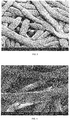
- the pins formed a pattern of indentations in the nonwoven fibers
- increased contact angle samples had a density below 0.12 g/cc, a pattern roughness above 1.5, and a pattern coverage above 20%.
- the contact angle (in degrees) was described by the expression 121.5 + 6.7x(%Pattern Coverage) + 2.0x(Pattern Roughness), with an R2 of 0.9 and a p-value of 0.03.
- Caliper was measured using a micrometer with 50-mm diameter platen and a pressure of 0.05psi. Density was calculated from caliper and nominal basis weight, and bulk inverse of density.
- Surface roughness was defined as the 3D surface area / 2D projected area.
- Surfaces were characterized using Keyence laser confocal microscope, using a 50x or 100x objective lens sufficient to show the embossed patterns in detail. Three or four fiber regions containing patterns were selected and the 3D surface area, 2D projected area, and the ratio of the two were calculated by the VK Analyzer software from Keyence. Values in the table are average values.
- Pattern regions were identified using a “convolve” edge detection method in ImageJ, an open source detection software program developed by NIH (version 1.50b), to identify high contrast areas of the image. "Fiber” regions were identified using an intensity threshold combined with the "pattern” high contrast areas (to make sure all "pattern” pixels were also counted as “fiber” pixels).
Priority Applications (1)
| Application Number | Priority Date | Filing Date | Title |
|---|---|---|---|
| EP18182690.0A EP3594396B1 (fr) | 2018-07-10 | 2018-07-10 | Procédé de production de substrats à base de fibre micro et nano structurés |
Applications Claiming Priority (1)
| Application Number | Priority Date | Filing Date | Title |
|---|---|---|---|
| EP18182690.0A EP3594396B1 (fr) | 2018-07-10 | 2018-07-10 | Procédé de production de substrats à base de fibre micro et nano structurés |
Publications (2)
| Publication Number | Publication Date |
|---|---|
| EP3594396A1 true EP3594396A1 (fr) | 2020-01-15 |
| EP3594396B1 EP3594396B1 (fr) | 2024-01-31 |
Family
ID=63041775
Family Applications (1)
| Application Number | Title | Priority Date | Filing Date |
|---|---|---|---|
| EP18182690.0A Active EP3594396B1 (fr) | 2018-07-10 | 2018-07-10 | Procédé de production de substrats à base de fibre micro et nano structurés |
Country Status (1)
| Country | Link |
|---|---|
| EP (1) | EP3594396B1 (fr) |
Citations (36)
| Publication number | Priority date | Publication date | Assignee | Title |
|---|---|---|---|---|
| US390708A (en) | 1888-10-09 | Corn-planter | ||
| US428267A (en) | 1890-05-20 | Dash-rail for vehicles | ||
| US3338992A (en) | 1959-12-15 | 1967-08-29 | Du Pont | Process for forming non-woven filamentary structures from fiber-forming synthetic organic polymers |
| US3341394A (en) | 1966-12-21 | 1967-09-12 | Du Pont | Sheets of randomly distributed continuous filaments |
| US3494821A (en) | 1967-01-06 | 1970-02-10 | Du Pont | Patterned nonwoven fabric of hydraulically entangled textile fibers and reinforcing fibers |
| US3502763A (en) | 1962-02-03 | 1970-03-24 | Freudenberg Carl Kg | Process of producing non-woven fabric fleece |
| US3542615A (en) | 1967-06-16 | 1970-11-24 | Monsanto Co | Process for producing a nylon non-woven fabric |
| US3692618A (en) | 1969-10-08 | 1972-09-19 | Metallgesellschaft Ag | Continuous filament nonwoven web |
| US3802817A (en) | 1969-10-01 | 1974-04-09 | Asahi Chemical Ind | Apparatus for producing non-woven fleeces |
| US3855046A (en) | 1970-02-27 | 1974-12-17 | Kimberly Clark Co | Pattern bonded continuous filament web |
| US4100324A (en) | 1974-03-26 | 1978-07-11 | Kimberly-Clark Corporation | Nonwoven fabric and method of producing same |
| GB1523727A (en) * | 1974-11-11 | 1978-09-06 | Unitex Ltd | Finishing of knitted fabrics |
| US4144370A (en) | 1975-12-29 | 1979-03-13 | Johnson & Johnson | Textile fabric and method of manufacturing the same |
| US4340563A (en) | 1980-05-05 | 1982-07-20 | Kimberly-Clark Corporation | Method for forming nonwoven webs |
| US4659609A (en) | 1986-05-02 | 1987-04-21 | Kimberly-Clark Corporation | Abrasive web and method of making same |
| US4833003A (en) | 1986-08-15 | 1989-05-23 | Kimberly-Clark Corporation | Uniformly moist abrasive wipes |
| US5108820A (en) | 1989-04-25 | 1992-04-28 | Mitsui Petrochemical Industries, Ltd. | Soft nonwoven fabric of filaments |
| US5284703A (en) | 1990-12-21 | 1994-02-08 | Kimberly-Clark Corporation | High pulp content nonwoven composite fabric |
| US5336552A (en) | 1992-08-26 | 1994-08-09 | Kimberly-Clark Corporation | Nonwoven fabric made with multicomponent polymeric strands including a blend of polyolefin and ethylene alkyl acrylate copolymer |
| US5350624A (en) | 1992-10-05 | 1994-09-27 | Kimberly-Clark Corporation | Abrasion resistant fibrous nonwoven composite structure |
| US5382400A (en) | 1992-08-21 | 1995-01-17 | Kimberly-Clark Corporation | Nonwoven multicomponent polymeric fabric and method for making same |
| US5620779A (en) | 1993-12-23 | 1997-04-15 | Kimberly-Clark Corporation | Ribbed clothlike nonwoven fabric |
| US5759926A (en) | 1995-06-07 | 1998-06-02 | Kimberly-Clark Worldwide, Inc. | Fine denier fibers and fabrics made therefrom |
| US5935883A (en) | 1995-11-30 | 1999-08-10 | Kimberly-Clark Worldwide, Inc. | Superfine microfiber nonwoven web |
| US5962112A (en) | 1996-12-19 | 1999-10-05 | Kimberly-Clark Worldwide, Inc. | Wipers comprising point unbonded webs |
| US6093665A (en) | 1993-09-30 | 2000-07-25 | Kimberly-Clark Worldwide, Inc. | Pattern bonded nonwoven fabrics |
| US6103061A (en) | 1998-07-07 | 2000-08-15 | Kimberly-Clark Worldwide, Inc. | Soft, strong hydraulically entangled nonwoven composite material and method for making the same |
| US6197404B1 (en) | 1997-10-31 | 2001-03-06 | Kimberly-Clark Worldwide, Inc. | Creped nonwoven materials |
| US6200669B1 (en) | 1996-11-26 | 2001-03-13 | Kimberly-Clark Worldwide, Inc. | Entangled nonwoven fabrics and methods for forming the same |
| US6315864B2 (en) | 1997-10-30 | 2001-11-13 | Kimberly-Clark Worldwide, Inc. | Cloth-like base sheet and method for making the same |
| US7632258B2 (en) | 2003-03-19 | 2009-12-15 | Kimberly-Clark Worldwide, Inc. | Multilayer absorbent article |
| US20110221094A1 (en) * | 2010-03-11 | 2011-09-15 | Sarah Beth Gross | Process for making an embossed web |
| US20110287203A1 (en) * | 2010-05-24 | 2011-11-24 | Integran Technologies Inc. | Articles with super-hydrophobic and/or self-cleaning surfaces and method of making same |
| JP2014025305A (ja) * | 2012-07-30 | 2014-02-06 | Nittoc Constr Co Ltd | 繊維 |
| KR20170061550A (ko) * | 2015-11-26 | 2017-06-05 | 한철운 | 원단의 마이크로 엠보 가공 장치 |
| EP3235946A1 (fr) * | 2014-12-15 | 2017-10-25 | Seiren Co., Ltd. | Tissu ayant une conception de surface irrégulière, et son procédé de production |
-
2018
- 2018-07-10 EP EP18182690.0A patent/EP3594396B1/fr active Active
Patent Citations (36)
| Publication number | Priority date | Publication date | Assignee | Title |
|---|---|---|---|---|
| US390708A (en) | 1888-10-09 | Corn-planter | ||
| US428267A (en) | 1890-05-20 | Dash-rail for vehicles | ||
| US3338992A (en) | 1959-12-15 | 1967-08-29 | Du Pont | Process for forming non-woven filamentary structures from fiber-forming synthetic organic polymers |
| US3502763A (en) | 1962-02-03 | 1970-03-24 | Freudenberg Carl Kg | Process of producing non-woven fabric fleece |
| US3341394A (en) | 1966-12-21 | 1967-09-12 | Du Pont | Sheets of randomly distributed continuous filaments |
| US3494821A (en) | 1967-01-06 | 1970-02-10 | Du Pont | Patterned nonwoven fabric of hydraulically entangled textile fibers and reinforcing fibers |
| US3542615A (en) | 1967-06-16 | 1970-11-24 | Monsanto Co | Process for producing a nylon non-woven fabric |
| US3802817A (en) | 1969-10-01 | 1974-04-09 | Asahi Chemical Ind | Apparatus for producing non-woven fleeces |
| US3692618A (en) | 1969-10-08 | 1972-09-19 | Metallgesellschaft Ag | Continuous filament nonwoven web |
| US3855046A (en) | 1970-02-27 | 1974-12-17 | Kimberly Clark Co | Pattern bonded continuous filament web |
| US4100324A (en) | 1974-03-26 | 1978-07-11 | Kimberly-Clark Corporation | Nonwoven fabric and method of producing same |
| GB1523727A (en) * | 1974-11-11 | 1978-09-06 | Unitex Ltd | Finishing of knitted fabrics |
| US4144370A (en) | 1975-12-29 | 1979-03-13 | Johnson & Johnson | Textile fabric and method of manufacturing the same |
| US4340563A (en) | 1980-05-05 | 1982-07-20 | Kimberly-Clark Corporation | Method for forming nonwoven webs |
| US4659609A (en) | 1986-05-02 | 1987-04-21 | Kimberly-Clark Corporation | Abrasive web and method of making same |
| US4833003A (en) | 1986-08-15 | 1989-05-23 | Kimberly-Clark Corporation | Uniformly moist abrasive wipes |
| US5108820A (en) | 1989-04-25 | 1992-04-28 | Mitsui Petrochemical Industries, Ltd. | Soft nonwoven fabric of filaments |
| US5284703A (en) | 1990-12-21 | 1994-02-08 | Kimberly-Clark Corporation | High pulp content nonwoven composite fabric |
| US5382400A (en) | 1992-08-21 | 1995-01-17 | Kimberly-Clark Corporation | Nonwoven multicomponent polymeric fabric and method for making same |
| US5336552A (en) | 1992-08-26 | 1994-08-09 | Kimberly-Clark Corporation | Nonwoven fabric made with multicomponent polymeric strands including a blend of polyolefin and ethylene alkyl acrylate copolymer |
| US5350624A (en) | 1992-10-05 | 1994-09-27 | Kimberly-Clark Corporation | Abrasion resistant fibrous nonwoven composite structure |
| US6093665A (en) | 1993-09-30 | 2000-07-25 | Kimberly-Clark Worldwide, Inc. | Pattern bonded nonwoven fabrics |
| US5620779A (en) | 1993-12-23 | 1997-04-15 | Kimberly-Clark Corporation | Ribbed clothlike nonwoven fabric |
| US5759926A (en) | 1995-06-07 | 1998-06-02 | Kimberly-Clark Worldwide, Inc. | Fine denier fibers and fabrics made therefrom |
| US5935883A (en) | 1995-11-30 | 1999-08-10 | Kimberly-Clark Worldwide, Inc. | Superfine microfiber nonwoven web |
| US6200669B1 (en) | 1996-11-26 | 2001-03-13 | Kimberly-Clark Worldwide, Inc. | Entangled nonwoven fabrics and methods for forming the same |
| US5962112A (en) | 1996-12-19 | 1999-10-05 | Kimberly-Clark Worldwide, Inc. | Wipers comprising point unbonded webs |
| US6315864B2 (en) | 1997-10-30 | 2001-11-13 | Kimberly-Clark Worldwide, Inc. | Cloth-like base sheet and method for making the same |
| US6197404B1 (en) | 1997-10-31 | 2001-03-06 | Kimberly-Clark Worldwide, Inc. | Creped nonwoven materials |
| US6103061A (en) | 1998-07-07 | 2000-08-15 | Kimberly-Clark Worldwide, Inc. | Soft, strong hydraulically entangled nonwoven composite material and method for making the same |
| US7632258B2 (en) | 2003-03-19 | 2009-12-15 | Kimberly-Clark Worldwide, Inc. | Multilayer absorbent article |
| US20110221094A1 (en) * | 2010-03-11 | 2011-09-15 | Sarah Beth Gross | Process for making an embossed web |
| US20110287203A1 (en) * | 2010-05-24 | 2011-11-24 | Integran Technologies Inc. | Articles with super-hydrophobic and/or self-cleaning surfaces and method of making same |
| JP2014025305A (ja) * | 2012-07-30 | 2014-02-06 | Nittoc Constr Co Ltd | 繊維 |
| EP3235946A1 (fr) * | 2014-12-15 | 2017-10-25 | Seiren Co., Ltd. | Tissu ayant une conception de surface irrégulière, et son procédé de production |
| KR20170061550A (ko) * | 2015-11-26 | 2017-06-05 | 한철운 | 원단의 마이크로 엠보 가공 장치 |
Also Published As
| Publication number | Publication date |
|---|---|
| EP3594396B1 (fr) | 2024-01-31 |
Similar Documents
| Publication | Publication Date | Title |
|---|---|---|
| US10258516B2 (en) | Treated three-dimensional apertured liners | |
| AU2014342318B2 (en) | One-way valve nonwoven material | |
| US10442104B2 (en) | Method for making an apertured web | |
| US20040122396A1 (en) | Apertured, film-coated nonwoven material | |
| EP2270271A1 (fr) | Barrière haute non tissée | |
| JP2000504974A (ja) | 改良されたマスキング特性を示す吸収体用の改良されたトップシート | |
| KR20160037222A (ko) | 처리된 3차원 천공 서지 | |
| JP5926687B2 (ja) | 表面処理された不織布 | |
| JP2006183168A (ja) | 繊維シート | |
| JP6408320B2 (ja) | 親水性不織布及び不織布用繊維処理剤 | |
| KR102591959B1 (ko) | 마이크로- 및 나노-구조화된 섬유-기반 기재 | |
| JP2005139594A (ja) | 不織布およびその製造方法 | |
| EP3594396B1 (fr) | Procédé de production de substrats à base de fibre micro et nano structurés | |
| RU2747809C2 (ru) | Способ структурирования смачивания и модели для безнасосного переноса и точного управления объемами жидкостей на пористых материалах и через них | |
| US7144831B2 (en) | Three-dimensional nonwoven substrate having sub-millimeter orifice structure | |
| WO2015166435A1 (fr) | Traitement hydrophobe sur non-tissé hydrophile | |
| EP3177248A1 (fr) | Bande ouverte | |
| CN112313073A (zh) | 具有3d压花的纤维素非织造层合物 | |
| KR102297773B1 (ko) | 발수성 및 공기 투과성이 향상된 일회용 흡수용품 | |
| JP7433583B2 (ja) | 吸収性物品用不織布、吸収性物品用トップシート、およびそれを含む吸収性物品 | |
| Dhiman et al. | Development of a novel fluorocarbon coated acquisition-barrier fabric layer for incontinence application | |
| KR102341363B1 (ko) | 흡수 성능이 개선된 일회용 흡수용품 | |
| KR20160098309A (ko) | 향상된 연성을 갖는 중합체 웹 |
Legal Events
| Date | Code | Title | Description |
|---|---|---|---|
| PUAI | Public reference made under article 153(3) epc to a published international application that has entered the european phase |
Free format text: ORIGINAL CODE: 0009012 |
|
| STAA | Information on the status of an ep patent application or granted ep patent |
Free format text: STATUS: THE APPLICATION HAS BEEN PUBLISHED |
|
| AK | Designated contracting states |
Kind code of ref document: A1 Designated state(s): AL AT BE BG CH CY CZ DE DK EE ES FI FR GB GR HR HU IE IS IT LI LT LU LV MC MK MT NL NO PL PT RO RS SE SI SK SM TR |
|
| AX | Request for extension of the european patent |
Extension state: BA ME |
|
| STAA | Information on the status of an ep patent application or granted ep patent |
Free format text: STATUS: REQUEST FOR EXAMINATION WAS MADE |
|
| 17P | Request for examination filed |
Effective date: 20200625 |
|
| RBV | Designated contracting states (corrected) |
Designated state(s): AL AT BE BG CH CY CZ DE DK EE ES FI FR GB GR HR HU IE IS IT LI LT LU LV MC MK MT NL NO PL PT RO RS SE SI SK SM TR |
|
| STAA | Information on the status of an ep patent application or granted ep patent |
Free format text: STATUS: EXAMINATION IS IN PROGRESS |
|
| STAA | Information on the status of an ep patent application or granted ep patent |
Free format text: STATUS: EXAMINATION IS IN PROGRESS |
|
| 17Q | First examination report despatched |
Effective date: 20210830 |
|
| GRAP | Despatch of communication of intention to grant a patent |
Free format text: ORIGINAL CODE: EPIDOSNIGR1 |
|
| STAA | Information on the status of an ep patent application or granted ep patent |
Free format text: STATUS: GRANT OF PATENT IS INTENDED |
|
| INTG | Intention to grant announced |
Effective date: 20230830 |
|
| GRAS | Grant fee paid |
Free format text: ORIGINAL CODE: EPIDOSNIGR3 |
|
| GRAA | (expected) grant |
Free format text: ORIGINAL CODE: 0009210 |
|
| STAA | Information on the status of an ep patent application or granted ep patent |
Free format text: STATUS: THE PATENT HAS BEEN GRANTED |
|
| AK | Designated contracting states |
Kind code of ref document: B1 Designated state(s): AL AT BE BG CH CY CZ DE DK EE ES FI FR GB GR HR HU IE IS IT LI LT LU LV MC MK MT NL NO PL PT RO RS SE SI SK SM TR |
|
| REG | Reference to a national code |
Ref country code: GB Ref legal event code: FG4D Ref country code: CH Ref legal event code: EP |
|
| REG | Reference to a national code |
Ref country code: DE Ref legal event code: R081 Ref document number: 602018064725 Country of ref document: DE Owner name: KARLSRUHER INSTITUT FUER TECHNOLOGIE, KOERPERS, DE Free format text: FORMER OWNER: ANMELDERANGABEN UNKLAR / UNVOLLSTAENDIG, 80297 MUENCHEN, DE |
|
| REG | Reference to a national code |
Ref country code: DE Ref legal event code: R096 Ref document number: 602018064725 Country of ref document: DE |
|
| REG | Reference to a national code |
Ref country code: IE Ref legal event code: FG4D |