EP3594313A1 - Thermal-chemical utilization of carbon-containing materials, in particular for the emission-free generation of energy - Google Patents
Thermal-chemical utilization of carbon-containing materials, in particular for the emission-free generation of energy Download PDFInfo
- Publication number
- EP3594313A1 EP3594313A1 EP19190005.9A EP19190005A EP3594313A1 EP 3594313 A1 EP3594313 A1 EP 3594313A1 EP 19190005 A EP19190005 A EP 19190005A EP 3594313 A1 EP3594313 A1 EP 3594313A1
- Authority
- EP
- European Patent Office
- Prior art keywords
- process stage
- energy
- gas
- pyrolysis
- pressure
- Prior art date
- Legal status (The legal status is an assumption and is not a legal conclusion. Google has not performed a legal analysis and makes no representation as to the accuracy of the status listed.)
- Pending
Links
- 239000000463 material Substances 0.000 title claims abstract description 91
- OKTJSMMVPCPJKN-UHFFFAOYSA-N Carbon Chemical compound [C] OKTJSMMVPCPJKN-UHFFFAOYSA-N 0.000 title claims abstract description 71
- 229910052799 carbon Inorganic materials 0.000 title claims abstract description 68
- 239000000126 substance Substances 0.000 title description 42
- 238000000034 method Methods 0.000 claims abstract description 304
- 230000008569 process Effects 0.000 claims abstract description 252
- 230000015572 biosynthetic process Effects 0.000 claims abstract description 124
- 238000003786 synthesis reaction Methods 0.000 claims abstract description 120
- CURLTUGMZLYLDI-UHFFFAOYSA-N Carbon dioxide Chemical compound O=C=O CURLTUGMZLYLDI-UHFFFAOYSA-N 0.000 claims abstract description 116
- 238000004064 recycling Methods 0.000 claims abstract description 114
- 238000000197 pyrolysis Methods 0.000 claims abstract description 101
- OKKJLVBELUTLKV-UHFFFAOYSA-N Methanol Chemical compound OC OKKJLVBELUTLKV-UHFFFAOYSA-N 0.000 claims abstract description 72
- 239000001569 carbon dioxide Substances 0.000 claims abstract description 57
- 229910002092 carbon dioxide Inorganic materials 0.000 claims abstract description 57
- 239000000571 coke Substances 0.000 claims abstract description 52
- 150000002430 hydrocarbons Chemical class 0.000 claims abstract description 45
- 229930195733 hydrocarbon Natural products 0.000 claims abstract description 42
- 239000002893 slag Substances 0.000 claims abstract description 12
- 239000007791 liquid phase Substances 0.000 claims abstract description 11
- 239000012298 atmosphere Substances 0.000 claims abstract description 7
- 239000007789 gas Substances 0.000 claims description 274
- XLYOFNOQVPJJNP-UHFFFAOYSA-N water Chemical compound O XLYOFNOQVPJJNP-UHFFFAOYSA-N 0.000 claims description 84
- 238000002485 combustion reaction Methods 0.000 claims description 68
- 229910001868 water Inorganic materials 0.000 claims description 61
- 239000000446 fuel Substances 0.000 claims description 50
- 239000001301 oxygen Substances 0.000 claims description 40
- 229910052760 oxygen Inorganic materials 0.000 claims description 40
- 238000004519 manufacturing process Methods 0.000 claims description 39
- 239000007788 liquid Substances 0.000 claims description 38
- UFHFLCQGNIYNRP-UHFFFAOYSA-N Hydrogen Chemical compound [H][H] UFHFLCQGNIYNRP-UHFFFAOYSA-N 0.000 claims description 37
- 238000006243 chemical reaction Methods 0.000 claims description 35
- 239000007858 starting material Substances 0.000 claims description 33
- 239000001257 hydrogen Substances 0.000 claims description 32
- 229910052739 hydrogen Inorganic materials 0.000 claims description 32
- 238000007254 oxidation reaction Methods 0.000 claims description 32
- 230000001590 oxidative effect Effects 0.000 claims description 31
- 230000003647 oxidation Effects 0.000 claims description 26
- 238000002309 gasification Methods 0.000 claims description 13
- 238000012545 processing Methods 0.000 claims description 13
- 238000011084 recovery Methods 0.000 claims description 12
- 239000003575 carbonaceous material Substances 0.000 claims description 10
- 239000004215 Carbon black (E152) Substances 0.000 claims description 9
- 239000003795 chemical substances by application Substances 0.000 claims description 8
- 150000002431 hydrogen Chemical class 0.000 claims description 7
- VUZPPFZMUPKLLV-UHFFFAOYSA-N methane;hydrate Chemical compound C.O VUZPPFZMUPKLLV-UHFFFAOYSA-N 0.000 claims description 6
- 238000009423 ventilation Methods 0.000 claims description 3
- QVGXLLKOCUKJST-UHFFFAOYSA-N atomic oxygen Chemical compound [O] QVGXLLKOCUKJST-UHFFFAOYSA-N 0.000 claims 5
- 229960004424 carbon dioxide Drugs 0.000 description 50
- MYMOFIZGZYHOMD-UHFFFAOYSA-N Dioxygen Chemical compound O=O MYMOFIZGZYHOMD-UHFFFAOYSA-N 0.000 description 45
- 239000000047 product Substances 0.000 description 44
- 239000007787 solid Substances 0.000 description 29
- 239000000203 mixture Substances 0.000 description 24
- 239000002028 Biomass Substances 0.000 description 23
- UGFAIRIUMAVXCW-UHFFFAOYSA-N Carbon monoxide Chemical compound [O+]#[C-] UGFAIRIUMAVXCW-UHFFFAOYSA-N 0.000 description 18
- 229910002091 carbon monoxide Inorganic materials 0.000 description 17
- 238000001816 cooling Methods 0.000 description 17
- 230000008901 benefit Effects 0.000 description 16
- VNWKTOKETHGBQD-UHFFFAOYSA-N methane Chemical compound C VNWKTOKETHGBQD-UHFFFAOYSA-N 0.000 description 14
- 239000003054 catalyst Substances 0.000 description 13
- IJGRMHOSHXDMSA-UHFFFAOYSA-N nitrogen Substances N#N IJGRMHOSHXDMSA-UHFFFAOYSA-N 0.000 description 11
- 238000003860 storage Methods 0.000 description 11
- 239000000567 combustion gas Substances 0.000 description 10
- 238000010438 heat treatment Methods 0.000 description 10
- 239000003245 coal Substances 0.000 description 9
- 239000012530 fluid Substances 0.000 description 9
- MWUXSHHQAYIFBG-UHFFFAOYSA-N nitrogen oxide Inorganic materials O=[N] MWUXSHHQAYIFBG-UHFFFAOYSA-N 0.000 description 9
- 239000002699 waste material Substances 0.000 description 9
- 238000013461 design Methods 0.000 description 8
- 239000000654 additive Substances 0.000 description 7
- 239000000428 dust Substances 0.000 description 7
- 238000005868 electrolysis reaction Methods 0.000 description 7
- 239000002994 raw material Substances 0.000 description 7
- 239000002956 ash Substances 0.000 description 6
- 239000000872 buffer Substances 0.000 description 6
- 239000006227 byproduct Substances 0.000 description 6
- 229910052757 nitrogen Inorganic materials 0.000 description 6
- 239000007800 oxidant agent Substances 0.000 description 6
- 239000007795 chemical reaction product Substances 0.000 description 5
- 238000009833 condensation Methods 0.000 description 5
- 230000005494 condensation Effects 0.000 description 5
- 239000012071 phase Substances 0.000 description 5
- 230000006835 compression Effects 0.000 description 4
- 238000007906 compression Methods 0.000 description 4
- 239000003344 environmental pollutant Substances 0.000 description 4
- 239000003345 natural gas Substances 0.000 description 4
- 239000003921 oil Substances 0.000 description 4
- 231100000719 pollutant Toxicity 0.000 description 4
- 238000002360 preparation method Methods 0.000 description 4
- 230000009467 reduction Effects 0.000 description 4
- UHOVQNZJYSORNB-UHFFFAOYSA-N Benzene Chemical compound C1=CC=CC=C1 UHOVQNZJYSORNB-UHFFFAOYSA-N 0.000 description 3
- NINIDFKCEFEMDL-UHFFFAOYSA-N Sulfur Chemical compound [S] NINIDFKCEFEMDL-UHFFFAOYSA-N 0.000 description 3
- 125000004122 cyclic group Chemical group 0.000 description 3
- 238000012432 intermediate storage Methods 0.000 description 3
- 238000005065 mining Methods 0.000 description 3
- 239000002245 particle Substances 0.000 description 3
- 238000005192 partition Methods 0.000 description 3
- 239000003208 petroleum Substances 0.000 description 3
- 238000000926 separation method Methods 0.000 description 3
- 229910052717 sulfur Inorganic materials 0.000 description 3
- 239000011593 sulfur Substances 0.000 description 3
- 239000002023 wood Substances 0.000 description 3
- OQCFWECOQNPQCG-UHFFFAOYSA-N 1,3,4,8-tetrahydropyrimido[4,5-c]oxazin-7-one Chemical compound C1CONC2=C1C=NC(=O)N2 OQCFWECOQNPQCG-UHFFFAOYSA-N 0.000 description 2
- XEEYBQQBJWHFJM-UHFFFAOYSA-N Iron Chemical compound [Fe] XEEYBQQBJWHFJM-UHFFFAOYSA-N 0.000 description 2
- PXHVJJICTQNCMI-UHFFFAOYSA-N Nickel Chemical compound [Ni] PXHVJJICTQNCMI-UHFFFAOYSA-N 0.000 description 2
- ATUOYWHBWRKTHZ-UHFFFAOYSA-N Propane Chemical compound CCC ATUOYWHBWRKTHZ-UHFFFAOYSA-N 0.000 description 2
- 230000000996 additive effect Effects 0.000 description 2
- 150000001335 aliphatic alkanes Chemical class 0.000 description 2
- 150000001336 alkenes Chemical class 0.000 description 2
- 230000033228 biological regulation Effects 0.000 description 2
- 230000005540 biological transmission Effects 0.000 description 2
- 238000012993 chemical processing Methods 0.000 description 2
- 238000004140 cleaning Methods 0.000 description 2
- 238000010276 construction Methods 0.000 description 2
- 230000001419 dependent effect Effects 0.000 description 2
- 230000000694 effects Effects 0.000 description 2
- 238000004146 energy storage Methods 0.000 description 2
- 239000002803 fossil fuel Substances 0.000 description 2
- 239000000295 fuel oil Substances 0.000 description 2
- 239000003502 gasoline Substances 0.000 description 2
- 239000010439 graphite Substances 0.000 description 2
- 229910002804 graphite Inorganic materials 0.000 description 2
- 239000002638 heterogeneous catalyst Substances 0.000 description 2
- 239000011261 inert gas Substances 0.000 description 2
- 238000002347 injection Methods 0.000 description 2
- 239000007924 injection Substances 0.000 description 2
- 239000012263 liquid product Substances 0.000 description 2
- 238000011068 loading method Methods 0.000 description 2
- 238000002844 melting Methods 0.000 description 2
- 230000008018 melting Effects 0.000 description 2
- 229910052751 metal Inorganic materials 0.000 description 2
- 239000002184 metal Substances 0.000 description 2
- 239000002480 mineral oil Substances 0.000 description 2
- 235000010446 mineral oil Nutrition 0.000 description 2
- 239000004058 oil shale Substances 0.000 description 2
- 230000001172 regenerating effect Effects 0.000 description 2
- 239000010802 sludge Substances 0.000 description 2
- 239000002002 slurry Substances 0.000 description 2
- 239000000725 suspension Substances 0.000 description 2
- 238000011144 upstream manufacturing Methods 0.000 description 2
- 238000013022 venting Methods 0.000 description 2
- 238000010792 warming Methods 0.000 description 2
- 239000001993 wax Substances 0.000 description 2
- KVGZZAHHUNAVKZ-UHFFFAOYSA-N 1,4-Dioxin Chemical compound O1C=COC=C1 KVGZZAHHUNAVKZ-UHFFFAOYSA-N 0.000 description 1
- 235000008733 Citrus aurantifolia Nutrition 0.000 description 1
- 235000002918 Fraxinus excelsior Nutrition 0.000 description 1
- OAICVXFJPJFONN-UHFFFAOYSA-N Phosphorus Chemical compound [P] OAICVXFJPJFONN-UHFFFAOYSA-N 0.000 description 1
- KJTLSVCANCCWHF-UHFFFAOYSA-N Ruthenium Chemical compound [Ru] KJTLSVCANCCWHF-UHFFFAOYSA-N 0.000 description 1
- 235000011941 Tilia x europaea Nutrition 0.000 description 1
- 150000001298 alcohols Chemical class 0.000 description 1
- 150000001299 aldehydes Chemical class 0.000 description 1
- 150000001412 amines Chemical class 0.000 description 1
- 238000013459 approach Methods 0.000 description 1
- 238000004577 artificial photosynthesis Methods 0.000 description 1
- 239000002551 biofuel Substances 0.000 description 1
- 238000009835 boiling Methods 0.000 description 1
- 239000003990 capacitor Substances 0.000 description 1
- 150000001722 carbon compounds Chemical class 0.000 description 1
- UBAZGMLMVVQSCD-UHFFFAOYSA-N carbon dioxide;molecular oxygen Chemical compound O=O.O=C=O UBAZGMLMVVQSCD-UHFFFAOYSA-N 0.000 description 1
- 239000000969 carrier Substances 0.000 description 1
- 238000004517 catalytic hydrocracking Methods 0.000 description 1
- 239000000919 ceramic Substances 0.000 description 1
- 230000008859 change Effects 0.000 description 1
- 229910017052 cobalt Inorganic materials 0.000 description 1
- 239000010941 cobalt Substances 0.000 description 1
- GUTLYIVDDKVIGB-UHFFFAOYSA-N cobalt atom Chemical compound [Co] GUTLYIVDDKVIGB-UHFFFAOYSA-N 0.000 description 1
- 239000010849 combustible waste Substances 0.000 description 1
- 150000001875 compounds Chemical class 0.000 description 1
- 230000007797 corrosion Effects 0.000 description 1
- 238000005260 corrosion Methods 0.000 description 1
- 238000005336 cracking Methods 0.000 description 1
- 230000007423 decrease Effects 0.000 description 1
- 230000003247 decreasing effect Effects 0.000 description 1
- 230000008021 deposition Effects 0.000 description 1
- 239000002283 diesel fuel Substances 0.000 description 1
- 150000002013 dioxins Chemical class 0.000 description 1
- 229910001882 dioxygen Inorganic materials 0.000 description 1
- 238000007599 discharging Methods 0.000 description 1
- 230000005611 electricity Effects 0.000 description 1
- 238000005265 energy consumption Methods 0.000 description 1
- 230000007613 environmental effect Effects 0.000 description 1
- 230000007717 exclusion Effects 0.000 description 1
- 239000002360 explosive Substances 0.000 description 1
- 230000002349 favourable effect Effects 0.000 description 1
- 239000003546 flue gas Substances 0.000 description 1
- 239000002737 fuel gas Substances 0.000 description 1
- 239000011521 glass Substances 0.000 description 1
- 239000008236 heating water Substances 0.000 description 1
- 239000008241 heterogeneous mixture Substances 0.000 description 1
- 239000012535 impurity Substances 0.000 description 1
- 230000003993 interaction Effects 0.000 description 1
- 230000002452 interceptive effect Effects 0.000 description 1
- 229910052742 iron Inorganic materials 0.000 description 1
- 239000004571 lime Substances 0.000 description 1
- 239000011344 liquid material Substances 0.000 description 1
- 230000007774 longterm Effects 0.000 description 1
- 230000014759 maintenance of location Effects 0.000 description 1
- 150000002739 metals Chemical class 0.000 description 1
- 238000002156 mixing Methods 0.000 description 1
- 238000012986 modification Methods 0.000 description 1
- 230000004048 modification Effects 0.000 description 1
- 229910052759 nickel Inorganic materials 0.000 description 1
- 239000010742 number 1 fuel oil Substances 0.000 description 1
- 239000003027 oil sand Substances 0.000 description 1
- 238000005457 optimization Methods 0.000 description 1
- 150000007524 organic acids Chemical class 0.000 description 1
- 235000005985 organic acids Nutrition 0.000 description 1
- 239000011368 organic material Substances 0.000 description 1
- 150000002927 oxygen compounds Chemical class 0.000 description 1
- 239000003209 petroleum derivative Substances 0.000 description 1
- 229910052698 phosphorus Inorganic materials 0.000 description 1
- 239000011574 phosphorus Substances 0.000 description 1
- 239000002574 poison Substances 0.000 description 1
- 231100000614 poison Toxicity 0.000 description 1
- 231100000572 poisoning Toxicity 0.000 description 1
- 230000000607 poisoning effect Effects 0.000 description 1
- 239000000843 powder Substances 0.000 description 1
- 238000010248 power generation Methods 0.000 description 1
- 239000001294 propane Substances 0.000 description 1
- 238000000746 purification Methods 0.000 description 1
- 239000011541 reaction mixture Substances 0.000 description 1
- 230000002040 relaxant effect Effects 0.000 description 1
- 238000011160 research Methods 0.000 description 1
- 229910052707 ruthenium Inorganic materials 0.000 description 1
- 239000002689 soil Substances 0.000 description 1
- 239000011949 solid catalyst Substances 0.000 description 1
- 239000011343 solid material Substances 0.000 description 1
- 239000002904 solvent Substances 0.000 description 1
- 238000001228 spectrum Methods 0.000 description 1
- 239000010902 straw Substances 0.000 description 1
- 150000003464 sulfur compounds Chemical class 0.000 description 1
- 238000009997 thermal pre-treatment Methods 0.000 description 1
- 230000007306 turnover Effects 0.000 description 1
- 239000011345 viscous material Substances 0.000 description 1
- 239000002918 waste heat Substances 0.000 description 1
Images


Classifications
-
- C—CHEMISTRY; METALLURGY
- C10—PETROLEUM, GAS OR COKE INDUSTRIES; TECHNICAL GASES CONTAINING CARBON MONOXIDE; FUELS; LUBRICANTS; PEAT
- C10J—PRODUCTION OF PRODUCER GAS, WATER-GAS, SYNTHESIS GAS FROM SOLID CARBONACEOUS MATERIAL, OR MIXTURES CONTAINING THESE GASES; CARBURETTING AIR OR OTHER GASES
- C10J3/00—Production of combustible gases containing carbon monoxide from solid carbonaceous fuels
- C10J3/58—Production of combustible gases containing carbon monoxide from solid carbonaceous fuels combined with pre-distillation of the fuel
- C10J3/60—Processes
- C10J3/64—Processes with decomposition of the distillation products
- C10J3/66—Processes with decomposition of the distillation products by introducing them into the gasification zone
-
- C—CHEMISTRY; METALLURGY
- C07—ORGANIC CHEMISTRY
- C07C—ACYCLIC OR CARBOCYCLIC COMPOUNDS
- C07C29/00—Preparation of compounds having hydroxy or O-metal groups bound to a carbon atom not belonging to a six-membered aromatic ring
- C07C29/15—Preparation of compounds having hydroxy or O-metal groups bound to a carbon atom not belonging to a six-membered aromatic ring by reduction of oxides of carbon exclusively
- C07C29/151—Preparation of compounds having hydroxy or O-metal groups bound to a carbon atom not belonging to a six-membered aromatic ring by reduction of oxides of carbon exclusively with hydrogen or hydrogen-containing gases
-
- C—CHEMISTRY; METALLURGY
- C10—PETROLEUM, GAS OR COKE INDUSTRIES; TECHNICAL GASES CONTAINING CARBON MONOXIDE; FUELS; LUBRICANTS; PEAT
- C10G—CRACKING HYDROCARBON OILS; PRODUCTION OF LIQUID HYDROCARBON MIXTURES, e.g. BY DESTRUCTIVE HYDROGENATION, OLIGOMERISATION, POLYMERISATION; RECOVERY OF HYDROCARBON OILS FROM OIL-SHALE, OIL-SAND, OR GASES; REFINING MIXTURES MAINLY CONSISTING OF HYDROCARBONS; REFORMING OF NAPHTHA; MINERAL WAXES
- C10G2/00—Production of liquid hydrocarbon mixtures of undefined composition from oxides of carbon
- C10G2/30—Production of liquid hydrocarbon mixtures of undefined composition from oxides of carbon from carbon monoxide with hydrogen
-
- C—CHEMISTRY; METALLURGY
- C10—PETROLEUM, GAS OR COKE INDUSTRIES; TECHNICAL GASES CONTAINING CARBON MONOXIDE; FUELS; LUBRICANTS; PEAT
- C10J—PRODUCTION OF PRODUCER GAS, WATER-GAS, SYNTHESIS GAS FROM SOLID CARBONACEOUS MATERIAL, OR MIXTURES CONTAINING THESE GASES; CARBURETTING AIR OR OTHER GASES
- C10J3/00—Production of combustible gases containing carbon monoxide from solid carbonaceous fuels
- C10J3/02—Fixed-bed gasification of lump fuel
- C10J3/20—Apparatus; Plants
- C10J3/34—Grates; Mechanical ash-removing devices
- C10J3/40—Movable grates
-
- C—CHEMISTRY; METALLURGY
- C10—PETROLEUM, GAS OR COKE INDUSTRIES; TECHNICAL GASES CONTAINING CARBON MONOXIDE; FUELS; LUBRICANTS; PEAT
- C10J—PRODUCTION OF PRODUCER GAS, WATER-GAS, SYNTHESIS GAS FROM SOLID CARBONACEOUS MATERIAL, OR MIXTURES CONTAINING THESE GASES; CARBURETTING AIR OR OTHER GASES
- C10J3/00—Production of combustible gases containing carbon monoxide from solid carbonaceous fuels
- C10J3/58—Production of combustible gases containing carbon monoxide from solid carbonaceous fuels combined with pre-distillation of the fuel
-
- F—MECHANICAL ENGINEERING; LIGHTING; HEATING; WEAPONS; BLASTING
- F01—MACHINES OR ENGINES IN GENERAL; ENGINE PLANTS IN GENERAL; STEAM ENGINES
- F01K—STEAM ENGINE PLANTS; STEAM ACCUMULATORS; ENGINE PLANTS NOT OTHERWISE PROVIDED FOR; ENGINES USING SPECIAL WORKING FLUIDS OR CYCLES
- F01K13/00—General layout or general methods of operation of complete plants
-
- F—MECHANICAL ENGINEERING; LIGHTING; HEATING; WEAPONS; BLASTING
- F01—MACHINES OR ENGINES IN GENERAL; ENGINE PLANTS IN GENERAL; STEAM ENGINES
- F01K—STEAM ENGINE PLANTS; STEAM ACCUMULATORS; ENGINE PLANTS NOT OTHERWISE PROVIDED FOR; ENGINES USING SPECIAL WORKING FLUIDS OR CYCLES
- F01K23/00—Plants characterised by more than one engine delivering power external to the plant, the engines being driven by different fluids
- F01K23/02—Plants characterised by more than one engine delivering power external to the plant, the engines being driven by different fluids the engine cycles being thermally coupled
- F01K23/06—Plants characterised by more than one engine delivering power external to the plant, the engines being driven by different fluids the engine cycles being thermally coupled combustion heat from one cycle heating the fluid in another cycle
-
- F—MECHANICAL ENGINEERING; LIGHTING; HEATING; WEAPONS; BLASTING
- F02—COMBUSTION ENGINES; HOT-GAS OR COMBUSTION-PRODUCT ENGINE PLANTS
- F02C—GAS-TURBINE PLANTS; AIR INTAKES FOR JET-PROPULSION PLANTS; CONTROLLING FUEL SUPPLY IN AIR-BREATHING JET-PROPULSION PLANTS
- F02C3/00—Gas-turbine plants characterised by the use of combustion products as the working fluid
- F02C3/20—Gas-turbine plants characterised by the use of combustion products as the working fluid using a special fuel, oxidant, or dilution fluid to generate the combustion products
- F02C3/26—Gas-turbine plants characterised by the use of combustion products as the working fluid using a special fuel, oxidant, or dilution fluid to generate the combustion products the fuel or oxidant being solid or pulverulent, e.g. in slurry or suspension
- F02C3/28—Gas-turbine plants characterised by the use of combustion products as the working fluid using a special fuel, oxidant, or dilution fluid to generate the combustion products the fuel or oxidant being solid or pulverulent, e.g. in slurry or suspension using a separate gas producer for gasifying the fuel before combustion
-
- C—CHEMISTRY; METALLURGY
- C10—PETROLEUM, GAS OR COKE INDUSTRIES; TECHNICAL GASES CONTAINING CARBON MONOXIDE; FUELS; LUBRICANTS; PEAT
- C10G—CRACKING HYDROCARBON OILS; PRODUCTION OF LIQUID HYDROCARBON MIXTURES, e.g. BY DESTRUCTIVE HYDROGENATION, OLIGOMERISATION, POLYMERISATION; RECOVERY OF HYDROCARBON OILS FROM OIL-SHALE, OIL-SAND, OR GASES; REFINING MIXTURES MAINLY CONSISTING OF HYDROCARBONS; REFORMING OF NAPHTHA; MINERAL WAXES
- C10G2300/00—Aspects relating to hydrocarbon processing covered by groups C10G1/00 - C10G99/00
- C10G2300/10—Feedstock materials
- C10G2300/1011—Biomass
-
- C—CHEMISTRY; METALLURGY
- C10—PETROLEUM, GAS OR COKE INDUSTRIES; TECHNICAL GASES CONTAINING CARBON MONOXIDE; FUELS; LUBRICANTS; PEAT
- C10G—CRACKING HYDROCARBON OILS; PRODUCTION OF LIQUID HYDROCARBON MIXTURES, e.g. BY DESTRUCTIVE HYDROGENATION, OLIGOMERISATION, POLYMERISATION; RECOVERY OF HYDROCARBON OILS FROM OIL-SHALE, OIL-SAND, OR GASES; REFINING MIXTURES MAINLY CONSISTING OF HYDROCARBONS; REFORMING OF NAPHTHA; MINERAL WAXES
- C10G2300/00—Aspects relating to hydrocarbon processing covered by groups C10G1/00 - C10G99/00
- C10G2300/10—Feedstock materials
- C10G2300/1022—Fischer-Tropsch products
-
- C—CHEMISTRY; METALLURGY
- C10—PETROLEUM, GAS OR COKE INDUSTRIES; TECHNICAL GASES CONTAINING CARBON MONOXIDE; FUELS; LUBRICANTS; PEAT
- C10G—CRACKING HYDROCARBON OILS; PRODUCTION OF LIQUID HYDROCARBON MIXTURES, e.g. BY DESTRUCTIVE HYDROGENATION, OLIGOMERISATION, POLYMERISATION; RECOVERY OF HYDROCARBON OILS FROM OIL-SHALE, OIL-SAND, OR GASES; REFINING MIXTURES MAINLY CONSISTING OF HYDROCARBONS; REFORMING OF NAPHTHA; MINERAL WAXES
- C10G2300/00—Aspects relating to hydrocarbon processing covered by groups C10G1/00 - C10G99/00
- C10G2300/40—Characteristics of the process deviating from typical ways of processing
- C10G2300/4037—In-situ processes
-
- C—CHEMISTRY; METALLURGY
- C10—PETROLEUM, GAS OR COKE INDUSTRIES; TECHNICAL GASES CONTAINING CARBON MONOXIDE; FUELS; LUBRICANTS; PEAT
- C10G—CRACKING HYDROCARBON OILS; PRODUCTION OF LIQUID HYDROCARBON MIXTURES, e.g. BY DESTRUCTIVE HYDROGENATION, OLIGOMERISATION, POLYMERISATION; RECOVERY OF HYDROCARBON OILS FROM OIL-SHALE, OIL-SAND, OR GASES; REFINING MIXTURES MAINLY CONSISTING OF HYDROCARBONS; REFORMING OF NAPHTHA; MINERAL WAXES
- C10G2300/00—Aspects relating to hydrocarbon processing covered by groups C10G1/00 - C10G99/00
- C10G2300/40—Characteristics of the process deviating from typical ways of processing
- C10G2300/4081—Recycling aspects
-
- C—CHEMISTRY; METALLURGY
- C10—PETROLEUM, GAS OR COKE INDUSTRIES; TECHNICAL GASES CONTAINING CARBON MONOXIDE; FUELS; LUBRICANTS; PEAT
- C10J—PRODUCTION OF PRODUCER GAS, WATER-GAS, SYNTHESIS GAS FROM SOLID CARBONACEOUS MATERIAL, OR MIXTURES CONTAINING THESE GASES; CARBURETTING AIR OR OTHER GASES
- C10J2300/00—Details of gasification processes
- C10J2300/09—Details of the feed, e.g. feeding of spent catalyst, inert gas or halogens
- C10J2300/0913—Carbonaceous raw material
- C10J2300/094—Char
-
- C—CHEMISTRY; METALLURGY
- C10—PETROLEUM, GAS OR COKE INDUSTRIES; TECHNICAL GASES CONTAINING CARBON MONOXIDE; FUELS; LUBRICANTS; PEAT
- C10J—PRODUCTION OF PRODUCER GAS, WATER-GAS, SYNTHESIS GAS FROM SOLID CARBONACEOUS MATERIAL, OR MIXTURES CONTAINING THESE GASES; CARBURETTING AIR OR OTHER GASES
- C10J2300/00—Details of gasification processes
- C10J2300/09—Details of the feed, e.g. feeding of spent catalyst, inert gas or halogens
- C10J2300/0953—Gasifying agents
- C10J2300/0959—Oxygen
-
- C—CHEMISTRY; METALLURGY
- C10—PETROLEUM, GAS OR COKE INDUSTRIES; TECHNICAL GASES CONTAINING CARBON MONOXIDE; FUELS; LUBRICANTS; PEAT
- C10J—PRODUCTION OF PRODUCER GAS, WATER-GAS, SYNTHESIS GAS FROM SOLID CARBONACEOUS MATERIAL, OR MIXTURES CONTAINING THESE GASES; CARBURETTING AIR OR OTHER GASES
- C10J2300/00—Details of gasification processes
- C10J2300/09—Details of the feed, e.g. feeding of spent catalyst, inert gas or halogens
- C10J2300/0953—Gasifying agents
- C10J2300/0966—Hydrogen
-
- C—CHEMISTRY; METALLURGY
- C10—PETROLEUM, GAS OR COKE INDUSTRIES; TECHNICAL GASES CONTAINING CARBON MONOXIDE; FUELS; LUBRICANTS; PEAT
- C10J—PRODUCTION OF PRODUCER GAS, WATER-GAS, SYNTHESIS GAS FROM SOLID CARBONACEOUS MATERIAL, OR MIXTURES CONTAINING THESE GASES; CARBURETTING AIR OR OTHER GASES
- C10J2300/00—Details of gasification processes
- C10J2300/09—Details of the feed, e.g. feeding of spent catalyst, inert gas or halogens
- C10J2300/0953—Gasifying agents
- C10J2300/0969—Carbon dioxide
-
- C—CHEMISTRY; METALLURGY
- C10—PETROLEUM, GAS OR COKE INDUSTRIES; TECHNICAL GASES CONTAINING CARBON MONOXIDE; FUELS; LUBRICANTS; PEAT
- C10J—PRODUCTION OF PRODUCER GAS, WATER-GAS, SYNTHESIS GAS FROM SOLID CARBONACEOUS MATERIAL, OR MIXTURES CONTAINING THESE GASES; CARBURETTING AIR OR OTHER GASES
- C10J2300/00—Details of gasification processes
- C10J2300/16—Integration of gasification processes with another plant or parts within the plant
- C10J2300/1603—Integration of gasification processes with another plant or parts within the plant with gas treatment
- C10J2300/1606—Combustion processes
-
- C—CHEMISTRY; METALLURGY
- C10—PETROLEUM, GAS OR COKE INDUSTRIES; TECHNICAL GASES CONTAINING CARBON MONOXIDE; FUELS; LUBRICANTS; PEAT
- C10J—PRODUCTION OF PRODUCER GAS, WATER-GAS, SYNTHESIS GAS FROM SOLID CARBONACEOUS MATERIAL, OR MIXTURES CONTAINING THESE GASES; CARBURETTING AIR OR OTHER GASES
- C10J2300/00—Details of gasification processes
- C10J2300/16—Integration of gasification processes with another plant or parts within the plant
- C10J2300/164—Integration of gasification processes with another plant or parts within the plant with conversion of synthesis gas
- C10J2300/1656—Conversion of synthesis gas to chemicals
- C10J2300/1659—Conversion of synthesis gas to chemicals to liquid hydrocarbons
-
- C—CHEMISTRY; METALLURGY
- C10—PETROLEUM, GAS OR COKE INDUSTRIES; TECHNICAL GASES CONTAINING CARBON MONOXIDE; FUELS; LUBRICANTS; PEAT
- C10J—PRODUCTION OF PRODUCER GAS, WATER-GAS, SYNTHESIS GAS FROM SOLID CARBONACEOUS MATERIAL, OR MIXTURES CONTAINING THESE GASES; CARBURETTING AIR OR OTHER GASES
- C10J2300/00—Details of gasification processes
- C10J2300/16—Integration of gasification processes with another plant or parts within the plant
- C10J2300/164—Integration of gasification processes with another plant or parts within the plant with conversion of synthesis gas
- C10J2300/1656—Conversion of synthesis gas to chemicals
- C10J2300/1665—Conversion of synthesis gas to chemicals to alcohols, e.g. methanol or ethanol
-
- C—CHEMISTRY; METALLURGY
- C10—PETROLEUM, GAS OR COKE INDUSTRIES; TECHNICAL GASES CONTAINING CARBON MONOXIDE; FUELS; LUBRICANTS; PEAT
- C10J—PRODUCTION OF PRODUCER GAS, WATER-GAS, SYNTHESIS GAS FROM SOLID CARBONACEOUS MATERIAL, OR MIXTURES CONTAINING THESE GASES; CARBURETTING AIR OR OTHER GASES
- C10J2300/00—Details of gasification processes
- C10J2300/16—Integration of gasification processes with another plant or parts within the plant
- C10J2300/1671—Integration of gasification processes with another plant or parts within the plant with the production of electricity
- C10J2300/1675—Integration of gasification processes with another plant or parts within the plant with the production of electricity making use of a steam turbine
-
- C—CHEMISTRY; METALLURGY
- C10—PETROLEUM, GAS OR COKE INDUSTRIES; TECHNICAL GASES CONTAINING CARBON MONOXIDE; FUELS; LUBRICANTS; PEAT
- C10J—PRODUCTION OF PRODUCER GAS, WATER-GAS, SYNTHESIS GAS FROM SOLID CARBONACEOUS MATERIAL, OR MIXTURES CONTAINING THESE GASES; CARBURETTING AIR OR OTHER GASES
- C10J2300/00—Details of gasification processes
- C10J2300/16—Integration of gasification processes with another plant or parts within the plant
- C10J2300/1693—Integration of gasification processes with another plant or parts within the plant with storage facilities for intermediate, feed and/or product
-
- C—CHEMISTRY; METALLURGY
- C10—PETROLEUM, GAS OR COKE INDUSTRIES; TECHNICAL GASES CONTAINING CARBON MONOXIDE; FUELS; LUBRICANTS; PEAT
- C10J—PRODUCTION OF PRODUCER GAS, WATER-GAS, SYNTHESIS GAS FROM SOLID CARBONACEOUS MATERIAL, OR MIXTURES CONTAINING THESE GASES; CARBURETTING AIR OR OTHER GASES
- C10J2300/00—Details of gasification processes
- C10J2300/18—Details of the gasification process, e.g. loops, autothermal operation
- C10J2300/1807—Recycle loops, e.g. gas, solids, heating medium, water
- C10J2300/1823—Recycle loops, e.g. gas, solids, heating medium, water for synthesis gas
-
- C—CHEMISTRY; METALLURGY
- C10—PETROLEUM, GAS OR COKE INDUSTRIES; TECHNICAL GASES CONTAINING CARBON MONOXIDE; FUELS; LUBRICANTS; PEAT
- C10J—PRODUCTION OF PRODUCER GAS, WATER-GAS, SYNTHESIS GAS FROM SOLID CARBONACEOUS MATERIAL, OR MIXTURES CONTAINING THESE GASES; CARBURETTING AIR OR OTHER GASES
- C10J2300/00—Details of gasification processes
- C10J2300/18—Details of the gasification process, e.g. loops, autothermal operation
- C10J2300/1846—Partial oxidation, i.e. injection of air or oxygen only
-
- C—CHEMISTRY; METALLURGY
- C10—PETROLEUM, GAS OR COKE INDUSTRIES; TECHNICAL GASES CONTAINING CARBON MONOXIDE; FUELS; LUBRICANTS; PEAT
- C10J—PRODUCTION OF PRODUCER GAS, WATER-GAS, SYNTHESIS GAS FROM SOLID CARBONACEOUS MATERIAL, OR MIXTURES CONTAINING THESE GASES; CARBURETTING AIR OR OTHER GASES
- C10J2300/00—Details of gasification processes
- C10J2300/18—Details of the gasification process, e.g. loops, autothermal operation
- C10J2300/1861—Heat exchange between at least two process streams
- C10J2300/1884—Heat exchange between at least two process streams with one stream being synthesis gas
-
- C—CHEMISTRY; METALLURGY
- C10—PETROLEUM, GAS OR COKE INDUSTRIES; TECHNICAL GASES CONTAINING CARBON MONOXIDE; FUELS; LUBRICANTS; PEAT
- C10J—PRODUCTION OF PRODUCER GAS, WATER-GAS, SYNTHESIS GAS FROM SOLID CARBONACEOUS MATERIAL, OR MIXTURES CONTAINING THESE GASES; CARBURETTING AIR OR OTHER GASES
- C10J2300/00—Details of gasification processes
- C10J2300/18—Details of the gasification process, e.g. loops, autothermal operation
- C10J2300/1861—Heat exchange between at least two process streams
- C10J2300/1892—Heat exchange between at least two process streams with one stream being water/steam
-
- F—MECHANICAL ENGINEERING; LIGHTING; HEATING; WEAPONS; BLASTING
- F23—COMBUSTION APPARATUS; COMBUSTION PROCESSES
- F23C—METHODS OR APPARATUS FOR COMBUSTION USING FLUID FUEL OR SOLID FUEL SUSPENDED IN A CARRIER GAS OR AIR
- F23C2900/00—Special features of, or arrangements for combustion apparatus using fluid fuels or solid fuels suspended in air; Combustion processes therefor
- F23C2900/9901—Combustion process using hydrogen, hydrogen peroxide water or brown gas as fuel
-
- Y—GENERAL TAGGING OF NEW TECHNOLOGICAL DEVELOPMENTS; GENERAL TAGGING OF CROSS-SECTIONAL TECHNOLOGIES SPANNING OVER SEVERAL SECTIONS OF THE IPC; TECHNICAL SUBJECTS COVERED BY FORMER USPC CROSS-REFERENCE ART COLLECTIONS [XRACs] AND DIGESTS
- Y02—TECHNOLOGIES OR APPLICATIONS FOR MITIGATION OR ADAPTATION AGAINST CLIMATE CHANGE
- Y02E—REDUCTION OF GREENHOUSE GAS [GHG] EMISSIONS, RELATED TO ENERGY GENERATION, TRANSMISSION OR DISTRIBUTION
- Y02E20/00—Combustion technologies with mitigation potential
- Y02E20/12—Heat utilisation in combustion or incineration of waste
-
- Y—GENERAL TAGGING OF NEW TECHNOLOGICAL DEVELOPMENTS; GENERAL TAGGING OF CROSS-SECTIONAL TECHNOLOGIES SPANNING OVER SEVERAL SECTIONS OF THE IPC; TECHNICAL SUBJECTS COVERED BY FORMER USPC CROSS-REFERENCE ART COLLECTIONS [XRACs] AND DIGESTS
- Y02—TECHNOLOGIES OR APPLICATIONS FOR MITIGATION OR ADAPTATION AGAINST CLIMATE CHANGE
- Y02E—REDUCTION OF GREENHOUSE GAS [GHG] EMISSIONS, RELATED TO ENERGY GENERATION, TRANSMISSION OR DISTRIBUTION
- Y02E20/00—Combustion technologies with mitigation potential
- Y02E20/32—Direct CO2 mitigation
-
- Y—GENERAL TAGGING OF NEW TECHNOLOGICAL DEVELOPMENTS; GENERAL TAGGING OF CROSS-SECTIONAL TECHNOLOGIES SPANNING OVER SEVERAL SECTIONS OF THE IPC; TECHNICAL SUBJECTS COVERED BY FORMER USPC CROSS-REFERENCE ART COLLECTIONS [XRACs] AND DIGESTS
- Y02—TECHNOLOGIES OR APPLICATIONS FOR MITIGATION OR ADAPTATION AGAINST CLIMATE CHANGE
- Y02E—REDUCTION OF GREENHOUSE GAS [GHG] EMISSIONS, RELATED TO ENERGY GENERATION, TRANSMISSION OR DISTRIBUTION
- Y02E50/00—Technologies for the production of fuel of non-fossil origin
- Y02E50/10—Biofuels, e.g. bio-diesel
-
- Y—GENERAL TAGGING OF NEW TECHNOLOGICAL DEVELOPMENTS; GENERAL TAGGING OF CROSS-SECTIONAL TECHNOLOGIES SPANNING OVER SEVERAL SECTIONS OF THE IPC; TECHNICAL SUBJECTS COVERED BY FORMER USPC CROSS-REFERENCE ART COLLECTIONS [XRACs] AND DIGESTS
- Y02—TECHNOLOGIES OR APPLICATIONS FOR MITIGATION OR ADAPTATION AGAINST CLIMATE CHANGE
- Y02P—CLIMATE CHANGE MITIGATION TECHNOLOGIES IN THE PRODUCTION OR PROCESSING OF GOODS
- Y02P30/00—Technologies relating to oil refining and petrochemical industry
- Y02P30/20—Technologies relating to oil refining and petrochemical industry using bio-feedstock
Definitions
- the invention relates to methods and devices for emission-free energy production by thermal chemical processing and recycling of solid, liquid and gaseous carbonaceous materials and mixtures, in particular waste, biomass, coal, and other heterogeneous materials.
- the invention further relates to devices for generating electrical and mechanical energy and corresponding methods, and also to the production of synthetic hydrocarbons, and their use in such devices.
- carbon dioxide is an inevitable by-product of energy generation. With reasonable energy and / or economic effort, it is generally not possible to separate carbon dioxide from the combustion gases that are produced.
- gas mixtures can be produced from solid, liquid and gaseous carbon-containing materials, which are then used as so-called synthesis gas for chemical syntheses.
- Synthesis gases with carbon monoxide and hydrogen are used, for example, for industrial liquid-phase methanol synthesis or for Fischer-Tropsch synthesis for the production of hydrocarbons and other organic materials.
- synthesis gases are also used to generate energy, for example as a fuel for operating heat engines.
- the thermal energy required for the endothermic reactions I and II to proceed can, for example, come from partial combustion of the solid carbon in reaction III, or be supplied externally.
- the solid carbon for the gasification reactions is in the form of coke. This is in turn generated in a previous process step by pyrolysis of coal or other carbon-containing materials.
- the pyrolysis gases produced during the pyrolysis are burned, the hot carbon dioxide-containing combustion gases serving both as a gasifying agent for the coke and as an external heat energy supplier.
- the coke is gasified with the addition of air / oxygen, the thermal energy being generated primarily by the partial combustion of the carbon of the coke.
- Pyrolysis gas from a previous pyrolysis stage is then mixed into the hot synthesis gas, where it is cracked, so that a tar-free combustible gas mixture is formed.
- a disadvantage of the known methods is the generation of emissions, the low efficiency, and the complicated structure and operation, particularly in plants in which coke is gasified in the eddy current or entrained flow.
- the pyrolysis coke is ground and blown into the gas stream of the second process stage, where the coke dust is gasified endothermically in the entrained flow to synthesis gas.
- a corresponding procedure is described in EP 1749872 A2 disclosed.
- the resulting synthesis gas is used to produce diesel-analog fuel in a multi-stage Fischer-Tropsch synthesis. Resulting exhaust gases including the carbon dioxide generated in the pyrolysis and gasification stage are released into the atmosphere.
- exhaust gases consisting mainly of carbon dioxide and possibly inert gases such as air-nitrogen are released into the atmosphere.
- the object of the invention is to provide methods and devices for emission-free energy generation by thermal-chemical processing and recycling of solid, liquid and gaseous carbonaceous materials and mixtures, in particular waste, biomass, coal and other heterogeneous materials, which the above mentioned and do not have other disadvantages.
- Methods and devices according to the invention should in particular be as emission-free as possible.
- Another object of the invention is to provide methods and devices with which solid, liquid or gaseous materials can be efficiently converted into gaseous or liquid energy sources.
- Such a device according to the invention for emission-free energy generation should advantageously store part of the generated energy and, if the power requirement is increased, be able to release this stored energy again as chemical and / or electrical and / or mechanical and / or thermal energy.
- Another object of the invention is to provide a device for emission-free energy generation that is independent of external conditions such as pressure, temperature, humidity or other external parameters. For example, in higher locations, the lower ambient pressure has a negative impact on the performance of conventional power plants.
- the gas flow within the circuit advantageously runs in a certain direction.
- the gas stream can flow, for example, within the cycle from the first process stage via the second process stage to the third process stage and again to the first process stage, or from the first process stage via the third process stage to the second process stage and back to the first process stage.
- the first process stage of the recycling process can be carried out in one or more pressure reactors.
- the first process stage is advantageously carried out at a temperature between 300 and 800 ° C., preferably between 450 and 700 ° C., and particularly preferably between 500 and 600 ° C.
- the second process stage of the recovery process can also be carried out in one or more second pressure reactors.
- Oxygen and / or water vapor and / or carbon dioxide can be used as the gasification agent for the gasification reaction in the second process stage.
- the second process stage of the recycling process according to the invention is advantageously carried out at a temperature between 600 and 1600 ° C., preferably between 700 and 1400 ° C., and particularly preferably between 850 and 1000 ° C.
- the third process stage of the recycling process is advantageously carried out in one or more pressure reactors.
- the conversion in the third process stage is preferably carried out using a Fischer-Tropsch synthesis or a liquid-phase methanol synthesis.
- electrical and / or mechanical energy is generated by oxidation of the hydrocarbons and / or other solid, liquid and / or gaseous products of the third process stage to an oxidation gas consisting essentially of carbon dioxide and water.
- an oxidation gas consisting essentially of carbon dioxide and water.
- Pure oxygen is advantageously used as the oxidizing agent.
- Water can be condensed out and / or separated from the oxidation gases.
- At least some of the oxidation gases of the drive device are fed back into the first process stage and / or the second process stage and / or the third process stage of the method.
- the synthesis gas is cooled in a heat exchanger, water vapor and / or another hot gas being produced, from which electrical and / or mechanical energy is generated using a heat engine, preferably a steam turbine.
- a transport line for the pyrolysis gas connects the first subunit pressure-tightly to the second subunit and / or to the third subunit.
- a transport line for the synthesis gas connects the second subunit pressure-tightly to the third subunit and / or to the first subunit.
- a transport line for the return gas connects the third subunit pressure-tightly to the first subunit and / or to the second subunit.
- At least one compressor is advantageously arranged along at least one of the transport lines of the processing unit.
- Means can be provided which allow a gas flow to flow along the transport lines only in a certain direction, preferably from the first subunit via the second subunit to the third subunit and again to the first subunit, or from the first subunit via the third subunit to the second subunit and back to the first subunit.
- the subunits of the utilization unit can each have one or more pressure reactors.
- the first and / or the second subunit have heating devices and / or heat exchangers.
- a branching of the transport line of the synthesis gas can be provided, with which a part of the synthesis gas can be returned from the second subunit to the first pressure reactor.
- the first subunit and the second subunit of the utilization unit have a common pressure reactor.
- the third subunit of the utilization unit preferably comprises a Fischer-Tropsch synthesis stage or a liquid-phase methanol synthesis stage, or another suitable stage for the production of solid, liquid or gaseous products.
- a recycling system that can be operated in such a way that there is a pressure drop from the first subunit via the second subunit to the third subunit is particularly advantageous. In this way, the mass is transported along the cyclic gas flow, driven by the pressure difference between the different pressure reactors. This is a major advantage, because it means that the system needs as few moving components as possible.
- a particular advantage of the invention is that the device is independent of external conditions such as pressure, temperature, humidity or all other external parameters. Since the material flow is closed in the devices according to the invention, the method is essentially independent of the ambient pressure.
- Another important advantage of a device according to the invention is that the closed system does not require gas treatment. Another advantage is that the formation and separation of liquid products from the synthesis gases in the third process stage inevitably leads to the separation of particles.
- a particularly advantageous embodiment of a device according to the invention comprises an energy system which is set up to generate electrical and / or mechanical and / or thermal energy as operating materials using hydrocarbons and / or other products from the recycling system.
- a drive device for generating electrical and / or mechanical energy from the operating materials is advantageously provided in the energy system, said drive device receiving the energy required for operation from the oxidation of the operating materials to an oxidizing gas consisting essentially of carbon dioxide and water, and a device for compression and / or condensation of the oxidizing gas.
- the drive device can be configured as a fuel cell or as a heat engine.
- the drive device can be operated with pure oxygen as the oxidizing agent.
- a heat exchanger for cooling the oxidizing gas stream is provided before and / or after the device for compressing and / or condensing the oxidizing gas.
- a device for condensing and / or separating water from the oxidizing gas is provided. Among other things, this reduces the amount of residual gas remaining.
- Another variant of a device according to the invention comprises a memory for collecting the oxidizing gas or residual gas after compression and / or condensation of the oxidizing gas.
- a transport line can be provided for returning the oxidation gases or residual gases to one of the three process stages of the recycling plant of a device according to the invention.
- the drive device of the energy system is designed as an internal combustion engine, with at least one combustion chamber for the combustion of liquid or gaseous fuel with oxygen, with means for converting the gas pressure or gas volume into mechanical work, with a feed device for introducing oxygen into the combustion chamber, and with a ventilation device for removing the oxidizing gases from the combustion chamber.
- a supply device for introducing water and / or water vapor into the combustion chamber and / or into the oxidizing gas stream after the outlet from the combustion chamber is provided in the drive device of the energy system.
- the drive device can comprise, for example, a turbine device which is operated with the oxidizing gas stream.
- the recycling system comprises an energy unit for generating electrical and / or mechanical energy, with at least one drive device for generating electrical and / or mechanical energy from water vapor and / or other hot gases which are used in the recycling unit of the Recovery facility generated and / or overheated.
- the energy unit of the recycling system has a drive device for generating electrical and / or mechanical energy from water vapor or other hot gases, which was generated and / or overheated in the recycling unit are.
- At least one heat exchanger is provided in the circuit of the recycling unit for heating water vapor and / or other gases and / or for generating water vapor.
- Another particularly advantageous device comprises a plant for producing hydrogen and means for supplying the hydrogen to the recovery unit.
- Hydrocarbons and other solid, liquid and / or gaseous products which have been produced using a method according to the invention or with a device according to the invention can be distinguished from analog petroleum products, for example by the absence of typical sulfur and phosphorus impurities.
- Such products When manufactured with portions of the starting material from biomass, such products have increased C14 isotope portions compared to petrochemical products.
- Figure 1 shows schematically a possible embodiment of a device Z according to the invention for the emission-free generation of energy and / or hydrocarbons and other products by recycling carbon-containing materials, with a system A for the thermal-chemical recycling of carbon-containing materials M10 to hydrocarbons and other products M60 and / or liquid and / or gaseous operating materials M61 (chemical energy), and for the generation of electrical and / or mechanical energy E1.
- the recycling plant A comprises a loading unit AH, in which the still unprocessed carbon-containing raw material M10 to be recycled is processed into carbon-containing raw material M11.
- residues M17 may arise that may be reusable, e.g. Metals.
- the centerpiece of the recycling plant A is the recycling unit AB, in which the processed carbon-containing materials M11 are fed and pyrolysed in a first subunit AC to a first process stage P1, pyrolysis coke M21 and pyrolysis gas M22 being produced.
- a second subunit AD of a second process stage P2 the pyrolysis coke M21 is gasified from the first process stage, synthesis gas M24 being produced and slag and other residues M90 remaining.
- a third subunit AE of a third process stage P3 the synthesis gas M24 from the second process stage is converted into hydrocarbon-based solid, liquid and / or gaseous products M60, M61. All three process stages are closed pressure-tight and form an essentially closed circuit.
- Thermal energy generated in a recycling method according to the invention can be removed in the form of steam M52 from the recycling unit AB and used in an energy unit AF to generate electrical and / or mechanical energy E1 by means of a suitable drive device such as a steam turbine (not shown). Heating compressible media, such as nitrogen, for operating the drive device is also possible and advantageous. A certain basic service can thus be generated during a constant operation of the utilization unit AB.
- the energy unit AF is an optional component of a device according to the invention.
- a discharge unit AG is used to discharge and process the ash and other solid residues M90.
- the device according to the invention can also have an energy system C, for the emission-free generation of electrical and / or mechanical energy E2, or thermal energy E4, by utilizing the carbon-containing products M61 from the utilization system A as operating materials. Resulting oxidation gases M27 are returned to treatment plant A so that no emissions arise.
- the energy system C can be designed, for example, as a heating system for generating thermal energy E4 for heating buildings.
- the energy system can also be designed as an electrical power plant for generating electrical energy E2.
- a plant B is advantageously switched on for the transport and the intermediate storage of the operating materials and oxidizing gases.
- a system B can also contain means for processing the operating materials M61 for use in the energy system C.
- the hydrocarbon-containing operating materials M61 generated in the synthesis process stage P3 are stored temporarily, in tanks or pressure reservoirs of system B (not shown).
- the operating materials M61 are removed from these stores as required and converted into electrical and / or mechanical energy E2 in the energy system C using a suitable drive device. This can be done for example by means of a heat engine or a fuel cell device. Residual gas M26 containing carbon dioxide from the energy system C is returned to the recycling unit AB. If necessary, a buffer can be provided again.
- the energy system C offers the advantage that the energy output produced by the device Z according to the invention can be adapted in a very short time to the currently required requirement.
- the chemical operating fluids M61 serve as temporary energy storage.
- a suitably designed drive device for example a gas turbine and / or steam turbine operated with the operating materials M61, can be put into operation very quickly and generate electrical and / or mechanical energy.
- the peak power of the device Z can briefly exceed the basic thermal power of the device Z due to the energy storage capacity of the chemical operating materials M61.
- the energy plant C can be installed together with the recycling plant A at the same location.
- the energy system C is arranged spatially separated from the recycling system A.
- the operating materials M61 and the oxidation gases M27 can be transported, for example, by rail, ship or pipeline, in which case the transport device (tanker, tank on ship, pipeline) also serves as a buffer BA, BB.
- the overall system of material transport between plants A and C is to be regarded as part of plant B for the transport and temporary storage of the operating materials and oxidizing gases.
- the location of the peak load energy system can be C of a device Z according to the invention can be selected where the corresponding need arises, while the recycling plant A is advantageously set up where the carbon-containing starting materials M10 are obtained.
- a device according to the invention can furthermore have a system D for the production and supply of external chemical energy.
- a system D for the production and supply of external chemical energy For example, hydrogen M32 can be produced and supplied as a source of external chemical energy.
- FIG Figure 3 A possible embodiment of a recycling plant A of a device Z according to the invention is shown in FIG Figure 3 shown schematically.
- the system A shown comprises a recycling unit AB for recycling the carbon-containing starting material M11, and an energy unit AF for generating an essentially constant basic quantity E1 of electrical and / or mechanical energy.
- the structure of the recycling unit AB essentially corresponds to the exemplary recycling unit that will be described later with the aid of Figure 9 will be discussed.
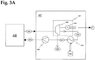
- the base load energy unit AF is only shown as a block. A possible embodiment is in Figure 3A be discussed.
- superheated steam M52 is generated from colder steam M51 (approx. 550-600 ° C / 50 bar). If necessary, a subsequent further heat exchanger can cool the synthesis gas stream further.
- the superheated steam M52 is fed into the energy unit AF, where it is used for electrical and / or mechanical energy E1.
- the remaining steam condensate M41 is returned to the processing unit AB, where it is converted into steam M51 in the third process stage P3, and this steam M51 is then converted again into superheated steam M52 in the heat exchanger / superheater A44.
- the exemplary embodiment of the energy unit AF in Figure 3A comprises a drive device A61 in the form of a steam turbine A62 or another heat engine which can be operated with superheated steam M52 for generating mechanical energy, and in the example shown a generator device A64 which is driven by the steam turbine and which generates electrical energy E1.
- the exhaust steam M53 is condensed in the condenser / economizer A63, the waste heat being removed via a suitably designed cooling circuit A65.
- the resulting condensate M41 is preferably 60-70 ° C hot, so that the water in the subsequent boiler stage A32 of the treatment plant AB does not have to be heated too much. At the same time, the water should not be too hot to avoid cavitation in the A66 pump.
- the condensate M41 is pumped with the pump A66 from an intermediate store (not shown) into the heat exchanger / boiler A32 of process stage P3, where it is evaporated again to steam M51 (approx. 250-300 ° C / 20 bar), with simultaneous cooling synthesis stage P3.
- the steam M51 is stored in a steam dome (not shown), on the one hand to separate water remaining before entering the superheater A44, and on the other hand to form a store from which the process steam M50 can be removed for the various purposes in the processing unit AB , Losses in the circuit and consumption of process steam M50 are compensated for by supplying water to the condensate store (not shown).
- part of the steam can be removed as process steam M50 in the steam turbine A62 after the high pressure stage, which is shown in Figure 3A shown as a dashed arrow is.
- process steam M50 in the steam turbine A62 after the high pressure stage, which is shown in Figure 3A shown as a dashed arrow is.
- the exhaust steam from process steam consumers such as the heat exchangers A45, A17 can also be condensed M41 and returned to the feed water M40, so that the energy cycle is as closed as possible.
- the water vapor cycles can also be guided differently through the various heat exchangers in order to achieve the highest possible efficiency in plant A.
- the products produced in synthesis stage P3 can be used as operating material M61 for a conventional fossil fuel energy system C, for example diesel generators or gas turbine generators, which can be used to cover peak loads.
- the chemical operating fluids M61 serve to achieve very high production outputs for a short time, detached from the basic system AB, AF, which is in an equilibrium state.
- the total output of the device Z can be increased from, for example, 100% constant base load production P c2 to, for example, 600% peak load production P e2 within a very short period of time.
- the M60 products can also be used for other purposes, for example for the production of fuels or as educts for the chemical industry.
- Such a device according to the invention has the advantage over conventional systems, among other things, that in the recycling unit AB, because of the closed material flow within the three-stage process, there is no need for flue gas filters and catalyst devices for cleaning the combustion exhaust gases. This leads to a reduction in the number of components of such a system, and thus to lower investment costs and operating costs.
- such a recycling unit also requires less space, since no filter systems, chimneys, etc. are required, and the volume of the material flows is lower due to the high pressure.
- an energy system C operated with operating materials M61 from the recycling plant A is provided to cover peak loads E2.
- the energy system C is designed in such a way that the carbon dioxide produced during energy generation is fed back into the cycle of the recycling system A, so that no emissions arise.
- the operating materials M61 are advantageously obtained from an intermediate storage BA of the transport / storage system B, for example a tank system or a pressure accumulator, in order to bridge peak demand.
- an intermediate storage BA of the transport / storage system B for example a tank system or a pressure accumulator
- the resulting carbon dioxide-containing residual gases M26 from the energy system B can be collected in a buffer store BB and stored.
- a possible embodiment of an energy unit C is shown in FIG Figure 4A shown.
- a drive device C11 generates electrical and / or mechanical energy E2 by means of chemical energy carriers M61 from the synthesis stage P3 of the utilization unit AB.
- Said drive device C11 can be, for example, a heat engine in which the heat generated when the operating materials M61 are oxidized to carbon dioxide is converted into mechanical work, for example for operating a generator system (not shown), or a fuel cell system in which the oxidation reaction is carried out directly Power generation E2 is used.
- Such a drive device C11 has a closed circuit, that is to say it does not cause any emissions to the atmosphere.
- the oxidation gases M27 that occur during the performance of the mechanical work, which essentially only contain carbon dioxide and possibly also water, are post-treated C12, compressed C13, and the remaining residual gas M26 is fed back into the circuit of the recycling plant AB.
- a buffer BB is provided, as in Figure 4 shown.
- the system C of the device Z according to the invention can be arranged separately from the recycling system A.
- the thermal or electrical energy-generating oxidation reaction takes place in the drive device C11 with pure oxygen M31 instead of with air.
- oxygen M31 instead of air avoids the formation of nitrogen oxides on the one hand due to the absence of atmospheric nitrogen in a thermal-chemical reaction at high temperatures, but above all only carbon dioxide and water vapor remain in the resulting oxidation gases M27.
- the resulting gases can also contain certain proportions of carbon monoxide and unreacted fuel. These can also be fed into the recycling system A without problems.
- the reaction products M27 of the energy-generating oxidation reaction are essentially gaseous.
- the corresponding oxidizing gas mixture is now compressed C13 to reduce the volume.
- the oxidizing gas mixture M27 can be cooled before and / or after compression.
- Water M41 is condensed out and separated, leaving only carbon dioxide in the residual gas M26, possibly with proportions of carbon monoxide and unreacted fuel.
- the residual gas M26 is now fed to the first process stage P1 of the recycling unit AB of plant A, so that a closed material cycle results.
- the residual gas M26 can also be led into the second process stage P2 or the third process stage P3, which is shown in Figure 4 is indicated by dashed arrows.
- liquid or gaseous hydrocarbons and hydrocarbon derivatives can be produced from carbon-containing materials M11 in a device Z according to the invention, and the resulting high-quality operating medium mixture M61 is subsequently converted into electrical energy E2.
- the carbon dioxide produced is recycled and partially or completely converted back into fuel M61 in recycling plant A. In this way, the effective carbon dioxide emissions of the peak load generator system C can be greatly reduced or even avoided altogether.
- the drive device can also be operated without problems in combination operation with hydrogen M32 as a further operating material.
- the hydrogen content leads to a reduction in the accumulated residual gas quantity M26 after the heat exchanger / condenser and compressor, since only water is produced when hydrogen is oxidized with oxygen.
- FIG Figure 5 Another advantageous embodiment of a device Z according to the invention is shown in FIG Figure 5 shown.
- this includes both a base load energy unit AF and a peak load energy system C.
- a recycling method according to the invention chemical energy in the form of molecular hydrogen is introduced into the method in larger quantities.
- a device Z according to the invention is, for example, in FIG Figure 6 (a) shown schematically.
- the recycling plant A picks up matter in the form of carbon-containing starting materials M10, as have already been discussed above.
- Carbon dioxide M33 is also suitable as a carbon source.
- the primary source of energy is the chemical energy of the molecular hydrogen M32.
- hydrogen serves to reduce the starting materials, and on the other hand, oxidation with oxygen leads to the supply of thermal energy.
- Molecular hydrogen M32 can be produced from water by electrolysis, which also produces molecular oxygen M31. Electrical energy E3 can be converted into chemical energy in this way.
- the gaseous molecular hydrogen has a significantly lower energy density compared to liquid fuels, but also compared to gaseous hydrocarbons, which means that it has so far not been able to establish itself as a fuel for vehicles.
- the chemical energy of hydrogen can be efficiently converted into chemical energy in the form of high-quality hydrocarbons and other products.
- the oxygen M31 obtained during the electrolysis is also advantageously used to introduce the entire chemical energy into the process, or a maximum of the electrical energy inserted into the electrolysis.
- a system D provides molecular hydrogen M32 and oxygen M31.
- the electrical energy E3 for the electrolysis reaction preferably comes from regenerative energy sources (wind power, solar energy, water energy, etc.).
- This has the great advantage that an inherent disadvantage of wind turbines DA and solar energy systems DB can be overcome, namely the cyclical energy production, which cannot always be guaranteed due to the dependence on external factors. This leads to correspondingly low achievable market prices for the electrical energy generated.
- the hydrogen, and if possible also the oxygen, is then used in a process according to the invention, for example in order to produce easier-to-handle liquid operating materials with a higher energy density, or other high-quality products.
- the energy of the energy generation units DA, DB of the system D is transported as electrical current E3 to the electrolysis unit DC, which is located at the location of the recycling system A and in which hydrogen M32 and oxygen M31 are generated locally. Part of the oxygen is not required and can be used for other purposes, for example in an energy system C of the invention Device Z.
- Intermediate storage units DE, DF for example in the form of pressure tanks, serve as buffers to compensate for the fluctuating energy production of the energy generation units DA, DB.
- the recycling plant A produces high-quality hydrocarbons and other synthesis products M60, as well as energy E1 if necessary, residues M90 are continuously removed from the system.
- Water can also be easily removed from the system, for example by condensation M41.
- water serves primarily as an oxidizing and gasifying agent if no oxygen is available.
- water removed from the system M41 also serves as a sink for oxygen. This is particularly relevant if the system absorbs large amounts of M33 carbon dioxide as a carbon source.
- a recycling process according to the invention can also produce high-quality and high-energy hydrocarbon products M60 from comparatively low-energy carbon sources.
- the method can in principle only be carried out using pure carbon dioxide as the carbon source. Since the supplied electrical energy comes directly or indirectly (wind power, hydropower) from the sun, this results - from a fundamental point of view - as it were an artificial photosynthesis, namely the generation of carbon compounds from carbon dioxide, water and sunlight.
- the combination of the recycling plant A with an energy plant C is optional.
- FIGS Figures 7 (a) to (d) The difference in the performance spectrum of a device Z according to the invention in comparison with a conventional power plant operated with carbon-containing operating materials is shown in FIGS Figures 7 (a) to (d) explained in more detail.
- Figure 7 (a) shows schematically the performance profile of a conventional thermal power plant.
- the vertical axis represents the power P and the horizontal axis the time t.
- the power plant has an added heat content P a , that is, the thermal energy or power contained in the fuel as chemical energy, and an effective thermal power P b , that is, the thermal energy per unit of time that can be effectively converted into electrical or mechanical energy.
- P a the thermal energy or power contained in the fuel as chemical energy
- P b effective thermal power
- the electrical power requirement P e in a conventional power grid varies both during the day and during the week.
- the total nominal power of such a power plant must be aligned to the peak load. This means that the dimensioning of the system is larger because of the peak power required than would actually be necessary due to the average total power.
- Such a device Z converts a constant part of the chemical energy supplied in the form of the carbonaceous materials M10, M11 into thermal energy in the form of water vapor, which is then converted into electrical energy P f , for example with a steam turbine of the base load energy unit AF ,
- a further portion of the chemical energy supplied in the form of the carbon-containing materials M10, M11 is converted in the synthesis stage P3 of the utilization unit AB with a constant production output P g into chemical energy in the form of high-quality carbon-containing operating materials M61, for example diesel-like products or gaseous products such as propane.
- These operating materials can be stored in any quantity BA and / or as in Figure 2 executed over short or long distances.
- Figure 7 (d) shows schematically the profile of the total power P e of a device according to the invention over the course of a week.
- the peak load energy system C generates electrical energy from the chemical operating materials M61 during the peak load requirement during the working days, which can then be fed into an energy network at a correspondingly high price.
- the need for chemical supplies M61 significantly exceeds the production output P g of the recycling plant A, which is marked with (-). This above-average consumption is taken from the BA operating fluid store.
- the demand drops sharply and the production output P g exceeds the demand P e , which is marked with (+).
- the fuel supply BA is refilled.
- the energy system C can be shut down to a minimum power level, as in Figure 7 (d) shown, or the energy unit C is completely decommissioned, so that the base load P c is completely covered by the base load energy unit AF.
- a device therefore has the essential advantage that only a part P f of the constant effective power P d is obtained in the form of thermal power, which must be immediately converted into electrical and / or mechanical energy, as in a conventional power plant.
- This part P f can be used to deliver the power for the base load base P c .
- Another part P g of the effective power P d is temporarily stored in the memory BA in the form of operating materials M61.
- the demand (P e - P f ) which exceeds the thermal power of the base load energy unit AF can then be met by the peak load energy system C from the operating fluid storage BA.
- a device Z according to the invention can be designed with a significantly smaller installed thermal output in order to be able to cover a specific requirement profile, for example 75% or 50% of the thermal output of a comparable conventional power plant. This leads to significantly lower investment costs.
- a device according to the invention can be designed and optimized such that the power P f generated directly from thermal energy is reduced in favor of the power P g generated from the operating materials M61.
- Such a variant is in Figure 7 (c) shown.
- Such a device according to the invention can cover a significantly higher amount of energy when covering a reduced base load base P c2 to save. The corresponding stored energy can finally be used to generate peak load power P e2 , which can then be sold at a higher price.
- FIG. 8 A first possible variant of the construction of a plant A for the thermal-chemical utilization of carbon-containing solids with a method according to the invention or in a device according to the invention is shown in Figure 8 shown schematically.
- the recycling system A of the device Z according to the invention comprises a recycling unit AB with three sub-units AC, AD, AE for carrying out the three process stages P1, P2, P3 of the method according to the invention, which are connected to form a closed circuit in such a way that they form a closed, cyclical gas stream allow.
- the processing unit AH only the silo A91 for the preparation of the carbon-containing material M11 prepared for the process is shown. From the discharge unit AG, only the slag storage A92 is shown.
- the recycling plant A may or may not comprise an energy unit (not shown). This is not relevant for the functionality of the recycling process.
- the three subunits AC, AD, AE of the utilization unit AB are connected to form a closed circuit in such a way that they allow a closed, cyclical gas flow.
- first process stage P1 pyrolysis stage
- first subunit AC carbon-containing starting material M11 is pyrolyzed under pressure, resulting in pyrolysis coke M21 and pyrolysis gases M22.
- second process stage P2 gasification stage
- second subunit AD pyrolysis coke M21 is gasified to synthesis gas M24, which is finally in a third process stage P3 (synthesis stage) or the third subunit AE to hydrocarbons and / or solid, liquid , or gaseous products M60 is reacted.
- the carbon-containing starting materials M11 to be processed are continuously fed into the circuit from a feed device AH, P6 via the first process stage P1.
- the products M60, M61 generated from the synthesis gas M24 are continuously withdrawn from the third process stage P3.
- the various residues M91, M92, M93 are continuously removed from the cycle.
- a large number of carbon-containing materials can be used as the starting material M11 for a recycling process according to the invention, in particular waste, biomass, coal and other heterogeneous materials such as contaminated soil, but also already deposited waste, for example from landfills. This enables the environmentally friendly and cost-effective dismantling of open landfills.
- Solid-liquid petroleum-containing materials that are difficult to use such as oil shale, oil sand, or oil sludge, can also be used in a method according to the invention.
- Carbon-containing by-products of the chemical or petroleum industry can also be used as additives M12, which otherwise cannot be used any further and may even have to be flared.
- the calorific value of the raw materials, the carbon content, water content, as well as the content of non-combustible residues such as metal, glass and ceramics can vary widely.
- the starting material can be shredded to a piece size suitable for a particular recycling plant, the preferred piece size being derived from the consistency of the material and from the specific design of the first pressure reactor or the reactor-internal delivery system. For processing with a moving grate, for example, a piece size of approx. 5-10 cm is well suited.
- the first process stage P1, AC comprises a first pressure reactor A13, in which pyrolysis of the carbon-containing starting material M11 takes place under pressure.
- the starting material M11 is introduced into the pressurized pyrolysis reactor A13 via a suitable pressure lock A11.
- the pyrolysis reactor A13 consists of a horizontal pressure body A14, in which the lumpy material is conveyed horizontally along the reactor during the pyrolysis by means of a schematically illustrated feed grate A15 with grate plates moved to and fro.
- Any other conveyor device suitable for the continuous feed of the starting material to be processed can also be used, for example roller grates, chain conveyors, screw conveyors, etc.
- a rotary kiln can also be used.
- the material is continuously transported through the pressure reactor A13 at a temperature of approx. 300-800 ° C and a pressure of 1 to 60 bar and pyrolysed with the exclusion of oxygen.
- the temperature is selected such that, in addition to maintaining the pyrolysis reaction, the desired operating pressure is maintained, on the one hand due to the expansion of the gases due to the temperature, and on the other hand due to the new production of pyrolysis gases.
- a minimum temperature of 450 ° C ensures a constant reaction of free oxygen compounds during pyrolysis.
- An operating temperature of 500-600 ° C and an operating pressure between 5 and 25 bar are particularly suitable.
- Process steam M50 also serves to maintain the operating temperature of the first reactor.
- An external heat supply such as a heat exchanger or an external heater can also be present. The latter is also advantageous when starting up the recycling plant A from the cold state.
- Return gas M25 from the third process stage (synthesis stage) P3 is fed to the first pressure reactor A13 after passing through a compressor A42.
- the return gas M25 mainly contains carbon dioxide, as well as water vapor and unreacted carbon monoxide and hydrogen in the synthesis stage, as well as residual contents of low molecular weight hydrocarbons.
- additional carbon with a high calorific value can be introduced into the reactor A13, for example in the form of coal or heavy oil.
- additives M12 can be added to the starting material M11 beforehand, or can be introduced separately into the reactor A13.
- the mixing of viscous additives M12 with solid starting material M11 facilitates the conveyance of viscous material within the reactor. Liquid M12 additives also increase the amount of pyrolysis gas, and thus the operating pressure.
- Pyrolysis coke M21 which consists essentially of solid carbon and inorganic residues, is produced during pyrolysis in the first process stage P1.
- the pyrolysis coke M21 is discharged at the end of the pressure reactor A13.
- the pyrolysis gases M22 produced during pyrolysis contain both gaseous and solid and liquid materials at room temperature. The composition of pyrolysis gases M22 naturally depends heavily on the starting materials and may also contain pollutants.
- the pyrolysis coke M21 is conveyed under pressure into the pressure reactor A21 of the second process stage P2.
- a closed screw conveyor for example, is again suitable.
- a pressure lock can also be provided.
- the pyrolysis gases M22 are also fed into the second pressure reactor A21 via a separate transport line.
- a compressor A41 arranged in the transport line conveys the pyrolysis gases into the second pressure reactor A21, which is at a higher operating pressure.
- the operating temperature is between 600 and 1600 ° C.
- the solid carbon is gasified in pyrolysis coke M21, using carbon dioxide and optionally oxygen and / or water vapor as the gasifying agent, to carbon monoxide and hydrogen, according to reactions I, II and III.
- the carbon dioxide comes primarily from the return gas M25. Additional M33 carbon dioxide can also be fed into the circuit.
- the water vapor primarily consists of the residual moisture of the raw material M11. Process steam M50 can also be fed.
- the thermal energy necessary for the course of these endothermic pyrolysis reactions comes, for example, from a partial oxidation of the solid carbon (reaction III) with oxygen M31 passed into the second pressure reactor A21.
- the exothermic water gas shift reaction IV can also contribute to this.
- the ratio between carbon monoxide and hydrogen which is important for the later synthesis in the third process stage P3 is given by the water gas shift reaction IV and can be influenced on the right-hand side by adding process steam M50. However, it is advantageous to add the total amount To keep water in the system as low as possible and instead introduce additional M32 hydrogen directly into the third process stage.
- the second process stage likewise comprises a pressure body A22, in which the pyrolysis coke is conveyed within the reactor A21 by a feed grate A23.
- a feed grate A23 in which the pyrolysis coke is conveyed within the reactor A21 by a feed grate A23.
- other conveyor systems are also possible, as have already been discussed for the first pressure reactor A13. This has the advantage that the pyrolysis coke can be processed in the second process stage without further preparation.
- the second reactor can also be designed differently.
- the pyrolysis coke could be crushed or ground beforehand, which then enables gasification of the coke in an eddy current or entrained flow.
- this variant has the disadvantage that the particles have a shorter retention time in the reactor, which requires a more homogeneous material feed and preparation.
- such systems require more precise and faster control of gas flow speed and other process parameters.
- the reactive surface of lumpy pyrolysis coke is comparatively small compared to a reaction in the eddy current, which is also possible, but this is compensated for by the comparatively long residence time in reactor A21 due to the high mass capacity of the pressure reactor.
- Another advantage is the easier scalability. By simply extending the pressure reactor or a By enlarging the cross-section, the capacity and thus the turnover can be increased without the relevant process parameters such as pressure or temperature having to change. However, reactors with flight or eddy current cannot be scaled up easily and easily.
- the oxygen M31 necessary for the partial oxidation and optionally the process steam M50 are blown into the ember bed formed by the pyrolysis coke, whereby the necessary thermal energy is generated and the reactor A21 is kept at operating temperature.
- air could also be used, but the inert atmospheric nitrogen inflates the gas material stream circulating within the recovery unit and is difficult to remove. This significantly reduces the efficiency of the system, so that pure oxygen is always preferable.
- the absence of nitrogen in the system also prevents the formation of nitrogen oxides.
- the pyrolysis gases M22 are in Figure 8 Embodiment of a recycling plant A shown is blown into the gas phase above the ember bed in the pressure reactor A21, where the polyatomic molecules contained in the pyrolysis gases M22 are cracked and disassembled very quickly at the prevailing high temperatures.
- the synthesis gas M24 formed in the second process stage therefore essentially no longer contains any organic molecules and can be used for the Fischer-Tropsch synthesis in the third process stage. Pollutants such as dioxin are also broken down.
- the oxygen supply M31 into the ember bed and the point of entry of the pyrolysis gases M22 into the pressure reactor are advantageously chosen so that no dioxins can form, which can be achieved by a suitable spatial separation. Likewise, no oxygen should be present in the synthesis gas emerging.
- unproblematic raw materials such as wood chips or straw or other unpolluted biomass
- residues M91 remain in the form of ash and inert residues as well as possibly unprocessed carbon. If slagging is desired, additives can be added that lower the ash melting point. For this purpose, lime powder can be added to the starting material M11, for example.
- the slag is removed from the second pressure reactor A21 via a suitable pressure lock A28 from the pressure area of the recycling plant AB.
- the second process stage can alternatively be designed so that unreacted pyrolysis coke is conveyed to the beginning again at the end of the pressure reactor and can thus run through the reactor a second time. This enables a shorter design of the pressure reactor.
- the synthesis gas stream M24 is discharged from the second pressure reactor A21, and a main part M24a is passed through a suitable heat exchanger A44, where the gas stream producing process steam M50 for in-process purposes and / or steam M52 for energy generation in an energy unit AF (not shown) is cooled to a temperature which is suitable for the Fischer-Tropsch synthesis in the third process stage P3. Due to the lower temperatures, the pressure drops and the equilibrium of reactions I, II and IV shifts, as a result of which the proportion of carbon dioxide in the synthesis gas increases again. Solid carbon M94 can also separate from the gas stream in the form of graphite. The carbon M94 can be used as the starting material M11, M12 be recycled, otherwise used as a valuable material, or removed from the system as residual material.
- the synthesis gas stream M24a is then fed to a cyclone A47, where dust M92, mainly consisting of residual coke and ash, is separated off.
- the residual dust M92 can be returned to the first pressure reactor A13 or the second pressure reactor A21, or it is processed and / or disposed of.
- a cyclone another suitable gas flow cleaning device can also be used.
- the carbon M94 arrives with the synthesis gas stream in the Fischer-Tropsch reactor A31, where it can be removed or filtered off together with the carbon formed as a by-product in the Fischer-Tropsch reaction.
- the synthesis gas M24 is then fed via a pressure regulator A48 to a third pressure reactor A31 of the third process stage P3, in which a Fischer-Tropsch synthesis is carried out.
- Pressure regulation A48 reduces the pressure to the value desired for the third process stage.
- additional hydrogen M32 can be fed into the Fischer-Tropsch reactor A31.
- the necessary solid-state catalysts M37 are also supplied.
- Suitable for the synthesis stage are, for example, low-temperature Fischer-Tropsch processes, which are operated, for example, at 210 to 250 ° C. and, above all, deliver diesel-like products and long-chain components in the form of waxes. The latter can then be used for example by hydrocracking.
- High-temperature processes with temperatures between 320 and 350 ° C in turn supply considerable amounts of methane, short-chain alkanes and alkenes, as well as higher amounts of light petrol.
- tube-bundle reactors are suitable, in which the synthesis gas flows from top to bottom through cooled tubes filled with catalyst. Return gas and products leave the tube at the bottom.
- the steam M51, M50 obtained by the cooling device A32 contains considerable thermal energy, but is not yet hot enough for efficient utilization, for example in a steam turbine of an energy unit AF. It is therefore used advantageously for hot steam generation M52, for example in the heat exchanger A44, in order to increase the overall energy efficiency of the system.
- the interaction of a recycling unit AB and a further energy-generating unit AF of a recycling system A is already shown in FIGS Figures 3 to 5 been received.
- the gas stream M25 which leaves the Fischer-Tropsch reactor A31, contains, in addition to unreacted carbon monoxide and hydrogen gas, water vapor, carbon dioxide and gaseous reaction products M60.
- a portion of volatile M60 hydrocarbons can be condensed out, for example, using a cooling column (not shown).
- Water M41 can also be condensed out and thus removed from the return gas and thus from the material flow.
- Part M25b can be separated as a process product from the remaining return gas stream.
- the remaining return gas stream M25a is compressed in a compressor A42 and fed back into the first reactor A13.
- the cyclical conveying of the gas flow within the recycling plant A takes place primarily due to the prevailing pressure differentials along the circuit. These are primarily generated by the two compressors A41, A42. Depending on the design of the system, one of the two compressors can be omitted, which lowers the overall cost of the system. If the plant contains only one compressor (as for example in the second exemplary embodiment of a recycling plant in Figure 9 ), the arrangement in front of the first reactor A13 has the advantage that the corresponding compressor A42 has to compress a smaller gas volume than a compressor A41 between the first and second process stages, where the pyrolysis gases are added and the total volume is larger due to the higher temperature , or even between the second and third process stages.
- compressor A41 If the compressor A41 is dispensed with, there is only a slight pressure drop between the two reactors A13, A21, so that the first and second process stages run essentially at the same pressure. The gas flow then runs from compressor A42 via first A13, second A21 and third reactor A31 back to compressor A42. If, on the other hand, the compressor A42 is dispensed with, the pressure within the third reactor A31 and first reactor A13 is essentially the same.
- a compressor can also be arranged between the second and third process stages. For reasons of entropy, at least one compressor or other funding must be available to promote the gas flow and to keep the process going.
- pressure accumulators can be provided along the gas circuit M22, M24, M25 (not shown). Similarly, it is also possible to provide a buffer for the M21 pyrolysis coke.
- the compressor A41 can produce a pressure difference of several bar with reasonable energy expenditure.
- the first process stage could then be operated at a significantly lower pressure than the second process stage.
- the first process stage can even be carried out under normal pressure or even under pressure.
- FIG. 8 A possible method for starting up a recycling plant A as in is now discussed below Figure 8 shown.
- the circuit and the three process stages are flushed and filled with an oxygen-free gas, advantageously with carbon dioxide and / or carbon monoxide and / or hydrogen gas or mixtures thereof, that is to say synthesis gas.
- the second pressure reactor A21 which was previously filled with coke, is then heated, for example with gas burners.
- the second reactor is separated from the circuit by closing the corresponding connections.
- the conveyance A23 of the coke within the pressure reactor A21 is not yet switched on.
- a temporary short circuit between the heat exchanger A44 and the pressure reactor A21 can be provided in the circuit (not shown) in order to circulate the heated gas in the system and to be able to heat the entire system section evenly.
- the pressure is also increased to the setpoint.
- the first pressure reactor A13 which was also previously filled with coke, is separated from the circuit and heated to the intended operating temperature of the first process stage.
- the pressure is also brought to the desired value for the first process stage.
- Material delivery A15 in the first reactor remains switched off.
- heating should preferably take place without starting material, since pyrolysis of the starting material below a minimum safe operating temperature of 450 ° C. can lead to the formation of explosive mixtures.
- the coke on the other hand, has already been pyrolyzed and only serves to supply coke to the second process stage when the cycle is started later.
- the Fischer-Tropsch reactor A31 is also separated from the circuit and brought up to operating conditions. After the operating conditions in the various process stages of the recycling plant have been reached, the various conveyor systems A15, A23 are started up slowly, the circuit is opened, and the compressors A41, A42 are put into operation, so that the recycling plant AB finally comes to a state of equilibrium with the desired operating parameters.
- FIG Figure 9 Another embodiment of a utilization unit AB of a device Z according to the invention is shown in FIG Figure 9 shown. For the sake of clarity, the boundary of the recycling unit AB has not been shown.
- the branched synthesis gas stream M24b is not fed directly back into the first reactor A13, but instead is led through a heating device A16 of the pressure reactor A13 and then combined again with the synthesis gas M24a.
- a further heating device A17 can be provided, which is operated with process steam M50.
- a heat exchanger A45 is arranged in the return gas stream M25a and serves to heat the return gas stream M25a by process steam M50.
- the return gas stream also serves to supply heat to the first pressure reactor A13.
- no pressure reduction is provided before the third pressure reactor A31.
- the pressure control in the third process stage takes place directly via the pressure control in the second process stage and the subsequent pressure drop due to the cooling of the synthesis gas stream M24 in the heat exchanger A44, as well as the compressor A42.
- the low-temperature Fischer-Tropsch reactor of the third process stage is replaced by a high-temperature Fischer-Tropsch reactor in which the catalyst is present as a swirling dust.
- the gaseous, short-chain hydrocarbons which are preferably formed in the high-temperature Fischer-Tropsch synthesis and remain in the return gas after a first condensation stage are separated from the smaller molecules of the return gas, such as carbon dioxide, carbon monoxide and hydrogen, by means of permeation gas filters.
- Such systems are known for example from the petrochemical industry for the purification of natural gas. In the present case, they serve to generate a first, hydrocarbon-rich gas phase and a second, low-hydrocarbon gas phase.
- the hydrocarbon-rich gas phase is further used as fuel for a second generator stage to generate electrical energy, or is processed into liquid gas and natural gas.
- the low-carbon and carbon dioxide-rich second gas phase is sent back into the circuit as return gas.
- the third process stage P3 contains a liquid-phase methanol synthesis reactor instead of a Fischer-Tropsch reactor.
- the liquid phase methanol synthesis known from the prior art is particularly suitable for producing methanol in high yield from synthesis gas with a higher proportion of carbon dioxide.
- the synthesis takes place in a "slurry bubble column reactor" in which the synthesis gas is blown into a slurry of the powdery catalyst in an inert mineral oil.
- the reaction is highly exothermic, so a cooling device is necessary.
- the gaseous methanol produced leaves the pressure reactor together with unreacted synthesis gas. After the entrained mineral oil and catalyst have been separated off, the methanol is condensed out.
- Methanol is a valuable basic product for the chemical industry and can also be used as a fuel. Methanol can also be used as an additive to gasoline, for example in Germany a proportion of up to 3% methanol in vehicle gasoline is permitted. The methanol can also be used in particular as operating medium M60 for a second generator stage.
- the method according to the invention shown is based on a cyclic material flow through the three process stages P1, P2, P3 of the utilization unit AB, carbon-containing Starting material M11 is fed into the circuit as a carbon supplier and energy source and the products of the synthesis stage are branched off as valuable materials M60 or as operating materials M61 for the energy system C of the device according to the invention.
- the slag M91 and other residual materials M92, M93, M94, and water vapor in the return gas M25 are continuously removed from the circuit.
- the steam produced in the heat exchangers is used on the one hand as process steam M50 for the operation of the system, thus increasing the efficiency and effectiveness of the system.
- the hot steam M51, M52 can be used for energy production in an energy unit AF.
- an energy-rich product M60, M61 namely the different fractions of the Fischer-Tropsch stage, is produced from an energy-rich but heterogeneous and difficult-to-use solid starting material M11. These can then be used further, for example as liquid fuels or as educts for the chemical industry.
- the energy required for the operation of the recycling plant AB comes from the partial oxidation reaction in the second process stage, with an excess of the chemical energy generated there (in the form of the synthesis gas) later in the exothermic Fischer-Tropsch reaction of the third process stage again in thermal energy Form of steam M50, M51 is converted.
- superheated steam M52 is generated from the carbon-containing starting material M11 for continuous operation of a base load energy unit AF, and fuel M61 for flexible operation of a peak load energy unit C.
- the pressure and temperature in the third reactor A31 are the decisive parameters for the production of the hydrocarbons and other products in the third Fischer-Tropsch stage P3.
- the pressure can be checked briefly with the A42 compressor by increasing or decreasing its output.
- the temperature can in turn be controlled by the cooling capacity of the A32 heat exchanger.
- the pressure can be controlled via the pressure in the synthesis gas stream M24, on the one hand by changing the operating pressure and the temperature in the second process stage, and on the other hand by controlling the cooling capacity of the heat exchanger A44, and thus the temperature and pressure drop in the synthesis gas stream M24.
- the control of a recycling plant A is comparatively simple, since the plant runs in an equilibrium state with feedback, and to control a few less relevant parameters, a plurality of parameters, the individual operating parameters of the various plant components, which can affect the balance slowly or quickly, can be changed.
- the recycling method according to the invention is preferably carried out with an increased carbon dioxide content. Among other things, this shifts the reaction equilibrium IV to the left (more carbon monoxide). Such an increased carbon dioxide content is made possible with the highest possible absolute amounts of carbon monoxide and thus processing power increased operating pressure of the treatment plant between 10 and 60 bar. Higher or lower pressures are also possible, but less efficient.
- the recycling plant can be optimized with regard to various aspects. For example, if carbon dioxide-neutral biomass, such as wood chips, is to be used in the third process stage to produce valuable materials such as diesel and gasoline-analogous hydrocarbons and waxes, etc., the process is based on the best possible relationship between the costs for the biomass and the current ones Operation and the value of the recyclables produced. However, less attention needs to be paid to the emission of carbon dioxide, since it is carbon dioxide-neutral biomass. In order to further improve the ecological balance, the external energy supply (electrical power etc.) can be reduced, with possibly increased biomass consumption.
- the external energy supply electrical power etc.
- the system is operated in such a way that as little carbon dioxide as possible has to be removed from the cycle and released into the environment. This may then lead to an increased need for external energy.
- the recycling plant can also be optimized for maximum throughput of starting material, so that possibly unprocessed pyrolysis coke leaves the third process stage together with the slag.
- the pyrolysis coke which is not problematic from an environmental point of view, can then be deposited together with the slag.
- Such a variant is advantageous, for example, if large amounts of contaminated material are to be rendered harmless in a carbon dioxide-neutral manner.
- the operating temperature of the second process stage P2 can also be optimized.
- the operating temperature of the second process stage P1 of the processing unit AB can be reduced in order to increase the throughput in the second reactor A21. This may then result in certain volatile substances in the pyrolysis gas M22 no longer being cracked and in the synthesis gas M24 entering the Fischer-Tropsch reactor A31.
- benzene from the starting material such as heavy oil, can reach the Fischer-Tropsch synthesis products in smaller quantities. These materials remain there as part of a liquid M61 fluid, but can also be separated if necessary.
- FIG 10 schematically shows an advantageous embodiment of a recycling unit AB.
- a heat exchanger A46 is arranged, which serves to heat the pyrolysis gases M22 to the operating temperature of the second process stage with process steam M50 before entering the second pressure reactor A21. It is also possible to charge the A46 heat exchanger with hot M24 synthesis gas.
- the compressor A43 is arranged in the transport line of the synthesis gas M24, after a heat exchanger A44. Although the mass flow is greatest at this point in the system, the gas volume to be managed for the compressor A43 is smaller due to the greatly reduced temperature after the heat exchanger A44, and the operating temperature for the compressor is more favorable because it is lower.
- FIG Figure 11 A further advantageous embodiment of a utilization unit AB of a device Z according to the invention is shown in FIG Figure 11 shown, which is particularly suitable for the production of liquid fuels M61 from unpolluted biomass such as wood chips.
- the pyrolysis gases M22 are not passed into the second process stage P2 but into the third process stage P3, the synthesis gas M24 not into the third process stage P3 but into the first process stage P1, and the return gas M25 not into the first process stage P1 but into the second process stage P2.
- the hot synthesis gas stream M24 heats the pyrolysis material and maintains the operating temperature.
- the pyrolysis gas stream M22 emerging from the first process stage then contains, in addition to the actual pyrolysis gases, also the synthesis gas fraction from the second process stage, which therefore makes a loop over the first process stage.
- the synthesis gas component in the pyrolysis gases M22 is reacted, while those pyrolysis gas components which do not already condense in the heat exchanger A45 M23 dissolve in the liquid phase of the synthesis reactor A31. Since the purity requirements are not particularly great when the products M60 of the third process stage are used directly as fuel or as operating material for the second drive device C11, cracking of the pyrolysis gases can be dispensed with.
- the fuel or operating fluid M61 is then cleaned to remove unsuitable residues such as organic acids etc.
- the condensed portions M23 of the pyrolysis gas which have a low melting point and boiling point and contain a significant portion of tar, can advantageously be fed to the second process stage as a solid or liquid additive M23.
- the return gas stream M25 is then compressed A42, heated A46 and introduced into the second process stage P2, so that a cycle is formed again. Since it is not necessary to crack the gases introduced into the A21 pressure reactor, the second process stage can be operated at a lower operating temperature.
- Figure 12 shows an embodiment of a utilization unit AB, in which the first and second process stages P1, P2 are carried out in a common pressure reactor A24.
- the pyrolysis takes place in a first chamber A25 of the reactor A24, the gasification in a second chamber A26.
- the two chambers A25, A26 are formed by a partition A27 arranged in the pressure reactor A24, with a passage through which a common conveyor system conveys the pyrolysis coke M21 and the pyrolysis gas M22 flows.
- the partition A27 serves primarily to thermally insulate the two chambers A27, A26, so that different operating temperatures can be reached in the two process stages. It is also possible to equip such a common pressure reactor with more than two separate chambers.
- water M40 can be used as an additional expansion means in an advantageous variant of such a drive device.
- a certain amount of water is injected into the cylinder after the ignition of the combustion process, for example after the compressed fuel-air mixture has auto-ignited in a diesel engine.
- This water which is preferably finely atomized, is then evaporated by the thermal energy of the exothermic oxidation reaction.
- the resulting increase in gas pressure or gas volume due to the water vapor thus contributes to the generation of the kinetic energy, however at the same time the temperature of the total mixture of combustion gases and water vapor drops.
- this is unproblematic or even desirable because the higher energy density of a reaction with pure oxygen results in significantly higher reaction temperatures, which improves the thermodynamic efficiency but can also put more stress on the parts of the drive device C11.
- the water can also be introduced as M50 steam.
- a certain proportion of liquid water can also be mixed with the liquid fuel.
- superheated steam also acts as an additional oxidizing agent in addition to oxygen.
- drive devices C11 for a peak load energy system C of a device Z is described and explained in more detail, using the example of an internal combustion engine in the form of a piston engine with a cylinder.
- drive devices C11 designed as internal combustion engines can also be designed as turbines or Wankel motors, etc.
- the hot combustion gases are used in accordance with the functional principle of the respective type of internal combustion engine for the performance of mechanical work, for example for operating a generator system, and are partially relaxed.
- the M27 oxidizing gas then leaves the combustion chamber.
- a drive device C11 as a heat engine with external combustion, for example as a steam engine or steam turbine.
- the internal combustion engine C11 shown has a cylinder C22 and a piston C23 movably arranged therein, which together form a closed combustion chamber C21.
- a feed device C27 shown only schematically oxygen M31 is introduced into the expanding combustion chamber C21 in a first cycle.
- the oxygen M31 is then compressed in a second cycle, and at the end of the second cycle, the operating medium M61 is introduced into the combustion chamber C21 and burned using a feed device C29.
- the expanding combustion gases M27 perform mechanical work
- the partially relaxed combustion gases M27 are removed from the combustion chamber C21 by a ventilation device C24 (not shown in more detail).
- the hot oxidation gases M27 which essentially consist only of carbon dioxide and water vapor, are then cooled in a downstream heat exchanger C12. This reduces the volume of these M27 oxidizing gases. As a result of the cooling, most of the water M41 condenses out and is separated off.
- the remaining residual gas M26 which essentially only consists of carbon dioxide and possibly residual carbon monoxide and unreacted operating materials, is compressed in a compressor C13 arranged in series and collected in a pressure accumulator BB.
- the condensation stage C12 before compression reduces the undesirable formation of condensate droplets in the compressor C13.
- the illustrated internal combustion engine C11 has no emissions. Since the device is not operated with air or similar gas mixtures as the oxidizing agent, no air-specific pollutants such as nitrogen oxides can arise. The water generated during the combustion is unproblematic and can be separated. The carbon dioxide is in as residual gas M26 managed the cycle of the recycling plant AB. Unburned parts of the fuel either condense out together with the water and are separated off, or are compressed together with the carbon dioxide. The oxidation gases M27 from the drive device C11 can also be passed directly into the first or second process stage without cooling.
- peak load energy unit C is spatially separated from the recycling plant A, and if direct return of the residual gases M26 is not practical, then these can also be compressed to a very high degree and transported back from the energy plant C to the recycling plant A under high pressure in pressure accumulators BB.
- FIG Figure 14 A further possible embodiment of a drive device C11 configured as an internal combustion engine is shown schematically in FIG Figure 14 shown.
- water M40 is introduced into the combustion chamber C21 by means of a feed device C28 which is only shown schematically. This is preferably done in such a way that a certain amount of water, liquid or vapor, is injected into the combustion chamber C21 and finely distributed during or after the combustion reaction. This water is heated by the heat of combustion, whereby the total gas volume in the combustion chamber C21 increases, and thus also the gas pressure or gas volume available for the performance of the mechanical work. Accordingly, the amount of fuel can be reduced while maintaining the same performance.
- water M40 can also be introduced into the oxidizing gas stream M27 when it has left the combustion chamber C21.
- Such a variant has the advantage that the combustion reaction in the combustion chamber can proceed efficiently at the highest possible temperatures, and at the same time the resulting temperature of the oxidizing gas stream is so low that the subsequent devices C12, C13 are subjected to less stress.
- the amount of water and the time of injection are coordinated with the supply of fuel M61 and oxygen M31 so that the combustion reaction can take place efficiently.
- the resulting temperature during the oxidation reaction is advantageously essentially such that the thermodynamic efficiency of the heat engine is as high as possible.
- the oxidation gases M27 are first compressed in a compressor C13 before they are subsequently cooled in the heat exchanger C12.
- This variant is also made with the internal combustion engine C11 without water injection Figure 13 can be combined, and vice versa, and can be used generally for a drive device C11.
- the energy necessary for the operation of the compressor of a drive device C11 is advantageously generated by the drive device itself.
- the achievable efficiency of the drive device decreases, but at the same time the emission-free nature of the drive device mentioned is achieved.
- the achievable power is greater with the same motor dimensions, which compensates for the loss of power.
- the compressor can be operated directly with the crankshaft of a piston-type internal combustion engine, for example, via a suitable transmission.
- the compressor can sit directly on the same shaft.
- the oxidizing gases can then be condensed directly after the expansion process and the remaining stream can be compressed.
- the oxidation gases are already precompressed after the combustion in the third cycle within the combustion chamber and are only then released by the venting device C24. If necessary, the downstream compressor C13 can also be omitted.
- Such an embodiment is also possible as a two-stroke variant, because the new loading of the combustion chamber with the reaction mixture (fuel M61, oxygen M31, water M40) can take place very quickly in a drive device.
- the combustion gases are pre-compressed and released from the combustion chamber towards the end of the stroke.
- the gaseous oxygen can be blown into the combustion chamber under high pressure at the end of the upward stroke, since comparatively little oxygen is required for a complete combustion reaction, and water is available as an additional expansion agent.
- the liquid operating fluid M61 and the water M40 as expansion medium can be injected into the combustion chamber C21 very quickly and under high pressure.
- the energy consumption for the compressor C13 can be optimized by a suitable combination with one or more heat exchangers or cooling elements, in which the gas volume can be reduced by releasing thermal energy of the reaction gases to an internal or external heat sink.
- the heat exchanger / condenser C12 can be used to generate steam, which can either be used to increase the efficiency of an energy unit AF of the recycling system, or to obtain process steam M50 for operating the recycling unit AB of the recycling system.
- Figure 15 shows a particularly advantageous embodiment of a peak load energy system C, with a drive device C11, which is designed as a combined gas / steam turbine.
- a drive device C11 which is designed as a combined gas / steam turbine.
- fuel M61 is burned with oxygen M31 in a burner C25, forming a very hot combustion gas.
- Water is introduced into the combustion chamber C21, preferably as superheated liquid water with a temperature of, for example, 250 ° C. and a pressure of 50 bar. The resulting water vapor mixes with the combustion exhaust gases, so that a hot (e.g.
- oxidation gas M27a with a high proportion of superheated water vapor is produced, which emerges from the combustion chamber C21 and is converted into mechanical work in a subsequent turbine device C30, with which again a generator device C31 is driven.
- the gas mixture in the combustion chamber behaves isochorically, so that the gas pressure rises, or isobarically, so that the gas volume increases accordingly, or both the volume and the pressure rise.
- the subsequent turbine device C30 must also be designed accordingly. Suitable turbines C30 are known from the prior art and usually have several process stages. In an alternative variant, after a high pressure stage of the turbine device C30, partially released process steam M50 can be drawn off and used in another way.
- the relaxed oxidizing gas M27b is passed into a condenser / economizer C12, where the water M41 is condensed out and separated off.
- the remaining residual gas M26 which essentially contains carbon dioxide, is compressed in a compressor C13 and conveyed into the first process stage P1 of a recycling plant AB.
- the compressor C13 is advantageously driven directly by the turbine C30.
- the water M40 can also be mixed with the oxidizing gas stream M27a only after the combustion chamber C21, for example by means of a Venturi nozzle.
- the amount of water M40 and the amount of fuel mixture M61, M31 and the other selectable parameters are advantageously matched to one another in such a way that the subsequent turbine achieves the highest possible energy utilization.
- the proportion of water in the oxidizing gas mixture M27b should be as high as possible.
- the highest possible pressure drop of the gas mixture on the condenser C12 is achieved, which increases the total pressure difference across the turbine C30, and thus its efficiency.
- less residual gas M26 remains, which has to be compressed C13.
- Another advantage of introducing steam into the combustion chamber is the cooling effect of the M50 steam.
- the exothermic oxidation of the fuel mixture M61, M31 can lead to very high temperatures, up to 1000 ° C or even 2000 ° C. Such temperatures would place a great strain on the structures of the combustion chamber C21 and the subsequent turbine device C30.
- the comparatively cold water vapor is preferably introduced into the chamber in such a way that it shields the walls of the combustion chamber C21 from the very hot flame C26.
- the steam finally cools the entire gas mixture to 600 ° C to 800 ° C, which lowers the thermal load on the turbine blades and increases the service life accordingly.
- the drive device shown also differs from a conventional gas turbine, for example, in that no compressor is connected upstream of the combustion chamber.
- This allows the combustion chamber C21 to be designed much more simply than in the case of a gas turbine. Since the operating materials M61 are burned with pure oxygen M31, the achievable energy density is higher than when using air with its reduced oxygen content. In order to nevertheless increase the amount of oxygen that can be introduced into the combustion chamber C21 per unit of time, this can be pressurized in advance.
- the turbine device C30 can be designed like a steam turbine, since the temperature and pressure ranges of the oxidizing gas M27a are essentially the same.
- the drive device C11 of the energy system C remains idle. A small amount of steam keeps the C30 turbine moving while the generator device is not producing electricity. If the current requirement increases briefly, fuel mixture M31, M61 is injected into the combustion chamber C21 and ignited with an ignition device (not shown). At the same time, the amount of water M40, M50 injected is increased. The turbine C30 now starts up and the generator C31 is started up.
- the drive device C11 can also be in continuous operation, for example at 10% to 50% of the output of the base load generator system AF. When the power requirement is increased, the system C can then be brought to maximum output in the shortest possible time, for example 500% of the output of the base load generator system AF.
- a device Z according to the invention can thus adapt the overall performance very dynamically over a wide range.
- a peak load energy unit C can also have a plurality of combustion chambers C21 and / or turbine devices C30.
- the individual system parts are dimensioned and designed such that they can be efficiently broken down into individual modules, which are transported by truck and then reassembled can.
- a maximum dimensioning of the modules, which allows transport without special means of transport, is particularly advantageous.
- Such a modular device according to the invention has the advantage that it can also be created only temporarily, for example for an operating time of only a few years or even only months. As soon as there is no longer any need, it can be dismantled and reassembled at a new location.
- Such a facility is particularly useful in mining, for example, if a larger energy infrastructure has to be built in a short time in remote mining areas, which is no longer required after the end of the mining activities.
- a recycling system of a device according to the invention can be used to produce diesel fuel for vehicles and power generators of a remote open-cast mine from locally grown biomass and carbon-containing waste materials, and / or electrical energy for the operation of the infrastructure.
- the reactors of the first and second process stages can be built as horizontal reactors with a comparatively small cross-section without reducing the throughput.
- the reactor is simply lengthened accordingly in the longitudinal direction.
- the reactor can then be assembled in the longitudinal direction from several modules flanged together.
- the synthesis reactor can be scaled by using several reactors working in parallel.
Landscapes
- Chemical & Material Sciences (AREA)
- Engineering & Computer Science (AREA)
- Organic Chemistry (AREA)
- Combustion & Propulsion (AREA)
- Oil, Petroleum & Natural Gas (AREA)
- Mechanical Engineering (AREA)
- General Engineering & Computer Science (AREA)
- General Chemical & Material Sciences (AREA)
- Chemical Kinetics & Catalysis (AREA)
- Engine Equipment That Uses Special Cycles (AREA)
- Carbon And Carbon Compounds (AREA)
- Production Of Liquid Hydrocarbon Mixture For Refining Petroleum (AREA)
- Organic Low-Molecular-Weight Compounds And Preparation Thereof (AREA)
- Luminescent Compositions (AREA)
- Hydrogen, Water And Hydrids (AREA)
- Processing Of Solid Wastes (AREA)
- Coke Industry (AREA)
Abstract
In einem Verfahren zur Erzeugung von Energie (E1, E2, E4) und/oder Kohlenwasserstoffen und Methanol (M60, M61) durch Verwertung von kohlenstoffhaltigen Materialien (M10, M11) ohne Emission von Kohlendioxid in die Atmosphäre, wird in einer ersten Prozessstufe (P1) die kohlenstoffhaltigen Materialien (M10, M11) zugeführt und pyrolysiert werden, wobei Pyrolysekoks (M21) und Pyrolysegas (M22) entstehen; wird in einer zweiten Prozessstufe (P2) der Pyrolysekoks (M21) aus der ersten Prozessstufe (P1) vergast wird, wobei Synthesegas (M24) entsteht, und Schlacke und andere Reststoffe (M91, M92) entfernt werden; und wird in einer dritten Prozessstufe (P3) das Synthesegas (M24) aus der zweiten Prozessstufe (P2) mit einer Fischer-Tropsch-Synthese oder einer Liquid-Phase-Methanol-Synthese umgewandelt wird in Kohlenwasserstoffe und/oder Methanol (M60, M61), die abgeführt werden. Die drei Prozessstufen (P1, P2, P3) bilden einen geschlossenen Kreislauf bilden, wobei das Pyrolysegas (M22) aus der ersten Prozessstufe (P1) in die zweite Prozessstufe (P2) und/oder die dritte Prozessstufe (P3) geleitet wird, das Synthesegas (M24) aus der zweiten Prozessstufe (P2) in die dritte Prozessstufe (P3) und/oder die erste Prozessstufe (P1) geleitet wird, und überschüssiges Gas (M25) aus der dritten Prozessstufe (P3) als Rücklaufgas in die erste Prozessstufe (P1) und/oder die zweite Prozessstufe (P2) geleitet wird.In a process for the generation of energy (E1, E2, E4) and / or hydrocarbons and methanol (M60, M61) by recycling carbon-containing materials (M10, M11) without emission of carbon dioxide into the atmosphere, a first process step (P1 ) the carbon-containing materials (M10, M11) are fed in and pyrolysed, pyrolysis coke (M21) and pyrolysis gas (M22) being produced; in a second process stage (P2) the pyrolysis coke (M21) is gasified from the first process stage (P1), whereby synthesis gas (M24) is produced and slag and other residues (M91, M92) are removed; and in a third process stage (P3) the synthesis gas (M24) from the second process stage (P2) is converted into hydrocarbons and / or methanol (M60, M61) using a Fischer-Tropsch synthesis or a liquid-phase methanol synthesis that are dissipated. The three process stages (P1, P2, P3) form a closed circuit, the pyrolysis gas (M22) being passed from the first process stage (P1) to the second process stage (P2) and / or the third process stage (P3), the synthesis gas (M24) from the second process stage (P2) into the third process stage (P3) and / or the first process stage (P1), and excess gas (M25) from the third process stage (P3) as return gas into the first process stage (P1 ) and / or the second process stage (P2) is conducted.
Description
Die Erfindung betrifft Verfahren und Einrichtungen zur emissionsfreien Energieerzeugung durch thermisch-chemische Verarbeitung und Verwertung von festen, flüssigen und gasförmigen kohlenstoffhaltigen Materialien und Gemischen, insbesondere von Abfall, Biomasse, Kohle, und anderen heterogenen Materialien. Weiter betrifft die Erfindung Einrichtungen zur Erzeugung von elektrischer und mechanischer Energie und entsprechende Verfahren, sowie die Erzeugung von synthetischen Kohlenwasserstoffen, und deren Verwendung in solchen Einrichtungen.The invention relates to methods and devices for emission-free energy production by thermal chemical processing and recycling of solid, liquid and gaseous carbonaceous materials and mixtures, in particular waste, biomass, coal, and other heterogeneous materials. The invention further relates to devices for generating electrical and mechanical energy and corresponding methods, and also to the production of synthetic hydrocarbons, and their use in such devices.
Schon länger ist bekannt, dass Emissionen, besonders Kohlendioxidemissionen, sehr negative Auswirkungen auf das Klimagleichgewicht der Erde haben und stark zur menschengemachten Klimaerwärmung beitragen. Die Vermeidung von Kohlendioxidemissionen ist daher sehr wünschenswert, insbesondere bei der Erzeugung von Energie aus kohlenstoffhaltigen Materialien, wie beispielsweise Abfällen, Biomasse und fossilen Brennstoffen.It has long been known that emissions, especially carbon dioxide emissions, have a very negative impact on the Earth's climate balance and make a major contribution to man-made global warming. Avoiding carbon dioxide emissions is therefore very desirable, especially when generating energy from carbonaceous materials such as waste, biomass and fossil fuels.
Bei Verwendung kohlenstoffhaltiger Materialien als Betriebsstoffe für herkömmliche Kraftwerksanlagen ist Kohlendioxid ein unvermeidliches Nebenprodukt der Energiegewinnung. Mit vernünftigem energetischem und/oder ökonomischem Aufwand ist ein Abtrennen von Kohlendioxid aus entstehenden Verbrennungsabgasen in der Regel nicht möglich.When using carbonaceous materials as supplies for conventional power plants, carbon dioxide is an inevitable by-product of energy generation. With reasonable energy and / or economic effort, it is generally not possible to separate carbon dioxide from the combustion gases that are produced.
Für den grossindustriellen Massstab werden Systeme gestestet, in welchen das Kohlendioxid beispielsweise in amin-basierten Lösungsmitteln aufgefangen oder komprimiert eingelagert wird. Solche Systeme sind jedoch aufwendig und kompliziert.Systems are being tested on a large industrial scale in which the carbon dioxide is collected, for example, in amine-based solvents or stored in compressed form. However, such systems are complex and complicated.
Energiequellen ohne Kohlendioxidemissionen wie beispielsweise Solarenergie, Windkraft, Wasserkraft sowie Nuklearenergie weisen andere Probleme auf. Neuere Anlagen zur Nutzung alternativer Energiequellen wie Windkraft, Solarenergie und Biomasse weisen zu geringe Kapazitäten zur Deckung des stetig wachsenden Energiebedarfs auf. Wetterabhängige Energiequellen können zudem oft die notwendigen Leistungskapazitäten nicht bedingungslos sicherstellen. Anlagen zur emissionsarmen, effizienten, flexiblen und leicht skalierbaren Energieproduktion, insbesondere von elektrischer Energie, sind deshalb Gegenstand grosser Forschungsbemühungen.Energy sources without carbon dioxide emissions such as solar energy, wind power, hydropower and nuclear energy have other problems. Newer plants for the use of alternative energy sources such as wind power, solar energy and biomass have insufficient capacities to cover the constantly growing energy demand. In addition, weather-dependent energy sources often cannot unconditionally ensure the necessary power capacities. Systems for low-emission, efficient, flexible and easily scalable energy production, especially of electrical energy, are therefore the subject of major research efforts.
Es sind aus dem Stand der Technik verschiedene Typen von Verfahren und Anlagen bekannt, mit denen aus festen, flüssigen und gasförmigen kohlenstoffhaltigen Materialien Gasgemische hergestellt werden können, die anschliessend als sogenanntes Synthesegas für chemische Synthesen verwendet werden. Synthesegase mit Kohlenmonoxid und Wasserstoff werden beispielsweise für die industrielle Liquid-Phase-Methanol-Synthese oder für die Fischer-Tropsch-Synthese zur Produktion von Kohlenwasserstoffen und anderen organischen Materialien verwendet. Alternativ werden solche Synthesegase auch zur Erzeugung von Energie verwendet, beispielsweise als Brennstoff zum Betrieb von Wärmekraftmaschinen.Various types of processes and systems are known from the prior art with which gas mixtures can be produced from solid, liquid and gaseous carbon-containing materials, which are then used as so-called synthesis gas for chemical syntheses. Synthesis gases with carbon monoxide and hydrogen are used, for example, for industrial liquid-phase methanol synthesis or for Fischer-Tropsch synthesis for the production of hydrocarbons and other organic materials. Alternatively, such synthesis gases are also used to generate energy, for example as a fuel for operating heat engines.
Zur Herstellung von Kohlenmonoxid-Wasserstoff-Synthesegasen aus festem Kohlenstoff wird dieser mit Hilfe von Sauerstoff, Kohlendioxid oder Wasser zu Synthesegas vergast:
Das Verhältnis zwischen Kohlenmonoxid und Wasserstoff ist durch die sogenannte Wassergas-Shift-Reaktion IV gegeben:
Die für den Ablauf der endothermen Reaktionen I und II notwendige thermische Energie kann beispielsweise aus einer partiellen Verbrennung des festen Kohlenstoffs in der Reaktion III stammen, oder extern zugeführt werden.The thermal energy required for the endothermic reactions I and II to proceed can, for example, come from partial combustion of the solid carbon in reaction III, or be supplied externally.
Bei einem bekannten Verfahrenstyp zur Herstellung von Synthesegas bzw. entsprechendem gasförmigen Brennstoff liegt der feste Kohlenstoff für die Vergasungsreaktionen in Form von Koks vor. Dieser wird wiederum in einer vorangehenden Prozessstufe durch Pyrolyse von Kohle oder anderen kohlenstoffhaltigen Materialien erzeugt. Die bei der Pyrolyse entstehenden Pyrolysegase werden verbrannt, wobei die heissen kohlendioxidhaltigen Verbrennungsgase zum einen als Vergasungsmittel für den Koks als auch als externer Wärmeenergielieferant dienen.In a known type of process for the production of synthesis gas or corresponding gaseous fuel, the solid carbon for the gasification reactions is in the form of coke. This is in turn generated in a previous process step by pyrolysis of coal or other carbon-containing materials. The pyrolysis gases produced during the pyrolysis are burned, the hot carbon dioxide-containing combustion gases serving both as a gasifying agent for the coke and as an external heat energy supplier.
Bei einem anderen Verfahrenstyp wird der Koks unter Zugabe von Luft/Sauerstoff vergast, wobei die thermische Energie primär durch die partielle Verbrennung des Kohlenstoffs des Kokses erzeugt wird. Pyrolysegas aus einer vorangehenden Pyrolysestufe wird anschliessend in das heisse Synthesegas gemischt, wo es gecrackt wird, so dass ein teerfreies brennbares Gasgemisch entsteht.In another type of process, the coke is gasified with the addition of air / oxygen, the thermal energy being generated primarily by the partial combustion of the carbon of the coke. Pyrolysis gas from a previous pyrolysis stage is then mixed into the hot synthesis gas, where it is cracked, so that a tar-free combustible gas mixture is formed.
Die bekannten Verfahren zur Herstellung von Synthesegas sind darauf ausgerichtet und optimiert, aus kostengünstiger fossiler Kohle Synthesegas für die chemische Industrie herzustellen, beispielsweise zur Herstellung von flüssigem Treibstoff und anderen hochwertigen Endprodukten. In diesen Verfahren wird ein Teil des Ausgangsmaterials zur Energiegewinnung verbrannt, so dass bei Herstellung der hochwertigen Endprodukte grosse, nicht weiter nutzbare Kohlendioxidmengen anfallen. Aufgrund der menschenverursachten Klimaerwärmung sind solche ineffizienten Verfahren heute immer weniger akzeptabel.The known processes for the production of synthesis gas are designed and optimized to produce synthesis gas for the chemical industry from inexpensive fossil coal, for example for the production of liquid fuel and other high-quality end products. In these processes, part of the starting material is burned to generate energy, so that large, unusable amounts of carbon dioxide are produced when the high-quality end products are manufactured. Due to human-induced global warming, such inefficient processes are becoming less and less acceptable today.
Andere Verfahren sind primär darauf ausgerichtet, aus festen kohlenstoffhaltigen Materialien wie beispielsweise fossiler Kohle, Biomasse, oder heterogenen Gemischen wie beispielsweise brennbarem Abfall leichter handhabbaren gasförmigen Brennstoff herzustellen. Mit diesem können dann zum Beispiel Gasturbinen betrieben werden. Solche Verfahren ist beispielsweise in
Ein Nachteil der bekannten Verfahren ist die Erzeugung von Emissionen, die geringe Effizienz, und der komplizierte Aufbau und Betrieb, insbesondere bei Anlagen, bei welchem Koks im Wirbelstrom oder Flugstrom vergast wird.A disadvantage of the known methods is the generation of emissions, the low efficiency, and the complicated structure and operation, particularly in plants in which coke is gasified in the eddy current or entrained flow.
Ebenfalls sind verschiedene Verfahren bekannt, mit denen aus Biomasse flüssige Treibstoffe hergestellt werden können. Im Artikel von
Ein solches Verfahren zur Herstellung von synthetischem Treibstoff aus Biomasse wird beschrieben in "
Um die Effizienz der Fischer-Tropsch-Reaktion zu erhöhen, können die Restgase und gasförmigen Produkte der Fischer-Tropsch-Synthese, welche unreagierten Wasserstoff und Kohlenmonoxid sowie C1-C4-Kohlenwasserstoffverbindungen enthalten, nochmals durch die Fischer-Tropsch-Stufe geführt werden, indem sie in die Vergasungsstufe zurückgeleitet werden. (vgl.
Bei all diesen Verfahren werden jedoch Abgase bestehend hauptsächlich aus Kohlendioxid sowie gegebenenfalls Inertgasen wie Luft-Stickstoff an die Atmosphäre abgegeben.In all of these processes, however, exhaust gases consisting mainly of carbon dioxide and possibly inert gases such as air-nitrogen are released into the atmosphere.
Der Offenbarungsgehalt der in dieser Anmeldung zitierten Dokumente des Stands der Technik bildet einen integralen Bestandteil der nachfolgenden Beschreibung der Erfindung.The disclosure content of the prior art documents cited in this application forms an integral part of the following description of the invention.
Aufgabe der Erfindung ist es, Verfahren und Einrichtungen zur emissionsfreien Energieerzeugung durch thermisch-chemische Verarbeitung und Verwertung von festen, flüssigen und gasförmigen kohlenstoffhaltigen Materialien und Gemischen, insbesondere von Abfall, Biomasse, Kohle und anderen heterogenen Materialien zur Verfügung zu stellen, welche die oben erwähnten und andere Nachteile nicht aufweisen. Erfindungsgemässe Verfahren und Einrichtungen sollen insbesondere möglichst emissionsfrei sein.The object of the invention is to provide methods and devices for emission-free energy generation by thermal-chemical processing and recycling of solid, liquid and gaseous carbonaceous materials and mixtures, in particular waste, biomass, coal and other heterogeneous materials, which the above mentioned and do not have other disadvantages. Methods and devices according to the invention should in particular be as emission-free as possible.
Eine andere Aufgabe der Erfindung ist es, Verfahren und Einrichtungen zur Verfügung zu stellen, mit welchen Abfall, Biomasse oder Kohle mit möglichst wenig Energiezufuhr und emissionsfrei in andere energiereiche Produkte umgewandelt werden können, wie beispielsweise synthetische kohlenwasserstoffhaltige Produkte.Another object of the invention is to provide methods and devices by means of which waste, biomass or coal can be converted into other high-energy products with as little energy input as possible and free of emissions, such as, for example, synthetic hydrocarbon-containing products.
Noch eine Aufgabe der Erfindung ist es, Verfahren und Einrichtungen zur Verfügung zu stellen, mit denen schwierig zu verwertende Materialien wie beispielsweise Ölschiefer, Ölsand oder Ölschlamm emissionsfrei in energiereichere und nützlichere Produkte umgewandelt werden können, beziehungsweise zur emissionsfreien Energieproduktion genutzt werden können.Another object of the invention is to provide methods and devices with which materials which are difficult to recycle, such as oil shale, oil sands or oil sludge, can be converted into higher-energy and more useful products without emissions, or can be used for emission-free energy production.
Eine weitere Aufgabe der Erfindung ist es, Verfahren und Einrichtungen zur Verfügung zu stellen, mit welchen feste, flüssige oder gasförmige Materialien effizient in gasförmige oder flüssige Energieträger umgewandelt werden können.Another object of the invention is to provide methods and devices with which solid, liquid or gaseous materials can be efficiently converted into gaseous or liquid energy sources.
Eine andere Aufgabe der Erfindung ist es, Verfahren und Einrichtungen zur Verfügung zu stellen, mit welchen feste, flüssige und gasförmige Brennstoffe und Treibstoffe emissionsfrei erzeugt werden können.Another object of the invention is to provide methods and devices with which solid, liquid and gaseous fuels and fuels can be produced without emissions.
Noch eine andere Aufgabe der Erfindung ist es, die Energieeffizienz der genannten Verfahren und Einrichtungen zu optimieren, indem chemische und/oder energetische Verluste durch Emissionen vermieden werden und die aufgefangenen, nicht emittierten Substanzen in zusätzliche hochwertige Energieträger wie beispielsweise Brennstoffe und Treibstoffe umgewandelt werden.Yet another object of the invention is to optimize the energy efficiency of the methods and devices mentioned by avoiding chemical and / or energy losses due to emissions and by converting the collected, non-emitted substances into additional high-quality energy sources such as fuels and fuels.
Eine erfindungsgemässe Einrichtung zur Energieerzeugung soll es insbesondere erlauben, chemische und/oder elektrische und/oder mechanische und/oder thermische Energie effizient und bedarfsgerecht in einem breiten Leistungsband bereitzustellen.A device according to the invention for energy generation should, in particular, make it possible to provide chemical and / or electrical and / or mechanical and / or thermal energy efficiently and as required in a wide power range.
Vorteilhaft soll eine solche erfindungsgemässe Einrichtung zur emissionsfreien Energieerzeugung einen Teil der erzeugten Energie speichern und bei erhöhtem Leistungsbedarf diese gespeicherte Energie als chemische und/oder elektrische und/oder mechanische und/oder thermische Energie wieder abgeben können.Such a device according to the invention for emission-free energy generation should advantageously store part of the generated energy and, if the power requirement is increased, be able to release this stored energy again as chemical and / or electrical and / or mechanical and / or thermal energy.
Eine Einrichtung zur emissionsfreien Energieerzeugung soll vorteilhaft einen breiten Bereich an festen, flüssigen und/oder gasförmigen kohlenstoffhaltigen Materialien und Gemischen, insbesondere Abfall, Biomasse, Kohle und anderen heterogenen Materialien zur Energieerzeugung verwerten können.A device for emission-free energy generation should advantageously be able to utilize a wide range of solid, liquid and / or gaseous carbon-containing materials and mixtures, in particular waste, biomass, coal and other heterogeneous materials for energy generation.
Eine weitere Aufgabe der Erfindung ist es, eine Einrichtung zur emissionsfreien Energieerzeugung zur Verfügung zu stellen, die unabhängig ist von externen Verhältnissen wie Druck, Temperatur, Feuchtigkeit oder anderen externen Parametern. Beispielsweise hat bei höher gelegenen Standorten der niedrigere Umgebungsdruck negative Auswirkungen auf die Leistung herkömmlicher Kraftwerksanlagen.Another object of the invention is to provide a device for emission-free energy generation that is independent of external conditions such as pressure, temperature, humidity or other external parameters. For example, in higher locations, the lower ambient pressure has a negative impact on the performance of conventional power plants.
Diese und andere Aufgaben werden gelöst durch erfindungsgemässe Verfahren und Einrichtungen, gemäss den unabhängigen Ansprüchen. Weitere vorteilhafte Ausführungsformen sind in den abhängigen Ansprüchen gegeben.These and other objects are achieved by methods and devices according to the invention, in accordance with the independent claims. Further advantageous embodiments are given in the dependent claims.
Bei einem erfindungsgemässen Verfahren zur emissionsfreien Erzeugung von Energie und/oder Kohlenwasserstoffen und anderen Produkten durch Verwertung von kohlenstoffhaltigen Materialien werden in einer ersten Prozessstufe die kohlenstoffhaltigen Materialien zugeführt und pyrolysiert, wobei Pyrolysekoks und Pyrolysegas entstehen. In einer zweiten Prozessstufe wird der Pyrolysekoks aus der ersten Prozessstufe vergast, wobei Synthesegas entsteht, und Schlacke und andere Reststoffe entfernt werden. In einer dritten Prozessstufe wird das Synthesegas aus der zweiten Prozessstufe umgewandelt in Kohlenwasserstoffe und/oder andere feste, flüssige und/oder gasförmige Produkte, die abgeführt werden. Die drei Prozessstufen bilden einen geschlossenen Kreislauf. Überschüssiges Gas aus der dritten Prozessstufe wird als Rücklaufgas in die erste Prozessstufe und/oder die zweite Prozessstufe geleitet, und das Pyrolysegas aus der ersten Prozessstufe wird in die zweite Prozessstufe und/oder die dritte Prozessstufe geleitet.In a method according to the invention for the emission-free production of energy and / or hydrocarbons and other products by utilizing carbon-containing materials, the carbon-containing materials are added and pyrolyzed in a first process step, pyrolysis coke and pyrolysis gas being produced. In a second process stage, the pyrolysis coke is gasified from the first process stage, producing synthesis gas and removing slag and other residues. In a third process stage, the synthesis gas from the second process stage is converted into hydrocarbons and / or other solid, liquid and / or gaseous products which are removed. The three process stages form a closed cycle. Excess gas from the third process stage is passed as return gas into the first process stage and / or the second process stage, and the pyrolysis gas from the first process stage is passed into the second process stage and / or the third process stage.
In einer vorteilhaften Variante dieses Verfahrens wird Wasserstoff zugeführt, vorzugsweise in der dritten Prozessstufe, und/oder es wird Kohlendioxid zugeführt, vorzugsweise in der ersten Prozessstufe oder zweiten Prozessstufe.In an advantageous variant of this method, hydrogen is fed in, preferably in the third process stage, and / or carbon dioxide is fed in, preferably in the first process stage or second process stage.
Das Verfahren kann in allen drei Prozessstufen unter Druck durchgeführt werden. Das Pyrolysegas aus der ersten Prozessstufe kann in die zweite Prozessstufe und/oder in die dritte Prozessstufe geleitet werden. Das Synthesegas aus der zweiten Prozessstufe wiederum kann in die dritte Prozessstufe und/oder die erste Prozessstufe geleitet werden.The process can be carried out under pressure in all three process stages. The pyrolysis gas from the first process stage can be passed into the second process stage and / or into the third process stage. The synthesis gas from the second process stage can in turn be passed into the third process stage and / or the first process stage.
Vorteilhaft verläuft der Gasstrom innerhalb des Kreislaufs in einer bestimmten Richtung. Der Gasstrom kann beispielsweise innerhalb des Kreislaufs von der ersten Prozessstufe über die zweite Prozessstufe zur dritten Prozessstufe und wieder zur ersten Prozessstufe fliessen, oder von der ersten Prozessstufe über die dritte Prozessstufe zur zweiten Prozessstufe und wieder zurück zur ersten Prozessstufe.The gas flow within the circuit advantageously runs in a certain direction. The gas stream can flow, for example, within the cycle from the first process stage via the second process stage to the third process stage and again to the first process stage, or from the first process stage via the third process stage to the second process stage and back to the first process stage.
Besonders vorteilhaft liegt entlang des Kreislaufs ein Druckgefälle vor. Dies erlaubt die Förderung des Gasstroms entlang des Kreislaufs ohne zusätzliches Fördersystem, mit der Ausnahme eines Verdichters zur Erzeugung des Druckgefälles.A pressure drop along the circuit is particularly advantageous. This allows the gas flow to be conveyed along the circuit without an additional conveying system, with the exception of a compressor for generating the pressure gradient.
Die erste Prozessstufe des Verwertungsverfahrens kann in einem oder mehreren Druckreaktoren durchgeführt werden.The first process stage of the recycling process can be carried out in one or more pressure reactors.
Die Zufuhr der Wärmeenergie für die Pyrolysereaktionen in der ersten Prozessstufe kann zum Teil oder vollständig durch Rückleiten eines Teils des heissen Synthesegases aus der zweiten Prozessstufe in die erste Prozessstufe erfolgen, und/oder durch partielle Oxidation des kohlenstoffhaltigen Ausgangsmaterials und des entstehenden Pyrolysekokses.The heat energy for the pyrolysis reactions in the first process stage can be supplied in part or in full by returning part of the hot synthesis gas from the second process stage to the first process stage and / or by partial oxidation of the carbon-containing starting material and the pyrolysis coke formed.
Vorteilhaft wird die erste Prozessstufe bei einer Temperatur zwischen 300 und 800 °C, bevorzugt zwischen 450 und 700 °C, und besonders bevorzugt zwischen 500 und 600 °C, durchgeführt.The first process stage is advantageously carried out at a temperature between 300 and 800 ° C., preferably between 450 and 700 ° C., and particularly preferably between 500 and 600 ° C.
Die zweite Prozessstufe des Verwertungsverfahrens kann ebenfalls in einem oder mehreren zweiten Druckreaktoren durchgeführt werden. Für die Vergasungsreaktion in der zweiten Prozessstufe kann Sauerstoff und/oder Wasserdampf und/oder Kohlendioxid als Vergasungsmittel verwendet werden.The second process stage of the recovery process can also be carried out in one or more second pressure reactors. Oxygen and / or water vapor and / or carbon dioxide can be used as the gasification agent for the gasification reaction in the second process stage.
Der Pyrolysekoks kann vollständig oder nur teilweise vergast werden. Im letzteren Fall kann der nicht prozessierte Koks zusammen mit der anfallenden Schlacke ausgetragen werden.The pyrolysis coke can be gasified completely or only partially. In the latter case, the unprocessed coke can be discharged together with the slag.
Die in der zweiten Prozessstufe für die Vergasungsreaktion notwendige thermische Energie kann zum Teil oder vollständig von aussen zugeführt werden, beispielsweise durch Heizvorrichtungen und/oder Wärmetauscher, und/oder durch Oxidation eines Teils des Pyrolysekokses mit einem Oxidationsmittel, insbesondere Sauerstoff, erzeugt werden.The thermal energy required for the gasification reaction in the second process stage can be partly or completely supplied from the outside, for example by heating devices and / or heat exchangers, and / or by oxidation of part of the pyrolysis coke with an oxidizing agent, in particular oxygen.
Vorteilhaft wird die zweite Prozessstufe des erfindungsgemässen Verwertungsverfahrens bei einer Temperatur zwischen 600 und 1600 °C, bevorzugt zwischen 700 und 1400 °C, und besonders bevorzugt zwischen 850 und 1000 °C, durchgeführt.The second process stage of the recycling process according to the invention is advantageously carried out at a temperature between 600 and 1600 ° C., preferably between 700 and 1400 ° C., and particularly preferably between 850 and 1000 ° C.
Die Temperatur in der zweiten Prozessstufe beträgt in einer bevorzugten Variante 850 °C oder mehr, wobei der Pyrolysekoks und die Pyrolysegase während mindestens 2 Sekunden in der zweiten Prozessstufe verbleiben. Auf diese Art und Weise werden die in vielen Ländern geltenden Vorschriften zur Behandlung kontaminierter Materialien und Abfälle erfüllt.In a preferred variant, the temperature in the second process stage is 850 ° C. or more, the pyrolysis coke and the pyrolysis gases remaining in the second process stage for at least 2 seconds. In this way, the regulations applicable in many countries for the treatment of contaminated materials and waste are met.
Vorteilhaft wird die erste Prozessstufe und/oder die zweite Prozessstufe des erfindungsgemässen Verwertungsverfahrens bei einem Druck zwischen 1 und 60 bar, vorzugweise zwischen 5 und 25 bar, und besonders bevorzugt zwischen 10 und 15 bar durchgeführt.The first process stage and / or the second process stage of the recycling method according to the invention is advantageously carried out at a pressure between 1 and 60 bar, preferably between 5 and 25 bar, and particularly preferably between 10 and 15 bar.
In einer anderen vorteilhaften Variante des erfindungsgemässen Verwertungsverfahrens werden die erste Prozessstufe und die zweite Prozessstufe im gleichen Druckreaktor durchgeführt.In another advantageous variant of the recycling method according to the invention, the first process stage and the second process stage are carried out in the same pressure reactor.
Die dritte Prozessstufe des Verwertungsverfahrens wird vorteilhaft in einem oder mehreren Druckreaktoren durchgeführt. Die Umwandlung in der dritten Prozessstufe erfolgt bevorzugt mit einer Fischer-Tropsch-Synthese oder einer Liquid-Phase-Methanol-Synthese.The third process stage of the recycling process is advantageously carried out in one or more pressure reactors. The conversion in the third process stage is preferably carried out using a Fischer-Tropsch synthesis or a liquid-phase methanol synthesis.
In einer besonders vorteilhaften Variante des erfindungsgemässen Verfahrens wird elektrische und/oder mechanische Energie erzeugt durch Oxidation der Kohlenwasserstoffe und/oder anderen festen, flüssigen und/oder gasförmigen Produkte der dritten Prozessstufe zu einem Oxidationsgas im Wesentlichen bestehend aus Kohlendioxid und Wasser. Als Oxidationsmittel wird vorteilsweise reiner Sauerstoff verwendet. Aus den Oxidationsgasen kann Wasser auskondensiert und/oder abgeschieden werden.In a particularly advantageous variant of the method according to the invention, electrical and / or mechanical energy is generated by oxidation of the hydrocarbons and / or other solid, liquid and / or gaseous products of the third process stage to an oxidation gas consisting essentially of carbon dioxide and water. Pure oxygen is advantageously used as the oxidizing agent. Water can be condensed out and / or separated from the oxidation gases.
In einer vorteilhaften Variante eines solchen erfindungsgemässen Verfahrens wird mindestens ein Teil der Oxidationsgase der Antriebsvorrichtung wieder in die erste Prozessstufe und/oder die zweite Prozessstufe und/oder die dritte Prozessstufe des Verfahrens eingespeist.In an advantageous variant of such a method according to the invention, at least some of the oxidation gases of the drive device are fed back into the first process stage and / or the second process stage and / or the third process stage of the method.
In einer besonders vorteilhaften Variante eines erfindungsgemässen Verfahrens wird in einem Wärmetauscher das Synthesegas abgekühlt, wobei Wasserdampf und/oder ein anderes heisses Gas entsteht, aus welchem mit einer Wärmekraftmaschine, vorzugsweise einer Dampfturbine, elektrische und/oder mechanische Energie erzeugt wird.In a particularly advantageous variant of a method according to the invention, the synthesis gas is cooled in a heat exchanger, water vapor and / or another hot gas being produced, from which electrical and / or mechanical energy is generated using a heat engine, preferably a steam turbine.
Eine erfindungsgemässe Einrichtung zur emissionsfreien Erzeugung von Energie und/oder Kohlenwasserstoffen und/oder anderen Produkten durch Verwertung von kohlenstoffhaltigen Materialien umfasst eine Verwertungsanlage, beinhaltend eine Verwertungseinheit mit einer ersten Untereinheit zur Durchführung einer Pyrolyse der kohlenstoffhaltigen Materialien zu Pyrolysekoks und Pyrolysegas; einer zweiten Untereinheit zur Durchführung einer Vergasung des Pyrolysekokses zu Synthesegas und Reststoffen; und einer dritten Untereinheit zur Durchführung einer Umwandlung des Synthesegases in Kohlenwasserstoffe und/oder andere feste, flüssige und/oder gasförmige Produkte. Alle drei Untereinheiten der Verwertungseinheit sind druckfest geschlossen und bilden einen geschlossenen Kreislauf. Eine Transportleitung für das Pyrolysegas verbindet die erste Untereinheit druckfest mit der zweiten Untereinheit und/oder mit der dritten Untereinheit. Eine Transportleitung für das Synthesegas verbindet die zweite Untereinheit druckfest mit der dritten Untereinheit und/oder mit der ersten Untereinheit. Eine Transportleitung für das Rücklaufgas verbindet die dritte Untereinheit druckfest mit der ersten Untereinheit und/oder mit der zweiten Untereinheit.A device according to the invention for the emission-free production of energy and / or hydrocarbons and / or other products by recycling carbon-containing materials comprises a recycling plant, including a recycling unit with a first subunit for implementation pyrolysis of the carbonaceous materials to pyrolysis coke and pyrolysis gas; a second subunit for gasifying the pyrolysis coke to synthesis gas and residues; and a third subunit for converting the synthesis gas into hydrocarbons and / or other solid, liquid and / or gaseous products. All three subunits of the recovery unit are closed pressure-tight and form a closed cycle. A transport line for the pyrolysis gas connects the first subunit pressure-tightly to the second subunit and / or to the third subunit. A transport line for the synthesis gas connects the second subunit pressure-tightly to the third subunit and / or to the first subunit. A transport line for the return gas connects the third subunit pressure-tightly to the first subunit and / or to the second subunit.
Vorteilhaft ist entlang mindestens einer der genannten Transportleitungen der Verwertungseinheit mindestens ein Verdichter angeordnet ist.At least one compressor is advantageously arranged along at least one of the transport lines of the processing unit.
Es können Mittel vorgesehen sein, welche einen Gasstrom entlang der Transportleitungen nur in einer bestimmten Richtung fliessen lassen, vorzugsweise von der ersten Untereinheit über die zweite Untereinheit zur dritte Untereinheit und wieder zur ersten Untereinheit, oder von der ersten Untereinheit über die dritte Untereinheit zur zweiten Untereinheit und wieder zur ersten Untereinheit.Means can be provided which allow a gas flow to flow along the transport lines only in a certain direction, preferably from the first subunit via the second subunit to the third subunit and again to the first subunit, or from the first subunit via the third subunit to the second subunit and back to the first subunit.
Die Untereinheiten der Verwertungseinheit können je einen oder mehrere Druckreaktoren aufweisen. In einer vorteilhaften Variante weisen die erste und/oder die zweite Untereinheit Heizvorrichtungen und/oder Wärmetauscher auf.The subunits of the utilization unit can each have one or more pressure reactors. In an advantageous variant, the first and / or the second subunit have heating devices and / or heat exchangers.
Es kann eine Verzweigung der Transportleitung des Synthesegases vorgesehen sein, mit welcher aus der zweiten Untereinheit ein Teil des Synthesegases in den ersten Druckreaktor zurück geleitet werden kann.A branching of the transport line of the synthesis gas can be provided, with which a part of the synthesis gas can be returned from the second subunit to the first pressure reactor.
In einer anderen vorteilhaften Variante einer erfindungsgemässen Anlage weist die erste Untereinheit und die zweite Untereinheit der Verwertungseinheit einen gemeinsamen Druckreaktor auf.In another advantageous variant of a system according to the invention, the first subunit and the second subunit of the utilization unit have a common pressure reactor.
Die dritte Untereinheit der Verwertungseinheit umfasst vorzugsweise eine Fischer-Tropsch-Synthese-Stufe oder einer Liquid-Phase-Methanol-Synthese-Stufe, oder eine andere geeignete Stufe zur Herstellung fester, flüssiger oder gasförmiger Produkte.The third subunit of the utilization unit preferably comprises a Fischer-Tropsch synthesis stage or a liquid-phase methanol synthesis stage, or another suitable stage for the production of solid, liquid or gaseous products.
Besonders vorteilhaft ist eine Verwertungsanlage, die derart gefahren werden kann, dass von der ersten Untereinheit über die zweite Untereinheit zur dritten Untereinheit ein Druckgefälle vorliegt. Auf diese Weise erfolgt der Massentransport entlang dem zyklischen Gasstrom getrieben vom Druckunterschied zwischen den verschiedenen Druckreaktoren. Dies ist ein wesentlicher Vorteil, denn dies führt dazu, dass die Anlage mit möglichst wenigen beweglichen Bauteilen auskommt.A recycling system that can be operated in such a way that there is a pressure drop from the first subunit via the second subunit to the third subunit is particularly advantageous. In this way, the mass is transported along the cyclic gas flow, driven by the pressure difference between the different pressure reactors. This is a major advantage, because it means that the system needs as few moving components as possible.
Ein besonderer Vorteil der Erfindung ist, dass die Einrichtung unabhängig ist von externen Verhältnissen wie Druck, Temperatur, Feuchtigkeit oder allen anderen externen Parametern. Da bei erfindungsgemässen Einrichtungen der Materiestrom geschlossen verläuft, ist das Verfahren vom Umgebungsdruck im Wesentlichen unabhängig.A particular advantage of the invention is that the device is independent of external conditions such as pressure, temperature, humidity or all other external parameters. Since the material flow is closed in the devices according to the invention, the method is essentially independent of the ambient pressure.
Ein weiterer wesentlicher Vorteil einer erfindungsgemässen Einrichtung ist es, dass das geschlossene System ohne Gasaufbereitung auskommt. Noch ein Vorteil ist, dass, dass das Entstehen und Abscheiden von flüssigen Produkten aus den Synthesegasen in der dritten Prozessstufe zwangsläufig zur Ausscheidung von Partikeln führt.Another important advantage of a device according to the invention is that the closed system does not require gas treatment. Another advantage is that the formation and separation of liquid products from the synthesis gases in the third process stage inevitably leads to the separation of particles.
Eine besonders vorteilhafte Ausführungsform einer erfindungsgemässen Einrichtung umfasst eine Energieanlage, welche dazu eingerichtet ist, unter Verwendung von Kohlenwasserstoffen und/oder anderen Produkten aus der Verwertungsanlage als Betriebsstoffe elektrische und/oder mechanische und/oder thermische Energie zu erzeugen. Vorteilhaft ist in der Energieanlage eine Antriebsvorrichtung vorgesehen zur Erzeugung von elektrischer und/oder mechanischer Energie aus den Betriebsstoffen, wobei die genannte Antriebsvorrichtung die zum Betrieb notwendige Energie aus der Oxidation der Betriebsstoffe zu einem Oxidationsgas im wesentlichen bestehend aus Kohlendioxid und Wasser bezieht, und eine Vorrichtung zur Verdichtung und/oder Kondensation des Oxidationsgases umfasst.A particularly advantageous embodiment of a device according to the invention comprises an energy system which is set up to generate electrical and / or mechanical and / or thermal energy as operating materials using hydrocarbons and / or other products from the recycling system. A drive device for generating electrical and / or mechanical energy from the operating materials is advantageously provided in the energy system, said drive device receiving the energy required for operation from the oxidation of the operating materials to an oxidizing gas consisting essentially of carbon dioxide and water, and a device for compression and / or condensation of the oxidizing gas.
Die Antriebsvorrichtung kann als Brennstoffzelle oder als Wärmekraftmaschine ausgestaltet sein. In einer besonders vorteilhaften Variante ist die Antriebsvorrichtung mit reinem Sauerstoff als Oxidationsmittel betreibbar.The drive device can be configured as a fuel cell or as a heat engine. In a particularly advantageous variant, the drive device can be operated with pure oxygen as the oxidizing agent.
In einer weiteren Ausführungsform einer erfindungsgemässen Einrichtung ist ein Wärmetauscher zur Abkühlung des Oxidationsgasstromes vor und/oder nach der Vorrichtung zur Verdichtung und/oder Kondensation des Oxidationsgases vorgesehen.In a further embodiment of a device according to the invention, a heat exchanger for cooling the oxidizing gas stream is provided before and / or after the device for compressing and / or condensing the oxidizing gas.
In noch einer weiteren Ausführungsform einer erfindungsgemässen Einrichtung ist eine Vorrichtung zur Kondensation und/oder Abscheidung von Wasser aus dem Oxidationsgas vorgesehen. Dies reduziert unter anderem die Menge des verbleibenden Restgases.In yet another embodiment of a device according to the invention, a device for condensing and / or separating water from the oxidizing gas is provided. Among other things, this reduces the amount of residual gas remaining.
Eine andere Variante einer erfindungsgemässen Einrichtung umfasst einen Speicher zum Auffangen des Oxidationsgases bzw. Restgases nach Verdichtung und/oder Kondensation des Oxidationsgases.Another variant of a device according to the invention comprises a memory for collecting the oxidizing gas or residual gas after compression and / or condensation of the oxidizing gas.
Zur Rückführung der Oxidationsgase oder Restgase in eine der drei Prozessstufen der Verwertungsanlage einer erfindungsgemässen Einrichtung kann eine Transportleitung vorgesehen sein.A transport line can be provided for returning the oxidation gases or residual gases to one of the three process stages of the recycling plant of a device according to the invention.
In einer anderen vorteilhaften Ausführungsform einer der vorgenannten erfindungsgemässen Einrichtungen ist die Antriebsvorrichtung der Energieanlage als Verbrennungskraftmaschine ausgestaltet, mit mindestens einer Brennkammer zur Verbrennung von flüssigem oder gasförmigem Betriebsstoff mit Sauerstoff, mit Mitteln zur Umsetzung des entstehenden Gasdrucks bzw. Gasvolumens in mechanische Arbeit, mit einer Zufuhrvorrichtung zum Einbringen von Sauerstoff in die Brennkammer, und mit einer Entlüftungsvorrichtung zur Entfernung der Oxidationsgase aus der Brennkammer.In another advantageous embodiment of one of the above-mentioned devices according to the invention, the drive device of the energy system is designed as an internal combustion engine, with at least one combustion chamber for the combustion of liquid or gaseous fuel with oxygen, with means for converting the gas pressure or gas volume into mechanical work, with a feed device for introducing oxygen into the combustion chamber, and with a ventilation device for removing the oxidizing gases from the combustion chamber.
In einer besonders vorteilhaften Variante einer solchen erfindungsgemässen Einrichtung zur Energieerzeugung ist bei der Antriebsvorrichtung der Energieanlage eine Zufuhrvorrichtung zum Einbringen von Wasser und/oder Wasserdampf in die Brennkammer und/oder in den Oxidationsgasstrom nach dem Austritt aus der Brennkammer vorgesehen. Die Antriebsvorrichtung kann beispielsweise eine Turbinenvorrichtung umfassen, welche mit dem Oxidationsgasstrom betrieben wird.In a particularly advantageous variant of such a device for generating energy according to the invention, a supply device for introducing water and / or water vapor into the combustion chamber and / or into the oxidizing gas stream after the outlet from the combustion chamber is provided in the drive device of the energy system. The drive device can comprise, for example, a turbine device which is operated with the oxidizing gas stream.
In einer weiteren vorteilhaften Ausführunsgform einer erfindungsgemässen Einrichtung umfasst die Verwertungsanlage eine Energieeinheit zur Erzeugung von elektrischer und/oder mechanischer Energie, mit mindestens einer Antriebsvorrichtung zur Erzeugung von elektrischer und/oder mechanischer Energie aus Wasserdampf und/oder anderen heissen Gasen, welche in der Verwertungseinheit der Verwertungsanlage erzeugt und/oder überhitzt worden sind.In a further advantageous embodiment of a device according to the invention, the recycling system comprises an energy unit for generating electrical and / or mechanical energy, with at least one drive device for generating electrical and / or mechanical energy from water vapor and / or other hot gases which are used in the recycling unit of the Recovery facility generated and / or overheated.
In einer besonders vorteilhaften Variante weist die Energieeinheit der Verwertungsanlage eine Antriebsvorrichtung zur Erzeugung von elektrischer und/oder mechanischer Energie aus Wasserdampf oder anderen heissen Gasen auf, welche in der Verwertungseinheit erzeugt und/oder überhitzt worden sind. Im Kreislauf der Verwertungseinheit ist mindestens ein Wärmetauscher vorgesehen zur Erhitzung von Wasserdampf und/oder anderen Gasen und/oder zur Erzeugung von Wasserdampf.In a particularly advantageous variant, the energy unit of the recycling system has a drive device for generating electrical and / or mechanical energy from water vapor or other hot gases, which was generated and / or overheated in the recycling unit are. At least one heat exchanger is provided in the circuit of the recycling unit for heating water vapor and / or other gases and / or for generating water vapor.
Eine weitere besonders vorteilhafte Einrichtung umfasst eine Anlage zur Herstellung von Wasserstoff, und Mittel zur Zufuhr des Wasserstoffs in die Verwertungseinheit.Another particularly advantageous device comprises a plant for producing hydrogen and means for supplying the hydrogen to the recovery unit.
Kohlenwasserstoffe und andere feste, flüssige und/oder gasförmige Produkte, die hergestellt worden sind mit einem erfindungsgemässen Verfahren, beziehungsweise mit einer erfindungsgemässen Einrichtung, können von analogen Erdölprodukten beispielsweise durch das Fehlen typischer Schwefel- und Phosphor-Verunreinigungen unterschieden werden. Bei einer Herstellung mit Anteilen des Ausgangsmaterials aus Biomasse weisen solche Produkte erhöhte C14-Isotop-Anteile auf im Vergleich zu petrochemischen Produkten.Hydrocarbons and other solid, liquid and / or gaseous products which have been produced using a method according to the invention or with a device according to the invention can be distinguished from analog petroleum products, for example by the absence of typical sulfur and phosphorus impurities. When manufactured with portions of the starting material from biomass, such products have increased C14 isotope portions compared to petrochemical products.
Im Folgenden wird die erfindungsgemässe Einrichtung anhand von Zeichnungen erläutert. Diese zeigen lediglich Ausführungsbeispiele des Erfindungsgegenstands.
Figur 1- zeigt schematisch eine erfindungsgemässe Einrichtung zur emissionsfreien Erzeugung von Energie und/oder Kohlenwasserstoffen und anderen Produkten durch Verwertung von kohlenstoffhaltigen Materialien.
- Figur 2
- zeigt schematisch eine Ausführunsgform einer erfindungsgemässen Einrichtung mit einer von der Verwertungsanlage räumlich getrennten Energieanlage.
- Figur 3
- zeigt schematisch ein allgemeines Ausführungsbeispiel einer Verwertungsanlage einer erfindungsgemässen Einrichtung, mit einer Grundlast-Energieeinheit.
- Figur 3A
- zeugt schematisch eine mögliche Ausführungsvariante für eine GrundlastEnergieeinheit in
Figur 3 . - Figur 4
- zeigt schematisch ein allgemeines Ausführungsbeispiel einer erfindungsgemässen Einrichtung mit einer Verwertungsanlage und mit einer Energieanlage zur Erzeugung von Spitzenlast-Energie aus den in der Verwertungsanlage hergestellten Betriebsstoffen.
- Figur 4A
- zeugt schematisch eine mögliche Ausführungsvariante für eine SpitzenlastEnergieanlage in
Figur 4 . - Figur 5
- zeigt schematisch eine mögliche Ausführungsform einer erfindungsgemässen Einrichtung, mit einer Verwertungsanlage mit Grundlast-Energieeinheit, und einer Spitzenlast-Energieanlage.
- Figur 6
- zeigt schematisch eine erfindungsgemässe Einrichtung mit Zufuhr von chemischer Energie in Form von Wasserstoff.
- Figur 7
- zeigt schematisch das Leistungsprofil (a) einer herkömmlichen thermischen Kraftwerksanlage, (b), (c) einer erfindungsgemässen Einrichtung, und (d) Spitzenlastund Grundlastprofil einer erfindungsgemässen Einrichtung.
- Figuren 8 bis 12
- zeigen schematisch verschiedene mögliche Ausführungsbeispiele von Verwertungsanlagen für eine erfindungsgemässe Einrichtung.
- Figuren 13 und 14
- zeigen schematisch zwei Ausführungsformen einer als Verbrennungskraftmaschine ausgestalteten Antriebsvorrichtung einer Spitzenlast-Energieanlage.
- Figur 15
- zeigt schematisch eine als kombinierte Gas-/Dampfturbine ausgestaltete Antriebsvorrichtung einer Spitzenlast-Energieanlage.
- Figure 1
- schematically shows an inventive device for the emission-free generation of energy and / or hydrocarbons and other products by recycling carbon-containing materials.
- Figure 2
- schematically shows an embodiment of a device according to the invention with an energy plant that is spatially separated from the recycling plant.
- Figure 3
- schematically shows a general embodiment of a recycling system of a device according to the invention, with a base load energy unit.
- Figure 3A
- schematically shows a possible design variant for a base load energy unit in
Figure 3 , - Figure 4
- schematically shows a general embodiment of a device according to the invention with a recycling system and with an energy system for generating peak load energy from the operating materials produced in the recycling system.
- Figure 4A
- schematically shows a possible design variant for a peak load energy system in
Figure 4 , - Figure 5
- shows schematically a possible embodiment of a device according to the invention, with a recovery system with base load energy unit, and a peak load energy system.
- Figure 6
- shows schematically an inventive device with the supply of chemical energy in the form of hydrogen.
- Figure 7
- shows schematically the performance profile (a) of a conventional thermal power plant, (b), (c) of a device according to the invention, and (d) peak load and base load profile of a device according to the invention.
- Figures 8 to 12
- schematically show different possible exemplary embodiments of recycling plants for a device according to the invention.
- Figures 13 and 14
- schematically show two embodiments of a drive device of a peak load energy system configured as an internal combustion engine.
- Figure 15
- schematically shows a drive device of a peak load energy system configured as a combined gas / steam turbine.
Die im Folgenden besprochenen Beispiele werden zur besseren Veranschaulichung der vorliegenden Erfindung gegeben, sind jedoch nicht dazu geeignet, die Erfindung auf die hierin offenbarten Merkmale zu beschränken.The examples discussed below are given to better illustrate the present invention, but are not intended to limit the invention to the features disclosed herein.
Die Verwertungsanlage A umfasst eine Beschickungs-Einheit AH, in welcher das zu verwertende, noch unaufbereitete kohlenstoffhaltige Ausgangsmaterial M10 in kohlenstoffhaltiges Ausgangsmaterial M11 aufbereitet wird. Je nach Art des Ausgangsmaterials M10 können dabei Reststoffe M17 anfallen, die gegebenenfalls weiter verwertbar sind, wie z.B. Metalle.The recycling plant A comprises a loading unit AH, in which the still unprocessed carbon-containing raw material M10 to be recycled is processed into carbon-containing raw material M11. Depending on the type of starting material M10, residues M17 may arise that may be reusable, e.g. Metals.
Zusätzlich zum aufbereiteten kohlenstoffhaltigen Ausgangsmaterial M11 können auch andere chemische Energieträger verwertet werden, beispielsweise Methan oder andere Nebenprodukte aus der Chemieindustrie oder Erdölindustrie, die anderweitig nicht sinnvoll verwertet werden können.In addition to the prepared carbon-containing starting material M11, other chemical energy sources can also be used, for example methane or other by-products from the chemical or petroleum industry, which cannot otherwise be used sensibly.
Kernstück der Verwertungsanlage A ist die Verwertungseinheit AB, in welcher in einer ersten Untereinheit AC einer ersten Prozessstufe P1 die aufbereiteten kohlenstoffhaltigen Materialien M11 zugeführt und pyrolysiert werden, wobei Pyrolysekoks M21 und Pyrolysegas M22 entstehen. In einer zweiten Untereinheit AD einer zweiten Prozessstufe P2 wird der Pyrolysekoks M21 aus der ersten Prozessstufe vergast, wobei Synthesegas M24 entsteht, und Schlacke und andere Reststoffe M90 übrig bleiben. In einer dritten Untereinheit AE einer dritten Prozessstufe P3 wird das Synthesegas M24 aus der zweiten Prozessstufe in kohlenwasserstoffbasierte feste, flüssige und/oder gasförmige Produkte M60, M61 umgewandelt. Alle drei Prozessstufen sind druckfest geschlossen und bilden einen im Wesentlichen geschlossenen Kreislauf.The centerpiece of the recycling plant A is the recycling unit AB, in which the processed carbon-containing materials M11 are fed and pyrolysed in a first subunit AC to a first process stage P1, pyrolysis coke M21 and pyrolysis gas M22 being produced. In a second subunit AD of a second process stage P2, the pyrolysis coke M21 is gasified from the first process stage, synthesis gas M24 being produced and slag and other residues M90 remaining. In a third subunit AE of a third process stage P3, the synthesis gas M24 from the second process stage is converted into hydrocarbon-based solid, liquid and / or gaseous products M60, M61. All three process stages are closed pressure-tight and form an essentially closed circuit.
In einem erfindungsgemässen Verwertungsverfahren anfallende thermische Energie kann in Form von Dampf M52 aus der Verwertungseinheit AB entnommen und in einer Energieeinheit AF zur Erzeugung elektrischer und/oder mechanischer Energie E1 verwendet werden, mittels einer geeigneten Antriebsvorrichtung wie beispielsweise einer Dampfturbine (nicht dargestellt). Ebenfalls möglich und vorteilhaft ist das Aufheizen kompressibler Medien, wie beispielsweise Stickstoff, zum Betrieb der Antriebsvorrichtung. Während eines konstanten Betriebs der Verwertungseinheit AB kann so eine gewisse Grundleistung erzeugt werden. Die Energieeinheit AF ist optionaler Bestandteil einer erfindungsgemässen Einrichtung.Thermal energy generated in a recycling method according to the invention can be removed in the form of steam M52 from the recycling unit AB and used in an energy unit AF to generate electrical and / or mechanical energy E1 by means of a suitable drive device such as a steam turbine (not shown). Heating compressible media, such as nitrogen, for operating the drive device is also possible and advantageous. A certain basic service can thus be generated during a constant operation of the utilization unit AB. The energy unit AF is an optional component of a device according to the invention.
Eine Austragungs-Einheit AG dient dem Austragen und Aufbereiten der anfallenden Asche und anderer fester Reststoffe M90.A discharge unit AG is used to discharge and process the ash and other solid residues M90.
Die erfindungsgemässe Einrichtung kann weiter eine Energieanlage C aufweisen, zur emissionsfreien Erzeugung von elektrischer und/oder mechanischer Energie E2, oder thermischer Energie E4, durch Verwertung der kohlenstoffhaltigen Produkte M61 aus der Verwertungsanlage A als Betriebsstoffe. Resultierende Oxidationsgase M27 werden in die Verwertungsanlage A zurückgeführt, so dass keine Emissionen entstehen.The device according to the invention can also have an energy system C, for the emission-free generation of electrical and / or mechanical energy E2, or thermal energy E4, by utilizing the carbon-containing products M61 from the utilization system A as operating materials. Resulting oxidation gases M27 are returned to treatment plant A so that no emissions arise.
Die Energieanlage C kann beispielsweise als Heizanlage ausgelegt sein, zur Erzeugung von thermischer Energie E4 zur Beheizung von Gebäuden. Ebenso kann die Energieanlage als elektrische Kraftwerksanlage zur Erzeugung von elektrischer Energie E2 ausgelegt werden.The energy system C can be designed, for example, as a heating system for generating thermal energy E4 for heating buildings. The energy system can also be designed as an electrical power plant for generating electrical energy E2.
Zwischen die Verwertungsanlage A und die Energieanlage C wird vorteilhaft eine Anlage B für den Transport und die Zwischenspeicherung der Betriebsstoffe und Oxidationsgase eingeschaltet. Eine solche Anlage B kann auch Mittel enthalten zur Aufbereitung der Betriebsstoffe M61 zur Verwendung in der Energieanlage C.Between the recycling plant A and the energy plant C, a plant B is advantageously switched on for the transport and the intermediate storage of the operating materials and oxidizing gases. Such a system B can also contain means for processing the operating materials M61 for use in the energy system C.
Die in der Synthese-Prozessstufe P3 erzeugten kohlenwasserstoffhaltigen Betriebsstoffe M61 werden zwischengelagert, in Tanks oder Druckspeichern der Anlage B (nicht dargestellt). Aus diesen Speichern werden die Betriebsstoffe M61 bei Bedarf entnommen, und in der Energieanlage C mit einer geeigneten Antriebsvorrichtung in elektrische und/oder mechanische Energie E2 umgewandelt. Dies kann beispielsweise mittels einer Wärmekraftmaschine oder einer Brennstoffzellenvorrichtung geschehen. Kohlendioxidhaltiges Restgas M26 aus der Energieanlage C wird wieder in die Verwertungseinheit AB zurückgeführt. Gegebenenfalls kann wiederum ein Zwischenspeicher vorgesehen sein.The hydrocarbon-containing operating materials M61 generated in the synthesis process stage P3 are stored temporarily, in tanks or pressure reservoirs of system B (not shown). The operating materials M61 are removed from these stores as required and converted into electrical and / or mechanical energy E2 in the energy system C using a suitable drive device. This can be done for example by means of a heat engine or a fuel cell device. Residual gas M26 containing carbon dioxide from the energy system C is returned to the recycling unit AB. If necessary, a buffer can be provided again.
Die Energieanlage C bietet den Vorteil, dass die von der erfindungsgemässen Einrichtung Z produzierte Energieleistung in sehr kurzer Zeit an den gerade erforderlichen Bedarf angepasst werden kann. Die chemischen Betriebsstoffe M61 dienen dabei als Energie-Zwischenspeicher. Während einer Stromverbrauchs-Spitze kann dann beispielsweise eine geeignet ausgestaltete Antriebsvorrichtung, beispielsweise eine mit den Betriebsstoffen M61 betriebene Gasturbine und/oder Dampfturbine, sehr schnell in Betrieb genommen werden und elektrische und/oder mechanische Energie erzeugen. Die Spitzenleistung der Einrichtung Z kann aufgrund der Energiespeicherkapazität der chemischen Betriebsstoffe M61 die thermische Grundleistung der Einrichtung Z kurzfristig übersteigen.The energy system C offers the advantage that the energy output produced by the device Z according to the invention can be adapted in a very short time to the currently required requirement. The chemical operating fluids M61 serve as temporary energy storage. During a peak power consumption, for example, a suitably designed drive device, for example a gas turbine and / or steam turbine operated with the operating materials M61, can be put into operation very quickly and generate electrical and / or mechanical energy. The peak power of the device Z can briefly exceed the basic thermal power of the device Z due to the energy storage capacity of the chemical operating materials M61.
Es ist möglich, in einer Energieanlage C zusätzlich zu den von der Verwertungsanlage A gelieferten Betriebstoffen weitere zusätzliche Betriebstoffe M14 zu verwenden.It is possible to use additional operating materials M14 in an energy system C in addition to the operating materials supplied by the recycling system A.
Die Energieanlage C kann zusammen mit der Verwertungsanlage A am gleichen Ort installiert sein. Alternativ ist es auch möglich, wie in
Da der Transport von chemischer Energie in Form von Betriebstoffen M61 über grosse Distanzen wesentlich effizienter ist als die Übertragung von elektrischer Energie, kann der Standort der Spitzenlast-Energieanlage C einer erfindungsgemässen Einrichtung Z dort gewählt werden, wo der entsprechende Bedarf anfällt, während die Verwertungsanlage A vorteilsweise dort aufgebaut ist, wo die kohlenstoffhaltigen Ausgangsstoffe M10 anfallen.Since the transport of chemical energy in the form of M61 operating fluids over long distances is much more efficient than the transmission of electrical energy, the location of the peak load energy system can be C of a device Z according to the invention can be selected where the corresponding need arises, while the recycling plant A is advantageously set up where the carbon-containing starting materials M10 are obtained.
Eine erfindungsgemässe Einrichtung kann weiter eine Anlage D zur Produktion und Zufuhr von externer chemischer Energie aufweisen. Beispielsweise kann Wasserstoff M32 als Quelle externer chemischer Energie produziert und zugeführt werden. Auf eine solche mögliche Ausführungsform einer erfindungsgemässen Einrichtung Z wird bei der Besprechung von
Eine mögliche Ausführungsform einer Verwertungsanlage A einer erfindungsgemässen Einrichtung Z ist in
Der Aufbau der Verwertungseinheit AB entspricht im Wesentlichen der beispielhaften Verwertungseinheit, die später anhand von
Im Wärmetauscher/Überhitzer A44, in welchem gleichzeitig das heisse Synthesegas M24 aus der zweiten Prozessstufe P2 auf die Temperatur für die dritte Synthese-Prozessstufe P3 heruntergekühlt wird, wird aus kälterem Dampf M51 überhitzter Dampf M52 erzeugt (ca. 550-600°C/50 bar). Nötigenfalls kann ein nachfolgender weiterer Wärmetauscher den Synthesegasstrom weiter abkühlen. Der überhitzte Dampf M52 wird in die Energieeinheit AF geführt, wo dieser zu elektrischer und/oder mechanischer Energie E1 verwertet wird. Das verbleibende Dampf-Kondensat M41 wird in die Verwertungseinheit AB zurückgeführt, wo es in der dritten Prozessstufe P3 in Dampf M51, und dieser Dampf M51 anschliessend wieder im Wärmetauscher/Überhitzer A44 erneut in überhitzten Dampf M52 umgewandelt wird.In the heat exchanger / superheater A44, in which the hot synthesis gas M24 from the second process stage P2 is cooled down to the temperature for the third synthesis process stage P3, superheated steam M52 is generated from colder steam M51 (approx. 550-600 ° C / 50 bar). If necessary, a subsequent further heat exchanger can cool the synthesis gas stream further. The superheated steam M52 is fed into the energy unit AF, where it is used for electrical and / or mechanical energy E1. The remaining steam condensate M41 is returned to the processing unit AB, where it is converted into steam M51 in the third process stage P3, and this steam M51 is then converted again into superheated steam M52 in the heat exchanger / superheater A44.
Die beispielhafte Ausführungsform der Energieeinheit AF in
Das entstehende Kondensat M41 ist vorzugsweise 60-70°C heiss, so dass das Wasser in der nachfolgenden Boilerstufe A32 der Verwertungsanlage AB nicht zu stark erhitzt werden muss. Gleichzeitig sollte das Wasser nicht zu heiss sein, um Kavitation in der Pumpe A66 zu vermeiden. Das Kondensat M41 wird mit der Pumpe A66 aus einem Zwischenspeicher (nicht dargestellt) in den Wärmetauscher/Boiler A32 der Prozessstufe P3 gefördert, wo es wieder zu Dampf M51 (ca. 250-300 °C/20 bar) verdampft wird, unter gleichzeitiger Kühlung der Synthesestufe P3. Der Dampf M51 wird in einem Dampfdom (nicht dargestellt) gespeichert, um zum einen vor dem Eintritt in den Überhitzter A44 verbliebenes Wasser abzutrennen, und zum zweiten einen Speicher zu bilden, aus dem Prozessdampf M50 für die verschiedenen Zwecke in der Verwertungseinheit AB entnommen werden kann. Verluste im Kreislauf und Verbrauch von Prozessdampf M50 werden über eine Neuzufuhr von Wasser in den Kondensatspeicher (nicht dargestellt) ausgeglichen.The resulting condensate M41 is preferably 60-70 ° C hot, so that the water in the subsequent boiler stage A32 of the treatment plant AB does not have to be heated too much. At the same time, the water should not be too hot to avoid cavitation in the A66 pump. The condensate M41 is pumped with the pump A66 from an intermediate store (not shown) into the heat exchanger / boiler A32 of process stage P3, where it is evaporated again to steam M51 (approx. 250-300 ° C / 20 bar), with simultaneous cooling synthesis stage P3. The steam M51 is stored in a steam dome (not shown), on the one hand to separate water remaining before entering the superheater A44, and on the other hand to form a store from which the process steam M50 can be removed for the various purposes in the processing unit AB , Losses in the circuit and consumption of process steam M50 are compensated for by supplying water to the condensate store (not shown).
In einer alternativen Variante kann in der Dampfturbine A62 nach der Hochdruckstufe ein Teil des Dampfs als Prozessdampf M50 entnommen werden, was in
Der Abdampf von Prozessdampfverbrauchern wie beispielsweise den Wärmetauschern A45, A17 kann ebenfalls kondensiert M41 und in das Speisewasser M40 zurückführt werden, so dass ein möglichst geschlossener Energiekreislauf resultiert.The exhaust steam from process steam consumers such as the heat exchangers A45, A17 can also be condensed M41 and returned to the feed water M40, so that the energy cycle is as closed as possible.
Anstatt die Energieeinheit AF mit heissem Dampf zu betreiben, ist es auch möglich, in den Wärmetauschern A32, A44 der Verwertungseinheit ein kompressibles Medium zu erhitzen, wie beispielsweise Stickstoff, um mit diesem heissen Gas anschliessend die Wärmekraftmaschine der Energieeinheit AF zu betreiben. Die Verwendung von Inertgas anstatt aggressiverem Heissdampf hat unter anderem den Vorteil, dass die Korrosionsschäden der Anlagenteile geringer sind.Instead of operating the energy unit AF with hot steam, it is also possible to heat a compressible medium, such as nitrogen, in the heat exchangers A32, A44 of the utilization unit, in order to subsequently operate the heat engine of the energy unit AF with this hot gas. The use of inert gas instead of more aggressive hot steam has the advantage, among other things, that the corrosion damage to the system components is less.
Entsprechend lassen sich in einer Verwertungsanlage A die Wasserdampf-Kreisläufe auch anders durch die verschiedenen Wärmetauscher führen, um eine möglichst hohe Effizienz der Anlage A zu erreichen.Correspondingly, in a recycling plant A, the water vapor cycles can also be guided differently through the various heat exchangers in order to achieve the highest possible efficiency in plant A.
In einer erfindungsgemässen Einrichtung nur mit einer Grundlast-Energieeinheit AF, wie sie beispielsweise in
Alternativ können die Produkte M60 auch anderweitig verwendet werden, beispielsweise zur Herstellung von Treibstoffen oder als Edukte für die chemische Industrie.Alternatively, the M60 products can also be used for other purposes, for example for the production of fuels or as educts for the chemical industry.
Eine solche erfindungsgemässe Einrichtung hat gegenüber herkömmlichen Anlagen unter anderem den Vorteil, dass in der Verwertungseinheit AB aufgrund des geschlossenen Materiestroms innerhalb des dreistufigen Verfahrens auf Rauchgasfilter und Katalysatorvorrichtungen zur Reinigung der Verbrennungsabgase verzichtet werden kann. Dies führt zu einer Reduktion der Anzahl Bauteile einer solchen Anlage, und damit zu geringeren Investitionskosten und Betriebskosten.Such a device according to the invention has the advantage over conventional systems, among other things, that in the recycling unit AB, because of the closed material flow within the three-stage process, there is no need for flue gas filters and catalyst devices for cleaning the combustion exhaust gases. This leads to a reduction in the number of components of such a system, and thus to lower investment costs and operating costs.
Weiter weist eine solche Verwertungseinheit auch einen geringeren Raumbedarf aus, da keine Filteranlagen, Kamine etc. benötigt werden, und die Volumen der Materieströme aufgrund der hohen Drucks geringer sind.Furthermore, such a recycling unit also requires less space, since no filter systems, chimneys, etc. are required, and the volume of the material flows is lower due to the high pressure.
In einer besonders vorteilhaften Ausführungsform einer erfindungsgemässen Einrichtung Z, wie sie in schematisch in
Die Betriebsstoffe M61 werden vorteilhaft aus einem Zwischenspeicher BA der Transport-/Speicher-Anlage B bezogen, beispielsweise einer Tankanlage oder einem Druckspeicher, um Bedarfsspitzen zu überbrücken. Ebenso können die anfallenden kohlendioxidhaltigen Restgase M26 aus der Energieanlage B in einem Zwischenspeicher BB aufgefangen und gespeichert werden.The operating materials M61 are advantageously obtained from an intermediate storage BA of the transport / storage system B, for example a tank system or a pressure accumulator, in order to bridge peak demand. Likewise, the resulting carbon dioxide-containing residual gases M26 from the energy system B can be collected in a buffer store BB and stored.
Eine mögliche Ausführungsform einer Energieeinheit C ist in
Eine solche Antriebsvorrichtung C11 weist einen geschlossenen Kreislauf auf, das heisst, sie verursacht keine Emissionen in die Atmosphäre. Die bei der Leistung der mechanischen Arbeit anfallenden Oxidationsgase M27, die im Wesentlichen nur Kohlendioxid und gegebenenfalls noch Wasser enthalten, werden nachbehandelt C12, verdichtet C13, und das verbleibende Restgas M26 wieder in den Kreislauf der Verwertungsanlage AB eingespeist.Such a drive device C11 has a closed circuit, that is to say it does not cause any emissions to the atmosphere. The oxidation gases M27 that occur during the performance of the mechanical work, which essentially only contain carbon dioxide and possibly also water, are post-treated C12, compressed C13, and the remaining residual gas M26 is fed back into the circuit of the recycling plant AB.
Befinden sich die Verwertungsanlage A und die Spitzenlast-Energieanlage C am gleichen Ort, kann die Rückleitung des Restgases M26 direkt erfolgen. In einer vorteilhaften Variante ist ein Zwischenspeicher BB vorgesehen, wie in
Die thermische oder elektrische Energie erzeugende Oxidationsreaktion erfolgt in der Antriebsvorrichtung C11 mit reinem Sauerstoff M31 anstatt mit Luft. Die Verwendung von Sauerstoff M31 anstatt Luft vermeidet zum einen aufgrund der Abwesenheit des Luftstickstoffs bei einer thermisch-chemischen Reaktion bei hohen Temperaturen die Bildung von Stickoxiden, vor allem aber verbleiben in den anfallenden Oxidationsgase M27 im Wesentlichen nur Kohlendioxid und Wasserdampf. Je nach Stöchiometrie der Reaktion können die anfallenden Gase auch gewisse Anteile an Kohlenmonoxid und unreagiertem Betriebsstoff enthalten. Diese können unproblematisch ebenfalls in den Kreislauf der Verwertungsanlage A einspeist werden.The thermal or electrical energy-generating oxidation reaction takes place in the drive device C11 with pure oxygen M31 instead of with air. The use of oxygen M31 instead of air avoids the formation of nitrogen oxides on the one hand due to the absence of atmospheric nitrogen in a thermal-chemical reaction at high temperatures, but above all only carbon dioxide and water vapor remain in the resulting oxidation gases M27. Depending on the stoichiometry of the reaction, the resulting gases can also contain certain proportions of carbon monoxide and unreacted fuel. These can also be fed into the recycling system A without problems.
Die Reaktionsprodukte M27 der Energie erzeugenden Oxidationsreaktion sind im Wesentlichen gasförmig. Das entsprechende Oxidationsgasgemisch wird nun verdichtet C13, um das Volumen zu reduzieren. Mit Hilfe eines Wärmetauschers C12 kann vor und/oder nach der Verdichtung das Oxidationsgasgemisch M27 abgekühlt werden. Wasser M41 wird dabei auskondensiert und abgetrennt, wodurch im Restgas M26 nur Kohlendioxid verbleibt, gegebenenfalls mit Anteilen an Kohlenmonoxid und unreagiertem Betriebsstoff. Das Restgas M26 wird nun der ersten Prozessstufe P1 der Verwertungseinheit AB der Anlage A zugeführt, so dass sich ein geschlossener Stoffkreislauf ergibt. Alternativ kann das Restgas M26 auch in die zweite Prozessstufe P2 oder die dritte Prozessstufe P3 geführt werden, was in
So ist es möglich, dass in einer erfindungsgemässen Einrichtung Z aus kohlenstoffhaltigen Materialien M11 flüssige oder gasförmige Kohlenwasserstoffe und Kohlenwasserstoffderivate erzeugt werden, und das so resultierende hochwertige Betriebsstoffgemisch M61 anschliessend in elektrische Energie E2 umgesetzt wird. Das produzierte Kohlendioxid wird rückgeführt und teilweise oder vollständig in der Verwertungsanlage A wieder in Betriebstoff M61 umgesetzt. Auf diese Weise kann der effektive Kohlendioxidausstoss der Spitzenlast-Generatoranlage C sehr stark vermindert oder gar ganz vermieden werden.It is thus possible for liquid or gaseous hydrocarbons and hydrocarbon derivatives to be produced from carbon-containing materials M11 in a device Z according to the invention, and the resulting high-quality operating medium mixture M61 is subsequently converted into electrical energy E2. The carbon dioxide produced is recycled and partially or completely converted back into fuel M61 in recycling plant A. In this way, the effective carbon dioxide emissions of the peak load generator system C can be greatly reduced or even avoided altogether.
Die Antriebsvorrichtung kann auch problemlos im Kombibetrieb mit Wasserstoff M32 als weiterem Betriebsstoff betrieben werden. In einem solchen Fall führt der Wasserstoffanteil zu einer Reduktion der anfallenden Restgasmenge M26 nach dem Wärmetauscher/Kondensator und Verdichter, da bei der Oxidation von Wasserstoff mit Sauerstoff nur Wasser anfällt.The drive device can also be operated without problems in combination operation with hydrogen M32 as a further operating material. In such a case, the hydrogen content leads to a reduction in the accumulated residual gas quantity M26 after the heat exchanger / condenser and compressor, since only water is produced when hydrogen is oxidized with oxygen.
Weitere mögliche Ausführungsformen von geeigneten Antriebsvorrichtungen für eine Energieanlage werden nachfolgend in den
Eine andere vorteilhafte Ausführungsform einer erfindungsgemässen Einrichtung Z ist in
In einer weiteren vorteilhaften Variante eines erfindungsgemässen Verwertungsverfahrens wird chemische Energie in Form von molekularem Wasserstoff in grösseren Mengen in das Verfahren eingebracht. Eine solche Ausführungsform einer erfindungsgemässen Einrichtung Z ist beispielsweise in der
Molekularer Wasserstoff M32 lässt sich durch Elektrolyse aus Wasser herstellen, wobei auch molekularer Sauerstoff M31 anfällt. Elektrische Energie E3 lässt sich auf diese Weise in chemische Energie umwandeln. Der gasförmige molekulare Wasserstoff hat jedoch gegenüber flüssigen Betriebsstoffen, aber auch gegenüber gasförmigen Kohlenwasserstoffen, eine erheblich niedrigere Energiedichte, wodurch er sich bisher für Verwendung als Treibstoff für Fahrzeuge nicht etablieren konnte.Molecular hydrogen M32 can be produced from water by electrolysis, which also produces molecular oxygen M31. Electrical energy E3 can be converted into chemical energy in this way. However, the gaseous molecular hydrogen has a significantly lower energy density compared to liquid fuels, but also compared to gaseous hydrocarbons, which means that it has so far not been able to establish itself as a fuel for vehicles.
In einem erfindungsgemässen Verwertungsverfahren lässt sich die chemische Energie von Wasserstoff auf effiziente Weise in chemische Energie in Form von hochwertigen Kohlenwasserstoffen und andere Produkte überführen. Vorteilhaft wird auch der bei der Elektrolyse anfallende Sauerstoff M31 genutzt, um die gesamte anfallende chemische Energie in das Verfahren einzubringen, bzw. ein Maximum der in die Elektrolyse gesteckten elektrischen Energie.In a recycling process according to the invention, the chemical energy of hydrogen can be efficiently converted into chemical energy in the form of high-quality hydrocarbons and other products. The oxygen M31 obtained during the electrolysis is also advantageously used to introduce the entire chemical energy into the process, or a maximum of the electrical energy inserted into the electrolysis.
Im dargestellten Beispiel stellt eine Anlage D molekularen Wasserstoff M32 und Sauerstoff M31 zur Verfügung. Die elektrische Energie E3 für die Elektrolysereaktion stammt vorzugsweise aus regenerativen Energiequellen (Windkraft, Solarenergie, Wasserenergie etc.). Dies hat den grossen Vorteil, dass ein inhärenter Nachteil von Windkraftanlagen DA und Solarenergieanlagen DB überwunden werden kann, nämlich die zyklische und aufgrund der Abhängigkeit von äusseren Faktoren nicht immer garantierbare Energieproduktion. Dies führt zu entsprechend tiefen erreichbaren Marktpreisen für die erzeugte elektrische Energie. Durch die Umwandlung in chemische Energie (molekularer Wasserstoff M32 und Sauerstoff M31) hingegen kann die erzeugte Energieleistung zwischengespeichert werden. Anschliessend wird der Wasserstoff, und falls möglich auch der Sauerstoff, in einem erfindungsgemässen Verfahren verwertet, um beispielsweise leichter handhabbare flüssige Betriebsstoffe mit höherer Energiedichte zu erzeugen, oder andere hochwertige Produkte.In the example shown, a system D provides molecular hydrogen M32 and oxygen M31. The electrical energy E3 for the electrolysis reaction preferably comes from regenerative energy sources (wind power, solar energy, water energy, etc.). This has the great advantage that an inherent disadvantage of wind turbines DA and solar energy systems DB can be overcome, namely the cyclical energy production, which cannot always be guaranteed due to the dependence on external factors. This leads to correspondingly low achievable market prices for the electrical energy generated. By converting it into chemical energy (molecular hydrogen M32 and oxygen M31), on the other hand, the energy generated can be stored temporarily. The hydrogen, and if possible also the oxygen, is then used in a process according to the invention, for example in order to produce easier-to-handle liquid operating materials with a higher energy density, or other high-quality products.
Die Energie der Energieerzeugungseinheiten DA, DB der Anlage D wird als elektrischer Strom E3 zur Elektrolyseseinheit DC transportiert, die sich am Ort der Verwertungsanlage A befindet, und in welcher lokal Wasserstoff M32 und Sauerstoff M31 erzeugt wird. Ein Teil des Sauerstoffs wird nicht benötigt, und kann anderweitig verwertet werden, beispielsweise in einer Energieanlage C der erfindungsgemässen Einrichtung Z. Zwischenspeicher-Einheiten DE, DF beispielsweise in der Form von Drucktanks dienen als Puffer zum Ausgleich der schwankenden Energieproduktion der Energieerzeugungseinheiten DA, DB.The energy of the energy generation units DA, DB of the system D is transported as electrical current E3 to the electrolysis unit DC, which is located at the location of the recycling system A and in which hydrogen M32 and oxygen M31 are generated locally. Part of the oxygen is not required and can be used for other purposes, for example in an energy system C of the invention Device Z. Intermediate storage units DE, DF, for example in the form of pressure tanks, serve as buffers to compensate for the fluctuating energy production of the energy generation units DA, DB.
Wie oben stehend bereits erläutert, produziert die Verwertungsanlage A hochwertige Kohlenwasserstoffe und andere Syntheseprodukte M60, sowie gegebenenfalls Energie E1, Laufend aus dem System entfernt werden Reststoffe M90. Ebenfalls einfach aus dem System entfernt werden kann Wasser, beispielsweise durch Kondensation M41. Im gezeigten Ausführungsbeispiel dient Wasser vor allem als Oxidations- und Vergasungsmittel, wenn kein Sauerstoff zur Verfügung steht. Aus dem System entferntes Wasser M41 dient jedoch auch als Senke für Sauerstoff. Dies ist vor allem relevant, wenn dass System grosse Mengen an Kohlendioxid M33 als Kohlenstoffquelle aufnimmt.As already explained above, the recycling plant A produces high-quality hydrocarbons and other synthesis products M60, as well as energy E1 if necessary, residues M90 are continuously removed from the system. Water can also be easily removed from the system, for example by condensation M41. In the exemplary embodiment shown, water serves primarily as an oxidizing and gasifying agent if no oxygen is available. However, water removed from the system M41 also serves as a sink for oxygen. This is particularly relevant if the system absorbs large amounts of M33 carbon dioxide as a carbon source.
In einer Konstellation wie in
Die Kombination der Verwertungsanlage A mit einer Energieanlage C ist fakultativ.The combination of the recycling plant A with an energy plant C is optional.
Ist der Standort der regenerativen Energie zu weit entfernt, kann es effizienter sein, lokal erzeugten Wasserstoff M32 zur Verwertungsanlage zu transportieren, anstatt des elektrischen Stroms. Eine solche Variante ist beispielsweise in
Der Unterschied des Leistungsspektrums einer erfindungsgemässen Einrichtung Z im Vergleich zu einem herkömmlichen, mit kohlenstoffhaltigen Betriebstoffen betriebenen Kraftwerk wird in den
In einer erfindungsgemässen Einrichtung zur Erzeugung von Energie ist dies hingegen nicht notwendig. Eine solche Einrichtung Z, wie sie beispielsweise in
Ein weiterer Anteil der in Form der kohlenstoffhaltigen Materialien M10, M11 zugeführten chemischen Energie wird in der Synthesestufe P3 der Verwertungseinheit AB mit einer konstanten Produktionsleistung Pg in chemische Energie in Form von hochwertigen kohlenstoffhaltigen Betriebstoffen M61 umgewandelt, beispielsweise dieselähnliche Produkte oder gasförmige Produkte wie Propan. Diese Betriebstoffe können in beliebiger Menge gespeichert BA werden, und/oder wie in
Während der Grundlastperioden kann die Energieanlage C auf ein minimales Leistungsniveau heruntergefahren werden, wie in
Eine erfindungsgemässe Einrichtung hat also den wesentlichen Vorteil, dass nur ein Teil Pf der konstanten effektiven Leistung Pd in Form von thermischer Leistung anfällt, die wie bei einem herkömmlichen Kraftwerk umgehend in elektrische und/oder mechanische Energie umgesetzt werden muss. Dieser Teil Pf kann dazu genutzt werden um die Leistung für den Grundlast-Sockel Pc zu liefern. Ein anderer Teil Pg der effektiven Leistung Pd wird hingegen in Form von Betriebstoffen M61 im Speicher BA zwischengelagert. Der die thermische Leistung der Grundlast-Energieeinheit AF übersteigende Bedarf (Pe - Pf) kann dann von der Spitzenlast-Energieanlage C aus dem Betriebstoffspeicher BA gedeckt werden. Dies erlaubt es, eine erfindungsgemässe Einrichtung so auszulegen, dass die effektive Leistung Pd, zusammengesetzt aus thermischer Leistung Pf der Grundlast-Energieeinheit AF und Produktionsleistung der Synthesestufe P3 der Verwertungseinheit AB, dem gemittelten, durchschnittlichen Bedarf entspricht, wie in
Umgekehrt betrachtet kann eine erfindungsgemässe Einrichtung Z mit einer wesentlich kleineren installierten thermischen Leistung ausgelegt werden, um ein bestimmtes Bedarfsprofil abdecken zu können, beispielsweise 75% oder 50% der thermischen Leistung eines vergleichbaren herkömmlichen Kraftwerks. Dies führt zu wesentlich niedrigeren Investitionskosten.Conversely, a device Z according to the invention can be designed with a significantly smaller installed thermal output in order to be able to cover a specific requirement profile, for example 75% or 50% of the thermal output of a comparable conventional power plant. This leads to significantly lower investment costs.
Eine erfindungsgemässe Einrichtung kann so ausgelegt und optimiert werden, dass die direkt aus thermischer Energie erzeugte Leistung Pf zu Gunsten der aus den Betriebsstoffen M61 erzeugten Leistung Pg reduziert ist. Eine solche Variante ist in
Es ist gegebenenfalls möglich, eine erfindungsgemässe Einrichtung soweit auf die flexible Erzeugung von Spitzenlast-Energie zu optimieren, dass die Grundlastleistung der Energieeinheit AF minimal ist, und eventuell nur noch ausreicht, um den internen Energiebedarf der Einrichtung zu decken.It is possibly possible to optimize a device according to the invention for the flexible generation of peak load energy to such an extent that the base load power of the energy unit AF is minimal and possibly only sufficient to cover the internal energy requirement of the device.
Eine erste mögliche Variante eines Aufbaus einer Anlage A zur thermisch-chemischen Verwertung von kohlenstoffhaltigen Feststoffen mit einem erfindungsgemässen Verfahren bzw. in einer erfindungsgemässen Einrichtung ist in
Die drei Untereinheiten AC, AD, AE der Verwertungseinheit AB sind so zu einem geschlossenen Kreislauf verbunden sind, dass sie einen geschlossenen, zyklischen Gasstrom erlauben. In der ersten Prozessstufe P1 (Pyrolyse-Stufe) bzw. der ersten Untereinheit AC wird kohlenstoffhaltiges Ausgangsmaterial M11 unter Druck pyrolysiert, wodurch Pyrolysekoks M21 und Pyrolysegase M22 entstehen. In der zweiten Prozessstufe P2 (Vergasungs-Stufe) bzw. der zweiten Untereinheit AD wird Pyrolysekoks M21 zu Synthesegas M24 vergast, welches schliesslich in einer dritten Prozessstufe P3 (Synthese-Stufe) bzw. der dritten Untereinheit AE zu Kohlenwasserstoffen und/oder festen, flüssigen, oder gasförmigen Produkten M60 reagiert wird.The three subunits AC, AD, AE of the utilization unit AB are connected to form a closed circuit in such a way that they allow a closed, cyclical gas flow. In the first process stage P1 (pyrolysis stage) or the first subunit AC, carbon-containing starting material M11 is pyrolyzed under pressure, resulting in pyrolysis coke M21 and pyrolysis gases M22. In the second process stage P2 (gasification stage) or the second subunit AD, pyrolysis coke M21 is gasified to synthesis gas M24, which is finally in a third process stage P3 (synthesis stage) or the third subunit AE to hydrocarbons and / or solid, liquid , or gaseous products M60 is reacted.
Die zu verarbeitenden kohlenstoffhaltigen Ausgangsmaterialien M11 werden laufend über aus einer Zufuhreinrichtung AH, P6 über die erste Prozessstufe P1 in den Kreislauf eingespeist. Gleichzeitig werden die aus dem Synthesegas M24 erzeugten Produkte M60, M61 kontinuierlich aus der dritten Prozessstufe P3 abgezogen. Die verschiedenen Reststoffe werden M91, M92, M93 laufend aus dem Kreislauf entfernt.The carbon-containing starting materials M11 to be processed are continuously fed into the circuit from a feed device AH, P6 via the first process stage P1. At the same time, the products M60, M61 generated from the synthesis gas M24 are continuously withdrawn from the third process stage P3. The various residues M91, M92, M93 are continuously removed from the cycle.
Als Ausgangsmaterial M11 für ein erfindungsgemässes Verwertungsverfahren kann eine Vielzahl kohlenstoffhaltiger Materialien dienen, insbesondere Abfälle, Biomasse, Kohle sowie andere heterogene Materialien wie beispielsweise verunreinigtes Erdreich, aber auch bereits abgelagerte Abfälle, beispielsweise von Deponien. Dies erlaubt den umweltschonenden und kosteneffizienten Rückbau von offenen Deponien. Auch schwierig zu verwertende fest-flüssige erdölhaltige Materialien wie Ölschiefer, Ölsand, oder Ölschlamm können in einem erfindungsgemässen Verfahren verwertet werden. Als Zuschlagstoffe M12 können auch kohlenstoffhaltige Nebenprodukte der Chemieindustrie oder Erdölindustrie verwendet werden, die ansonsten nicht weiter verwertet werden können und gegebenenfalls sogar abgefackelt werden müssten.A large number of carbon-containing materials can be used as the starting material M11 for a recycling process according to the invention, in particular waste, biomass, coal and other heterogeneous materials such as contaminated soil, but also already deposited waste, for example from landfills. This enables the environmentally friendly and cost-effective dismantling of open landfills. Solid-liquid petroleum-containing materials that are difficult to use, such as oil shale, oil sand, or oil sludge, can also be used in a method according to the invention. Carbon-containing by-products of the chemical or petroleum industry can also be used as additives M12, which otherwise cannot be used any further and may even have to be flared.
Der Brennwert der Ausgangsmaterialien, der Kohlenstoffgehalt, Wassergehalt, sowie der Gehalt an nicht brennbaren Reststoffen wie Metall, Glas und Keramik, kann stark variieren. Das Ausgangsmaterial kann auf eine für eine bestimmte Verwertungsanlage geeignete Stückgrösse zerkleinert werden, wobei sich die bevorzugte Stückgrösse aus der Konsistenz des Materials und aus der konkreten Ausgestaltung des ersten Druckreaktors bzw. des reaktorinternen Fördersystems ergibt. Zur Verarbeitung mit einem Vorschubrost ist beispielsweise eine Stückgrösse von ca. 5-10 cm gut geeignet.The calorific value of the raw materials, the carbon content, water content, as well as the content of non-combustible residues such as metal, glass and ceramics can vary widely. The starting material can be shredded to a piece size suitable for a particular recycling plant, the preferred piece size being derived from the consistency of the material and from the specific design of the first pressure reactor or the reactor-internal delivery system. For processing with a moving grate, for example, a piece size of approx. 5-10 cm is well suited.
Die erste Prozessstufe P1, AC umfasst im gezeigten Beispiel einen ersten Druckreaktor A13, in welchem unter Druck eine Pyrolyse des kohlenstoffhaltigen Ausgangsmaterials M11 stattfindet. Das Ausgangsmaterial M11 wird dazu über eine geeignete Druckschleuse A11 in den unter Druck stehenden Pyrolysereaktor A13 eingebracht. In der gezeigten Ausgestaltungsform besteht der Pyrolysereaktor A13 aus einem horizontalen Druckkörper A14, in welchem die horizontale Förderung des stückigen Materials entlang des Reaktors während der Pyrolyse durch einen schematisch dargestellten Vorschubrost A15 mit hin und her bewegten Rostplatten erfolgt. Jede andere für den kontinuierlichen Vorschub des zu verarbeitenden Ausgangmaterials geeignete Förderungsvorrichtung ist ebenfalls anwendbar, beispielsweise Walzenroste, Kettenförderer, Förderschnecken, etc.. Auch ein Drehrohrofen kann eingesetzt werden.In the example shown, the first process stage P1, AC comprises a first pressure reactor A13, in which pyrolysis of the carbon-containing starting material M11 takes place under pressure. For this purpose, the starting material M11 is introduced into the pressurized pyrolysis reactor A13 via a suitable pressure lock A11. In the embodiment shown, the pyrolysis reactor A13 consists of a horizontal pressure body A14, in which the lumpy material is conveyed horizontally along the reactor during the pyrolysis by means of a schematically illustrated feed grate A15 with grate plates moved to and fro. Any other conveyor device suitable for the continuous feed of the starting material to be processed can also be used, for example roller grates, chain conveyors, screw conveyors, etc. A rotary kiln can also be used.
Im Pyrolysereaktor A13 wird das Material bei einer Temperatur von ca. 300-800°C und einem Druck von 1 bis 60 bar kontinuierlich durch den Druckreaktor A13 transportiert und dabei unter Sauerstoffausschluss pyrolysiert. Die Temperatur wird dabei unter anderem so gewählt, dass neben der Aufrechterhaltung der Pyrolysereaktion der gewünschte Betriebsdruck gehalten wird, zum einen aufgrund der Ausdehnung der Gase wegen der Temperatur, und zum anderen aufgrund der Neuproduktion von Pyrolysegasen. Eine Minimaltemperatur von 450 °C stellt eine stetige Abreaktion von freien Sauerstoffverbindungen während der Pyrolyse sicher. Besonders gut geeignet sind eine Betriebstemperatur von 500-600 °C und ein Betriebsdruck zwischen 5 und 25 bar.In the pyrolysis reactor A13, the material is continuously transported through the pressure reactor A13 at a temperature of approx. 300-800 ° C and a pressure of 1 to 60 bar and pyrolysed with the exclusion of oxygen. Among other things, the temperature is selected such that, in addition to maintaining the pyrolysis reaction, the desired operating pressure is maintained, on the one hand due to the expansion of the gases due to the temperature, and on the other hand due to the new production of pyrolysis gases. A minimum temperature of 450 ° C ensures a constant reaction of free oxygen compounds during pyrolysis. An operating temperature of 500-600 ° C and an operating pressure between 5 and 25 bar are particularly suitable.
Die für die Pyrolysereaktionen notwendige thermische Energie stammt zum einen aus dem heissen Feedback-Gasstrom M24b aus dem zweiten Reaktor A21, auf den nachfolgend noch eingegangen wird. Weiter dient Prozessdampf M50 der Aufrechterhaltung der Betriebstemperatur des ersten Reaktors. Ebenfalls vorhanden sein kann eine externe Wärmezufuhr wie beispielsweise ein Wärmetauscher oder eine externe Heizung. Letztere ist auch vorteilhaft bei der Inbetriebnahme der Verwertungsanlage A aus dem Kaltzustand.The thermal energy required for the pyrolysis reactions comes, on the one hand, from the hot feedback gas stream M24b from the second reactor A21, which will be discussed below. Process steam M50 also serves to maintain the operating temperature of the first reactor. An external heat supply such as a heat exchanger or an external heater can also be present. The latter is also advantageous when starting up the recycling plant A from the cold state.
Rücklaufgas M25 aus der dritten Prozessstufe (Synthese-Stufe) P3 wird nach dem Passieren eines Verdichters A42 dem ersten Druckreaktor A13 zugeführt. Das Rücklaufgas M25 enthält vor allem Kohlendioxid, sowie Wasserdampf und in der Synthese-Stufe nicht reagiertes Kohlenmonoxid und Wasserstoff, sowie Restgehalte niedermolekularer Kohlenwasserstoffe. Um den Prozess steuern zu können, kann zusätzlicher Kohlenstoff mit hohem Heizwert in den Reaktor A13 eingebracht werden, beispielsweise in Form von Kohle oder Schweröl. Diese Zuschlagstoffe M12 können bereits vorgängig dem Ausgangsmaterial M11 zugeschlagen werden, oder separat in den Reaktor A13 eingebracht werden. Die Vermengung von viskosen Zuschlagstoffen M12 mit festem Ausgangsmaterial M11 erleichtert die Förderung von viskosem Material innerhalb des Reaktors. Flüssige Zuschlagstoffe M12 erhöhen zudem die Menge an Pyrolysegas, und damit den Betriebsdruck.Return gas M25 from the third process stage (synthesis stage) P3 is fed to the first pressure reactor A13 after passing through a compressor A42. The return gas M25 mainly contains carbon dioxide, as well as water vapor and unreacted carbon monoxide and hydrogen in the synthesis stage, as well as residual contents of low molecular weight hydrocarbons. In order to be able to control the process, additional carbon with a high calorific value can be introduced into the reactor A13, for example in the form of coal or heavy oil. These additives M12 can be added to the starting material M11 beforehand, or can be introduced separately into the reactor A13. The mixing of viscous additives M12 with solid starting material M11 facilitates the conveyance of viscous material within the reactor. Liquid M12 additives also increase the amount of pyrolysis gas, and thus the operating pressure.
Bei der Pyrolyse in der ersten Prozessstufe P1 entsteht Pyrolysekoks M21, der im Wesentlichen aus festem Kohlenstoff und anorganischen Reststoffen besteht. Der Pyrolysekoks M21 wird am Ende des Druckreaktors A13 abgeführt. Die bei der Pyrolyse entstehenden Pyrolysegase M22 beinhalten sowohl gasförmige, als auch bei Raumtemperatur flüssige und feste Materialien. Die Zusammensetzung der Pyrolysegase M22 hängt naturgemäss stark von den Ausgangsmaterialien ab, und enthält gegebenenfalls auch Schadstoffe.Pyrolysis coke M21, which consists essentially of solid carbon and inorganic residues, is produced during pyrolysis in the first process stage P1. The pyrolysis coke M21 is discharged at the end of the pressure reactor A13. The pyrolysis gases M22 produced during pyrolysis contain both gaseous and solid and liquid materials at room temperature. The composition of pyrolysis gases M22 naturally depends heavily on the starting materials and may also contain pollutants.
Der Pyrolysekoks M21 wird unter Druck in den Druckreaktor A21 der zweiten Prozessstufe P2 gefördert. Geeignet ist wiederum beispielsweise eine geschlossene Förderschnecke. Es kann auch eine Druckschleuse vorgesehen sein. Die Pyrolysegase M22 werden über eine separate Transportleitung ebenfalls in den zweiten Druckreaktor A21 gefördert. Ein in der Transportleitung angeordneter Verdichter A41 fördert die Pyrolysegase in den unter einem höheren Betriebsdruck stehenden zweiten Druckreaktor A21.The pyrolysis coke M21 is conveyed under pressure into the pressure reactor A21 of the second process stage P2. A closed screw conveyor, for example, is again suitable. A pressure lock can also be provided. The pyrolysis gases M22 are also fed into the second pressure reactor A21 via a separate transport line. A compressor A41 arranged in the transport line conveys the pyrolysis gases into the second pressure reactor A21, which is at a higher operating pressure.
In der zweiten Prozessstufe P2 liegt die Betriebstemperatur zwischen 600 und 1600 °C. In dieser zweiten Prozessstufe erfolgt nun die Vergasung des festen Kohlenstoffs im Pyrolysekoks M21, mit Kohlendioxid und gegebenenfalls Sauerstoff und/oder Wasserdampf als Vergasungsmittel, zu Kohlenmonoxid und Wasserstoff, gemäss den Reaktionen I, II und III.In the second process stage P2, the operating temperature is between 600 and 1600 ° C. In this second process step, the solid carbon is gasified in pyrolysis coke M21, using carbon dioxide and optionally oxygen and / or water vapor as the gasifying agent, to carbon monoxide and hydrogen, according to reactions I, II and III.
Das Kohlendioxid stammt primär aus dem Rücklaufgas M25. Es kann auch zusätzliches Kohlendioxid M33 in den Kreislauf eingespeist werden. Der Wasserdampf besteht primär aus der Restfeuchte des Ausgangsmaterials M11. Es kann auch Prozessdampf M50 eingespeist werden.The carbon dioxide comes primarily from the return gas M25. Additional M33 carbon dioxide can also be fed into the circuit. The water vapor primarily consists of the residual moisture of the raw material M11. Process steam M50 can also be fed.
Die für den Ablauf dieser endothermen Pyrolyse-Reaktionen notwendige thermische Energie stammt beispielsweise aus einer partiellen Oxidation des festen Kohlenstoffs (Reaktion III) mit in den zweiten Druckreaktor A21 geleitetem Sauerstoff M31. Auch die exotherme Wassergas-Shift-Reaktion IV kann dazu beitragen.The thermal energy necessary for the course of these endothermic pyrolysis reactions comes, for example, from a partial oxidation of the solid carbon (reaction III) with oxygen M31 passed into the second pressure reactor A21. The exothermic water gas shift reaction IV can also contribute to this.
Zum Aufstarten der Verwertungsanlage A und zur Steuerung des Prozesses kann es notwendig sein, dem zweiten Reaktor A21 zusätzliche Brennstoffe M13 zuzuführen, wie beispielsweise Koks, Öl oder Erdgas, und/oder die Sauerstoffzufuhr zu erhöhen, um damit die Wärmeproduktion vorübergehend zu erhöhen.In order to start up the recycling plant A and to control the process, it may be necessary to supply the second reactor A21 with additional fuels M13, such as coke, oil or natural gas, and / or to increase the supply of oxygen in order to temporarily increase the heat production.
Das für die spätere Synthese in der dritten Prozessstufe P3 wichtige Verhältnis zwischen Kohlenmonoxid und Wasserstoff ist durch die Wassergas-Shift-Reaktion IV gegeben, und kann durch Zugabe von Prozessdampf M50 auf die rechte Seite hin beeinflusst werden, Es ist jedoch vorteilhaft, die Gesamtmenge an Wasser im System möglichst gering zu halten, und stattdessen zusätzlichen Wasserstoff M32 direkt in die dritte Prozessstufe einzuleiten.The ratio between carbon monoxide and hydrogen which is important for the later synthesis in the third process stage P3 is given by the water gas shift reaction IV and can be influenced on the right-hand side by adding process steam M50. However, it is advantageous to add the total amount To keep water in the system as low as possible and instead introduce additional M32 hydrogen directly into the third process stage.
Im gezeigten Beispiel einer Verwertungseinheit AB umfasst die zweite Prozessstufe ebenfalls einen Druckkörper A22, in welchem die Förderung des Pyrolysekoks innerhalb des Reaktors A21 durch einen Vorschubrost A23 erfolgt. Wiederum sind auch andere Fördersysteme möglich, wie sie auch bereits für den ersten Druckreaktor A13 besprochen worden sind. Dies hat den Vorteil, dass der Pyrolysekoks ohne weitere Vorbereitung in der zweiten Prozessstufe prozessiert werden kann.In the example of a utilization unit AB shown, the second process stage likewise comprises a pressure body A22, in which the pyrolysis coke is conveyed within the reactor A21 by a feed grate A23. Again, other conveyor systems are also possible, as have already been discussed for the first pressure reactor A13. This has the advantage that the pyrolysis coke can be processed in the second process stage without further preparation.
Grundsätzlich kann der zweite Reaktor auch anders ausgestaltet sein. Beispielsweise könnte der Pyrolysekoks vorangehend zerkleinert oder gemahlen werden, was dann eine Vergasung des Koks im Wirbelstrom oder Flugstrom ermöglicht. Diese Variante hat jedoch den Nachteil, dass die Partikel eine kürzere Retentionszeit im Reaktor aufweisen, was eine homogenere Materialzufuhr und Aufbereitung erfordert. Zudem erfordern solche Anlagen eine präzisere und schnellere Steuerung der Gasstromgeschwindigkeit und anderer Prozessparameter.In principle, the second reactor can also be designed differently. For example, the pyrolysis coke could be crushed or ground beforehand, which then enables gasification of the coke in an eddy current or entrained flow. However, this variant has the disadvantage that the particles have a shorter retention time in the reactor, which requires a more homogeneous material feed and preparation. In addition, such systems require more precise and faster control of gas flow speed and other process parameters.
Die reaktive Oberfläche von stückigem Pyrolysekoks ist im Vergleich zu einer ebenfalls möglichen Reaktion im Wirbelstrom vergleichsweise klein, was aber durch die aufgrund der hohen Massenkapazität des Druckreaktors vergleichsweise lange Verweildauer im Reaktor A21 ausgeglichen wird. Ein weiterer Vorteil ist die einfachere Skalierbarkeit. Durch eine einfache Verlängerung des Druckreaktors oder eine Vergrösserung des Querschnitts kann die die Kapazität und damit der Umsatz erhöht werden, ohne dass sich die relevanten Prozessparameter wie Druck oder Temperatur ändern müssen. Reaktoren mit Flug- oder Wirbelstrom hingegen können nicht so einfach und problemlos nach oben skaliert werden.The reactive surface of lumpy pyrolysis coke is comparatively small compared to a reaction in the eddy current, which is also possible, but this is compensated for by the comparatively long residence time in reactor A21 due to the high mass capacity of the pressure reactor. Another advantage is the easier scalability. By simply extending the pressure reactor or a By enlarging the cross-section, the capacity and thus the turnover can be increased without the relevant process parameters such as pressure or temperature having to change. However, reactors with flight or eddy current cannot be scaled up easily and easily.
Der für die partielle Oxidation notwendige Sauerstoff M31 und gegebenenfalls der Prozessdampf M50 wird in das durch den Pyrolysekoks gebildete Glutbett eingeblasen, wodurch die notwendige thermische Energie erzeugt und der Reaktor A21 auf Betriebstemperatur gehalten wird. Anstatt reinem Sauerstoff könnte auch Luft erwendet werden, wobei jedoch der inerte Luftstickstoff den innerhalb der Verwertungseinheit kreisenden Gasmateriestrom aufbläht, und nur schwer wieder entfernbar ist. Dies reduziert die Effizienz der Anlage wesentlich, so dass reiner Sauerstoff in jedem Fall vorzuziehen ist. Zudem verhindert die Abwesenheit von Stickstoff im System auch die Bildung von Stickoxiden.The oxygen M31 necessary for the partial oxidation and optionally the process steam M50 are blown into the ember bed formed by the pyrolysis coke, whereby the necessary thermal energy is generated and the reactor A21 is kept at operating temperature. Instead of pure oxygen, air could also be used, but the inert atmospheric nitrogen inflates the gas material stream circulating within the recovery unit and is difficult to remove. This significantly reduces the efficiency of the system, so that pure oxygen is always preferable. The absence of nitrogen in the system also prevents the formation of nitrogen oxides.
Die Pyrolysegase M22 werden im in
Die Sauerstoffzufuhr M31 ins Glutbett und der Eintrittsort der Pyrolysegase M22 in den Druckreaktor werden vorteilhaft so gewählt, dass keine Bildung von Dioxinen erfolgen kann, was durch eine geeignete räumliche Trennung erreicht werden kann. Ebenso sollte im austretenden Synthesegas kein Sauerstoff vorhanden sein.The oxygen supply M31 into the ember bed and the point of entry of the pyrolysis gases M22 into the pressure reactor are advantageously chosen so that no dioxins can form, which can be achieved by a suitable spatial separation. Likewise, no oxygen should be present in the synthesis gas emerging.
Für unproblematische Ausgangsstoffe, wie beispielsweise Holzschnitzel oder Stroh oder andere unbelastete Biomassen ist es auch möglich, die Pyrolysegase M22 vorgängig mit Sauerstoff in einem separaten Brenner zu verbrennen, und die heissen Abgase zwecks Zufuhr thermischer Energie ebenfalls ins Glutbett zu leiten, oder unverbrannt direkt ins Glutbett einzublasen, wo sie ebenfalls oxidiert werden.For unproblematic raw materials, such as wood chips or straw or other unpolluted biomass, it is also possible to burn the pyrolysis gases M22 beforehand with oxygen in a separate burner, and also to direct the hot exhaust gases into the ember bed for the purpose of supplying thermal energy, or unburned directly into the ember bed blow in where they are also oxidized.
Am Ende des Druckreaktors A21 verbleiben Reststoffe M91 in Form von Asche und inerten Reststoffen sowie gegebenenfalls nicht prozessierter Kohlenstoff. Falls eine Verschlackung erwünscht ist, können Zuschlagstoffe beigegeben werden, welche den Ascheschmelzpunkt erniedrigen. Zu diesem Zweck kann beispielsweise dem Ausgangsmaterial M11 Kalkpulver zugeschlagen werden. Die Schlacke wird aus dem zweiten Druckreaktor A21 über eine geeignete Druckschleuse A28 aus dem Druckbereich der Verwertungsanlage AB abgeführt.At the end of the pressure reactor A21, residues M91 remain in the form of ash and inert residues as well as possibly unprocessed carbon. If slagging is desired, additives can be added that lower the ash melting point. For this purpose, lime powder can be added to the starting material M11, for example. The slag is removed from the second pressure reactor A21 via a suitable pressure lock A28 from the pressure area of the recycling plant AB.
Die zweite Prozessstufe kann alternativ so ausgelegt werden, dass unreagierter Pyrolysekoks am Ende des Druckreaktors nochmals an den Anfang gefördert wird, und so den Reaktor ein zweites Mal durchlaufen kann. Dies ermöglicht eine kürzere Auslegung des Druckreaktors.The second process stage can alternatively be designed so that unreacted pyrolysis coke is conveyed to the beginning again at the end of the pressure reactor and can thus run through the reactor a second time. This enables a shorter design of the pressure reactor.
Der Synthesegas-Strom M24 wird aus dem zweiten Druckreaktor A21 abgeführt, und ein Hauptteil M24a wird durch einen geeigneten Wärmetauscher A44 geleitet, wo der Gasstrom unter Erzeugung z.B. von Prozessdampf M50 für prozessinterne Zwecke und/oder Dampf M52 zur Energiegewinnung in einer Energieeinheit AF (nicht dargestellt) auf eine Temperatur abgekühlt wird, die für die Fischer-Tropsch-Synthese in der dritten Prozessstufe P3 geeignet ist. Aufgrund der tieferen Temperaturen sinkt der Druck und verschiebt sich das Gleichgewicht der Reaktionen I, II und IV, wodurch der Anteil an Kohlendioxid im Synthesegas wieder steigt. Ebenfalls kann fester Kohlenstoff M94 in Form von Graphit aus dem Gasstrom abscheiden. Der Kohlenstoff M94 kann als Ausgangsmaterial M11, M12 zurück in den Kreislauf geführt werden, als Wertstoff anderweitig verwertet werden, oder als Reststoff aus dem System entfernt werden.The synthesis gas stream M24 is discharged from the second pressure reactor A21, and a main part M24a is passed through a suitable heat exchanger A44, where the gas stream producing process steam M50 for in-process purposes and / or steam M52 for energy generation in an energy unit AF (not shown) is cooled to a temperature which is suitable for the Fischer-Tropsch synthesis in the third process stage P3. Due to the lower temperatures, the pressure drops and the equilibrium of reactions I, II and IV shifts, as a result of which the proportion of carbon dioxide in the synthesis gas increases again. Solid carbon M94 can also separate from the gas stream in the form of graphite. The carbon M94 can be used as the starting material M11, M12 be recycled, otherwise used as a valuable material, or removed from the system as residual material.
Anschliessend wird der Synthesegasstrom M24a einem Zyklon A47 zugeführt, wo Staub M92, hauptsächlich bestehend aus Restkoks und Asche, abgetrennt wird. Der Reststaub M92 kann in den ersten Druckreaktor A13 oder zweiten Druckreaktor A21 zurückgeführt werden, oder er wird aufbereitet und/oder entsorgt. Anstelle eines Zyklons kann auch eine andere geeignete Gasstromreinigungsvorrichtung verwendet werden.The synthesis gas stream M24a is then fed to a cyclone A47, where dust M92, mainly consisting of residual coke and ash, is separated off. The residual dust M92 can be returned to the first pressure reactor A13 or the second pressure reactor A21, or it is processed and / or disposed of. Instead of a cyclone, another suitable gas flow cleaning device can also be used.
Falls der Kohlenstoff M94 nicht ausgeschieden wird, gelangt er mit dem Synthesegasstrom in dem Fischer-Tropsch-Reaktor A31, wo er zusammen mit dem in der Fischer-Tropsch-Reaktion als Nebenprodukt entstehenden Kohlenstoff ausgeschieden bzw. abfiltriert werden kann.If the carbon M94 is not excreted, it arrives with the synthesis gas stream in the Fischer-Tropsch reactor A31, where it can be removed or filtered off together with the carbon formed as a by-product in the Fischer-Tropsch reaction.
Je nach Ausgangsmaterial kann weiter eine Gastromaufbereitung vorgesehen sein, um störende Stoffe im Synthesegas zu entfernen. Insbesondere werden vorteilhaft Reststoffe entfernt, welche für die nachfolgende Synthesestufe nachteilig sind. So können beispielsweise Schwefelverbindungen als Katalysatorgift in der Fischer-Tropsch-Synthese wirken.Depending on the starting material, a gas flow preparation can also be provided in order to remove interfering substances in the synthesis gas. In particular, residues which are disadvantageous for the subsequent synthesis stage are advantageously removed. For example, sulfur compounds can act as a catalyst poison in Fischer-Tropsch synthesis.
Das Synthesegas M24 wird nun über eine Druckregulierung A48 einem dritten Druckreaktor A31 der dritten Prozessstufe P3 zugeführt, in welcher eine Fischer-Tropsch-Synthese durchgeführt wird. Die Druckregulierung A48 reduziert den Druck auf den für die dritte Prozessstufe gewünschten Wert. Zur Einstellung des gewünschten Verhältnisses Kohlenmonoxid/Wasserstoff kann zusätzlicher Wasserstoff M32 in den Fischer-Tropsch-Reaktor A31 geleitet werden. Ebenfalls werden die notwendigen Festkörper-Katalysatoren M37 zugeführt.The synthesis gas M24 is then fed via a pressure regulator A48 to a third pressure reactor A31 of the third process stage P3, in which a Fischer-Tropsch synthesis is carried out. Pressure regulation A48 reduces the pressure to the value desired for the third process stage. To set the desired carbon monoxide / hydrogen ratio, additional hydrogen M32 can be fed into the Fischer-Tropsch reactor A31. The necessary solid-state catalysts M37 are also supplied.
In der Fischer-Tropsch-Synthese der dritten Prozessstufe reagieren das Kohlenmonoxid und der Wasserstoff stark exotherm (ca. 158 kJ/mol pro Kohlenwasserstoffkettenglied bei 250 °C) an heterogenen Katalysatoren (beispielsweise Eisen-, Kobalt-, Ruthenium-, Nickelkatalysatoren) zu Alkanen, Olefinen, Alkoholen, Aldehyden und anderen Kohlenwasserstoffverbindungen und Derivaten. Nebenprodukte sind Methan und fester Kohlenstoff, die ebenfalls in stark exothermen Reaktionen entstehen. Die genauen Parameter der Fischer-Tropsch-Synthese, insbesondere Druck und Temperatur, hängen primär von den herzustellenden Produkten ab, und sind für das grundlegende Funktionsprinzip einer erfindungsgemässen Einrichtung bzw. das erfindungsgemässe Verfahren nicht direkt relevant. Tendenziell führen höhere Prozesstemperaturen zu kürzeren Kettenlängen und vermehrter Kohlenstoffabscheidung, während höhere Drücke zu längeren Kettenlängen führen. Daneben haben vor allem die vorliegenden Partialdrücke von Kohlenmonoxid, Wasserstoff und Wasser einen starken Einfluss auf die Syntheseprodukte.In the Fischer-Tropsch synthesis of the third process stage, carbon monoxide and hydrogen react strongly exothermically (approx. 158 kJ / mol per hydrocarbon chain link at 250 ° C) over heterogeneous catalysts (e.g. iron, cobalt, ruthenium, nickel catalysts) to alkanes , Olefins, alcohols, aldehydes and other hydrocarbon compounds and derivatives. By-products are methane and solid carbon, which also arise in highly exothermic reactions. The exact parameters of the Fischer-Tropsch synthesis, in particular pressure and temperature, depend primarily on the products to be produced and are not directly relevant to the basic functional principle of a device according to the invention or the method according to the invention. Higher process temperatures tend to lead to shorter chain lengths and increased carbon deposition, while higher pressures lead to longer chain lengths. In addition, the partial pressures of carbon monoxide, hydrogen and water in particular have a strong influence on the synthesis products.
Für die Synthesestufe geeignet sind beispielsweise Tieftemperatur-Fischer-Tropsch-Verfahren, die beispielsweise bei 210 bis 250 °C betrieben werden, und vor allem dieselähnliche Produkte und langkettige Anteile in Form von Wachsen liefern. Letztere können dann zum Beispiel durch Hydrocracking weiter verwertet werden. Hochtemperaturverfahren mit Temperaturen zwischen 320 bis 350 °C wiederum liefern erhebliche Anteile an Methan, kurzkettigen Alkanen und Alkenen, sowie höhere Anteile an Leichtbenzin. Für Tieftemperaturverfahren eignen sich beispielsweise Rohrbündelreaktoren, in welchen das Synthesegas durch mit Katalysator befüllte, gekühlte Rohre von oben nach unten strömt. Rücklaufgas und Produkte verlassen das Rohr bodenseitig.Suitable for the synthesis stage are, for example, low-temperature Fischer-Tropsch processes, which are operated, for example, at 210 to 250 ° C. and, above all, deliver diesel-like products and long-chain components in the form of waxes. The latter can then be used for example by hydrocracking. High-temperature processes with temperatures between 320 and 350 ° C in turn supply considerable amounts of methane, short-chain alkanes and alkenes, as well as higher amounts of light petrol. For low-temperature processes, for example, tube-bundle reactors are suitable, in which the synthesis gas flows from top to bottom through cooled tubes filled with catalyst. Return gas and products leave the tube at the bottom.
Besonders geeignet sind moderne Suspensationsreaktoren (schematisch dargestellt in
Suspensationsreaktoren weisen eine einfachere Bauweise auf als Rohrbündelreaktoren, und sind darum kostengünstiger. Der Katalysator kann effizienter genutzt werden, und ist während des laufenden Betriebs austauschbar, was beim erfindungsgemässen zyklischen Verfahren vorteilhaft ist. Weiter hat ein solches Verfahren den Vorteil, dass der heterogene Katalysator durch mechanisches Freilegen neuer, unverbrauchter Oberflächen der Katalysatorpartikel während der Umwälzung laufend regeneriert werden kann. Auf diese Weise kann eine Schwefel-Vergiftung des Katalysators laufend kompensiert werden. Als Folge davon kann gegebenenfalls auf das Entfernen von Schwefel aus dem Synthesegasstrom verzichtet werden.Suspension reactors have a simpler design than tube bundle reactors and are therefore less expensive. The catalyst can be used more efficiently and can be replaced during operation, which is advantageous in the cyclic process according to the invention. Such a process also has the advantage that the heterogeneous catalyst can be continuously regenerated by mechanically exposing new, unused surfaces of the catalyst particles during the circulation. In this way, sulfur poisoning of the catalyst can be continuously compensated for. As a result, sulfur may optionally not be removed from the synthesis gas stream.
Der durch die Kühlvorrichtung A32 gewonnene Dampf M51, M50 beinhaltet eine erhebliche thermische Energie, ist jedoch noch nicht heiss genug für eine effiziente Verwertung zum Beispiel in einer Dampfturbine einer Energieeinheit AF. Er wird deshalb vorteilhaft für die Heissdampfgewinnung M52 zum Beispiel im Wärmetauscher A44 verwendet, um die allgemeine Energieeffizienz der Anlage zu erhöhen. Auf das Zusammenspiel einer Verwertungseinheit AB und einer weiteren, Energie erzeugenden Einheit AF einer Verwertungsanlage A ist bereits in den
Der Gasstrom M25, welcher den Fischer-Tropsch-Reaktor A31 verlässt, enthält neben unreagiertem Kohlenmonoxid und Wasserstoffgas noch Wasserdampf, Kohlendioxid, und gasförmige Reaktionsprodukte M60. Ein Anteil an leichtflüchtigen Kohlenwasserstoffen M60 kann daraus beispielsweise mit Hilfe einer Kühlkolonne (nicht dargestellt) auskondensiert werden. Ebenfalls kann Wasser M41 auskondensiert werden, und so aus dem Rücklaufgas und damit aus dem Materiestrom entfernt werden. Aus dem verbliebenen Rücklaufgasstrom kann ein Teil M25b als Verfahrensprodukt abgetrennt werden. Der verbleibende Rücklaufgasstrom M25a wird in einem Verdichter A42 verdichtet und wieder zurück in den ersten Reaktor A13 geführt.The gas stream M25, which leaves the Fischer-Tropsch reactor A31, contains, in addition to unreacted carbon monoxide and hydrogen gas, water vapor, carbon dioxide and gaseous reaction products M60. A portion of volatile M60 hydrocarbons can be condensed out, for example, using a cooling column (not shown). Water M41 can also be condensed out and thus removed from the return gas and thus from the material flow. Part M25b can be separated as a process product from the remaining return gas stream. The remaining return gas stream M25a is compressed in a compressor A42 and fed back into the first reactor A13.
Die zyklische Förderung des Gasstroms innerhalb der Verwertungsanlage A erfolgt vor allem aufgrund der herrschenden Druckdifferentiale entlang des Kreislaufs. Diese werden primär durch die zwei Verdichter A41, A42 erzeugt. Je nach Auslegung der Anlage kann auf einen der beiden Verdichter verzichtet werden, was die Gesamtkosten der Anlage senkt. Beinhaltet die Anlage nur einen Verdichter (wie beispielsweise im nachfolgend besprochenen zweiten Ausführungsbeispiel einer Verwertungsanlage in
Wird auf den Verdichter A41 verzichtet, so besteht zwischen den beiden Reaktoren A13, A21 nur ein geringes Druckgefälle, so dass die erste und zweite Prozessstufe im Wesentlichen bei gleichem Druck ablaufen. Der Gasstrom läuft dann also vom Verdichter A42 über den ersten A13, zweiten A21 und dritten Reaktor A31 zurück zum Verdichter A42. Wird hingegen auf den Verdichter A42 verzichtet, ist der Druck innerhalb des dritten Reaktors A31 und ersten Reaktors A13 im Wesentlichen gleich. Es kann auch ein Verdichter zwischen der zweiten und der dritten Prozessstufe angeordnet werden. Aus Gründen der Entropie muss mindestens ein Verdichter oder sonst ein Fördermittel vorhanden sein, um den Gasstrom zu fördern und das Verfahren am Laufen zu halten.If the compressor A41 is dispensed with, there is only a slight pressure drop between the two reactors A13, A21, so that the first and second process stages run essentially at the same pressure. The gas flow then runs from compressor A42 via first A13, second A21 and third reactor A31 back to compressor A42. If, on the other hand, the compressor A42 is dispensed with, the pressure within the third reactor A31 and first reactor A13 is essentially the same. A compressor can also be arranged between the second and third process stages. For reasons of entropy, at least one compressor or other funding must be available to promote the gas flow and to keep the process going.
Zum Ausgleich von vorübergehenden Schwankungen in der Gasproduktion aufgrund von heterogenem Ausgangsmaterial können entlang des Gaskreislaufs M22, M24, M25 Druckspeicher vorgesehen sein (nicht dargestellt). Analog ist es auch möglich, für den Pyrolysekoks M21 einen Zwischenspeicher vorzusehen.To compensate for temporary fluctuations in gas production due to heterogeneous starting material, pressure accumulators can be provided along the gas circuit M22, M24, M25 (not shown). Similarly, it is also possible to provide a buffer for the M21 pyrolysis coke.
Falls die Verwertungseinheit A aus
Nachfolgend wird nun eine mögliche Methode erörtert zur Inbetriebnahme einer Verwertungsanlage A wie in
Parallel dazu wird der ebenfalls vorgängig mit Koks befüllte erste Druckreaktor A13 vom Kreislauf abgetrennt, und auf die vorgesehene Betriebstemperatur der ersten Prozessstufe aufgeheizt. Der Druck wird ebenfalls auf den gewünschten Wert für die erste Prozessstufe gebracht. Die Materialförderung A15 im ersten Reaktor bleibt noch ausgeschaltet. Das Aufheizen sollte jedoch vorzugsweise ohne Ausgangsmaterial erfolgen, da eine Pyrolyse des Ausgangsmaterials unterhalb einer minimalen sicheren Betriebstemperatur von 450 °C zur Bildung explosiver Gemische führen kann. Der Koks hingegen ist bereits pyrolysiert, und dient lediglich der Zufuhr von Koks in die zweite Prozessstufe, wenn der Kreislauf später in Gang gesetzt wird.At the same time, the first pressure reactor A13, which was also previously filled with coke, is separated from the circuit and heated to the intended operating temperature of the first process stage. The pressure is also brought to the desired value for the first process stage. Material delivery A15 in the first reactor remains switched off. However, heating should preferably take place without starting material, since pyrolysis of the starting material below a minimum safe operating temperature of 450 ° C. can lead to the formation of explosive mixtures. The coke, on the other hand, has already been pyrolyzed and only serves to supply coke to the second process stage when the cycle is started later.
Der Fischer-Tropsch-Reaktor A31 wird ebenfalls vom Kreislauf abgetrennt auf die Betriebsbedingungen hochgefahren. Nach Erreichen der Betriebsbedingungen in den verschiedenen Prozessstufen der Verwertungsanlage werden die verschiedenen Fördersysteme A15, A23 langsam hochgefahren, der Kreislauf geöffnet, und die Verdichter A41, A42 in Betrieb gesetzt, so dass schlussendlich ein Gleichgewichtszustand der Verwertungsanlage AB bei den gewünschten Betriebsparametern resultiert.The Fischer-Tropsch reactor A31 is also separated from the circuit and brought up to operating conditions. After the operating conditions in the various process stages of the recycling plant have been reached, the various conveyor systems A15, A23 are started up slowly, the circuit is opened, and the compressors A41, A42 are put into operation, so that the recycling plant AB finally comes to a state of equilibrium with the desired operating parameters.
Eine weitere Ausführungsform einer Verwertungseinheit AB einer erfindungsgemässen Einrichtung Z ist in
Anders als bei der Verwertungseinheit AB in
In der gezeigten Variante wird der abgezweigte Synthesegas-Strom M24b nicht direkt zurück in den ersten Reaktor A13 geleitet, sondern stattdessen durch eine Heizvorrichtung A16 des Druckreaktors A13 geführt und anschliessend wieder mit dem Synthesegas M24a vereint. Alternativ oder zusätzlich kann eine weitere Heizvorrichtung A17 vorgesehen sein, welche mit Prozessdampf M50 betrieben wird.In the variant shown, the branched synthesis gas stream M24b is not fed directly back into the first reactor A13, but instead is led through a heating device A16 of the pressure reactor A13 and then combined again with the synthesis gas M24a. Alternatively or additionally, a further heating device A17 can be provided, which is operated with process steam M50.
Ein Wärmetauscher A45 ist im Rücklaufgasstrom M25a angeordnet, und dient der Erhitzung des Rücklaufgasstromes M25a durch Prozessdampf M50. Der Rücklaufgasstrom dient in dieser Ausführungsform damit ebenfalls der Wärmezufuhr in den ersten Druckreaktor A13.A heat exchanger A45 is arranged in the return gas stream M25a and serves to heat the return gas stream M25a by process steam M50. In this embodiment, the return gas stream also serves to supply heat to the first pressure reactor A13.
Im gezeigten Beispiel ist vor dem dritten Druckreaktor A31 keine Druckreduzierung vorgesehen. Die Drucksteuerung in der dritten Prozessstufe erfolgt dabei direkt über die Drucksteuerung in der zweiten Prozessstufe und den nachfolgenden Druckabfall aufgrund der Abkühlung des Synthesegasstroms M24 im Wärmetauscher A44, sowie den Verdichter A42.In the example shown, no pressure reduction is provided before the third pressure reactor A31. The pressure control in the third process stage takes place directly via the pressure control in the second process stage and the subsequent pressure drop due to the cooling of the synthesis gas stream M24 in the heat exchanger A44, as well as the compressor A42.
In einer weiteren möglichen Variante des erfindungsgemässen Verfahrens wird der Tieftemperatur-Fischer-Tropsch-Reaktor der dritten Prozessstufe durch einen Hochtemperatur-Fischer-Tropsch-Reaktor ersetzt, in welchem der Katalysator als verwirbelter Flugstaub vorhanden ist. Die bei der Hochtemperatur-Fischer-Tropsch-Synthese bevorzugt gebildeten gasförmigen, kurzkettigen Kohlenwasserstoffe, die nach einer ersten Kondensationsstufe im Rücklaufgas verbleiben, werden von den kleineren Molekülen des Rücklaufgases wie Kohlendioxid, Kohlenmonoxid, Wasserstoff durch Permeationsgasfilter abgetrennt. Solche Systeme sind beispielsweise aus der petrochemischen Industrie zur Reinigung von Erdgas bekannt. Im vorliegenden Fall dienen sie dazu, eine erste, kohlenwasserstoffreiche Gasphase und eine zweite, kohlenwasserstoffarme Gasphase zur erzeugen. Die kohlenwasserstoffreiche Gasphase wird weiter verwertet als Betriebsstoff für eine zweite Generatorstufe zur Erzeugung von elektrischer Energie, oder wird zu Flüssiggas und Erdgas verarbeitet. Die kohlenwasserstoffarme und kohlendioxidreiche zweite Gasphase wird als Rücklaufgas zurück in den Kreislauf geschickt.In a further possible variant of the method according to the invention, the low-temperature Fischer-Tropsch reactor of the third process stage is replaced by a high-temperature Fischer-Tropsch reactor in which the catalyst is present as a swirling dust. The gaseous, short-chain hydrocarbons which are preferably formed in the high-temperature Fischer-Tropsch synthesis and remain in the return gas after a first condensation stage are separated from the smaller molecules of the return gas, such as carbon dioxide, carbon monoxide and hydrogen, by means of permeation gas filters. Such systems are known for example from the petrochemical industry for the purification of natural gas. In the present case, they serve to generate a first, hydrocarbon-rich gas phase and a second, low-hydrocarbon gas phase. The hydrocarbon-rich gas phase is further used as fuel for a second generator stage to generate electrical energy, or is processed into liquid gas and natural gas. The low-carbon and carbon dioxide-rich second gas phase is sent back into the circuit as return gas.
In noch einer anderen Variante einer Verwertungsanlage einer erfindungsgemässen Einrichtung beinhaltet die dritte Prozessstufe P3 anstatt eines Fischer-Tropsch-Reaktors einen Liquid-Phase-Methanol-Synthese-Reaktor. Die aus dem Stand der Technik bekannte Liquid-Phase-Methanol-Synthese ist besonders dazu geeignet, Methanol in hoher Ausbeute aus Synthesegas mit höherem Anteil an Kohlendioxid herzustellen. Die Synthese findet in einem "Slurry-Bubble-Column-Reactor", in welchem das Synthesegas in eine Aufschlämmung des pulverförmigen Katalysators in einem inerten Mineralöl eingeblasen wird. Die Reaktion ist stark exotherm, so dass eine Kühlvorrichtung notwendig ist. Das erzeugte gasförmige Methanol verlässt den Druckreaktor zusammen mit unreagiertem Synthesegas. Nach dem Abscheiden von mitgeschlepptem Mineralöl und Katalysator wird das Methanol auskondensiert.In yet another variant of a recycling plant of a device according to the invention, the third process stage P3 contains a liquid-phase methanol synthesis reactor instead of a Fischer-Tropsch reactor. The liquid phase methanol synthesis known from the prior art is particularly suitable for producing methanol in high yield from synthesis gas with a higher proportion of carbon dioxide. The synthesis takes place in a "slurry bubble column reactor" in which the synthesis gas is blown into a slurry of the powdery catalyst in an inert mineral oil. The reaction is highly exothermic, so a cooling device is necessary. The gaseous methanol produced leaves the pressure reactor together with unreacted synthesis gas. After the entrained mineral oil and catalyst have been separated off, the methanol is condensed out.
Methanol ist ein wertvolles Grundprodukt für die chemische Industrie, und kann auch als Treibstoff verwendet werden. Methanol kann zudem als Zuschlagstoff zu Benzin dienen, wobei beispielsweise in Deutschland ein Anteil von bis zu 3% Methanol in Fahrzeugbenzin erlaubt ist. Das Methanol kann auch insbesondere als Betriebsstoff M60 für eine zweite Generatorstufe verwendet werden.Methanol is a valuable basic product for the chemical industry and can also be used as a fuel. Methanol can also be used as an additive to gasoline, for example in Germany a proportion of up to 3% methanol in vehicle gasoline is permitted. The methanol can also be used in particular as operating medium M60 for a second generator stage.
Das in den
Im Wesentlichen wird in einem erfindungsgemässen Verwertungsverfahren aus einem energiereichen aber heterogenen und schwer verwertbaren fest Ausgangsmaterial M11 ein wiederum energiereiches Produkt M60, M61 hergestellt, nämlich die verschiedenen Fraktionen der Fischer-Tropsch-Stufe. Diese können anschliessend weiter verwertet werden, beispielsweise als flüssige Treibstoffe oder als Edukte für die chemische Industrie. Die für den Betrieb der Verwertungsanlage AB notwendige Energie stammt aus der partiellen Oxidationsreaktion in der zweiten Prozessstufe, wobei ein Überschuss der dort erzeugten chemischen Energie (in Form des Synthesegases) später in der exothermen Fischer-Tropsch-Reaktion der dritten Prozessstufe wieder in thermische Energie in Form von Dampf M50, M51 umgewandelt wird.Essentially, in a recycling process according to the invention, an energy-rich product M60, M61, namely the different fractions of the Fischer-Tropsch stage, is produced from an energy-rich but heterogeneous and difficult-to-use solid starting material M11. These can then be used further, for example as liquid fuels or as educts for the chemical industry. The energy required for the operation of the recycling plant AB comes from the partial oxidation reaction in the second process stage, with an excess of the chemical energy generated there (in the form of the synthesis gas) later in the exothermic Fischer-Tropsch reaction of the third process stage again in thermal energy Form of steam M50, M51 is converted.
In einer besonders vorteilhaften Variante eines erfindungsgemässen Energieerzeugungs-Verfahrens bzw. einer erfindungsgemässen Einrichtung Z wird aus dem kohlenstoffhaltigen Ausgangsmaterial M11 überhitzter Dampf M52 zum Dauerbetrieb einer Grundlast-Energieeinheit AF erzeugt, sowie Betriebsstoff M61 zum flexiblen Betrieb einer Spitzenlast-Energieeinheit C.In a particularly advantageous variant of an energy generation method according to the invention or a device Z according to the invention, superheated steam M52 is generated from the carbon-containing starting material M11 for continuous operation of a base load energy unit AF, and fuel M61 for flexible operation of a peak load energy unit C.
Aufgrund des geschlossenen, kreisenden Materiestroms im Verfahren liegt während des Betriebs der Verwertungsanlage A ein dynamisches Gleichgewicht vor. Die notwendigen Werte der verschiedenen Parameter (Druck, Temperatur, chemische Zusammensetzungen, Fördergeschwindigkeiten etc.) in den einzelnen Teilen der Anlage werden unter anderem durch die Art des verwendeten Ausgangsmaterials bestimmt. Um trotz heterogenem Ausgangsmaterial einen konstanten Betriebszustand zu halten, können diverse Betriebsparameter gesteuert werden.Due to the closed, circulating stream of matter in the process, there is a dynamic equilibrium during the operation of the recycling plant A. The necessary values of the various parameters (pressure, temperature, chemical compositions, conveying speeds, etc.) in the individual parts of the system are determined, among other things, by the type of raw material used. Various operating parameters can be controlled in order to maintain a constant operating state despite the heterogeneous starting material.
Für die Produktion der Kohlenwasserstoffe und anderen Produkte in der dritten Fischer-Tropsch-Stufe P3 sind der Druck und die Temperatur im dritten Reaktor A31 die ausschlaggebenden Parameter. Der Druck kann kurzfristig mit dem Verdichter A42 kontrolliert werden, indem dessen Leistung erhöht oder erniedrigt wird. Die Temperatur kann wiederum durch die Kühlleistung des Wärmetauschers A32 gesteuert werden. Langfristig kann der Druck über den Druck im Synthesegasstrom M24 gesteuert werden, indem zum einen der Betriebsdruck und die Temperatur in der zweiten Prozessstufe geändert wird, und zum anderen die Kühlleistung des Wärmetauschers A44 gesteuert wird, und damit der Temperatur- und Druckabfall im Synthesegasstrom M24.The pressure and temperature in the third reactor A31 are the decisive parameters for the production of the hydrocarbons and other products in the third Fischer-Tropsch stage P3. The pressure can be checked briefly with the A42 compressor by increasing or decreasing its output. The temperature can in turn be controlled by the cooling capacity of the A32 heat exchanger. In the long term, the pressure can be controlled via the pressure in the synthesis gas stream M24, on the one hand by changing the operating pressure and the temperature in the second process stage, and on the other hand by controlling the cooling capacity of the heat exchanger A44, and thus the temperature and pressure drop in the synthesis gas stream M24.
Die Steuerung einer Verwertungsanlage A ist vergleichsweise einfach, da die Anlage in einem Gleichgewichtszustand mit Feedback fährt, und zur Steuerung einiger weniger relevanter Parameter eine Mehrzahl von Parametern, die einzelnen Betriebsparameter der verschiedenen Anlagenbestandteile verändert werden können, welche das Gleichgewicht langsam oder schnell beeinflussen können.The control of a recycling plant A is comparatively simple, since the plant runs in an equilibrium state with feedback, and to control a few less relevant parameters, a plurality of parameters, the individual operating parameters of the various plant components, which can affect the balance slowly or quickly, can be changed.
Das erfindungsgemässe Verwertungs-Verfahren wird vorzugsweise mit einem erhöhten Kohlendioxidanteil durchgeführt. Dies verschiebt unter anderem das Reaktionsgleichgewicht IV nach links (mehr Kohlenmonoxid). Ermöglicht wird ein solcher erhöhter Kohlendioxidgehalt bei gleichzeitig trotzdem möglichst hohen absoluten Mengen an Kohlenmonoxid und damit an Verarbeitungsleistung durch den erhöhten Betriebsdruck der Verwertungsanlage zwischen 10 und 60 bar. Höhere oder tiefere Drücke sind ebenfalls möglich, aber weniger effizient.The recycling method according to the invention is preferably carried out with an increased carbon dioxide content. Among other things, this shifts the reaction equilibrium IV to the left (more carbon monoxide). Such an increased carbon dioxide content is made possible with the highest possible absolute amounts of carbon monoxide and thus processing power increased operating pressure of the treatment plant between 10 and 60 bar. Higher or lower pressures are also possible, but less efficient.
Die Verwertungsanlage kann in Bezug auf verschiedene Aspekte optimiert werden. Sollen beispielsweise vor allem aus kohlendioxid-neutraler Biomasse wie zum Beispiel Holzschnitzeln in der dritten Prozessstufe Wertstoffe wie beispielsweise diesel- und benzinanaloge Kohlenwasserstoffe und Wachse etc. erzeugt werden, so wird das Verfahren auf ein möglichst günstiges Verhältnis zwischen den Kosten für die Biomasse und den laufenden Betrieb und dem Wert der erzeugten Wertstoffe ausgerichtet. Auf den Ausstoss an Kohlendioxid hingegen muss weniger Rücksicht genommen werden, da es sich ja um kohlendioxid-neutrale Biomasse handelt. Um die ökologische Bilanz weiter zu verbessern, kann die externe Energiezufuhr (elektrischer Strom etc.) reduziert werden, bei gegebenenfalls erhöhtem Biomasseverbrauch.The recycling plant can be optimized with regard to various aspects. For example, if carbon dioxide-neutral biomass, such as wood chips, is to be used in the third process stage to produce valuable materials such as diesel and gasoline-analogous hydrocarbons and waxes, etc., the process is based on the best possible relationship between the costs for the biomass and the current ones Operation and the value of the recyclables produced. However, less attention needs to be paid to the emission of carbon dioxide, since it is carbon dioxide-neutral biomass. In order to further improve the ecological balance, the external energy supply (electrical power etc.) can be reduced, with possibly increased biomass consumption.
Liegt hingegen das Schwergewicht auf einer umweltfreundlichen Entsorgung von schadstoffbelasteten Stoffen mit einer minimalen Kohlendioxidproduktion, so wird die Anlage so betrieben, dass möglichst wenig Kohlendioxid aus dem Kreislauf entfernt und and die Umwelt abgegeben werden muss. Dies führt dann gegebenenfalls zu einem erhöhten Bedarf an externer Energie.If, on the other hand, the focus is on environmentally friendly disposal of pollutants with minimal carbon dioxide production, the system is operated in such a way that as little carbon dioxide as possible has to be removed from the cycle and released into the environment. This may then lead to an increased need for external energy.
Ebenfalls kann die Verwertungsanlage auf maximalen Durchsatz an Ausgangsmaterial optimiert werden, so dass gegebenenfalls nicht prozessierter Pyrolysekoks die dritte Prozessstufe zusammen mit der Schlacke verlässt. Der umwelttechnisch wenig problematische Pyrolysekoks kann dann zusammen mit der Schlacke deponiert werden. Eine solche Variante ist zum Beispiel vorteilhaft, wenn grosse Mengen an belastetem Material kohlendioxidneutral unschädlich gemacht werden sollen.The recycling plant can also be optimized for maximum throughput of starting material, so that possibly unprocessed pyrolysis coke leaves the third process stage together with the slag. The pyrolysis coke, which is not problematic from an environmental point of view, can then be deposited together with the slag. Such a variant is advantageous, for example, if large amounts of contaminated material are to be rendered harmless in a carbon dioxide-neutral manner.
Die Betriebstemperatur der zweiten Prozessstufe P2 kann ebenfalls optimiert werden. So kann beispielsweise die Betriebstemperatur der zweiten Prozessstufe P1 der Verwertungseinheit AB gesenkt werden, um den Mengen-Durchsatz im zweiten Reaktor A21 zu erhöhen. Dies führt dann gegebenenfalls dazu, dass gewisse flüchtige Stoffe im Pyrolysegas M22 nicht mehr gecrackt werden und mit dem Synthesegas M24 in den Fischer-Tropsch-Reaktor A31 gelangen. So kann beispielsweise Benzol aus dem Ausgangsmaterial, beispielsweise aus Schweröl, in kleineren Mengen in die Produkte der Fischer-Tropsch-Synthese gelangen. Dort verbleiben diese Materialien als Teil eines flüssigen Betriebsstoffes M61, können wenn nötig jedoch auch abgetrennt werden.The operating temperature of the second process stage P2 can also be optimized. For example, the operating temperature of the second process stage P1 of the processing unit AB can be reduced in order to increase the throughput in the second reactor A21. This may then result in certain volatile substances in the pyrolysis gas M22 no longer being cracked and in the synthesis gas M24 entering the Fischer-Tropsch reactor A31. For example, benzene from the starting material, such as heavy oil, can reach the Fischer-Tropsch synthesis products in smaller quantities. These materials remain there as part of a liquid M61 fluid, but can also be separated if necessary.
Der Verdichter A43 ist in der Transportleitung des Synthesegases M24 angeordnet, nach einem Wärmetauscher A44. Obwohl der Massestrom an dieser Stelle der Anlage am grössten ist, ist aufgrund der stark abgesenkten Temperatur nach dem Wärmetauscher A44 das für den Verdichter A43 zu bewältigende Gasvolumen kleiner, und die Betriebtemperatur für den Verdichter günstiger da tiefer.The compressor A43 is arranged in the transport line of the synthesis gas M24, after a heat exchanger A44. Although the mass flow is greatest at this point in the system, the gas volume to be managed for the compressor A43 is smaller due to the greatly reduced temperature after the heat exchanger A44, and the operating temperature for the compressor is more favorable because it is lower.
In der dargestellten Verwertungseinheit AB ist kein Zyklon zur Abtrennung von festen Bestandteilen M92 im Synthesegasstrom vorgesehen. Der Reststaub M92, M94 tritt ungehindert in die dritte Prozessstufe P3 ein, wo er in der flüssigen Phase im Synthese-Reaktor A31 gebunden wird. Da der Reststaub in Kohlenwasserstoffen unlöslich ist, kann er ohne grossen Aufwand ausfiltriert werden. Der Verzicht auf den Zyklonabscheider senkt die Kosten der Verwertungsanlage AB.In the utilization unit AB shown, no cyclone is provided for separating solid components M92 in the synthesis gas stream. The residual dust M92, M94 enters the third process stage P3 unhindered, where it is bound in the liquid phase in the synthesis reactor A31. Since the residual dust is insoluble in hydrocarbons, it can be filtered out with little effort. Dispensing with the cyclone separator lowers the costs of the recycling plant AB.
Eine weitere vorteilhafte Ausführungsform einer Verwertungseinheit AB einer erfindungsgemässen Einrichtung Z ist in
In der ersten Prozessstufe P1 erhitzt der heisse Synthesegasstrom M24 das Pyrolysegut und hält die Betriebstemperatur aufrecht. Der aus der ersten Prozessstufe austretende Pyrolysegasstrom M22 enthält dann neben den eigentlichen Pyrolysegasen auch den Synthesegasanteil aus der zweiten Prozessstufe, welcher hier also eine Schleife über die erste Prozessstufe macht.In the first process stage P1, the hot synthesis gas stream M24 heats the pyrolysis material and maintains the operating temperature. The pyrolysis gas stream M22 emerging from the first process stage then contains, in addition to the actual pyrolysis gases, also the synthesis gas fraction from the second process stage, which therefore makes a loop over the first process stage.
In der zweiten Prozessstufe P2 wird der Synthesegasanteil in den Pyrolysegasen M22 reagiert, während diejenigen Pyrolysegasanteile, welche nicht bereits im Wärmetauscher A45 auskondensieren M23, sich in der flüssigen Phase des Synthese-Reaktors A31 lösen. Da bei einer direkten Verwendung der Produkte M60 der dritten Prozessstufe als Treibstoff oder als Betriebsstoff für die zweite Antriebsvorrichtung C11 die Reinheitsanforderungen nicht besonders gross sind, kann auf ein Cracken der Pyrolysegase verzichtet werden. Der Treibstoff bzw. Betriebstoff M61 wird anschliessend nachgereinigt, um ungeeignete Reststoffe wie beispielsweise organische Säuren etc. zu entfernen. Die auskondensierten Anteile M23 des Pyrolysegases, die einen tiefen Schmelzpunkt und Siedepunkt haben und einen erheblichen Anteil Teer enthalten, können vorteilsweise als fester bzw. flüssiger Zuschlagsstoff M23 der zweiten Prozessstufe zugeführt werden.In the second process stage P2, the synthesis gas component in the pyrolysis gases M22 is reacted, while those pyrolysis gas components which do not already condense in the heat exchanger A45 M23 dissolve in the liquid phase of the synthesis reactor A31. Since the purity requirements are not particularly great when the products M60 of the third process stage are used directly as fuel or as operating material for the second drive device C11, cracking of the pyrolysis gases can be dispensed with. The fuel or operating fluid M61 is then cleaned to remove unsuitable residues such as organic acids etc. The condensed portions M23 of the pyrolysis gas, which have a low melting point and boiling point and contain a significant portion of tar, can advantageously be fed to the second process stage as a solid or liquid additive M23.
Der Rücklaufgasstrom M25 wird anschliessend verdichtet A42, erhitzt A46 und in die zweite Prozessstufe P2 eingeleitet, so dass wieder ein Kreislauf gebildet wird. Da ein Cracken der in den Druckreaktor A21 eingeleiteten Gase nicht notwendig ist, kann die zweite Prozessstufe bei geringerer Betriebstemperatur gefahren werden.The return gas stream M25 is then compressed A42, heated A46 and introduced into the second process stage P2, so that a cycle is formed again. Since it is not necessary to crack the gases introduced into the A21 pressure reactor, the second process stage can be operated at a lower operating temperature.
Ist eine Antriebsvorrichtung C11 einer Energieanlage C einer erfindungsgemässen Einrichtung als Verbrennungskraftmaschine ausgelegt, so kann in einer vorteilhaften Variante einer solchen Antriebsvorrichtung Wasser M40 als zusätzliches Expansionsmittel verwendet werden. Zu diesem Zweck wird nach der Zündung des Verbrennungsvorgangs, beispielsweise nach der Selbstzündung des verdichteten Treibstoff-Luft-Gemischs in einem Dieselmotor, eine bestimmte Menge Wasser in den Zylinder eingespritzt. Dieses Wasser, das vorzugsweise fein zerstäubt ist, wird anschliessend durch die Wärmeenergie der exothermen Oxidationsreaktion verdampft. Der daraus resultierende Gasdruck- bzw. Gasvolumenzuwachs aufgrund des Wasserdampfs trägt so zur Erzeugung der kinetischen Energie bei, wobei jedoch gleichzeitig die Temperatur des Gesamtgemischs an Verbrennungsabgasen und Wasserdampf sinkt. Dies ist jedoch unproblematisch oder sogar wünschenswert, weil aufgrund der höheren Energiedichte einer Reaktion mit reinem Sauerstoff wesentlich höhere Reaktionstemperaturen entstehen, was die thermodynamische Effizienz verbessert, aber auch die Teile der Antriebsvorrichtung C11 stärker belasten kann.If a drive device C11 of an energy system C of a device according to the invention is designed as an internal combustion engine, water M40 can be used as an additional expansion means in an advantageous variant of such a drive device. For this purpose, a certain amount of water is injected into the cylinder after the ignition of the combustion process, for example after the compressed fuel-air mixture has auto-ignited in a diesel engine. This water, which is preferably finely atomized, is then evaporated by the thermal energy of the exothermic oxidation reaction. The resulting increase in gas pressure or gas volume due to the water vapor thus contributes to the generation of the kinetic energy, however at the same time the temperature of the total mixture of combustion gases and water vapor drops. However, this is unproblematic or even desirable because the higher energy density of a reaction with pure oxygen results in significantly higher reaction temperatures, which improves the thermodynamic efficiency but can also put more stress on the parts of the drive device C11.
Alternativ kann das Wasser auch als Dampf M50 eingebracht werden. Ein gewisser Anteil an flüssigem Wasser kann zudem auch mit dem flüssigen Betriebsstoff vermischt zugeführt werden. Bei hohen Reaktionstemperaturen wirkt überhitzter Wasserdampf zudem als zusätzliches Oxidationsmittel neben dem Sauerstoff.Alternatively, the water can also be introduced as M50 steam. A certain proportion of liquid water can also be mixed with the liquid fuel. At high reaction temperatures, superheated steam also acts as an additional oxidizing agent in addition to oxygen.
Nachfolgend wird in
Die in
Die heissen Oxidationsgase M27, die im Wesentlichen nur aus Kohlendioxid und Wasserdampf bestehen, werden anschliessend in einem nachgeschalteten Wärmetauscher C12 abgekühlt. Dadurch wird das Volumen dieser Oxidationsgase M27 reduziert. Durch die Abkühlung kondensiert der Grossteil des Wassers M41 aus und wird abgetrennt. Das verbleibende Restgas M26, das im Wesentlichen nur noch aus Kohlendioxid und gegebenenfalls Restanteilen Kohlenmonoxid und unreagierten Betriebsstoffen besteht, wird in einem in Serie angeordneten Verdichter C13 komprimiert und in einem Druckspeicher BB aufgefangen. Die Kondensationsstufe C12 vor der Verdichtung verringert dabei die unerwünschte Bildung von Kondenswassertröpfchen im Verdichter C13.The hot oxidation gases M27, which essentially consist only of carbon dioxide and water vapor, are then cooled in a downstream heat exchanger C12. This reduces the volume of these M27 oxidizing gases. As a result of the cooling, most of the water M41 condenses out and is separated off. The remaining residual gas M26, which essentially only consists of carbon dioxide and possibly residual carbon monoxide and unreacted operating materials, is compressed in a compressor C13 arranged in series and collected in a pressure accumulator BB. The condensation stage C12 before compression reduces the undesirable formation of condensate droplets in the compressor C13.
Die dargestellte Verbrennungskraftmaschine C11 weist keine Emissionen auf. Da die Vorrichtung nicht mit Luft oder ähnlichen Gasgemischen als Oxidationsmittel betrieben wird, können auch keine luftspezifischen Schadstoffe wie beispielsweise Stickoxide entstehen. Das bei der Verbrennung entstehende Wasser ist unproblematisch, und kann abgetrennt werden. Das Kohlendioxid wird als Restgas M26 in den Kreislauf der Verwertungsanlage AB geführt. Unverbrannte Anteile des Betriebsstoffes kondensieren entweder zusammen mit dem Wasser aus und werden abgetrennt, oder werden zusammen mit den Kohlendioxid verdichtet. Die Oxidationsgase M27 aus der Antriebsvorrichtung C11 können auch ohne Kühlung direkt in die erste oder zweite Prozessstufe geleitet werden.The illustrated internal combustion engine C11 has no emissions. Since the device is not operated with air or similar gas mixtures as the oxidizing agent, no air-specific pollutants such as nitrogen oxides can arise. The water generated during the combustion is unproblematic and can be separated. The carbon dioxide is in as residual gas M26 managed the cycle of the recycling plant AB. Unburned parts of the fuel either condense out together with the water and are separated off, or are compressed together with the carbon dioxide. The oxidation gases M27 from the drive device C11 can also be passed directly into the first or second process stage without cooling.
Ist die Spitzenlast-Energieeinheit C räumlich von der Verwertungsanlage A getrennt, und ist eine direkte Rückleitung der Restgase M26 nicht praktikabel, so können diese auch sehr stark verdichtet und unter hohem Druck in Druckspeichern BB vom der Energieanlage C zur Verwertungsanlage A zurücktransportiert werden.If the peak load energy unit C is spatially separated from the recycling plant A, and if direct return of the residual gases M26 is not practical, then these can also be compressed to a very high degree and transported back from the energy plant C to the recycling plant A under high pressure in pressure accumulators BB.
Eine weitere mögliche Ausführungsform einer als Verbrennungskraftmaschine ausgestalteten Antriebsvorrichtung C11 ist schematisch in
Alternativ oder zusätzlich kann Wasser M40 auch in den Oxidationsgasstrom M27 eingebracht werden, wenn dieser die Brennkammer C21 verlassen hat. Eine solche Variante hat den Vorteil, dass die Verbrennungsreaktion in der Brennkammer bei möglichst hohen Temperaturen effizient verlaufen kann, und gleichzeitig die resultierende Temperatur des Oxidationsgasstromes so niedrig ist, dass die nachfolgenden Einrichtungen C12, C13 weniger belastet werden.Alternatively or additionally, water M40 can also be introduced into the oxidizing gas stream M27 when it has left the combustion chamber C21. Such a variant has the advantage that the combustion reaction in the combustion chamber can proceed efficiently at the highest possible temperatures, and at the same time the resulting temperature of the oxidizing gas stream is so low that the subsequent devices C12, C13 are subjected to less stress.
Die Menge an Wasser und der Zeitpunkt des Einspritzens werden so mit der Zufuhr von Betriebsstoff M61 und Sauerstoff M31 abgestimmt, dass die Verbrennungsreaktion effizient stattfinden kann. Vorteilhaft liegt die resultierende Temperatur während der Oxidationsreaktion im Wesentlichen so, dass ein möglichst hoher thermodynamischer Wirkungsgrad der Wärmekraftmaschine erreicht wird. Je grösser die Menge an verwendetem Wasser ist, desto geringer ist zudem der relative Anteil an Kohlendioxid in den Reaktionsgasen, was die nach der Auskondensation des Wassers M41 verbleibende Restgasmenge M26 reduziert.The amount of water and the time of injection are coordinated with the supply of fuel M61 and oxygen M31 so that the combustion reaction can take place efficiently. The resulting temperature during the oxidation reaction is advantageously essentially such that the thermodynamic efficiency of the heat engine is as high as possible. The greater the amount of water used, the lower the relative proportion of carbon dioxide in the reaction gases, which reduces the amount of residual gas M26 remaining after the water M41 has been condensed out.
In der in
Die für den Betrieb des Verdichters einer Antriebsvorrichtung C11 notwendige Energie wird vorteilhaft durch die Antriebsvorrichtung selber erzeugt. Als Folge davon sinkt der erreichbare Wirkungsgrad der Antriebsvorrichtung, jedoch wird damit gleichzeitig die Emissionsfreiheit der genannten Antriebsvorrichtung erreicht. Zudem ist die erreichbare Leistung bei gleicher Motorendimensionierung grösser, was den Leistungsverlust wieder ausgleicht. Der Verdichter kann beispielsweise über ein geeignetes Getriebe direkt mit der Kurbelwelle einer Kolben-Verbrennungskraftmaschine betrieben werden.The energy necessary for the operation of the compressor of a drive device C11 is advantageously generated by the drive device itself. As a result, the achievable efficiency of the drive device decreases, but at the same time the emission-free nature of the drive device mentioned is achieved. In addition, the achievable power is greater with the same motor dimensions, which compensates for the loss of power. The compressor can be operated directly with the crankshaft of a piston-type internal combustion engine, for example, via a suitable transmission.
Umfasst die Antriebsvorrichtung C11 eine Turbine, so kann der Verdichter direkt auf der gleichen Welle sitzen. Die Oxidationsgase können dann direkt anschliessend an den Expansionsvorgang kondensiert und der verbleibende Reststrom verdichtet werden.If the drive device C11 comprises a turbine, the compressor can sit directly on the same shaft. The oxidizing gases can then be condensed directly after the expansion process and the remaining stream can be compressed.
In einer anderen Variante einer als Kolbenmotor ausgestalteten Antriebsvorrichtung werden die Oxidationsgase nach der Verbrennung beim dritten Takt innerhalb der Brennkammer bereits vorkomprimiert, und erst dann durch die Entlüftungsvorrichtung C24 abgelassen. Gegebenenfalls kann der nachgeschaltete Verdichter C13 auch weggelassen werden.In another variant of a drive device configured as a piston engine, the oxidation gases are already precompressed after the combustion in the third cycle within the combustion chamber and are only then released by the venting device C24. If necessary, the downstream compressor C13 can also be omitted.
Eine solche Ausführungsform ist auch als Zweitakt-Variante möglich, weil die neue Beladung der Brennkammer mit Reaktionsgemisch (Betriebstoff M61, Sauerstoff M31, Wasser M40) in einer Antriebsvorrichtung sehr schnell erfolgen kann. In einem zweiten Aufwärtstakt werden die Verbrennungsgase vorkomprimiert, und gegen Ende des Takts aus der Brennkammer abgelassen. Der gasförmige Sauerstoff kann unter hohem Druck am Ende des Aufwärtstakts in die Brennkammer eingeblasen werden, da für eine vollständige Verbrennungsreaktion vergleichsweise wenig Sauerstoff benötigt wird, und Wasser als zusätzliches Expansionsmittel vorhanden ist. Der flüssige Betriebsstoff M61 und das Wasser M40 als Expansionsmittel können ohnehin sehr schnell und unter hohem Druck in die Brennkammer C21 eingespritzt werden.Such an embodiment is also possible as a two-stroke variant, because the new loading of the combustion chamber with the reaction mixture (fuel M61, oxygen M31, water M40) can take place very quickly in a drive device. In a second upward stroke, the combustion gases are pre-compressed and released from the combustion chamber towards the end of the stroke. The gaseous oxygen can be blown into the combustion chamber under high pressure at the end of the upward stroke, since comparatively little oxygen is required for a complete combustion reaction, and water is available as an additional expansion agent. The liquid operating fluid M61 and the water M40 as expansion medium can be injected into the combustion chamber C21 very quickly and under high pressure.
Der Energieverbrauch für den Verdichter C13 kann optimiert werden durch eine geeignete Kombination mit einem oder mehreren Wärmetauschern beziehungsweise Kühlelementen, in denen durch Abgabe von Wärmeenergie der Reaktionsgase an eine internes oder externe Wärmesenke das Gasvolumen reduziert werden kann.The energy consumption for the compressor C13 can be optimized by a suitable combination with one or more heat exchangers or cooling elements, in which the gas volume can be reduced by releasing thermal energy of the reaction gases to an internal or external heat sink.
Mit dem Wärmetauscher/Kondensator C12 kann Dampf erzeugt werden, welcher entweder zur Effizienzsteigerung einer Energieeinheit AF der Verwertungsanlage dienen kann, oder zur Gewinnung von Prozessdampf M50 für den Betrieb der Verwertungseinheit AB der Verwertungsanlage.The heat exchanger / condenser C12 can be used to generate steam, which can either be used to increase the efficiency of an energy unit AF of the recycling system, or to obtain process steam M50 for operating the recycling unit AB of the recycling system.
Das entspannte Oxidationsgas M27b wird in einen Kondensator/Economizer C12 geleitet, wo das Wasser M41 auskondensiert und abgetrennt wird. Das verbleibende Restgas M26, welches im wesentlichen Kohlendioxid enthält, wird in einem Verdichter C13 komprimiert und in die erste Prozessstufe P1 einer Verwertungsanlage AB gefördert. Der Verdichter C13 wird vorteilhaft direkt über die Turbine C30 angetrieben.The relaxed oxidizing gas M27b is passed into a condenser / economizer C12, where the water M41 is condensed out and separated off. The remaining residual gas M26, which essentially contains carbon dioxide, is compressed in a compressor C13 and conveyed into the first process stage P1 of a recycling plant AB. The compressor C13 is advantageously driven directly by the turbine C30.
Anstatt in die Brennkammer C21 kann das Wasser M40 auch erst anschliessend an die Brennkammer C21 mit dem Oxidationsgasstrom M27a gemischt werden, beispielsweise mittels einer Venturidüse.Instead of into the combustion chamber C21, the water M40 can also be mixed with the oxidizing gas stream M27a only after the combustion chamber C21, for example by means of a Venturi nozzle.
In der Antriebsvorrichtung C11 werden die Menge Wasser M40 und die Menge an Brenngemisch M61, M31 und die weiteren wählbaren Parameter vorteilhaft so aufeinander abgestimmt, dass die nachfolgende Turbine eine möglichst hohe Energieausnutzung erreicht. Gleichzeitig soll der Anteil Wasser am Oxidationsgasgemisch M27b möglichst hoch sein. Zum einen wird so ein möglichst hoher Druckabfall des Gasgemischs auf dem Kondensator C12 erreicht, was die totale Druckdifferenz über die Turbine C30 erhöht, und somit deren Effizienz. Zum anderen verbleibt weniger Restgas M26, das verdichtet C13 werden muss.In the drive device C11, the amount of water M40 and the amount of fuel mixture M61, M31 and the other selectable parameters are advantageously matched to one another in such a way that the subsequent turbine achieves the highest possible energy utilization. At the same time, the proportion of water in the oxidizing gas mixture M27b should be as high as possible. On the one hand, the highest possible pressure drop of the gas mixture on the condenser C12 is achieved, which increases the total pressure difference across the turbine C30, and thus its efficiency. On the other hand, less residual gas M26 remains, which has to be compressed C13.
Ein weiterer Vorteil des Einbringens von Dampf in die Brennkammer ist der kühlende Effekt des Dampfs M50. Die exotherme Oxidation des Brennstoffgemischs M61, M31 kann zu sehr hohen Temperaturen führen, von bis zu 1000 °C oder gar 2000 °C. Solche Temperaturen würden die Strukturen der Brennkammer C21 und der nachfolgenden Turbinenvorrichtung C30 sehr stark belasten. Der vergleichsweise kalte Wasserdampf wird vorzugsweise so in die Kammer eingebracht, dass er die Wände der Brennkammer C21 von der sehr heissen Flamme C26 abschirmt. Der Dampf kühlt schliesslich das gesamte Gasgemisch auf 600 °C bis 800°C ab, was die die thermische Belastung der Turbinenblätter senkt und entsprechend die Lebensdauer erhöht.Another advantage of introducing steam into the combustion chamber is the cooling effect of the M50 steam. The exothermic oxidation of the fuel mixture M61, M31 can lead to very high temperatures, up to 1000 ° C or even 2000 ° C. Such temperatures would place a great strain on the structures of the combustion chamber C21 and the subsequent turbine device C30. The comparatively cold water vapor is preferably introduced into the chamber in such a way that it shields the walls of the combustion chamber C21 from the very hot flame C26. The steam finally cools the entire gas mixture to 600 ° C to 800 ° C, which lowers the thermal load on the turbine blades and increases the service life accordingly.
Neben den bereits erwähnten Aspekten unterscheidet sich die dargestellte Antriebsvorrichtung beispielsweise von einer herkömmlichen Gasturbine auch dadurch, dass der Brennkammer kein Verdichter vorgeschaltet ist. Dies erlaubt eine wesentlich einfachere Gestaltung der Brennkammer C21 als bei einer Gasturbine. Da die Betriebsstoffe M61 mit reinem Sauerstoff M31 verbrannt werden, ist die erreichbare Energiedichte höher als bei Verwendung von Luft mit seinem reduzierten Sauerstoffanteil. Um dennoch die Menge an pro Zeiteinheit in die Brennkammer C21 einbringbarem Sauerstoff zu erhöhen, kann dieser vorab unter Druck gesetzt werden. Dir Turbinenvorrichtung C30 kann wie eine Dampfturbine gestaltet sein, da die Temperatur- und Druckbereiche des Oxidationsgases M27a im Wesentlichen dieselben sind.In addition to the aspects already mentioned, the drive device shown also differs from a conventional gas turbine, for example, in that no compressor is connected upstream of the combustion chamber. This allows the combustion chamber C21 to be designed much more simply than in the case of a gas turbine. Since the operating materials M61 are burned with pure oxygen M31, the achievable energy density is higher than when using air with its reduced oxygen content. In order to nevertheless increase the amount of oxygen that can be introduced into the combustion chamber C21 per unit of time, this can be pressurized in advance. The turbine device C30 can be designed like a steam turbine, since the temperature and pressure ranges of the oxidizing gas M27a are essentially the same.
Im Normalbetrieb bleibt die Antriebsvorrichtung C11 der Energieanlage C im Leerlauf. Eine geringe Menge an Dampf hält die Turbine C30 in Bewegung, während die Generatorvorrichtung keinen Strom produziert. Steigt nun kurzfristig der Strombedarf, wird Brennstoffgemisch M31, M61 in die Brennkammer C21 eingespritzt, und mit einer (nicht dargestellten) Zündvorrichtung gezündet. Gleichzeitig wird die Menge an eingespritztem Wasser M40, M50 erhöht. Die Turbine C30 fährt nun hoch, und der Generator C31 wird in Betrieb genommen.In normal operation, the drive device C11 of the energy system C remains idle. A small amount of steam keeps the C30 turbine moving while the generator device is not producing electricity. If the current requirement increases briefly, fuel mixture M31, M61 is injected into the combustion chamber C21 and ignited with an ignition device (not shown). At the same time, the amount of water M40, M50 injected is increased. The turbine C30 now starts up and the generator C31 is started up.
Die Antriebsvorrichtung C11 kann auch dauerhaft in Betrieb sein, beispielsweise bei 10% bis 50% der Leistung der Grundlast-Generatoranlage AF. Bei Erhöhung des Strombedarfs kann dann die Anlage C in kürzester Zeit auf Maximalleistung gebracht werden, beispielsweise 500% der Leistung der Grundlast-Generatoranlage AF. Eine erfindungsgemässe Einrichtung Z kann so sehr dynamisch die Gesamtleistung über einen breiten Bereich anpassen. Eine Spitzenlast-Energieeinheit C kann auch mehrere Brennkammern C21 und/oder Turbinenvorrichtungen C30 aufweisen.The drive device C11 can also be in continuous operation, for example at 10% to 50% of the output of the base load generator system AF. When the power requirement is increased, the system C can then be brought to maximum output in the shortest possible time, for example 500% of the output of the base load generator system AF. A device Z according to the invention can thus adapt the overall performance very dynamically over a wide range. A peak load energy unit C can also have a plurality of combustion chambers C21 and / or turbine devices C30.
In einer besonders vorteilhaften Ausführungsform einer erfindungsgemässen Einrichtung werden die einzelnen Anlagenteile so dimensioniert und ausgestaltet, dass sie effizient in einzelne Module zerlegt werden können, welche per Lastwagen transportiert und anschliessend wieder zusammengesetzt werden können. Besonders vorteilhaft ist eine maximale Dimensionierung der Module, die einen Transport ohne Sondertransportmittel erlaubt.In a particularly advantageous embodiment of a device according to the invention, the individual system parts are dimensioned and designed such that they can be efficiently broken down into individual modules, which are transported by truck and then reassembled can. A maximum dimensioning of the modules, which allows transport without special means of transport, is particularly advantageous.
Eine solche erfindungsgemässe modulare Einrichtung hat den Vorteil, dass sie auch nur temporär erstellt werden kann, beispielsweise für eine Betriebsdauer von nur einigen Jahren oder gar nur Monaten. Sobald kein Bedarf mehr besteht, kann sie zerlegt und an einem neuen Standort wieder aufgebaut werden. Besonders nützlich ist eine solche Einrichtung beispielsweise im Bergbau, wenn in abgelegenen Abbaugebieten in kurzer Zeit eine grössere Energieinfrastruktur aufgebaut werden muss, welche nach dem Ende der Abbautätigkeiten nicht mehr benötigt wird. So kann beispielsweise eine Verwertungsanlage einer erfindungsgemässen Einrichtung dazu verwendet werden, aus lokal angebauter Biomasse und kohlenstoffhaltigen Abfallmaterialien Dieseltreibstoff für Fahrzeuge und Stromgeneratoren einer abgelegenen Tagbaumine herzustellen, und/oder elektrische Energie für den Betrieb der Infrastruktur.Such a modular device according to the invention has the advantage that it can also be created only temporarily, for example for an operating time of only a few years or even only months. As soon as there is no longer any need, it can be dismantled and reassembled at a new location. Such a facility is particularly useful in mining, for example, if a larger energy infrastructure has to be built in a short time in remote mining areas, which is no longer required after the end of the mining activities. For example, a recycling system of a device according to the invention can be used to produce diesel fuel for vehicles and power generators of a remote open-cast mine from locally grown biomass and carbon-containing waste materials, and / or electrical energy for the operation of the infrastructure.
Erfindungsgemässe Einrichtungen eignen sich besonders für eine modulare Bauweise. Insbesondere die Reaktoren der ersten und zweiten Prozessstufe können als liegende Reaktoren mit vergleichweise kleinem Querschnitt gebaut werden, ohne dass sich der Durchsatz reduziert, Der Reaktor wird einfach in Längsrichtung entsprechend verlängert. Der Reaktor lässt sich dann in Längsrichtung aus mehreren zusammengeflanschten Modulen aufbauen. Der Synthesereaktor lässt sich durch Verwendung mehrerer parallel arbeitender Reaktoren skalieren.Devices according to the invention are particularly suitable for a modular construction. In particular, the reactors of the first and second process stages can be built as horizontal reactors with a comparatively small cross-section without reducing the throughput. The reactor is simply lengthened accordingly in the longitudinal direction. The reactor can then be assembled in the longitudinal direction from several modules flanged together. The synthesis reactor can be scaled by using several reactors working in parallel.
Oben stehend wurden verschiedene Ausführungsformen dargestellt und beschrieben. Für einen Fachmann ist es jedoch offensichtlich, dass verschiedene Änderungen und Modifikationen vorgenommen werden können, ohne vom Prinzip der Erfindung abzuweichenVarious embodiments have been shown and described above. However, it will be apparent to those skilled in the art that various changes and modifications can be made without departing from the principle of the invention
- ZZ
- Einrichtung zur emissionsfreien Erzeugung von Energie und Kohlenwasserstoffen und anderen Produkten durch Verwertung kohlenstoffhaltiger MaterialienFacility for the emission-free generation of energy and hydrocarbons and other products by recycling carbon-containing materials
- AA
- Verwertungsanlagerecycling Center
- ABFROM
- Verwertungseinheitrecovery unit
- AC, AD, AEAC, AD, AE
- Untereinheiten der ersten, zweiten und dritten Prozessstufe der Kreislauf-EinheitSubunits of the first, second and third process stages of the cycle unit
- A11A11
- Druckschleusepressure lock
- A13A13
- Pyrolyse-Reaktor, erster DruckreaktorPyrolysis reactor, first pressure reactor
- A14A14
- Druckkörperpressure vessels
- A15A15
- Vorschubrostmoving grate
- A16, A17A16, A17
- HeizungsvorrichtungHeating device
- A21A21
- Vergasungs-Reaktor, zweiter DruckreaktorGasification reactor, second pressure reactor
- A22A22
- Druckkörperpressure vessels
- A23A23
- Vorschubrostmoving grate
- A24A24
- gemeinsamer Druckreaktor erste und zweite Prozessstufecommon pressure reactor first and second process stage
- A25A25
- erste Kammerfirst chamber
- A26A26
- zweite Kammersecond chamber
- A27A27
- Trennwandpartition wall
- A28A28
- Druckschleusepressure lock
- A31A31
- Fischer-Tropsch-Reaktor, Synthese-ReaktorFischer-Tropsch reactor, synthesis reactor
- A32A32
- Kühlung Synthesestufe, Boiler im Dampfkreislauf der Energieeinheit AFCooling synthesis stage, boiler in the steam circuit of the energy unit AF
- A41, A42, A43A41, A42, A43
- Verdichtercompressor
- A44, A45, A46A44, A45, A46
- Wärmetauscher, Überhitzer Dampfkreislaufs der Energieeinheit AFHeat exchanger, superheater steam circuit of the energy unit AF
- A47A47
- Zyklonabscheidercyclone
- A48A48
- Druckreduzierungpressure reduction
- A49, A50, A51, A52A49, A50, A51, A52
- Absperrventilshut-off valve
- A53A53
- Rückschlagventilcheck valve
- AFAF
- Energieeinheit der der Verwertungsanlage , Anlagenteil zur emissionsfreien Erzeugung von Grundlast-EnergieEnergy unit of the recycling plant, part of the plant for the emission-free generation of base load energy
- A61A61
- Antriebsvorrichtungdriving device
- A62A62
- Dampfturbinesteam turbine
- A63A63
- Kondensator, EconomizerCapacitor, economizer
- A64A64
- Generatorvorrichtunggenerator device
- A65A65
- externer Kühlkreislaufexternal cooling circuit
- A66A66
- Pumpepump
- AGAG
- Austragungs-Einheit; Anlagenteil zum Austragen und Aufbereiten der Asche und ReststoffeSweep unit; Part of the plant for discharging and processing the ashes and residues
- A91A91
- Silo, VorratsbehälterSilo, storage container
- AHAH
- Aufbereitungs-Einheit, Anlagenteil zum Aufbereiten und Zuführen des kohlenstoffhaltigen MaterialsProcessing unit, system part for processing and feeding the carbonaceous material
- A92A92
- Schlackelagerslag warehouse
- BB
- Anlage für Transport und Zwischenspeicherung der Betriebsstoffe und Oxidationsgase zwischen der Verwertungsanlage und der EnergieanlagePlant for the transport and temporary storage of operating materials and oxidizing gases between the recycling plant and the energy plant
- BABA
- Betriebsstoffspeicher-EinheitFuel storage unit
- BBBB
- Oxidationsgasspeicher-EinheitOxidation gas storage unit
- BCBC
- Schiff, Zug, Pipeline, TransportmittelShip, train, pipeline, means of transport
- CC
- Energieanlage, Anlagenteil zur emissionsfreien Erzeugung von SpitzenlastEnergie durch Verwertung der kohlenstoffhaltigen Betriebsstoffe aus der VerwertungsanlageEnergy plant, part of the plant for the emission-free generation of peak load energy by recycling the carbon-containing operating materials from the recycling plant
- C11C11
- Antriebsvorrichtungdriving device
- C12C12
- Kondensator/EconomizerCondenser / economizer
- C13C13
- Verdichtercompressor
- C14C14
- externer Kühlkreislaufexternal cooling circuit
- C21C21
- Brennkammercombustion chamber
- C22C22
- Zylindercylinder
- C23C23
- Kolbenpiston
- C24C24
- Entlüftungsvorrichtungventing device
- C25C25
- Brennerburner
- C26C26
- Flammeflame
- C27C27
- Zufuhrvorrichtung für SauerstoffOxygen supply device
- C28C28
- Zufuhrvorrichtung für WasserWater supply device
- C29C29
- Zufuhrvorrichtung für BetriebsstoffSupply device for fuel
- C30C30
- Turbineturbine
- C31C31
- Generatorvorrichtunggenerator device
- DD
- Anlage zur Produktion und Zufuhr von externer chemischer Energie, Anlagenteil zur Produktion von WasserstoffPlant for the production and supply of external chemical energy, plant part for the production of hydrogen
- DATHERE
- WindkrafteinheitWind power unit
- DBDB
- SolarenergieeinheitSolar Power Kit
- DCDC
- Elektrolyseeinheitelectrolysis unit
- DDDD
- Wasserstoffproduzierende IndustrieHydrogen producing industry
- DEDE
- Zwischenspeicher-EinheitTemporary storage unit
- DFDF
- Zwischenspeicher-EinheitTemporary storage unit
- DGDG
- Schiff, Zug, Pipeline, TransportmittelShip, train, pipeline, means of transport
- E1E1
- elektrische bzw. mechanische Energie (Grundlast)electrical or mechanical energy (base load)
- E2E2
- elektrische bzw. mechanische Energie (Spitzenlast)electrical or mechanical energy (peak load)
- E3E3
- zugeführte elektrische Energiesupplied electrical energy
- E4E4
- thermische Energiethermal energy
- P1P1
- erste Prozessstufefirst process stage
- P2P2
- zweite Prozessstufesecond process stage
- P3P3
- dritte Prozessstufethird process stage
- P6P6
- Eintrag der kohlenstoffhaltigen MaterialienEntry of carbonaceous materials
- P7P7
- Austrag der ReststoffeDischarge of residues
- M10M10
- unaufbereitetes kohlenstoffhaltiges Ausgangsmaterialunprepared carbonaceous feedstock
- M11, M12M11, M12
- kohlenstoffhaltiges Ausgangsmaterialcarbonaceous raw material
- M13M13
- zusätzliche Brennstoffeadditional fuels
- M14M14
- zusätzliche Betriebstoffeadditional operating materials
- M17M17
- aussortierte Reststoffe, Recyclinggutsorted out residues, recycled goods
- M21M21
- Pyrolyse-KoksPyrolysis coke
- M22M22
- Pyrolyse-GasPyrolysis gas
- M23M23
- schwerflüchtige Anteile des Pyrolysegasesnon-volatile parts of the pyrolysis gas
- M24, M24a, M24bM24, M24a, M24b
- Synthesegassynthesis gas
- M25, M25a, M25bM25, M25a, M25b
- RücklaufgasRecycle gas
- M26M26
- Restgasresidual gas
- M27, M27a, M27bM27, M27a, M27b
- Oxidationsgaseoxidizing gases
- M31M31
- Sauerstoff, OxidationsmittelOxygen, oxidizing agent
- M32M32
- WasserstoffgasHydrogen gas
- M33M33
- Kohlendioxidcarbon dioxide
- M37M37
- Katalysatorcatalyst
- M40M40
- Wasser, Prozesswasser, SpeisewasserWater, process water, feed water
- M41M41
- Kondensat, kondensiertes WasserCondensate, condensed water
- M50M50
- Prozessdampfprocess steam
- M51, M52, M53M51, M52, M53
- Dampf im TurbinenkreislaufSteam in the turbine cycle
- M60M60
- Produkte der Synthese-ProzessstufeSynthesis process stage products
- M61M61
- Produkte der Synthese-Prozessstufe, BetriebsstoffProducts of the synthesis process stage, operating material
- M90M90
- Reststofferesidues
- M91M91
- Schlacke, Asche, ReststoffeSlag, ash, residues
- M92M92
- Reststaubresidual dust
- M93M93
- Reststofferesidues
- M94M94
- Graphit, Aktivkohle, kohlehaltige ReststoffeGraphite, activated carbon, carbonaceous residues
- tt
- Zeittime
- PP
- Leistungpower
- Pa P a
- Wärmeinhaltheat content
- Pb P b
- thermische Leistung eines herkömmlichen Kraftwerksthermal output of a conventional power plant
- Pc, Pc1, Pc2 P c , P c1 , P c2
- Grundlast-LeistungBaseload power
- Pd P d
- effektive thermische Leistung einer erfindungsgemässen Einrichtungeffective thermal performance of a device according to the invention
- Pe, Pe1, Pe2 P e , P e1 , P e2
- Gesamt-LeistungOverall performance
- Pf P f
- Grundlast-Leistung der Grundlast-EnergieeinheitBase load power of the base load energy unit
- Pg P g
- Betriebsstoff-Produktionsleistung der VerwertungsanlageOperating fluid production output of the recycling plant
Claims (18)
in einer ersten Prozessstufe (P1) die kohlenstoffhaltigen Materialien (M10, M11) zugeführt und pyrolysiert werden, wobei Pyrolysekoks (M21) und Pyrolysegas (M22) entstehen;
in einer zweiten Prozessstufe (P2) der Pyrolysekoks (M21) aus der ersten Prozessstufe (P1) vergast wird, wobei Synthesegas (M24) entsteht, und Schlacke und andere Reststoffe (M91, M92) entfernt werden; und
in einer dritten Prozessstufe (P3) das Synthesegas (M24) aus der zweiten Prozessstufe (P2) mit einer Fischer-Tropsch-Synthese oder einer Liquid-Phase-Methanol-Synthese umgewandelt wird in Kohlenwasserstoffe und/oder Methanol (M60, M61), die abgeführt werden;
dadurch gekennzeichnet, dass die drei Prozessstufen (P1, P2, P3) einen geschlossenen Kreislauf bilden,
das Pyrolysegas (M22) aus der ersten Prozessstufe (P1) in die zweite Prozessstufe (P2) und/oder die dritte Prozessstufe (P3) geleitet wird,
das Synthesegas (M24) aus der zweiten Prozessstufe (P2) in die dritte Prozessstufe (P3) und/oder die erste Prozessstufe (P1) geleitet wird, und
überschüssiges Gas (M25) aus der dritten Prozessstufe (P3) als Rücklaufgas in die erste Prozessstufe (P1) und/oder die zweite Prozessstufe (P2) geleitet wird.Process for the generation of energy (E1, E2, E4) and / or hydrocarbons and methanol (M60, M61) by utilizing carbon-containing materials (M10, M11) without emission of carbon dioxide into the atmosphere, in which
in a first process stage (P1) the carbon-containing materials (M10, M11) are fed in and pyrolysed, pyrolysis coke (M21) and pyrolysis gas (M22) being produced;
in a second process stage (P2) the pyrolysis coke (M21) is gasified from the first process stage (P1), synthesis gas (M24) being produced and slag and other residues (M91, M92) being removed; and
in a third process stage (P3) the synthesis gas (M24) from the second process stage (P2) is converted into a hydrocarbon and / or methanol (M60, M61) with a Fischer-Tropsch synthesis or a liquid-phase methanol synthesis be dissipated;
characterized in that the three process stages (P1, P2, P3) form a closed cycle,
the pyrolysis gas (M22) is led from the first process stage (P1) into the second process stage (P2) and / or the third process stage (P3),
the synthesis gas (M24) from the second process stage (P2) is passed into the third process stage (P3) and / or the first process stage (P1), and
Excess gas (M25) from the third process stage (P3) is returned as return gas to the first process stage (P1) and / or the second process stage (P2).
mit einer ersten Untereinheit (AC, P1) zur Durchführung einer Pyrolyse der kohlenstoffhaltigen Materialien (M11) zu Pyrolysekoks (M21) und Pyrolysegas (M22);
einer zweiten Untereinheit (AD, P2) zur Durchführung einer Vergasung des Pyrolysekokses (M21) in einem Glutbett bei einer Temperatur von 850 °C oder höher zu Synthesegas (M24) und Reststoffen (M91, M92, M93, M94); und
einer dritten Untereinheit (AE, P3) zur Durchführung einer Umwandlung des Synthesegases (M24) in einer Fischer-Tropsch-Synthese-Stufe oder einer Liquid-Phase-Methanol-Synthese-Stufe in Kohlenwasserstoffe und/oder Methanol (M60, M61);
dadurch gekennzeichnet, dass alle drei Untereinheiten (AC, AD, AE) der Verwertungseinheit (AB) druckfest geschlossen sind und einen geschlossenen Kreislauf bilden;
eine Transportleitung für das Pyrolysegas (M22) die erste Untereinheit (AC, P1) druckfest mit der zweiten Untereinheit (AD, P2) und/oder der dritten Untereinheit (AE, P3) verbindet;
eine Transportleitung für das Synthesegas (M24) die zweite Untereinheit (AD, P2) druckfest mit der dritten Untereinheit (AE, P3) und/oder der ersten Untereinheit (AC, P1) verbindet; und
eine Transportleitung für das Rücklaufgas (M25) die dritte Untereinheit (AE, P3) druckfest mit der ersten Untereinheit (AC, P1) und/oder der zweiten Untereinheit (AD, P2) verbindet.Device (Z) for generating energy (E1, E2, E4) and / or hydrocarbons and / or methanol (M60, M61) by recycling carbon-containing materials (M10, M11) without emissions of carbon dioxide into the atmosphere, with a recycling plant ( A), including a recycling unit (AB)
with a first subunit (AC, P1) for pyrolysis of the carbonaceous materials (M11) to pyrolysis coke (M21) and pyrolysis gas (M22);
a second subunit (AD, P2) for gasifying the pyrolysis coke (M21) in an ember bed at a temperature of 850 ° C. or higher to synthesis gas (M24) and residues (M91, M92, M93, M94); and
a third subunit (AE, P3) for carrying out a conversion of the synthesis gas (M24) in a Fischer-Tropsch synthesis stage or a liquid-phase methanol synthesis stage into hydrocarbons and / or methanol (M60, M61);
characterized in that all three sub-units (AC, AD, AE) of the recovery unit (AB) are closed pressure-tight and form a closed circuit;
a transport line for the pyrolysis gas (M22) connects the first subunit (AC, P1) pressure-tightly to the second subunit (AD, P2) and / or the third subunit (AE, P3);
a transport line for the synthesis gas (M24) connects the second subunit (AD, P2) to the third subunit (AE, P3) and / or the first subunit (AC, P1) in a pressure-resistant manner; and
a transport line for the return gas (M25) connects the third subunit (AE, P3) pressure-tightly to the first subunit (AC, P1) and / or the second subunit (AD, P2).
Applications Claiming Priority (6)
| Application Number | Priority Date | Filing Date | Title |
|---|---|---|---|
| EP09176684A EP2325288A1 (en) | 2009-11-20 | 2009-11-20 | Method and device for thermal-chemical processing and exploitation of substances containing carbon |
| EP10151473A EP2348253A1 (en) | 2010-01-22 | 2010-01-22 | Emission-free method for accomplishing mechanical work |
| EP10151481.8A EP2348254B1 (en) | 2010-01-22 | 2010-01-22 | Refueling system for a mobile machine |
| EP10154449A EP2325287A1 (en) | 2009-11-20 | 2010-02-23 | Emission-free power plant for the production of mechanical and electrical energy |
| EP10777041.4A EP2501786B1 (en) | 2009-11-20 | 2010-11-19 | Thermal-chemical utilization of carbon-containing materials, in particular for the emission-free generation of energy |
| PCT/EP2010/067847 WO2011061299A1 (en) | 2009-11-20 | 2010-11-19 | Thermal-chemical utilization of carbon-containing materials, in particular for the emission-free generation of energy |
Related Parent Applications (2)
| Application Number | Title | Priority Date | Filing Date |
|---|---|---|---|
| EP10777041.4A Division EP2501786B1 (en) | 2009-11-20 | 2010-11-19 | Thermal-chemical utilization of carbon-containing materials, in particular for the emission-free generation of energy |
| PCT/EP2010/067847 Previously-Filed-Application WO2011061299A1 (en) | 2009-11-20 | 2010-11-19 | Thermal-chemical utilization of carbon-containing materials, in particular for the emission-free generation of energy |
Publications (1)
| Publication Number | Publication Date |
|---|---|
| EP3594313A1 true EP3594313A1 (en) | 2020-01-15 |
Family
ID=44059230
Family Applications (2)
| Application Number | Title | Priority Date | Filing Date |
|---|---|---|---|
| EP10777041.4A Active EP2501786B1 (en) | 2009-11-20 | 2010-11-19 | Thermal-chemical utilization of carbon-containing materials, in particular for the emission-free generation of energy |
| EP19190005.9A Pending EP3594313A1 (en) | 2009-11-20 | 2010-11-19 | Thermal-chemical utilization of carbon-containing materials, in particular for the emission-free generation of energy |
Family Applications Before (1)
| Application Number | Title | Priority Date | Filing Date |
|---|---|---|---|
| EP10777041.4A Active EP2501786B1 (en) | 2009-11-20 | 2010-11-19 | Thermal-chemical utilization of carbon-containing materials, in particular for the emission-free generation of energy |
Country Status (38)
| Country | Link |
|---|---|
| US (3) | US10450520B2 (en) |
| EP (2) | EP2501786B1 (en) |
| JP (1) | JP5791054B2 (en) |
| KR (1) | KR101824267B1 (en) |
| CN (1) | CN102762697B (en) |
| AP (1) | AP3292A (en) |
| AR (1) | AR079079A1 (en) |
| AU (1) | AU2010320871B2 (en) |
| BR (1) | BR112012011891B1 (en) |
| CA (1) | CA2780856C (en) |
| CL (1) | CL2012001299A1 (en) |
| CO (1) | CO6541590A2 (en) |
| CY (1) | CY1122410T1 (en) |
| DK (1) | DK2501786T3 (en) |
| EA (1) | EA024594B9 (en) |
| EC (1) | ECSP12011973A (en) |
| ES (1) | ES2758543T3 (en) |
| GE (1) | GEP20146206B (en) |
| HN (1) | HN2012001100A (en) |
| HR (1) | HRP20191988T1 (en) |
| HU (1) | HUE047176T2 (en) |
| IL (1) | IL219746A (en) |
| LT (1) | LT2501786T (en) |
| ME (1) | ME03549B (en) |
| MX (1) | MX2012005713A (en) |
| MY (1) | MY158603A (en) |
| NI (1) | NI201200092A (en) |
| NZ (1) | NZ600722A (en) |
| PL (1) | PL2501786T3 (en) |
| PT (1) | PT2501786T (en) |
| RS (1) | RS59514B1 (en) |
| SG (1) | SG10201407559RA (en) |
| SI (1) | SI2501786T1 (en) |
| TN (1) | TN2012000213A1 (en) |
| TW (1) | TWI522454B (en) |
| UY (1) | UY33038A (en) |
| WO (1) | WO2011061299A1 (en) |
| ZA (1) | ZA201204529B (en) |
Families Citing this family (28)
| Publication number | Priority date | Publication date | Assignee | Title |
|---|---|---|---|---|
| UY33038A (en) * | 2009-11-20 | 2011-06-30 | Rv Lizenz Ag | THERMAL AND CHEMICAL USE OF CABONACE SUBSTANCES IN PARTICULAR FOR THE GENERATION OF ENERGY WITHOUT EMISSIONS |
| TWI600825B (en) | 2010-01-22 | 2017-10-01 | Rv立森斯股份有限公司 | Emission-free devices and methods for performing mechanical work and producing electric and thermal energy |
| EP2643560A2 (en) * | 2010-11-26 | 2013-10-02 | Gunnar Sanner | Sanner cycle energy system |
| ITFI20110133A1 (en) | 2011-07-05 | 2013-01-06 | Rewood S R L | GASIFICATION PROCESS. |
| CN103958398B (en) | 2011-09-27 | 2016-01-06 | 国际热化学恢复股份有限公司 | Synthetic gas cleaning system and method |
| TWI644016B (en) * | 2012-11-02 | 2018-12-11 | 艾克頌美孚上游研究公司 | System and method for diffusion combustion with oxidant-diluent mixing in a stoichiometric exhaust gas recirculation gas turbine system |
| JP6611013B2 (en) * | 2013-07-09 | 2019-11-27 | ミツビシ ヒタチ パワー システムズ ヨーロッパ ゲーエムベーハー | Flexible power plant and method for its operation |
| CN105683338A (en) * | 2013-10-29 | 2016-06-15 | 坩埚集团私人有限公司 | Converter For Organic Materials |
| EP2876150A1 (en) | 2013-11-21 | 2015-05-27 | RV Lizenz AG | Combined energy network |
| EP3094706B1 (en) * | 2014-01-16 | 2018-04-04 | Turboden S.p.A. | Method and gasifier for gasifying biomass |
| EP3037608A1 (en) | 2014-12-24 | 2016-06-29 | Rv Lizenz AG | Installation system for modular industrial installations |
| CN105647584B (en) * | 2016-01-19 | 2019-07-30 | 青岛理工大学 | Technology for recycling biomass and harmlessly treating chromium slag by using waste heat of blast furnace slag |
| US10286431B1 (en) | 2016-03-25 | 2019-05-14 | Thermochem Recovery International, Inc. | Three-stage energy-integrated product gas generation method |
| AU2016420618A1 (en) | 2016-08-25 | 2019-02-21 | Volter Oy | A Combined Heat and Power Plant and a Method for Improving the Burning Process in a Combined Heat and Power Plant |
| US10364398B2 (en) | 2016-08-30 | 2019-07-30 | Thermochem Recovery International, Inc. | Method of producing product gas from multiple carbonaceous feedstock streams mixed with a reduced-pressure mixing gas |
| US11299679B2 (en) * | 2017-07-18 | 2022-04-12 | Ekomatter Ip Holdings 2 Llc | Coke processing energy production |
| EP3669057A4 (en) * | 2017-08-15 | 2021-04-07 | Enhanced Energy Group LLC | Improved method and system of carbon sequestration and carbon negative power system |
| US10099200B1 (en) * | 2017-10-24 | 2018-10-16 | Thermochem Recovery International, Inc. | Liquid fuel production system having parallel product gas generation |
| CN112055741B (en) * | 2018-04-18 | 2021-10-15 | 亚历山大·特普利斯特斯基 | Method for obtaining carbonaceous material from recyclable tyres and/or rubber articles |
| KR102051849B1 (en) * | 2018-05-11 | 2019-12-05 | 한국기계연구원 | Generation system utilizing coal gasification and FT reaction off-gas |
| JP7137397B2 (en) * | 2018-08-08 | 2022-09-14 | 川崎重工業株式会社 | Combined cycle power plant |
| KR102168472B1 (en) * | 2018-09-11 | 2020-10-21 | 한국기계연구원 | Generation system utilizing coal gasification syngas and FT reaction off-gas |
| KR102168470B1 (en) * | 2018-09-11 | 2020-10-21 | 한국기계연구원 | Generation system utilizing coal gasification syngas and FT reaction off-gas |
| US11352566B2 (en) * | 2018-12-12 | 2022-06-07 | Ekomatter Ip Holdings 3 Llc | Carbonaceous material processing |
| US11555157B2 (en) | 2020-03-10 | 2023-01-17 | Thermochem Recovery International, Inc. | System and method for liquid fuel production from carbonaceous materials using recycled conditioned syngas |
| DE102020110854A1 (en) * | 2020-04-21 | 2021-10-21 | Anton Schwarz | System with a liquid air energy storage and power plant device |
| US11466223B2 (en) | 2020-09-04 | 2022-10-11 | Thermochem Recovery International, Inc. | Two-stage syngas production with separate char and product gas inputs into the second stage |
| CN114958446A (en) * | 2022-06-07 | 2022-08-30 | 上海电气集团股份有限公司 | System and method for preparing liquefied petroleum gas through biomass gasification |
Citations (8)
| Publication number | Priority date | Publication date | Assignee | Title |
|---|---|---|---|---|
| DE2325204A1 (en) | 1973-05-18 | 1974-12-05 | Otto & Co Gmbh Dr C | CYLINDRICAL PRESSURE REACTOR FOR GENERATING A FLAMMABLE GAS |
| US4092825A (en) | 1975-09-15 | 1978-06-06 | Chevron Research Company | Process for base-load and peak-load power generation |
| DE2807326A1 (en) | 1978-02-21 | 1979-08-23 | Steag Ag | METHOD AND SYSTEM FOR THE FUEL SUPPLY OF A GAS STEAM TURBINE POWER PLANT THAT PROVIDES THE TOP POWER GENERATION |
| DE19807988A1 (en) | 1998-02-26 | 1999-09-02 | Wolf | Removal of volatiles from solid fuels including all types of coal, and organic wastes |
| EP1526165A1 (en) * | 2003-10-24 | 2005-04-27 | Institut Français du Pétrole | Process for producing liquid fuels from a solid hydrocarbonaceous feedstock |
| EP1749872A2 (en) | 2005-07-28 | 2007-02-07 | CHOREN Industries GmbH | Method for endothermic coal-gasification |
| WO2007079381A2 (en) * | 2005-12-28 | 2007-07-12 | Jupiter Oxygen Corporation | Oxy-fuel combustion with integrated pollution control |
| DE102007041624A1 (en) | 2007-09-03 | 2009-03-05 | Technische Universität Dresden | Method e.g. for generating tar depleted fuel gas, involves generating tar fuel gas from solid fuels, particularly from solid biomass, which in first stage is formed by primary decomposition |
Family Cites Families (45)
| Publication number | Priority date | Publication date | Assignee | Title |
|---|---|---|---|---|
| DE2457468A1 (en) * | 1973-12-07 | 1975-07-17 | Rio Tinto Rhodesia Ltd | PROCESS FOR THE PRODUCTION OF HYDROCARBON HEATING OIL FROM COAL |
| US3966633A (en) * | 1974-09-23 | 1976-06-29 | Cogas Development Company | Waste water processing |
| DE3433602A1 (en) | 1984-08-18 | 1986-02-27 | Horst 7447 Aichtal Jentzsch | DEVICE FOR EXTRACTION AND COLLECTION OF GASES, ESPECIALLY MOTOR VEHICLE EXHAUST GAS, IN AN ASSEMBLY OR OPERATING HALL |
| US5034021A (en) * | 1985-07-29 | 1991-07-23 | Richardson Reginald D | Apparatus for thermal pyrolysis of crushed coal |
| US4946477A (en) * | 1988-04-07 | 1990-08-07 | Air Products And Chemicals, Inc. | IGCC process with combined methanol synthesis/water gas shift for methanol and electrical power production |
| DE3828534A1 (en) * | 1988-08-23 | 1990-03-08 | Gottfried Dipl Ing Roessle | METHOD FOR UTILIZING ENERGY-BASED MEASUREMENT, DEVICE FOR IMPLEMENTING THE METHOD AND USE OF A PRODUCT RECEIVED FROM RECYCLING |
| JP2954972B2 (en) * | 1990-04-18 | 1999-09-27 | 三菱重工業株式会社 | Gasification gas combustion gas turbine power plant |
| DE4112593C2 (en) * | 1991-04-17 | 1995-03-23 | Pka Umwelttech Gmbh & Co Kg | Process and plant for the thermal treatment of metal scrap contaminated with organic components |
| ATE140473T1 (en) | 1991-06-18 | 1996-08-15 | Thermoselect Ag | METHOD FOR MAKING ALL KINDS OF DISPOSAL GOODS USABLE |
| DE4209549A1 (en) | 1992-03-24 | 1993-09-30 | Vaw Ver Aluminium Werke Ag | Processes for the thermal treatment of residues, e.g. for the separation and recycling of metal compounds with organic components, using a combination of pyrolysis and gasification |
| JPH06346065A (en) | 1993-06-07 | 1994-12-20 | Mitsubishi Heavy Ind Ltd | Gasification of organic material |
| DE4404673C2 (en) | 1994-02-15 | 1995-11-23 | Entec Recycling Und Industriea | Process for the production of fuel gas |
| US6170264B1 (en) * | 1997-09-22 | 2001-01-09 | Clean Energy Systems, Inc. | Hydrocarbon combustion power generation system with CO2 sequestration |
| DE19523109C2 (en) | 1995-06-26 | 2001-10-11 | Daimler Chrysler Ag | Motor vehicle with an internal combustion engine and a power generation system |
| JP4222645B2 (en) | 1996-04-23 | 2009-02-12 | 株式会社荏原製作所 | Method and apparatus for recycling organic waste |
| US5980858A (en) | 1996-04-23 | 1999-11-09 | Ebara Corporation | Method for treating wastes by gasification |
| DE19734911A1 (en) | 1996-10-29 | 1998-04-30 | Thermoselect Ag | Process for complete material-free, emission-free use through high-temperature recycling and through fractional material-specific conversion of the resulting synthesis raw gas |
| JP4154029B2 (en) * | 1998-04-07 | 2008-09-24 | 株式会社東芝 | Waste treatment method and waste treatment apparatus |
| JP3936115B2 (en) | 1999-03-12 | 2007-06-27 | 宇部興産株式会社 | Recycling method of gas, drainage and fine slag in waste gasification |
| CA2271450A1 (en) | 1999-05-12 | 2000-11-12 | Stuart Energy Systems Inc. | Hydrogen fuel replenishment process and apparatus |
| US20010039760A1 (en) * | 1999-05-17 | 2001-11-15 | Shang-I Cheng | Zero-pollution wastes disposal and energy generation |
| DE19949142C1 (en) | 1999-10-12 | 2001-05-10 | Thermoselect Ag Vaduz | Process and device for the disposal and utilization of waste goods |
| AT4883U1 (en) | 2000-06-23 | 2001-12-27 | Hermeling Werner Dipl Ing | MOBILE FILLING SYSTEM FOR GAS BOTTLES |
| KR100391121B1 (en) | 2000-12-11 | 2003-07-16 | 김현영 | Method of gasifying high molecular weight organic material and apparatus therefor |
| DE10151054A1 (en) * | 2001-10-16 | 2003-04-30 | Karlsruhe Forschzent | Process for the treatment of biomass |
| US20030083390A1 (en) * | 2001-10-23 | 2003-05-01 | Shah Lalit S. | Fischer-tropsch tail-gas utilization |
| US6574962B1 (en) | 2001-11-23 | 2003-06-10 | Justin Chin-Chung Hsu | KOH flue gas recirculation power plant with waste heat and byproduct recovery |
| US6900954B2 (en) * | 2002-07-26 | 2005-05-31 | James B. Tichy | Viewing enhanced apparatus for visibility impaired fluid |
| NO320939B1 (en) | 2002-12-10 | 2006-02-13 | Aker Kvaerner Engineering & Te | Process for exhaust gas treatment in fuel cell system based on solid oxides |
| GB0326070D0 (en) * | 2003-11-07 | 2003-12-10 | Newage Int Ltd | An AC power generating system |
| WO2005056737A1 (en) * | 2003-12-13 | 2005-06-23 | SCHRÖDER, Sascha | Method and installation for producing liquid energy carriers from a solid carbon carrier |
| US20050247553A1 (en) * | 2004-03-23 | 2005-11-10 | Central Research Institute Of Electric Power Industry | Carbonization and gasification of biomass and power generation system |
| ITRM20050207A1 (en) | 2005-05-02 | 2006-11-03 | Pyrolb S R L | INTEGRATED PROCEDURE FOR THE TREATMENT OF WASTE VIA PYROLYSIS AND ITS INSTALLATION. |
| EP1928984A1 (en) * | 2005-08-19 | 2008-06-11 | Varipower Technology PTY Ltd | Method for generating power |
| CN1769397A (en) | 2005-10-19 | 2006-05-10 | 天津大学 | Device and method for suppressing refuse end gas injurant using pyrolysis and aerification technology |
| FR2893033B1 (en) * | 2005-11-04 | 2012-03-30 | Inst Francais Du Petrole | PROCESS FOR THE PRODUCTION OF SYNTHESIS GAS FROM CARBONACEOUS MATERIAL AND ELECTRICAL ENERGY |
| NZ573217A (en) | 2006-05-05 | 2011-11-25 | Plascoenergy Ip Holdings S L Bilbao Schaffhausen Branch | A facility for conversion of carbonaceous feedstock into a reformulated syngas containing CO and H2 |
| US20080040975A1 (en) * | 2006-08-21 | 2008-02-21 | Albert Calderon | Method for maximizing the value of carbonaceous material |
| CN100584928C (en) * | 2006-09-12 | 2010-01-27 | 王守峰 | Technology of preparing synthetic gas using non agglomerating or weak agglomerating coal fluidized destructive distillation |
| JP4981439B2 (en) | 2006-12-28 | 2012-07-18 | 三菱重工業株式会社 | Solid fuel gasification gas utilization plant |
| JP5088535B2 (en) | 2007-02-28 | 2012-12-05 | 株式会社Ihi | Fuel gasification equipment |
| WO2008141204A2 (en) * | 2007-05-11 | 2008-11-20 | The Texas A & M University System | Biofuel processing system |
| US20090145843A1 (en) | 2007-12-05 | 2009-06-11 | Ahner Paul F | Method for reducing carbon dioxide emissions and water contamination potential while increasing product yields from carbon gasification and energy production processes |
| US20090297993A1 (en) | 2008-05-30 | 2009-12-03 | Foster Wheeler Energia Oy | Method of and System For Generating Power By Oxyfuel Combustion |
| UY33038A (en) * | 2009-11-20 | 2011-06-30 | Rv Lizenz Ag | THERMAL AND CHEMICAL USE OF CABONACE SUBSTANCES IN PARTICULAR FOR THE GENERATION OF ENERGY WITHOUT EMISSIONS |
-
2010
- 2010-11-18 UY UY0001033038A patent/UY33038A/en not_active Application Discontinuation
- 2010-11-19 NZ NZ600722A patent/NZ600722A/en unknown
- 2010-11-19 ME MEP-2019-308A patent/ME03549B/en unknown
- 2010-11-19 SG SG10201407559RA patent/SG10201407559RA/en unknown
- 2010-11-19 KR KR1020127015840A patent/KR101824267B1/en active IP Right Grant
- 2010-11-19 US US13/509,883 patent/US10450520B2/en not_active Expired - Fee Related
- 2010-11-19 PT PT107770414T patent/PT2501786T/en unknown
- 2010-11-19 LT LT10777041T patent/LT2501786T/en unknown
- 2010-11-19 EA EA201270637A patent/EA024594B9/en unknown
- 2010-11-19 CN CN201080052571.XA patent/CN102762697B/en active Active
- 2010-11-19 AR ARP100104282A patent/AR079079A1/en not_active Application Discontinuation
- 2010-11-19 SI SI201031947T patent/SI2501786T1/en unknown
- 2010-11-19 RS RS20191418A patent/RS59514B1/en unknown
- 2010-11-19 MX MX2012005713A patent/MX2012005713A/en active IP Right Grant
- 2010-11-19 EP EP10777041.4A patent/EP2501786B1/en active Active
- 2010-11-19 DK DK10777041T patent/DK2501786T3/en active
- 2010-11-19 HU HUE10777041A patent/HUE047176T2/en unknown
- 2010-11-19 PL PL10777041T patent/PL2501786T3/en unknown
- 2010-11-19 CA CA2780856A patent/CA2780856C/en active Active
- 2010-11-19 TW TW099139890A patent/TWI522454B/en not_active IP Right Cessation
- 2010-11-19 JP JP2012539341A patent/JP5791054B2/en not_active Expired - Fee Related
- 2010-11-19 ES ES10777041T patent/ES2758543T3/en active Active
- 2010-11-19 MY MYPI2012002196A patent/MY158603A/en unknown
- 2010-11-19 BR BR112012011891A patent/BR112012011891B1/en not_active IP Right Cessation
- 2010-11-19 GE GEAP201012757A patent/GEP20146206B/en unknown
- 2010-11-19 WO PCT/EP2010/067847 patent/WO2011061299A1/en active Application Filing
- 2010-11-19 EP EP19190005.9A patent/EP3594313A1/en active Pending
- 2010-11-19 AU AU2010320871A patent/AU2010320871B2/en not_active Ceased
- 2010-11-19 AP AP2012006319A patent/AP3292A/en active
-
2012
- 2012-05-11 TN TNP2012000213A patent/TN2012000213A1/en unknown
- 2012-05-13 IL IL219746A patent/IL219746A/en active IP Right Grant
- 2012-05-18 NI NI201200092A patent/NI201200092A/en unknown
- 2012-05-18 CL CL2012001299A patent/CL2012001299A1/en unknown
- 2012-05-18 HN HN2012001100A patent/HN2012001100A/en unknown
- 2012-06-14 CO CO12100242A patent/CO6541590A2/en active IP Right Grant
- 2012-06-14 EC ECSP12011973 patent/ECSP12011973A/en unknown
- 2012-06-19 ZA ZA2012/04529A patent/ZA201204529B/en unknown
-
2019
- 2019-09-11 US US16/567,326 patent/US10844302B2/en active Active
- 2019-11-04 HR HRP20191988TT patent/HRP20191988T1/en unknown
- 2019-11-06 CY CY20191101158T patent/CY1122410T1/en unknown
-
2020
- 2020-10-21 US US17/076,325 patent/US20210032553A1/en not_active Abandoned
Patent Citations (9)
| Publication number | Priority date | Publication date | Assignee | Title |
|---|---|---|---|---|
| DE2325204A1 (en) | 1973-05-18 | 1974-12-05 | Otto & Co Gmbh Dr C | CYLINDRICAL PRESSURE REACTOR FOR GENERATING A FLAMMABLE GAS |
| US4092825A (en) | 1975-09-15 | 1978-06-06 | Chevron Research Company | Process for base-load and peak-load power generation |
| DE2807326A1 (en) | 1978-02-21 | 1979-08-23 | Steag Ag | METHOD AND SYSTEM FOR THE FUEL SUPPLY OF A GAS STEAM TURBINE POWER PLANT THAT PROVIDES THE TOP POWER GENERATION |
| DE19807988A1 (en) | 1998-02-26 | 1999-09-02 | Wolf | Removal of volatiles from solid fuels including all types of coal, and organic wastes |
| EP1526165A1 (en) * | 2003-10-24 | 2005-04-27 | Institut Français du Pétrole | Process for producing liquid fuels from a solid hydrocarbonaceous feedstock |
| US20050250862A1 (en) | 2003-10-24 | 2005-11-10 | Jerome Bayle | Production of liquid fuels by a concatenation of processes for treatment of a hydrocarbon feedstock |
| EP1749872A2 (en) | 2005-07-28 | 2007-02-07 | CHOREN Industries GmbH | Method for endothermic coal-gasification |
| WO2007079381A2 (en) * | 2005-12-28 | 2007-07-12 | Jupiter Oxygen Corporation | Oxy-fuel combustion with integrated pollution control |
| DE102007041624A1 (en) | 2007-09-03 | 2009-03-05 | Technische Universität Dresden | Method e.g. for generating tar depleted fuel gas, involves generating tar fuel gas from solid fuels, particularly from solid biomass, which in first stage is formed by primary decomposition |
Non-Patent Citations (5)
| Title |
|---|
| B. HOFFMANN: "Verfahren zur Herstellung des synthetischen Biokraftstoffs SunDiesel", AUFBEREITUNGSTECHNIK, vol. 49, no. 1-2, 2008, pages 6, XP001510470 |
| G. W. HUBER ET AL.: "Synthesis of Transportation Fuels from Biomass: Chemistry, Catalysts, and Engineering", CHEM. REV., vol. 106, 2006, pages 4044 |
| H. BOERRIGTERR. ZWART: "High efficiency coproduction of Fischer-Tropsch (FT) transportation fuels and substitute natural gas (SNG) from biomass", ENERGY RESEARCH CENTRE OF THE NETHERLANDS ECN REPORT, ECN-C-04-001, February 2004 (2004-02-01) |
| HOFFMANN B: "Verfahren zur Herstellung des synthetischen Biokraftstoffs "SunDiesel" Process for the production of the synthetic biofuel "SunDiesel"", AUFBEREITUNGS TECHNIK, VERLAG FUER AUFBEREITUNG, WIESBADEN, DE, vol. 49, no. 1/2, 1 January 2008 (2008-01-01), pages 6 - 17, XP001510470, ISSN: 0004-783X * |
| ZWART R W R ET AL: "High efficiency co-production of synthetic natural gas (SNG) and Fischer-Tropsch (FT) transportation fuels from biomass", ENERGY & FUELS, AMERICAN CHEMICAL SOCIETY, WASHINGTON, DC, US, vol. 19, no. 2, 1 March 2005 (2005-03-01), pages 591 - 597, XP002578278, ISSN: 0887-0624, [retrieved on 20050202], DOI: 10.1021/EF049837W * |
Also Published As
Similar Documents
| Publication | Publication Date | Title |
|---|---|---|
| EP2501786B1 (en) | Thermal-chemical utilization of carbon-containing materials, in particular for the emission-free generation of energy | |
| US8318997B2 (en) | Carbon-based durable goods and renewable fuel from biomass waste dissociation | |
| US20130331622A1 (en) | Carbon-based durable goods and renewable fuel from biomass waste dissociation | |
| DE112005000402T5 (en) | Process and apparatus for hydrogen production | |
| DE102009012668A1 (en) | Process and plant for the utilization of biomass | |
| EP2507346B1 (en) | Device and method for the thermochemical harmonising and gasification of wet biomass | |
| EP2325287A1 (en) | Emission-free power plant for the production of mechanical and electrical energy | |
| EP2892983A2 (en) | Ecological sequestration of carbon dioxide/increase of bio-energy obtainable through biomass | |
| WO2014000737A1 (en) | Method and device for storing electric energy | |
| DE102009049914B4 (en) | Coal-fired power plant combined process with integrated methanol production | |
| DE102006062741B4 (en) | Process for the recovery, storage and treatment of liquid work equipment and a method for using the work equipment on a rotary swivel piston engine | |
| EP3789474A1 (en) | Emission-free devices and method for carrying out mechanical work and for generating electrical and thermal energy | |
| DE102005030096A1 (en) | Energy conversion system for solid biomass used in block heating power plant, has turbine combustion chamber that is heated using gas turbine and compressor for burning solid biomass provided inside reactor | |
| EP3807233A1 (en) | Providing carbon dioxide by means of oxygen-based combustion | |
| EP3081289B1 (en) | A combustion process for solid, liquid or gaseous hydrocarbon (hc) raw materials in a thermal engine, thermal engine and system for producing energy from hydrocarbon (hc) materials | |
| DE102021001242A1 (en) | Process for obtaining energy and raw materials from biomass | |
| EP0001856A1 (en) | Process and apparatus for the continuous production of producer gas and water gas | |
| DE3102981A1 (en) | Method of gasifying carbon-containing material | |
| DE102013219254A1 (en) | Energetically optimized process for material coal / biomass utilization |
Legal Events
| Date | Code | Title | Description |
|---|---|---|---|
| PUAI | Public reference made under article 153(3) epc to a published international application that has entered the european phase |
Free format text: ORIGINAL CODE: 0009012 |
|
| STAA | Information on the status of an ep patent application or granted ep patent |
Free format text: STATUS: THE APPLICATION HAS BEEN PUBLISHED |
|
| AC | Divisional application: reference to earlier application |
Ref document number: 2501786 Country of ref document: EP Kind code of ref document: P |
|
| AK | Designated contracting states |
Kind code of ref document: A1 Designated state(s): AL AT BE BG CH CY CZ DE DK EE ES FI FR GB GR HR HU IE IS IT LI LT LU LV MC MK MT NL NO PL PT RO RS SE SI SK SM TR |
|
| AX | Request for extension of the european patent |
Extension state: BA ME |
|
| STAA | Information on the status of an ep patent application or granted ep patent |
Free format text: STATUS: REQUEST FOR EXAMINATION WAS MADE |
|
| 17P | Request for examination filed |
Effective date: 20200715 |
|
| RBV | Designated contracting states (corrected) |
Designated state(s): AL AT BE BG CH CY CZ DE DK EE ES FI FR GB GR HR HU IE IS IT LI LT LU LV MC MK MT NL NO PL PT RO RS SE SI SK SM TR |
|
| REG | Reference to a national code |
Ref country code: HK Ref legal event code: DE Ref document number: 40023485 Country of ref document: HK |
|
| STAA | Information on the status of an ep patent application or granted ep patent |
Free format text: STATUS: EXAMINATION IS IN PROGRESS |
|
| 17Q | First examination report despatched |
Effective date: 20210218 |
|
| STAA | Information on the status of an ep patent application or granted ep patent |
Free format text: STATUS: THE APPLICATION IS DEEMED TO BE WITHDRAWN |