EP3594187A1 - Reinigungsvorrichtung zur reinigung von flüssigkeiten - Google Patents
Reinigungsvorrichtung zur reinigung von flüssigkeiten Download PDFInfo
- Publication number
- EP3594187A1 EP3594187A1 EP18183339.3A EP18183339A EP3594187A1 EP 3594187 A1 EP3594187 A1 EP 3594187A1 EP 18183339 A EP18183339 A EP 18183339A EP 3594187 A1 EP3594187 A1 EP 3594187A1
- Authority
- EP
- European Patent Office
- Prior art keywords
- membrane
- receiving area
- electroosmotic
- cleaning device
- cleaning
- Prior art date
- Legal status (The legal status is an assumption and is not a legal conclusion. Google has not performed a legal analysis and makes no representation as to the accuracy of the status listed.)
- Granted
Links
Images


Classifications
-
- C—CHEMISTRY; METALLURGY
- C02—TREATMENT OF WATER, WASTE WATER, SEWAGE, OR SLUDGE
- C02F—TREATMENT OF WATER, WASTE WATER, SEWAGE, OR SLUDGE
- C02F1/00—Treatment of water, waste water, or sewage
- C02F1/46—Treatment of water, waste water, or sewage by electrochemical methods
- C02F1/469—Treatment of water, waste water, or sewage by electrochemical methods by electrochemical separation, e.g. by electro-osmosis, electrodialysis, electrophoresis
- C02F1/4698—Treatment of water, waste water, or sewage by electrochemical methods by electrochemical separation, e.g. by electro-osmosis, electrodialysis, electrophoresis electro-osmosis
-
- B—PERFORMING OPERATIONS; TRANSPORTING
- B01—PHYSICAL OR CHEMICAL PROCESSES OR APPARATUS IN GENERAL
- B01D—SEPARATION
- B01D61/00—Processes of separation using semi-permeable membranes, e.g. dialysis, osmosis or ultrafiltration; Apparatus, accessories or auxiliary operations specially adapted therefor
- B01D61/42—Electrodialysis; Electro-osmosis ; Electro-ultrafiltration; Membrane capacitive deionization
- B01D61/427—Electro-osmosis
-
- C—CHEMISTRY; METALLURGY
- C02—TREATMENT OF WATER, WASTE WATER, SEWAGE, OR SLUDGE
- C02F—TREATMENT OF WATER, WASTE WATER, SEWAGE, OR SLUDGE
- C02F1/00—Treatment of water, waste water, or sewage
- C02F1/008—Control or steering systems not provided for elsewhere in subclass C02F
-
- C—CHEMISTRY; METALLURGY
- C02—TREATMENT OF WATER, WASTE WATER, SEWAGE, OR SLUDGE
- C02F—TREATMENT OF WATER, WASTE WATER, SEWAGE, OR SLUDGE
- C02F1/00—Treatment of water, waste water, or sewage
- C02F1/46—Treatment of water, waste water, or sewage by electrochemical methods
- C02F1/461—Treatment of water, waste water, or sewage by electrochemical methods by electrolysis
- C02F1/46104—Devices therefor; Their operating or servicing
- C02F1/46109—Electrodes
- C02F2001/46133—Electrodes characterised by the material
- C02F2001/46138—Electrodes comprising a substrate and a coating
-
- C—CHEMISTRY; METALLURGY
- C02—TREATMENT OF WATER, WASTE WATER, SEWAGE, OR SLUDGE
- C02F—TREATMENT OF WATER, WASTE WATER, SEWAGE, OR SLUDGE
- C02F2103/00—Nature of the water, waste water, sewage or sludge to be treated
- C02F2103/008—Originating from marine vessels, ships and boats, e.g. bilge water or ballast water
-
- C—CHEMISTRY; METALLURGY
- C02—TREATMENT OF WATER, WASTE WATER, SEWAGE, OR SLUDGE
- C02F—TREATMENT OF WATER, WASTE WATER, SEWAGE, OR SLUDGE
- C02F2103/00—Nature of the water, waste water, sewage or sludge to be treated
- C02F2103/02—Non-contaminated water, e.g. for industrial water supply
- C02F2103/023—Water in cooling circuits
-
- C—CHEMISTRY; METALLURGY
- C02—TREATMENT OF WATER, WASTE WATER, SEWAGE, OR SLUDGE
- C02F—TREATMENT OF WATER, WASTE WATER, SEWAGE, OR SLUDGE
- C02F2201/00—Apparatus for treatment of water, waste water or sewage
- C02F2201/46—Apparatus for electrochemical processes
- C02F2201/461—Electrolysis apparatus
- C02F2201/46105—Details relating to the electrolytic devices
- C02F2201/46115—Electrolytic cell with membranes or diaphragms
-
- C—CHEMISTRY; METALLURGY
- C02—TREATMENT OF WATER, WASTE WATER, SEWAGE, OR SLUDGE
- C02F—TREATMENT OF WATER, WASTE WATER, SEWAGE, OR SLUDGE
- C02F2201/00—Apparatus for treatment of water, waste water or sewage
- C02F2201/46—Apparatus for electrochemical processes
- C02F2201/461—Electrolysis apparatus
- C02F2201/46105—Details relating to the electrolytic devices
- C02F2201/4616—Power supply
- C02F2201/46165—Special power supply, e.g. solar energy or batteries
-
- Y—GENERAL TAGGING OF NEW TECHNOLOGICAL DEVELOPMENTS; GENERAL TAGGING OF CROSS-SECTIONAL TECHNOLOGIES SPANNING OVER SEVERAL SECTIONS OF THE IPC; TECHNICAL SUBJECTS COVERED BY FORMER USPC CROSS-REFERENCE ART COLLECTIONS [XRACs] AND DIGESTS
- Y02—TECHNOLOGIES OR APPLICATIONS FOR MITIGATION OR ADAPTATION AGAINST CLIMATE CHANGE
- Y02W—CLIMATE CHANGE MITIGATION TECHNOLOGIES RELATED TO WASTEWATER TREATMENT OR WASTE MANAGEMENT
- Y02W10/00—Technologies for wastewater treatment
- Y02W10/30—Wastewater or sewage treatment systems using renewable energies
- Y02W10/37—Wastewater or sewage treatment systems using renewable energies using solar energy
Definitions
- the invention relates to a cleaning device for cleaning liquids.
- a cleaning device for cleaning liquids is already known, with at least one first receiving area for receiving a contaminated liquid, with at least one second receiving area for receiving a cleaned liquid and with at least one membrane unit arranged between the first receiving area and the second receiving area, which at least partially serves as a separation medium between the first receiving area and the second receiving area.
- microorganisms are currently being removed from liquids by means of filtration.
- the corresponding liquid is pumped through a special cleaning filter.
- Common filtration methods include reverse osmosis or cleaning with a hollow fiber filter. Disadvantages of the cleaning methods are, for example, the strong attachment of the bacteria to the filter. Gentle detachment is difficult. With these cleaning methods, a large proportion of the microorganisms are damaged and killed, so that effective detection of living germs is no longer possible.
- the object of the invention is in particular to provide a generic device with improved properties with regard to variability and compactness.
- the object is achieved by the features of claim 1, while advantageous refinements and developments of the invention can be found in the subclaims.
- the invention relates to a cleaning device for cleaning liquids, in particular contaminated water, with at least a first receiving area for receiving a contaminated liquid, with at least a second receiving area for receiving a cleaned liquid and with at least one between the first receiving area and the second receiving area arranged membrane unit, which at least partially serves as a separation medium between the first receiving area and the second receiving area.
- the at least one membrane unit comprises at least one electroosmotic membrane which has a first electrode on a first surface and which is provided when a voltage is applied to transport liquid from the first receiving area into the second receiving area by means of an electroosmotic effect
- the at least one membrane unit preferably has at least two electrodes, specifically a first electrode and a second electrode, the electroosmotic membrane having at least the first electrode.
- the first electrode and the second electrode are preferably provided for generating an electric field.
- the pores of the membrane preferably act both as a pump and as a separation medium. In particular, the pores of the membrane act as a pump when voltage is applied.
- the pores of the membrane preferably act as a separation medium between the liquid of the first receiving area and the second receiving area, it being possible for the liquid to be pumped through the membrane free of dirt particles, bacteria, viruses or the like by applying a voltage, in particular depending on a pore size.
- the first electrode is preferably formed in particular from a coating, in particular from an inert, conductive material, such as gold, on a base material of the electroosmotic membrane.
- the first electrode is particularly preferably arranged on a first surface of the electroosmotic membrane which extends parallel to a main extension plane of the electroosmotic membrane.
- the cleaning device is particularly intended for cleaning contaminated liquids.
- contaminated liquids for cleaning by means of the cleaning device which appear to be useful to a person skilled in the art are conceivable, such as in particular water, in particular drinking water, dirty water, such as, for example, waste water, beverages, such as, for example, juices, beer, wine or sparkling wine, buffer solutions, Saline, acids and alkalis, blood, urine, saliva, oils, hydraulic fluids, cooling water and / or ballast water from ships.
- the cleaning device with the electroosmotic membrane can be used practically in particular in various areas which appear to be useful to a person skilled in the art, such as for removing microorganisms from drinking water, in particular for removing bacteria, protozoa, yeasts, viruses, fungi, fungal spores and / or algae, for the enrichment of microorganisms for the purpose of detection and / or identification, for the separation of inanimate suspended solids of an inorganic and organic type, such as in particular plastics, silicates, metals, wood, earth, mineral compounds and / or soot the cleaning of beverages, such as in particular drinking water, soft drinks, juices, milk and milk products and / or alcoholic beverages such as beer, wine and / or sparkling wine, for protein purification, for dialysis of proteins for buffering and desalination in protein purification, for blood purification Renal insufficiency, such as in particular Use as an artificial kidney or liver, for cleaning cooling water, for cleaning hydraulic fluid, in the brewery, in particular for
- the cleaning device can therefore be used in particular in various branches of industry, such as, for example, in the automotive industry, in the aircraft industry, in space travel, in the pharmaceutical industry, in the military, in particular for foreign missions, in research and in analysis laboratories, in waterworks and in the beverage industry , at breweries, winegrowers and / or aid organizations, such as "Red Cross", "Doctors Without Borders” or the like.
- a “recording area” is to be understood in particular to mean an area that is at least largely materially limited and one Recording a defined volume of liquid is provided.
- the receiving area is preferably at least partially formed by a container delimiting the receiving area.
- a “membrane unit” is to be understood in particular as a unit which comprises at least one separation medium, in particular a membrane.
- the membrane unit preferably comprises a membrane designed as a separating layer.
- the membrane unit particularly preferably comprises at least one electroosmotic membrane and means for controlling the electroosmotic membrane.
- an “electroosmotic membrane” is to be understood in particular to mean a membrane which, when an electric field is applied, in particular perpendicular to a surface of the membrane, has at least one permeability, in particular a selective and / or a unidirectional permeability.
- This should preferably be understood to mean in particular a membrane which is semipermeable in at least one operating state.
- this is to be understood to mean in particular a membrane in which permeability can be generated by means of electroosmosis.
- a liquid preferably migrates by means of electroosmosis through the pores of the permeable membrane using electrical energy.
- the walls bear a pore, which can be considered in particular as a capillary, the membrane due to their material properties mostly negative charges, such as SiO - with quartz.
- Freely moving, dissociated positive charges, in particular protons and / or ions, from the liquid which fill the pore or capillary, are attached to these firmly bound negative charges.
- an electrochemical double layer is formed. If an electric field is now applied to the outer ends of the pore or capillary, the freely movable positive charges, in particular the protons and / or ions, migrate along the inner wall of the pore to the negative pole and entrain all the liquid in the pore or capillary. This results, in particular, in a liquid pump without any moving parts.
- the resulting liquid movement is preferably uniform over the entire cross section of the capillary. This is an important aspect, for example, when using the electroosmotic effect in so-called capillary electrophoresis, that is to say in particular a chemical-analytical method.
- the pores in the membrane thus particularly preferably act simultaneously both as a pump and as a separation medium or filter.
- a flow through the electroosmotic membrane is preferably controlled in a targeted manner. This includes both the direction of the river and its speed.
- the liquid is particularly preferably transported through the electroosmotic membrane by an electrical potential difference. In particular, both AC and DC voltage can be used for electroosmosis.
- the electroosmotic flow is preferably dependent in particular on a surface charge and thus on the material properties of the electroosmotic membrane and on the pH of the liquid.
- the electroosmotic membrane preferably has a small thickness, in particular less than 200 ⁇ m. In this way it can be achieved, in particular, that a low voltage, in particular 1 to 10 volts, is sufficient to achieve a high field strength. Furthermore, the direction and performance of the liquid transport can be controlled with simple electronics.
- a "main plane of extent" of a structural unit is to be understood in particular as a plane which is parallel to a largest side surface of a smallest imaginary cuboid, which still just completely surrounds the structural unit and in particular runs through the center of the cuboid.
- the term “intended” is to be understood in particular to be specially programmed, designed and / or equipped.
- the fact that an object is provided for a specific function should in particular be understood to mean that the object fulfills and / or executes this specific function in at least one application and / or operating state.
- the inventive design of the cleaning device enables, in particular, an advantageously effective and energy-efficient device for separating contaminants, in particular microorganisms, from liquids. Furthermore, by means of the cleaning device, liquids can be effectively freed from microbiological impurities without an additional pump. In addition, excessive pressure on the membrane and thus the risk of breakthroughs can be avoided. In addition, this enables an effective enrichment of microorganisms from large volumes of liquid. Furthermore, the cleaning device can be operated in particular at low voltages, such as in particular between 1 and 10 volts, which enables low energy consumption.
- the at least one electroosmotic membrane has a second electrode on a second surface opposite the first surface.
- the second electrode is preferably formed in particular by a coating, in particular made of an inert, conductive material, such as gold, on a base material of the electroosmotic membrane.
- the second electrode is particularly preferably arranged on a second surface of the electroosmotic membrane which extends parallel to a main extension plane of the electroosmotic membrane.
- the first surface and the second surface are preferably each formed by main surfaces of the electroosmotic membrane which extend parallel to one another.
- the first electrode and the second electrode preferably have a minimum distance of at most 200 ⁇ m, preferably of at most 100 ⁇ m and particularly preferably of at most 50 ⁇ m.
- an advantageously efficient cleaning device can be provided.
- An electroosmotic effect can be provided particularly advantageously.
- the cleaning device can in particular be operated with low voltages, such as in particular between 1 and 10 volts, as a result of which low energy consumption is possible.
- the cleaning device has at least one voltage source, which is provided in at least one first operating state to provide a voltage to electrodes of the at least one membrane unit.
- the voltage source is preferably connected directly to the electrodes of the at least one membrane unit via a control and / or regulating unit or via a switch.
- Various configurations of the voltage source that appear sensible to a person skilled in the art are conceivable, such as, for example, as a power supply unit, preferably a power supply unit with protective grounding, as a battery, as an accumulator, as a photovoltaic solar system and / or as a wind turbine with generator.
- the combination of several voltage sources would also be conceivable. In this way, in particular, an advantageous energy supply for the membrane unit can be provided.
- the at least one voltage source is formed by a solar system.
- the solar system preferably has at least one solar cell, in particular at least one solar panel.
- the solar system is preferably one Photovoltaic system formed.
- the solar system is particularly preferably provided for the direct conversion of light energy, in particular from sunlight, into electrical energy by means of solar cells. This enables, in particular, advantageously self-sufficient operation of the cleaning device.
- the cleaning device can be operated independently of conventional power sources. This makes the cleaning device suitable for use in areas, in particular in crisis areas, with a reduced infrastructure and in the space sector, such as for exploration topics such as "Mission to Mars" or “Colonization of the Moon", where conventional cleaning processes are difficult to implement are.
- the cleaning device has at least one further voltage source which is formed by an energy store and is intended to provide a voltage to the electrodes of the at least one membrane unit in at least a second operating state which is different from the first operating state.
- the energy store is preferably formed by a battery, in particular by an accumulator.
- the further voltage source is preferably used to provide a voltage if no energy can be supplied by the first voltage source.
- the further voltage source can in particular be used to implement night operation.
- the further voltage source is used in particular to provide energy if the first voltage source, in particular a solar system, does not provide any or insufficient energy.
- an advantageously self-sufficient cleaning device can be provided.
- the cleaning device can be operated independently of conventional power sources.
- the cleaning device is suitable for use in areas, in particular in crisis areas, with a reduced infrastructure and in the field of space travel.
- first receiving area is delimited on an underside by the electroosmotic membrane and the second receiving area is at least partially arranged below the first receiving area.
- the electroosmotic membrane preferably forms a base side of the first receiving region.
- the electroosmotic membrane is preferably arranged in the vertical direction between the first receiving area and the second receiving area.
- the electroosmotic membrane In a filled state of the first receiving area, the electroosmotic membrane is preferably completely wetted with the contaminated liquid, the cleaned liquid being able to drip from the electroosmotic membrane into the second receiving area in a pumping operation of the membrane unit.
- an advantageous arrangement of the electroosmotic membrane can be provided.
- an arrangement can be achieved in which the electroosmotic membrane is completely wetted with liquid regardless of a fill level of the first receiving area. In this way, in particular, an advantageously efficient cleaning device can be provided.
- the at least one electroosmotic membrane at least essentially completely surrounds the first recording area in at least one plane.
- the electroosmotic membrane is preferably at least substantially completely surrounded by the second receiving region in the at least one plane.
- the plane is preferably formed by a horizontal plane.
- the at least one electroosmotic membrane particularly preferably at least substantially completely surrounds the first receiving region in the horizontal direction.
- the second receiving area preferably extends in a ring around the first receiving area.
- “at least essentially completely enclose” is to be understood in particular to mean that a component and / or a region, in particular starting from a geometric center point of the component and / or the region, over an angular range of at least 180 °, preferably of at least 270 ° and particularly preferably 360 ° is surrounded, in particular limited, by a further component and / or area.
- an advantageous arrangement of the electroosmotic membrane can be provided.
- an advantageously integrated arrangement of the first receiving area can be achieved.
- an advantageously compact cleaning device with an advantageously large electroosmotic membrane surface can be provided.
- by controlling the electroosmotic effect directly on the electroosmotic membrane there is in particular extensive freedom in the geometry of the Cleaning device, since the electroosmotic membrane can be arranged in any shape.
- the at least one electroosmotic membrane has a hollow cylindrical basic shape.
- the first receiving area is preferably cylindrical, the electroosmotic membrane enclosing the first receiving area in a hollow cylindrical manner.
- the second receiving area preferably also has a hollow cylindrical basic shape and surrounds the electroosmotic membrane.
- an advantageously space-efficient electroosmotic membrane can thereby be provided.
- an advantageously compact cleaning device with an advantageously large electroosmotic membrane surface can be provided. This in turn can increase the filtration rate.
- electroosmotic membrane by controlling the electroosmotic effect directly on the electroosmotic membrane, there is, in particular, extensive freedom in the geometry of the cleaning device, since the electroosmotic membrane can be arranged in any shape. Furthermore, an advantageously stable electroosmotic membrane can be provided in this way. In particular, a self-supporting electroosmotic membrane can be provided.
- the cleaning device has a control and / or regulating unit, which is provided to control and / or regulate activation of the electroosmotic membrane via electrodes.
- the control and / or regulating unit is preferably provided to control the application of a voltage to the electrodes of the membrane unit.
- the control and / or regulating unit is preferably provided to control and / or regulate an electroosmotic effect and thus a pumping action of the electroosmotic membrane.
- a “control and / or regulating unit” is to be understood in particular as a unit with at least one control electronics.
- Control electronics is to be understood in particular to mean a unit with a processor unit and with a memory unit and with an operating program stored in the memory unit. In this way, an advantageously targeted control and / or regulation of the cleaning device can be achieved in particular.
- a pore size of the electroosmotic membrane be adapted to a liquid to be cleaned.
- the electroosmotic depends Effect depends on the pore size, with small pores in particular, in particular pores with a diameter of a few micrometers and being smaller, being more efficient than large ones. However, smaller pores in particular offer greater flow resistance due to the viscosity of the liquid.
- the pore size in particular both the pumping and the separating properties of the electroosmotic membrane can be defined.
- a wide variety of substances can preferably be separated off by the electroosmotic membrane.
- bacteria, protozoa that is to say in particular unicellular organisms such as cryptosporidia or amoebas, yeasts, fungi and their spores, pollen, worms of all kinds and their eggs, in particular nematodes and their eggs
- bacteria, protozoa that is to say in particular unicellular organisms such as cryptosporidia or amoebas, yeasts, fungi and their spores, pollen, worms of all kinds and their eggs, in particular nematodes and their eggs
- fibers, in particular organic and inorganic, particles of all types, in particular both organic and inorganic, and / or suspended matter of all types, in particular both organic and inorganic are separated off.
- viruses, proteins, antibodies, DNA, RNA, particles of all types, in particular both organic and inorganic, and / or suspended particles of all types, in particular both organic and inorganic can be separated .
- the electroosmotic membrane of the cleaning device is designed to be exchangeable. In this way, a versatile application of the cleaning device can be achieved.
- an advantageously modular structure can be provided.
- a pump power can preferably be optimized.
- the invention is based on a method for operating the cleaning device. It is proposed that in a cleaning step for cleaning a contaminated liquid in the first receiving area, a voltage is applied to electrodes of the electroosmotic membrane and liquid is transported from the first receiving area into the second receiving area by means of an electroosmotic effect. In the cleaning step, a voltage is preferably applied to opposite electrodes of the electroosmotic membrane by means of a voltage source. In this way, an effective and energy-efficient separation of impurities, in particular microorganisms, from liquids can be achieved in a particularly advantageous manner. It can also be advantageous Liquids can be effectively freed of microbiological contaminants without an additional pump.
- the voltage applied to the electrodes is reversed and the electroosmotic transport is thereby reversed.
- liquid is preferably transported from the first receiving area into the second receiving area.
- the polarity reversal transports liquid at least temporarily by means of the electroosmotic membrane from the second receiving area into the first receiving area, whereby in particular impurities which have settled on a surface of the electroosmotic membrane facing the first receiving area are detached from the electroosmotic membrane.
- the voltage applied to the electrodes is reversed temporarily, in particular for a defined period of time.
- cleaning of the electroosmotic membrane can be achieved in particular.
- a cleaning of the electroosmotic membrane can be made possible in particular by a simple polarity reversal of the electric field on the electroosmotic membrane.
- gentle detachment of, for example, microorganisms from the electroosmotic membrane can be achieved, so that in particular the microorganisms retain their vitality. This aspect can be used, for example, for the purpose of detection and / or identification of the organisms.
- the microorganisms detached from the electroosmotic membrane in the cleaning step are analyzed microbiologically.
- the polarity of the applied voltage is preferably used to reverse the flow through the electroosmotic membrane, so that the microorganisms, in particular bacteria, effectively detach from the electroosmotic membrane.
- This property is used so that the microorganisms lying on the membrane can be used for a microbiological analysis. This enrichment does not impair the vitality of the microorganisms, especially the bacteria.
- the method with the cleaning device can be especially for a small scale microbiological laboratory analyzes can be used.
- the effective detachment of the bacteria by simple polarity reversal facilitates automation of the microbiological analysis.
- Various methods for a microbiological analysis of the microorganisms which appear to be useful to a person skilled in the art are conceivable, such as, for example, polymerase chain reaction (PCR), enzyme-linked immunosorbent assay (ELISA) or cultivation on marker plates. In this way, an advantageous examination of the detached microorganisms can be achieved in particular.
- the cleaning device according to the invention and the method are not intended to be limited to the application and embodiment described above.
- the cleaning device according to the invention and the method for fulfilling a function described here can have a number that differs from a number of individual elements, components and units and method steps mentioned here.
- values lying within the limits mentioned are also to be regarded as disclosed and to be used as desired.
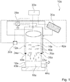
- FIG 1 shows a cleaning device 10a.
- the cleaning device 10 is intended for cleaning liquids, in particular contaminated water.
- Various applications of the cleaning device 10a which appear to be useful to a person skilled in the art are conceivable, such as for removing microorganisms 40a from drinking water, in particular for removing bacteria, protozoa, yeasts, viruses, fungi, fungal spores and / or algae.
- the cleaning device 10a has a first receiving area 12a for receiving a contaminated liquid 14a. Furthermore, the cleaning device 10a has a second receiving area 16a for receiving a cleaned liquid 18a.
- the first receiving area 12a and the second receiving area 16a are each arranged in a container 42a, 43a, which at least partially delimit the two receiving areas 12a, 16a.
- the containers 42a, 43a are exemplarily formed by a cylindrical, water-impermeable vessel. Basically, however, a separate design of the receiving areas 12a, 16a would also be conceivable.
- the containers 42a, 43a are congruent. Furthermore, the containers 42a, 43a are made of plastic.
- the first receiving area 12a and the second receiving area 16a are each formed by cylindrical areas which are delimited at least on one lateral surface by the respectively assigned container 42a, 43a.
- the Receiving areas 12a, 16a are arranged one above the other.
- the containers 42a, 43a are arranged one above the other.
- the container 43a has a removal means 44a in the area of the second receiving area 16a, by means of which the cleaned liquid 18a can be removed from the second receiving area 16a.
- the removal means 44a is formed, for example, by a water tap. In principle, however, it would also be conceivable for the removal means 44a to be formed, for example, by a valve, via which the cleaned liquid 18a is fed into a further container. Finally, the container 43a in particular has a stable base or base, which simplifies removal via the removal means 44a.
- the cleaning device 10a has a membrane unit 20a which is arranged between the first receiving area 12a and the second receiving area 16a and which partially serves as a separation medium between the first receiving area 12a and the second receiving area 16a.
- the membrane unit 20a comprises an electroosmotic membrane 22a.
- the electroosmotic membrane 22a serves as a separation medium between the two receiving areas 12a, 16a.
- the first receiving area 12a is delimited on an underside by the electroosmotic membrane 22a.
- the second receiving area 16a is arranged below the first receiving area 12a.
- the electroosmotic membrane 22a forms a base side of the first receiving area 12a, an outer surface of the first receiving area 12a being delimited by the container 42a.
- the electroosmotic membrane 22a forms a base side of the container 42a.
- the electroosmotic membrane 22a is connected to the container 42a via a seal 45a.
- the seal 45a is formed, for example, by an O-ring.
- the electroosmotic membrane 22a is arranged in the vertical direction between the first receiving area 12a and the second receiving area 16a.
- the electroosmotic membrane 22a has a first electrode 24a on a first surface. Furthermore, the electroosmotic membrane 22a has a second electrode 26a on a second surface opposite the first surface.
- the electroosmotic membrane 22a is provided to transport liquid from the first receiving area 12a into the second receiving area 16a by means of an electroosmotic effect.
- the cleaned liquid 18a in the second receiving area 16a in particular from the electroosmotic membrane 22a and is collected there.
- the pores 48a of the electroosmotic membrane 22a act both as a pump and as a separation medium.
- the first electrode 24a and the second electrode 26a are formed from a coating of an inert, conductive material, such as gold, on a base material of the electroosmotic membrane 22a.
- an inert, conductive material such as gold
- a base material of the electroosmotic membrane 22a Various basic materials for the electroosmotic membrane 22a which appear to be useful to a person skilled in the art are conceivable, such as, in particular, polydimethylsiloxane (PDMS), polycarbonate, polyester, Nafion or nylon.
- PDMS polydimethylsiloxane
- the electroosmotic membrane 22a has a thickness between 20 and 200 ⁇ m. Furthermore, the electroosmotic membrane 22a has a weight of approximately 25 g per m 2 .
- the electroosmotic membrane 22a can also be overlaid with tissue.
- tissue reinforcement of the electroosmotic membrane 22a in particular could be achieved.
- the tissues are in particular conductive and, so to speak, support the current distribution on the gold-vapor-coated surfaces of the electroosmotic membrane 22a ( Figures 2, 3 ).
- the electroosmotic membrane 22a has a pore size between 0.1 and 2 ⁇ m.
- a pore size of the electroosmotic membrane 22a is adapted to a liquid 14a to be cleaned.
- the electroosmotic effect of the electroosmotic membrane 22a depends on the pore size, with small pores in particular, in particular pores with a diameter of a few micrometers and being smaller, being more efficient than large ones. However, smaller pores offer greater flow resistance due to the viscosity of the liquid.
- both the pumping and the separating properties of the electroosmotic membrane can be defined.
- a wide variety of substances can preferably be separated by the electroosmotic membrane 22a.
- bacteria, protozoa i.e. in particular unicellular organisms such as cryptosporidia or amoebas, yeasts, fungi and their spores, pollen, worms of all kinds and their eggs, especially nematodes and their eggs
- bacteria, protozoa i.e. in particular unicellular organisms such as cryptosporidia or amoebas, yeasts, fungi and their spores, pollen, worms of all kinds and their eggs, especially nematodes and their eggs
- fibers, in particular organic and inorganic, particles of all types, in particular both organic and inorganic, and / or suspended matter of all types, in particular both organic and inorganic are separated off.
- the electroosmotic membrane 22a is designed to be exchangeable, in particular as a module.
- the cleaning device 10a has at least one voltage source 28a, 30a, which is provided in a first operating state to provide a voltage at the electrodes 24a, 26a of the membrane unit 20a.
- the cleaning device 10a has two voltage sources 28a, 30a, which are provided in a first operating state to provide a voltage at electrodes 24a, 26a of the membrane unit 20a.
- a first voltage source 28a is from a power supply with a protective ground.
- the first voltage source 28a is used to supply the membrane unit 20a with voltage when there is a power supply.
- a second voltage source 30a is formed by a solar system.
- the second voltage source 30a is formed by a photovoltaic system.
- the first voltage source 28a is used to supply the membrane unit 20a with voltage when there is sufficient sunlight and / or an autonomous operation of the cleaning device 10a is necessary.
- the cleaning device 10a also has a further voltage source 32a, which is formed by an energy store.
- the further voltage source 32a is formed by an accumulator.
- the further voltage source 32a is provided to provide a voltage at the electrodes 24a, 26a of the membrane unit 20a in at least a second operating state which is different from the first operating state.
- the further voltage source 32a serves to provide a voltage when no energy can be supplied by the first voltage source 28a or the second voltage source 30a.
- the additional voltage source 32a is used for self-sufficient operation of the cleaning device 10a to provide energy if the second voltage source 30a, that is to say the solar installation, does not provide or insufficient energy is provided.
- the further voltage source 32a serves in particular to implement night operation.
- the voltage sources 28a, 30a, 32a are each connected in parallel and in each case wired to the electrodes 24a, 26a of the membrane unit 20a, in particular using suitable cables. In principle, however, it would also be conceivable for the cleaning device 10a to have only one or two of the voltage sources 28a, 30a, 32a.
- the cleaning device 10a can in particular depending on an application with different voltage sources 28a, 30a, 32a.
- the voltage sources 28a, 30a, 32a each serve to provide a voltage of 1.0 to 10 volts.
- a minimum operating voltage of the membrane unit 20a is in particular approximately 1.2 volts.
- the membrane unit 20a has an exemplary transport capacity of up to 30 liters / m 2 per hour at 1.5 volts and up to 200 liters / m 2 per hour at 2.5 volts.
- a pressure of approximately 50 cm water column can be achieved by means of the membrane unit 20a.
- the cleaning device 10a has a control and regulating unit 33a, which is provided to control activation of the electroosmotic membrane 22a via the electrodes 24a, 26a.
- the control and regulating unit 33a is provided to specifically control the flow 46a of the liquid through the electroosmotic membrane 22a.
- the control includes both the direction of the flow 46a and its speed.
- the control and regulating unit 33a is preferably also coupled to an operating unit (not shown further) via which the cleaning device 10a can be controlled by an operator and / or specifications can be defined by an operator.
- the control and regulating unit 33a is coupled to control the cleaning device 10a with the voltage sources 28a, 30a, 32a.
- Figure 5 shows a schematic flow diagram of a method for operating the cleaning device 10a. The method is used to purify liquids, especially contaminated water.
- a voltage is applied to the electrodes 24a, 26a of the electroosmotic membrane 22a in a cleaning step 34a for cleaning a contaminated liquid 14a in the first receiving area 12a and liquid is transported from the first receiving area 12a into the second receiving area 16a by means of an electroosmotic effect ,
- the pore walls 50a of the pore 48a of the electroosmotic membrane 22a carry negative charges due to their material properties. Freely moving, dissociated positive charges from the liquid which fills the pore 48a are attached to these firmly bound negative charges.
- an electric field is now applied to the outer ends of the pore 48a by means of the electrodes 24a, 26a, so that the freely movable positive ones Charges migrate along the pore wall 50a to the negative pole, entraining all of the liquid in the pore 48a.
- the result is a liquid pump with no moving parts. What is special here is that the liquid movement thus created is uniform over the entire cross section of the pore.
- the pores 48a act simultaneously both as a pump and as a separation medium.
- the microorganisms 40a are separated from the liquid by the electroosmotic membrane 22a, the microorganisms 40a accumulating on the surface of the electroosmotic membrane 22a which is in contact with the contaminated liquid 14a ( Figure 4 ).
- the cleaning step 34a represents a basic operation.
- the cleaning device 10a can in particular be operated continuously in the cleaning step 34a, so that permanently contaminated water can be poured into the container 42a and purified water can be removed.
- the cleaned water can then be transferred to a clean tank so that water of drinking water quality can be removed permanently.
- a further cleaning step 36a of the method for cleaning the electroosmotic membrane 22a the voltage applied to the electrodes 24a is reversed. With a normal polarity of the electrodes 24a, 26a of the electroosmotic membrane 22a, as in particular during basic operation in the cleaning step 34a, liquid is transported from the first receiving area 12a into the second receiving area 16a.
- liquid if it is in contact with the electroosmotic membrane 22a, is temporarily transported from the second receiving area 16a to the first receiving area 12a by means of the electroosmotic membrane 22a, thereby causing impurities, in particular microorganisms 40a, which are on a surface of the first receiving area 12a have deposited electroosmotic membrane 22a, detached from the electroosmotic membrane 22a.
- the voltage applied to the electrodes 24a, 26a is therefore reversed temporarily, in particular for a defined period of time, to clean the electroosmotic membrane 22a.
- the detached microorganisms can then be used for an analysis, if this is provided. Alternatively, however, it would also be conceivable for the contaminated liquid 14a to be replaced or diluted in the first receiving region 12a, which now has increased contamination due to the cleaning step 34a.
- the microorganisms 40a detached from the electroosmotic membrane 22a in the cleaning step 36a are analyzed.
- Various methods for a microbiological analysis of the microorganisms which appear to be useful to a person skilled in the art are conceivable, such as, for example, polymerase chain reaction (PCR), enzyme-linked immunosorbent assay (ELISA) or cultivation on marker plates.
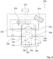
- FIG. 6 shows a cleaning device 10b.
- the cleaning device 10b is provided for cleaning liquids, in particular contaminated water.
- the cleaning device 10b has a first receiving area 12b for receiving a contaminated liquid 14b.
- the cleaning device 10b has a second receiving area 16b for receiving a cleaned liquid 18b.
- the first receiving area 12b and the second receiving area 16b are arranged in a common container 42b, which at least partially delimits the two receiving areas 12b, 16b.
- the container 42b is formed, for example, by a cylindrical, water-impermeable vessel.
- the first receiving area 12b is formed by a cylindrical area, the second receiving area 16b being formed by a hollow cylindrical area which surrounds the first receiving area 12b and delimits the container 42b on a lateral surface.
- the container 42b has a removal means 44b, via which the cleaned liquid 18b can be removed from the second receiving area 16b.
- the removal means 44b is formed, for example, by a tap.
- the cleaning has a membrane unit 20b which is arranged between the first receiving area 12b and the second receiving area 16b and which partially serves as a separation medium between the first receiving area 12b and the second receiving area 16b.
- the membrane unit 20b comprises an electroosmotic membrane 22b.
- the electroosmotic membrane 22b serves as a separation medium between the two receiving areas 12b, 16b.
- the electroosmotic membrane 22b at least substantially completely surrounds the first receiving region 12b in at least one plane.
- the electroosmotic membrane 22b is at least substantially completely surrounded by the second receiving region 16b in the at least one plane.
- the electroosmotic membrane 22b completely encloses the first receiving region 12b in the horizontal direction.
- the electroosmotic membrane 22b delimits a lateral surface of the first receiving area 12b. Furthermore, the second receiving area 16b extends in a ring around the first receiving area 12b, the receiving areas 12b, 16b being separated by the electroosmotic membrane 22b.
- the electroosmotic membrane 22b has a hollow cylindrical basic shape. In principle, however, a different shape of the receiving areas 12b, 16b and the electroosmotic membrane 22b that would appear to be useful to a person skilled in the art would also be conceivable. In the exemplary embodiment, however, it is essential that one of the receiving areas 12b, 16b is surrounded by the electroosmotic membrane 22b and the electroosmotic membrane 22a is in turn surrounded by the further receiving area 12b, 16b.
- electroosmotic membrane 22b It is also possible to use a plurality of hollow cylindrical electroosmotic membranes 22b in a container 42b. This multiplication could further increase the filter performance. Furthermore, with flexible stabilization, the electroosmotic membrane 22b could be formed into a tube. This would have the consequence that inserting the hose in the form of a screw into the container 42b would again increase the membrane surface and thus also the filter capacity. Furthermore, a slight atmospheric pressure of approx. 1 bar increases the filter speed.
- the electroosmotic membrane 22b is placed on a base side of the container 42b via a seal 45b.
- the seal 45b is exemplarily formed by an O-ring.
- the seal 45b firmly connects the stabilized electroosmotic membrane 22b to the bottom of the container 42b.
- the electroosmotic membrane 22b forms the first receiving area 12b in the container 42b.
- the electroosmotic membrane 22b has a first electrode 24b on a first surface. Furthermore, the electroosmotic membrane 22b has a second electrode 26b on a second surface opposite the first surface. When a voltage is applied, the electroosmotic membrane 22b is provided to transport liquid from the first receiving area 12b into the second receiving area 16b by means of an electroosmotic effect. The pores of the electroosmotic membrane 22b act both as a pump and as a separation medium.
Landscapes
- Engineering & Computer Science (AREA)
- Chemical & Material Sciences (AREA)
- Water Supply & Treatment (AREA)
- Chemical Kinetics & Catalysis (AREA)
- Health & Medical Sciences (AREA)
- Life Sciences & Earth Sciences (AREA)
- Urology & Nephrology (AREA)
- Analytical Chemistry (AREA)
- Hydrology & Water Resources (AREA)
- General Chemical & Material Sciences (AREA)
- Environmental & Geological Engineering (AREA)
- Electrochemistry (AREA)
- Organic Chemistry (AREA)
- Molecular Biology (AREA)
- Separation Using Semi-Permeable Membranes (AREA)
Abstract
Description
- Die Erfindung betrifft eine Reinigungsvorrichtung zur Reinigung von Flüssigkeiten.
- Aus der
US 2017/0095772 A1 ist bereits eine Reinigungsvorrichtung zur Reinigung von Flüssigkeiten bekannt, mit zumindest einem ersten Aufnahmebereich zu einer Aufnahme einer verunreinigten Flüssigkeit, mit zumindest einem zweiten Aufnahmebereich zu einer Aufnahme einer gereinigten Flüssigkeit und mit zumindest einer zwischen dem ersten Aufnahmebereich und dem zweiten Aufnahmebereich angeordneten Membraneinheit, welche zumindest teilweise als Trennmedium zwischen dem ersten Aufnahmebereich und dem zweiten Aufnahmebereich dient. - Ferner werden gegenwärtig Mikroorganismen aus Flüssigkeiten mittels Filtration entfernt. Dazu wird die entsprechende Flüssigkeit mittels einer Pumpe über spezielle Reinigungsfilter gepumpt. Gängige Filtrierungsmethoden sind beispielsweise Umkehrosmose oder das Reinigen mit einem Hohlfaserfilter. Nachteile der Reinigungsmethoden sind beispielsweise das starke Anheften der Bakterien auf dem Filter. Ein sanftes Ablösen ist nur schwer möglich. Auch wird bei diesen Reinigungsmethoden ein großer Anteil der Mikroorganismen geschädigt und abgetötet, so dass kein effektiver Nachweis von lebenden Keimen mehr möglich ist.
- Die Aufgabe der Erfindung besteht insbesondere darin, eine gattungsgemäße Vorrichtung mit verbesserten Eigenschaften hinsichtlich einer Variabilität und einer Kompaktheit bereitzustellen. Die Aufgabe wird erfindungsgemäß durch die Merkmale des Patentanspruchs 1 gelöst, während vorteilhafte Ausgestaltungen und Weiterbildungen der Erfindung den Unteransprüchen entnommen werden können.
- Die Erfindung geht aus von einer Reinigungsvorrichtung zur Reinigung von Flüssigkeiten, insbesondere von verunreinigtem Wasser, mit zumindest einem ersten Aufnahmebereich zu einer Aufnahme einer verunreinigten Flüssigkeit, mit zumindest einem zweiten Aufnahmebereich zu einer Aufnahme einer gereinigten Flüssigkeit und mit zumindest einer zwischen dem ersten Aufnahmebereich und dem zweiten Aufnahmebereich angeordneten Membraneinheit, welche zumindest teilweise als Trennmedium zwischen dem ersten Aufnahmebereich und dem zweiten Aufnahmebereich dient.
- Es wird vorgeschlagen, dass die zumindest eine Membraneinheit zumindest eine elektroosmotische Membran umfasst, die an einer ersten Oberfläche eine erste Elektrode aufweist und die bei einem Anlegen einer Spannung dazu vorgesehen ist, mittels eines elektroosmotischen Effekts Flüssigkeit von dem ersten Aufnahmebereich in den zweiten Aufnahmebereich zu transportieren. Vorzugsweise weist die zumindest eine Membraneinheit zumindest zwei Elektroden, und zwar eine erste Elektrode und eine zweite Elektrode, auf, wobei die elektroosmotische Membran zumindest die erste Elektrode aufweist. Bevorzugt sind die erste Elektrode und die zweite Elektrode zu einer Erzeugung eines elektrischen Felds vorgesehen. Vorzugsweise wirken die Poren der Membran sowohl als Pumpe als auch als Trennmedium. Insbesondere wirken die Poren der Membran bei einer anliegenden Spannung als Pumpe. Bevorzugt wirken die Poren der Membran als Trennmedium zwischen der Flüssigkeit des ersten Aufnahmebereichs und des zweiten Aufnahmebereichs, wobei durch Anlegen einer Spannung, insbesondere abhängig von einer Porengröße, die Flüssigkeit befreit von Schmutzpartikeln, Bakterien, Viren oder dergleichen durch die Membran gepumpt werden kann. Bevorzugt ist die erste Elektrode insbesondere von einer Beschichtung, insbesondere aus einem inerten, leitenden Material, wie beispielsweise Gold, auf einem Grundmaterial der elektroosmotischen Membran gebildet. Besonders bevorzugt ist die erste Elektrode an einer ersten Oberfläche der elektroosmotischen Membran angeordnet, welche sich parallel zu einer Haupterstreckungsebene der elektroosmotischen Membran erstreckt.
- Die Reinigungsvorrichtung ist insbesondere zur Reinigung verunreinigter Flüssigkeiten vorgesehen. Es sind verschiedene, einem Fachmann als sinnvoll erscheinende verunreinigte Flüssigkeiten zur Reinigung mittels der Reinigungsvorrichtung denkbar, wie insbesondere Wasser, insbesondere Trinkwasser, Schmutzwasser, wie beispielsweise Abwasser, Getränke, wie beispielsweise Säfte, Bier, Wein oder Sekt, Pufferlösungen, Saline, Säuren und Laugen, Blut, Urin, Speichel, Öle, Hydraulikflüssigkeiten, Kühlwasser und/oder Ballastwasser von Schiffen. Ferner kann die Reinigungsvorrichtung mit der elektroosmotischen Membran insbesondere in verschiedenen, einem Fachmann als sinnvoll erscheinenden Bereichen praktisch angewendet werden, wie beispielsweise zu der Entfernung von Mikroorganismen aus Trinkwasser, insbesondere zu der Entfernung von Bakterien, Protozoen, Hefen, Viren, Pilzen, Pilzsporen und/oder Algen, zu der Anreicherung von Mikroorganismen zum Zweck der Detektion und/oder Identifikation, zu der Abtrennung von nicht belebten Schwebstoffen anorganischer und organischer Art, wie insbesondere von Kunststoffen, Silikaten, Metallen, Holz, Erde, mineralische Verbindungen und/oder Ruß, zu der Reinigung von Getränken, wie insbesondere von Trinkwasser, Softdrinks, Säften, Milch und Milchprodukten und/oder von alkoholischen Getränken wie Bier, Wein und/oder Sekt, zur Proteinreinigung, zur Dialyse von Proteinen zur Umpufferung und Entsalzung bei der Proteinreinigung, zur Blutreinigung bei Niereninsuffizienz, wie insbesondere zu einem Einsatz als künstliche Niere oder künstliche Leber, zur Reinigung von Kühlwasser, zur Reinigung von Hydraulikflüssigkeit, im Brauereiwesen, insbesondere zur Abtrennung der Hefe nach dem Brauprozess, in der Weinherstellung, beispielsweise zur Klärung des Weins, zum Abernten eines Fermenters oder Bioreaktors für Bakterien, Algen oder Hefezellen, in Kläranlagen, insbesondere zur Aufarbeitung von Abwässern, und/oder in Lebenserhaltungssystemen in geschlossenen Habitaten, wie insbesondere in U-Booten, Raumstationen, Schiffen und/oder Polarstationen, insbesondere zur Aufarbeitung von Stoffwechselendprodukten wie Urin und Fäkalien. Ferner sind auch noch weitere Sonderanwendungen für die Reinigungsvorrichtung denkbar, wie beispielsweise für Wassertransporte jedweder Art, der Entfeuchtung von Luft und Gasen und/oder der Aufnahme von giftigen und radioaktiven Flüssigkeiten. Die Reinigungsvorrichtung kann daher insbesondere in verschiedenen Industriezweigen eingesetzt werden, wie beispielsweise in der Automobilindustrie, in der Flugzeugindustrie, in der Raumfahrt, in der pharmazeutischen Industrie, beim Militär, insbesondere für Auslandseinsätze, in der Forschung und in Analyselabors, bei Wasserwerken, in der Getränkeindustrie, bei Brauereien, bei Winzern und/oder Hilfsorganisation, wie beispielsweise "Rotes Kreuz", "Ärzte ohne Grenzen" oder dergleichen.
- Unter einem "Aufnahmebereich" soll in diesem Zusammenhang insbesondere ein Bereich verstanden werden, der zumindest zu einem Großteil materiell begrenzt ist und zu einer Aufnahme eines definierten Flüssigkeitsvolumens vorgesehen ist. Vorzugsweise ist der Aufnahmebereich zumindest teilweise durch einen den Aufnahmebereich begrenzenden Behälter gebildet. Ferner soll in diesem Zusammenhang unter einer "Membraneinheit" insbesondere eine Einheit verstanden werden, die zumindest ein Trennmedium, insbesondere eine Membran umfasst. Vorzugsweise umfasst die Membraneinheit eine als Trennschicht ausgebildete Membran. Besonders bevorzugt umfasst die Membraneinheit zumindest eine elektroosmotische Membran sowie Mittel zu einer Ansteuerung der elektroosmotischen Membran. Unter einer "elektroosmotischen Membran" soll in diesem Zusammenhang insbesondere eine Membran verstanden werden, welche bei einem Anlegen eines elektrischen Feldes, insbesondere senkrecht zu einer Oberfläche der Membran, zumindest eine Permeabilität, insbesondere eine selektive und/oder eine unidirektionale Permeabilität, aufweist. Vorzugsweise soll darunter insbesondere eine Membran verstanden werden, welche in zumindest einem Betriebszustand semipermeabel ausgebildet ist. Besonders bevorzugt soll darunter insbesondere eine Membran verstanden werden, bei welcher mittels Elektroosmose eine Permeabilität erzeugt werden kann. Vorzugsweise wandert bei der Membran eine Flüssigkeit mittels Elektroosmose durch die Poren der permeablen Membran mit Hilfe elektrischer Energie. Dabei tragen insbesondere die Wände einer Pore, welche insbesondere auch als Kapillare betrachtet werden kann, der Membran aufgrund ihrer Materialeigenschaften meist negative Ladungen, wie beispielsweise SiO- bei Quarz. An diese fest gebundenen negativen Ladungen lagern sich insbesondere frei bewegliche, dissoziierte positive Ladungen, insbesondere Protonen und/oder Ionen, aus der Flüssigkeit, welche die Pore oder Kapillare füllen, an. Es entsteht dabei insbesondere eine elektrochemische Doppelschicht. Wird nun an den äußeren Enden der Pore oder Kapillare ein elektrisches Feld angelegt, wandern insbesondere die frei beweglichen positiven Ladungen, insbesondere die Protonen und/oder Ionen, entlang der Poreninnenwand zum negativen Pol und reißen dabei die gesamte Flüssigkeit in der Pore oder Kapillare mit. Es ergibt sich dadurch insbesondere eine Flüssigkeitspumpe ohne bewegliche Teile. Bevorzugt ist die so entstehende Flüssigkeitsbewegung über den ganzen Querschnitt der Kapillare gleichförmig. Dies ist beispielsweise ein wichtiger Aspekt bei Verwendung des elektroosmotischen Effekts in der sogenannten Kapillarelektrophorese, also insbesondere einer chemisch-analytischen Methode. Besonders bevorzugt wirken die Poren bei der Membran somit gleichzeitig sowohl als Pumpe als auch als Trennmedium bzw. Filter.
- Vorzugsweise wird ein Fluss durch die elektroosmotische Membran gezielt gesteuert. Dies beinhaltet insbesondere sowohl die Richtung des Flusses als auch dessen Geschwindigkeit. Besonders bevorzugt erfolgt der Flüssigkeitstransport durch die elektroosmotische Membran durch einen elektrischen Potentialunterschied. Insbesondere kann für die Elektroosmose sowohl Wechsel- als auch Gleichspannung eingesetzt werden. Bevorzugt ist der elektroosmotische Fluss insbesondere abhängig von einer Oberflächenladung und damit abhängig von den Materialeigenschaften der elektroosmotischen Membran sowie vom pH-Wert der Flüssigkeit.
- Bevorzugt weist die elektroosmotische Membran eine geringe Dicke auf, insbesondere weniger als 200 µm. Hierdurch kann insbesondere erreicht werden, dass bereits eine geringe Spannung, wie insbesondere 1 bis 10 Volt, ausreicht, um eine hohe Feldstärke zu erzielen. Ferner können dadurch Richtung und Leistung des Flüssigkeitstransportes mit einer einfachen Elektronik gesteuert werden.
- Unter einer "Haupterstreckungsebene" einer Baueinheit soll insbesondere eine Ebene verstanden werden, welche parallel zu einer größten Seitenfläche eines kleinsten gedachten Quaders ist, welcher die Baueinheit gerade noch vollständig umschließt, und insbesondere durch den Mittelpunkt des Quaders verläuft. Unter "vorgesehen" soll insbesondere speziell programmiert, ausgelegt und/oder ausgestattet verstanden werden. Darunter, dass ein Objekt zu einer bestimmten Funktion vorgesehen ist, soll insbesondere verstanden werden, dass das Objekt diese bestimmte Funktion in zumindest einem Anwendungs- und/oder Betriebszustand erfüllt und/oder ausführt.
- Durch die erfindungsgemäße Ausgestaltung der Reinigungsvorrichtung kann insbesondere eine vorteilhaft effektive und energieeffiziente Vorrichtung zur Abtrennung von Verunreinigungen, insbesondere von Mikroorganismen aus Flüssigkeiten erreicht werden. Ferner können mittels der Reinigungsvorrichtung Flüssigkeiten effektiv ohne eine zusätzliche Pumpe von mikrobiologischen Verunreinigungen befreit werden. Des Weiteren kann dadurch ein zu hoher Druck an der Membran und damit die Gefahr von Durchbrüchen vermieden werden. Zudem kann dadurch ein effektives Anreichern von Mikroorganismen aus großen Flüssigkeitsvolumina ermöglicht werden. Ferner kann die Reinigungsvorrichtung insbesondere mit niedrigen Spannungen, wie insbesondere zwischen 1 und 10 Volt, betrieben werden, wodurch ein geringer Energieverbrauch möglich ist.
- Ferner wird vorgeschlagen, dass die zumindest eine elektroosmotische Membran an einer der ersten Oberfläche gegenüberliegenden zweiten Oberfläche eine zweite Elektrode aufweist. Vorzugsweise ist die zweite Elektrode insbesondere von einer Beschichtung, insbesondere aus einem inerten, leitenden Material, wie beispielsweise Gold, auf einem Grundmaterial der elektroosmotischen Membran gebildet. Besonders bevorzugt ist die zweite Elektrode an einer zweiten Oberfläche der elektroosmotischen Membran angeordnet, welche sich parallel zu einer Haupterstreckungsebene der elektroosmotischen Membran erstreckt. Vorzugsweise sind die erste Oberfläche und die zweite Oberfläche jeweils von sich parallel zueinander erstreckenden Hauptoberflächen der elektroosmotischen Membran gebildet. Bevorzugt weisen die erste Elektrode und die zweite Elektrode einen minimalen Abstand von maximal 200 µm, vorzugsweise von maximal 100 µm und besonders bevorzugt von maximal 50 µm auf. Dadurch kann insbesondere eine vorteilhaft effiziente Reinigungsvorrichtung bereitgestellt werden. Es kann insbesondere vorteilhaft ein elektroosmotischer Effekt bereitgestellt werden. Insbesondere durch den geringen Abstand der Elektroden kann die Reinigungsvorrichtung dadurch insbesondere mit niedrigen Spannungen, wie insbesondere zwischen 1 und 10 Volt, betrieben werden, wodurch ein geringer Energieverbrauch möglich ist.
- Des Weiteren wird vorgeschlagen, dass die Reinigungsvorrichtung zumindest eine Spannungsquelle aufweist, welche in zumindest einem ersten Betriebszustand dazu vorgesehen ist, eine Spannung an Elektroden der zumindest einen Membraneinheit bereitzustellen. Vorzugsweise ist die Spannungsquelle direkt, über eine Steuer- und/oder Regeleinheit oder über einen Schalter an die Elektroden der zumindest einen Membraneinheit angebunden. Es sind verschiedene, einem Fachmann als sinnvoll erscheinende Ausgestaltungen der Spannungsquelle denkbar, wie beispielsweise als ein Netzgerät, vorzugsweise ein Netzgerät mit einer Schutzerdung, als eine Batterie, als ein Akkumulator, als eine photovoltaische Solaranlage und/oder als ein Windrad mit Generator. Grundsätzlich wäre jedoch auch die Kombination mehrerer Spannungsquellen denkbar. Dadurch kann insbesondere eine vorteilhafte Energieversorgung der Membraneinheit bereitgestellt werden.
- Es wird ferner vorgeschlagen, dass die zumindest eine Spannungsquelle von einer Solaranlage gebildet ist. Vorzugsweise weist die Solaranlage zumindest eine Solarzelle, insbesondere zumindest ein Solarpanel, auf. Bevorzugt ist die Solaranlage von einer Photovoltaikanlage gebildet. Besonders bevorzugt ist die Solaranlage insbesondere zu einer direkten Umwandlung von Lichtenergie, insbesondere aus Sonnenlicht, in elektrische Energie mittels Solarzellen vorgesehen. Dadurch kann insbesondere ein vorteilhaft autarker Betrieb der Reinigungsvorrichtung ermöglicht werden. Es kann insbesondere ein Betrieb der Reinigungsvorrichtung unabhängig von herkömmlichen Stromquellen erreicht werden. Hierdurch ist die Reinigungsvorrichtung für den Einsatz in Gebieten, insbesondere in Krisengebieten, mit verminderter Infrastruktur sowie im Bereich der Raumfahrt, wie beispielsweise bei Explorationsthemen wie "Mission to Mars" oder "Colonization of the Moon", geeignet, wo herkömmliche Reinigungsverfahren nur schwer zu verwirklichen sind.
- Es wird weiter vorgeschlagen, dass die Reinigungsvorrichtung zumindest eine weitere Spannungsquelle aufweist, welche von einem Energiespeicher gebildet ist und dazu vorgesehen ist, in zumindest einem zweiten, von dem ersten Betriebszustand verschiedenen Betriebszustand eine Spannung an den Elektroden der zumindest einen Membraneinheit bereitzustellen. Es sind verschiedene, einem Fachmann als sinnvoll erscheinende Energiespeicher denkbar. Vorzugsweise ist der Energiespeicher von einer Batterie, insbesondere von einem Akkumulator gebildet. Bevorzugt dient die weitere Spannungsquelle zu einer Bereitstellung einer Spannung, wenn von der ersten Spannungsquelle keine Energie geliefert werden kann. Die weitere Spannungsquelle kann insbesondere zu einer Realisierung eines Nachtbetriebs verwendet werden. Die weitere Spannungsquelle dient insbesondere zu einer Energiebereitstellung, wenn von der ersten Spannungsquelle, insbesondere einer Solaranlage, keine oder nicht ausreichend Energie bereitgestellt wird. Hierdurch kann insbesondere eine vorteilhaft autarke Reinigungsvorrichtung bereitgestellt werden. Es kann insbesondere ein Betrieb der Reinigungsvorrichtung unabhängig von herkömmlichen Stromquellen erreicht werden. Hierdurch ist die Reinigungsvorrichtung für den Einsatz in Gebieten, insbesondere in Krisengebieten, mit verminderter Infrastruktur sowie im Bereich der Raumfahrt geeignet.
- Ferner wird vorgeschlagen, dass der erste Aufnahmebereich an einer Unterseite durch die elektroosmotische Membran begrenzt ist und der zweite Aufnahmebereich zumindest teilweise unterhalb des ersten Aufnahmebereichs angeordnet ist. Vorzugsweise bildet die elektroosmotische Membran eine Grundseite des ersten Aufnahmebereichs aus. Bevorzugt ist die elektroosmotische Membran in vertikaler Richtung zwischen dem ersten Aufnahmebereich und dem zweiten Aufnahmebereich angeordnet. Die Begriffe "Unterseite" und "vertikal" sind in diesem Zusammenhang insbesondere auf eine vorgesehene Betriebsstellung auf einem ebenen Untergrund bezogen, wobei der Untergrund eine Horizontale definiert und eine Aufstellfläche bildet. Bevorzugt ist die elektroosmotische Membran in einem gefüllten Zustand des ersten Aufnahmebereichs vollständig mit der verunreinigten Flüssigkeit benetzt, wobei die gereinigte Flüssigkeit in einem Pumpbetrieb der Membraneinheit von der elektroosmotischen Membran in den zweiten Aufnahmebereich abtropfen kann. Dadurch kann insbesondere eine vorteilhafte Anordnung der elektroosmotischen Membran bereitgestellt werden. Es kann insbesondere eine Anordnung erreicht werden, bei welcher die elektroosmotische Membran unabhängig von einem Füllstand des ersten Aufnahmebereichs vollständig mit Flüssigkeit benetzt ist. Dadurch kann insbesondere eine vorteilhaft effiziente Reinigungsvorrichtung bereitgestellt werden.
- Des Weiteren wird vorgeschlagen, dass die zumindest eine elektroosmotische Membran den ersten Aufnahmebereich in zumindest einer Ebene zumindest im Wesentlichen vollständig umschließt. Vorzugsweise ist die elektroosmotische Membran in der zumindest einen Ebene zumindest im Wesentlichen vollständig von dem zweiten Aufnahmebereich umgeben. Bevorzugt ist die Ebene von einer horizontalen Ebene gebildet. Besonders bevorzugt umschließt die zumindest eine elektroosmotische Membran den ersten Aufnahmebereich in horizontaler Richtung zumindest im Wesentlichen vollständig. Vorzugsweise erstreckt sich der zweite Aufnahmebereich ringförmig um den ersten Aufnahmebereich. Unter "zumindest im Wesentlichen vollständig umschließen" soll in diesem Zusammenhang insbesondere verstanden werden, dass ein Bauteil und/oder ein Bereich, insbesondere ausgehend von einem geometrischen Mittelpunkt des Bauteils und/oder des Bereichs, über einen Winkelbereich von zumindest 180°, vorzugsweise von zumindest 270° und besonders bevorzugt 360° von einem weiteren Bauteil und/oder Bereich umgeben, insbesondere begrenzt, ist. Dadurch kann insbesondere eine vorteilhafte Anordnung der elektroosmotischen Membran bereitgestellt werden. Es kann insbesondere eine vorteilhaft integrierte Anordnung des ersten Aufnahmebereichs erreicht werden. Hierdurch kann insbesondere eine vorteilhaft kompakte Reinigungsvorrichtung bei einer gleichzeitig vorteilhaft großen elektroosmotischen Membranoberfläche bereitgestellt werden. Insbesondere besteht durch die Steuerung des elektroosmotischen Effekts direkt an der elektroosmotischen Membran insbesondere eine weitgehende Freiheit in der Geometrie der Reinigungsvorrichtung, da die elektroosmotischen Membran in beliebiger Form angeordnet werden kann.
- Es wird ferner vorgeschlagen, dass die zumindest eine elektroosmotische Membran eine hohlzylindrische Grundform aufweist. Vorzugsweise ist der erste Aufnahmebereich zylindrisch ausgebildet, wobei die elektroosmotische Membran den ersten Aufnahmebereich hohlzylindrisch umschließt. Bevorzugt weist der zweite Aufnahmebereich ebenfalls eine hohlzylindrische Grundform auf und umschließt die elektroosmotische Membran. Dadurch kann insbesondere eine vorteilhaft raumeffiziente elektroosmotische Membran bereitgestellt werden. Hierdurch kann insbesondere eine vorteilhaft kompakte Reinigungsvorrichtung bei einer gleichzeitig vorteilhaft großen elektroosmotischen Membranoberfläche bereitgestellt werden. Hierdurch kann wiederum eine Erhöhung der Filtrationsrate erreicht werden. Insbesondere besteht durch die Steuerung des elektroosmotischen Effekts direkt an der elektroosmotischen Membran insbesondere eine weitgehende Freiheit in der Geometrie der Reinigungsvorrichtung, da die elektroosmotischen Membran in beliebiger Form angeordnet werden kann. Ferner kann dadurch insbesondere eine vorteilhaft stabile elektroosmotische Membran bereitgestellt werden. Es kann insbesondere eine selbsttragende elektroosmotische Membran bereitgestellt werden.
- Es wird weiter vorgeschlagen, dass die Reinigungsvorrichtung eine Steuer- und/oder Regeleinheit aufweist, welche dazu vorgesehen ist, eine Ansteuerung der elektroosmotischen Membran über Elektroden zu steuern und/oder zu regeln. Vorzugsweise ist die Steuer- und/oder Regeleinheit dazu vorgesehen, ein Anlegen einer Spannung an die Elektroden der Membraneinheit zu steuern. Bevorzugt ist die Steuer- und/oder Regeleinheit dazu vorgesehen, einen elektroosmotischen Effekt und damit eine Pumpwirkung der elektroosmotischen Membran zu steuern und/oder zu regeln. Unter einer "Steuer- und/oder Regeleinheit" soll insbesondere eine Einheit mit zumindest einer Steuerelektronik verstanden werden. Unter einer "Steuerelektronik" soll insbesondere eine Einheit mit einer Prozessoreinheit und mit einer Speichereinheit sowie mit einem in der Speichereinheit gespeicherten Betriebsprogramm verstanden werden. Dadurch kann insbesondere eine vorteilhaft gezielte Steuerung und/oder Regelung der Reinigungsvorrichtung erreicht werden.
- Ferner wird vorgeschlagen, dass eine Porengröße der elektroosmotischen Membran an eine zu reinigende Flüssigkeit angepasst ist. Vorzugsweise hängt der elektroosmotische Effekt von der Porengröße ab, wobei insbesondere kleine Poren, insbesondere Poren mit wenigen Mikrometern Durchmesser und geringer, effizienter sind als große. Kleinere Poren bieten jedoch insbesondere einen größeren Strömungswiderstand aufgrund der Viskosität der Flüssigkeit. Durch geeignete Wahl der Porengröße können insbesondere sowohl die Pump- als auch die Trenneigenschaften der elektroosmotischen Membran definiert werden. Bevorzugt können abhängig von der Porengröße die unterschiedlichsten Stoffe durch die elektroosmotische Membran abgetrennt werden. So können beispielsweise bei einer Porengröße von 0,1 bis 2 µm Bakterien, Protozoen, das heißt insbesondere Einzeller wie beispielswiese Cryptosporidien oder Amöben, Hefen, Pilze und deren Sporen, Pollen, Würmer aller Art und deren Eier, insbesondere Nematoden und deren Eier, kleine Arthropoden aller Art und deren Eier, Fasern, insbesondere organische und anorganische, Partikel aller Art, insbesondere sowohl organische als auch anorganische, und/oder Schwebstoffe aller Art, insbesondere sowohl organische als auch anorganische, abgetrennt werden. Bei einer Porengröße von weniger als 0,1 µm können dagegen beispielsweise Viren, Proteine, Antikörper, DNA, RNA, Partikel aller Art, insbesondere sowohl organische als auch anorganische, und/oder Schwebstoffe aller Art, insbesondere sowohl organische als auch anorganische, abgetrennt werden. Besonders bevorzugt wäre dabei insbesondere denkbar, dass die elektroosmotische Membran der Reinigungsvorrichtung austauschbar ausgebildet ist. Hierdurch kann insbesondere eine vielseitige Anwendung der Reinigungsvorrichtung erreicht werden. Es kann insbesondere ein vorteilhaft modularer Aufbau bereitgestellt werden. Vorzugsweise kann insbesondere abhängig von einer Anwendung eine Pumpleistung optimiert werden.
- Des Weiteren geht die Erfindung aus von einem Verfahren zu einem Betrieb der Reinigungsvorrichtung. Es wird vorgeschlagen, dass in einem Reinigungsschritt zu einer Reinigung einer verunreinigten Flüssigkeit in dem ersten Aufnahmebereich eine Spannung an Elektroden der elektroosmotischen Membran angelegt und mittels eines elektroosmotischen Effekts Flüssigkeit von dem ersten Aufnahmebereich in den zweiten Aufnahmebereich transportiert wird. Vorzugsweise wird in dem Reinigungsschritt mittels einer Spannungsquelle eine Spannung an gegenüberliegenden Elektroden der elektroosmotischen Membran angelegt. Dadurch kann insbesondere vorteilhaft eine effektive und energieeffiziente Abtrennung von Verunreinigungen, insbesondere von Mikroorganismen, aus Flüssigkeiten erreicht werden. Ferner können dadurch vorteilhaft Flüssigkeiten effektiv ohne eine zusätzliche Pumpe von mikrobiologischen Verunreinigungen befreit werden.
- Es wird ferner vorgeschlagen, dass in einem weiteren Reinigungsschritt zu einer Reinigung der elektroosmotischen Membran die an den Elektroden angelegte Spannung umgepolt und dadurch der elektroosmotische Transport umgekehrt wird. Vorzugsweise wird bei einer normalen Polung der Elektroden der elektroosmotischem Membran Flüssigkeit von dem ersten Aufnahmebereich in den zweiten Aufnahmebereich transportiert. Bevorzugt wird durch die Umpolung zumindest temporär Flüssigkeit mittels der elektroosmotischen Membran von dem zweiten Aufnahmebereich in den ersten Aufnahmebereich transportiert, wobei hierdurch insbesondere Verunreinigungen, welche sich auf einer dem ersten Aufnahmebereich zugewandten Oberfläche der elektroosmotischen Membran abgesetzt haben, von der elektroosmotischen Membran abgelöst werden. Bevorzugt wird in einem weiteren Reinigungsschritt zu einer Reinigung der elektroosmotischen Membran die an den Elektroden angelegte Spannung temporär, insbesondere für eine definierte Zeitdauer, umgepolt. Hierdurch kann insbesondere eine Reinigung der elektroosmotischem Membran erreicht werden. Es kann insbesondere durch eine einfache Umpolung des elektrischen Feldes an der elektroosmotischen Membran eine Reinigung der elektroosmotischen Membran ermöglicht werden. Ferner kann insbesondere ein sanftes Ablösen beispielsweise von Mikroorganismen von der elektroosmotischen Membran erreicht werden, sodass insbesondere die Mikroorganismen ihre Vitalität behalten. Dieser Aspekt kann beispielsweise für den Zweck einer Detektion und/oder Identifikation der Organismen genutzt werden.
- Es wird weiter vorgeschlagen, dass in einem auf den weiteren Reinigungsschritt folgenden Analyseschritt die in dem Reinigungsschritt von der elektroosmotischen Membran abgelösten Mikroorganismen, wie insbesondere Bakterien, mikrobiologisch analysiert werden. Vorzugsweise durch die Umpolung der angelegten Spannung wird der Fluss durch die elektroosmotischen Membran umgekehrt, sodass sich die Mikroorganismen, insbesondre Bakterien, effektiv von der elektroosmotischen Membran ablösen. Diese Eigenschaft wird dazu genutzt, dass die auf der Membran liegenden Mikroorganismen für eine mikrobiologische Analyse verwendet werden können. Durch diese Anreicherung werden die Mikroorganismen, insbesondere die Bakterien in ihrer Vitalität nicht beeinträchtigt. Vorzugsweise kann das Verfahren mit der Reinigungsvorrichtung insbesondere in einem kleinen Maßstab speziell für mikrobiologische Laboranalysen genutzt werden. Das effektive Ablösen der Bakterien durch einfache Umpolung erleichtert dabei eine Automatisierung der mikrobiologischen Analyse. Es sind verschiedene, einem Fachmann als sinnvoll erscheinende Methoden zur mikrobiologischen Analyse der Mikroorganismen denkbar, wie beispielsweise Polymerase-Kettenreaktion (PCR), Enzyme-Iinked Immunosorbent Assay (ELISA) oder die Kultivierung auf Markerplatten. Dadurch kann insbesondere eine vorteilhafte Untersuchung der abgelösten Mikroorganismen erreicht werden.
- Die erfindungsgemäße Reinigungsvorrichtung sowie das Verfahren sollen hierbei nicht auf die oben beschriebene Anwendung und Ausführungsform beschränkt sein. Insbesondere können die erfindungsgemäße Reinigungsvorrichtung sowie das Verfahren zu einer Erfüllung einer hierin beschriebenen Funktionsweise eine von einer hierin genannten Anzahl von einzelnen Elementen, Bauteilen und Einheiten sowie Verfahrensschritten abweichende Anzahl aufweisen. Zudem sollen bei den in dieser Offenbarung angegebenen Wertebereichen auch innerhalb der genannten Grenzen liegende Werte als offenbart und als beliebig einsetzbar gelten.
- Weitere Vorteile ergeben sich aus der folgenden Zeichnungsbeschreibung. In den Zeichnungen sind zwei Ausführungsbeispiele der Erfindung dargestellt. Die Zeichnungen, die Beschreibung und die Ansprüche enthalten zahlreiche Merkmale in Kombination. Der Fachmann wird die Merkmale zweckmäßigerweise auch einzeln betrachten und zu sinnvollen weiteren Kombinationen zusammenfassen.
- Es zeigen:
- Fig. 1
- Eine erfindungsgemäße Reinigungsvorrichtung mit einem ersten Aufnahmebereich, mit einem zweiten Aufnahmebereich, mit einer Membraneinheit, mit einer Spannungsquelle und mit einer weiteren Spannungsquelle in einer schematischen Darstellung,
- Fig. 2
- eine elektroosmotische Membran der Membraneinheit der erfindungsgemäßen Reinigungsvorrichtung in einer schematischen Darstellung,
- Fig. 3
- die Membraneinheit der erfindungsgemäßen Reinigungsvorrichtung mit der elektroosmotischen Membran, die eine erste Elektrode und eine zweite Elektrode umfasst, in einer schematischen Darstellung,
- Fig. 4
- eine schematische Funktionsdarstellung eines elektroosmotischen Flusses durch eine Pore in der elektroosmotischen Membran,
- Fig. 5
- ein schematisches Ablaufdiagramm eines Verfahrens zu einem Betrieb der erfindungsgemäßen Reinigungsvorrichtung und
- Fig. 6
- eine weitere erfindungsgemäße Reinigungsvorrichtung mit einem ersten Aufnahmebereich, mit einem zweiten Aufnahmebereich, mit einer Membraneinheit, mit einer Spannungsquelle und mit einer weiteren Spannungsquelle in einer schematischen Darstellung.
-
Figur 1 zeigt eine Reinigungsvorrichtung 10a. Die Reinigungsvorrichtung 10 ist zu einer Reinigung von Flüssigkeiten, insbesondere von verunreinigtem Wasser, vorgesehen. Es sind verschiedene, einem Fachmann als sinnvoll erscheinende Anwendungen der Reinigungsvorrichtung 10a denkbar, wie beispielsweise zu der Entfernung von Mikroorganismen 40a aus Trinkwasser, insbesondere zu der Entfernung von Bakterien, Protozoen, Hefen, Viren, Pilzen, Pilzsporen und/oder Algen. - Die Reinigungsvorrichtung 10a weist einen ersten Aufnahmebereich 12a zu einer Aufnahme einer verunreinigten Flüssigkeit 14a auf. Ferner weist die Reinigungsvorrichtung 10a einen zweiten Aufnahmebereich 16a zu einer Aufnahme einer gereinigten Flüssigkeit 18a auf. Der erste Aufnahmebereich 12a und der zweite Aufnahmebereich 16a sind jeweils in einem Behälter 42a, 43a angeordnet, welche die zwei Aufnahmebereiche 12a, 16a jeweils zumindest teilweise begrenzen. Die Behälter 42a, 43a sind beispielhaft von einem zylindrischen, wasserundurchlässigen Gefäß gebildet. Grundsätzlich wäre jedoch auch eine getrennte Ausbildung der Aufnahmebereiche 12a, 16a denkbar. Die Behälter 42a, 43a sind deckungsgleich ausgebildet. Ferner bestehen die Behälter 42a, 43a aus Kunststoff. Es wäre jedoch auch eine andere, einem Fachmann als sinnvoll erscheinende Materialgebung der Behälter 43a, 43a denkbar. Der erste Aufnahmebereich 12a und der zweite Aufnahmebereich 16a sind jeweils von zylindrischen Bereichen gebildet, welche zumindest an einer Mantelfläche durch den jeweils zugeordneten Behälter 42a, 43a begrenzt sind. Die Aufnahmebereiche 12a, 16a sind übereinander angeordnet. Grundsätzlich wäre jedoch auch eine andere, einem Fachmann als sinnvoll erscheinende Ausgestaltung denkbar. Die Behälter 42a, 43a sind übereinander angeordnet. Der Behälter 43a weist im Bereich des zweiten Aufnahmebereichs 16a ein Entnahmemittel 44a auf, über welches die gereinigte Flüssigkeit 18a aus dem zweiten Aufnahmebereich 16a entnommen werden kann. Das Entnahmemittel 44a ist beispielhaft von einem Wasserhahn gebildet. Grundsätzlich wäre jedoch auch denkbar, dass das Entnahmemittel 44a beispielsweise von einem Ventil gebildet ist, über welches die gereinigte Flüssigkeit 18a in einen weiteren Behälter geführt wird. Abschließend weist der Behälter 43a insbesondere einen stabilen Standfuß bzw. Sockel auf, der die Entnahme über das Entnahmemittel 44a vereinfacht.
- Des Weiteren weist die Reinigungsvorrichtung 10a eine zwischen dem ersten Aufnahmebereich 12a und dem zweiten Aufnahmebereich 16a angeordnete Membraneinheit 20a auf, welche teilweise als Trennmedium zwischen dem ersten Aufnahmebereich 12a und dem zweiten Aufnahmebereich 16a dient. Die Membraneinheit 20a umfasst eine elektroosmotische Membran 22a. Die elektroosmotische Membran 22a dient als Trennmedium zwischen den zwei Aufnahmebereichen 12a, 16a. Der erste Aufnahmebereich 12a ist an einer Unterseite durch die elektroosmotische Membran 22a begrenzt. Ferner ist der zweite Aufnahmebereich 16a unterhalb des ersten Aufnahmebereichs 12a angeordnet. Die elektroosmotische Membran 22a bildet eine Grundseite des ersten Aufnahmebereichs 12a aus, wobei eine Mantelfläche des ersten Aufnahmebereichs 12a durch den Behälter 42a begrenzt ist. Die elektroosmotische Membran 22a bildet eine Grundseite des Behälters 42a aus. Die elektroosmotische Membran 22a ist über eine Dichtung 45a an den Behälter 42a angebunden. Die Dichtung 45a ist beispielhaft von einem O-Ring gebildet. Die elektroosmotische Membran 22a ist in vertikaler Richtung zwischen dem ersten Aufnahmebereich 12a und dem zweiten Aufnahmebereich 16a angeordnet.
- Die elektroosmotische Membran 22a weist an einer ersten Oberfläche eine erste Elektrode 24a auf. Ferner weist die elektroosmotische Membran 22a an einer der ersten Oberfläche gegenüberliegenden zweiten Oberfläche eine zweite Elektrode 26a auf. Die elektroosmotische Membran 22a ist bei einem Anlegen einer Spannung dazu vorgesehen, mittels eines elektroosmotischen Effekts Flüssigkeit von dem ersten Aufnahmebereich 12a in den zweiten Aufnahmebereich 16a zu transportieren. Vorzugsweise tropft die gereinigte Flüssigkeit 18a in dem zweiten Aufnahmebereich 16a insbesondere von der elektroosmotischen Membran 22a ab und wird dort aufgefangen. Die Poren 48a der elektroosmotischen Membran 22a wirken sowohl als Pumpe, als auch als Trennmedium. Die erste Elektrode 24a und die zweite Elektrode 26a sind von einer Beschichtung aus einem inerten, leitenden Material, wie beispielsweise Gold, auf einem Grundmaterial der elektroosmotischen Membran 22a gebildet. Es sind verschiedene, einem Fachmann als sinnvoll erscheinende Grundmaterialien für die elektroosmotische Membran 22a denkbar, wie insbesondere Polydimethylsiloxan (PDMS), Polycarbonat, Polyester, Nafion oder Nylon. Die elektroosmotische Membran 22a weist eine Dicke zwischen 20 und 200 µm auf. Ferner weist die elektroosmotische Membran 22a ein Gewicht von ca. 25g pro m2 auf. Die elektroosmotische Membran 22a kann zudem überschichtet mit Gewebe ausgebildet sein. Hierdurch könnte insbesondere eine Gewebeverstärkung der elektroosmotischen Membran 22a erreicht werden. Die Gewebe sind dabei insbesondere leitfähig und unterstützen sozusagen die Stromverteilung auf den goldbedampften Oberflächen der elektroosmotischen Membran 22a (
Figuren 2, 3 ). - Des Weiteren weist die elektroosmotische Membran 22a eine Porengröße zwischen 0,1 und 2 µm auf. Eine Porengröße der elektroosmotischen Membran 22a ist an eine zu reinigende Flüssigkeit 14a angepasst. Der elektroosmotische Effekt der elektroosmotischen Membran 22a hängt von der Porengröße ab, wobei insbesondere kleine Poren, insbesondere Poren mit wenigen Mikrometern Durchmesser und geringer, effizienter sind als große. Kleinere Poren bieten jedoch einen größeren Strömungswiderstand aufgrund der Viskosität der Flüssigkeit. Durch geeignete Wahl der Porengröße können sowohl die Pump- als auch die Trenneigenschaften der elektroosmotischen Membran definiert werden. Bevorzugt können abhängig von der Porengröße die unterschiedlichsten Stoffe durch die elektroosmotische Membran 22a abgetrennt werden. Bei einer Porengröße von 0,1 bis 2 µm können Bakterien, Protozoen, das heißt insbesondere Einzeller wie beispielswiese Cryptosporidien oder Amöben, Hefen, Pilze und deren Sporen, Pollen, Würmer aller Art und deren Eier, insbesondere Nematoden und deren Eier, Kleine Arthropoden aller Art und deren Eier, Fasern, insbesondere organische und anorganische, Partikel aller Art, insbesondere sowohl organische als auch anorganische, und/oder Schwebstoffe aller Art, insbesondere sowohl organische als auch anorganische, abgetrennt werden. Bei einer Porengröße von weniger als 0,1 µm können dagegen beispielsweise Viren, Proteine, Antikörper, DNA, RNA, Partikel aller Art, insbesondere sowohl organische als auch anorganische, und/oder Schwebstoffe aller Art, insbesondere sowohl organische als auch anorganische, abgetrennt werden. Grundsätzlich wäre denkbar, dass die elektroosmotische Membran 22a austauschbar, wie insbesondere als Modul austauschbar, ausgebildet ist.
- Ferner weist die Reinigungsvorrichtung 10a zumindest eine Spannungsquelle 28a, 30a auf, welche in einem ersten Betriebszustand dazu vorgesehen ist, eine Spannung an den Elektroden 24a, 26a der Membraneinheit 20a bereitzustellen. Die Reinigungsvorrichtung 10a weist zwei Spannungsquellen 28a, 30a auf, welche in einem ersten Betriebszustand dazu vorgesehen sind, eine Spannung an Elektroden 24a, 26a der Membraneinheit 20a bereitzustellen. Eine erste Spannungsquelle 28a ist von einem Netzgerät mit einer Schutzerdung. Die erste Spannungsquelle 28a dient zu einer Spannungsversorgung der Membraneinheit 20a, wenn ein Stromnetz vorhanden ist. Eine zweite Spannungsquelle 30a ist von einer Solaranlage gebildet. Die zweite Spannungsquelle 30a ist von einer Photovoltaikanlage gebildet. Die erste Spannungsquelle 28a dient zu einer Spannungsversorgung der Membraneinheit 20a, wenn ausreichend Sonnenlicht vorhanden ist und/oder ein autarker Betrieb der Reinigungsvorrichtung 10a notwendig ist. Die Reinigungsvorrichtung 10a weist ferner eine weitere Spannungsquelle 32a auf, welche von einem Energiespeicher gebildet ist. Die weitere Spannungsquelle 32a ist von einem Akkumulator gebildet. Die weitere Spannungsquelle 32a ist dazu vorgesehen ist, in zumindest einem zweiten, von dem ersten Betriebszustand verschiedenen Betriebszustand eine Spannung an den Elektroden 24a, 26a der Membraneinheit 20a bereitzustellen. Die weitere Spannungsquelle 32a dient zu einer Bereitstellung einer Spannung, wenn von der ersten Spannungsquelle 28a oder der zweiten Spannungsquelle 30a keine Energie geliefert werden kann. Die weitere Spannungsquelle 32a dient bei einem autarken Betrieb der Reinigungsvorrichtung 10a zu einer Energiebereitstellung, wenn von der zweiten Spannungsquelle 30a, also der Solaranlage, keine oder nicht ausreichend Energie bereitgestellt wird. Die weitere Spannungsquelle 32a dient dabei insbesondere zu einer Realisierung eines Nachtbetriebs. Die Spannungsquellen 28a, 30a, 32a sind jeweils parallel geschaltet und jeweils mit den Elektroden 24a, 26a der Membraneinheit 20a verkabelt, insbesondere über geeignete Kabel. Grundsätzlich wäre jedoch auch denkbar, dass die Reinigungsvorrichtung 10a lediglich eine oder zwei der Spannungsquellen 28a, 30a, 32a aufweist. Die Reinigungsvorrichtung 10a kann insbesondere abhängig von einer Anwendung mit verschiedenen Spannungsquellen 28a, 30a, 32a ausgestattet werden.
- Die Spannungsquellen 28a, 30a, 32a dienen jeweils zu einer Bereitstellung von einer Spannung von 1,0 bis 10 Volt. Eine minimale Betriebsspannung der Membraneinheit 20a beträgt insbesondere ca. 1,2 Volt. Ferner weist die Membraneinheit 20a beispielhaft eine Transportleistung von bis zu 30 Liter/m2 in der Stunde bei 1,5 Volt und von bis zu 200 Liter/m2 in der Stunde bei 2,5 Volt auf. Zudem ist mittels der Membraneinheit 20a ein Druck von ca. 50 cm Wassersäule erreichbar.
- Des Weiteren weist die Reinigungsvorrichtung 10a eine Steuer- und Regeleinheit 33a auf, welche dazu vorgesehen ist, eine Ansteuerung der elektroosmotischen Membran 22a über die Elektroden 24a, 26a zu steuern. Die Steuer- und Regeleinheit 33a ist dazu vorgesehen, den Fluss 46a der Flüssigkeit durch die elektroosmotische Membran 22a gezielt zu steuern. Die Steuerung beinhaltet dabei insbesondere sowohl die Richtung des Flusses 46a als auch dessen Geschwindigkeit. Vorzugsweise ist die Steuer- und Regeleinheit 33a zudem mit einer nicht weiter dargestellten Bedieneinheit gekoppelt, über welche die Reinigungsvorrichtung 10a von einem Bediener gesteuert werden kann und/oder von einem Bediener Vorgaben festgelegt werden können. Die Steuer- und Regeleinheit 33a ist zu einer Steuerung der Reinigungsvorrichtung 10a mit den Spannungsquellen 28a, 30a, 32a gekoppelt.
-
Figur 5 zeigt ein schematisches Ablaufdiagramm eines Verfahrens zu einem Betrieb der Reinigungsvorrichtung 10a. Das Verfahren dient zu einer Reinigung von Flüssigkeiten, insbesondere von verunreinigtem Wasser. - Bei dem Verfahren wird in einem Reinigungsschritt 34a zu einer Reinigung einer verunreinigten Flüssigkeit 14a in dem ersten Aufnahmebereich 12a eine Spannung an die Elektroden 24a, 26a der elektroosmotischen Membran 22a angelegt und mittels eines elektroosmotischen Effekts Flüssigkeit von dem ersten Aufnahmebereich 12a in den zweiten Aufnahmebereich 16a transportiert. Die Porenwände 50a der Pore 48a der elektroosmotischen Membran 22a tragen aufgrund ihrer Materialeigenschaften negative Ladungen. An diese fest gebundenen negativen Ladungen lagern sich frei bewegliche, dissoziierte positive Ladungen aus der Flüssigkeit, welche die Pore 48a füllt, an. In dem Reinigungsschritt 34a wird nun an den äußeren Enden der Pore 48a mittels der Elektroden 24a, 26a ein elektrisches Feld angelegt, sodass die frei beweglichen positiven Ladungen entlang der Porenwand 50a zum negativen Pol wandern und dabei die gesamte Flüssigkeit in der Pore 48a mitreißen. Es ergibt sich dadurch eine Flüssigkeitspumpe ohne bewegliche Teile. Besonders ist dabei, dass die so entstehende Flüssigkeitsbewegung über den ganzen Querschnitt der Pore gleichförmig ist. Bei der elektroosmotischen Membran 22a wirken die Poren 48a gleichzeitig sowohl als Pumpe als auch als Trennmedium. Hierbei werden die Mikroorganismen 40a durch die elektroosmotische Membran 22a von der Flüssigkeit separiert, wobei sich die Mikroorganismen 40a auf der Oberfläche der elektroosmotischen Membran 22a, die Kontakt mit der verschmutzten Flüssigkeit 14a hat, anreichern (
Figur 4 ). - Der Reinigungsschritt 34a stellt einen Grundbetrieb dar. Die Reinigungsvorrichtung 10a kann dabei insbesondere kontinuierlich in dem Reinigungsschritt 34a betrieben werden, so dass permanent verschmutztes Wasser in den Behälter 42a eingefüllt und gereinigtes Wasser entnommen werden kann. Das gereinigte Wasser kann dann in einen sauberen Tank überführt werden, so dass permanent Wasser in Trinkwasserqualität entnommen werden kann.
- In einem weiteren Reinigungsschritt 36a des Verfahrens zu einer Reinigung der elektroosmotischen Membran 22a wird die an den Elektroden 24a angelegte Spannung umgepolt. Bei einer normalen Polung der Elektroden 24a, 26a der elektroosmotischem Membran 22a, wie insbesondere bei einem Grundbetrieb bei dem Reinigungsschritt 34a, wird Flüssigkeit von dem ersten Aufnahmebereich 12a in den zweiten Aufnahmebereich 16a transportiert. Durch die Umpolung wird temporär Flüssigkeit, sofern an der elektroosmotischen Membran 22a anliegend, mittels der elektroosmotischen Membran 22a von dem zweiten Aufnahmebereich 16a in den ersten Aufnahmebereich 12a transportiert, wobei hierdurch Verunreinigungen, insbesondere Mikroorganismen 40a welche sich auf einer dem ersten Aufnahmebereich 12a zugewandten Oberfläche der elektroosmotischen Membran 22a abgesetzt haben, von der elektroosmotischen Membran 22a abgelöst werden. In dem weiteren Reinigungsschritt 36a wird zu einer Reinigung der elektroosmotischen Membran 22a daher die an den Elektroden 24a, 26a angelegte Spannung temporär, insbesondere für eine definierte Zeitdauer, umgepolt.
- Anschließend können die abgelösten Mikroorganismen zu einer Analyse genutzt werden, falls dies vorgesehen ist. Alternativ wäre jedoch auch denkbar, dass die verunreinigte Flüssigkeit 14a in dem ersten Aufnahmebereich 12a, welche durch den Reinigungsschritt 34a nun eine erhöhte Verunreinigung aufweist, ersetzt oder verdünnt wird. Zu einer Analyse wird in einem auf den weiteren Reinigungsschritt 36a folgenden Analyseschritt 38a die in dem Reinigungsschritt 36a von der elektroosmotischen Membran 22a abgelösten Mikroorganismen 40a mikrobiologisch analysiert. Es sind verschiedene, einem Fachmann als sinnvoll erscheinende Methoden zur mikrobiologischen Analyse der Mikroorganismen denkbar, wie beispielsweise Polymerase-Kettenreaktion (PCR), Enzyme-Iinked Immunosorbent Assay (ELISA) oder die Kultivierung auf Markerplatten.
- In der
Figur 6 ist ein weiteres Ausführungsbeispiel der Erfindung gezeigt. Die nachfolgenden Beschreibungen beschränken sich im Wesentlichen auf die Unterschiede zwischen den Ausführungsbeispielen, wobei bezüglich gleich bleibender Bauteile, Merkmale und Funktionen auf die Beschreibung des Ausführungsbeispiels derFiguren 1 bis 5 verwiesen werden kann. Zur Unterscheidung der Ausführungsbeispiele ist der Buchstabe a in den Bezugszeichen des Ausführungsbeispiels in denFiguren 1 bis 5 durch den Buchstaben b in den Bezugszeichen des Ausführungsbeispiels derFigur 6 ersetzt. Bezüglich gleich bezeichneter Bauteile, insbesondere in Bezug auf Bauteile mit gleichen Bezugszeichen, kann grundsätzlich auch auf die Zeichnungen und/oder die Beschreibung des Ausführungsbeispiels derFiguren 1 bis 5 verwiesen werden. -
Figur 6 zeigt eine Reinigungsvorrichtung 10b. Die Reinigungsvorrichtung 10b ist zu einer Reinigung von Flüssigkeiten, insbesondere von verunreinigtem Wasser, vorgesehen. Die Reinigungsvorrichtung 10b weist einen ersten Aufnahmebereich 12b zu einer Aufnahme einer verunreinigten Flüssigkeit 14b auf. Ferner weist die Reinigungsvorrichtung 10b einen zweiten Aufnahmebereich 16b zu einer Aufnahme einer gereinigten Flüssigkeit 18b. Der erste Aufnahmebereich 12b und der zweite Aufnahmebereich 16b sind in einem gemeinsamen Behälter 42b angeordnet, welche die zwei Aufnahmebereiche 12b, 16b zumindest teilweise begrenzt. Der Behälter 42b ist beispielhaft von einem zylindrischen, wasserundurchlässigen Gefäß gebildet. Der erste Aufnahmebereich 12b ist von einem zylindrischen Bereich gebildet, wobei der zweite Aufnahmebereich 16b von einem den ersten Aufnahmebereich 12b umschließenden hohlzylindrischen Bereich gebildet ist, welcher an einer Mantelfläche den Behälter 42b begrenzt. Der Behälter 42b weist ein Entnahmemittel 44b auf, über welches die gereinigte Flüssigkeit 18b aus dem zweiten Aufnahmebereich 16b entnommen werden kann. Das Entnahmemittel 44b ist beispielhaft von einem Hahn gebildet. - Des Weiteren weist die Reinigung eine zwischen dem ersten Aufnahmebereich 12b und dem zweiten Aufnahmebereich 16b angeordnete Membraneinheit 20b auf, welche teilweise als Trennmedium zwischen dem ersten Aufnahmebereich 12b und dem zweiten Aufnahmebereich 16b dient. Die Membraneinheit 20b umfasst eine elektroosmotische Membran 22b. Die elektroosmotische Membran 22b dient als Trennmedium zwischen den zwei Aufnahmebereichen 12b, 16b. Die elektroosmotische Membran 22b umschließt den ersten Aufnahmebereich 12b in zumindest einer Ebene zumindest im Wesentlichen vollständig. Ferner ist die elektroosmotische Membran 22b in der zumindest einen Ebene zumindest im Wesentlichen vollständig von dem zweiten Aufnahmebereich 16b umgeben. Die elektroosmotische Membran 22b umschließt den ersten Aufnahmebereich 12b in horizontaler Richtung vollständig. Die elektroosmotische Membran 22b begrenzt eine Mantelfläche des ersten Aufnahmebereichs 12b. Ferner erstreckt sich der zweite Aufnahmebereich 16b ringförmig um den ersten Aufnahmebereich 12b, wobei die Aufnahmebereiche 12b, 16b durch die elektroosmotische Membran 22b getrennt sind. Die elektroosmotische Membran 22b weist eine hohlzylindrische Grundform auf. Grundsätzlich wäre jedoch auch eine andere, einem Fachmann als sinnvoll erscheinende Formgebung der Aufnahmebereich 12b, 16b und der elektroosmotischen Membran 22b denkbar. Insbesondere ist bei dem Ausführungsbeispiel jedoch wesentlich, dass einer der Aufnahmebereiche 12b, 16b von der elektroosmotischen Membran 22b umgeben ist und die elektroosmotische Membran 22a wiederum von dem weiteren Aufnahmebereich 12b, 16b umgeben ist.
- Eine Verwendung mehrerer hohlzylindrischer elektroosmotischer Membranen 22b in einem Behälter 42b ist ebenfalls möglich. Diese Vervielfachung könnte nochmals die Filterleistung erhöhen. Weiterhin könnte bei einer flexiblen Stabilisierung die elektroosmotische Membran 22b zu einem Schlauch geformt werden. Dies hätte zur Folge, dass ein Einlegen des Schlauchs in Form einer Schnecke in den Behälter 42b nochmals die Membranoberfläche und somit auch die Filterkapazität erhöhen würde. Des Weiteren erhöht ein leichter atmosphärischer Druck von ca. 1 bar die Filtergeschwindigkeit.
- Die elektroosmotischen Membran 22b ist über eine Dichtung 45b auf eine Grundseite des Behälters 42b aufgesetzt. Die Dichtung 45b ist beispielhaft von einem O-Ring gebildet. Die Dichtung 45b verbindet die stabilisierte elektroosmotischen Membran 22b fest mit dem Boden des Behälters 42b. Die elektroosmotische Membran 22b bildet den ersten Aufnahmebereich 12b in dem Behälter 42b aus.
- Die elektroosmotische Membran 22b weist an einer ersten Oberfläche eine erste Elektrode 24b auf. Ferner weist die elektroosmotische Membran 22b an einer der ersten Oberfläche gegenüberliegenden zweiten Oberfläche eine zweite Elektrode 26b auf. Die elektroosmotische Membran 22b ist bei einem Anlegen einer Spannung dazu vorgesehen, mittels eines elektroosmotischen Effekts Flüssigkeit von dem ersten Aufnahmebereich 12b in den zweiten Aufnahmebereich 16b zu transportieren. Die Poren der elektroosmotischen Membran 22b wirken sowohl als Pumpe, als auch als Trennmedium.
-
- 10
- Reinigungsvorrichtung
- 12
- Aufnahmebereich
- 14
- Flüssigkeit
- 16
- Aufnahmebereich
- 18
- Flüssigkeit
- 20
- Membraneinheit
- 22
- Membran
- 24
- Elektrode
- 26
- Elektrode
- 28
- Spannungsquelle
- 30
- Spannungsquelle
- 32
- Spannungsquelle
- 33
- Steuer- und Regeleinheit
- 34
- Reinigungsschritt
- 36
- Reinigungsschritt
- 38
- Analyseschritt
- 40
- Mikroorganismen
- 42
- Behälter
- 43
- Behälter
- 44
- Entnahmemittel
- 45
- Dichtung
- 46
- Fluss
- 48
- Pore
- 50
- Porenwand
Claims (14)
- Reinigungsvorrichtung zur Reinigung von Flüssigkeiten, insbesondere von verunreinigtem Wasser, mit zumindest einem ersten Aufnahmebereich (12a; 12b) zu einer Aufnahme einer verunreinigten Flüssigkeit (14a; 14b), mit zumindest einem zweiten Aufnahmebereich (16a; 16b) zu einer Aufnahme einer gereinigten Flüssigkeit (18a; 18b) und mit zumindest einer zwischen dem ersten Aufnahmebereich (12a; 12b) und dem zweiten Aufnahmebereich (16a; 16b) angeordneten Membraneinheit (20a; 20b), welche zumindest teilweise als Trennmedium zwischen dem ersten Aufnahmebereich (12a; 12b) und dem zweiten Aufnahmebereich (16a; 16b) dient,
dadurch gekennzeichnet, dass
die zumindest eine Membraneinheit (20a; 20b) zumindest eine elektroosmotische Membran (22a; 22b) umfasst, die an einer ersten Oberfläche eine erste Elektrode (24a) aufweist und die bei einem Anlegen einer Spannung dazu vorgesehen ist, mittels eines elektroosmotischen Effekts Flüssigkeit von dem ersten Aufnahmebereich (12a; 12b) in den zweiten Aufnahmebereich (16a; 16b) zu transportieren. - Reinigungsvorrichtung nach Anspruch 1,
dadurch gekennzeichnet, dass
die zumindest eine elektroosmotische Membran (22a; 22b) an einer der ersten Oberfläche gegenüberliegenden zweiten Oberfläche eine zweite Elektrode (26a) aufweist. - Reinigungsvorrichtung nach Anspruch 1 oder 2,
gekennzeichnet durch
zumindest eine Spannungsquelle (28a, 30a; 28b, 30b), welche in zumindest einem ersten Betriebszustand dazu vorgesehen ist, eine Spannung an Elektroden (24a, 26a) der zumindest einen Membraneinheit (20a; 20b) bereitzustellen. - Reinigungsvorrichtung nach Anspruch 3,
dadurch gekennzeichnet, dass
die zumindest eine Spannungsquelle (30a; 30b) von einer Solaranlage gebildet ist. - Reinigungsvorrichtung nach Anspruch 3 oder 4,
gekennzeichnet durch
zumindest eine weitere Spannungsquelle (32a; 32b), welche von einem Energiespeicher gebildet ist und dazu vorgesehen ist, in zumindest einem zweiten, von dem ersten Betriebszustand verschiedenen Betriebszustand eine Spannung an Elektroden (24a, 26a) der zumindest einen Membraneinheit (20a; 20b) bereitzustellen. - Reinigungsvorrichtung nach einem der vorhergehenden Ansprüche,
dadurch gekennzeichnet, dass
der erste Aufnahmebereich (12a) an einer Unterseite durch die elektroosmotische Membran (22a) begrenzt ist und der zweite Aufnahmebereich (16a) zumindest teilweise unterhalb des ersten Aufnahmebereichs (12a) angeordnet ist. - Reinigungsvorrichtung zumindest nach einem der Ansprüche 1 bis 5,
dadurch gekennzeichnet, dass
die zumindest eine elektroosmotische Membran (22b) den ersten Aufnahmebereich (12b) in zumindest einer Ebene zumindest im Wesentlichen vollständig umschließt. - Reinigungsvorrichtung nach Anspruch 7,
dadurch gekennzeichnet, dass
die zumindest eine elektroosmotische Membran (22b) eine hohlzylindrische Grundform aufweist. - Reinigungsvorrichtung nach einem der vorhergehenden Ansprüche,
gekennzeichnet durch
eine Steuer- und/oder Regeleinheit (33a; 33b), welche dazu vorgesehen ist, eine Ansteuerung der elektroosmotischen Membran (22a; 22b) über Elektroden (24a, 26a; 24b, 26b) zu steuern und/oder zu regeln. - Reinigungsvorrichtung nach einem der vorhergehenden Ansprüche,
dadurch gekennzeichnet, dass
eine Porengröße der elektroosmotischen Membran (22a; 22b) an eine zu reinigende Flüssigkeit (14a; 14b) angepasst ist. - Verfahren zu einem Betrieb der Reinigungsvorrichtung (10a; 10b) nach einem der vorhergehenden Ansprüche.
- Verfahren nach Anspruch 11,
dadurch gekennzeichnet, dass
in einem Reinigungsschritt (34a) zu einer Reinigung einer verunreinigten Flüssigkeit (14a; 14b) in dem ersten Aufnahmebereich (12a; 12b) eine Spannung an Elektroden (24a, 26a) der elektroosmotischen Membran (22a; 22b) angelegt und mittels eines elektroosmotischen Effekts Flüssigkeit von dem ersten Aufnahmebereich (12a; 12b) in den zweiten Aufnahmebereich (16a; 16b) transportiert wird. - Verfahren nach Anspruch 11 oder 12,
dadurch gekennzeichnet, dass
in einem weiteren Reinigungsschritt (36a) zu einer Reinigung der elektroosmotischen Membran (22a; 22b) die an den Elektroden (24a, 26a) angelegte Spannung umgepolt wird. - Verfahren nach Anspruch 13,
dadurch gekennzeichnet, dass
in einem auf den weiteren Reinigungsschritt (36a) folgenden Analyseschritt (38a) die in dem Reinigungsschritt (36a) von der elektroosmotischen Membran (22a; 22b) abgelösten Mikroorganismen (40a; 40b) mikrobiologisch analysiert werden.
Priority Applications (1)
| Application Number | Priority Date | Filing Date | Title |
|---|---|---|---|
| EP18183339.3A EP3594187B1 (de) | 2018-07-13 | 2018-07-13 | Verwendung einer reinigungsvorrichtung zur wasserreinigung |
Applications Claiming Priority (1)
| Application Number | Priority Date | Filing Date | Title |
|---|---|---|---|
| EP18183339.3A EP3594187B1 (de) | 2018-07-13 | 2018-07-13 | Verwendung einer reinigungsvorrichtung zur wasserreinigung |
Publications (2)
| Publication Number | Publication Date |
|---|---|
| EP3594187A1 true EP3594187A1 (de) | 2020-01-15 |
| EP3594187B1 EP3594187B1 (de) | 2022-06-08 |
Family
ID=63079721
Family Applications (1)
| Application Number | Title | Priority Date | Filing Date |
|---|---|---|---|
| EP18183339.3A Active EP3594187B1 (de) | 2018-07-13 | 2018-07-13 | Verwendung einer reinigungsvorrichtung zur wasserreinigung |
Country Status (1)
| Country | Link |
|---|---|
| EP (1) | EP3594187B1 (de) |
Cited By (1)
| Publication number | Priority date | Publication date | Assignee | Title |
|---|---|---|---|---|
| EP4344993A1 (de) | 2022-09-29 | 2024-04-03 | Airbus Operations GmbH | Wärme- und schalldämmungssystem für ein flugzeug |
Citations (5)
| Publication number | Priority date | Publication date | Assignee | Title |
|---|---|---|---|---|
| US3725233A (en) * | 1969-06-05 | 1973-04-03 | American Bioculture | Electro-osmosis system |
| US4118299A (en) * | 1977-07-14 | 1978-10-03 | Henri Jean Robert Maget | Electrochemical water desalination process |
| US20110097215A1 (en) * | 2009-10-23 | 2011-04-28 | The Government Of The United States Of America, As Represented By The Secretary Of The Navy | Flexible Solid-State Pump Constructed of Surface-Modified Glass Fiber Filters and Metal Mesh Electrodes |
| US20170088443A1 (en) * | 2015-09-30 | 2017-03-30 | United States Of America As Represented By The Secretary Of The Army | Electrokinetic purification device |
| US20170095772A1 (en) | 2015-10-02 | 2017-04-06 | Lawrence Livermore National Security, Llc | Filtration device for rapid separation of biological particles from complex matrices |
-
2018
- 2018-07-13 EP EP18183339.3A patent/EP3594187B1/de active Active
Patent Citations (5)
| Publication number | Priority date | Publication date | Assignee | Title |
|---|---|---|---|---|
| US3725233A (en) * | 1969-06-05 | 1973-04-03 | American Bioculture | Electro-osmosis system |
| US4118299A (en) * | 1977-07-14 | 1978-10-03 | Henri Jean Robert Maget | Electrochemical water desalination process |
| US20110097215A1 (en) * | 2009-10-23 | 2011-04-28 | The Government Of The United States Of America, As Represented By The Secretary Of The Navy | Flexible Solid-State Pump Constructed of Surface-Modified Glass Fiber Filters and Metal Mesh Electrodes |
| US20170088443A1 (en) * | 2015-09-30 | 2017-03-30 | United States Of America As Represented By The Secretary Of The Army | Electrokinetic purification device |
| US20170095772A1 (en) | 2015-10-02 | 2017-04-06 | Lawrence Livermore National Security, Llc | Filtration device for rapid separation of biological particles from complex matrices |
Cited By (2)
| Publication number | Priority date | Publication date | Assignee | Title |
|---|---|---|---|---|
| EP4344993A1 (de) | 2022-09-29 | 2024-04-03 | Airbus Operations GmbH | Wärme- und schalldämmungssystem für ein flugzeug |
| US12539956B2 (en) | 2022-09-29 | 2026-02-03 | Airbus Operations Gmbh | Thermal and acoustic insulation system for an aircraft |
Also Published As
| Publication number | Publication date |
|---|---|
| EP3594187B1 (de) | 2022-06-08 |
Similar Documents
| Publication | Publication Date | Title |
|---|---|---|
| Shivajirao | Treatment of distillery wastewater using membrane technologies | |
| DE60308189T2 (de) | Abwasserbehandlung mittels fest-flüssigtrennung und gepulste elektrische felder | |
| EP1147803B1 (de) | Vorrichtung zum Filtern und Trennen von insbesondere biologisch organischen Strömungsmedien | |
| EP1268044A1 (de) | Crossflow-filtrationseinheit | |
| CN205603403U (zh) | 一种含氮杂环化合物化工尾水的深度处理装置及其电化学氧化单元 | |
| CN109384307A (zh) | 一种以电化学强化碳纳米管中空纤维膜为分离单元的膜生物反应器 | |
| EP3594187B1 (de) | Verwendung einer reinigungsvorrichtung zur wasserreinigung | |
| AU2007206356A1 (en) | Membrane filtration apparatus and its operating method | |
| EP1277831B1 (de) | Verfahren und Vorrichtung zur Ernte mikrobieller Biomasse aus einem Kultivationssystem | |
| CN207685046U (zh) | 具有管式膜过滤装置的废水处理设备 | |
| EP1280885B1 (de) | Verfahren zur abtrennung von lebensfähigen säuger- oder insekten-zellen aus zellsuspensionen | |
| CN103706255B (zh) | 用于膜生物反应器的模块化平板式滤膜元件 | |
| CN106115983A (zh) | 基于膜技术的染料废水处理装置 | |
| DE202021102883U1 (de) | Meerwasserentsalzung bzw. Deionisierung von Wasser im industriellen Maßstab unter Verwendung von Rohrleitungssystemen durch Elektrizität und / oder magnetischen Feldern | |
| CN112755634A (zh) | 一种蒸馏水过滤设备及过滤方法 | |
| EP3746213B1 (de) | Vorrichtung und verfahren zum erzeugen von gasblasen in einer flüssigkeit | |
| CN207671865U (zh) | 一种用于垃圾渗滤液处理的处理系统 | |
| KR19990045939A (ko) | 개선된중공사막모듈및이를사용한폐수처리방법 | |
| CN209740890U (zh) | 一种切削液一体化处理装置 | |
| CN221397486U (zh) | 一种海水中胶体态有机物实时分离装置 | |
| Amini | Electrokinetic-assisted membrane photobioreactor (EK-MPBR) for municipal wastewater treatment | |
| CN113233556A (zh) | 一种船舶压载水微生物浓缩装置及方法 | |
| JP7826758B2 (ja) | 微生物の分離回収方法及び微生物の分離回収装置 | |
| CN212864332U (zh) | 基于人工湿地技术的一体化生活污水处理设备 | |
| CN216377802U (zh) | 一种螺旋藻培育用废水回收净化装置 |
Legal Events
| Date | Code | Title | Description |
|---|---|---|---|
| STAA | Information on the status of an ep patent application or granted ep patent |
Free format text: STATUS: EXAMINATION IS IN PROGRESS |
|
| PUAI | Public reference made under article 153(3) epc to a published international application that has entered the european phase |
Free format text: ORIGINAL CODE: 0009012 |
|
| 17P | Request for examination filed |
Effective date: 20190311 |
|
| AK | Designated contracting states |
Kind code of ref document: A1 Designated state(s): AL AT BE BG CH CY CZ DE DK EE ES FI FR GB GR HR HU IE IS IT LI LT LU LV MC MK MT NL NO PL PT RO RS SE SI SK SM TR |
|
| AX | Request for extension of the european patent |
Extension state: BA ME |
|
| GRAP | Despatch of communication of intention to grant a patent |
Free format text: ORIGINAL CODE: EPIDOSNIGR1 |
|
| STAA | Information on the status of an ep patent application or granted ep patent |
Free format text: STATUS: GRANT OF PATENT IS INTENDED |
|
| RIC1 | Information provided on ipc code assigned before grant |
Ipc: C02F 1/00 20060101ALN20211208BHEP Ipc: C02F 1/461 20060101ALN20211208BHEP Ipc: C02F 103/02 20060101ALN20211208BHEP Ipc: C02F 103/00 20060101ALN20211208BHEP Ipc: E04B 1/70 20060101ALI20211208BHEP Ipc: B01D 61/42 20060101ALI20211208BHEP Ipc: C02F 1/469 20060101AFI20211208BHEP |
|
| RIC1 | Information provided on ipc code assigned before grant |
Ipc: C02F 1/00 20060101ALN20211215BHEP Ipc: C02F 1/461 20060101ALN20211215BHEP Ipc: C02F 103/02 20060101ALN20211215BHEP Ipc: C02F 103/00 20060101ALN20211215BHEP Ipc: E04B 1/70 20060101ALI20211215BHEP Ipc: B01D 61/42 20060101ALI20211215BHEP Ipc: C02F 1/469 20060101AFI20211215BHEP |
|
| INTG | Intention to grant announced |
Effective date: 20220105 |
|
| GRAS | Grant fee paid |
Free format text: ORIGINAL CODE: EPIDOSNIGR3 |
|
| GRAA | (expected) grant |
Free format text: ORIGINAL CODE: 0009210 |
|
| STAA | Information on the status of an ep patent application or granted ep patent |
Free format text: STATUS: THE PATENT HAS BEEN GRANTED |
|
| AK | Designated contracting states |
Kind code of ref document: B1 Designated state(s): AL AT BE BG CH CY CZ DE DK EE ES FI FR GB GR HR HU IE IS IT LI LT LU LV MC MK MT NL NO PL PT RO RS SE SI SK SM TR |
|
| REG | Reference to a national code |
Ref country code: AT Ref legal event code: REF Ref document number: 1496823 Country of ref document: AT Kind code of ref document: T Effective date: 20220615 Ref country code: CH Ref legal event code: EP |
|
| REG | Reference to a national code |
Ref country code: DE Ref legal event code: R096 Ref document number: 502018009853 Country of ref document: DE |
|
| REG | Reference to a national code |
Ref country code: IE Ref legal event code: FG4D Free format text: LANGUAGE OF EP DOCUMENT: GERMAN |
|
| REG | Reference to a national code |
Ref country code: LT Ref legal event code: MG9D |
|
| REG | Reference to a national code |
Ref country code: NL Ref legal event code: MP Effective date: 20220608 |
|
| PG25 | Lapsed in a contracting state [announced via postgrant information from national office to epo] |
Ref country code: SE Free format text: LAPSE BECAUSE OF FAILURE TO SUBMIT A TRANSLATION OF THE DESCRIPTION OR TO PAY THE FEE WITHIN THE PRESCRIBED TIME-LIMIT Effective date: 20220608 Ref country code: NO Free format text: LAPSE BECAUSE OF FAILURE TO SUBMIT A TRANSLATION OF THE DESCRIPTION OR TO PAY THE FEE WITHIN THE PRESCRIBED TIME-LIMIT Effective date: 20220908 Ref country code: LT Free format text: LAPSE BECAUSE OF FAILURE TO SUBMIT A TRANSLATION OF THE DESCRIPTION OR TO PAY THE FEE WITHIN THE PRESCRIBED TIME-LIMIT Effective date: 20220608 Ref country code: HR Free format text: LAPSE BECAUSE OF FAILURE TO SUBMIT A TRANSLATION OF THE DESCRIPTION OR TO PAY THE FEE WITHIN THE PRESCRIBED TIME-LIMIT Effective date: 20220608 Ref country code: GR Free format text: LAPSE BECAUSE OF FAILURE TO SUBMIT A TRANSLATION OF THE DESCRIPTION OR TO PAY THE FEE WITHIN THE PRESCRIBED TIME-LIMIT Effective date: 20220909 Ref country code: FI Free format text: LAPSE BECAUSE OF FAILURE TO SUBMIT A TRANSLATION OF THE DESCRIPTION OR TO PAY THE FEE WITHIN THE PRESCRIBED TIME-LIMIT Effective date: 20220608 Ref country code: ES Free format text: LAPSE BECAUSE OF FAILURE TO SUBMIT A TRANSLATION OF THE DESCRIPTION OR TO PAY THE FEE WITHIN THE PRESCRIBED TIME-LIMIT Effective date: 20220608 Ref country code: BG Free format text: LAPSE BECAUSE OF FAILURE TO SUBMIT A TRANSLATION OF THE DESCRIPTION OR TO PAY THE FEE WITHIN THE PRESCRIBED TIME-LIMIT Effective date: 20220908 |
|
| PG25 | Lapsed in a contracting state [announced via postgrant information from national office to epo] |
Ref country code: RS Free format text: LAPSE BECAUSE OF FAILURE TO SUBMIT A TRANSLATION OF THE DESCRIPTION OR TO PAY THE FEE WITHIN THE PRESCRIBED TIME-LIMIT Effective date: 20220608 Ref country code: LV Free format text: LAPSE BECAUSE OF FAILURE TO SUBMIT A TRANSLATION OF THE DESCRIPTION OR TO PAY THE FEE WITHIN THE PRESCRIBED TIME-LIMIT Effective date: 20220608 |
|
| PG25 | Lapsed in a contracting state [announced via postgrant information from national office to epo] |
Ref country code: NL Free format text: LAPSE BECAUSE OF FAILURE TO SUBMIT A TRANSLATION OF THE DESCRIPTION OR TO PAY THE FEE WITHIN THE PRESCRIBED TIME-LIMIT Effective date: 20220608 |
|
| PG25 | Lapsed in a contracting state [announced via postgrant information from national office to epo] |
Ref country code: SM Free format text: LAPSE BECAUSE OF FAILURE TO SUBMIT A TRANSLATION OF THE DESCRIPTION OR TO PAY THE FEE WITHIN THE PRESCRIBED TIME-LIMIT Effective date: 20220608 Ref country code: SK Free format text: LAPSE BECAUSE OF FAILURE TO SUBMIT A TRANSLATION OF THE DESCRIPTION OR TO PAY THE FEE WITHIN THE PRESCRIBED TIME-LIMIT Effective date: 20220608 Ref country code: RO Free format text: LAPSE BECAUSE OF FAILURE TO SUBMIT A TRANSLATION OF THE DESCRIPTION OR TO PAY THE FEE WITHIN THE PRESCRIBED TIME-LIMIT Effective date: 20220608 Ref country code: PT Free format text: LAPSE BECAUSE OF FAILURE TO SUBMIT A TRANSLATION OF THE DESCRIPTION OR TO PAY THE FEE WITHIN THE PRESCRIBED TIME-LIMIT Effective date: 20221010 Ref country code: EE Free format text: LAPSE BECAUSE OF FAILURE TO SUBMIT A TRANSLATION OF THE DESCRIPTION OR TO PAY THE FEE WITHIN THE PRESCRIBED TIME-LIMIT Effective date: 20220608 Ref country code: CZ Free format text: LAPSE BECAUSE OF FAILURE TO SUBMIT A TRANSLATION OF THE DESCRIPTION OR TO PAY THE FEE WITHIN THE PRESCRIBED TIME-LIMIT Effective date: 20220608 |
|
| PG25 | Lapsed in a contracting state [announced via postgrant information from national office to epo] |
Ref country code: PL Free format text: LAPSE BECAUSE OF FAILURE TO SUBMIT A TRANSLATION OF THE DESCRIPTION OR TO PAY THE FEE WITHIN THE PRESCRIBED TIME-LIMIT Effective date: 20220608 Ref country code: IS Free format text: LAPSE BECAUSE OF FAILURE TO SUBMIT A TRANSLATION OF THE DESCRIPTION OR TO PAY THE FEE WITHIN THE PRESCRIBED TIME-LIMIT Effective date: 20221008 |
|
| REG | Reference to a national code |
Ref country code: CH Ref legal event code: PL |
|
| REG | Reference to a national code |
Ref country code: DE Ref legal event code: R097 Ref document number: 502018009853 Country of ref document: DE |
|
| REG | Reference to a national code |
Ref country code: BE Ref legal event code: MM Effective date: 20220731 |
|
| PG25 | Lapsed in a contracting state [announced via postgrant information from national office to epo] |
Ref country code: MC Free format text: LAPSE BECAUSE OF FAILURE TO SUBMIT A TRANSLATION OF THE DESCRIPTION OR TO PAY THE FEE WITHIN THE PRESCRIBED TIME-LIMIT Effective date: 20220608 Ref country code: AL Free format text: LAPSE BECAUSE OF FAILURE TO SUBMIT A TRANSLATION OF THE DESCRIPTION OR TO PAY THE FEE WITHIN THE PRESCRIBED TIME-LIMIT Effective date: 20220608 |
|
| PLBE | No opposition filed within time limit |
Free format text: ORIGINAL CODE: 0009261 |
|
| STAA | Information on the status of an ep patent application or granted ep patent |
Free format text: STATUS: NO OPPOSITION FILED WITHIN TIME LIMIT |
|
| PG25 | Lapsed in a contracting state [announced via postgrant information from national office to epo] |
Ref country code: LU Free format text: LAPSE BECAUSE OF NON-PAYMENT OF DUE FEES Effective date: 20220713 Ref country code: LI Free format text: LAPSE BECAUSE OF NON-PAYMENT OF DUE FEES Effective date: 20220731 Ref country code: DK Free format text: LAPSE BECAUSE OF FAILURE TO SUBMIT A TRANSLATION OF THE DESCRIPTION OR TO PAY THE FEE WITHIN THE PRESCRIBED TIME-LIMIT Effective date: 20220608 Ref country code: CH Free format text: LAPSE BECAUSE OF NON-PAYMENT OF DUE FEES Effective date: 20220731 |
|
| 26N | No opposition filed |
Effective date: 20230310 |
|
| PG25 | Lapsed in a contracting state [announced via postgrant information from national office to epo] |
Ref country code: SI Free format text: LAPSE BECAUSE OF FAILURE TO SUBMIT A TRANSLATION OF THE DESCRIPTION OR TO PAY THE FEE WITHIN THE PRESCRIBED TIME-LIMIT Effective date: 20220608 Ref country code: BE Free format text: LAPSE BECAUSE OF NON-PAYMENT OF DUE FEES Effective date: 20220731 |
|
| PG25 | Lapsed in a contracting state [announced via postgrant information from national office to epo] |
Ref country code: IE Free format text: LAPSE BECAUSE OF NON-PAYMENT OF DUE FEES Effective date: 20220713 |
|
| PG25 | Lapsed in a contracting state [announced via postgrant information from national office to epo] |
Ref country code: IT Free format text: LAPSE BECAUSE OF FAILURE TO SUBMIT A TRANSLATION OF THE DESCRIPTION OR TO PAY THE FEE WITHIN THE PRESCRIBED TIME-LIMIT Effective date: 20220608 |
|
| PG25 | Lapsed in a contracting state [announced via postgrant information from national office to epo] |
Ref country code: HU Free format text: LAPSE BECAUSE OF FAILURE TO SUBMIT A TRANSLATION OF THE DESCRIPTION OR TO PAY THE FEE WITHIN THE PRESCRIBED TIME-LIMIT; INVALID AB INITIO Effective date: 20180713 |
|
| PG25 | Lapsed in a contracting state [announced via postgrant information from national office to epo] |
Ref country code: MK Free format text: LAPSE BECAUSE OF FAILURE TO SUBMIT A TRANSLATION OF THE DESCRIPTION OR TO PAY THE FEE WITHIN THE PRESCRIBED TIME-LIMIT Effective date: 20220608 Ref country code: CY Free format text: LAPSE BECAUSE OF FAILURE TO SUBMIT A TRANSLATION OF THE DESCRIPTION OR TO PAY THE FEE WITHIN THE PRESCRIBED TIME-LIMIT Effective date: 20220608 |
|
| REG | Reference to a national code |
Ref country code: AT Ref legal event code: MM01 Ref document number: 1496823 Country of ref document: AT Kind code of ref document: T Effective date: 20230713 |
|
| PG25 | Lapsed in a contracting state [announced via postgrant information from national office to epo] |
Ref country code: MT Free format text: LAPSE BECAUSE OF FAILURE TO SUBMIT A TRANSLATION OF THE DESCRIPTION OR TO PAY THE FEE WITHIN THE PRESCRIBED TIME-LIMIT Effective date: 20220608 |
|
| PG25 | Lapsed in a contracting state [announced via postgrant information from national office to epo] |
Ref country code: AT Free format text: LAPSE BECAUSE OF NON-PAYMENT OF DUE FEES Effective date: 20230713 |
|
| PG25 | Lapsed in a contracting state [announced via postgrant information from national office to epo] |
Ref country code: AT Free format text: LAPSE BECAUSE OF NON-PAYMENT OF DUE FEES Effective date: 20230713 |
|
| PG25 | Lapsed in a contracting state [announced via postgrant information from national office to epo] |
Ref country code: BG Free format text: LAPSE BECAUSE OF FAILURE TO SUBMIT A TRANSLATION OF THE DESCRIPTION OR TO PAY THE FEE WITHIN THE PRESCRIBED TIME-LIMIT Effective date: 20220608 |
|
| PG25 | Lapsed in a contracting state [announced via postgrant information from national office to epo] |
Ref country code: BG Free format text: LAPSE BECAUSE OF FAILURE TO SUBMIT A TRANSLATION OF THE DESCRIPTION OR TO PAY THE FEE WITHIN THE PRESCRIBED TIME-LIMIT Effective date: 20220608 |
|
| PGFP | Annual fee paid to national office [announced via postgrant information from national office to epo] |
Ref country code: DE Payment date: 20250722 Year of fee payment: 8 |
|
| PGFP | Annual fee paid to national office [announced via postgrant information from national office to epo] |
Ref country code: GB Payment date: 20250722 Year of fee payment: 8 |
|
| PGFP | Annual fee paid to national office [announced via postgrant information from national office to epo] |
Ref country code: FR Payment date: 20250725 Year of fee payment: 8 |
|
| PG25 | Lapsed in a contracting state [announced via postgrant information from national office to epo] |
Ref country code: TR Free format text: LAPSE BECAUSE OF FAILURE TO SUBMIT A TRANSLATION OF THE DESCRIPTION OR TO PAY THE FEE WITHIN THE PRESCRIBED TIME-LIMIT Effective date: 20220608 |
|
| PGFP | Annual fee paid to national office [announced via postgrant information from national office to epo] |
Ref country code: AT Payment date: 20260410 Year of fee payment: 5 |