EP3594084A1 - Procédé et dispositif de surveillance d'un réseau ferroviaire et réseau ferroviaire - Google Patents
Procédé et dispositif de surveillance d'un réseau ferroviaire et réseau ferroviaire Download PDFInfo
- Publication number
- EP3594084A1 EP3594084A1 EP18183556.2A EP18183556A EP3594084A1 EP 3594084 A1 EP3594084 A1 EP 3594084A1 EP 18183556 A EP18183556 A EP 18183556A EP 3594084 A1 EP3594084 A1 EP 3594084A1
- Authority
- EP
- European Patent Office
- Prior art keywords
- stationary
- nes
- network units
- network
- measured values
- Prior art date
- Legal status (The legal status is an assumption and is not a legal conclusion. Google has not performed a legal analysis and makes no representation as to the accuracy of the status listed.)
- Pending
Links
Images


Classifications
-
- B—PERFORMING OPERATIONS; TRANSPORTING
- B61—RAILWAYS
- B61L—GUIDING RAILWAY TRAFFIC; ENSURING THE SAFETY OF RAILWAY TRAFFIC
- B61L15/00—Indicators provided on the vehicle or vehicle train for signalling purposes ; On-board control or communication systems
- B61L15/0018—Communication with or on the vehicle or vehicle train
- B61L15/0027—Radio-based, e.g. using GSM-R
-
- B—PERFORMING OPERATIONS; TRANSPORTING
- B61—RAILWAYS
- B61L—GUIDING RAILWAY TRAFFIC; ENSURING THE SAFETY OF RAILWAY TRAFFIC
- B61L15/00—Indicators provided on the vehicle or vehicle train for signalling purposes ; On-board control or communication systems
- B61L15/0081—On-board diagnosis or maintenance
-
- B—PERFORMING OPERATIONS; TRANSPORTING
- B61—RAILWAYS
- B61L—GUIDING RAILWAY TRAFFIC; ENSURING THE SAFETY OF RAILWAY TRAFFIC
- B61L27/00—Central railway traffic control systems; Trackside control; Communication systems specially adapted therefor
- B61L27/50—Trackside diagnosis or maintenance, e.g. software upgrades
- B61L27/53—Trackside diagnosis or maintenance, e.g. software upgrades for trackside elements or systems, e.g. trackside supervision of trackside control system conditions
-
- B—PERFORMING OPERATIONS; TRANSPORTING
- B61—RAILWAYS
- B61L—GUIDING RAILWAY TRAFFIC; ENSURING THE SAFETY OF RAILWAY TRAFFIC
- B61L27/00—Central railway traffic control systems; Trackside control; Communication systems specially adapted therefor
- B61L27/50—Trackside diagnosis or maintenance, e.g. software upgrades
- B61L27/57—Trackside diagnosis or maintenance, e.g. software upgrades for vehicles or vehicle trains, e.g. trackside supervision of train conditions
-
- B—PERFORMING OPERATIONS; TRANSPORTING
- B61—RAILWAYS
- B61L—GUIDING RAILWAY TRAFFIC; ENSURING THE SAFETY OF RAILWAY TRAFFIC
- B61L27/00—Central railway traffic control systems; Trackside control; Communication systems specially adapted therefor
- B61L27/70—Details of trackside communication
Definitions
- the invention relates to a method and a device for monitoring a railway network and a railway network equipped with such a monitoring device.
- railway networks consist of an extremely high number of different components and modules or network units, of which a relatively small number are monitored in order to ensure the safe operation of the railway network.
- Control systems and security systems are eg in, [1], R. Hämmerli, "The principles of safety systems for railway operations", Swiss Federal Railways SBB, Volume 1, February 1990 , and Volume 2, November 1982 , described.
- Railway networks also include communication systems as described in [2], EP2631152A1 , are described.
- Measuring vehicles with measuring devices are normally used to monitor routes. From the [3], DE19926164A1 , A measuring vehicle is known in which the vibration behavior of a first vehicle component is measured in the frequency range below 500 Hz and on a second vehicle component in a frequency range above 500 Hz. The measured values are evaluated in order to determine the condition of the vehicle or the route.
- Measurement vehicles of this type travel on the measurement object at a speed that cannot be neglected and are therefore subject to an interaction model with the track and vehicle. Any type of track and vehicle load is cumulatively included in a parameter display. The evaluation of the complex signals is therefore associated with great effort. The quality of the Measurement results are also burdened by the fact that position data can deviate from the actual value by several meters. In addition, the measuring object and measuring equipment are exposed to different measuring influences during each measuring process. In addition, measuring vehicles are often not "representative" for the mobile units of the vehicle fleet as well as technically complex, error-prone and maintenance-intensive unique items.
- WO2014044485A2 discloses another method for diagnosing components of a railway network. Using a first measuring device, measured values of at least one measured variable for describing the operating state of the route component are recorded and transmitted wirelessly to a control center, which evaluates the determined data. With a second measuring device, measured values are determined and transmitted to the control center, which are independent of the operating state of the track components.
- the described methods enable the determination of status data for network components.
- the behavior of the network units used is measured and registered during measurement runs.
- the measured values are combined with the respective position data of the measuring vehicle so that the position of the network units can subsequently be determined.
- this position data is usually associated with an error, so that the identification of a faulty network unit is often not possible.
- the data obtained during test drives usually do not provide a sufficient basis for statistical evaluation.
- the present invention is therefore based on the object of providing an improved method and an improved device for monitoring a railway network and an improved railway network which can be advantageously monitored with such a monitoring device.
- the method and the device according to the invention are intended to make it possible to obtain status data and status forecasts for the railway network with reduced workload and with reduced expenditure of time.
- the railway network should be precisely mapped and monitored in detail. The localization of errors and defects should be possible exactly.
- the monitoring device should also be self-learning, so that the method is automatically optimized during the operation of the railway network and the current state and the expected future state of network units can each be determined in a shorter time and with greater precision.
- the determined status data should make it possible to optimize maintenance and upkeep, possibly also the control of the railway network and operational safety.
- the method and the device are used to monitor a railway network, which comprises stationary network units, mobile network units and a monitoring device with stationary or mobile measuring devices, by means of which measured values of at least one measured variable of the assigned stationary network units are recorded and transmitted to a stationary or mobile process computer for evaluation.
- measured values determined by the measuring devices are fed to a stationary and / or mobile extractor, which extracts from the measured values of the assigned stationary and / or mobile measuring device and forwards them automatically or after query, which are outside a reference range or given rules or Patterns correspond to the fact that each stationary network unit is assigned an identification unit, which contains identification data that is given automatically or after a query, and that the extracted measurement values and the associated identification data are transmitted to the stationary or mobile process computer, which subjects the extracted measurement values to an evaluation to determine the current state and / or a future state of the associated stationary network units.
- Stationary network units equipped with an identification unit form an extended stationary network unit are network components such as sleepers, rails, switches, signaling modules, security modules or other elements of the railway infrastructure.
- All network units that are subject to wear and / or may fail can be measured using measuring devices supervised.
- An existing railway network can be gradually transformed into an inventive railway network.
- the procedure for monitoring the railway network can therefore also be implemented step by step.
- identification data and measurement data for the relevant extended stationary network units are recorded and transmitted to a centralized process computer which, depending on the data determined, the state of the stationary network units or of network sections, which comprise a group of network units.
- a centralized process computer instead of a centralized process computer, several process computers can also be provided, which take on different analysis tasks.
- the corresponding information is preferably transmitted to a computer for maintenance and maintenance.
- the maintenance computer can then register corresponding defects and determine maintenance work. Routine maintenance work can therefore be brought forward or postponed if necessary, if a perfect condition of sections of the route is reported.
- Changes to the rail network can also be sent to a computer for administrative tasks. For example, schedule changes can be provided on the basis of status reports of route sections, which change the load on the railway network accordingly. For example, heavy vehicles are prohibited from passing the damaged route. For example, freight trains are diverted.
- Network units passive and active modules of the railway network, can be provided with identification units or with identification units and measuring devices or with identification units, measuring devices and extractors with little effort.
- the identification units, measuring devices and optionally extractors as well as any processor units or microcontrollers can be inserted into recesses provided for this purpose. The manufacturing effort remains practically the same, while the cost of the network unit increases minimally by the cost of the built-in electronic units.
- the electrical or electronic units can be managed and / or controlled individually or jointly by a processor and can be provided individually or jointly with a communication unit which allows determined data and signals, in particular identification data and measured values, to be connected to a higher-level data processing unit, e.g. to be sent directly or preferably to a process computer via a stationary concentrator.
- the electronic units can be connected to one another by cables or wireless communication interfaces.
- To collect the information and data there is preferably a wireless unidirectional or bidirectional data connection of the stationary network units or the extended stationary network units with concentrators, which collect the transmitted data from network units assigned to them and transmit them directly or indirectly to a process computer.
- Concentrators can be assigned to a certain group of similar or non-similar network units.
- the concentrators are preferably suitable for the dynamic construction of networks to which a large number of extended network units can be coupled. This coupling is preferably carried out automatically, e.g. following salutation procedures as developed for the Bluetooth system.
- the expanded network units and the associated concentrator form an ad hoc network, which transmits determined data to the centralized process computer.
- the condition of the concentrators is preferably also recorded and monitored in the process computer or a maintenance computer, in order to ensure that the correct functioning and sufficient capacity of the concentrators are always guaranteed.
- the concentrators are preferably controllable, so that data is transmitted selectively. For example, a group of advanced network units can be completely suppressed to provide resources for the investigation of another group of Share network units. It can further be provided that the extended network units can transmit their identification to the process computer regardless of their state and the corresponding measured values. In this way it is possible to map the railway network or its network units regardless of their current status. After such a complete image has been created, the current status of the expanded network units and, for example, the future expected status of the network units can be displayed on a first level, for example on a second level.
- the railway network according to the invention therefore practically has a nervous system that extends into the periphery of the network, which provides feedback from all developed or expanded network units with practically no delay.
- This "nervous system” provides an enormous amount of information that can only be evaluated with great effort using data processing equipment.
- the invention is based on the idea that the vast majority of this information, which inevitably occurs and reflects the normal state of the rail network, is of no interest.
- extractors are used to extract measured values which deviate from a normal state and feed them to a downstream stage for processing. In this way, it is possible to recognize "pathological" system behavior and intervene in the system with maximum economy if necessary.
- the "course of the disease" of an identified network unit or a group of network units is thus recorded by means of the method according to the invention. However, data that describes the normal state of the railway network is neglected.
- the extended network units can have their own energy supply devices, for example with solar cells or Piezo elements include or be externally powered. It is particularly advantageous to use piezo elements which are subjected to mechanical influences during the operation of the railway network and which emit corresponding voltages which are used, for example, to charge a storage capacitor or an accumulator.
- Energy saving methods are preferably used.
- the extended network units are activated when an event occurs, for example when a train is passing through, so that energy is only consumed within short periods.
- a microcontroller is used which, in the operating state, has a minimum current consumption of preferably ⁇ 100 ⁇ A, in the idle state a practically negligible current consumption of preferably ⁇ 500nA, short delay times during the transition from the idle state to the operating state (preferably ⁇ 1 ⁇ s); and has all essential functions for signal processing.
- microcontrollers are used as described in the documentation " MSP Low-Power Microcontrollers "by Texas Instruments Incorporated from 2015 are described.
- identification data are provided by the expanded network units.
- the identification data comparable to the identification number IMEI for mobile telephones, can have an identification number that is unique throughout the network.
- the coordinates and / or the functionalities of the associated network unit are preferably stored in a volatile or non-volatile memory (RAM / ROM). Based on this data, the rail network with the network units and their positions and functionalities can be mapped precisely.
- the extended ones stationary network units which are preferably provided with a processor or micro controller and communication means, are preferably programmed on site during manufacture or installation.
- the measuring devices can be used to determine any static state data relating to properties and / or states of the network units that do not change over time or only slowly, and dynamic state data relating to properties and / or states of the network units that change rapidly. For example, the vibration behavior of a network unit is determined when a relevant event occurs.
- further measurement data such as the temperature or the moisture content of load-bearing elements, allows a more precise description of the condition, since vibration amplitudes and frequencies can change depending on the prevailing temperature.
- the measuring devices can be assigned to the network units permanently or only temporarily. Any measuring devices such as acceleration sensors, bending sensors, strain sensors, temperature sensors, and the like can be used.
- measured values can also only be recorded and transmitted in periods in which a relevant event occurs.
- a processor or micro controller e.g. when a train approaches from an idle state to an operating state.
- the type of event is identified and taken into account in the process computer in the signal evaluation. Identification is easily possible, for example, using schedule data. Not only the event, but also each of the vehicles can be identified which acted on the network units. For example, the process computer uses schedule data to check whether a light passenger train or a heavily loaded freight train triggered the event in question. The corresponding parameters are taken into account when analyzing the measured values.
- the "course of the disease" of an identified network unit or a group of network units is recorded by means of the method according to the invention, which is associated with various advantages. Instead of evaluating all the data that may appear in the railway network, the evaluation is limited to data that shows conspicuous behavior of network units. That is, it is checked whether there are symptoms of a disease or an anomaly that can lead to restrictions in the functionality or usability of the network units. These abnormalities and / or symptoms can be detected using previously stored data.
- the stationary and / or mobile extractors are used to check whether there are measured values that show such symptoms. For this purpose, it is checked whether the measured values lie outside a reference range or whether they correspond to rules or patterns that define conspicuous behavior. Such measured values are subsequently extracted, ie passed on for further processing, while non-critical signals are preferably not taken into further account in order to save resources.
- the extractors are preferably controllable so that different extraction criteria can be used. For example, the temperature of the track systems is measured, after which rules or patterns adapted to the temperatures are activated in the extractors.
- the extractors are preferably also controllable in such a way that measurement data can be queried selectively, even if they are within the reference range.
- Measured values that correspond to vibrations of the network units and e.g. occur during the passage of a train. As mentioned, these vibrations can be detected by stationary or mobile measuring devices. If mobile measuring devices are used, they are also linked to the identification data queried in parallel. This means that the network units can also be precisely localized when determining measurement data using a measurement vehicle.
- Measured values that represent vibrations of the network units can be subjected to different test methods.
- the reference range can, for example, define threshold values or envelopes for vibration amplitudes. Maximum vibration amplitudes can be set selectively for certain frequencies.
- the pattern recognition can be carried out using methods which are described in [5], Heinrich Niemann, "Classification of Patterns", Springer Verlag 2003 , are described.
- Measured values can, for example, be subjected to the Fourier transformation (FFT) in order to determine the individual frequencies and their intensities of the received signal mixture.
- FFT Fourier transformation
- the power density spectrum (English: Power Spectral Density (PSD) is determined, which indicates the frequency-related power of a signal in an infinitesimal frequency band.
- extracted measured values for individual stationary network units or for groups of the same or different stationary network units are checked at discrete time intervals on the basis of rules and / or patterns and / or currently determined comparison values, in particular currently determined comparison values of similar neighboring stationary network units, in order to provide status data for the network units determine.
- the monitoring device itself always generates new information that can be used for the future testing of network units.
- the method for evaluating the extracted measured values preferably uses a rule-based prediction, as described in [6], chapter 9.
- the rule-based prediction is preferably based on the extrapolation of time series that were determined for the monitored network units.
- expert knowledge is continuously determined automatically and taken into account when evaluating the signals. If, for example, the failure of a network unit is reported from the maintenance computer, the process computer can determine the most recently recorded time series for this network unit and use it in the future as a pattern, which can at least be used as an indicator for the imminent failure of another corresponding network unit. If the process computer itself detects the failure of a network unit, it can also use a time series created before the failure as a model for future error detection.
- the monitoring device therefore always accumulates knowledge of the network units of the railroad system and can therefore monitor it ever faster and with greater precision, and data for maintenance and upkeep deliver. Furthermore, information can also be used as test criteria, which the manufacturer or the user of the network units determined in laboratory tests. Maintenance instructions therefore do not have to be sent to the personnel, who would have to check the network units on site with great effort, but can be implemented centrally in order to check the network units concerned.
- Fig. 1 shows a part or a route of a railway network EN with stationary network units NEs and a mobile network unit NEm running on the railway network EN and a monitoring device CS, by means of which the railway network EN is monitored.
- the monitoring device comprises identification units ID, which are each assigned to one of the stationary network units NEs and contain at least the identification data of the assigned stationary network unit NEs.
- the identities "0", “1", “2", “3” are assigned to the network units NEs shown as examples.
- the combination of a network unit NEs and the associated identification unit ID and, if appropriate, further modules, such as a stationary measuring device MFs and a stationary extractor EXs, is referred to below as an extended stationary network unit NEX.
- Extended stationary network units NEX can be active or passive, intelligent or non-intelligent. Active network units NEX transmit information permanently or sporadically and therefore have the functionality of a beacon that sends signals wirelessly.
- Passive extended stationary network units NEX are typically transponders that receive interrogation signals and send out response signals. In RFID technology, interrogation signals are often also used to power the transponders. Intelligent network units NEs are also equipped with a processor or microcontroller, by means of which, for example, the measured value acquisition, which can be controlled before the measured values are processed and the communication devices.
- Fig. 1 further shows that the identification units ID preferably have a memory in which location data LOC or the coordinates K0, ..., K3 of the stationary network units NEs are stored.
- characteristic data PROP of the stationary network units NEs are stored, which describe the specifications and functionalities of the stationary network units NEs.
- the variables X, Y, Z describe e.g. the type of the stationary network unit NEs, e.g. a switch, a rail or a threshold.
- Extended stationary network units NEX are preferably provided without gaps.
- stationary measuring devices MFs are provided, which detect static or dynamic physical or chemical states of the permanently assigned stationary network units NEs and for this purpose automatically or after query submit the corresponding measured values.
- Static states are states that are practically constant for the period of the signal sampling, such as the temperature of the stationary network units NEs.
- Dynamic states are states in which the stationary network units NEs provide a time-changing response to an external influence.
- a network unit NEs for example a rail, often shows vibrations after a passage, which slowly decay. States of this kind are physical states.
- the chemical state of a network unit NEs can be determined by means of chemical measuring devices which are suitable, for example, for measuring moisture and pH values. If the humidity and pH values exceed certain values, damage to the stationary network units NEs is to be expected.
- Stationary network units NEs can affect not only the routes directly used, but also the supporting subsoil, which can be significantly influenced by external influences.
- Dynamic state behavior such as the vibration behavior of network units NEs, can also be measured by a mobile measuring device MFm, which is arranged on a mobile network unit NEm or a rail vehicle.
- stationary and / or mobile extractors are therefore EXs; EXm provided, which from the measured values of the assigned stationary and / or mobile measuring devices MFs; MFm extracts and extracts those that are outside a reference range or that comply with specified rules or patterns delivered automatically or after request via a third interface.
- Simple threshold values and barriers can be set to extract the measured values. If measured values certain barriers, e.g. Moisture values and pH values, do not exceed these are not passed on, but suppressed.
- Simple barriers can also be provided for dynamic states. For example, a signal mixture is rectified and compared with a reference voltage or a reference value.
- a mixed signal e.g. can also be broken down into its components by a Fourier transformation.
- these components can be used individually with reference values or in total e.g. be compared with an envelope in order to detect signals which exceed the predetermined limits.
- the corresponding reference areas, patterns or rules can be specified by the manufacturer and stored together with the proprietary PROP data in the identification unit ID. However, the corresponding reference areas, patterns or rules are preferably downloaded from a process computer PRs, PRm, which preferably continuously optimizes these reference areas, patterns or rules.
- the pattern recognition can be carried out using methods which are described in [5], Heinrich Niemann, "Classification of Patterns ", Springer Verlag 2003 , are described. Measured values can, for example, be subjected to the Fourier transformation (FFT) in order to determine the individual frequencies and their intensities of the received signal mixture.
- FFT Fourier transformation
- the data output by the stationary extractors EXs are collected in concentrators CX and fed to a stationary process computer PRs.
- the data is preferably transmitted wirelessly between all modules.
- the data determined by the mobile extractor EXm are fed to a mobile process computer PRm.
- the process computer PRs; PRm subjects the extracted measurement values, which are linked to the associated identification data, to an evaluation in order to determine the current state and / or a state of the associated stationary network units NEs to be expected in the future.
- extracted measured values available at discrete time intervals for individual stationary network units NEs or for groups of the same or different stationary network units NEs are checked on the basis of rules and / or patterns and / or currently determined comparison values, in particular currently determined comparison values of similar neighboring stationary network units NEs.
- Time series are preferably formed for the discrete measured values. Measured values relating to vibrations of a stationary network unit are preferably subjected to a Fourier transformation, after which time series are formed for the frequency components of the signal determined. If a Fourier transformation has already been carried out in the extractors, the transformed data are preferably further used. The elements of the time series are preferably weighted so that current data is higher Maintain weight and reduce the importance of older data and delete them if necessary. Expert knowledge, ie stored data, makes it known, for example, which frequency components are critical. As a result, the time series of interest can be evaluated and forecasts made for future development. Interventions in the rail network can then be planned and carried out based on the forecasts.
- Fig. 1 also shows extended stationary network units NEX0, NEX1, NEX2, NEX3, which are constructed differently.
- the associated stationary network unit NEs only has an identification unit ID and its status is not monitored; that is, by monitoring the identification data, only the existence and functionality of the identification unit ID is checked.
- the extended stationary network unit NEX1 comprises a stationary measuring device MFs, by means of which the stationary network unit NEs is monitored, and an extractor EXs and therefore transmits already extracted measured values via a preferably wireless busbar SS to a concentrator CX ,
- the identification data are transmitted via a first interface to the stationary measuring device MFs and together with the measured values via a second interface to the extractor EXs, which contains the extracted measured values together with the identification data via a wireless third interface to the concentrator CX.
- the identification data are transmitted directly to the associated stationary extractor EXs via the first interface.
- the expanded stationary network unit NEX3 only includes an identification unit ID and a stationary measuring device MFs, from which the measured values are linked to the identification data and transmitted wirelessly to a centralized concentrator CX, which is provided with an extractor EXs for this case.
- the extended stationary network unit NEX16 comprises an identification unit ID which, when a mobile network unit NEm passes through, transmits the identification data ID via an air interface to a mobile measuring device MFm, which is preferably installed on the underside of the mobile network unit NEm.
- the mobile measuring device MFm preferably comprises a plurality of sensor modules, a first of which is used for receiving, possibly querying and receiving the identification data.
- a second sensor module detects vibrations in which the vibrations of the stationary network unit NEs are contained.
- the measured values determined are fed to a mobile extractor EXm, which extracts those measured values that lie outside a reference range or correspond to predefined rules or patterns and transmits them to the mobile process computer PRm, which evaluates the extracted measured values taking into account the associated identification data.
- Fig. 2 shows a railway network EN with stationary network units NEs, in which a monitoring device CS according to the invention is implemented.
- the diagram shows an example of various track sections with ST interlockings and main rails HG and side rails NG as an example with the names of some of the installed extended stationary network units NEX00111010001, NEX00111010010, NEX00111010011, NEX00111010100, NEX00111010101, which are of type NEX1 from Fig. 1 correspond.
- Identification data with extracted measured values is transmitted wirelessly from some of the extended stationary network units NEX to associated concentrators CX, which consolidate and concentrate the data, also via a wireless interface, to the stationary process computer PRs.
- the data is processed in the process computer PRs and, if necessary, stored in a database PRD. Information is also taken from the PRD database which is necessary for the analysis of the measured data.
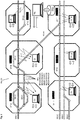
- Fig. 3 shows the rail network EN of Fig. 2 in a further illustration with several route sections that are already equipped with extended stationary network units NEX.
- the installed extended stationary network units NEX are symbolized by series with short vertical lines, which are equipped with extractors EXs and are wirelessly connected to concentrators CX, which in turn are connected wirelessly, directly or indirectly, to the stationary process computer PRs.
- Fig. 3 illustrates that the behavior of the stationary network units NEs can be detected not only by the stationary measuring devices MFs, but also by mobile measuring devices MFm.
- the relevant measured values are extracted at the level of the extractors EXs, EXm, for example using application programs Ax.
- the measured values determined in the stationary process computer PRs and in the mobile process computer PRm are evaluated by means of, for example, application programs Av, in order to obtain current status information or predictions for future ones To get developments of the states of the.
- Time series are preferably formed, which are evaluated on the basis of time series analyzes and expert knowledge. If an error of the relevant extended stationary network unit NEX is determined by expert knowledge, for example by detection of the exceeding of a tolerance value or agreement with an error pattern, a message SX ID is sent to the network computer NR. This message contains the identity of the relevant stationary network unit NEX and preferably error information.
- the network computer NR transmits this information to a maintenance module or a maintenance computer NM, which subsequently initiates measures for error correction of the relevant network unit NEX.
- Predictions can also be used to estimate the point in time at which individual network units NEX are expected to exceed tolerance values. These predictions SV ID are also transmitted via the network computer NR to the maintenance computer NM, which subsequently terminates the corresponding maintenance operations.
- the maintenance computer NM preferably checks in which sections of the railway network EN maintenance work should be carried out within a certain period of time. Appropriate planning and coordination of the maintenance work can reduce costs and effort when carrying out the maintenance work.
- Time series that have been determined for network units NEX are stored in a database PRD and are preferably continuously updated. Time series for which a current fault or failure of a NEX network unit has been registered are of particular interest. This error or failure can be determined by the process computer PRs. Alternatively, the failure of a NEX network unit can be reported to the process computer.
- Fig. 3 shows that for the network unit NEs with the Identification number IDX an error message F IDX was transmitted to the maintenance computer NM. For example, the failure of the NEX network unit was discovered during a route check and reported to the maintenance computer NM via a communication interface.
- the error message F IDX is subsequently transmitted to the process computer (s) PRs, PRm, which retrieves the last stored data ID X from the database PRD for the faulty network unit NEX and re-evaluates it based on the error message F IDX and as an error pattern FM IDX used if there are any abnormalities that indicate the error.
- the error pattern FM IDX can subsequently be used in the extractors EXs, EXm and the database PRD as a fingerprint or error pattern to extract or evaluate measured values.
- Error messages F IDX can also be obtained by the process computers PRs, PRm and used as an error pattern FM IDX .
- An arrow RG symbolizes that the monitoring device CS is thus able to generate rules and patterns itself.
- the rules R2 are loaded into the extractors EXs and loaded for the extraction of measured values and the rules R1 are loaded into the process computers PRs, PRm and used for the evaluation of measured values.
- the system is therefore self-learning and can continuously optimize itself over time.
Priority Applications (1)
| Application Number | Priority Date | Filing Date | Title |
|---|---|---|---|
| EP18183556.2A EP3594084A1 (fr) | 2018-07-13 | 2018-07-13 | Procédé et dispositif de surveillance d'un réseau ferroviaire et réseau ferroviaire |
Applications Claiming Priority (1)
| Application Number | Priority Date | Filing Date | Title |
|---|---|---|---|
| EP18183556.2A EP3594084A1 (fr) | 2018-07-13 | 2018-07-13 | Procédé et dispositif de surveillance d'un réseau ferroviaire et réseau ferroviaire |
Publications (1)
| Publication Number | Publication Date |
|---|---|
| EP3594084A1 true EP3594084A1 (fr) | 2020-01-15 |
Family
ID=63012808
Family Applications (1)
| Application Number | Title | Priority Date | Filing Date |
|---|---|---|---|
| EP18183556.2A Pending EP3594084A1 (fr) | 2018-07-13 | 2018-07-13 | Procédé et dispositif de surveillance d'un réseau ferroviaire et réseau ferroviaire |
Country Status (1)
| Country | Link |
|---|---|
| EP (1) | EP3594084A1 (fr) |
Cited By (1)
| Publication number | Priority date | Publication date | Assignee | Title |
|---|---|---|---|---|
| WO2023094055A1 (fr) * | 2021-11-26 | 2023-06-01 | Gts Deutschland Gmbh | Procédé d'exploitation d'un réseau ferroviaire comprenant la surveillance d'éléments d'infrastructure |
Citations (10)
| Publication number | Priority date | Publication date | Assignee | Title |
|---|---|---|---|---|
| DE19926164A1 (de) | 1999-06-09 | 2001-01-11 | Siemens Ag | Verfahren und Vorrichtung zum Überwachen eines Fahrzeugs und/oder zum Überwachen eines Fahrwegs während des betriebsmäßigen Fahrens des Fahrzeugs |
| EP1900597A1 (fr) * | 2006-09-18 | 2008-03-19 | Bombardier Transportation GmbH | Système de diagnostic et procédé pour surveiller un système ferroviaire |
| JP2013049395A (ja) * | 2011-08-31 | 2013-03-14 | Toshiba Corp | 列車制御システム |
| EP2631152A1 (fr) | 2012-02-24 | 2013-08-28 | Schweizerische Bundesbahnen SBB | Procédé et dispositif pour la gestion de ressources dans un réseau ferré |
| WO2014044485A2 (fr) | 2012-09-18 | 2014-03-27 | Siemens Aktiengesellschaft | Procédé permettant de diagnostiquer des éléments de tronçon d'un réseau ferroviaire |
| EP2894074A1 (fr) * | 2014-01-08 | 2015-07-15 | Schweizerische Bundesbahnen SBB | Procédé et dispositif de surveillance et de commande d'un réseau de voie ferrée |
| EP2943001A1 (fr) * | 2014-05-08 | 2015-11-11 | Icomera AB | Procédé et système de détection d'erreurs de réseau |
| WO2016115443A1 (fr) * | 2015-01-16 | 2016-07-21 | International Electronic Machines Corp. | Détection de dynamique de véhicule anormale |
| US20170149603A1 (en) * | 2014-05-19 | 2017-05-25 | Nec Corporation | Fault detection method and mobile wireless system |
| US20180048400A1 (en) * | 2015-03-05 | 2018-02-15 | Nec Corporation | Method of determining failure in radio facility and mobile radio system |
-
2018
- 2018-07-13 EP EP18183556.2A patent/EP3594084A1/fr active Pending
Patent Citations (10)
| Publication number | Priority date | Publication date | Assignee | Title |
|---|---|---|---|---|
| DE19926164A1 (de) | 1999-06-09 | 2001-01-11 | Siemens Ag | Verfahren und Vorrichtung zum Überwachen eines Fahrzeugs und/oder zum Überwachen eines Fahrwegs während des betriebsmäßigen Fahrens des Fahrzeugs |
| EP1900597A1 (fr) * | 2006-09-18 | 2008-03-19 | Bombardier Transportation GmbH | Système de diagnostic et procédé pour surveiller un système ferroviaire |
| JP2013049395A (ja) * | 2011-08-31 | 2013-03-14 | Toshiba Corp | 列車制御システム |
| EP2631152A1 (fr) | 2012-02-24 | 2013-08-28 | Schweizerische Bundesbahnen SBB | Procédé et dispositif pour la gestion de ressources dans un réseau ferré |
| WO2014044485A2 (fr) | 2012-09-18 | 2014-03-27 | Siemens Aktiengesellschaft | Procédé permettant de diagnostiquer des éléments de tronçon d'un réseau ferroviaire |
| EP2894074A1 (fr) * | 2014-01-08 | 2015-07-15 | Schweizerische Bundesbahnen SBB | Procédé et dispositif de surveillance et de commande d'un réseau de voie ferrée |
| EP2943001A1 (fr) * | 2014-05-08 | 2015-11-11 | Icomera AB | Procédé et système de détection d'erreurs de réseau |
| US20170149603A1 (en) * | 2014-05-19 | 2017-05-25 | Nec Corporation | Fault detection method and mobile wireless system |
| WO2016115443A1 (fr) * | 2015-01-16 | 2016-07-21 | International Electronic Machines Corp. | Détection de dynamique de véhicule anormale |
| US20180048400A1 (en) * | 2015-03-05 | 2018-02-15 | Nec Corporation | Method of determining failure in radio facility and mobile radio system |
Non-Patent Citations (9)
| Title |
|---|
| "MSP Low-Power Microcontrollers", 2015, TEXAS INSTRUMENTS INCORPORATED |
| HEINRICH NIEMANN: "Klassifikation von Mustern", 2003, SPRINGER VERLAG |
| J. SCOTT ARMSTRONG, PRINCIPLES OF FORECASTING, 2002 |
| J. SCOTT: "Armstrong, Principles of Forecasting", 2002 |
| MICHAEL SCHRÖDER: "Einführung in die kurzfristige Zeitreihenprognose und Vergleich der einzelnen Verfahren", 2012, SPRINGER-VERLAG BERLIN |
| P. MERTENS; S. RÄSSLER, PROGNOSERECHNUNG |
| P. MERTENS; S. RÄSSLER: "Prognoserechnung", 2012, SPRINGER-VERLAG, article "Einführung in die kurzfristige Zeitreihenprognose und Vergleich der einzelnen Verfahren" |
| R. HÄMMERLI: "Die Grundsätze der Sicherungsanlagen für den Eisenbahnbetrieb", SCHWEIZERISCHE BUNDESBAHNEN SBB, vol. 1, February 1990 (1990-02-01) |
| SCHWEIZERISCHE BUNDESBAHNEN SBB, vol. 2, November 1982 (1982-11-01) |
Cited By (1)
| Publication number | Priority date | Publication date | Assignee | Title |
|---|---|---|---|---|
| WO2023094055A1 (fr) * | 2021-11-26 | 2023-06-01 | Gts Deutschland Gmbh | Procédé d'exploitation d'un réseau ferroviaire comprenant la surveillance d'éléments d'infrastructure |
Similar Documents
| Publication | Publication Date | Title |
|---|---|---|
| EP2877384B1 (fr) | Procédé permettant de diagnostiquer des éléments de tronçon d'un réseau ferroviaire | |
| DE102017107284B4 (de) | Verfahren und steuergerät zum überwachen eines bordnetzes eines fahrzeugs | |
| WO2021121695A1 (fr) | Procédé, appareil et système de détection d'états de fonctionnement anormaux d'un dispositif | |
| DE102012202914A1 (de) | Diagnoseverfahren und Diagnosevorrichtung für eine Fahrzeugkomponente eines Fahrzeugs | |
| DE102017217444B4 (de) | Verfahren und System zum Aktualisieren eines Steuerungsmodells für eine automatische Steuerung zumindest einer mobilen Einheit | |
| DE102007051126A1 (de) | Bestimmung der Restlebensdauer einer Fahrzeugkomponente | |
| DE102009009449A1 (de) | Radsensor, Eisenbahnanlage mit zumindest einem Radsensor sowie Verfahren zum Betreiben einer Eisenbahnanlage | |
| EP3487748B1 (fr) | Surveillance d'infrastructures par regroupement géographique | |
| CN105572492A (zh) | 一种城轨列车辅助逆变器故障诊断装置 | |
| EP2894074B1 (fr) | Procédé et dispositif de surveillance d'un réseau de voie ferrée | |
| DE102017216801A1 (de) | Verfahren zum Überwachen mindestens einer Komponente eines Kraftfahrzeugs | |
| EP3594084A1 (fr) | Procédé et dispositif de surveillance d'un réseau ferroviaire et réseau ferroviaire | |
| EP3458331B1 (fr) | Procédé et dispositif de surveillance d'au moins un composant de voie posé dans la construction de chemin de fer | |
| DE102008032885A1 (de) | Verfahren und Vorrichtung zur Überprüfung und Feststellung von Zuständen eines Sensors | |
| EP2437228B1 (fr) | Alarme, installation d'alarme et procédé de reconnaissance d'erreurs de lignes de transmission | |
| DE102017212953A1 (de) | Ermittlung von odometrischen Daten eines Schienenfahrzeugs mit Hilfe stationärer Sensoren | |
| EP3507166B1 (fr) | Procédé et dispositif permettant de surveiller des états de véhicules ferroviaires | |
| EP3926304A1 (fr) | Procédé de détermination de la précision d'une détermination de position d'un repère, ainsi que système d'évaluation | |
| EP3312073A1 (fr) | Procédé de contrôle d'un système ferroviaire et système ferroviaire | |
| DE102018117579A1 (de) | Identifikation eines Schienenfahrzeugrades | |
| DE202021100535U1 (de) | Fehlerdiagnose- und Wartungsvorrichtung für ein Bremssystem eines Hochgeschwindigkeitszugs | |
| DE102018215017A1 (de) | Verfahren zur Bestimmung einer Betriebsstrategie für Fahrzeug, System, Steuereinrichtung für ein Fahrzeug und ein Fahrzeug | |
| DE102007047768B4 (de) | Prüfgerät für RFID-Systeme sowie RFID-Anordnungen und Verfahren zum Betreiben eines Prüfgeräts in einem RFID-System | |
| DE102018219256A1 (de) | Ermitteln einer Degradation einer bestimmten Gleiskomponente | |
| EP3963291B1 (fr) | Ensemble capteur conçu pour surveiller un système technique et procédé pour faire fonctionner un ensemble capteur |
Legal Events
| Date | Code | Title | Description |
|---|---|---|---|
| PUAI | Public reference made under article 153(3) epc to a published international application that has entered the european phase |
Free format text: ORIGINAL CODE: 0009012 |
|
| STAA | Information on the status of an ep patent application or granted ep patent |
Free format text: STATUS: THE APPLICATION HAS BEEN PUBLISHED |
|
| AK | Designated contracting states |
Kind code of ref document: A1 Designated state(s): AL AT BE BG CH CY CZ DE DK EE ES FI FR GB GR HR HU IE IS IT LI LT LU LV MC MK MT NL NO PL PT RO RS SE SI SK SM TR |
|
| AX | Request for extension of the european patent |
Extension state: BA ME |
|
| STAA | Information on the status of an ep patent application or granted ep patent |
Free format text: STATUS: REQUEST FOR EXAMINATION WAS MADE |
|
| 17P | Request for examination filed |
Effective date: 20200715 |
|
| RBV | Designated contracting states (corrected) |
Designated state(s): AL AT BE BG CH CY CZ DE DK EE ES FI FR GB GR HR HU IE IS IT LI LT LU LV MC MK MT NL NO PL PT RO RS SE SI SK SM TR |
|
| STAA | Information on the status of an ep patent application or granted ep patent |
Free format text: STATUS: EXAMINATION IS IN PROGRESS |
|
| 17Q | First examination report despatched |
Effective date: 20210514 |
|
| STAA | Information on the status of an ep patent application or granted ep patent |
Free format text: STATUS: EXAMINATION IS IN PROGRESS |