EP3594051B1 - Position-adjustable cervical vertebrae support apparatus capable of being installed in back of vehicle seat - Google Patents
Position-adjustable cervical vertebrae support apparatus capable of being installed in back of vehicle seat Download PDFInfo
- Publication number
- EP3594051B1 EP3594051B1 EP19175534.7A EP19175534A EP3594051B1 EP 3594051 B1 EP3594051 B1 EP 3594051B1 EP 19175534 A EP19175534 A EP 19175534A EP 3594051 B1 EP3594051 B1 EP 3594051B1
- Authority
- EP
- European Patent Office
- Prior art keywords
- cervical vertebrae
- supporting member
- cover portion
- screw rod
- handed screw
- Prior art date
- Legal status (The legal status is an assumption and is not a legal conclusion. Google has not performed a legal analysis and makes no representation as to the accuracy of the status listed.)
- Active
Links
Images


Classifications
-
- B—PERFORMING OPERATIONS; TRANSPORTING
- B60—VEHICLES IN GENERAL
- B60N—SEATS SPECIALLY ADAPTED FOR VEHICLES; VEHICLE PASSENGER ACCOMMODATION NOT OTHERWISE PROVIDED FOR
- B60N2/00—Seats specially adapted for vehicles; Arrangement or mounting of seats in vehicles
- B60N2/02—Seats specially adapted for vehicles; Arrangement or mounting of seats in vehicles the seat or part thereof being movable, e.g. adjustable
- B60N2/0224—Non-manual adjustments, e.g. with electrical operation
- B60N2/02246—Electric motors therefor
-
- B—PERFORMING OPERATIONS; TRANSPORTING
- B60—VEHICLES IN GENERAL
- B60N—SEATS SPECIALLY ADAPTED FOR VEHICLES; VEHICLE PASSENGER ACCOMMODATION NOT OTHERWISE PROVIDED FOR
- B60N2/00—Seats specially adapted for vehicles; Arrangement or mounting of seats in vehicles
- B60N2/80—Head-rests
- B60N2/806—Head-rests movable or adjustable
- B60N2/809—Head-rests movable or adjustable vertically slidable
- B60N2/829—Head-rests movable or adjustable vertically slidable characterised by their adjusting mechanisms, e.g. electric motors
-
- B—PERFORMING OPERATIONS; TRANSPORTING
- B60—VEHICLES IN GENERAL
- B60N—SEATS SPECIALLY ADAPTED FOR VEHICLES; VEHICLE PASSENGER ACCOMMODATION NOT OTHERWISE PROVIDED FOR
- B60N2/00—Seats specially adapted for vehicles; Arrangement or mounting of seats in vehicles
- B60N2/02—Seats specially adapted for vehicles; Arrangement or mounting of seats in vehicles the seat or part thereof being movable, e.g. adjustable
- B60N2/22—Seats specially adapted for vehicles; Arrangement or mounting of seats in vehicles the seat or part thereof being movable, e.g. adjustable the back-rest being adjustable
- B60N2/2222—Seats specially adapted for vehicles; Arrangement or mounting of seats in vehicles the seat or part thereof being movable, e.g. adjustable the back-rest being adjustable the back-rest having two or more parts
-
- A—HUMAN NECESSITIES
- A47—FURNITURE; DOMESTIC ARTICLES OR APPLIANCES; COFFEE MILLS; SPICE MILLS; SUCTION CLEANERS IN GENERAL
- A47C—CHAIRS; SOFAS; BEDS
- A47C7/00—Parts, details, or accessories of chairs or stools
- A47C7/36—Supports for the head or the back
- A47C7/40—Supports for the head or the back for the back
- A47C7/42—Supports for the head or the back for the back of detachable or loose type
- A47C7/425—Supplementary back-rests to be positioned on a back-rest or the like
-
- B—PERFORMING OPERATIONS; TRANSPORTING
- B60—VEHICLES IN GENERAL
- B60N—SEATS SPECIALLY ADAPTED FOR VEHICLES; VEHICLE PASSENGER ACCOMMODATION NOT OTHERWISE PROVIDED FOR
- B60N2/00—Seats specially adapted for vehicles; Arrangement or mounting of seats in vehicles
- B60N2/02—Seats specially adapted for vehicles; Arrangement or mounting of seats in vehicles the seat or part thereof being movable, e.g. adjustable
- B60N2/22—Seats specially adapted for vehicles; Arrangement or mounting of seats in vehicles the seat or part thereof being movable, e.g. adjustable the back-rest being adjustable
-
- B—PERFORMING OPERATIONS; TRANSPORTING
- B60—VEHICLES IN GENERAL
- B60N—SEATS SPECIALLY ADAPTED FOR VEHICLES; VEHICLE PASSENGER ACCOMMODATION NOT OTHERWISE PROVIDED FOR
- B60N2/00—Seats specially adapted for vehicles; Arrangement or mounting of seats in vehicles
- B60N2/56—Heating or ventilating devices
-
- B—PERFORMING OPERATIONS; TRANSPORTING
- B60—VEHICLES IN GENERAL
- B60N—SEATS SPECIALLY ADAPTED FOR VEHICLES; VEHICLE PASSENGER ACCOMMODATION NOT OTHERWISE PROVIDED FOR
- B60N2/00—Seats specially adapted for vehicles; Arrangement or mounting of seats in vehicles
- B60N2/64—Back-rests or cushions
- B60N2/643—Back-rests or cushions shape of the back-rests
-
- B—PERFORMING OPERATIONS; TRANSPORTING
- B60—VEHICLES IN GENERAL
- B60N—SEATS SPECIALLY ADAPTED FOR VEHICLES; VEHICLE PASSENGER ACCOMMODATION NOT OTHERWISE PROVIDED FOR
- B60N2/00—Seats specially adapted for vehicles; Arrangement or mounting of seats in vehicles
- B60N2/80—Head-rests
- B60N2/806—Head-rests movable or adjustable
- B60N2/865—Head-rests movable or adjustable providing a fore-and-aft movement with respect to the occupant's head
-
- B—PERFORMING OPERATIONS; TRANSPORTING
- B60—VEHICLES IN GENERAL
- B60N—SEATS SPECIALLY ADAPTED FOR VEHICLES; VEHICLE PASSENGER ACCOMMODATION NOT OTHERWISE PROVIDED FOR
- B60N2/00—Seats specially adapted for vehicles; Arrangement or mounting of seats in vehicles
- B60N2/80—Head-rests
- B60N2/879—Head-rests with additional features not related to head-rest positioning, e.g. heating or cooling devices or loudspeakers
-
- B—PERFORMING OPERATIONS; TRANSPORTING
- B60—VEHICLES IN GENERAL
- B60N—SEATS SPECIALLY ADAPTED FOR VEHICLES; VEHICLE PASSENGER ACCOMMODATION NOT OTHERWISE PROVIDED FOR
- B60N2/00—Seats specially adapted for vehicles; Arrangement or mounting of seats in vehicles
- B60N2/90—Details or parts not otherwise provided for
- B60N2/976—Details or parts not otherwise provided for massaging systems
-
- B—PERFORMING OPERATIONS; TRANSPORTING
- B60—VEHICLES IN GENERAL
- B60N—SEATS SPECIALLY ADAPTED FOR VEHICLES; VEHICLE PASSENGER ACCOMMODATION NOT OTHERWISE PROVIDED FOR
- B60N2/00—Seats specially adapted for vehicles; Arrangement or mounting of seats in vehicles
- B60N2/02—Seats specially adapted for vehicles; Arrangement or mounting of seats in vehicles the seat or part thereof being movable, e.g. adjustable
- B60N2/22—Seats specially adapted for vehicles; Arrangement or mounting of seats in vehicles the seat or part thereof being movable, e.g. adjustable the back-rest being adjustable
- B60N2002/2204—Adjustable back-rest height or length
-
- B—PERFORMING OPERATIONS; TRANSPORTING
- B60—VEHICLES IN GENERAL
- B60N—SEATS SPECIALLY ADAPTED FOR VEHICLES; VEHICLE PASSENGER ACCOMMODATION NOT OTHERWISE PROVIDED FOR
- B60N2205/00—General mechanical or structural details
- B60N2205/30—Seat or seat parts characterised by comprising plural parts or pieces
Definitions
- the present invention relates generally to a position-adjustable cervical vertebrae support apparatus capable of being installed in the back of a vehicle seat, and more specifically to a position-adjustable cervical vertebrae support apparatus capable of being installed on the back of a vehicle seat, which adjusts the position of the posterior cervical vertebra (the neck bone) of a driver and then supports the posterior cervical vertebra on the back of a vehicle seat in accordance with the body characteristics of the driver, so that the driving posture of the driver may be corrected in accordance with the body characteristics of the driver and a stable driving posture may be continuously maintained, thereby relieving driving fatigue.
- JP 2008194298 A shows a neck rest with a fore and aft adjustment functionality and an up and down adjustment functionality.
- the seats of a vehicle can support a driver or passengers safely and comfortably within limited space and weight ranges.
- These seats include a driver's seat, a front passenger seat, and back seats.
- the seats are classified into bench seats formed in long chair shapes and separate seats configured to be separate from each other according to their shape.
- Such a seat of a vehicle includes a seat base configured to support the buttocks of a sitting person and a back configured to support the back of the sitting person.
- the driver When a driver drives a vehicle while holding his or her body on a seat of the vehicle, the driver usually drives the vehicle in a state in which his or her lumbar vertebrae, i.e., the lower part of his or her spine, have been brought into close contact with the back of the seat and his or her thoracic vertebrae or cervical vertebrae present above the lumbar vertebrae have been separated from the back of the seat.
- his or her lumbar vertebrae i.e., the lower part of his or her spine
- his or her thoracic vertebrae or cervical vertebrae present above the lumbar vertebrae have been separated from the back of the seat.
- the case is more severe.
- Patent Document 1 Korean Patent No. 10-0162170
- the present invention has been conceived to overcome the above-described problems, and an object of the present invention is to provide a position-adjustable cervical vertebrae support apparatus capable of being installed on the back of a vehicle seat, which adjusts the position of the posterior cervical vertebra (the neck bone) of a driver and then supports the posterior cervical vertebra on the back of a vehicle seat in accordance with the body characteristics of the driver, so that the driving posture of the driver may be corrected in accordance with the body characteristics of the driver and a stable driving posture may be continuously maintained, thereby relieving driving fatigue.
- the present invention provides a position-adjustable cervical vertebrae support apparatus capable of being installed in a back of a vehicle seat, the cervical vertebrae support apparatus being constructed in the back of the vehicle seat in accordance with the features of claim 1.
- the back of the upper end of the cervical vertebrae supporting member the distance of which is vertically adjusted on the back by the up-down distance adjusting unit may be seated on a downward movement limiting plate horizontally formed on the inside of a back support plate portion adapted to extend vertically from the upper end of the back side of the back, so that the downward movement of the cervical vertebrae supporting member may be limited.
- the back of the upper end of the cervical vertebrae supporting member may be configured to be seated in a seat groove portion depressed into the upper end of the back support plate portion adapted to extend vertically from the upper end of the back side of the back.
- heating and vibration means may be provided inside the cervical vertebrae supporting member.
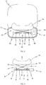
- FIG. 1 is an exemplary perspective view showing the back of a vehicle seat on which a position-adjustable cervical vertebrae support apparatus according to the present invention has been installed
- FIG. 2 is an exemplary sectional view showing FIG. 1 when viewed from above
- FIG. 3 is an exemplary sectional view showing the configuration of the important portion of the present invention when viewed from above
- FIG. 4 shows exemplary views showing states in which the cervical vertebrae supporting member of the present invention has been moved forward and backward
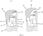
- FIG. 5 shows exemplary views showing states in which the cervical vertebrae supporting member of the present invention has been moved upward and downward.
- a position-adjustable cervical vertebrae support apparatus capable of being installed in the back of a vehicle seat, which adjusts the position of the posterior cervical vertebra (the neck bone) of a driver and supports the posterior cervical vertebra on the back of a vehicle seat in accordance with the body characteristics of the driver, so that the driving posture of the driver may be corrected in accordance with the body characteristics of the driver and a stable driving posture may be continuously maintained, thereby relieving driving fatigue, is configured to include a cervical vertebrae supporting member 50, an front-back distance adjusting unit 60, and an up-down distance adjusting unit 80.
- the cervical vertebrae support apparatus is constructed in the back of a vehicle seat including a seat base 10, a back 20, and a headrest 30, as shown in FIG. 1 .
- the cervical vertebrae supporting member 50 is configured to be located in an installation space part 92 open in the upper and front end portions of the back 20 and to support the cervical vertebrae of a driver, as shown in FIG. 2 .
- the cervical vertebrae supporting member 50 is a means for correcting a driving posture and continuously maintaining a stable driving posture by supporting the back of the cervical vertebrae (a neck bone) of a driver on the back 20.
- at least one of a heating means (not shown) and a vibration means (not shown) may be provided inside the cervical vertebrae supporting member 50, and may allow a driver to perform a fomentation or massage function while resting in a vehicle.
- the front-back distance adjusting unit 60 and the up-down distance adjusting unit 80 are included in the cervical vertebrae supporting member 50.
- a mounting plate 68 is brought into close contact with and fastened to the back of the cervical vertebrae supporting member 50
- a left-handed screw rod 61 and a right-handed screw rod 62 are located at a distance from the back of the mounting plate 68
- movable nuts 63 and 64 are disposed around the left-handed screw rod 61 and the right-handed screw rod 62, respectively, as shown in FIGS. 3 and 4 .
- distance adjustment rods 74 are coupled to the movable nuts 63 and 64, also coupled to both sides hinges 76 provided on the back of the mounting plate 68 in a crossed manner and rotatable around a central pin 72, and the left-handed screw rod 61 and the right-handed screw rod 62 are rotated by a motor 67.
- the cervical vertebrae supporting member 50 is moved forward or backward, as shown in FIGS. 3 and 4(b) .
- a plate-shaped front vertical cover portion 52 is formed on the front of the lower end of the cervical vertebrae supporting member 50 the distance of which is adjusted on the back 20 by the front-back distance adjusting unit 60, a plate-shaped back vertical cover portion 54 is formed at a distance from the back of the front vertical cover portion 52, and a front support plate portion 21 extending vertically from the top of the front of the back 20 is inserted between the front vertical cover portion 52 and the back vertical cover portion 54.
- the front support plate portion 21 is brought into close contact with the inner surfaces of the front vertical cover portion 52 and the back vertical cover portion 54 by the forward and backward movement of the front vertical cover portion 52 and the back vertical cover portion 54, and thus the forward and backward movement of the cervical vertebrae supporting member 50 is limited.
- a vertical mounting plate 81 is provided to support a side of the motor 67
- a bottom mounting base 83 is provided to support the bottom side of the vertical mounting plate 81
- a rod 85 coupled to a cylinder 87 is connected to the bottom of the bottom mounting base 83 in order to lift or lower the bottom mounting base 83, as shown in FIG. 5 . Accordingly, the cervical vertebrae supporting member 50 is vertically moved by the operation of the cylinder 87.
- the cervical vertebrae supporting member 50 is vertically moved, as shown in FIG. 5(b) .
- the back of the upper end of the cervical vertebrae supporting member 50 the distance of which is vertically adjusted on the back 20 by the up-down distance adjusting unit 80 is seated on a downward movement limiting plate 25 horizontally formed on the inside of a back support plate portion 23 extending vertically from the upper end of the back side of the back 20, and thus the downward movement of the cervical vertebrae supporting member 50 is limited.
- the downward movement limiting plate 25 performs the function of limiting the downward movement of the cervical vertebrae supporting member 50, and also performs the function of allowing the cervical vertebrae supporting member 50 to slide while supporting the back of the cervical vertebrae supporting member 50 during the forward and backward movement of the cervical vertebrae supporting member 50 by the front-back distance adjusting unit 60, as shown in FIG. 4(b) .
- the posterior cervical vertebra (the neck bone) of a driver is adjusted in position and supported on the back of a vehicle seat in accordance with the body characteristics of the driver, so that the driving posture of the driver may be corrected in accordance with the body characteristics of the driver and a stable driving posture may be continuously maintained, thereby relieving driving fatigue.
Landscapes
- Engineering & Computer Science (AREA)
- Aviation & Aerospace Engineering (AREA)
- Transportation (AREA)
- Mechanical Engineering (AREA)
- Orthopedics, Nursing, And Contraception (AREA)
- Seats For Vehicles (AREA)
Description
- It is refered to Korean Patent Application No.
10-2018-0075482 filed on June 29, 2018 - The present invention relates generally to a position-adjustable cervical vertebrae support apparatus capable of being installed in the back of a vehicle seat, and more specifically to a position-adjustable cervical vertebrae support apparatus capable of being installed on the back of a vehicle seat, which adjusts the position of the posterior cervical vertebra (the neck bone) of a driver and then supports the posterior cervical vertebra on the back of a vehicle seat in accordance with the body characteristics of the driver, so that the driving posture of the driver may be corrected in accordance with the body characteristics of the driver and a stable driving posture may be continuously maintained, thereby relieving driving fatigue.
JP 2008194298 A - In general, the seats of a vehicle can support a driver or passengers safely and comfortably within limited space and weight ranges. These seats include a driver's seat, a front passenger seat, and back seats. Furthermore, the seats are classified into bench seats formed in long chair shapes and separate seats configured to be separate from each other according to their shape.
- Such a seat of a vehicle includes a seat base configured to support the buttocks of a sitting person and a back configured to support the back of the sitting person.
- When a driver drives a vehicle while holding his or her body on a seat of the vehicle, the driver usually drives the vehicle in a state in which his or her lumbar vertebrae, i.e., the lower part of his or her spine, have been brought into close contact with the back of the seat and his or her thoracic vertebrae or cervical vertebrae present above the lumbar vertebrae have been separated from the back of the seat. In particular, in the case of a beginning driver, the case is more severe.
- Such an incorrect driving posture easily causes a driver's fatigue, and thus a problem arises in that the driver who is suffering from fatigue is more likely to cause a major accident because instantaneous judgment is slowed down or becomes inaccurate.
- (Patent Document 1) Korean Patent No.
10-0162170 - The present invention has been conceived to overcome the above-described problems, and an object of the present invention is to provide a position-adjustable cervical vertebrae support apparatus capable of being installed on the back of a vehicle seat, which adjusts the position of the posterior cervical vertebra (the neck bone) of a driver and then supports the posterior cervical vertebra on the back of a vehicle seat in accordance with the body characteristics of the driver, so that the driving posture of the driver may be corrected in accordance with the body characteristics of the driver and a stable driving posture may be continuously maintained, thereby relieving driving fatigue.
- In order to accomplish the above object, the present invention provides a position-adjustable cervical vertebrae support apparatus capable of being installed in a back of a vehicle seat, the cervical vertebrae support apparatus being constructed in the back of the vehicle seat in accordance with the features of claim 1.
- The back of the upper end of the cervical vertebrae supporting member the distance of which is vertically adjusted on the back by the up-down distance adjusting unit may be seated on a downward movement limiting plate horizontally formed on the inside of a back support plate portion adapted to extend vertically from the upper end of the back side of the back, so that the downward movement of the cervical vertebrae supporting member may be limited.
- The back of the upper end of the cervical vertebrae supporting member may be configured to be seated in a seat groove portion depressed into the upper end of the back support plate portion adapted to extend vertically from the upper end of the back side of the back.
- Any one of heating and vibration means may be provided inside the cervical vertebrae supporting member.
- The above and other objects, features, and advantages of the present invention will be more clearly understood from the following detailed description taken in conjunction with the accompanying drawings, in which:
-
FIG. 1 is an exemplary perspective view showing the back of a vehicle seat on which a position-adjustable cervical vertebrae support apparatus according to the present invention has been installed; -
FIG. 2 is an exemplary sectional view showingFIG. 1 when viewed from above; -
FIG. 3 is an exemplary sectional view showing the configuration of the important portion of the present invention when viewed from above; -
FIG. 4 shows exemplary views showing states in which the cervical vertebrae supporting member of the present invention has been moved forward and backward; and -
FIG. 5 shows exemplary views showing states in which the cervical vertebrae supporting member of the present invention has been moved upward and downward. - Details for the practice of the present invention will be described in detail below with reference to the accompanying drawings.
-
FIG. 1 is an exemplary perspective view showing the back of a vehicle seat on which a position-adjustable cervical vertebrae support apparatus according to the present invention has been installed,FIG. 2 is an exemplary sectional view showingFIG. 1 when viewed from above,FIG. 3 is an exemplary sectional view showing the configuration of the important portion of the present invention when viewed from above,FIG. 4 shows exemplary views showing states in which the cervical vertebrae supporting member of the present invention has been moved forward and backward, andFIG. 5 shows exemplary views showing states in which the cervical vertebrae supporting member of the present invention has been moved upward and downward. Referring toFIGS. 1 to 5 , a position-adjustable cervical vertebrae support apparatus capable of being installed in the back of a vehicle seat, which adjusts the position of the posterior cervical vertebra (the neck bone) of a driver and supports the posterior cervical vertebra on the back of a vehicle seat in accordance with the body characteristics of the driver, so that the driving posture of the driver may be corrected in accordance with the body characteristics of the driver and a stable driving posture may be continuously maintained, thereby relieving driving fatigue, is configured to include a cervicalvertebrae supporting member 50, an front-backdistance adjusting unit 60, and an up-downdistance adjusting unit 80. - First, the cervical vertebrae support apparatus according to the present invention is constructed in the back of a vehicle seat including a
seat base 10, aback 20, and aheadrest 30, as shown inFIG. 1 . To implement the apparatus, the cervicalvertebrae supporting member 50 is configured to be located in aninstallation space part 92 open in the upper and front end portions of theback 20 and to support the cervical vertebrae of a driver, as shown inFIG. 2 . - The cervical
vertebrae supporting member 50 is a means for correcting a driving posture and continuously maintaining a stable driving posture by supporting the back of the cervical vertebrae (a neck bone) of a driver on theback 20. In addition, at least one of a heating means (not shown) and a vibration means (not shown) may be provided inside the cervicalvertebrae supporting member 50, and may allow a driver to perform a fomentation or massage function while resting in a vehicle. - The front-back
distance adjusting unit 60 and the up-downdistance adjusting unit 80 are included in the cervicalvertebrae supporting member 50. First, to construct the front-backdistance adjusting unit 60, amounting plate 68 is brought into close contact with and fastened to the back of the cervicalvertebrae supporting member 50, a left-handed screw rod 61 and a right-handed screw rod 62 are located at a distance from the back of themounting plate 68, andmovable nuts handed screw rod 61 and the right-handed screw rod 62, respectively, as shown inFIGS. 3 and4 . - Furthermore,
distance adjustment rods 74 are coupled to themovable nuts sides hinges 76 provided on the back of themounting plate 68 in a crossed manner and rotatable around acentral pin 72, and the left-handed screw rod 61 and the right-handed screw rod 62 are rotated by amotor 67. - According to the above configuration, as the
distance adjustment rods 74 are rotated in a crossed state by the rotation of the left-handed screw rod 61 and the right-handed screw rod 62 by themotor 67, the cervicalvertebrae supporting member 50 is moved forward or backward, as shown inFIGS. 3 and4(b) . - In this case, as shown in
FIG. 4 , in an embodiment, a plate-shaped frontvertical cover portion 52 is formed on the front of the lower end of the cervicalvertebrae supporting member 50 the distance of which is adjusted on theback 20 by the front-backdistance adjusting unit 60, a plate-shaped backvertical cover portion 54 is formed at a distance from the back of the frontvertical cover portion 52, and a frontsupport plate portion 21 extending vertically from the top of the front of theback 20 is inserted between the frontvertical cover portion 52 and the backvertical cover portion 54. Accordingly, the frontsupport plate portion 21 is brought into close contact with the inner surfaces of the frontvertical cover portion 52 and the backvertical cover portion 54 by the forward and backward movement of the frontvertical cover portion 52 and the backvertical cover portion 54, and thus the forward and backward movement of the cervicalvertebrae supporting member 50 is limited. - Furthermore, to construct the up-down
distance adjusting unit 80, avertical mounting plate 81 is provided to support a side of themotor 67, abottom mounting base 83 is provided to support the bottom side of thevertical mounting plate 81, and arod 85 coupled to acylinder 87 is connected to the bottom of thebottom mounting base 83 in order to lift or lower thebottom mounting base 83, as shown inFIG. 5 . Accordingly, the cervicalvertebrae supporting member 50 is vertically moved by the operation of thecylinder 87. - According to this configuration, as the
bottom mounting base 83 and thevertical mounting plate 81 coupled to therod 85 are selectively lifted and lowered by the operation of thecylinder 87, the cervicalvertebrae supporting member 50 is vertically moved, as shown inFIG. 5(b) . - In this case, as shown in
FIG. 5 , in an embodiment, the back of the upper end of the cervicalvertebrae supporting member 50 the distance of which is vertically adjusted on theback 20 by the up-downdistance adjusting unit 80 is seated on a downwardmovement limiting plate 25 horizontally formed on the inside of a backsupport plate portion 23 extending vertically from the upper end of the back side of theback 20, and thus the downward movement of the cervicalvertebrae supporting member 50 is limited. - The downward
movement limiting plate 25 performs the function of limiting the downward movement of the cervicalvertebrae supporting member 50, and also performs the function of allowing the cervicalvertebrae supporting member 50 to slide while supporting the back of the cervicalvertebrae supporting member 50 during the forward and backward movement of the cervicalvertebrae supporting member 50 by the front-backdistance adjusting unit 60, as shown inFIG. 4(b) . - Meanwhile, as shown in
FIGS. 4 and5 , when the back of the upper end of the cervicalvertebrae supporting member 50 is configured to be seated in a seat groove portion 24 depressed into the upper end of the backsupport plate portion 23 extending vertically from the upper end of the back side of theback 20, the force used to stably support the cervicalvertebrae supporting member 50 is obtained. - According to the present invention described above, the posterior cervical vertebra (the neck bone) of a driver is adjusted in position and supported on the back of a vehicle seat in accordance with the body characteristics of the driver, so that the driving posture of the driver may be corrected in accordance with the body characteristics of the driver and a stable driving posture may be continuously maintained, thereby relieving driving fatigue.
- The above-described present invention is not limited to the above-described embodiments and the accompanying drawings. It will be apparent to those having ordinary knowledge in the art to which the present invention pertains that various substitutions, alterations, and modifications may be made within the scope of the claims.
Claims (4)
- A position-adjustable cervical vertebrae support apparatus capable of being installed in a back of a vehicle seat, the cervical vertebrae support apparatus being constructed in the back of the vehicle seat including a seat base (10), a back (20), and a headrest (30), the cervical vertebrae support apparatus comprising:a cervical vertebrae supporting member (50) which is adapted to be located in an installation space part (92) open in upper and front end portions of the back (20) and which supports cervical vertebrae of a driver;a front-back distance adjusting unit (60) in which a mounting plate (68) is brought into close contact with and fastened to a back of the cervical vertebrae supporting member (50), a left-handed screw rod (61) and a right-handed screw rod (62) are located at a distance from a back of the mounting plate (68), movable nuts (63 and 64) are disposed around the left-handed screw rod (61) and the right-handed screw rod (62), respectively, distance adjustment rods (74) are coupled to the movable nuts (63 and 64), also coupled to both sides hinges (76) provided on the back of the mounting plate (68) in a crossed manner and rotatable around a central pin (72), and the left-handed screw rod (61) and the right-handed screw rod (62) are rotated by a motor (67), so that, as the distance adjustment rods (74) are rotated in a crossed state by rotation of the left-handed screw rod (61) and the right-handed screw rod (62) by the motor (67), the cervical vertebrae supporting member (50) is moved forward or backward; andan up-down distance adjusting unit (80) in which a vertical mounting plate (81) is provided to support a side of the motor (67), a bottom mounting base (83) is provided to support a bottom side of the vertical mounting plate (81), and a rod (85) coupled to a cylinder (87) is connected to a bottom of the bottom mounting base (83) in order to lift or lower the bottom mounting base (83), so that the cervical vertebrae supporting member (50) is vertically moved by operation of the cylinder (87);wherein a plate-shaped front vertical cover portion (52) is formed on a front of a lower end of the cervical vertebrae supporting member (50) a distance of which is adjusted on the back (20) by the front-back distance adjusting unit (60), a plate-shaped back vertical cover portion (54) is formed at a distance from a back of the front vertical cover portion (52), and a front support plate portion (21) adapted to extend vertically from a top of a front of the back (20) is inserted between the front vertical cover portion (52) and the back vertical cover portion (54), so that the front support plate portion (21) is brought into close contact with inner surfaces of the front vertical cover portion (52) and the back vertical cover portion (54) by forward and backward movement of the front vertical cover portion (52) and the back vertical cover portion (54), and thus forward and backward movement of the cervical vertebrae supporting member (50) is limited.
- The position-adjustable cervical vertebrae support apparatus of claim 1, wherein a back of an upper end of the cervical vertebrae supporting member (50) a distance of which is vertically adjusted on the back (20) by the up-down distance adjusting unit (80) is seated on a downward movement limiting plate (25) horizontally formed on an inside of a back support plate portion (23) adapted to extend vertically from an upper end of a back side of the back (20), so that downward movement of the cervical vertebrae supporting member (50) is limited.
- The position-adjustable cervical vertebrae support apparatus of claim 2, wherein a back of an upper end of the cervical vertebrae supporting member (50) is configured to be seated in a seat groove portion (24) depressed into an upper end of the back support plate portion (23) adapted to extend vertically from the upper end of the back side of the back (20).
- The position-adjustable cervical vertebrae support apparatus of claim 3, wherein any one of heating and vibration means is provided inside the cervical vertebrae supporting member (50).
Applications Claiming Priority (1)
| Application Number | Priority Date | Filing Date | Title |
|---|---|---|---|
| KR1020180075482A KR101935205B1 (en) | 2018-06-29 | 2018-06-29 | cervical vertebrae support apparatus capable of position control |
Publications (2)
| Publication Number | Publication Date |
|---|---|
| EP3594051A1 EP3594051A1 (en) | 2020-01-15 |
| EP3594051B1 true EP3594051B1 (en) | 2020-10-21 |
Family
ID=65021094
Family Applications (1)
| Application Number | Title | Priority Date | Filing Date |
|---|---|---|---|
| EP19175534.7A Active EP3594051B1 (en) | 2018-06-29 | 2019-05-21 | Position-adjustable cervical vertebrae support apparatus capable of being installed in back of vehicle seat |
Country Status (5)
| Country | Link |
|---|---|
| US (1) | US10688898B2 (en) |
| EP (1) | EP3594051B1 (en) |
| JP (1) | JP7281962B2 (en) |
| KR (1) | KR101935205B1 (en) |
| CN (1) | CN110654286B (en) |
Families Citing this family (7)
| Publication number | Priority date | Publication date | Assignee | Title |
|---|---|---|---|---|
| DE102019123680A1 (en) | 2019-09-04 | 2021-03-04 | Brose Fahrzeugteile SE & Co. Kommanditgesellschaft, Coburg | Adjustable neck support |
| JP2021130430A (en) * | 2020-02-21 | 2021-09-09 | テイ・エス テック株式会社 | Neckrest drive mechanism, neckrest, headrest, and vehicle seat |
| JP7444026B2 (en) | 2020-11-04 | 2024-03-06 | トヨタ紡織株式会社 | Lumbar support device |
| JP7684546B2 (en) * | 2021-02-04 | 2025-05-28 | テイ・エス テック株式会社 | Vehicle seat device |
| CN113547960A (en) * | 2021-07-20 | 2021-10-26 | 武汉大糖果科技有限公司 | Car intelligence seat adjusts structure based on human-machine engineering |
| US11939063B2 (en) | 2022-04-26 | 2024-03-26 | Gulfstream Aerospace Corporation | Reclining seat |
| KR102949608B1 (en) | 2022-12-09 | 2026-04-06 | 함아름 | In-vehicle cervical spine correction device |
Family Cites Families (23)
| Publication number | Priority date | Publication date | Assignee | Title |
|---|---|---|---|---|
| US5567011A (en) * | 1990-03-09 | 1996-10-22 | Sessini; Lorenza | Cushion for anatomical support, especially for the lumbar and cervical regions, to fit onto seat backs |
| JPH0767744A (en) * | 1993-08-31 | 1995-03-14 | Nisshin Plant Co Ltd | Automatic movable headrest for vehicle |
| KR0162170B1 (en) | 1995-12-13 | 1998-12-01 | 김태구 | Car cushion seat with thoracic spine support |
| US5964504A (en) * | 1997-03-26 | 1999-10-12 | Hogan & Schuman Development L.L.C. | Neck support device for use with an automobile seat |
| KR19990018485U (en) | 1997-11-11 | 1999-06-05 | 정몽규 | Seat Back Height Adjuster |
| US6530622B1 (en) * | 2001-03-16 | 2003-03-11 | Johnson Controls Technology Company | Biomechanical vehicle seat |
| US7048337B2 (en) * | 2003-02-14 | 2006-05-23 | Designworks/Usa, Inc. | Retractable headrest |
| KR20040095128A (en) * | 2003-05-06 | 2004-11-12 | 조휘창 | Automatic Adjusting system (Memory System) of Car Seat Head Restraint Position |
| JP2008194298A (en) * | 2007-02-14 | 2008-08-28 | Aisin Seiki Co Ltd | Vehicle seat |
| JP5087974B2 (en) * | 2007-04-06 | 2012-12-05 | トヨタ紡織株式会社 | Vehicle seat |
| GB2460600B (en) * | 2007-04-19 | 2011-09-21 | Ronald P Dellanno | Vehicle seat for reducing the risk of spinal and head injuries of personnel in combat vehicles |
| DE102008012715B3 (en) * | 2008-03-03 | 2009-07-16 | Keiper Gmbh & Co. Kg | Vehicle seat, in particular motor vehicle seat |
| KR20100033584A (en) | 2008-09-22 | 2010-03-31 | 다이모스(주) | Cross link typed back supporting device of seat in vehicle |
| CN201511850U (en) * | 2009-09-22 | 2010-06-23 | 陈三豹 | Seat back cushion |
| US8474909B2 (en) * | 2010-09-21 | 2013-07-02 | La-Z-Boy Incorporated | Power lift lumbar support system |
| DE102013000163A1 (en) * | 2013-01-09 | 2014-07-10 | Faurecia Autositze Gmbh | Seat arrangement for a vehicle |
| JP6053657B2 (en) * | 2013-10-15 | 2016-12-27 | 本田技研工業株式会社 | Neck support device for vehicle seat |
| US9131777B2 (en) * | 2013-10-25 | 2015-09-15 | Toyota Motor Engineering & Manufacturing North America, Inc. | Variable lumbar support assembly |
| JP6202734B2 (en) * | 2013-11-18 | 2017-09-27 | 株式会社タチエス | Sheet |
| US20150197170A1 (en) * | 2014-01-13 | 2015-07-16 | Andrey Obukhov | Vehicle chair neck supporting device and method of using the same |
| US10035442B2 (en) * | 2016-01-25 | 2018-07-31 | Ford Global Technologies, Llc | Adjustable upper seatback module |
| CN206242966U (en) * | 2016-12-21 | 2017-06-13 | 李斌 | Automobile driver seat seat |
| CN207374173U (en) * | 2017-11-10 | 2018-05-18 | 河南恒翔塑业科技有限公司 | A kind of child's safety seat for vehicle headrest height adjustment device |
-
2018
- 2018-06-29 KR KR1020180075482A patent/KR101935205B1/en active Active
-
2019
- 2019-05-20 JP JP2019094359A patent/JP7281962B2/en active Active
- 2019-05-21 US US16/417,753 patent/US10688898B2/en active Active
- 2019-05-21 EP EP19175534.7A patent/EP3594051B1/en active Active
- 2019-05-27 CN CN201910446663.9A patent/CN110654286B/en active Active
Non-Patent Citations (1)
| Title |
|---|
| None * |
Also Published As
| Publication number | Publication date |
|---|---|
| US10688898B2 (en) | 2020-06-23 |
| US20200001757A1 (en) | 2020-01-02 |
| JP2020001686A (en) | 2020-01-09 |
| EP3594051A1 (en) | 2020-01-15 |
| JP7281962B2 (en) | 2023-05-26 |
| CN110654286A (en) | 2020-01-07 |
| CN110654286B (en) | 2021-11-02 |
| KR101935205B1 (en) | 2019-01-08 |
Similar Documents
| Publication | Publication Date | Title |
|---|---|---|
| EP3594051B1 (en) | Position-adjustable cervical vertebrae support apparatus capable of being installed in back of vehicle seat | |
| US9809131B2 (en) | Anthropomorphic pivotable upper seatback support | |
| CN108528284B (en) | Seat back lifting mechanism for a recumbent motor vehicle seat assembly | |
| EP2802480B1 (en) | Reclining seat assembly | |
| EP3031724B1 (en) | A reclinable seat | |
| US7819474B2 (en) | Adjustable thigh support for a motor vehicle seat | |
| US9987955B2 (en) | Motor vehicle seat | |
| JP6754758B2 (en) | Beds and bed inserts with postural support | |
| US11440442B2 (en) | Vehicle seat console, vehicle seat, and vehicle | |
| US11820257B2 (en) | Vehicle seat arrangement | |
| GB2512136A (en) | Seat apparatus for a vehicle | |
| US10703246B2 (en) | Vehicle comprising a deformable feet support device | |
| CN110087942A (en) | seat headrest | |
| US9132757B2 (en) | Vehicle seat comprising a head restraint | |
| JP2009514738A (en) | Vehicle seat | |
| KR200141071Y1 (en) | Seat with waist supporting device | |
| KR19980036815U (en) | Front seat with backrest goniometer | |
| WO2019210333A1 (en) | Chair with a head and neck rest | |
| KR20150005142A (en) | Seatback frame tilting device |
Legal Events
| Date | Code | Title | Description |
|---|---|---|---|
| PUAI | Public reference made under article 153(3) epc to a published international application that has entered the european phase |
Free format text: ORIGINAL CODE: 0009012 |
|
| STAA | Information on the status of an ep patent application or granted ep patent |
Free format text: STATUS: THE APPLICATION HAS BEEN PUBLISHED |
|
| AK | Designated contracting states |
Kind code of ref document: A1 Designated state(s): AL AT BE BG CH CY CZ DE DK EE ES FI FR GB GR HR HU IE IS IT LI LT LU LV MC MK MT NL NO PL PT RO RS SE SI SK SM TR |
|
| AX | Request for extension of the european patent |
Extension state: BA ME |
|
| STAA | Information on the status of an ep patent application or granted ep patent |
Free format text: STATUS: REQUEST FOR EXAMINATION WAS MADE |
|
| 17P | Request for examination filed |
Effective date: 20200217 |
|
| RBV | Designated contracting states (corrected) |
Designated state(s): AL AT BE BG CH CY CZ DE DK EE ES FI FR GB GR HR HU IE IS IT LI LT LU LV MC MK MT NL NO PL PT RO RS SE SI SK SM TR |
|
| GRAP | Despatch of communication of intention to grant a patent |
Free format text: ORIGINAL CODE: EPIDOSNIGR1 |
|
| STAA | Information on the status of an ep patent application or granted ep patent |
Free format text: STATUS: GRANT OF PATENT IS INTENDED |
|
| INTG | Intention to grant announced |
Effective date: 20200511 |
|
| GRAS | Grant fee paid |
Free format text: ORIGINAL CODE: EPIDOSNIGR3 |
|
| GRAA | (expected) grant |
Free format text: ORIGINAL CODE: 0009210 |
|
| STAA | Information on the status of an ep patent application or granted ep patent |
Free format text: STATUS: THE PATENT HAS BEEN GRANTED |
|
| AK | Designated contracting states |
Kind code of ref document: B1 Designated state(s): AL AT BE BG CH CY CZ DE DK EE ES FI FR GB GR HR HU IE IS IT LI LT LU LV MC MK MT NL NO PL PT RO RS SE SI SK SM TR |
|
| REG | Reference to a national code |
Ref country code: GB Ref legal event code: FG4D |
|
| REG | Reference to a national code |
Ref country code: CH Ref legal event code: EP |
|
| REG | Reference to a national code |
Ref country code: IE Ref legal event code: FG4D |
|
| REG | Reference to a national code |
Ref country code: DE Ref legal event code: R096 Ref document number: 602019001021 Country of ref document: DE |
|
| REG | Reference to a national code |
Ref country code: AT Ref legal event code: REF Ref document number: 1325509 Country of ref document: AT Kind code of ref document: T Effective date: 20201115 |
|
| REG | Reference to a national code |
Ref country code: SE Ref legal event code: TRGR |
|
| REG | Reference to a national code |
Ref country code: AT Ref legal event code: MK05 Ref document number: 1325509 Country of ref document: AT Kind code of ref document: T Effective date: 20201021 |
|
| REG | Reference to a national code |
Ref country code: NL Ref legal event code: MP Effective date: 20201021 |
|
| PG25 | Lapsed in a contracting state [announced via postgrant information from national office to epo] |
Ref country code: GR Free format text: LAPSE BECAUSE OF FAILURE TO SUBMIT A TRANSLATION OF THE DESCRIPTION OR TO PAY THE FEE WITHIN THE PRESCRIBED TIME-LIMIT Effective date: 20210122 Ref country code: NO Free format text: LAPSE BECAUSE OF FAILURE TO SUBMIT A TRANSLATION OF THE DESCRIPTION OR TO PAY THE FEE WITHIN THE PRESCRIBED TIME-LIMIT Effective date: 20210121 Ref country code: FI Free format text: LAPSE BECAUSE OF FAILURE TO SUBMIT A TRANSLATION OF THE DESCRIPTION OR TO PAY THE FEE WITHIN THE PRESCRIBED TIME-LIMIT Effective date: 20201021 Ref country code: PT Free format text: LAPSE BECAUSE OF FAILURE TO SUBMIT A TRANSLATION OF THE DESCRIPTION OR TO PAY THE FEE WITHIN THE PRESCRIBED TIME-LIMIT Effective date: 20210222 Ref country code: RS Free format text: LAPSE BECAUSE OF FAILURE TO SUBMIT A TRANSLATION OF THE DESCRIPTION OR TO PAY THE FEE WITHIN THE PRESCRIBED TIME-LIMIT Effective date: 20201021 |
|
| REG | Reference to a national code |
Ref country code: LT Ref legal event code: MG4D |
|
| PG25 | Lapsed in a contracting state [announced via postgrant information from national office to epo] |
Ref country code: PL Free format text: LAPSE BECAUSE OF FAILURE TO SUBMIT A TRANSLATION OF THE DESCRIPTION OR TO PAY THE FEE WITHIN THE PRESCRIBED TIME-LIMIT Effective date: 20201021 Ref country code: IS Free format text: LAPSE BECAUSE OF FAILURE TO SUBMIT A TRANSLATION OF THE DESCRIPTION OR TO PAY THE FEE WITHIN THE PRESCRIBED TIME-LIMIT Effective date: 20210221 Ref country code: LV Free format text: LAPSE BECAUSE OF FAILURE TO SUBMIT A TRANSLATION OF THE DESCRIPTION OR TO PAY THE FEE WITHIN THE PRESCRIBED TIME-LIMIT Effective date: 20201021 Ref country code: BG Free format text: LAPSE BECAUSE OF FAILURE TO SUBMIT A TRANSLATION OF THE DESCRIPTION OR TO PAY THE FEE WITHIN THE PRESCRIBED TIME-LIMIT Effective date: 20210121 Ref country code: ES Free format text: LAPSE BECAUSE OF FAILURE TO SUBMIT A TRANSLATION OF THE DESCRIPTION OR TO PAY THE FEE WITHIN THE PRESCRIBED TIME-LIMIT Effective date: 20201021 Ref country code: AT Free format text: LAPSE BECAUSE OF FAILURE TO SUBMIT A TRANSLATION OF THE DESCRIPTION OR TO PAY THE FEE WITHIN THE PRESCRIBED TIME-LIMIT Effective date: 20201021 |
|
| PG25 | Lapsed in a contracting state [announced via postgrant information from national office to epo] |
Ref country code: NL Free format text: LAPSE BECAUSE OF FAILURE TO SUBMIT A TRANSLATION OF THE DESCRIPTION OR TO PAY THE FEE WITHIN THE PRESCRIBED TIME-LIMIT Effective date: 20201021 Ref country code: HR Free format text: LAPSE BECAUSE OF FAILURE TO SUBMIT A TRANSLATION OF THE DESCRIPTION OR TO PAY THE FEE WITHIN THE PRESCRIBED TIME-LIMIT Effective date: 20201021 |
|
| REG | Reference to a national code |
Ref country code: DE Ref legal event code: R097 Ref document number: 602019001021 Country of ref document: DE |
|
| PG25 | Lapsed in a contracting state [announced via postgrant information from national office to epo] |
Ref country code: LT Free format text: LAPSE BECAUSE OF FAILURE TO SUBMIT A TRANSLATION OF THE DESCRIPTION OR TO PAY THE FEE WITHIN THE PRESCRIBED TIME-LIMIT Effective date: 20201021 Ref country code: RO Free format text: LAPSE BECAUSE OF FAILURE TO SUBMIT A TRANSLATION OF THE DESCRIPTION OR TO PAY THE FEE WITHIN THE PRESCRIBED TIME-LIMIT Effective date: 20201021 Ref country code: EE Free format text: LAPSE BECAUSE OF FAILURE TO SUBMIT A TRANSLATION OF THE DESCRIPTION OR TO PAY THE FEE WITHIN THE PRESCRIBED TIME-LIMIT Effective date: 20201021 Ref country code: SK Free format text: LAPSE BECAUSE OF FAILURE TO SUBMIT A TRANSLATION OF THE DESCRIPTION OR TO PAY THE FEE WITHIN THE PRESCRIBED TIME-LIMIT Effective date: 20201021 Ref country code: SM Free format text: LAPSE BECAUSE OF FAILURE TO SUBMIT A TRANSLATION OF THE DESCRIPTION OR TO PAY THE FEE WITHIN THE PRESCRIBED TIME-LIMIT Effective date: 20201021 Ref country code: CZ Free format text: LAPSE BECAUSE OF FAILURE TO SUBMIT A TRANSLATION OF THE DESCRIPTION OR TO PAY THE FEE WITHIN THE PRESCRIBED TIME-LIMIT Effective date: 20201021 |
|
| PLBE | No opposition filed within time limit |
Free format text: ORIGINAL CODE: 0009261 |
|
| STAA | Information on the status of an ep patent application or granted ep patent |
Free format text: STATUS: NO OPPOSITION FILED WITHIN TIME LIMIT |
|
| PG25 | Lapsed in a contracting state [announced via postgrant information from national office to epo] |
Ref country code: DK Free format text: LAPSE BECAUSE OF FAILURE TO SUBMIT A TRANSLATION OF THE DESCRIPTION OR TO PAY THE FEE WITHIN THE PRESCRIBED TIME-LIMIT Effective date: 20201021 |
|
| 26N | No opposition filed |
Effective date: 20210722 |
|
| PG25 | Lapsed in a contracting state [announced via postgrant information from national office to epo] |
Ref country code: AL Free format text: LAPSE BECAUSE OF FAILURE TO SUBMIT A TRANSLATION OF THE DESCRIPTION OR TO PAY THE FEE WITHIN THE PRESCRIBED TIME-LIMIT Effective date: 20201021 |
|
| PG25 | Lapsed in a contracting state [announced via postgrant information from national office to epo] |
Ref country code: SI Free format text: LAPSE BECAUSE OF FAILURE TO SUBMIT A TRANSLATION OF THE DESCRIPTION OR TO PAY THE FEE WITHIN THE PRESCRIBED TIME-LIMIT Effective date: 20201021 |
|
| PG25 | Lapsed in a contracting state [announced via postgrant information from national office to epo] |
Ref country code: LU Free format text: LAPSE BECAUSE OF NON-PAYMENT OF DUE FEES Effective date: 20210521 Ref country code: MC Free format text: LAPSE BECAUSE OF FAILURE TO SUBMIT A TRANSLATION OF THE DESCRIPTION OR TO PAY THE FEE WITHIN THE PRESCRIBED TIME-LIMIT Effective date: 20201021 |
|
| REG | Reference to a national code |
Ref country code: BE Ref legal event code: MM Effective date: 20210531 |
|
| PG25 | Lapsed in a contracting state [announced via postgrant information from national office to epo] |
Ref country code: IE Free format text: LAPSE BECAUSE OF NON-PAYMENT OF DUE FEES Effective date: 20210521 |
|
| PG25 | Lapsed in a contracting state [announced via postgrant information from national office to epo] |
Ref country code: IS Free format text: LAPSE BECAUSE OF FAILURE TO SUBMIT A TRANSLATION OF THE DESCRIPTION OR TO PAY THE FEE WITHIN THE PRESCRIBED TIME-LIMIT Effective date: 20210221 |
|
| PG25 | Lapsed in a contracting state [announced via postgrant information from national office to epo] |
Ref country code: BE Free format text: LAPSE BECAUSE OF NON-PAYMENT OF DUE FEES Effective date: 20210531 |
|
| REG | Reference to a national code |
Ref country code: CH Ref legal event code: PL |
|
| PG25 | Lapsed in a contracting state [announced via postgrant information from national office to epo] |
Ref country code: LI Free format text: LAPSE BECAUSE OF NON-PAYMENT OF DUE FEES Effective date: 20220531 Ref country code: CH Free format text: LAPSE BECAUSE OF NON-PAYMENT OF DUE FEES Effective date: 20220531 |
|
| PG25 | Lapsed in a contracting state [announced via postgrant information from national office to epo] |
Ref country code: CY Free format text: LAPSE BECAUSE OF FAILURE TO SUBMIT A TRANSLATION OF THE DESCRIPTION OR TO PAY THE FEE WITHIN THE PRESCRIBED TIME-LIMIT Effective date: 20201021 |
|
| PG25 | Lapsed in a contracting state [announced via postgrant information from national office to epo] |
Ref country code: HU Free format text: LAPSE BECAUSE OF FAILURE TO SUBMIT A TRANSLATION OF THE DESCRIPTION OR TO PAY THE FEE WITHIN THE PRESCRIBED TIME-LIMIT; INVALID AB INITIO Effective date: 20190521 |
|
| PG25 | Lapsed in a contracting state [announced via postgrant information from national office to epo] |
Ref country code: MK Free format text: LAPSE BECAUSE OF FAILURE TO SUBMIT A TRANSLATION OF THE DESCRIPTION OR TO PAY THE FEE WITHIN THE PRESCRIBED TIME-LIMIT Effective date: 20201021 |
|
| PG25 | Lapsed in a contracting state [announced via postgrant information from national office to epo] |
Ref country code: MT Free format text: LAPSE BECAUSE OF FAILURE TO SUBMIT A TRANSLATION OF THE DESCRIPTION OR TO PAY THE FEE WITHIN THE PRESCRIBED TIME-LIMIT Effective date: 20201021 |
|
| PGFP | Annual fee paid to national office [announced via postgrant information from national office to epo] |
Ref country code: DE Payment date: 20250603 Year of fee payment: 7 |
|
| PGFP | Annual fee paid to national office [announced via postgrant information from national office to epo] |
Ref country code: GB Payment date: 20250602 Year of fee payment: 7 |
|
| PGFP | Annual fee paid to national office [announced via postgrant information from national office to epo] |
Ref country code: FR Payment date: 20250602 Year of fee payment: 7 |
|
| PGFP | Annual fee paid to national office [announced via postgrant information from national office to epo] |
Ref country code: SE Payment date: 20250602 Year of fee payment: 7 |
|
| PGFP | Annual fee paid to national office [announced via postgrant information from national office to epo] |
Ref country code: IT Payment date: 20250625 Year of fee payment: 7 |
|
| PG25 | Lapsed in a contracting state [announced via postgrant information from national office to epo] |
Ref country code: TR Free format text: LAPSE BECAUSE OF FAILURE TO SUBMIT A TRANSLATION OF THE DESCRIPTION OR TO PAY THE FEE WITHIN THE PRESCRIBED TIME-LIMIT Effective date: 20201021 |