EP2802480B1 - Reclining seat assembly - Google Patents
Reclining seat assembly Download PDFInfo
- Publication number
- EP2802480B1 EP2802480B1 EP13702285.1A EP13702285A EP2802480B1 EP 2802480 B1 EP2802480 B1 EP 2802480B1 EP 13702285 A EP13702285 A EP 13702285A EP 2802480 B1 EP2802480 B1 EP 2802480B1
- Authority
- EP
- European Patent Office
- Prior art keywords
- seat
- backrest
- frame
- pivot axis
- pan
- Prior art date
- Legal status (The legal status is an assumption and is not a legal conclusion. Google has not performed a legal analysis and makes no representation as to the accuracy of the status listed.)
- Active
Links
Images

Classifications
-
- B—PERFORMING OPERATIONS; TRANSPORTING
- B60—VEHICLES IN GENERAL
- B60N—SEATS SPECIALLY ADAPTED FOR VEHICLES; VEHICLE PASSENGER ACCOMMODATION NOT OTHERWISE PROVIDED FOR
- B60N2/00—Seats specially adapted for vehicles; Arrangement or mounting of seats in vehicles
- B60N2/02—Seats specially adapted for vehicles; Arrangement or mounting of seats in vehicles the seat or part thereof being movable, e.g. adjustable
- B60N2/0284—Adjustable seat-cushion length
-
- B—PERFORMING OPERATIONS; TRANSPORTING
- B60—VEHICLES IN GENERAL
- B60N—SEATS SPECIALLY ADAPTED FOR VEHICLES; VEHICLE PASSENGER ACCOMMODATION NOT OTHERWISE PROVIDED FOR
- B60N2/00—Seats specially adapted for vehicles; Arrangement or mounting of seats in vehicles
- B60N2/02—Seats specially adapted for vehicles; Arrangement or mounting of seats in vehicles the seat or part thereof being movable, e.g. adjustable
- B60N2/04—Seats specially adapted for vehicles; Arrangement or mounting of seats in vehicles the seat or part thereof being movable, e.g. adjustable the whole seat being movable
- B60N2/12—Seats specially adapted for vehicles; Arrangement or mounting of seats in vehicles the seat or part thereof being movable, e.g. adjustable the whole seat being movable slidable and tiltable
-
- B—PERFORMING OPERATIONS; TRANSPORTING
- B60—VEHICLES IN GENERAL
- B60N—SEATS SPECIALLY ADAPTED FOR VEHICLES; VEHICLE PASSENGER ACCOMMODATION NOT OTHERWISE PROVIDED FOR
- B60N2/00—Seats specially adapted for vehicles; Arrangement or mounting of seats in vehicles
- B60N2/02—Seats specially adapted for vehicles; Arrangement or mounting of seats in vehicles the seat or part thereof being movable, e.g. adjustable
- B60N2/04—Seats specially adapted for vehicles; Arrangement or mounting of seats in vehicles the seat or part thereof being movable, e.g. adjustable the whole seat being movable
- B60N2/06—Seats specially adapted for vehicles; Arrangement or mounting of seats in vehicles the seat or part thereof being movable, e.g. adjustable the whole seat being movable slidable
- B60N2/07—Slide construction
- B60N2/0702—Slide construction characterised by its cross-section
- B60N2/0705—Slide construction characterised by its cross-section omega-shaped
-
- B—PERFORMING OPERATIONS; TRANSPORTING
- B60—VEHICLES IN GENERAL
- B60N—SEATS SPECIALLY ADAPTED FOR VEHICLES; VEHICLE PASSENGER ACCOMMODATION NOT OTHERWISE PROVIDED FOR
- B60N2/00—Seats specially adapted for vehicles; Arrangement or mounting of seats in vehicles
- B60N2/02—Seats specially adapted for vehicles; Arrangement or mounting of seats in vehicles the seat or part thereof being movable, e.g. adjustable
- B60N2/22—Seats specially adapted for vehicles; Arrangement or mounting of seats in vehicles the seat or part thereof being movable, e.g. adjustable the back-rest being adjustable
- B60N2/2209—Seats specially adapted for vehicles; Arrangement or mounting of seats in vehicles the seat or part thereof being movable, e.g. adjustable the back-rest being adjustable by longitudinal displacement of the cushion, e.g. back-rest hinged on the bottom to the cushion and linked on the top to the vehicle frame
-
- B—PERFORMING OPERATIONS; TRANSPORTING
- B60—VEHICLES IN GENERAL
- B60N—SEATS SPECIALLY ADAPTED FOR VEHICLES; VEHICLE PASSENGER ACCOMMODATION NOT OTHERWISE PROVIDED FOR
- B60N2/00—Seats specially adapted for vehicles; Arrangement or mounting of seats in vehicles
- B60N2/02—Seats specially adapted for vehicles; Arrangement or mounting of seats in vehicles the seat or part thereof being movable, e.g. adjustable
- B60N2/22—Seats specially adapted for vehicles; Arrangement or mounting of seats in vehicles the seat or part thereof being movable, e.g. adjustable the back-rest being adjustable
- B60N2/23—Seats specially adapted for vehicles; Arrangement or mounting of seats in vehicles the seat or part thereof being movable, e.g. adjustable the back-rest being adjustable by linear actuators, e.g. linear screw mechanisms
- B60N2/233—Seats specially adapted for vehicles; Arrangement or mounting of seats in vehicles the seat or part thereof being movable, e.g. adjustable the back-rest being adjustable by linear actuators, e.g. linear screw mechanisms by linear screw mechanisms
-
- B—PERFORMING OPERATIONS; TRANSPORTING
- B60—VEHICLES IN GENERAL
- B60N—SEATS SPECIALLY ADAPTED FOR VEHICLES; VEHICLE PASSENGER ACCOMMODATION NOT OTHERWISE PROVIDED FOR
- B60N2/00—Seats specially adapted for vehicles; Arrangement or mounting of seats in vehicles
- B60N2/68—Seat frames
-
- B—PERFORMING OPERATIONS; TRANSPORTING
- B60—VEHICLES IN GENERAL
- B60N—SEATS SPECIALLY ADAPTED FOR VEHICLES; VEHICLE PASSENGER ACCOMMODATION NOT OTHERWISE PROVIDED FOR
- B60N2/00—Seats specially adapted for vehicles; Arrangement or mounting of seats in vehicles
- B60N2/68—Seat frames
- B60N2/686—Panel like structures
Definitions
- Known reclining seat designs for vehicles typically employ seat and backrest cushion supports that each include a suspension matt stretched between spaced frame members to respectively support the seat and backrest cushions.
- the relative outboard location of these spaced frame members within the seat and backrest means that these seat and backrest frame members occupy space, for example, along the lateral edges of the backrest that might otherwise be used to accommodate rear seat passengers, particularly those with longer-than-average legs.
- frame cross-members bridging the spaced frame members, for example, along the rear portion of the seat cushion support and the bottom portion of the backrest support may also contribute to a reduction in available rear seat passenger foot room.
- a seat assembly in accordance with the invention, includes a seat frame, and a backrest frame supported by a rear portion of the seat frame so as to pivot about a first, backrest pivot axis defined by the rear portion of the seat frame, as defined in claim 1.
- the seat assembly further includes a seat pan having a forward portion supported by the seat frame for relative longitudinal movement, for example, by a coupling including a seat pan-mounted guide rod and seat-frame mounted slider.
- the seat frame includes a pair of laterally-spaced side members whose rear portions define a first pair of transversely-aligned bores which cooperate with complementary projections or pins on the backrest frame to define the backrest pivot axis, about which the backrest frame is pivotally supported on the seat frame.
- a second set of transversely-aligned bores formed within downward extensions of the backrest frame in turn define the rear seat pan pivot axis, about which to pivotally support the rear portion of the seat pan using a pair of complementary, outwardly-extending projections on the seat pan.
- the backrest frame 32 is preferably also contoured to fit an average front seat passenger, with the outboard edges of the backrest curving forward to thereby open up additional space behind the backrest 30 for use by a rear seat passenger, which would otherwise be occupied by conventional backrest frames.
- the backrest frame 32 includes downward extensions 40 (relative to the backrest pivot axis 26) which include a second pair of transversely-aligned bores 42 with which to define a rear seat pan pivot axis 44 that is generally below and parallel to the backrest pivot axis 26 when the backrest 30 is disposed in a generally upright position.
- the rear portion 46 of the seat pan 14 is pivotally supported by the downward extensions 40 of the backrest frame 32 upon receipt in bores 42 of a pair of outwardly-extending projections or pins 48 defined on the rear portion 46 of the seat pan 14.
- the resulting "contoured" seat pan 14 can advantageously obviate the need for a rigid cross-member that otherwise typically extends across the rear of the seat frame, beneath the rear of the seat cushion, thereby improving available foot room for back seat passengers.
- the forward portion 50 of the seat pan 14 is supported on the seat frame 18 for relative longitudinal movement by a coupling 52 including a pair of links 54 pivotally mounted on a forward seat frame cross-member 56 and suitably secured to the underside of the seat pan 14 as by fasteners 58.
- a second and third exemplary reclining seat assembly 86, 88 respectively include a pair of linear actuators 90, 92 that are pivotally mounted to a forward seat frame cross-member 70 and directly coupled to a corresponding actuator pivot pin 72 on the backrest frame 32.
- the linear actuator 92 includes a screw drive 74 that is powered by a motor 76 mounted on the seat frame 18.
- a reclining seat assembly in accordance with the invention advantageously improves rear seat passenger foot, knee room, and legroom improvement, while further providing a seated passenger with improved comfort due to a more ergonomic backrest-recline-axis geometry.
- the above description constitutes an exemplary embodiment, it will be appreciated that the invention is susceptible to modification, variation and change.
- the invention is disclosed above in connection with the front seat of a passenger vehicle, it will be appreciated that the invention is equally suited for other seating applications, including without limitation aircraft and other vehicle seating, and reclining chairs generally.
- the invention contemplates providing a pivot release on one of the seat pan and backrest, as through use of a release bracket, to thereby permit forward rotation of the backrest about the upper axis into a folded or "stowed" position.
- a pivot release on one of the seat pan and backrest, as through use of a release bracket, to thereby permit forward rotation of the backrest about the upper axis into a folded or "stowed” position.
- the exemplary reclining seat assemblies described above feature a contoured rear surface on the backrest to enhance knee room/legroom of a rear seat passenger, as best seen in Figs.
- the invention alternatively contemplates use, for example, of a more conventional, "flatter" rear surface on the backrest, such that the relatively outboard space on the backrest aft of the first pivot may advantageously define integrated storage space, or perhaps even a ventilation duct by which to deliver climate-controlled air to a rear seat passenger.
- the exemplary embodiment employs a multi-density foam seat cushion supported by the seat pan to obviating the need for a suspension matt and surrounding cushion frame, it will be appreciated that, where desired, the seat pan may otherwise include an additional or alternative suspension mechanism underpinning the seat cushion or seating surface.
- the relative height of the backrest pivot axis may be adjusted, relative to the overall height of the backrest and the rear seat pan pivot axis, to advantageously achieve a desired correlation between a given longitudinal displacement of the seat pan and a given change in the angle of inclination of the backrest.
Description
- The invention relates to reclining seats, particularly those employed in a relatively forward one of a plurality of rows of seats in a passenger vehicle, such as the vehicle's front row seats.
- Known reclining seat designs for vehicles typically employ seat and backrest cushion supports that each include a suspension matt stretched between spaced frame members to respectively support the seat and backrest cushions. The relative outboard location of these spaced frame members within the seat and backrest means that these seat and backrest frame members occupy space, for example, along the lateral edges of the backrest that might otherwise be used to accommodate rear seat passengers, particularly those with longer-than-average legs. Additionally, frame cross-members bridging the spaced frame members, for example, along the rear portion of the seat cushion support and the bottom portion of the backrest support, may also contribute to a reduction in available rear seat passenger foot room.
- Further, such known reclining seat designs employ a seat-to-backrest pivot axis that lies within a plane situated behind, as well as perhaps beneath, the seated passenger. When a seated passenger adjusts the backrest inclination, the passenger's upper torso is displaced longitudinally relative to fixed points within the vehicle, such as the vehicle's steering wheel, infotainment systems, and interior storage, which may require a subsequent fore-aft adjustment of the entire seat in order to restore the passenger's desired relation to these fixed points in the vehicle. The rearward placement of known backrest pivots may also generate an aesthetically-less-desirable gap between the seat cushion and the backrest cushion as the inclination of the backrest is changed.
- In accordance with the invention, a seat assembly includes a seat frame, and a backrest frame supported by a rear portion of the seat frame so as to pivot about a first, backrest pivot axis defined by the rear portion of the seat frame, as defined in claim 1. The seat assembly further includes a seat pan having a forward portion supported by the seat frame for relative longitudinal movement, for example, by a coupling including a seat pan-mounted guide rod and seat-frame mounted slider. A rearward portion of the seat pan is supported by the backrest frame for pivotal movement about a second, rear seat pan pivot axis defined by the backrest frame that is generally below and parallel to the backrest pivot axis, whereby the backrest frame reclines relative to the seat frame upon forward longitudinal movement of the rear seat pan pivot axis relative to the seat frame.
- For example, in an exemplary embodiment, the seat frame includes a pair of laterally-spaced side members whose rear portions define a first pair of transversely-aligned bores which cooperate with complementary projections or pins on the backrest frame to define the backrest pivot axis, about which the backrest frame is pivotally supported on the seat frame. A second set of transversely-aligned bores formed within downward extensions of the backrest frame in turn define the rear seat pan pivot axis, about which to pivotally support the rear portion of the seat pan using a pair of complementary, outwardly-extending projections on the seat pan. It will be appreciated that the use of such integrally-formed projections on a contoured seat pan can advantageously obviate the need for a rigid cross-member that otherwise typically extends across the rear of the seat frame, beneath the rear of the seat cushion, thereby improving available foot room for rear seat passengers.
- In accordance with another aspect of the invention, a backrest recline angle adjuster coupled to the backrest frame maintains the rear seat pan pivot axis in a selected one of a plurality of longitudinal positions relative to the seat frame. In an exemplary embodiment, the backrest recline angle adjuster includes a pair of actuators carried on the seat frame beneath the seat pan which are respectively pivotally coupled to downward extensions of the backrest frame. By way of example only, in the exemplary embodiment, the backrest recline angle adjuster includes a pair of linear actuators each having a track mounted longitudinally on the seat frame, and a slide that is coupled by a first link to the backrest frame for rotation about an actuator axis that is offset from and generally parallel to the backrest pivot axis. Also in an exemplary embodiment, the actuator axis is offset from the rear seat pan pivot axis to thereby advantageously provide a slightly longer lever arm on the backrest frame with which to maintain backrest inclination using the adjuster. In another exemplary embodiment, the backrest recline angle adjuster is a manual adjuster adapted to maintain a selected one of a plurality of available positions of the backrest pivot axis relative to the seat frame. In yet another exemplary embodiment, the backrest recline angle adjuster includes linear actuators in the form of screw drives having a first end pivotally mounted on the seat frame, whose respective threaded rods are concurrently driven by a common motor mounted on the seat frame to achieve and thereafter maintain a selected one of a plurality of available positions of the backrest pivot axis relative to the seat frame.
- In accordance with another aspect of the invention, the backrest pivot axis as defined by the seat frame is preferably located relatively forward of the rearward-most backrest cushion surface when the backrest frame is in an upright position, to thereby position the backrest pivot axis relatively closer to the nominal hip joint of a seated passenger. Still further, because the rear portion of the seat pan is pivotally coupled to the backrest frame along the rear seat pan pivot axis, the gap formed between the seat cushion and the backrest cushion is preferably optimized for aesthetics and seated passenger comfort through optimization of the offset between the backrest and rear seat pan pivot axes. A formed structural seat pan, as supported by the backrest frame for pivotal movement about the rear seat pan pivot axis, advantageously provides additional foot room for passengers seated behind the seat assembly, while a formed structural backrest frame advantageously provides increased rear seat passenger knee room, and legroom relative to known reclining seats.
- From the foregoing, it will be appreciated that a reclining seat assembly in accordance with the invention beneficially provides a more ergonomic recline geometry for a seated front row passenger by supporting the rear of the seat pan along the seat pan pivot axis at points on the backrest frame that are relatively lower than the backrest pivot axis.
- Other objects, features, and advantages of the present invention will be readily appreciated upon a review of the subsequent description of several exemplary embodiments and the appended claims, taken in conjunction with the accompanying Drawings.
-
-
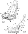
Fig. 1 is perspective view of a first exemplary reclining seat assembly for a vehicle, in accordance with the invention; -
Fig. 2 is a side view of the first seat assembly ofFig. 1 ; -
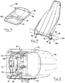
Fig. 3 and 4 are perspective views of the contoured seat pan and contoured backrest frame, respectively, of the first seat assembly ofFig. 1 ; -
Fig. 5 is a bottom view of the first seat assembly ofFig. 1 ; -
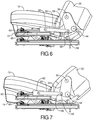
Figs. 6 and 7 are partial side views of the first seat assembly ofFig. 1 , with the seat frame's side member removed to show movement of the seat/seat cushion and backrest relative to each other, to the seat frame, and to a seat frame-mounted seat track; -
Fig. 8 is a partial perspective view of the seat frame, backrest frame, and backrest recline angle adjuster of a second exemplary reclining seat assembly, featuring a pair of manual backrest recline angle adjusters with which to maintain the position of the rear seat pan pivot axis relative to the seat frame, wherein the actuators are pivotally mounted to the seat frame's front cross-member; and -
Fig. 9 is a partial perspective view of the seat frame, backrest frame, and backrest recline angle adjuster of a third exemplary reclining seat assembly, similar to that ofFig. 8 , wherein the manual recline adjuster is replaced with a motor-driven screw drive. - Referring to
Figs. 1-5 , a first exemplary recliningseat assembly 10 for a vehicle includes a bottom seat (hereinafter "seat 12") including aseat pan 14 andseat cushion 16 supported atop aseat frame 18. Theseat frame 18 includesside members 20 whose raisedrear portions 22 include a first pair of transversely-alignedbores 24 with which to define abackrest pivot axis 26 that, in the case of a forward-facing vehicle seat assembly, is generally perpendicular to the nominallongitudinal axis 28 of the vehicle. - A seat back or
backrest 30 including abackrest frame 32 andbackrest cushion 34 is supported on theseat frame 18 for pivoting movement about thebackrest pivot axis 26 by a pair ofcomplementary projections 36 on thebackrest frame 32 that are pivotally received within the seat frame'sside member bores 24. As best seen inFigs. 1 and 2 , thebackrest pivot axis 26 as defined by theside members 20 is located relatively forward of the backrest cushion's central forward-facingsurface 38 when thebackrest 30 is disposed in a generally upright position. In this way, thebackrest pivot axis 26 is advantageously positioned relatively closer to the nominal hip joint of a vehicle passenger seated in theseat assembly 10. Thebackrest frame 32 is preferably also contoured to fit an average front seat passenger, with the outboard edges of the backrest curving forward to thereby open up additional space behind thebackrest 30 for use by a rear seat passenger, which would otherwise be occupied by conventional backrest frames. - As best seen in
Fig. 3-5 , thebackrest frame 32 includes downward extensions 40 (relative to the backrest pivot axis 26) which include a second pair of transversely-alignedbores 42 with which to define a rear seatpan pivot axis 44 that is generally below and parallel to thebackrest pivot axis 26 when thebackrest 30 is disposed in a generally upright position. Therear portion 46 of theseat pan 14 is pivotally supported by thedownward extensions 40 of thebackrest frame 32 upon receipt inbores 42 of a pair of outwardly-extending projections or pins 48 defined on therear portion 46 of theseat pan 14. It will be appreciated that, when the pins 48 are integrally formed on theseat pan 14, for example, by casting, the resulting "contoured"seat pan 14 can advantageously obviate the need for a rigid cross-member that otherwise typically extends across the rear of the seat frame, beneath the rear of the seat cushion, thereby improving available foot room for back seat passengers. Theforward portion 50 of theseat pan 14 is supported on theseat frame 18 for relative longitudinal movement by acoupling 52 including a pair oflinks 54 pivotally mounted on a forwardseat frame cross-member 56 and suitably secured to the underside of theseat pan 14 as byfasteners 58. - By way of further example, in the
first seat assembly 10 as illustrated inFig. 6 , the rear seatpan pivot axis 44 is located perhaps about 100 mm lower than, and perhaps about 30 mm rearward of, thebackrest pivot axis 26 when thebackrest 30 is adjusted to a generally upright position relative to theseat frame 18. In this manner, the offset between theseat cushion 16 and thebackrest cushion 34 advantageously remains substantially unchanged relative to the seated passenger across a range of backrest recline angles, thereby reducing the likelihood of an unsightly gap between theseat cushion 16 and thebackrest cushion 34 at any given backrest recline angle, and to advantageously permit thebackrest 30 to recline flat without creating a vertical step between theseat cushion 16 and thebackrest cushion 34. Theseat cushion 16 also preferably includes multi-density foam to thereby provide suitable cushioning to a seated passenger while obviating the need for a suspension matt and surrounding cushion frame, to provide additional foot room for back row passengers. As can be seen fromFigs. 6 and 7 ,backrest frame 32 reclines relative toseat frame 18 upon forward longitudinal movement of the rearseat pan axis 44 relative to theseat frame 18 and tobackrest pivot axis 26. - Referring again to
Fig. 6 , and also toFig. 7 , thefirst seat assembly 10 features a backrestrecline angle adjuster 60 that includes a pair oflinear actuators 62 comprising a track (63) mounted on theseat frame 18 with a slide (65) that is coupled with alink 64 topins 66 mounted on thedownward extensions 40 on either side of thebackrest frame 32, for pivoting movement about anactuator axis 68 that is offset from and generally parallel to thebackrest pivot axis 26. In thefirst seat assembly 10, theactuator axis 68 is offset from the rear seatpan pivot axis 44 to thereby advantageously provide a slightly longer lever arm on thebackrest frame extension 40 with which to control backrest recline angle using the backrestrecline angle adjuster 60. It will be appreciated that the backrest recline angle adjuster is advantageously located forward and under theseat cushion 16 andseat pan 14, rather than along thepivot axis 26 of thebackrest 30 as is typical of know reclining seat assemblies. - Referring to
Figs. 8 and 9 , a second and third exemplary recliningseat assembly linear actuators seat frame cross-member 70 and directly coupled to a correspondingactuator pivot pin 72 on thebackrest frame 32. In thethird seat assembly 88, thelinear actuator 92 includes ascrew drive 74 that is powered by amotor 76 mounted on theseat frame 18. Further, in each of the second andthird seat assemblies guide rods 78 that are received within the complementary bores ofsliders 80 that are themselves pivotally mounted on a forwardseat frame cross-member 82, to thereby support the seat pan for relative longitudinal movement on theseat frame 18. It will be seen that theactuator pivot pin 72 for thelinear actuators third seat assemblies actuator axis 84 that is collinear with the rear seat pan pivot axis. - From the foregoing, it will be appreciated that a reclining seat assembly in accordance with the invention advantageously improves rear seat passenger foot, knee room, and legroom improvement, while further providing a seated passenger with improved comfort due to a more ergonomic backrest-recline-axis geometry.
While the above description constitutes an exemplary embodiment, it will be appreciated that the invention is susceptible to modification, variation and change. For example, while the invention is disclosed above in connection with the front seat of a passenger vehicle, it will be appreciated that the invention is equally suited for other seating applications, including without limitation aircraft and other vehicle seating, and reclining chairs generally. Further, the invention contemplates providing a pivot release on one of the seat pan and backrest, as through use of a release bracket, to thereby permit forward rotation of the backrest about the upper axis into a folded or "stowed" position. And, while the exemplary reclining seat assemblies described above feature a contoured rear surface on the backrest to enhance knee room/legroom of a rear seat passenger, as best seen inFigs. 1 and3 , it will be appreciated that the invention alternatively contemplates use, for example, of a more conventional, "flatter" rear surface on the backrest, such that the relatively outboard space on the backrest aft of the first pivot may advantageously define integrated storage space, or perhaps even a ventilation duct by which to deliver climate-controlled air to a rear seat passenger. Similarly, while the exemplary embodiment employs a multi-density foam seat cushion supported by the seat pan to obviating the need for a suspension matt and surrounding cushion frame, it will be appreciated that, where desired, the seat pan may otherwise include an additional or alternative suspension mechanism underpinning the seat cushion or seating surface. - Further, it will be appreciated that the relative height of the backrest pivot axis may be adjusted, relative to the overall height of the backrest and the rear seat pan pivot axis, to advantageously achieve a desired correlation between a given longitudinal displacement of the seat pan and a given change in the angle of inclination of the backrest. And, while the rear portion of the seat pan of the disclosed exemplary seat assemblies are directly coupled to the downwardly-extending lower portion of the backrest frame, it will be appreciated that the rear portion of the seat pan may be indirectly coupled to the backrest frame by a pair of seat pan-supporting links which, for example, either rotate in unison with the backrest frame about the backrest pivot axis or are alternatively driven by a suitable cam, gearing, or other arrangement to thereby rotate at a different speed, or in a nonlinear relation, with respect to the backrest frame.
Claims (15)
- A reclining seat assembly (10) comprising:a seat frame (18) defining a longitudinal axis (28) and a backrest pivot axis (26) generally perpendicular to the longitudinal axis (28);a backrest frame (32) supported by the seat frame (18) for movement about the backrest pivot axis (26), wherein the backrest frame (32) defines a rear seat pan pivot axis (44) generally below and parallel to the backrest pivot axis (26) and rearwardly of the backrest pivot axis (26) when the backrest frame (32) is in an upright position;a seat pan (14) having a forward portion (50) and a rearward portion (46), wherein the forward portion (50) of the seat pan (14) is supported by the seat frame (18) for relative longitudinal movement, and the rearward portion (46) of the seat pan (14) is supported by the backrest frame (32) for pivotal movement about the rear seat pan pivot axis (44), whereby the backrest frame (32) reclines relative to the seat frame (18) upon forward longitudinal movement of the rear seat pan pivot axis (44) relative to the seat frame (18); anda backrest recline angle adjuster (60) coupled to the backrest frame (32), the adjuster (60) maintaining the rear seat pan pivot axis (44) in a selected one of a plurality of longitudinal positions relative to the seat frame (18).
- The seat assembly of claim 1, wherein the forward portion (50) of the seat pan (14) is coupled to the seat frame (18) by a coupling (52) mounted on the seat frame (18).
- The seat assembly of claim 2, wherein the coupling (52) is pivotally mounted on a forward portion (56) of the seat frame (18).
- The seat assembly of claim 2, wherein the coupling (52) includes a guide rod (78) and slider (80).
- The seat assembly of claim 4, wherein the guide rod (78) extends generally longitudinally on the seat pan (14), and the slider (80) is pivotally mounted on a forward portion (82) of the seat frame (18).
- The seat assembly of claim 2, wherein the coupling (52) includes a pair of parallel links (54) pivotally mounted on a forward portion (56) of the seat frame (18).
- The seat assembly of claim 1, wherein the backrest frame (32) defines an actuator pivot axis (68) generally below and parallel to the backrest pivot axis (26); and wherein the adjuster (60) includes a linear actuator (62) carried on the seat frame (18), the actuator (62) being pivotally coupled to the backrest frame (32) along the actuator pivot axis (68).
- The seat assembly of claim 7, wherein the actuator pivot axis (68) is collinear with the rear seat pan pivot axis (44).
- The seat assembly of claim 7, wherein the actuator (62) includes a track (63) extending generally longitudinally on the seat frame, a slide(65) movable on the track (63), and a link (64) pivotally coupling the slide to the actuator pivot axis (62).
- The seat assembly of claim 7, wherein the actuator (62) includes a screw drive (74) coupling the seat frame (18) to the actuator pivot axis (68).
- The seat assembly of claim 1, wherein the seat frame includes a spaced pair of side members (20), and wherein the backrest pivot axis (26) is defined by a first cylindrical projection (36) on one of each side member (20) and each side of the backrest frame (32), and a first bore (24) complementary to the first cylindrical projection (36) on the other of each side member (20) and each side of the backrest frame (32).
- The seat assembly of claim 1, wherein the rear seat pan pivot axis (44) is defined by a second cylindrical projection (48) on one of each side of the seat pan (14) and each side of the backrest frame (32), and a second bore (42) complementary to the second cylindrical projection (48) on the other of each side of the seat pan (14) and each side of the backrest frame (32).
- The seat assembly of claim 1, including a backrest cushion (34) supported by the backrest frame (32), and wherein a central portion of a forward-facing surface (38) of the backrest cushion (34) is disposed rearward of the backrest pivot axis (26) when the backrest frame (32) is in an upright position relative to the seat frame (18).
- The seat assembly of claim 12 wherein a second cylindrical projection (48) on each side of the seat pan (14) and each side of the backrest frame (32) is integrally formed on the seat pan (14) with resulting contoured seat pan obviating the need for a rigid cross-member extending across a rear of the seat frame (18) beneath a rear of a seat cushion (16) supported atop the seat frame (18).
- The seat assembly of claim 1 whereby the backrest frame (32) reclines relative to the seat frame (18) upon forward longitudinal movement of the rear seat pan pivot axis (44) relative to the seat frame (18) and to the backrest pivot axis (26).
Applications Claiming Priority (2)
| Application Number | Priority Date | Filing Date | Title |
|---|---|---|---|
| US13/347,815 US20130175841A1 (en) | 2012-01-11 | 2012-01-11 | Reclining seat assembly |
| PCT/US2013/021117 WO2013106630A1 (en) | 2012-01-11 | 2013-01-11 | Reclining seat assembly |
Publications (2)
| Publication Number | Publication Date |
|---|---|
| EP2802480A1 EP2802480A1 (en) | 2014-11-19 |
| EP2802480B1 true EP2802480B1 (en) | 2019-12-18 |
Family
ID=47631721
Family Applications (1)
| Application Number | Title | Priority Date | Filing Date |
|---|---|---|---|
| EP13702285.1A Active EP2802480B1 (en) | 2012-01-11 | 2013-01-11 | Reclining seat assembly |
Country Status (5)
| Country | Link |
|---|---|
| US (2) | US20130175841A1 (en) |
| EP (1) | EP2802480B1 (en) |
| CN (1) | CN104080646B (en) |
| BR (1) | BR112014016209A8 (en) |
| WO (1) | WO2013106630A1 (en) |
Families Citing this family (10)
| Publication number | Priority date | Publication date | Assignee | Title |
|---|---|---|---|---|
| CA3123791C (en) | 2013-03-15 | 2023-05-02 | Stryker Corporation | Medical support apparatus |
| US9889773B2 (en) * | 2016-04-04 | 2018-02-13 | Ford Global Technologies, Llc | Anthropomorphic upper seatback |
| US10688890B2 (en) * | 2017-06-19 | 2020-06-23 | Gulfstream Aerospace Corporation | Seat assembly that reclines and includes a back panel |
| US10343558B2 (en) | 2017-10-19 | 2019-07-09 | Nio Usa, Inc. | Fixed structure seat |
| JP7075742B2 (en) * | 2017-11-13 | 2022-05-26 | 日産自動車株式会社 | How to adjust vehicle seats and vehicle seat equipment |
| US10729246B2 (en) | 2017-12-21 | 2020-08-04 | Stryker Corporation | Person support apparatus with shear-reducing pivot assembly |
| US11040775B2 (en) * | 2019-02-04 | 2021-06-22 | Dynamic Safety LLC | Seat assemblies, such as for use in aircraft, and associated systems and methods |
| KR102586461B1 (en) | 2019-03-25 | 2023-10-10 | 현대자동차주식회사 | Fold and dive seat for vehicle |
| US10857917B1 (en) * | 2019-08-20 | 2020-12-08 | Ellen Edwards | Reclining child car seat with adjustable head support |
| USD1002211S1 (en) * | 2021-11-05 | 2023-10-24 | Ussc Acquisition Corp. | Vehicle seat |
Family Cites Families (38)
| Publication number | Priority date | Publication date | Assignee | Title |
|---|---|---|---|---|
| US1149421A (en) | 1913-02-24 | 1915-08-10 | John F Wilmot | Chair. |
| US1166198A (en) * | 1914-04-30 | 1915-12-28 | George Fischrupp | Reclining-chair. |
| US2016119A (en) | 1930-07-11 | 1935-10-01 | Heywood Wakefield Co | Car seat mechanism |
| US2532025A (en) | 1945-02-03 | 1950-11-28 | Dorothy K S Johnson | Resiliently mounted reclining chair |
| US2596760A (en) | 1947-06-27 | 1952-05-13 | Samuel D Bryant | Mechanism to level and erect seat backs |
| GB788410A (en) | 1955-07-25 | 1958-01-02 | Res Interests Ltd | Improvements in or relating to reclining chairs |
| US2823731A (en) * | 1956-02-13 | 1958-02-18 | Herbert W Miller | Article of furniture |
| US3046055A (en) | 1960-02-19 | 1962-07-24 | Anderson Co | Position-adjusting mechanism |
| US3758151A (en) | 1972-02-01 | 1973-09-11 | Dual Manuf And Eng Inc | Reclining chair |
| AT367992B (en) * | 1981-03-17 | 1982-08-25 | Zuend & Co Ag K | SEAT FURNITURE |
| DE3278560D1 (en) * | 1982-07-17 | 1988-07-07 | Itt | Vehicle seat track apparatus |
| DE3429186A1 (en) * | 1984-08-08 | 1986-02-20 | Uredat-Neuhoff, Angela, 4592 Lindern | SEAT, IN PARTICULAR OFFICE CHAIR |
| DE3617624A1 (en) * | 1986-05-26 | 1987-12-03 | Drabert Soehne | CHAIR |
| IT206947Z2 (en) | 1986-06-12 | 1987-10-26 | Pro Cord Srl | CHAIR WITH ARTICULATED BACKREST |
| JPH0520199Y2 (en) * | 1988-11-30 | 1993-05-26 | ||
| DE3916474A1 (en) * | 1989-05-20 | 1990-11-22 | Roeder Soehne Sitzmoebelfab | CHAIR, ESPECIALLY WORK OR OFFICE CHAIR |
| DE3930983C2 (en) | 1989-09-16 | 1993-09-30 | Rolf Voelkle | Seating with an adjustable seat |
| DK0517692T3 (en) * | 1990-02-28 | 1996-02-19 | Svein Asbjoernsen Produktdesig | Adjustable chair |
| JP2910179B2 (en) | 1990-07-26 | 1999-06-23 | アイシン精機株式会社 | Vertical adjustment device for vehicle seat |
| US5360256A (en) | 1993-04-26 | 1994-11-01 | General Motors Corporation | Recliner seat |
| US6010195A (en) * | 1995-11-27 | 2000-01-04 | Lear Corporation | Automotive modular seat frame assembly |
| US5660440A (en) | 1996-02-28 | 1997-08-26 | Fisher Dynamics Corporation | Linear recliner with easy entry memory feature |
| US5634534A (en) | 1996-04-09 | 1997-06-03 | Tachi-S Co., Ltd. | Longitudinal locking mechanism for vehicle seat |
| DE19702328A1 (en) * | 1997-01-23 | 1998-07-30 | Comforto Gmbh | Chair with synchronous mechanism |
| US5918939A (en) | 1997-03-27 | 1999-07-06 | Fisher Dynamics Corporation | Seat recliner with memory dump mechanism |
| GB9706650D0 (en) * | 1997-04-02 | 1997-05-21 | Virgin Atlantic Airways Ltd | A seat |
| US5871259A (en) | 1997-05-12 | 1999-02-16 | Gehart; John | Linear seat-back recliner mechanism |
| WO2001070074A1 (en) * | 2000-03-24 | 2001-09-27 | Giroflex-Entwicklungs-Ag | Seat and backrest assembly for seating, in particular office chairs |
| DE60123477T2 (en) | 2000-12-20 | 2007-06-21 | Intier Automotive Inc., Aurora | SEAT WITH PUBLISHABLE BACKREST ADJUSTMENT AXLE |
| DE10122945A1 (en) * | 2001-05-11 | 2002-12-12 | Armin Sander | Chair, especially office chair |
| US6644743B1 (en) * | 2003-03-04 | 2003-11-11 | Chang-Chen Lin | Chair chassis |
| JP2006123715A (en) * | 2004-10-28 | 2006-05-18 | Nhk Spring Co Ltd | Seat for vehicle |
| JP4883441B2 (en) | 2006-05-19 | 2012-02-22 | テイ・エス テック株式会社 | Automotive seat height adjustment device |
| WO2008120415A1 (en) * | 2007-03-29 | 2008-10-09 | Toyota Boshoku Kabushiki Kaisha | Seat for vehicle |
| JP5396978B2 (en) * | 2009-04-10 | 2014-01-22 | トヨタ紡織株式会社 | Vehicle seat |
| DE102010023055B4 (en) * | 2010-06-08 | 2014-11-20 | Audi Ag | vehicle seat |
| WO2011155557A1 (en) * | 2010-06-11 | 2011-12-15 | 株式会社岡村製作所 | Chair |
| JP5707817B2 (en) * | 2010-09-28 | 2015-04-30 | アイシン精機株式会社 | Vehicle seat reclining device |
-
2012
- 2012-01-11 US US13/347,815 patent/US20130175841A1/en not_active Abandoned
-
2013
- 2013-01-11 CN CN201380005263.5A patent/CN104080646B/en not_active Expired - Fee Related
- 2013-01-11 WO PCT/US2013/021117 patent/WO2013106630A1/en active Application Filing
- 2013-01-11 BR BR112014016209A patent/BR112014016209A8/en not_active Application Discontinuation
- 2013-01-11 EP EP13702285.1A patent/EP2802480B1/en active Active
-
2016
- 2016-02-09 US US15/019,523 patent/US9809133B2/en active Active
Non-Patent Citations (1)
| Title |
|---|
| None * |
Also Published As
| Publication number | Publication date |
|---|---|
| US9809133B2 (en) | 2017-11-07 |
| US20130175841A1 (en) | 2013-07-11 |
| BR112014016209A2 (en) | 2017-06-13 |
| US20160152162A1 (en) | 2016-06-02 |
| WO2013106630A1 (en) | 2013-07-18 |
| CN104080646B (en) | 2016-08-24 |
| BR112014016209A8 (en) | 2017-07-04 |
| CN104080646A (en) | 2014-10-01 |
| EP2802480A1 (en) | 2014-11-19 |
Similar Documents
| Publication | Publication Date | Title |
|---|---|---|
| US9809133B2 (en) | Reclining seat assembly | |
| US9187012B2 (en) | Pivoting and reclining vehicle seating assembly | |
| US10239419B2 (en) | Anthropomorphic pivotable upper seatback support | |
| US5560681A (en) | Seat bottom extension mechanism for passenger seats | |
| CA2935290C (en) | Aircraft seat | |
| US9315130B2 (en) | Articulating head restraint | |
| JP2016520470A (en) | Vehicle seat having simultaneous connection of seat pan and seat back | |
| US9067512B2 (en) | Adjustable seat | |
| JP2013545659A (en) | Aircraft seat | |
| EP3071445B1 (en) | Deployable leg rest assembly | |
| US20090295209A1 (en) | Seat With Pivoting Backrest | |
| CN111572780A (en) | Multi-position adjustable headrest assembly | |
| US6808234B2 (en) | Seat | |
| US10933787B2 (en) | Head restraint follower | |
| US9315120B2 (en) | Comfort recline seat for a vehicle | |
| US9402480B2 (en) | Adjustable seat assembly | |
| JP2021046006A (en) | Armrest device of seat for seating | |
| CN218141180U (en) | Servo armrest framework of seat | |
| US11820257B2 (en) | Vehicle seat arrangement | |
| CN218702863U (en) | Foldable and Shu Tang improved seat frame and seat | |
| JP7352435B2 (en) | Railway vehicle seats |
Legal Events
| Date | Code | Title | Description |
|---|---|---|---|
| PUAI | Public reference made under article 153(3) epc to a published international application that has entered the european phase |
Free format text: ORIGINAL CODE: 0009012 |
|
| 17P | Request for examination filed |
Effective date: 20140811 |
|
| AK | Designated contracting states |
Kind code of ref document: A1 Designated state(s): AL AT BE BG CH CY CZ DE DK EE ES FI FR GB GR HR HU IE IS IT LI LT LU LV MC MK MT NL NO PL PT RO RS SE SI SK SM TR |
|
| DAX | Request for extension of the european patent (deleted) | ||
| REG | Reference to a national code |
Ref country code: DE Ref legal event code: R079 Ref document number: 602013064061 Country of ref document: DE Free format text: PREVIOUS MAIN CLASS: B60N0002060000 Ipc: B60N0002680000 |
|
| GRAP | Despatch of communication of intention to grant a patent |
Free format text: ORIGINAL CODE: EPIDOSNIGR1 |
|
| STAA | Information on the status of an ep patent application or granted ep patent |
Free format text: STATUS: GRANT OF PATENT IS INTENDED |
|
| RIC1 | Information provided on ipc code assigned before grant |
Ipc: B60N 2/22 20060101ALI20190624BHEP Ipc: B60N 2/07 20060101ALI20190624BHEP Ipc: B60N 2/23 20060101ALI20190624BHEP Ipc: B60N 2/12 20060101ALI20190624BHEP Ipc: B60N 2/68 20060101AFI20190624BHEP |
|
| INTG | Intention to grant announced |
Effective date: 20190731 |
|
| GRAS | Grant fee paid |
Free format text: ORIGINAL CODE: EPIDOSNIGR3 |
|
| RAP1 | Party data changed (applicant data changed or rights of an application transferred) |
Owner name: FCA US LLC |
|
| GRAA | (expected) grant |
Free format text: ORIGINAL CODE: 0009210 |
|
| STAA | Information on the status of an ep patent application or granted ep patent |
Free format text: STATUS: THE PATENT HAS BEEN GRANTED |
|
| AK | Designated contracting states |
Kind code of ref document: B1 Designated state(s): AL AT BE BG CH CY CZ DE DK EE ES FI FR GB GR HR HU IE IS IT LI LT LU LV MC MK MT NL NO PL PT RO RS SE SI SK SM TR |
|
| REG | Reference to a national code |
Ref country code: CH Ref legal event code: EP |
|
| REG | Reference to a national code |
Ref country code: IE Ref legal event code: FG4D |
|
| REG | Reference to a national code |
Ref country code: DE Ref legal event code: R096 Ref document number: 602013064061 Country of ref document: DE |
|
| REG | Reference to a national code |
Ref country code: AT Ref legal event code: REF Ref document number: 1214224 Country of ref document: AT Kind code of ref document: T Effective date: 20200115 |
|
| REG | Reference to a national code |
Ref country code: DE Ref legal event code: R082 Ref document number: 602013064061 Country of ref document: DE Representative=s name: CABINET HIRSCH & ASSOCIES, FR |
|
| REG | Reference to a national code |
Ref country code: NL Ref legal event code: MP Effective date: 20191218 |
|
| PG25 | Lapsed in a contracting state [announced via postgrant information from national office to epo] |
Ref country code: GR Free format text: LAPSE BECAUSE OF FAILURE TO SUBMIT A TRANSLATION OF THE DESCRIPTION OR TO PAY THE FEE WITHIN THE PRESCRIBED TIME-LIMIT Effective date: 20200319 Ref country code: LT Free format text: LAPSE BECAUSE OF FAILURE TO SUBMIT A TRANSLATION OF THE DESCRIPTION OR TO PAY THE FEE WITHIN THE PRESCRIBED TIME-LIMIT Effective date: 20191218 Ref country code: FI Free format text: LAPSE BECAUSE OF FAILURE TO SUBMIT A TRANSLATION OF THE DESCRIPTION OR TO PAY THE FEE WITHIN THE PRESCRIBED TIME-LIMIT Effective date: 20191218 Ref country code: BG Free format text: LAPSE BECAUSE OF FAILURE TO SUBMIT A TRANSLATION OF THE DESCRIPTION OR TO PAY THE FEE WITHIN THE PRESCRIBED TIME-LIMIT Effective date: 20200318 Ref country code: SE Free format text: LAPSE BECAUSE OF FAILURE TO SUBMIT A TRANSLATION OF THE DESCRIPTION OR TO PAY THE FEE WITHIN THE PRESCRIBED TIME-LIMIT Effective date: 20191218 Ref country code: LV Free format text: LAPSE BECAUSE OF FAILURE TO SUBMIT A TRANSLATION OF THE DESCRIPTION OR TO PAY THE FEE WITHIN THE PRESCRIBED TIME-LIMIT Effective date: 20191218 Ref country code: NO Free format text: LAPSE BECAUSE OF FAILURE TO SUBMIT A TRANSLATION OF THE DESCRIPTION OR TO PAY THE FEE WITHIN THE PRESCRIBED TIME-LIMIT Effective date: 20200318 |
|
| REG | Reference to a national code |
Ref country code: LT Ref legal event code: MG4D |
|
| PG25 | Lapsed in a contracting state [announced via postgrant information from national office to epo] |
Ref country code: HR Free format text: LAPSE BECAUSE OF FAILURE TO SUBMIT A TRANSLATION OF THE DESCRIPTION OR TO PAY THE FEE WITHIN THE PRESCRIBED TIME-LIMIT Effective date: 20191218 Ref country code: RS Free format text: LAPSE BECAUSE OF FAILURE TO SUBMIT A TRANSLATION OF THE DESCRIPTION OR TO PAY THE FEE WITHIN THE PRESCRIBED TIME-LIMIT Effective date: 20191218 |
|
| PG25 | Lapsed in a contracting state [announced via postgrant information from national office to epo] |
Ref country code: AL Free format text: LAPSE BECAUSE OF FAILURE TO SUBMIT A TRANSLATION OF THE DESCRIPTION OR TO PAY THE FEE WITHIN THE PRESCRIBED TIME-LIMIT Effective date: 20191218 |
|
| PG25 | Lapsed in a contracting state [announced via postgrant information from national office to epo] |
Ref country code: CZ Free format text: LAPSE BECAUSE OF FAILURE TO SUBMIT A TRANSLATION OF THE DESCRIPTION OR TO PAY THE FEE WITHIN THE PRESCRIBED TIME-LIMIT Effective date: 20191218 Ref country code: RO Free format text: LAPSE BECAUSE OF FAILURE TO SUBMIT A TRANSLATION OF THE DESCRIPTION OR TO PAY THE FEE WITHIN THE PRESCRIBED TIME-LIMIT Effective date: 20191218 Ref country code: PT Free format text: LAPSE BECAUSE OF FAILURE TO SUBMIT A TRANSLATION OF THE DESCRIPTION OR TO PAY THE FEE WITHIN THE PRESCRIBED TIME-LIMIT Effective date: 20200513 Ref country code: EE Free format text: LAPSE BECAUSE OF FAILURE TO SUBMIT A TRANSLATION OF THE DESCRIPTION OR TO PAY THE FEE WITHIN THE PRESCRIBED TIME-LIMIT Effective date: 20191218 Ref country code: NL Free format text: LAPSE BECAUSE OF FAILURE TO SUBMIT A TRANSLATION OF THE DESCRIPTION OR TO PAY THE FEE WITHIN THE PRESCRIBED TIME-LIMIT Effective date: 20191218 |
|
| PG25 | Lapsed in a contracting state [announced via postgrant information from national office to epo] |
Ref country code: SK Free format text: LAPSE BECAUSE OF FAILURE TO SUBMIT A TRANSLATION OF THE DESCRIPTION OR TO PAY THE FEE WITHIN THE PRESCRIBED TIME-LIMIT Effective date: 20191218 Ref country code: IS Free format text: LAPSE BECAUSE OF FAILURE TO SUBMIT A TRANSLATION OF THE DESCRIPTION OR TO PAY THE FEE WITHIN THE PRESCRIBED TIME-LIMIT Effective date: 20200418 Ref country code: SM Free format text: LAPSE BECAUSE OF FAILURE TO SUBMIT A TRANSLATION OF THE DESCRIPTION OR TO PAY THE FEE WITHIN THE PRESCRIBED TIME-LIMIT Effective date: 20191218 |
|
| REG | Reference to a national code |
Ref country code: CH Ref legal event code: PL |
|
| REG | Reference to a national code |
Ref country code: DE Ref legal event code: R097 Ref document number: 602013064061 Country of ref document: DE |
|
| PG25 | Lapsed in a contracting state [announced via postgrant information from national office to epo] |
Ref country code: MC Free format text: LAPSE BECAUSE OF FAILURE TO SUBMIT A TRANSLATION OF THE DESCRIPTION OR TO PAY THE FEE WITHIN THE PRESCRIBED TIME-LIMIT Effective date: 20191218 |
|
| REG | Reference to a national code |
Ref country code: AT Ref legal event code: MK05 Ref document number: 1214224 Country of ref document: AT Kind code of ref document: T Effective date: 20191218 Ref country code: BE Ref legal event code: MM Effective date: 20200131 |
|
| PLBE | No opposition filed within time limit |
Free format text: ORIGINAL CODE: 0009261 |
|
| STAA | Information on the status of an ep patent application or granted ep patent |
Free format text: STATUS: NO OPPOSITION FILED WITHIN TIME LIMIT |
|
| PG25 | Lapsed in a contracting state [announced via postgrant information from national office to epo] |
Ref country code: DK Free format text: LAPSE BECAUSE OF FAILURE TO SUBMIT A TRANSLATION OF THE DESCRIPTION OR TO PAY THE FEE WITHIN THE PRESCRIBED TIME-LIMIT Effective date: 20191218 Ref country code: ES Free format text: LAPSE BECAUSE OF FAILURE TO SUBMIT A TRANSLATION OF THE DESCRIPTION OR TO PAY THE FEE WITHIN THE PRESCRIBED TIME-LIMIT Effective date: 20191218 Ref country code: LU Free format text: LAPSE BECAUSE OF NON-PAYMENT OF DUE FEES Effective date: 20200111 |
|
| 26N | No opposition filed |
Effective date: 20200921 |
|
| PG25 | Lapsed in a contracting state [announced via postgrant information from national office to epo] |
Ref country code: LI Free format text: LAPSE BECAUSE OF NON-PAYMENT OF DUE FEES Effective date: 20200131 Ref country code: AT Free format text: LAPSE BECAUSE OF FAILURE TO SUBMIT A TRANSLATION OF THE DESCRIPTION OR TO PAY THE FEE WITHIN THE PRESCRIBED TIME-LIMIT Effective date: 20191218 Ref country code: SI Free format text: LAPSE BECAUSE OF FAILURE TO SUBMIT A TRANSLATION OF THE DESCRIPTION OR TO PAY THE FEE WITHIN THE PRESCRIBED TIME-LIMIT Effective date: 20191218 Ref country code: BE Free format text: LAPSE BECAUSE OF NON-PAYMENT OF DUE FEES Effective date: 20200131 Ref country code: CH Free format text: LAPSE BECAUSE OF NON-PAYMENT OF DUE FEES Effective date: 20200131 |
|
| PG25 | Lapsed in a contracting state [announced via postgrant information from national office to epo] |
Ref country code: IE Free format text: LAPSE BECAUSE OF NON-PAYMENT OF DUE FEES Effective date: 20200111 |
|
| PG25 | Lapsed in a contracting state [announced via postgrant information from national office to epo] |
Ref country code: PL Free format text: LAPSE BECAUSE OF FAILURE TO SUBMIT A TRANSLATION OF THE DESCRIPTION OR TO PAY THE FEE WITHIN THE PRESCRIBED TIME-LIMIT Effective date: 20191218 |
|
| PGFP | Annual fee paid to national office [announced via postgrant information from national office to epo] |
Ref country code: FR Payment date: 20210125 Year of fee payment: 9 Ref country code: IT Payment date: 20210122 Year of fee payment: 9 |
|
| PGFP | Annual fee paid to national office [announced via postgrant information from national office to epo] |
Ref country code: DE Payment date: 20210127 Year of fee payment: 9 Ref country code: GB Payment date: 20210128 Year of fee payment: 9 |
|
| PG25 | Lapsed in a contracting state [announced via postgrant information from national office to epo] |
Ref country code: TR Free format text: LAPSE BECAUSE OF FAILURE TO SUBMIT A TRANSLATION OF THE DESCRIPTION OR TO PAY THE FEE WITHIN THE PRESCRIBED TIME-LIMIT Effective date: 20191218 Ref country code: MT Free format text: LAPSE BECAUSE OF FAILURE TO SUBMIT A TRANSLATION OF THE DESCRIPTION OR TO PAY THE FEE WITHIN THE PRESCRIBED TIME-LIMIT Effective date: 20191218 Ref country code: CY Free format text: LAPSE BECAUSE OF FAILURE TO SUBMIT A TRANSLATION OF THE DESCRIPTION OR TO PAY THE FEE WITHIN THE PRESCRIBED TIME-LIMIT Effective date: 20191218 |
|
| PG25 | Lapsed in a contracting state [announced via postgrant information from national office to epo] |
Ref country code: MK Free format text: LAPSE BECAUSE OF FAILURE TO SUBMIT A TRANSLATION OF THE DESCRIPTION OR TO PAY THE FEE WITHIN THE PRESCRIBED TIME-LIMIT Effective date: 20191218 |
|
| REG | Reference to a national code |
Ref country code: DE Ref legal event code: R119 Ref document number: 602013064061 Country of ref document: DE |
|
| GBPC | Gb: european patent ceased through non-payment of renewal fee |
Effective date: 20220111 |
|
| PG25 | Lapsed in a contracting state [announced via postgrant information from national office to epo] |
Ref country code: GB Free format text: LAPSE BECAUSE OF NON-PAYMENT OF DUE FEES Effective date: 20220111 Ref country code: DE Free format text: LAPSE BECAUSE OF NON-PAYMENT OF DUE FEES Effective date: 20220802 |
|
| PG25 | Lapsed in a contracting state [announced via postgrant information from national office to epo] |
Ref country code: FR Free format text: LAPSE BECAUSE OF NON-PAYMENT OF DUE FEES Effective date: 20220131 |
|
| PG25 | Lapsed in a contracting state [announced via postgrant information from national office to epo] |
Ref country code: IT Free format text: LAPSE BECAUSE OF NON-PAYMENT OF DUE FEES Effective date: 20220111 |